

Page 1

Z9PH-D16 Series
Z9PH-D16
Z9PH-D16/QDR
Z9PH-D16/FDR
Motherboard
Page 2

E7171
Revised Edition V2
March 2012
Copyright © 2012 ASUSTeK COMPUTER INC. All Rights Reserved.
No part of this manual, including the products and software described in it, may be reproduced, transmitted,
transcribed, stored in a retrieval system, or translated into any language in any form or by any means,
except documentation kept by the purchaser for backup purposes, without the express written permission
of ASUSTeK COMPUTER INC. (“ASUS”).
Product warranty or service will not be extended if: (1) the product is repaired, modied or altered, unless
such repair, modication of alteration is authorized in writing by ASUS; or (2) the serial number of the
product is defaced or missing.
ASUS PROVIDES THIS MANUAL “AS IS” WITHOUT WARRANTY OF ANY KIND, EITHER EXPRESS
OR IMPLIED, INCLUDING BUT NOT LIMITED TO THE IMPLIED WARRANTIES OR CONDITIONS OF
MERCHANTABILITY OR FITNESS FOR A PARTICULAR PURPOSE. IN NO EVENT SHALL ASUS, ITS
DIRECTORS, OFFICERS, EMPLOYEES OR AGENTS BE LIABLE FOR ANY INDIRECT, SPECIAL,
INCIDENTAL, OR CONSEQUENTIAL DAMAGES (INCLUDING DAMAGES FOR LOSS OF PROFITS,
LOSS OF BUSINESS, LOSS OF USE OR DATA, INTERRUPTION OF BUSINESS AND THE LIKE),
EVEN IF ASUS HAS BEEN ADVISED OF THE POSSIBILITY OF SUCH DAMAGES ARISING FROM ANY
DEFECT OR ERROR IN THIS MANUAL OR PRODUCT.
SPECIFICATIONS AND INFORMATION CONTAINED IN THIS MANUAL ARE FURNISHED FOR
INFORMATIONAL USE ONLY, AND ARE SUBJECT TO CHANGE AT ANY TIME WITHOUT NOTICE, AND
SHOULD NOT BE CONSTRUED AS A COMMITMENT BY ASUS. ASUS ASSUMES NO RESPONSIBILITY
OR LIABILITY FOR ANY ERRORS OR INACCURACIES THAT MAY APPEAR IN THIS MANUAL,
INCLUDING THE PRODUCTS AND SOFTWARE DESCRIBED IN IT.
Products and corporate names appearing in this manual may or may not be registered trademarks or
copyrights of their respective companies, and are used only for identication or explanation and to the
owners’ benet, without intent to infringe.
ii
Page 3

Contents
Notices ........................................................................................................ vii
Federal Communications Commission Statement ........................... vii
Canadian Department of Communications Statement ..................... vii
REACH ..........................................................................................
Safety information .................................................................................... viii
Electrical safety ............................................................................... viii
Operation safety .............................................................................. viii
About this guide ......................................................................................... ix
How this guide is organized ..............................................................ix
Where to nd more information .........................................................ix
Conventions used in this guide ..........................................................x
Typography ........................................................................................x
Z9PH-D16 Series specications summary ............................................... xi
Z9PH-D16 Series specications summary .............................................. xii
Chapter 1: Product introduction
1.1 Welcome! ...................................................................................... 1-3
1.2 Package contents .........................................................................
1.3 Serial number label ......................................................................
1.4 Special features ............................................................................
1.4.1 Product highlights ...........................................................
1.4.2 Innovative ASUS features ...............................................
vii
1-3
1-4
1-4
1-4
1-6
Chapter 2: Hardware information
2.1 Before you proceed ..................................................................... 2-3
2.2 Motherboard overview .................................................................
2.2.1 Placement direction ........................................................
2.2.2 Screw holes ....................................................................
2.2.3 Motherboard layout .........................................................
2.2.3 Motherboard layout .........................................................
2.2.4 Layout contents ...............................................................
2.3 Central Processing Unit (CPU) ...................................................
2.3.1 Installing the CPU ...........................................................
2.3.2 Installing the CPU heatsink ...........................................
2.4 System memory .........................................................................
2.4.1 Overview .......................................................................
2.4.2 Memory Congurations .................................................
2.5 Expansion slots ..........................................................................
2.5.1 Installing an expansion card .........................................
2-4
2-4
2-4
2-5
2-6
2-7
2-9
2-9
2-14
2-15
2-15
2-16
2-18
2-18
iii
Page 4

Contents
2.5.2 Conguring an expansion card ..................................... 2-18
2.5.3 Interrupt assignments ...................................................
2.5.4 PCI Express x16 slot (x16 link) .....................................
2.5.5 Installing ASMB6 management board ...........................
2.6 Jumpers ......................................................................................
2.7 Connectors .................................................................................
2.7.1 Rear panel connectors ..................................................
2.7.2 Internal connectors .......................................................
2.8 Internal LEDs ..............................................................................
Chapter 3: Powering up
3.1 Starting up for the rst time ........................................................ 3-3
3.2 Powering off the computer ..........................................................
3.2.1 Using the OS shut down function ....................................
3.2.2 Using the dual function power switch ..............................
Chapter 4: BIOS setup
4.1 Managing and updating your BIOS ............................................ 4-3
4.1.1 ASUS CrashFree BIOS 3 utility ......................................
4.1.2 ASUS EZ Flash 2 Utility ..................................................
4.1.3 BUPDATER utility
4.2 BIOS setup program ....................................................................
4.2.1 BIOS menu screen ..........................................................
4.2.2 Menu bar .........................................................................
4.2.3 Menu items .....................................................................
4.2.4 Submenu items ...............................................................
4.2.5 Navigation keys ...............................................................
4.2.6 General help ...................................................................
4.2.7 Conguration elds .........................................................
4.2.8 Pop-up window ...............................................................
4.2.9 Scroll bar .........................................................................
4.3 Main menu ..................................................................................
4.3.1 System Date [Day xx/xx/xxxx] .......................................
4.3.2 System Time [xx:xx:xx] .................................................
4.4 Advanced menu .........................................................................
4.4.1 CPU Conguration .........................................................
4.4.2 CPU Power Management Conguration .......................
4.4.3 Chipset Conguration ...................................................
4.4.4 PCH SATA Conguration ..............................................
............................................................ 4-5
2-19
2-19
2-20
2-21
2-24
2-24
2-26
2-34
3-4
3-4
3-4
4-3
4-4
4-7
4-8
4-8
4-9
4-9
4-9
4-9
4-9
4-9
4-9
4-10
4-10
4-10
4-11
4-11
4-13
4-15
4-20
iv
Page 5

Contents
4.4.5 PCH SCU Conguration ............................................... 4-22
4.4.6 PCI Subsystem Settings ...............................................
4.4.7 Intel TXT(LT-SX) Conguration .....................................
4.4.8 USB Conguration ........................................................
4.4.9 Trusted Computing ........................................................
4.4.10 ACPI Settings ................................................................
4.4.11 WHEA Conguration .....................................................
4.4.12 APM setting ...................................................................
4.4.13 Onboard LAN Conguration ..........................................
4.4.14 Serial Port Console Redirection ....................................
4.4.15 ME Subsystem ..............................................................
4.4.16 Legacy Devices Conguration ......................................
4.4.17 Runtime Error Logging ..................................................
4.5 Server Mgmt menu .....................................................................
4.5.1 System Event Log .........................................................
4.5.2 BMC network conguration ...........................................
4.6 Event Logs menu .......................................................................
4.6.1 Change Smbios Event Log Settings .............................
4.7 Boot menu ..................................................................................
4.8 Monitor menu .............................................................................
4.9 Security menu ............................................................................
4.10 Tool menu ...................................................................................
4.11 Exit menu ....................................................................................
4-22
4-25
4-26
4-27
4-28
4-29
4-29
4-30
4-31
4-34
4-34
4-35
4-36
4-37
4-38
4-39
4-39
4-41
4-43
4-44
4-45
4-46
Chapter 5: RAID conguration
5.1 Setting up RAID ............................................................................ 5-3
5.1.1 RAID denitions ..............................................................
5.1.2 Installing hard disk drives ................................................
5.1.3 Setting the RAID item in BIOS ........................................
5.1.4 RAID conguration utilities ..............................................
5.2 LSI Software RAID Conguration Utility ...................................
5.2.1 Creating a RAID set ........................................................
5.2.2 Adding or viewing a RAID conguration .......................
5.2.3 Initializing the virtual drives ...........................................
5.2.4 Rebuilding failed drives .................................................
5.2.5 Checking the drives for data consistency .....................
5.2.6 Deleting a RAID conguration .......................................
5.2.7 Selecting the boot drive from a RAID set ......................
5-3
5-4
5-4
5-4
5-5
5-6
5-12
5-13
5-17
5-19
5-22
5-23
v
Page 6

Contents
5.2.8 Enabling WriteCache .................................................... 5-24
®
5.3 Intel
Option ROM Utility .....................................................................
5.4 Intel
Chapter 6: Driver installation
6.1 RAID driver installation ............................................................... 6-3
6.2 Intel
6.3 Intel
6.4 VGA driver installation
6.5 Intel
6.6 Intel
6.7 Intel
6.8 Management applications and utilities installation ................
6.9 Mellanox ConnectX-3 Inniband driver installation
(Z9PH-D16/QDR and Z9PH-D16/FDR only) ...............................
Rapid Storage Technology enterprise SCU/SATA
5.3.1 Creating a RAID set ......................................................
5.3.2 Creating a Recovery set ...............................................
5.3.3 Deleting a RAID set ......................................................
5.3.4 Resetting disks to Non-RAID ........................................
5.3.5 Exiting the Intel
®
Rapid Storage Technology utility ........ 5-32
5.3.6 Rebuilding the RAID .....................................................
5.3.7 Setting the Boot array in the BIOS Setup Utility ............
®
Rapid Storage Technology enterprise Utility (Windows) 5-35
5.4.1 Creating a RAID set ......................................................
5.4.2 Change Volume Type ....................................................
5.4.3 Delete volume ...............................................................
5.4.4 Preferences ...................................................................
6.1.1 Creating a RAID driver disk ............................................
6.1.2 Installing the RAID controller driver ................................
®
Chipset Device Software installation ............................. 6-16
@
Network Connections Software installation.................. 6-18
............................................................... 6-21
®
C600 Series Chipset SATA RAID Drivers ....................... 6-24
®
Rapid Storage Technology enterprise 3.0 installation . 6-25
®
PRO/1000 Gigabit Adapters Driver installation ............. 6-28
6.8.1 Running the support DVD .............................................
6.8.2 Drivers menu .................................................................
6.8.3 Utilities menu ................................................................
6.8.4 Make disk menu ............................................................
6.8.5 Contact information .......................................................
6.9.1 Windows operating system ................................................. 6-34
6.9.2 Red Hat® Enterprise Linux OS ............................................. 6-37
5-25
5-27
5-28
5-30
5-31
5-32
5-34
5-36
5-38
5-39
5-40
6-3
6-6
6-32
6-32
6-32
6-33
6-33
6-33
6-34
Appendix: Reference information
A.1 Z9PH-D16 Series block diagram .......................................................A-3
ASUS contact information .......................................................................... 1
vi
Page 7

Notices
Federal Communications Commission Statement
This device complies with Part 15 of the FCC Rules. Operation is subject to the
following two conditions:
• This device may not cause harmful interference, and
• This device must accept any interference received including interference that
may cause undesired operation.
This equipment has been tested and found to comply with the limits for a Class
B digital device, pursuant to Part 15 of the FCC Rules. These limits are designed
to provide reasonable protection against harmful interference in a residential
installation. This equipment generates, uses and can radiate radio frequency energy
and, if not installed and used in accordance with manufacturer’s instructions, may
cause harmful interference to radio communications. However, there is no guarantee
that interference will not occur in a particular installation. If this equipment does
cause harmful interference to radio or television reception, which can be determined
by turning the equipment off and on, the user is encouraged to try to correct the
interference by one or more of the following measures:
• Reorient or relocate the receiving antenna.
• Increase the separation between the equipment and receiver.
• Connect the equipment to an outlet on a circuit different from that to which the
receiver is connected.
• Consult the dealer or an experienced radio/TV technician for help.
The use of shielded cables for connection of the monitor to the graphics card is
required to assure compliance with FCC regulations. Changes or modications
to this unit not expressly approved by the party responsible for compliance could
void the user’s authority to operate this equipment.
Canadian Department of Communications Statement
This digital apparatus does not exceed the Class B limits for radio noise emissions
from digital apparatus set out in the Radio Interference Regulations of the
Canadian Department of Communications.
This class B digital apparatus complies with Canadian ICES-003.
REACH
Complying with the REACH (Registration, Evaluation, Authorization, and Restriction
of Chemicals) regulatory framework, we publish the chemical substances in our
products at ASUS REACH website at http://csr.asus.com/english/REACH.htm.
vii
Page 8

Safety information
Electrical safety
• To prevent electrical shock hazard, disconnect the power cable from the
electrical outlet before relocating the system.
• When adding or removing devices to or from the system, ensure that the
power cables for the devices are unplugged before the signal cables are
connected. If possible, disconnect all power cables from the existing system
before you add a device.
• Before connecting or removing signal cables from the motherboard, ensure
that all power cables are unplugged.
• Seek professional assistance before using an adapter or extension cord.
These devices could interrupt the grounding circuit.
• Make sure that your power supply is set to the correct voltage in your area.
If you are not sure about the voltage of the electrical outlet you are using,
contact your local power company.
• If the power supply is broken, do not try to x it by yourself. Contact a
qualied service technician or your retailer.
Operation safety
• Before installing the motherboard and adding devices on it, carefully read all
the manuals that came with the package.
• Before using the product, make sure all cables are correctly connected and the
power cables are not damaged. If you detect any damage, contact your dealer
immediately.
• To avoid short circuits, keep paper clips, screws, and staples away from
connectors, slots, sockets and circuitry.
• Avoid dust, humidity, and temperature extremes. Do not place the product in
any area where it may become wet.
• Place the product on a stable surface.
• If you encounter technical problems with the product, contact a qualied
service technician or your retailer.
viii
throw the motherboard in municipal waste. This product has been
DO NOT
designed to enable proper reuse of parts and recycling. This symbol of the
crossed out wheeled bin indicates that the product (electrical and electronic
equipment) should not be placed in municipal waste. Check local regulations for
disposal of electronic products.
throw the mercury-containing button cell battery in municipal waste.
DO NOT
This symbol of the crossed out wheeled bin indicates that the battery should not
be placed in municipal waste.
Page 9

About this guide
This user guide contains the information you need when installing and conguring
the motherboard.
How this guide is organized
This user guide contains the following parts:
• Chapter 1: Product introduction
This chapter describes the features of the motherboard and the new
technologies it supports.
• Chapter 2: Hardware information
This chapter lists the hardware setup procedures that you have to perform
when installing system components. It includes description of the switches,
jumpers, and connectors on the motherboard.
• Chapter 3: Powering up
This chapter describes the power up sequence and ways of shutting down
the system.
• Chapter 4: BIOS setup
This chapter tells how to change system settings through the BIOS Setup
menus. Detailed descriptions of the BIOS parameters are also provided.
• Chapter 5: RAID conguration
This chapter provides instructions for setting up, creating, and conguring
RAID sets using the available utilities.
• Chapter 6: Driver installation
This chapter provides instructions for installing the necessary drivers for
different system components.
• Appendix: Reference information
This appendix includes additional information that you may refer to when
conguring the motherboard.
Where to nd more information
Refer to the following sources for additional information and for product and
software updates.
1. ASUS websites
The ASUS website provides updated information on ASUS hardware and
software products. Refer to the ASUS contact information.
2. Optional documentation
Your product package may include optional documentation, such as warranty
yers, that may have been added by your dealer. These documents are not
part of the standard package.
ix
Page 10

Conventions used in this guide
To make sure that you perform certain tasks properly, take note of the following
symbols used throughout this manual.
DANGER/WARNING:
when trying to complete a task.
CAUTION:
when trying to complete a task.
IMPORTANT:
task.
NOTE:
task.
Information to prevent damage to the components
Instructions that you MUST follow to complete a
Tips and additional information to help you complete a
Information to prevent injury to yourself
Typography
Bold text Indicates a menu or an item to select.
Italics Used to emphasize a word or a phrase.
<Key> Keys enclosed in the less-than and greater than sign means that you must press the
enclosed key.
Example: <Enter> means that you must press
the Enter or Return key.
<Key1+Key2+Key3> If you must press two or more keys
simultaneously, the key names are linked with
a plus sign (+).
Example: <Ctrl+Alt+Del>
Command
exactly as shown, then supply the required
item or value enclosed in brackets.
Example: At the DOS prompt, type the
command line:
x
Means that you must type the command
format A:/S
Page 11
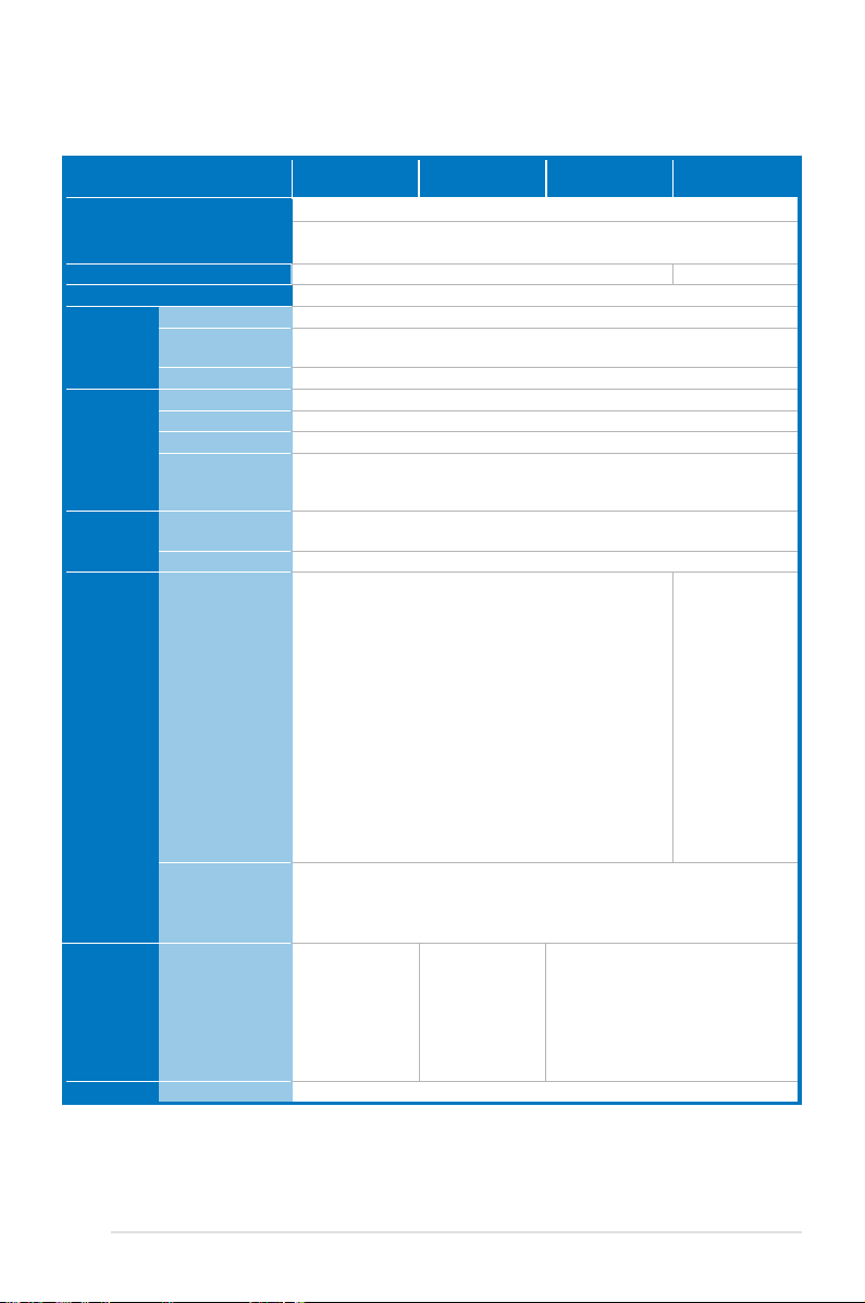
Z9PH-D16 Series specications summary
Model Name Z9PH-D16/FDR Z9PH-D16/QDR Z9PH-D16 Z9PH-D16
Processor Support / System Bus
Core Logic
Form Factor
ASUS
Features
Memory Total Slots
Expansion
Slots
Storage SATA Controller
Networking LAN
Graphic VGA
Fan Speed Control
Dedicated for
Rack
ASWM Enterprise
Capacity
Memory Type
Memory Size
Total PCI/PCI-X/
PCI-E Slots
Slot Location
SAS Controller
2 x Socket® LGA 2011
Intel® Xeon® processor E5-2600 product family
QPI 6.4/7.2/8.0 GT/s
Intel® C602-A Intel® C602-J
ASUS Proprietary , 6.855” x 16.7”
V
V
V
16 (4 Channels per CPU, 8DIMM per CPU)
Maximum up to 512GB
DDR3 800/1066/1333/1600 RDIMM/ECC UDIMM/Non-ECC UDIMM/LR DIMM
1GB, 2GB, 4GB, 8GB, 16GB* (RDIMM)
1GB, 2GB, 4GB, 8GB* (UDIMM)
8GB, 16GB, 32GB* (LRDIMM)
1
1 x PCI-E x16 (X16 Gen3 link)
Intel® C602-A:
<AHCI>
- 2 x SATA 3Gb/s ports, 2 x SATA 6Gb/s ports
®
RSTe (for Windows only)
- Intel
(Support software RAID 0, 1, 10 & 5)
- LSI MegaRAID (for Linux / Windows)
(Support software RAID 0, 1 & 10)
<SCU>
- 4 x SATA 3Gb/s ports
- Intel® RSTe (for Windows only)
(Supports software RAID 0, 1, 10 & 5 for all SATA ports)
Optional kits(PIKE Riser card is necessary):
ASUS PIKE 2008 8-port SAS 6G RAID card
ASUS PIKE 2008/IMR 8-port SAS 6G RAID card
ASUS PIKE 2108 8-port SAS 6G RAID card
- 2 x Intel® 82574L
+ 1 x Mgmt LAN
- 1 x Single
Port Mellanox
ConnectX-3 FDR
Inniband with
QSFP interface
ASPEED® AST2300 + 16MB VRAM
- 2 x Intel® 82574L
+ 1 x Mgmt LAN
- 1 x Single
Port Mellanox
ConnectX-3 QDR
Inniband with
QSFP interface
- 2 x Intel® 82574L + 1 x Mgmt LAN
(C602-J)
Intel® C602-J:
<AHCI>
- 2 x SATA 3Gb/s
ports, 2 x SATA
6Gb/s ports
®
RSTe (for
- Intel
Windows only)
(Support software
RAID 0, 1, 10 &
5)
- LSI MegaRAID
(for Linux /
Windows)
(Support software
RAID 0, 1 & 10)
(continued on the next page)
xi
Page 12
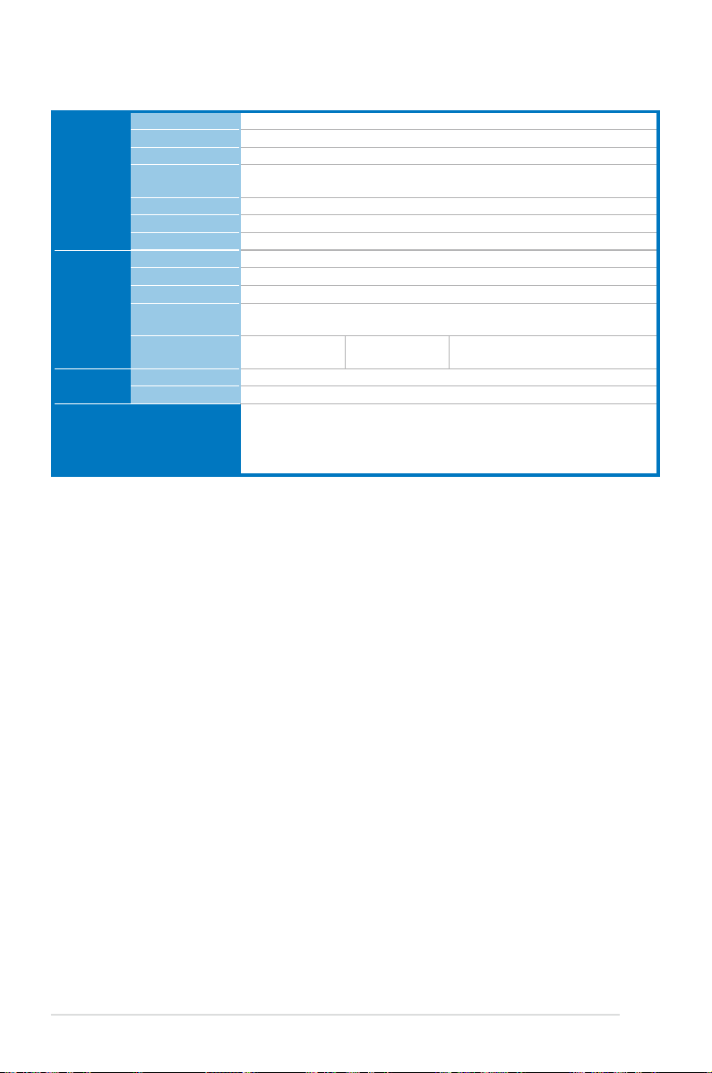
Z9PH-D16 Series specications summary
Onboard I/O
Connectors
Rear I/O
Connectors
Monitoring CPU Temperature
Environment
*Refer to ASUS Server AVL for latest update.
**Specications are subject to change without notice.
TPM Header
PSUSMB Header
PSU Connector
Management
Connector
USB Connectors
Fan Header
Serial Port Header
External USB Port
VGA Port
RJ-45
External Serial
Port
Inniband(QSFP)
Port
FAN RPM
1
1
2 x 20-pin ATX power connector
Onboard socket for management card
2 (1 x Type A USB socket; 1 x USB header)
4 x 4pin
2
1
2 + 1 Management Port
1
1 1 -
V
V
Operating temperature: 10°C – 35°C
Non operating temperature: -40°C – 70°C
Non operating humidity: 20% – 90%
(Non condensing)
xii
Page 13

This chapter describes the motherboard
features and the new technologies it supports.
Product
introduction
1
Page 14

Chapter summary
1
1.1 Welcome! ...................................................................................... 1-3
1.2 Package contents .........................................................................
1.3 Serial number label ......................................................................
1.4 Special features ............................................................................
1-3
1-4
1-4
ASUS Z9PH-D16 Series
Page 15
1.1 Welcome!
Thank you for buying an ASUS® Z9PH-D16 Series motherboard!
The motherboard delivers a host of new features and latest technologies, making it
another standout in the long line of ASUS quality motherboards!
Before you start installing the motherboard, and hardware devices on it, check the
items in your package with the list below.
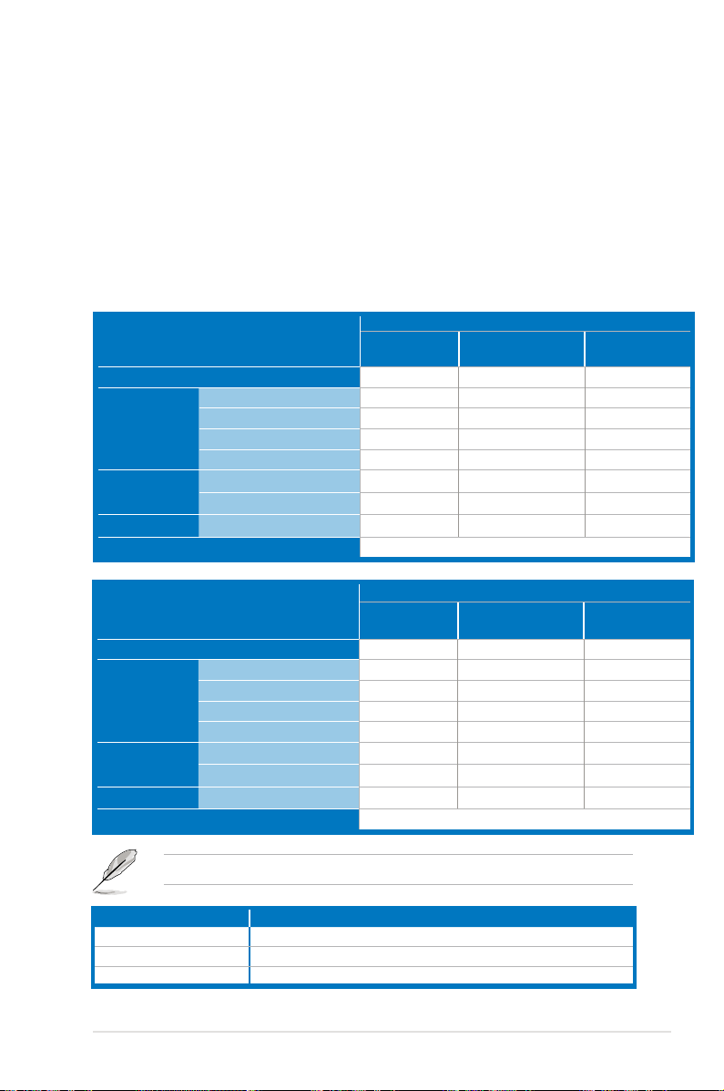
1.2 Package contents
Check your motherboard package for the following items.
ASMB6-iKVM module
Support CD
Application CD
Documentation
Cable Thermistor
Packing Qty.
ASMB6-iKVM module
Application CD
Documentation
Cable Thermistor
Packing Qty.
Mellanox CD
ASWM Enterprise SDVD
ASMB6-iKVM SDVD
Motherboard User Guide
ASMB6-iKVM User Guide
Support CD
Mellanox CD
ASWM Enterprise SDVD
ASMB6-iKVM SDVD
Motherboard User Guide
ASMB6-iKVM User Guide
Standard Bulk Pack
Z9PH-D16 Z9PH-D16(C602-J)
1 1 1
1 1 1
1 1 1
1 1 1
1 1 1
1 1 1
2 2 2
10 pc per carton
Standard Gift Box
Z9PH-D16 Z9PH-D16(C602-J)
1 1 1
1 1 1
1 1 1
1 1 1
1 1 1
1 1 1
2 2 2
1 pc per carton
Z9PH-D16/FDR
Z9PH-D16/QDR
Z9PH-D16/FDR
Z9PH-D16/QDR
1
1
If any of the above items is damaged or missing, contact your retailer.
Optional items Description
PIKE 2108 LSI 8-port SAS2 6G RAID card
PIKE 2008/IMR LSI 8-port SAS2 6G RAID card
PIKE 2008 LSI 8-port SAS2 6G RAID card
ASUS Z9PH-D16 Series 1-3
Page 16

1.3 Serial number label
Before requesting support from the ASUS Technical Support team, you must take
note of the motherboard's serial number containing 12 characters
shown as the gure below. With the correct serial number of the product, ASUS
Technical Support team members can then offer a quicker and satisfying solution
to your problems.
Z9PH-D16/FDR
xxS2xxxxxxxx
Made
in
China
合格
xxS2xxxxxxxx
1.4 Special features
1.4.1 Product highlights
Latest Processor Technology
The motherboard supports the latest Intel Xeon® processor E5-2600 product family
in LGA 2011 package with integrated memory controller to support 4 channel (8
DIMM prt CPU) DDR3 memory. Intel Xeon® processor E5-2600 product family
supports Intel QuickPath Interconnect (QPI) with a system bus of up to 8.0GT/s.
Optimized Intel® Turbo Boost Technology
Optimized Intel® Turbo Boost Technology opportunistically and automatically allows
the processor to run faster than the marked frequency if the processor is operating
below power, temperature and current limits.
Intel® Hyper Threading
The thread-level parallelism on each processor makes more efcient use of the
processor resources, higher processing throughout and improved performance on
today's multi-threaded software.
Intel® EM64T
The motherboard supports Intel® processors with the Intel® EM64T (Extended
Memory 64 Technology). The Intel® EM64T feature allows your computer to run on
64-bit operating systems and access larger amounts of system memory for faster
and more efcient computing.
1-4 Chapter 1: Product introduction
Page 17

DDR3 memory support
The Z9PH-D16 Series supports DDR3 memory that features data transfer rates
of 1600/1333/1066 MHz to meet the higher bandwidth requirements of server
and workstation applications. The 4-channel DDR3 architecture boosts system
performance, eliminating bottlenecks with peak bandwidth of up to 52GB/s. This
voltage reduction limits the power consumption and heat generation of DDR3
which makes it an ideal memory solution. Also, the motherboard can support LRDIMM (Load reduced DIMM) which uses a specially designed buffer to reduce the
data load to a single load and can increase overall server system memory capacity.
PCIe 3.0
The motherboard supports the latest PCIe 3.0 device, which doubles the delivered
bandwidth of PCIe 2.0. This enhances system performance while still providing
backward compatibility to PCIe 2.0.
Intel® 82574L LAN solution
The motherboard comes with dual Gigabit LAN controllers and ports which provide
a total solution for your networking needs. The onboard Intel 82574L Gigabit LAN
controllers use the PCI Express interface and could achieve network throughput
close to Gigabit bandwidth.
Enhanced Intel SpeedStep Technology (EIST)
The Enhanced Intel SpeedStep Technology (EIST) intelligently manages the
CPU resources by automatically adjusting the CPU voltage and core frequency
depending on the CPU loading and system speed or power requirement.
Serial ATA II technology
The motherboard supports the Serial ATA II 3 Gb/s technology through the Serial
ATA interface and Intel® C602 chipset. The Serial ATA II specication provides
twice the bandwidth of the current Serial ATA products with a host of new
features, including Native Command Queuing (NCQ), Power Management (PM)
Implementation Algorithm, and Hot Swap. Serial ATA allows thinner, more exible
cables with lower pin count and reduced voltage requirements.
Serial ATA III technology
The motherboard supports the Serial ATA III technology through the Serial ATA
interface and Intel® C602 chipset, delivering up to 6Gb/s data transfer rates.
Additionally, get enhanced scalability, faster data retrieval, double the bandwidth of
current bus systems.
USB 2.0 technology
The motherboard implements the Universal Serial Bus (USB) 2.0 specication,
dramatically increasing the connection speed from the 12 Mbps bandwidth on USB
1.1 to a fast 480 Mbps on USB 2.0. USB 2.0 is backward compatible with USB 1.1.
ASUS Z9PH-D16 Series 1-5
Page 18

Temperature, fan, and voltage monitoring
The CPU temperature is monitored to prevent overheating and damage. The
system fan rotations per minute (RPM) is monitored for timely failure detection.
The chip monitors the voltage levels to ensure stable supply of current for critical
components.
1.4.2 Innovative ASUS features
ASUS Fan Speed control technology
The ASUS Fan Speed control technology smartly adjusts the fan speeds according
to the system loading to ensure quiet, cool, and efcient operation.
PIKE (Proprietary I/O Kit Expansion)
PIKE is an on-demand upgrade kit for users. This ASUS unique feature enables
users to choose their preferred I/O solutions. ASUS provides multiple SAS
solutions for different segments and purposes and PIKE saves lots of validation
efforts and hardware cost for end users. Moreover, the special patent design offers
multiple I/O solutions without occupying the Slot 6 in 1U system.
1-6 Chapter 1: Product introduction
Page 19

This chapter lists the hardware setup
procedures that you have to perform
when installing system components. It
includes description of the jumpers and
connectors on the motherboard.
Chapter 2:
Hardware
2
information
Page 20

Chapter summary
2
2.1 Before you proceed ..................................................................... 2-3
2.2 Motherboard overview .................................................................
2.3 Central Processing Unit (CPU) ...................................................
2.4 System memory .........................................................................
2.5 Expansion slots ..........................................................................
2.6 Jumpers ......................................................................................
2.7 Connectors .................................................................................
2.8 Internal LEDs ..............................................................................
2-4
2-9
2-15
2-18
2-21
2-24
2-34
ASUS Z9PH-D16 Series
Page 21
2.1 Before you proceed
Take note of the following precautions before you install motherboard components or change
any motherboard settings.
• Unplug the power cord from the wall socket before touching any
component.
• Use a grounded wrist strap or touch a safely grounded object or a metal
object, such as the power supply case, before handling components to
avoid damaging them due to static electricity.
• Hold components by the edges to avoid touching the ICs on them.
• Whenever you uninstall any component, place it on a grounded antistatic
pad or in the bag that came with the component.
• Before you install or remove any component, ensure that the power supply
is switched off or the power cord is detached from the power supply. Failure
to do so may cause severe damage to the motherboard, peripherals, and/or
components.
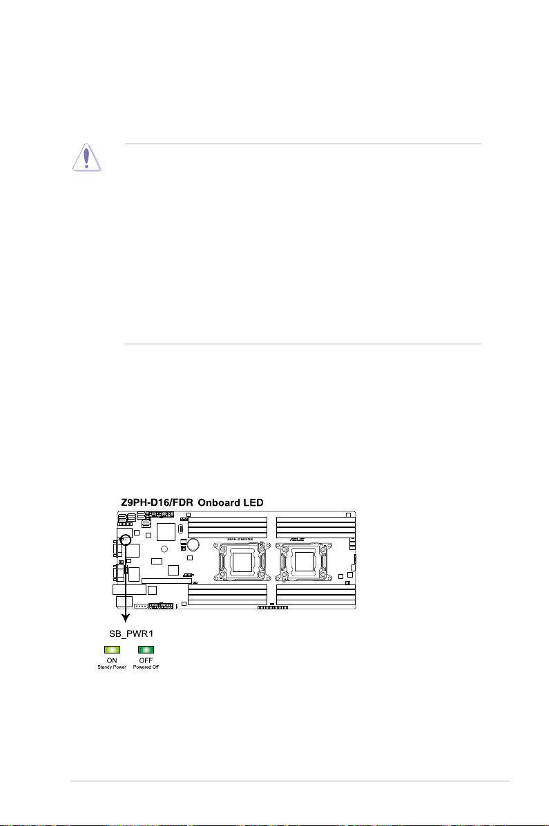
Standby Power LED (SB_PWR1)
The motherboard comes with a standby power LED. The green LED lights up
to indicate that the system is ON, in sleep mode, or in soft-off mode. This is a
reminder that you should shut down the system and unplug the power cable before
removing or plugging in any motherboard component. The illustration below shows
the location of the onboard LED.
ASUS Z9PH-D16 Series 2-3
Page 22
2.2 Motherboard overview
Before you install the motherboard, study the conguration of your chassis to
ensure that the motherboard ts into it.
Ensure to unplug the chassis power cord before installing or removing the
motherboard. Failure to do so can cause you physical injury and damage
motherboard components!
2.2.1 Placement direction
When installing the motherboard, ensure that you place it into the chassis in the
correct orientation. The edge with external ports goes to the rear part of the chassis
as indicated in the image below.
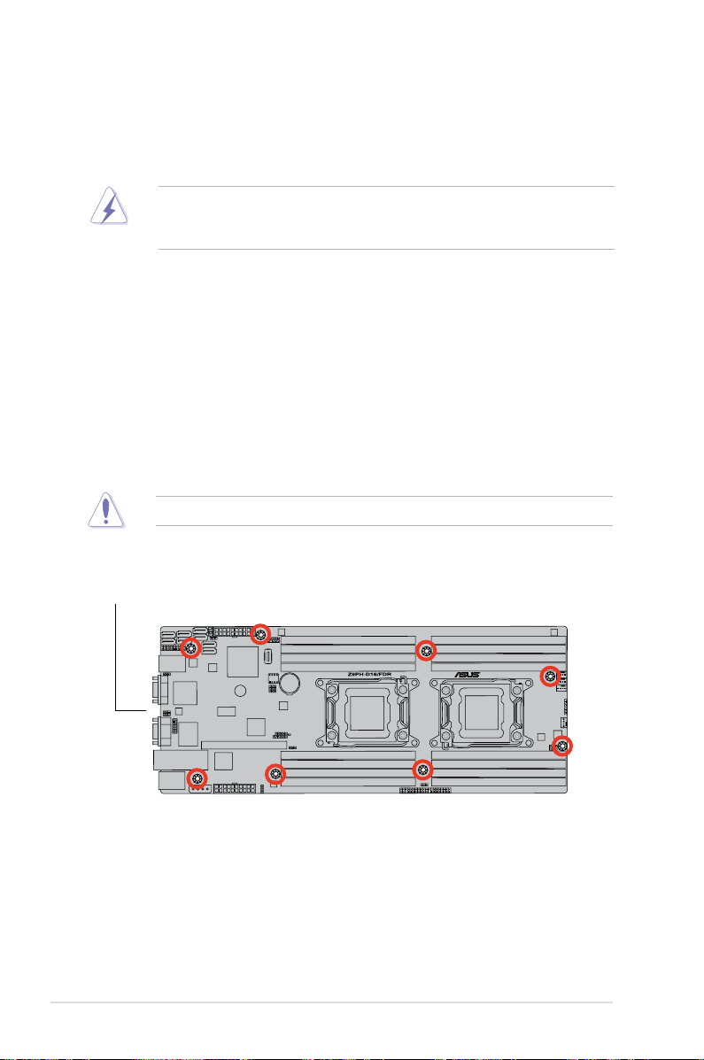
2.2.2 Screw holes
Place eight (8) screws into the holes indicated by circles to secure the motherboard
to the chassis.
DO NOT overtighten the screws! Doing so can damage the motherboard.
Place this side towards
the rear of the chassis
2-4 Chapter 2: Hardware information
Page 23
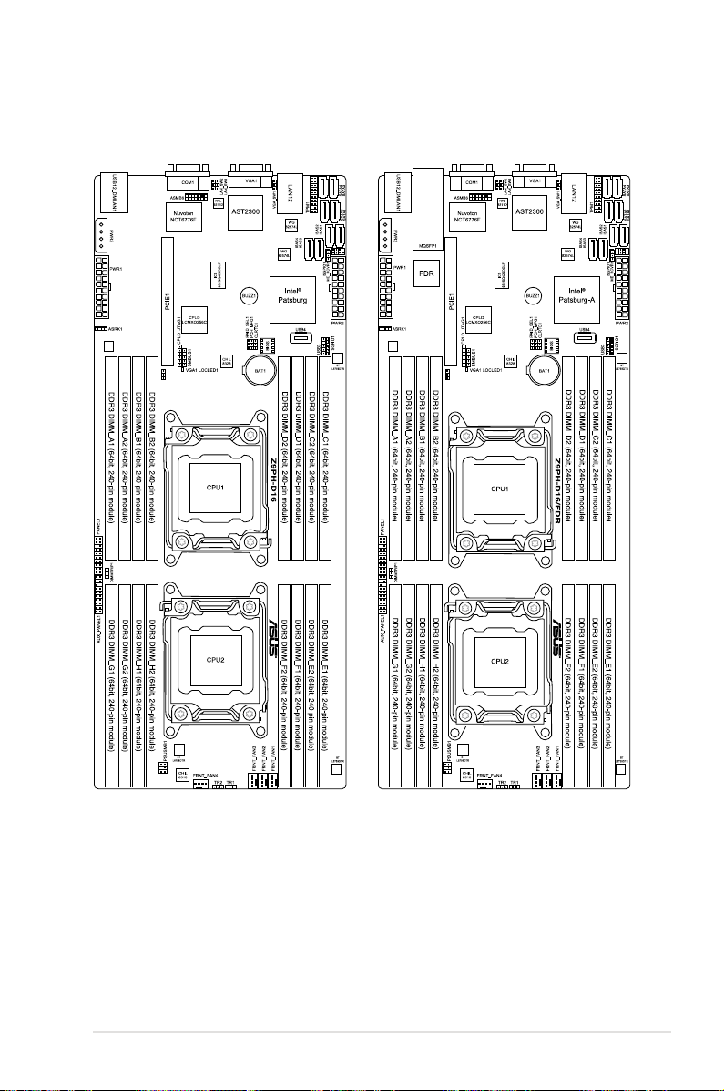
2.2.3 Motherboard layout
Z9PH-D16 Z9PH-D16/FDR
ASUS Z9PH-D16 Series 2-5
Page 24
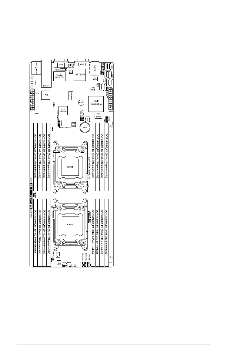
2.2.3 Motherboard layout
Q
Z9PH-D16/QDR
2-6 Chapter 2: Hardware information
Page 25
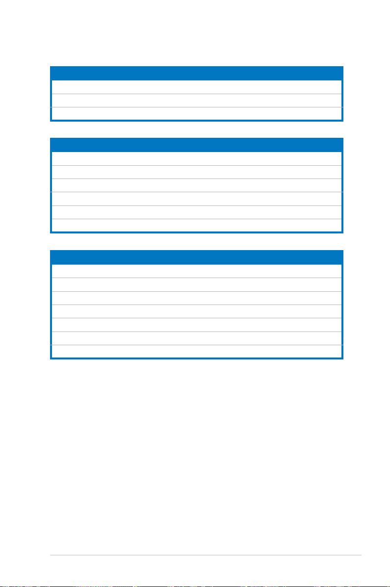
2.2.4 Layout contents
Slots/Socket Page
1. CPU sockets 2-9
2. DDR3 sockets
3. PCI Express x16 slots
Jumpers Page
1. Clear RTC RAM (CLRTC1) 2-22
2. VGA controller setting (3-pin VGA_SW1)
3. LAN controller setting (3-pin LAN_SW1, LAN_SW2)
4. LSI MegaRAID or Intel RSTe selection jumper (3-pin RAID_SEL1)
5. ME rmware force recovery setting (3-pin ME_RCVR1)
6. DDR3 thermal event setting (3-pin DIMMTRIP1)
Rear panel connectors Page
1. LAN 1 (RJ-45) port 2-26
2. DM_LAN 1 (RJ-45) port
3. LAN 2 (RJ-45) port
4. Video Graphics Adapter port
5. Serial (COM1) port
6. InniBand (QSFP) (Z9PH-D16/FDR and Z9PH-D16/QDR only)
7. USB 2.0 ports 1 and 2
2-15
2-19
2-23
2-23
2-24
2-24
2-25
2-26
2-26
2-26
2-26
2-26
2-26
ASUS Z9PH-D16 Series 2-7
Page 26

Internal connectors Page
1. Serial ATA connectors
2. ISAS connectors (7-pin ISAS1–4 [Gray])
3. USB connector (5-1 pin USB3; A-Type USB4)
4. Front fan connectors
5. Serial General Purpose Input/Output connector
6. Serial General Purpose Input/Output connector
7. ASMB6 header (ASMB6)
8. Thermal sensor cable connectors (3-pin TR1, TR2)
9. TPM connector (20-1 pin TPM1)
10. Power Supply SMBus connector (6-1 pin PSUSMB1)
11. Proprietary power connectors
12. System panel connector (20-pin PANEL1 [White])
13. Auxiliary panel connector (20-pin AUX_PANEL1 [Black])
(7-pin SATA1-2 [Lght blue], SATA3–4 [Black])
(4-pin FRNT_FAN1, FRNT_FAN2, FRNT_FAN3, FRNT_FAN4)
(6-1 pin SGPIO1)
(8-1 pin ISGPIO1)
(20-pin PWR1, 20-pin PWR2, 4-pin PWR3)
2-27
2-27
2-28
2-28
2-29
2-29
2-30
2-31
2-31
2-32
2-33
2-34
2-35
Internal LEDs
1. CPU WARNING LED (ERR_CPU1, ERR_CPU 2)
2. BMC LED (BMC_LED1)
2-8 Chapter 2: Hardware information
Page
2-34
2-34
Page 27
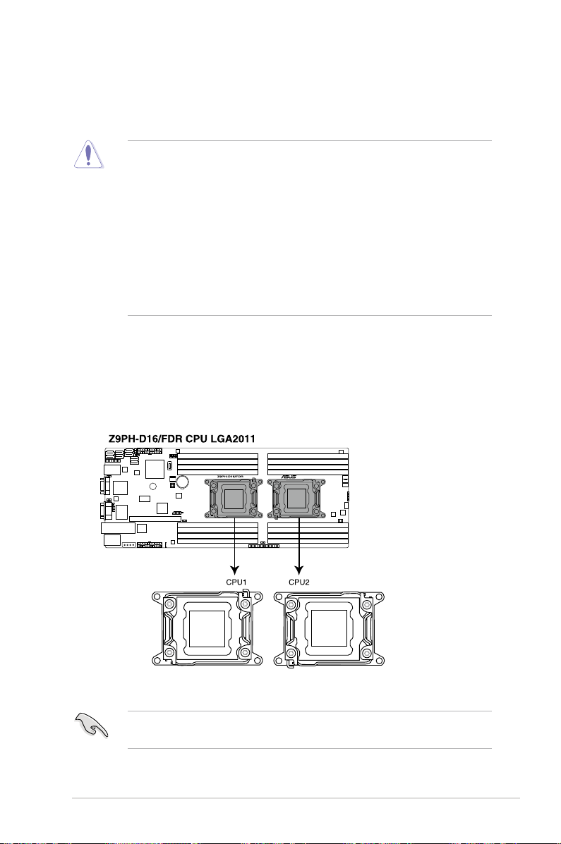
2.3 Central Processing Unit (CPU)
The motherboard comes with a surface mount LGA2011 socket designed for the
Intel® Xeon E5-2600 family processor.
• Upon purchase of the motherboard, ensure that the PnP cap is on
the socket and the socket contacts are not bent. Contact your retailer
immediately if the PnP cap is missing, or if you see any damage to the PnP
cap/socket contacts/motherboard components. ASUS will shoulder the cost
of repair only if the damage is shipment/transit-related.
• Keep the cap after installing the motherboard. ASUS will process Return
Merchandise Authorization (RMA) requests only if the motherboard comes
with the cap on the LGA2011 socket.
• The product warranty does not cover damage to the socket contacts
resulting from incorrect CPU installation/removal, or misplacement/loss/
incorrect removal of the PnP cap.
2.3.1 Installing the CPU
To install a CPU:
1. Locate the CPU socket on the motherboard.
Before installing the CPU, ensure that the socket box is facing toward you and
the load lever is on your left.
ASUS Z9PH-D16 Series 2-9
Page 28
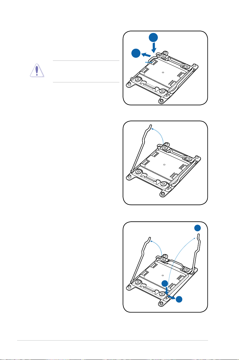
2. Press the left load lever with your
B
A
E
D
C
thumb (A), then move it to the left
(B) until it is released from the
retention tab.
To prevent damage to the socket
pins, do not remove the PnP cap
unless you are installing a CPU.
3. Slightly lift the load lever in the
direction of the arrow.
Load lever
4. Press the right load lever with your
thumb (C), then move it to the right
(D) until it is released from the
retention tab. Lift the load lever in
the direction of the arrow (E).
2-10 Chapter 2: Hardware information
Page 29
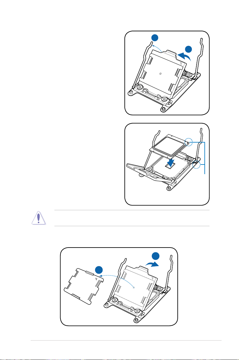
I
H
G
F
5. Push the left load lever (F) to lift the
load plate (G).
6. Position the CPU over the socket,
ensuring that the triangle mark is on
the top-right corner of the socket.
Triangle
mark
The CPU ts in only one correct orientation. DO NOT force the CPU into the
socket to prevent bending the connectors on the socket and damaging the CPU!
7. Remove the PnP cap (H) from the CPU socket and close the load plate (I).
ASUS Z9PH-D16 Series 2-11
Page 30
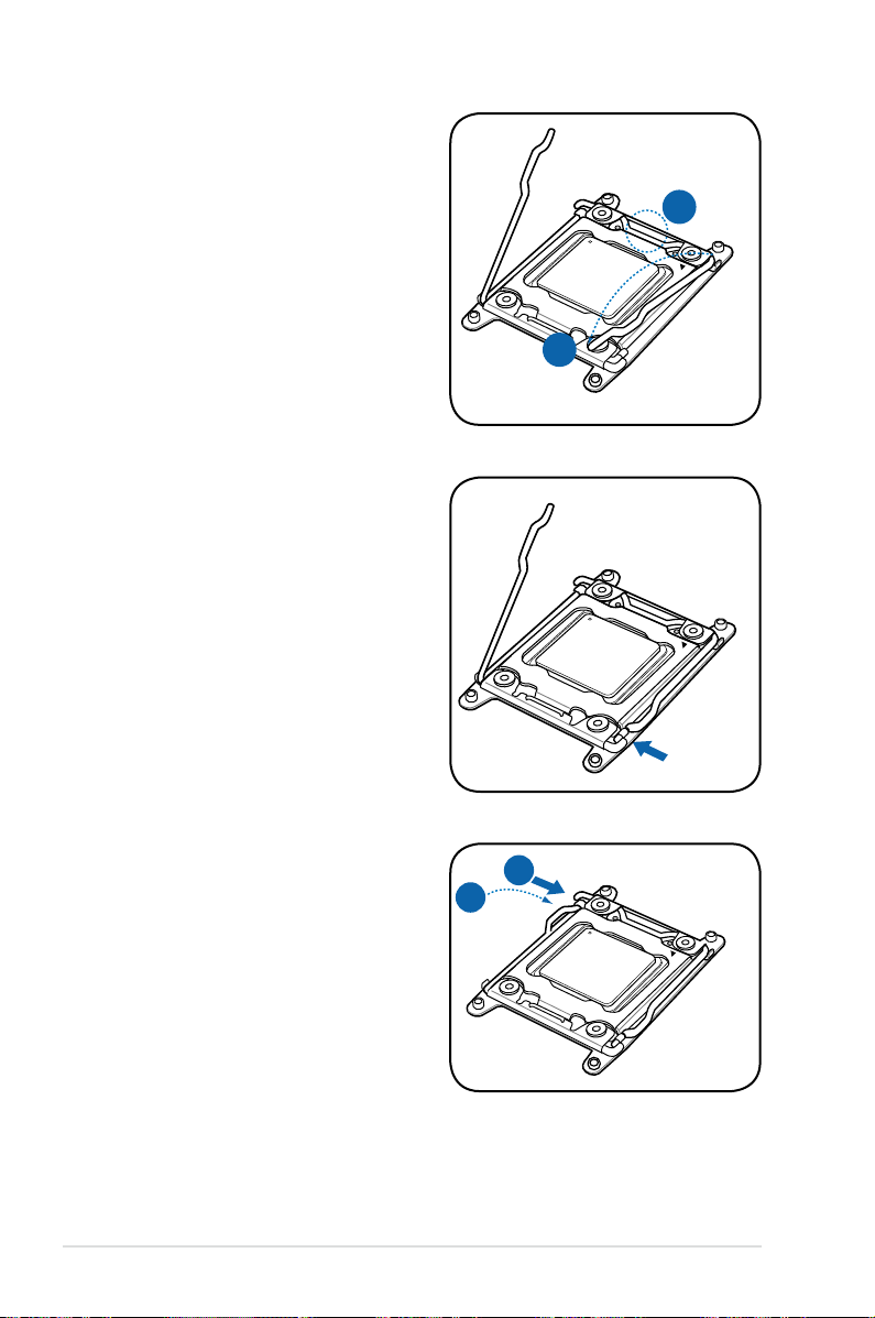
K
J
8. Push down the right load lever (J),
M
L
ensuring that the edge of the load
plate is xed by the lever (K).
9. Insert the right load lever under the
retention tab.
10. Push down the left load lever (L),
and then insert the lever under the
retention tab (M).
2-12 Chapter 2: Hardware information
Page 31
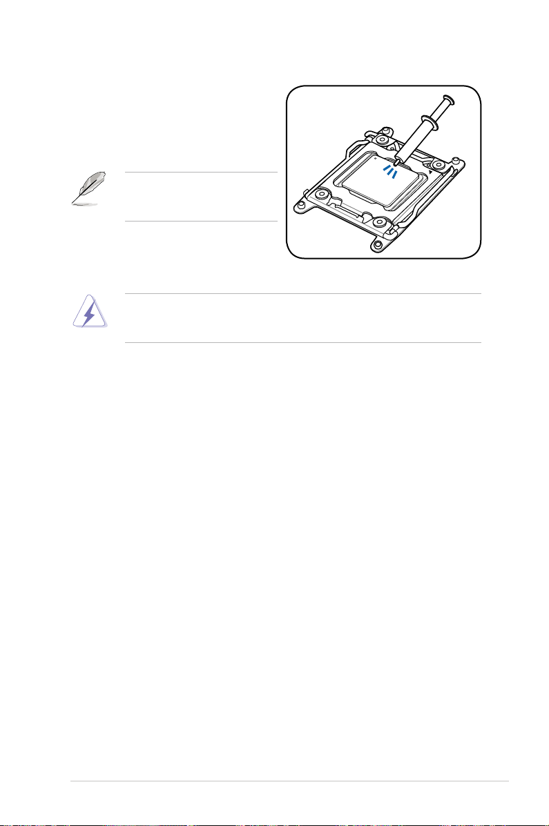
11. Apply some Thermal Interface
Material to the exposed area of
the CPU that the heatsink will be
in contact with, ensuring that it is
spread in an even thin layer.
Some heatsinks come with preapplied thermal paste. If so, skip
this step.
The Thermal Interface Material is toxic and inedible. DO NOT eat it. If it
gets into your eyes or touches your skin, wash it off immediately, and seek
professional medical help.
ASUS Z9PH-D16 Series 2-13
Page 32
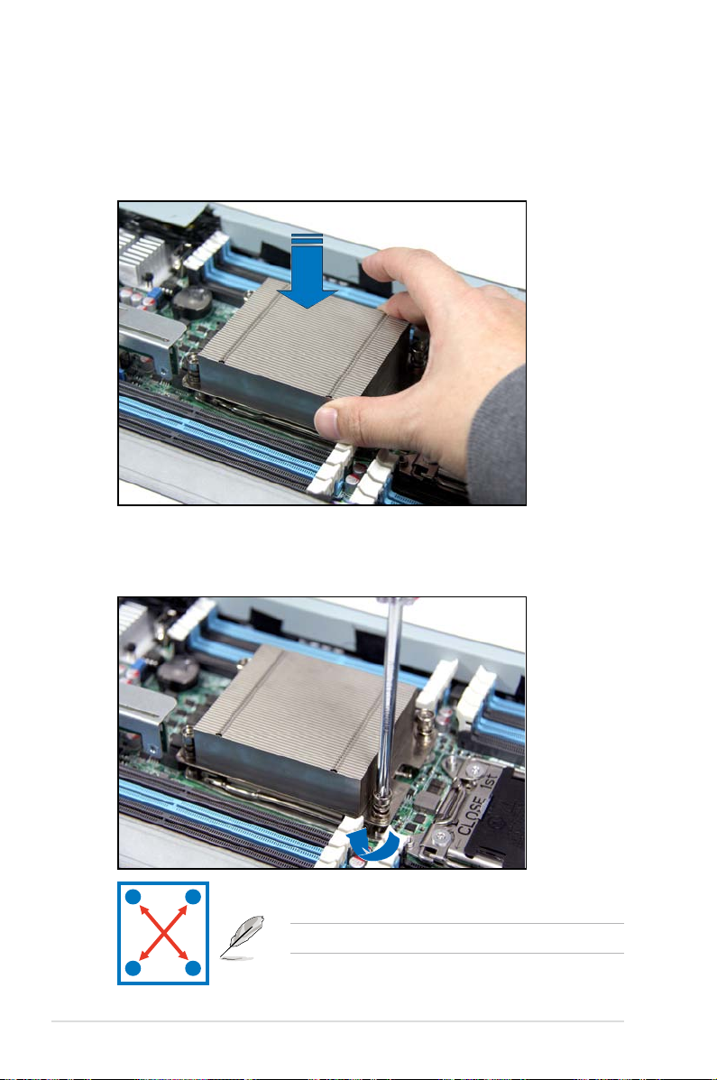
2.3.2 Installing the CPU heatsink
To install the CPU heatsink:
1. Place the heatsink on top of the installed CPU, ensuring that the four
fasteners match the holes on the motherboard.
2. Twist each of the four screws with a Philips (cross) screwdriver just enough to
attach the heatsink to the motherboard. When the four screws are attached,
tighten them one by one to completely secure the heatsink.
A
B
2-14 Chapter 2: Hardware information
B
Tighten the four heatsink screws in a diagonal sequence.
A
Page 33
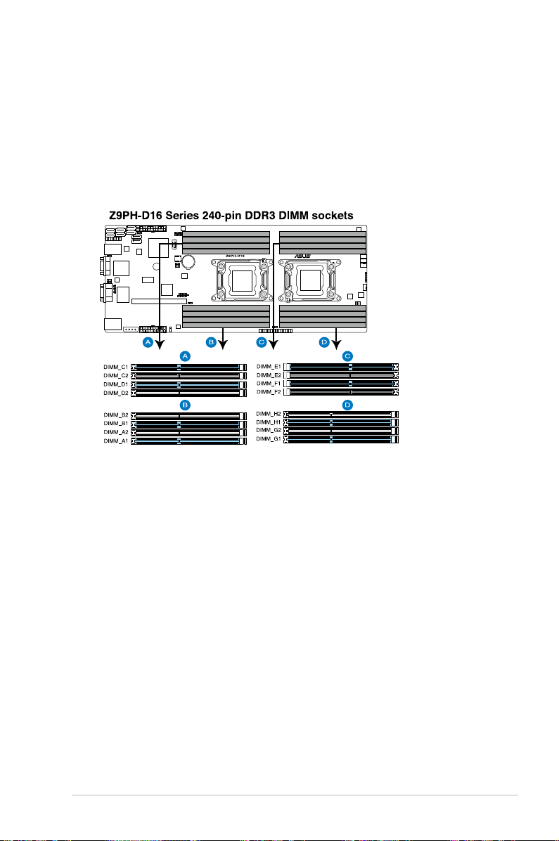
2.4 System memory
2.4.1 Overview
The motherboard comes with sixteen (16) Double Data Rate 3 (DDR3) Dual Inline
Memory Modules (DIMM) sockets.
The gure illustrates the location of the DDR3 DIMM sockets:
ASUS Z9PH-D16 Series 2-15
Page 34
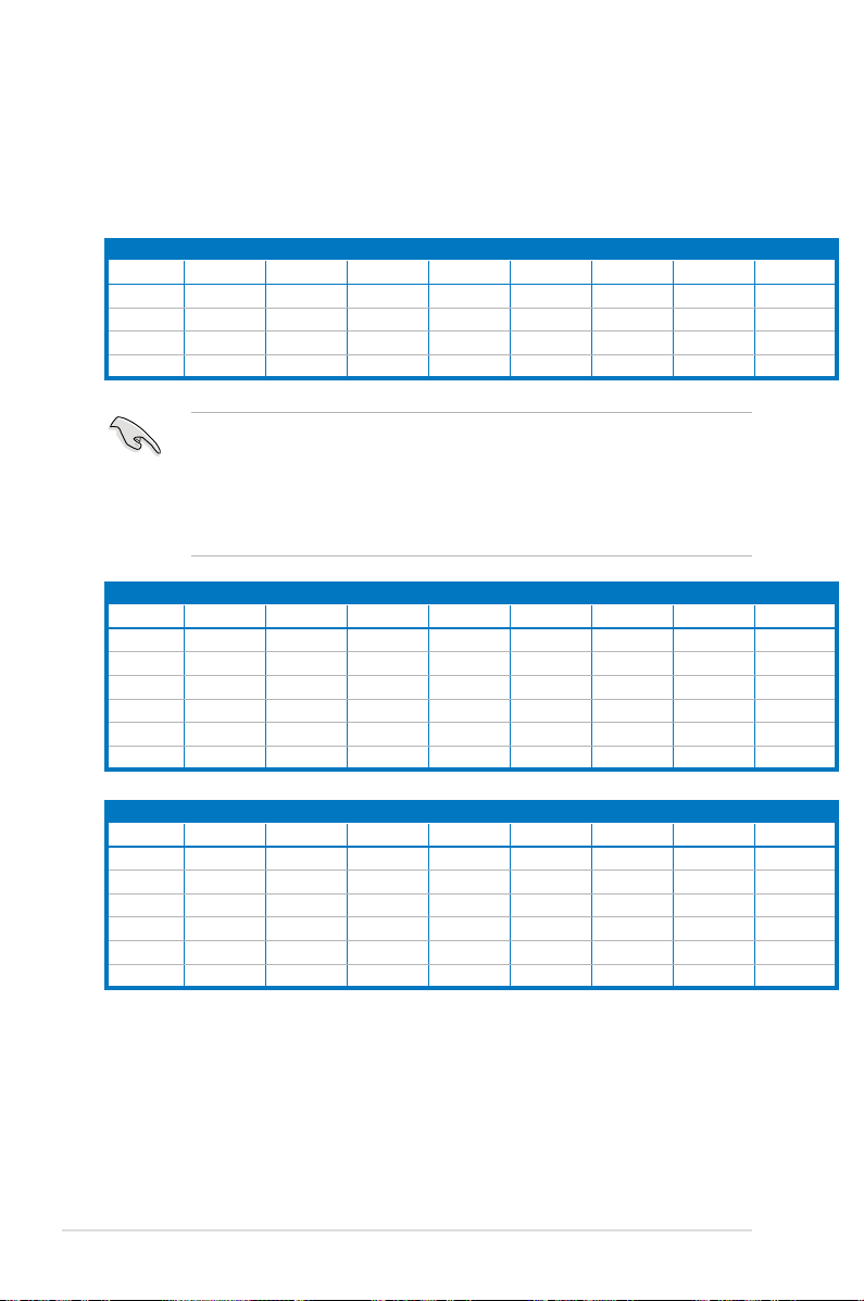
2.4.2 Memory Congurations
You may install 1GB, 2GB, 4GB, 8GB, 16GB* RDIMMs or
with ECC/Non-ECC UDIMMs or
8GB, 16GB and 32GB* LR-DIMMs into the DIMM
sockets using the memory congurations in this section.
1 CPU Conguration (must on CPU1)
DIMM_A2 DIMM_A1 DIMM_B2 DIMM_B1 DIMM_C2 DIMM_C1 DIMM_D2 DIMM_D1
1 DIMMs
2 DIMMs
4 DIMMs
8 DIMMs
2 CPU Conguration
1 DIMMs
2 DIMMs
4 DIMMs
8 DIMMs
12 DIMMs
16 DIMMs
X X X X X X X X
• *Refer to ASUS Server AVL for latest update.
• Start installing the DIMMs from slot A1 and B1 (light blue).
• Always install DIMMs with the same CAS latency. For optimum
compatibility, it is recommended that you obtain memory modules from the
same vendor.
DIMM_A2 DIMM_A1 DIMM_B2 DIMM_B1 DIMM_C2 DIMM_C1 DIMM_D2 DIMM_D1
X X X X X X
X X X X X X X X
X
X X
X X X X
X
X
X X
X X X X
1GB, 2GB, 4GB and 8GB*
2 CPU Conguration
DIMM_E2 DIMM_E1 DIMM_F2 DIMM_F1 DIMM_G2 DIMM_G1 DIMM_H2 DIMM_H1
1 DIMMs
2 DIMMs
4 DIMMs
8 DIMMs
12 DIMMs
16 DIMMs
2-16 Chapter 2: Hardware information
X X X X X X
X X X X X X X X
X
X X
X X X X
Page 35
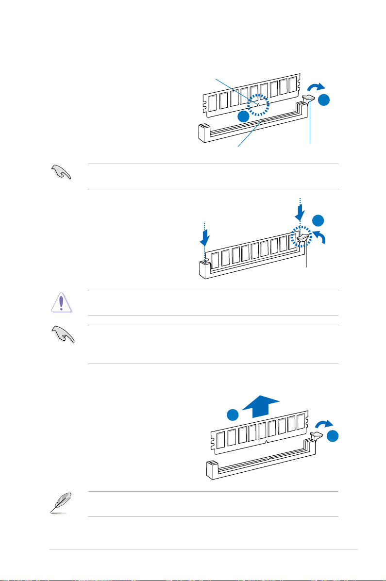
2.4.3 Installing a DIMM on a single clip DIMM socket
1. Unlock a DIMM socket by pressing
DIMM notch
the retaining clip outward.
2. Align a DIMM on the socket
such that the notch on the DIMM
matches the DIMM slot key on the
socket.
A DIMM is keyed with a notch so that it ts in only one direction. DO NOT force
a DIMM into a socket in the wrong direction to avoid damaging the DIMM.
3. Hold the DIMM by both of its ends,
then insert the DIMM vertically
into the socket. Apply force to both
ends of the DIMM simultaneously
until the retaining clip snaps back
into place, and the DIMM cannot
be pushed in any further to ensure
proper sitting of the DIMM.
Always insert the DIMM into the socket VERTICALLY to prevent DIMM notch
damage.
• To install two or more DIMMs, refer to the user guide bundled in the
motherboard package.
• Refer to the user guide for qualied vendor lists of the memory modules.
2
DIMM slot key
1
Unlocked retaining clip
3
Locked Retaining Clip
Removing a DIMM from a single clip DIMM socket
1. Press the retaining clip outward to
unlock the DIMM.
2. Remove the DIMM from the socket.
Support the DIMM lightly with your ngers when pressing the retaining clips.
The DIMM might get damaged when it ips out with extra force.
ASUS Z9PH-D16 Series 2-17
2
1
Page 36

2.5 Expansion slots
In the future, you may need to install expansion cards. The following subsections
describe the slots and the expansion cards that they support.
Ensure to unplug the power cord before adding or removing expansion cards.
Failure to do so may cause you physical injury and damage motherboard
components.
2.5.1 Installing an expansion card
To install an expansion card:
1. Before installing the expansion card, read the documentation that came with
it and make the necessary hardware settings for the card.
2. Remove the system unit cover (if your motherboard is already installed in a
chassis).
3. Remove the bracket opposite the slot that you intend to use. Keep the screw
for later use.
4. Align the card connector with the slot and press rmly until the card is
completely seated on the slot.
5. Secure the card to the chassis with the screw you removed earlier.
6. Replace the system cover.
2.5.2 Conguring an expansion card
After installing the expansion card, congure it by adjusting the software settings.
1. Turn on the system and change the necessary BIOS settings, if any. See
Chapter 4 for information on BIOS setup.
2. Assign an IRQ to the card. Refer to the tables on the next page.
3. Install the software drivers for the expansion card.
When using PCI cards on shared slots, ensure that the drivers support “Share
IRQ” or that the cards do not need IRQ assignments. Otherwise, conicts will
arise between the two PCI groups, making the system unstable and the card
inoperable.
2-18 Chapter 2: Hardware information
Page 37

2.5.3 Interrupt assignments
Standard Interrupt assignments
IRQ Priority Standard function
0 1 System Timer
1 2 Keyboard Controller
2 - Programmable Interrupt
4* 12 Communications Port (COM1)
5* 13 --
6 14 Floppy Disk Controller
7* 15 --
8 3 System CMOS/Real Time Clock
9* 4 ACPI Mode when used
10* 5 IRQ Holder for PCI Steering
11* 6 IRQ Holder for PCI Steering
12* 7 PS/2 Compatible Mouse Port
13 8 Numeric Data Processor
14* 9 Primary IDE Channel
15* 10 Secondary IDE Channel
* These IRQs are usually available for ISA or PCI devices.
2.5.4 PCI Express x16 slot (x16 link)
The onboard PCI Express x16 slot provides x16 link to the Intel
family processor. This slot supports VGA cards and various server class high
performance add-on cards.
®
Xeon E5-2600
PCIEx16 slot (x16 link)
When installing the motherboard to a 1U/2U rackmount server system, rst
install the expansion card using an optional PCIe x16 riser card, then install the
riser card along with the expansion card to the onboard PCI Express x16 slot.
ASUS Z9PH-D16 Series 2-19
Page 38

2.5.5 Installing ASMB6 management board
Follow the steps below to install an optional ASMB6 management board on your
motherboard.
1. Locate the ASMB6 header on the
motherboard.
2. Orient and press the ASMB6
management card in place.
2-20 Chapter 2: Hardware information
Page 39
2.6 Jumpers
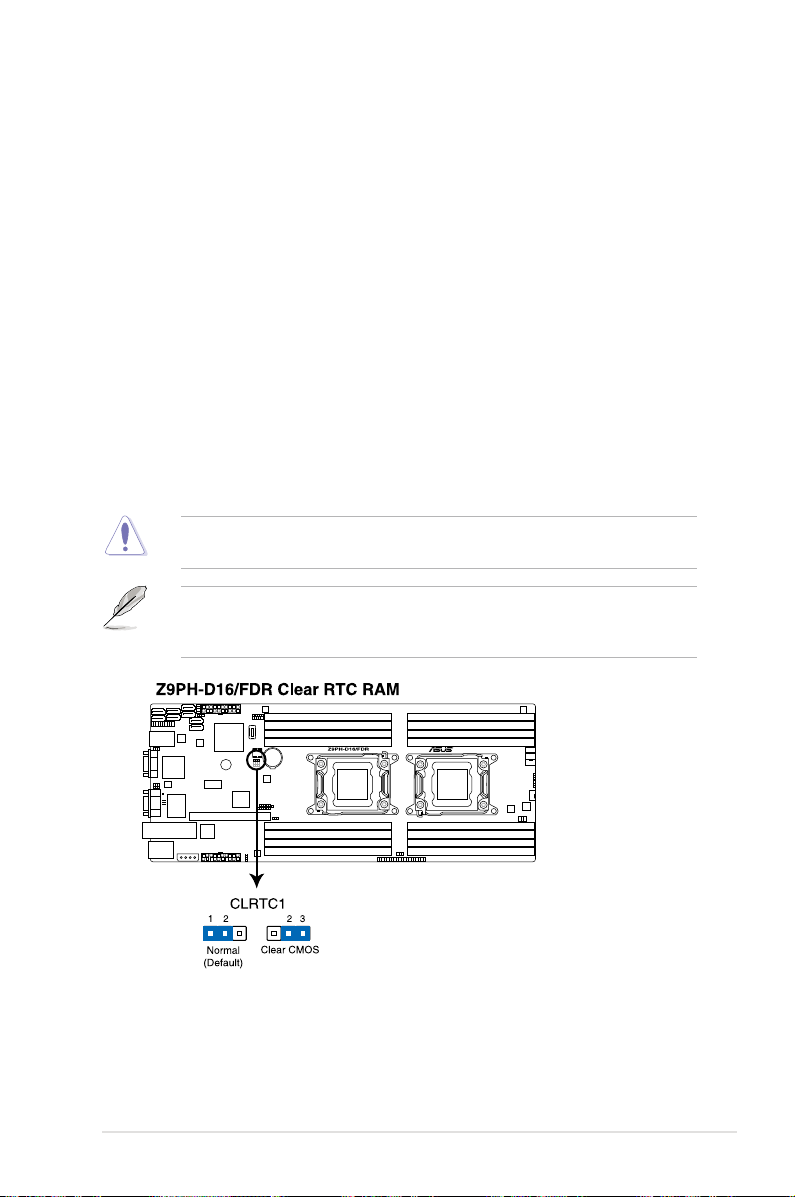
1. Clear RTC RAM (CLRTC1)
This jumper allows you to clear the Real Time Clock (RTC) RAM in CMOS.
You can clear the CMOS memory of date, time, and system setup parameters
by erasing the CMOS RTC RAM data. The onboard button cell battery
powers the RAM data in CMOS, which include system setup information such
as system passwords.
To erase the RTC RAM:
1. Turn OFF the computer and unplug the power cord.
2. Move the jumper cap from pins 1–2 (default) to pins 2–3. Keep the cap
on pins 2–3 for about 5–10 seconds, then move the cap back to pins 1–
2.
3. Plug the power cord and turn ON the computer.
4. Hold down the <Del> key during the boot process and enter BIOS setup
to re-enter data.
Except when clearing the RTC RAM, never remove the cap on CLRTC jumper
default position. Removing the cap will cause system boot failure!
If the steps above do not help, remove the onboard battery and move the
jumper again to clear the CMOS RTC RAM data. After the CMOS clearance,
reinstall the battery.
ASUS Z9PH-D16 Series 2-21
Page 40
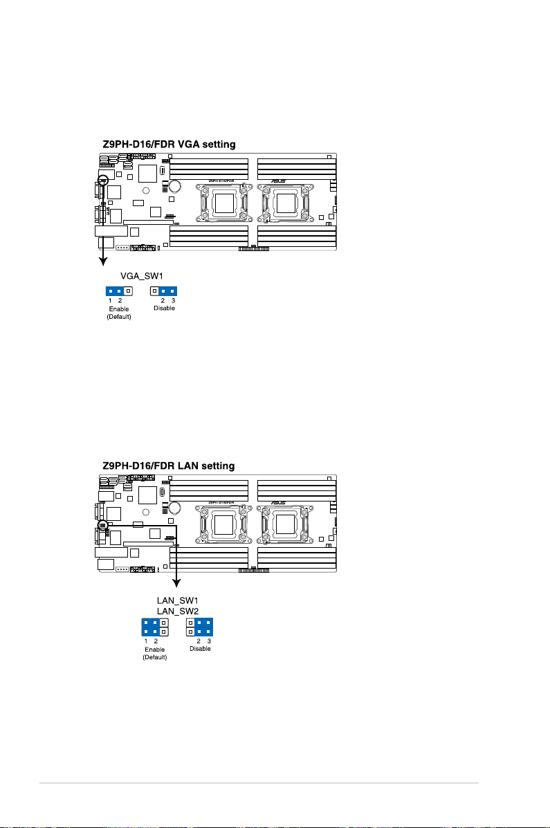
2. VGA controller setting (3-pin VGA_SW1)
This jumper allows you to enable or disable the onboard VGA controller. Set
to pins 1–2 to activate the VGA feature.
3. LAN controller setting (3-pin LAN_SW1, LAN_SW2)
These jumpers allow you to enable or disable the onboard Intel
®
Intel
82574LGigabit LAN controllers. Set to pins 1–2 to activate the Gigabit LAN
feature.
2-22 Chapter 2: Hardware information
Page 41
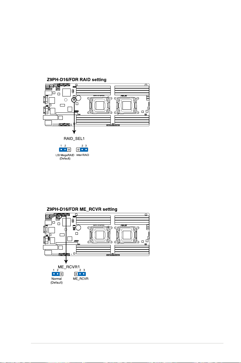
4. LSI MegaRAID or Intel RSTe selection jumper (3-pin RAID_SEL1)
This jumper allows you to select the PCH SATA RAID mode to use LSI
MegaRAID software or Intel® Rapid Storage Technology enterprise 3.0 RAID.
Place the jumper caps over pins 1–2 if you want to use the LSI MegaRAID
software RAID Utility (default); otherwise, place the jumper caps to pins 2–3
to use the Intel® Rapid Storage Technology Enterprise Option ROM Utility.
5. ME rmware force recovery setting (3-pin ME_RCVR1)
This jumper allows you to quickly recover the Intel Management Engine (ME)
rmware when it becomes corrupted.
ASUS Z9PH-D16 Series 2-23
Page 42
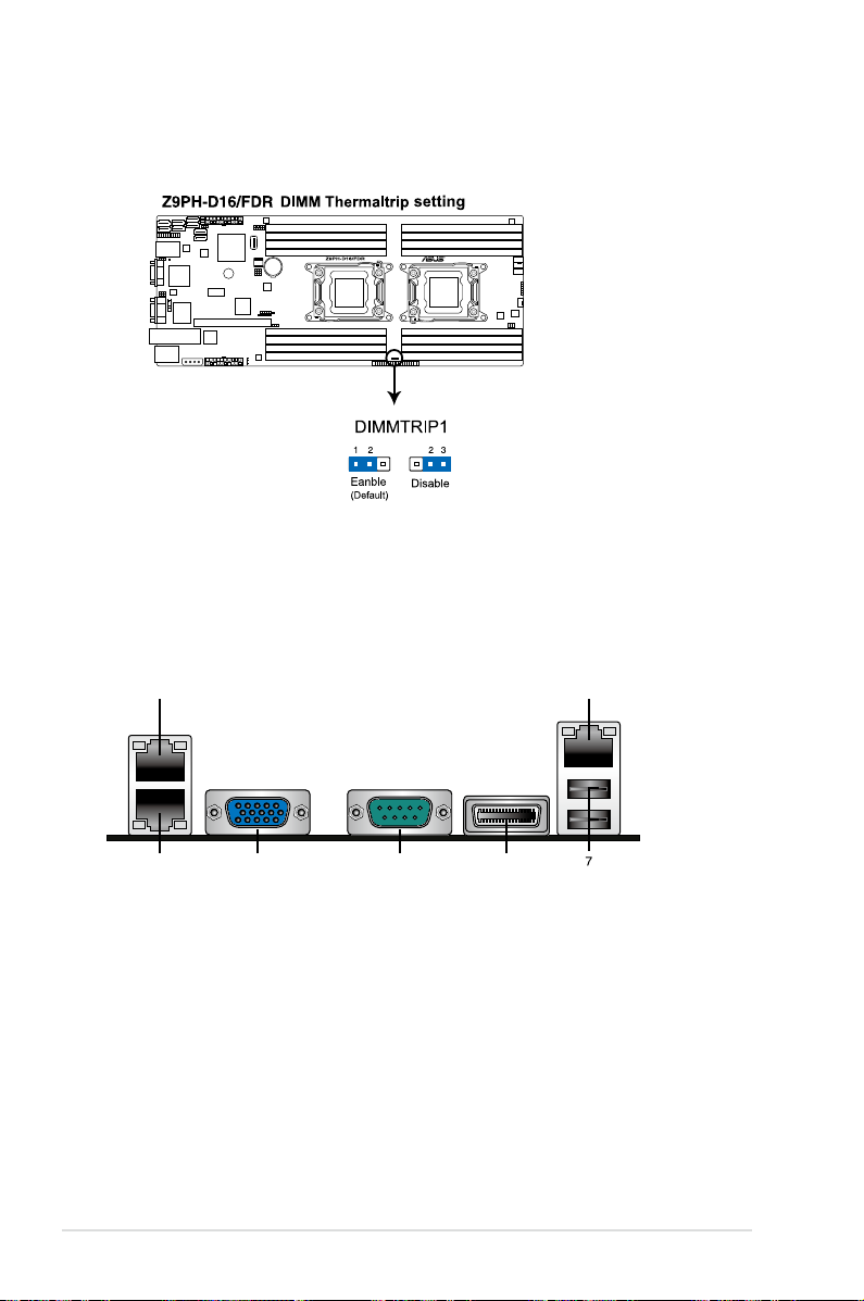
6. DIMM thermal trip Setting (3-pin DIMMTRIP1)
2
4 5 6
1
3
This jumper allows you to enable(default) or disable DIMM thermal trip.
2.7 Connectors
2.7.1 Rear panel connectors
1. LAN 2 (RJ-45) port.
This port allows Gigabit connection to a Local Area
Network (LAN) through a network hub. Refer to the table below for the LAN
port LED indications.
2. DM_LAN 1 (RJ-45) port.
This port allows Gigabit connection to a Local Area
Network (LAN) through a network hub for dedicated BMC Mamagement
function. Refer to the table below for the DM_LAN1 and LAN port LED
indications.
3. LAN 1 (RJ-45) port.
Network (LAN) through a network hub. Refer to the table below for the LAN
This port allows Gigabit connection to a Local Area
port LED indications.
2-24 Chapter 2: Hardware information
Page 43
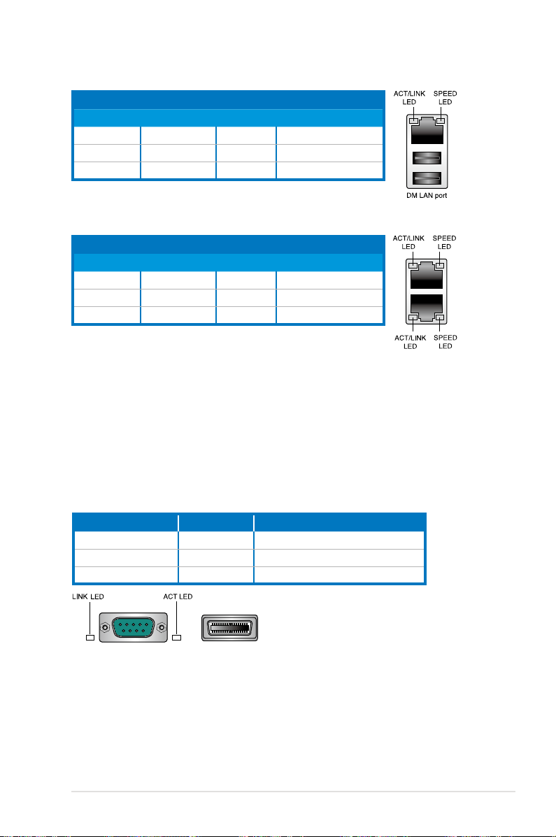
DM_LAN1 port LED indications
Activity/Link LED Speed LED
Status Description Status Description
OFF No link OFF 10 Mbps connection
ORANGE Linked ORANGE 100 Mbps connection
BLINKING Data activity GREEN 1 Gbps connection
LAN port LED indications
Activity/Link LED Speed LED
Status Description Status Description
OFF No link OFF 10 Mbps connection
GREEN Linked ORANGE 100 Mbps connection
BLINKING Data activity GREEN 1 Gbps connection
4. Video Graphics Adapter port.
This port is for a VGA monitor or other VGA-
compatible devices.
5. Serial (COM1) port.
This 9-pin communication port is for pointing devices or
other serial devices.
6. InniBand (QSFP).
(Z9PH-D16/FDR and Z9PH-D16/QDR only)
allows connection with a QSFP cable to an InniBand switch.
InniBand (QSFP) indications
Activity/Link LED Link LED Description
OFF OFF No device
ORANGE GREEN Device plugged in; Ready
ORANGE BLINKING GREEN Device plugged in; Data transmitting
7. USB 2.0 ports 1 and 2.
available for connecting USB 2.0 devices.
These two 4-pin Universal Serial Bus (USB) ports are
This port
ASUS Z9PH-D16 Series 2-25
Page 44

2.7.2 Internal connectors
1. Serial ATA connectors (7-pin SATA1-2 [Light blue], SATA3–4 [Black])
(SATA 6Gb/s: 7-pin SATA1-2 [Light blue])
(SATA 3Gb/s: 7-pin SATA3-4 [Black])
These connectors, controlled by Intel® C602 chipset, are for the Serial ATA
signal cables for Serial ATA hard disk drives.
The actual data transfer rate depends on the speed of Serial ATA hard disks
installed.
2-26 Chapter 2: Hardware information
Page 45

2. SATA connector - ISAS connectors (7-pin ISAS1–4 [Gray])
Supported by the Intel® C602 PCH. ISAS 1-4 connectors can connect to serial
ATA 3Gb/s hard disk drives.
The actual data transfer rate depends on the speed of SATA hard disks installed.
For details on the Intel® Rapid Storage Technology utility, please refer to
6 RAID Conguration
Chapter
ASUS Z9PH-D16 Series 2-27
Page 46
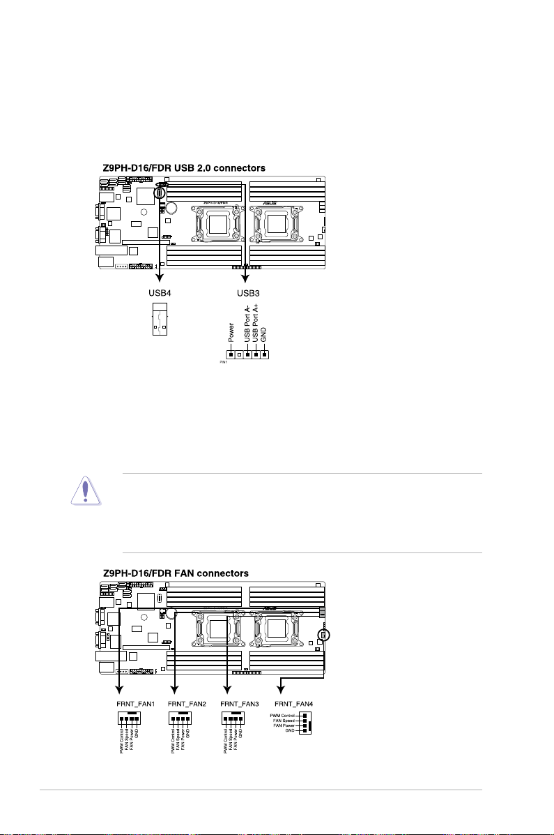
3. USB connector (5-1 pin USB3; A-Type USB4)
These connectors are for USB 2.0 ports. Connect the USB module cables
to connectors USB3, then install the modules to a slot opening at the
back of the system chassis. These USB connectors comply with USB 2.0
specication that supports up to 480 Mbps connection speed.
4. Front fan connectors
(4-pin FRNT_FAN1, FRNT_FAN2, FRNT_FAN3, FRNT_FAN4)
The fan connectors support cooling fans of 350 mA–740 mA (8.88 W max.)
or a total of 3.15 A–6.66 A (53.28 W max.) at +12V. Connect the fan cables to
the fan connectors on the motherboard, ensuring that the black wire of each
cable matches the ground pin of the connector.
• DO NOT forget to connect the fan cables to the fan connectors. Insufcient
air ow inside the system may damage the motherboard components.
• These are not jumpers! DO NOT place jumper caps on the fan connectors!
• All fans feature the ASUS Smart Fan technology.
2-28 Chapter 2: Hardware information
Page 47
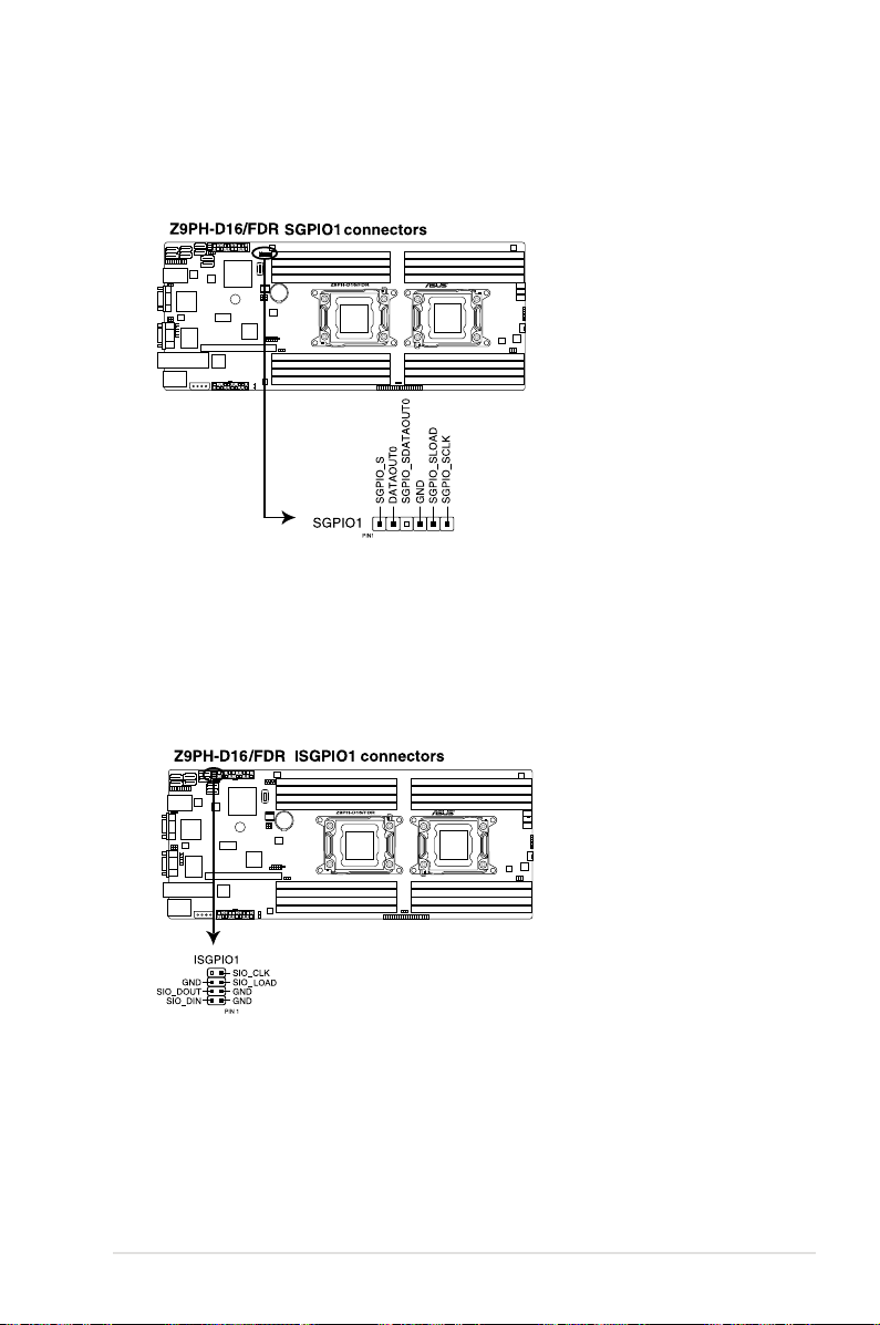
5. Serial General Purpose Input/Output connector (6-1 pin SGPIO1)
This connector is used for the SGPIO peripherals for the LSI MegaRAID and
Intel Matrix RAID SATA LED.
6. Serial General Purpose Input/Output connector (8-1 pin ISGPIO1)
This connector is used for the SGPIO peripherals for the LSI MegaRAID and
Intel Matrix RAID SATA LED.This connector is used for SCU.
ASUS Z9PH-D16 Series 2-29
Page 48
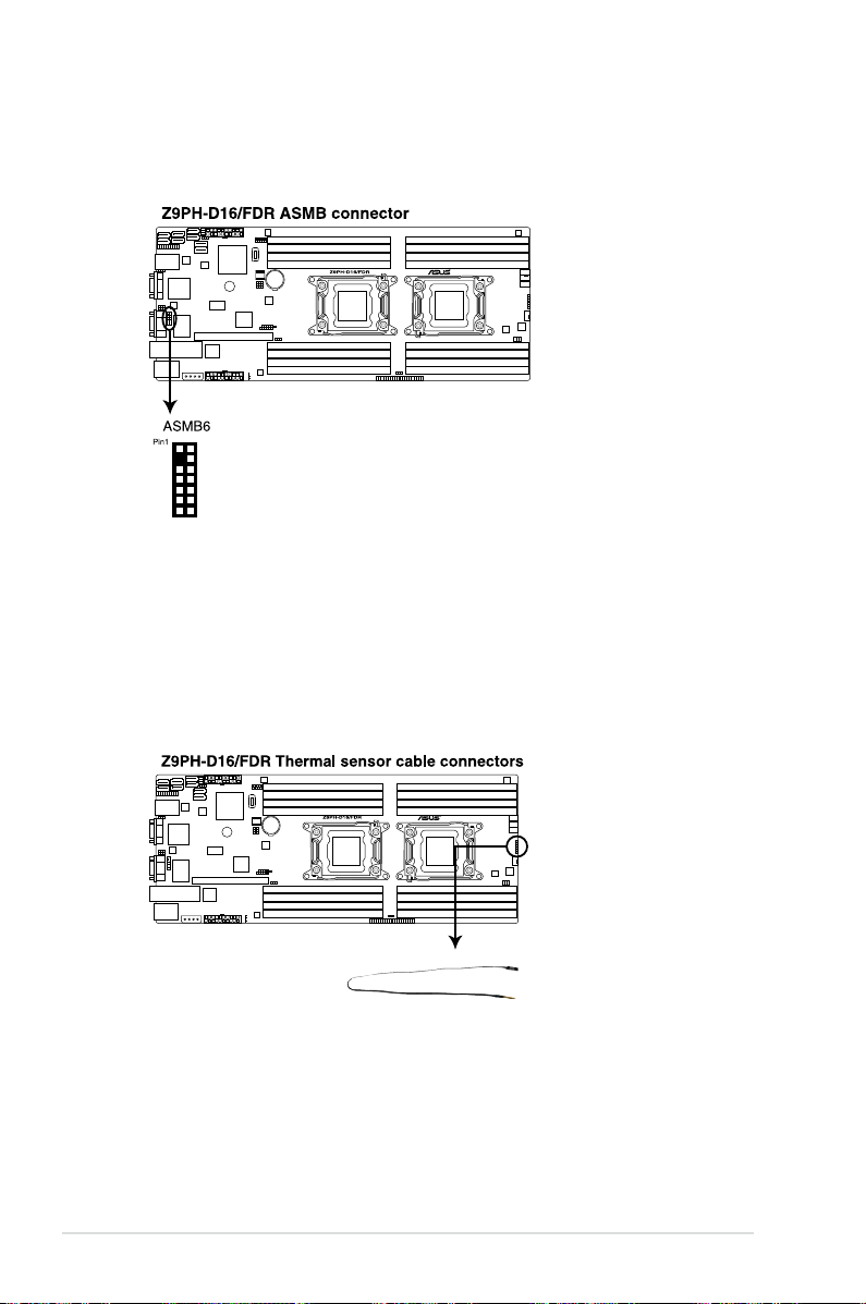
7. ASMB6 header (ASMB6)
The ASMB6 connector on the motherboard supports an ASUS
®
Server
Management Board 6 Series.
8. Thermal sensor cable connectors (3-pin TR1, TR2)
These connectors are for temperature monitoring. Connect the thermal
sensor cables to these connectors and place the other ends to the devices,
which you want to monitor temperature.
Please go to BIOS setup to change the default setting of TR1/TR2 from
“disabled“ to “enabled“ before using the thermal sensor cable.
2-30 Chapter 2: Hardware information
Page 49

BMC_SYNC
12C1SCL_PB
GND
PSU_ALERT#
12C1SDA_PB
9. TPM connector (20-1 pin TPM)
This connector supports a Trusted Platform Module (TPM) system, which can
securely store keys, digital certicates, passwords, and data. A TPM system
also helps enhance network security, protects digital identities, and ensures
platform integrity.
10. Power Supply SMBus connector (6-1 pin PSUSMB1)
This connector allows you to connect SMBus (System Management Bus) to
the power supply unit to read PSU information. Devices communicate with an
SMBus host and/or other SMBus devices using the SMBus interface.
ASUS Z9PH-D16 Series 2-31
Page 50
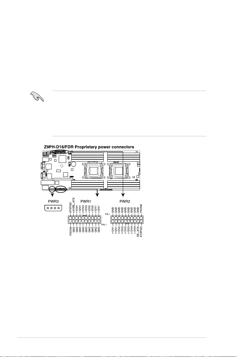
11. Proprietary power connectors
(20-pin PWR1, 20-pin PWR2, 4-pin PWR3)
These connectors are for Proprietary power supply plugs. The power supply
plugs are designed to t these connectors in only one orientation. Orient the
connectors and push down rmly until they completely t.
The 4-pin PWR3 is designed for hard disk drives power supply. DO NOT
connect other 4-pin power connectors of the power supply unit (PSU) to this
connector.
• Connect either one of the 20-pin power connectors to boot up the system.
• Use of a PSU with a higher power output is recommended when
conguring a system with more power-consuming devices. The system
may become unstable or may not boot up if the power is inadequate.
• USE THE PROPRIETARY POWER SUPPLY ONLY and ensure that your
PSU can provide at least the minimum power required by your system.
2-32 Chapter 2: Hardware information
Page 51

12. System panel connector (20-pin PANEL1 [White])
This connector supports several chassis-mounted functions.
1. System power LED (3-pin PLED)
This 3-pin connector is for the system power LED. Connect the chassis
power LED cable to this connector. The system power LED lights up
when you turn on the system power, and blinks when the system is in
sleep mode.
2. Message LED (2-pin MLED)
This 2-pin connector is for the message LED cable that connects to
the front message LED. The message LED is controlled by Hardware
monitor to indicate an abnormal event occurance.
3. System warning speaker (4-pin SPEAKER)
This 4-pin connector is for the chassis-mounted system warning speaker.
The speaker allows you to hear system beeps and warnings.
4. Hard disk drive activity LED (2-pin HDDLED)
This 2-pin connector is for the HDD Activity LED. Connect the HDD
Activity LED cable to this connector. The IDE LED lights up or ashes
when data is read from or written to the HDD.
5. Proprietary power button/soft-off button (2-pin PWRSW)
This connector is for the system power button. Pressing the power
button turns the system on or puts the system in sleep or soft-off mode
depending on the BIOS settings. Pressing the power switch for more
than four seconds while the system is ON turns the system OFF.
6. Reset button (2-pin RESET)
This 2-pin connector is for the chassis-mounted reset button for system
reboot without turning off the system power.
ASUS Z9PH-D16 Series 2-33
Page 52
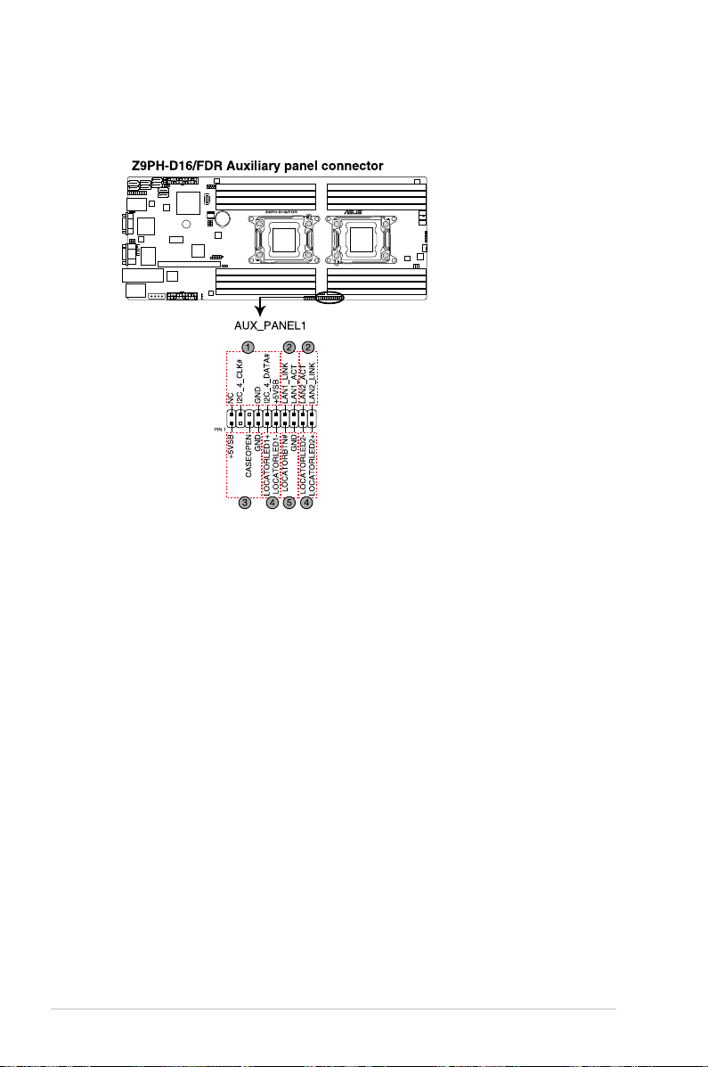
13. Auxiliary panel connector (20-pin AUX_PANEL1 [Black])
This connector is for additional front panel features including front panel
SMB, locator LED and switch, chassis intrusion, and LAN LEDs.
1. Front panel SMB (6-1 pin FPSMB)
These leads connect the front panel SMBus cable.
2. LAN activity LED (2-pin LAN1_LED, LAN2_LED
)
These leads are for Gigabit LAN activity LEDs on the front panel.
3. Chassis intrusion (4-1 pin CHASSIS)
These leads are for the intrusion detection feature for chassis with
intrusion sensor or microswitch. When you remove any chassis
component, the sensor triggers and sends a high-level signal to these
leads to record a chassis intrusion event. The default setting is short
CASEOPEN and GND pin by jumper cap to disable the function.
4. Locator LED (2-pin LOCATORLED1 and 2-pin LOCATORLED2)
These leads are for the locator LED1 and LED2 on the front panel.
Connect the Locator LED cables to these 2-pin connector. The LEDs will
light up when the Locator button is pressed.
5. Locator Button/Swich (2-pin LOCATORBTN)
These leads are for the locator button on the front panel. This button
queries the state of the system locator.
2-34 Chapter 2: Hardware information
Page 53

2.8 Internal LEDs
1. CPU warning LED (ERR_CPU1, ERR_CPU2)
The CPU warning LEDs light up to indicate an impending failure of the corresponding
CPU.
The warning LEDs function only when you install the ASUS ASMB6.
2. BMC LED(BMC_LED1)
The green heartbeat LED blinks per second to indicate that the ASMB6 is working
normally.
The heartbeat LED functions only when you install the ASUS ASMB6
•
Everytime after the AC power is replugged, you have to wait for about
•
30 seconds for the system to power up.
ASUS Z9PH-D16 Series 2-35
Page 54

2-36 Chapter 2: Hardware information
Page 55

This chapter describes the power up
sequence, and ways of shutting down the
system.
Chapter 3:
Powering up
3
Page 56

Chapter summary
3
3.1 Starting up for the rst time ........................................................ 3-3
3.2 Powering off the computer ..........................................................
3-4
ASUS Z9PH-D16 Series
Page 57

3.1 Starting up for the rst time
1. After making all the connections, replace the system case cover.
2. Be sure that all switches are off.
3. Connect the power cord to the power connector at the back of the system
chassis.
4. Connect the power to a power outlet that is equipped with a surge protector.
5. Turn on the devices in the following order:
a. Monitor
b. External storage devices (starting with the last device on the chain)
c. System power
6. After applying power, the system power LED on the system front panel case
lights up. For systems with ATX power supplies, the system LED lights up
when you press the ATX power button. If your monitor complies with “green”
standards or if it has a “power standby” feature, the monitor LED may light up
or switch between orange and green after the system LED turns on.
The system then runs the power-on self-test or POST. While the tests are
running, the BIOS beeps or additional messages appear on the screen. If you
do not see anything within 30 seconds from the time you turned on the power,
the system may have failed a power-on test. Check the jumper settings and
connections or call your retailer for assistance.
7. At power on, hold down the <Del> key to enter the BIOS Setup. Follow the
instructions in Chapter 4.
ASUS Z9PH-D16 Series 3-3
Page 58

3.2 Powering off the computer
3.2.1 Using the OS shut down function
If you are using Windows® 2008 Server:
1. Click the
and then click
2. From the
why you want to shut down the computer.
3. Ensure that the
4. If necessary, key in comments.
5. Click
OK
button, move the cursor to the triangle on the right of
Start
Shut Down
Shutdown Event Tracker
Planned
.
.
, select the option that best describes
check box is checked.
Log off
,
3.2.2 Using the dual function power switch
While the system is ON, pressing the power switch for less than four seconds puts
the system to sleep mode or to soft-off mode, depending on the BIOS setting.
3-4 Chapter 3: Powering up
Page 59

This chapter tells how to change the
system settings through the BIOS Setup
menus. Detailed descriptions of the BIOS
parameters are also provided.
Chapter 4:
BIOS setup
4
Page 60

Chapter summary
4
4.1 Managing and updating your BIOS ............................................ 4-3
4.2 BIOS setup program ....................................................................
4.3 Main menu ..................................................................................
4.4 Advanced menu .........................................................................
4.5 Server Mgmt menu .....................................................................
4.6 Event Logs menu .......................................................................
4.7 Boot menu ..................................................................................
4.8 Monitor menu .............................................................................
4.9 Security menu ............................................................................
4.10 Tool menu ...................................................................................
4.11 Exit menu ....................................................................................
4-7
4-10
4-11
4-36
4-39
4-41
4-43
4-44
4-45
4-46
ASUS Z9PH-D16 Series
Page 61

4.1 Managing and updating your BIOS
The following utilities allow you to manage and update the motherboard Basic
Input/Output System (BIOS) setup:
1.
ASUS CrashFree BIOS 3
(To recover the BIOS using a bootable USB ash
disk drive when the BIOS le fails or gets corrupted.)
2.
ASUS EZ Flash 2
3.
BUPDATER utility
(Updates the BIOS using a USB ash disk.)
(Updates the BIOS in DOS mode using a bootable USB
ash disk drive.)
Refer to the corresponding sections for details on these utilities.
Save a copy of the original motherboard BIOS le to a bootable
disk drive
motherboard BIOS using the BUPDATER utility.
in case you need to restore the BIOS in the future. Copy the original
USB ash
4.1.1 ASUS CrashFree BIOS 3 utility
The ASUS CrashFree BIOS 3 is an auto recovery tool that allows you to restore
the BIOS le when it fails or gets corrupted during the updating process. You can
update a corrupted BIOS le using a USB ash drive that contains the updated
BIOS le.
Prepare a USB ash drive containing the updated motherboard BIOS before
using this utility.
Recovering the BIOS from a USB ash drive
To recover the BIOS from a USB ash drive:
1. Insert the USB ash drive with the original or updated BIOS le to one USB
port on the system.
2. The utility will automatically recover the BIOS. It resets the system when the
BIOS recovery nished.
DO NOT shut down or reset the system while recovering the BIOS! Doing so
would cause system boot failure!
The recovered BIOS may not be the latest BIOS version for this motherboard.
Visit the ASUS website at www.asus.com to download the latest BIOS le.
ASUS Z9PH-D16 Series 4-3
Page 62
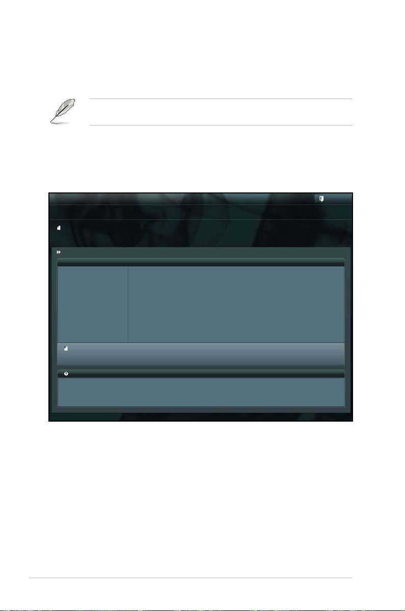
4.1.2 ASUS EZ Flash 2 Utility
The ASUS EZ Flash 2 Utility feature allows you to update the BIOS without having
to use a DOS-based utility.
Before you start using this utility, download the latest BIOS from the ASUS
website at www.asus.com.
To update the BIOS using EZ Flash 2 Utility
1. Insert the USB ash disk that contains the latest BIOS le to the USB port.
2. Enter the BIOS setup program. Go to the
Flash 2 Utility
ASUSTek EZ Flash 2 Utility V01.04
Flash Info
MODEL: Z9PH-D16 VER: 0208 DATE: 10/18/2011
fs0:\
Drive Folder Info
fs0:\ 12/09/10 10:23p 4194304 Z9PH-D16.ROM
fs1:\
File Infor
MODEL: VER: DATE:
Help Info
and press <Enter> to enable it.
menu to select
Tool
ASUS EZ
Exit
[Enter] Select or Load [Tab] Switch [Up/Down/PageUp/PageDown/Home/End] Move [Esc] Exit [F2] Backup
3. Press <Tab> to switch to the Drive eld.
4. Press the Up/Down arrow keys to nd the USB ash disk that contains the
latest BIOS, and then press <Enter>.
5. Press <Tab> to switch to the
Folder Info eld.
6. Press the Up/Down arrow keys to nd the BIOS le, and then press <Enter>
to perform the BIOS update process. Reboot the system when the update
process is done.
4-4 Chapter 4: BIOS setup
Page 63

• This function can support devices such as a USB ash disk with FAT 32/16
format and single partition only.
• DO NOT shut down or reset the system while updating the BIOS to prevent
system boot failure!
Ensure to load the BIOS default settings to ensure system compatibility and
stability. Press <F5> and select Yes to load the BIOS default settings.
4.1.3 BUPDATER utility
The succeeding BIOS screens are for reference only. The actual BIOS screen
displays may not be the same as shown.
The BUPDATER utility allows you to update the BIOS le in DOS environment
using a bootable USB ash disk drive with the updated BIOS le.
Updating the BIOS le
To update the BIOS le using the BUPDATER utility:
1. Visit the ASUS website at www.asus.com and download the latest BIOS le
for the motherboard. Save the BIOS le to a bootable USB ash disk drive.
2. Copy the BUPDATER utility (BUPDATER.exe) from the ASUS support
website at support.asus.com to the bootable USB ash disk drive you created
earlier.
3. Boot the system in DOS mode, then at the prompt, type:
BUPDATER /i[lename].ROM
where [lename] is the latest or the original BIOS le on the bootable USB
ash disk drive, then press <Enter>.
A:\>BUPDATER /i[le name].ROM
ASUS Z9PH-D16 Series 4-5
Page 64
4. The utility veries the le, then starts updating the BIOS le.
ASUSTek BIOS Update for DOS V1.06 (09/08/04)
FLASH TYPE: MXIC 25L1605A
Current ROM
BOARD: Z9PH-D16
VER: 0203
DATE: 08/24/2011
PATH:
WARNING! Do not turn off power during ash BIOS
Note
Writing BIOS:
Update ROM
BOARD: Z9PH-D16
VER: 0206
DATE: 09/30/2011
DO NOT shut down or reset the system while updating the BIOS to prevent
system boot failure!
5. The utility returns to the DOS prompt after the BIOS update process is
completed. Reboot the system from the hard disk drive.
The BIOS update is nished! Please restart your system.
C:\>
4-6 Chapter 4: BIOS setup
Page 65

4.2 BIOS setup program
This motherboard supports a programmable rmware chip that you can update
using the provided utility described in section
.
BIOS
Use the BIOS Setup program when you are installing a motherboard, reconguring
your system, or prompted to “Run Setup.” This section explains how to congure
your system using this utility.
Even if you are not prompted to use the Setup program, you can change the
conguration of your computer in the future. For example, you can enable the
security password feature or change the power management settings. This
requires you to recongure your system using the BIOS Setup program so that the
computer can recognize these changes and record them in the CMOS RAM of the
rmware chip.
The rmware chip on the motherboard stores the Setup utility. When you start up
the computer, the system provides you with the opportunity to run this program.
Press <Del> during the Power-On Self-Test (POST) to enter the Setup utility;
otherwise, POST continues with its test routines.
If you wish to enter Setup after POST, restart the system by pressing
<Ctrl+Alt+Delete>, or by pressing the reset button on the system chassis. You can
also restart by turning the system off and then back on. Do this last option only if
the rst two failed.
The Setup program is designed to make it as easy to use as possible. Being a
menu-driven program, it lets you scroll through the various sub-menus and make
your selections from the available options using the navigation keys.
4.1 Managing and updating your
• The default BIOS settings for this motherboard apply for most conditions
to ensure optimum performance. If the system becomes unstable after
changing any BIOS settings, load the default settings to ensure system
compatibility and stability. Press <F5> and select
default settings.
• The BIOS setup screens shown in this section are for reference purposes
only, and may not exactly match what you see on your screen.
• Visit the ASUS website (www.asus.com) to download the latest BIOS le for
this motherboard.
ASUS Z9PH-D16 Series 4-7
to load the BIOS
Yes
Page 66
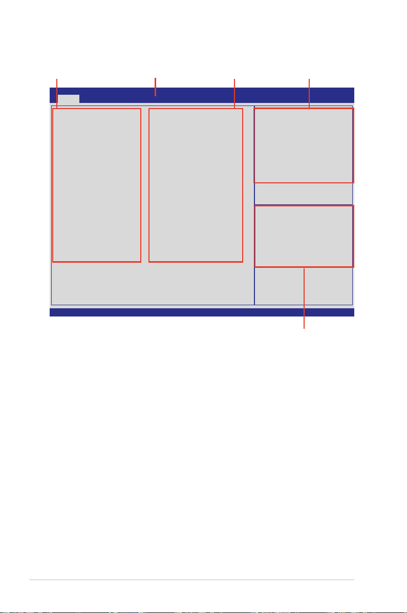
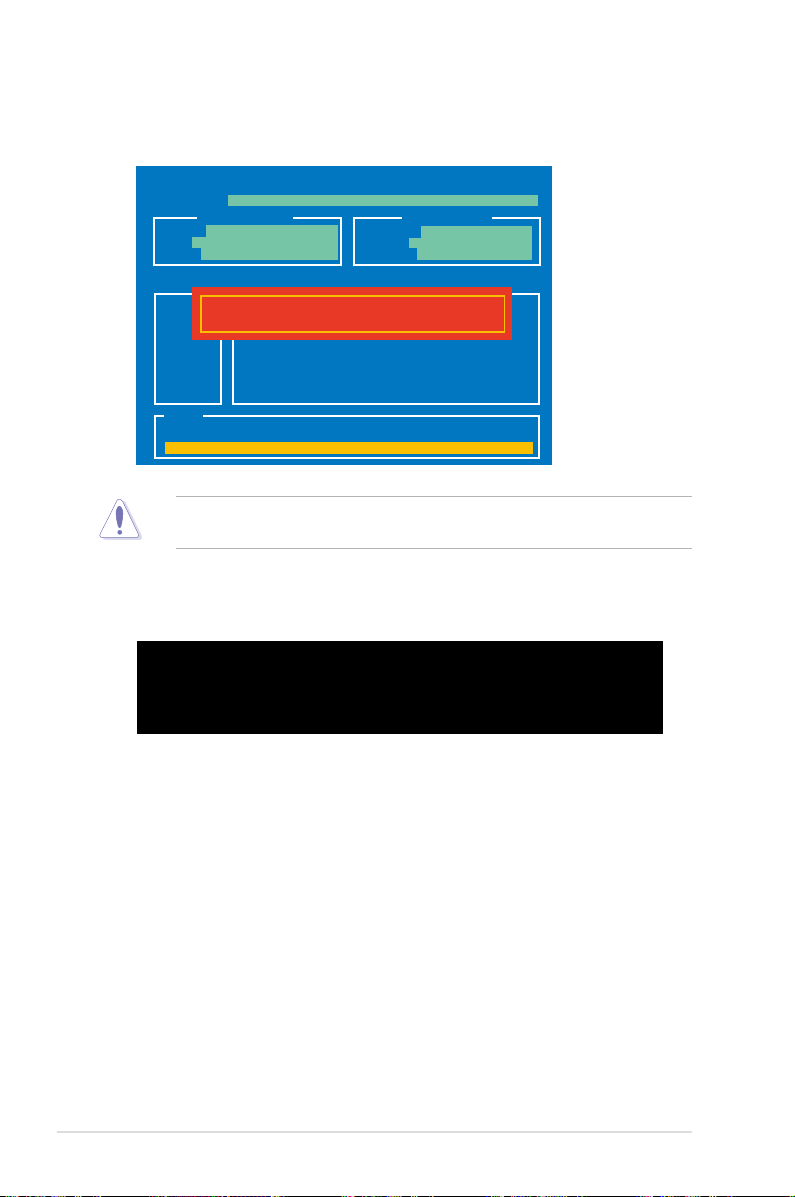
4.2.1 BIOS menu screen
Menu bar Conguration eldsMenu items
Aptio Setup Utility - Copyright (C) 2011 American Megatrends, Inc.
Main Advanced Server Mgmt Event Logs Boot Monitor Security Tool Exit
BIOS Information
BIOS Vendor American Megatrends
Core Version 4.6.4.1
Compliancy UEFI 2.1; PI 0.9
BIOS Version 0301 x64
Build Date 12/29/2011
System Date [Mon 01/02/2012]
System Time [15:07:28]
Access Level Administrator
Memory Information
Total Memory 1024 MB (DDR3)
Processor
CPU Speed 2600 MHz
Count: 1
Onboard LAN1 MAC 00:E0:18:10:14:00
Onboard LAN2 MAC 00:E0:18:10:14:01
Version 2.14.1219. Copyright (C) 2011 American Megatrends, Inc.
Set the Date, Use Tab to
switch between Data elements.
→←: Select Screen
↑↓: Select Item
Enter: Select Item
+/-: Change Opt.
F1: General Help
F2: Previous Values
F5: Optimized Defaults
F10: Save & Exit
ESC: Exit
General help
Navigation keys
4.2.2 Menu bar
The menu bar on top of the screen has the following main items:
For changing the basic system conguration
Main
Advanced
Server Mgmt
Event Logs
Monitor
Security
Boot
Tool
Exit
To select an item on the menu bar, press the right or left arrow key on the keyboard
until the desired item is highlighted.
4-8 Chapter 4: BIOS setup
For changing the advanced system settings
For changing the Server Mgmt settings
For changing the event log settings
For displaying the system temperature, power status, and
changing the fan settings
For changing the security settings
For changing the system boot conguration
For conguring options for special functions
For selecting the exit options
Page 67

4.2.3 Menu items
The highlighted item on the menu bar displays the specic items for that menu. For
example, selecting
The other items (Event Logs, Advanced, Monitor, Boot, Tool, and Exit) on the menu
bar have their respective menu items.
shows the Main menu items.
Main
4.2.4 Submenu items
A solid triangle before each item on any menu screen means that the item has a
submenu. To display the submenu, select the item and press <Enter>.
4.2.5 Navigation keys
At the bottom right corner of a menu screen are the navigation keys for the BIOS
setup program. Use the navigation keys to select items in the menu and change
the settings.
4.2.6 General help
At the top right corner of the menu screen is a brief description of the selected item.
4.2.7 Conguration elds
These elds show the values for the menu items. If an item is user-congurable,
you can change the value of the eld opposite the item. You cannot select an item
that is not user-congurable.
A congurable eld is enclosed in brackets, and is highlighted when selected. To
change the value of a eld, select it and press <Enter> to display a list of options.
4.2.8 Pop-up window
Select a menu item and press <Enter> to display a pop-up window with the
conguration options for that item.
4.2.9 Scroll bar
A scroll bar appears on the right side of a menu screen when there are items that
do not t on the screen. Press the Up/Down arrow keys or <Page Up> /<Page
Down> keys to display the other items on the screen.
ASUS Z9PH-D16 Series 4-9
Page 68

4.3 Main menu
When you enter the BIOS Setup program, the Main menu screen appears. The
Main menu provides you an overview of the basic system information, and allows
you to set the system date, time settings.
Aptio Setup Utility - Copyright (C) 2011 American Megatrends, Inc.
Main Advanced Server Mgmt Event Logs Boot Monitor Security Tool Exit
BIOS Information
BIOS Vendor American Megatrends
Core Version 4.6.4.1
Compliancy UEFI 2.1; PI 0.9
BIOS Version 0301 x64
Build Date 12/29/2011
System Date [Mon 01/02/2012]
System Time [15:07:28]
Access Level Administrator
Memory Information
Total Memory 1024 MB (DDR3)
Processor
CPU Speed 2600 MHz
Count: 1
Onboard LAN1 MAC 00:E0:18:10:14:00
Onboard LAN2 MAC 00:E0:18:10:14:01
Version 2.14.1219. Copyright (C) 2011 American Megatrends, Inc.
Set the Date, Use Tab to
switch between Data elements.
→←: Select Screen
↑↓: Select Item
Enter: Select Item
+/-: Change Opt.
F1: General Help
F2: Previous Values
F5: Optimized Defaults
F10: Save & Exit
ESC: Exit
4.3.1 System Date [Day xx/xx/xxxx]
Allows you to set the system date.
4.3.2 System Time [xx:xx:xx]
Allows you to set the system time.
4-10 Chapter 4: BIOS setup
Page 69
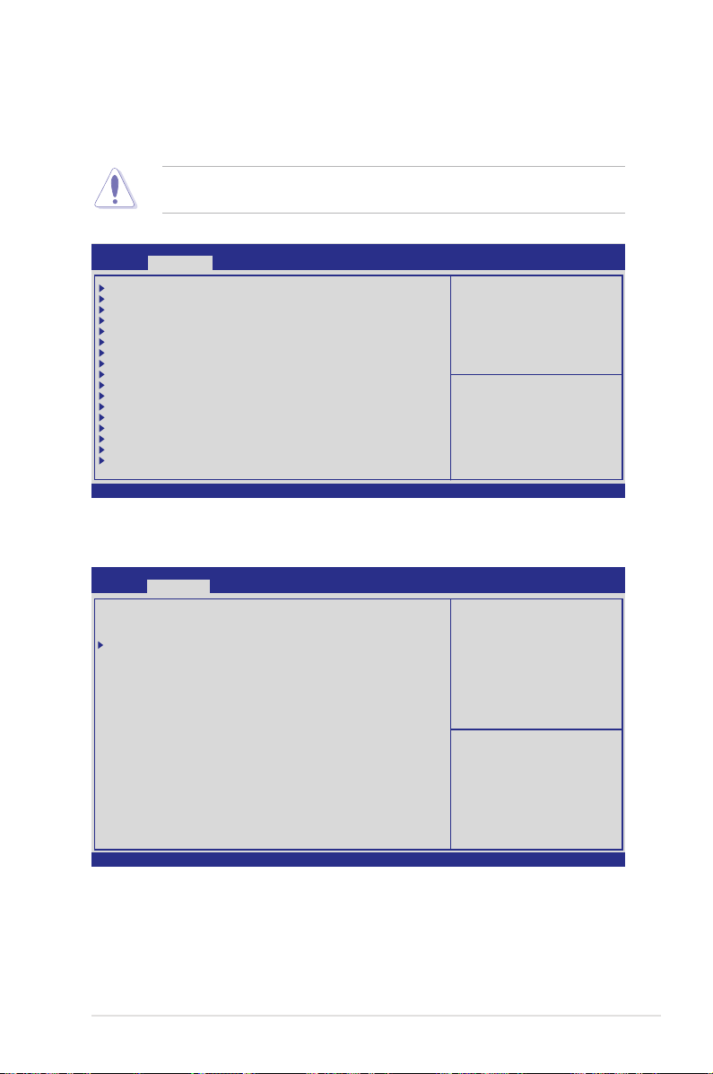
4.4 Advanced menu
The Advanced menu items allow you to change the settings for the CPU and other
system devices.
Take caution when changing the settings of the Advanced menu items. Incorrect
eld values can cause the system to malfunction.
Aptio Setup Utility - Copyright (C) 2011 American Megatrends, Inc.
Main Advanced Server Mgmt Event Logs Boot Monitor Security Tool Exit
CPU Conguration
CPU Power Management Conguration
Chipset Conguration
PCH SATA Conguration
PCH SCU Conguration
PCI Subsystem Setting
Intel TXT(LT-SX) Conguration
USB Conguration
Trusted Computing
ACPI Settings
WHEA Conguration
APM
Onboard LAN Conguration
Serial Port Console Redirection
ME Subsystem
Legacy Devices Conguration
Runtime Error Logging
Version 2.14.1219. Copyright (C) 2011 American Megatrends, Inc.
4.4.1 CPU Conguration
Aptio Setup Utility - Copyright (C) 2011 American Megatrends, Inc.
Advanced
CPU Confguration
Socket 1 CPU Information
Socket 2 Not Present
CPU Speed 2600 MHz
64-bit Supported
Hyper Threading [Enabled]
Active Processor Core [All]
Limit CPUID Maximum [Disabled]
Execute Diable Bit [Enabled]
Server Class [Custom]
Hardware Prefetcher [Enabled]
Adjacent Cache Line Prefetch [Enabled]
DCU Streamer Prefetcher [Enabled]
DCU IP Prefetcher [Enabled]
Intel Virtualization Technology [Enabled]
Local APIC Mode [Disabled]
CPU Conguration Parameters
→←: Select Screen
↑↓: Select Item
Enter: Select Item
+/-: Change Opt.
F1: General Help
F2: Previous Values
F5: Optimized Defaults
F10: Save & Exit
ESC: Exit
Socket specic CPU
Information.
→←: Select Screen
↑↓: Select Item
Enter: Select Item
+/-: Change Opt.
F1: General Help
F2: Previous Values
F5: Optimized Defaults
F10: Save & Exit
ESC: Exit
Version 2.14.1219. Copyright (C) 2011 American Megatrends, Inc.
ASUS Z9PH-D16 Series 4-11
Page 70

Socket 1 CPU Information
Enter to view socket soecic CPU Information.
Aptio Setup Utility - Copyright (C) 2011 American Megatrends, Inc.
Advanced
Socket 1 CPU Information
Genuine Intel(R) CPU @ 2.60GHz
CPU Signature 206d5
Microcode Patch 512
Max CPU Speed 2600 MHz
Min CPU Speed 1200 MHz
Processor Cores 8
Intel HT Technology Supported
Intel VT-X Technology Supported
Intel SMX Technology Supported
L1 Data Cache 32 kB x8
L1 Code Cache 32 kB x8
L2 Cache 256 kB x8
L3 Cache 20480 kB
Version 2.14.1219. Copyright (C) 2011 American Megatrends, Inc.
→←: Select Screen
↑↓: Select Item
Enter: Select Item
+/-: Change Opt.
F1: General Help
F2: Previous Values
F5: Optimized Defaults
F10: Save & Exit
ESC: Exit
Hyper Threading [Enabled]
This item allows you to enable or disable the Intel® Hyper-Threading Technology
function. When disabled, only one thread per activated core is enabled.
Conguration options: [Disabled] [Enabled]
Active Processor Cores [All]
Conguration options: [All] [1] [2] [3] [4] [5] [6] [7]
Limit CPUID Maximum [Disabled]
Setting this item to [Enabled] allows legacy operating system to boot even without
support for CPUs with extended CPUID functions.
Conguration options: [Disabled] [Enabled]
Execute Disable Bit [Enabled]
XP can prevent certain classes of malicious buffer overow attacks when combined
with a supporting OS (Windows Server 2003 SP1, Windows XP SP2, SuSE Linux
9.2, Redhat Enterprise 3 Update 3).
Conguration options: [Disabled] [Enabled]
Server Class [Custom]
Use Intel recommended prefetch settings.
Conguration options: [Enterprise] [High Performance(HPC)] [Custom]
Hardware Prefetcher [Enabled]
This Item allows you to turn on/off the mid level cache(L2) streamer prefetcher.
Conguration options: [Disabled] [Enabled]
4-12 Chapter 4: BIOS setup
Page 71

Adjacent Cache Line Prefetch [Enabled]
This Item allows you to turn on/off prefetching of adjacent cache lines.
Conguration options: [Disabled] [Enabled]
DCU Streamer Prefetcher [Enabled]
This Item allows you to enable or disable L1 data prefetcher.
Conguration options: [Disabled] [Enabled]
DCU IP Prefetcher [Enabled]
This Item allows you to enable or disable prefetch of next L1 line based upon
sequential load history.
Conguration options: [Disabled] [Enabled]
Intel Virtualization Technology [Enabled]
When enabled this item, a VMM can utilize the additional hardware capabilities
provided by Vanderpool Technology.
Conguration options: [Disabled] [Enabled]
Local APIC Mode [Disabled]
Select Local APIC mode. If Auto, use x2APIC if required. Otherwise, use xAPIC
mode. xAPIC will disable CPUs with APIC IDs greater than 254. Some OS do not
support x2APIC mode. Conguration options: [Disabled] [Enabled]
4.4.2 CPU Power Management Conguration
Aptio Setup Utility - Copyright (C) 2011 American Megatrends, Inc.
Advanced
CPU Power Management Confguration
Power Technology [Custom]
EIST [Enabled]
Turbo Mode [Enabled]
P-STATE Coordination [HW_ALL]
CPU C3 Report [Disabled]
CPU C6 Report [Enabled]
CPU C7 Report [Disabled]
Package C State limit [C6]
Energy Performance [Balanced Performance]
Factory long duration power limit 115 Watts
Long duration power limit 0
Factory long duration maintained 1000 ms
Long duration maintained 0
Recommended short duration power 1 1.2 * Long Duration
Short duration power limit 0
Version 2.14.1219. Copyright (C) 2011 American Megatrends, Inc.
This item allows you to
enabled power management
features.
→←: Select Screen
↑↓: Select Item
Enter: Select Item
+/-: Change Opt.
F1: General Help
F2: Previous Values
F5: Optimized Defaults
F10: Save & Exit
ESC: Exit
ASUS Z9PH-D16 Series 4-13
Page 72

Power Technology [Custom]
This item allows you to enable power management features.
Conguration options: [Disabled] [Energy Efcient] [Custom]
EIST [Enabled]
This item allows you to enable or disable Intel SpeedStep.
Conguration options: [Disabled] [Enabled]
Turbo Mode [Enabled]
Conguration options: [Disabled] [Enabled]
P-STATE Coordination [HW_ALL]
This item allows you to enable or disable Intel SpeedStep.
Conguration options: [HW_ALL] [SW_ALL] [SW_ANY]
CPU C3 Report [Disabled]
This item allows you to enable or disable CPU C3(ACPI C2) report.
Conguration options: [Disabled] [Enabled]
CPU C6 Report [Enabled]
This item allows you to enable or disable CPU C6(ACPI C3) report.
Conguration options: [Disabled] [Enabled]
CPU C7 Report [Disabled]
This item allows you to enable or disable CPU C7(ACPI C3) report.
Conguration options: [Disabled] [Enabled]
Package C State limit [C6]
This item allows you to set package C State limit.
Conguration options: [C0] [C2] [C6] [C7] [No Limit]
Energy Performance [Balanced Performance]
Optimize between performance and power savings. Windows 2008 and later OSes
overrides this value according to this power plan.
Conguration options: [Performance] [Balanced Performance] [Balanced Energy]
[Energy Efcient]
4-14 Chapter 4: BIOS setup
Page 73

Factory long duration power limit 115 Watts
Long duration power limit 0
Allows you to set long duration power limit in watts. Use the <+> and <-> keys to
adjust the value.
Factory long duration maintained 1000 ms
Long duration maintained 0
Allows you to set time window which the long duration power is maintained. Use
the <+> and <-> keys to adjust the value.
Recommended short duration power limitation 1.2 * Long Duration
Short duration power limit 0
Allows you to set short duration power limit in watts. Use the <+> and <-> keys to
adjust the value.
4.4.3 Chipset Conguration
Aptio Setup Utility - Copyright (C) 2011 American Megatrends, Inc.
Advanced
QPI Conguration
Memory Conguration
CPU II0 Bridge Conguration
PCH Conguration
Intel(R) VT for Directed I/O Conguration
QPI Conguration Page
QPI Conguration
Aptio Setup Utility - Copyright (C) 2011 American Megatrends, Inc.
Advanced
Current QPI Link Speed Slow
Current QPI Link Freq 8.0 GT/s
Isoc [Enabled]
QPI Link Speed Mode [Fast]
QPI Link Frequency Select [Auto]
QPI Link0s [Disabled]
QPI Link0p [Disabled]
QPI Link1 [Enabled]
Enable or disable Isoc
Isoc [Enabled]
Conguration options: [Disabled] [Enabled]
QPI Link Speed Mode [Fast]
This item allows you to select the QPI link speed as either the fast mode or slow mode.
Conguration options: [Slow] [Fast]
ASUS Z9PH-D16 Series 4-15
Page 74
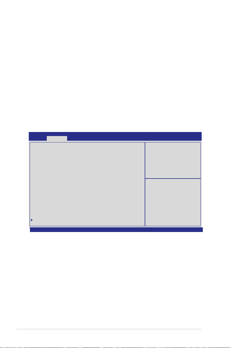
QPI Link Frequency Select [Auto]
This item allows for selecting the QPI link frequency
Conguration options: [Auto] [6.4 GT/s] [7.2 GT/s (Fast Mode Only)] [8.0 GT/s
(Fast Mode Only)]
QPI Link0s [Disabled]
Conguration options: [Disabled] [Enabled]
QPI Link0p [Disabled]
Conguration options: [Disabled] [Enabled]
QPI Link1 [Enabled]
Conguration options: [Disabled] [Enabled]
Memory Conguration
Aptio Setup Utility - Copyright (C) 2011 American Megatrends, Inc.
Advanced
Compatibility RID [Enabled]
Memory Conguration
Total Memory 1024 MB (DDR3)
Current Memory Mode Independent
Currently Memory Speed 1066 MHz
Mirroring Not Possible
Sparing Not Possible
Memory Mode [Independent]
Numa [Enabled]
DDR Speed [Auto]
Channel Interleaving [Auto]
Rank Interleaving [Auto]
Patrol Scrub [Disabled]
Demand Scrub [Enabled]
Data Scrambling [Enabled]
Device Tagging [Disabled]
Thermal Throtting [CLTT]
Enable High Temp. [Disabled]
Allow 2x Refresh [Enabled]
Altitude [300 M]
Memory HOT sensor support [Enabled]
DIMM Information
Version 2.14.1219. Copyright (C) 2011 American Megatrends, Inc.
Support for compatibility
Revision ID(CRID)
Functionality mentioned in
Sandybridge bios spec.
→←: Select Screen
↑↓: Select Item
Enter: Select Item
+/-: Change Opt.
F1: General Help
F2: Previous Values
F5: Optimized Defaults
F10: Save & Exit
ESC: Exit
Compatibility RID [Enabled]
Support for compatibility revision ID (CRID) functionality mentioned in Sandybridge
BIOS spec. Conguration options: [Enabled] [Disabled]
Memory Mode [Independent]
Select the mode for memory initializaton.
Conguration options: [Independent] [Mirroring] [Lock Step] [Sparing]
Numa [Enabled]
Enable or Disable Non uniform Memory Access (NUMA).
Conguration options: [Disabled] [Enabled]
4-16 Chapter 4: BIOS setup
Page 75

DDR Speed [Auto]
Force DDR speed. Conguration options: [Auto] [Force DDR3 800] [Force DDR3
1066] [Force DDR3 1333] [Force DDR3 1600] [Force DDR3 1866]
Channel Interleaving [Auto]
Select different channel interleaving setting.
Conguration options: [Auto] [1 Way] [2 Way] [3 Way] [4 Way]
Rank Interleaving [Auto]
Select different rank interleaving setting.
Conguration options: [Auto] [1 Way] [2 Way] [4 Way] [8 Way]
Patrol Scrub [Disabled]
Allows you to enable or disable Patrol Scrub. Conguration options: [Disabled]
[Enabled]
Demand Scrub [Enabled]
Allows you to enable or disable demand scrubing feature.
Conguration options: [Disabled] [Enabled]
Data Scrambling [Enabled]
Allows you to enable or disable data scrambling.
Conguration options: [Disabled] [Enabled]
Device Tagging [Disabled]
Allows you to enable or disable device tagging.
Conguration options: [Disabled] [Enabled]
Thermal Throtting [CLTT]
Conguration options: [Disabled] [OLTT] [CLTT]
Enable High Temp. [Disabled]
Conguration options: [Disabled] [Enabled]
Allow 2x Refresh [Enabled]
Conguration options: [Disabled] [Enabled]
Altitude [300 M]
The system altitude above the sea level in meters.
Conguration options: [Auto] [300 M] [900 M] [1500 M] [3000 M]
Memory Hot sensor support [Enabled]
Conguration options: [Disabled] [Enabled]
ASUS Z9PH-D16 Series 4-17
Page 76

DIMM Information
Aptio Setup Utility - Copyright (C) 2011 American Megatrends, Inc.
Advanced
CPU1 DIMM Information
Node 0 Ch0 Dimm A1 Present 1024 MB(DDR3)
Node 0 Ch0 Dimm A2 Not Present
Node 0 Ch1 Dimm B1 Not Present
Node 0 Ch1 Dimm B2 Not Present
Node 0 Ch2 Dimm C1 Not Present
Node 0 Ch2 Dimm C2 Not Present
Node 0 Ch3 Dimm D1 Not Present
Node 0 Ch3 Dimm D2 Not Present
CPU2 DIMM Information
CPU IIO Bridge Conguration
Aptio Setup Utility - Copyright (C) 2011 American Megatrends, Inc.
Advanced
Intel(R) I/OAT [Disabled]
DCA Support [Enabled]
VGA Priority [Offboard]
TargetVGA VGA From CPU 0
Version 2.14.1219. Copyright (C) 2011 American Megatrends, Inc.
Enables/Disables Intel(R)
I/O Acceleration Technology
(I/OAT).
→←: Select Screen
↑↓: Select Item
Enter: Select Item
+/-: Change Opt.
F1: General Help
F2: Previous Values
F5: Optimized Defaults
F10: Save & Exit
ESC: Exit
Intel(R) I/OAT [Disabled]
Allows you to enable or disable Intel I/O accelaration technology.
Conguration options: [Disabled] [Enabled]
DCA Support [Enabled]
Allows you to enable or disable direct cache access support.
Conguration options: [Disabled] [Enabled]]
VGA Priority [Offboard]
Allows you to decide priority between onboard and 1st offboard video device found.
Conguration options: [Onboard] [Offboard]
4-18 Chapter 4: BIOS setup
Page 77

PCH Conguration
Aptio Setup Utility - Copyright (C) 2011 American Megatrends, Inc.
Advanced
Name Patsburg
Stepping 04 (B0 Stepping)
SB Chipset Conguration
PCH Compatibility RID [Disabled]
Deep Sx [Disabled]
SCU devices [Enabled]
Onboard SATA RAID Oprom [Enabled]
High Precision Event Timer Conguration
High Precision Timer [Enabled]
Version 2.14.1219. Copyright (C) 2011 American Megatrends, Inc.
Support for PCH Compatibility
Revision ID(CRID)
functionality.
→←: Select Screen
↑↓: Select Item
Enter: Select Item
+/-: Change Opt.
F1: General Help
F2: Previous Values
F5: Optimized Defaults
F10: Save & Exit
ESC: Exit
PCH Compatibility RID [Disabled]
Support for PCH compatibility. Conguration options: [Disabled] [Enabled]
Deep Sx [Disabled]
Conguration options: [Disabled] [Enabled in S5] [Enabled in S4 and S5]
SCU devices [Enabled]
Allows you to enable or disable Patsburg SCU devices.
Conguration options: [Enabled] [Disabled]
Onboard SATA RAID Oprom [Enabled]
Allows you to enable or disable onboard SATA RAID option rom if Launch Storage
Oprom is enabled. Conguration options: [Disabled] [Enabled]
High Precision Event Timer Conguration
High Precision Timer [Enabled]
Allows you to enable or disable High Precision Event Timer.
Conguration options: [Disabled] [Enabled]
ASUS Z9PH-D16 Series 4-19
Page 78
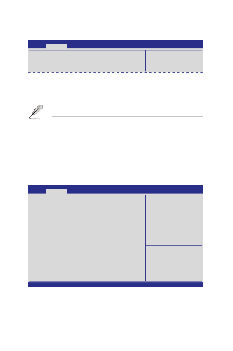
Intel(R) VT for Directed I/O Conguration
Aptio Setup Utility - Copyright (C) 2011 American Megatrends, Inc.
Advanced
Intel(R) VT-d [Disabled]
Intel(R) VT-d [Disabled]
Allows you to enable or disable Intel VT-d.
Conguration options: [Disabled] [Enabled]
Enables or Disables BIOS ACPI
Auto Conguration.
The following item appears only when you set
Intel(R) VT-d
to [Enabled].
Coherency Support [Disabled]
Allows you to enable or disable VT-d Engine Coherency support.
Conguration options: [Disabled] [Enabled]
ATS Support [Disabled]
Allows you to enable or disable VT-d Engine address translation services
(ATS) support. Conguration options: [Disabled] [Enabled]
4.4.4 PCH SATA Conguration
Aptio Setup Utility - Copyright (C) 2011 American Megatrends, Inc.
Advanced
SATA Port1 Not Present
SATA Port2 ASUS DWR ATAPI
SATA Port3 WDC WD800JD(80.0GB)
SATA Port4 Not Present
SATA Mode [AHCI Mode]
SATA Controller 1 [Enhanced]
SATA Controller 2 [Enhanced]
S.M.A.R.T. Status Check [Enabled]
Port 1 Staggered Spin-up [Disabled]
Port 2 Staggered Spin-up [Disabled]
Port 3 Staggered Spin-up [Disabled]
Port 4 Staggered Spin-up [Disabled]
Version 2.14.1219. Copyright (C) 2011 American Megatrends, Inc.
(1)IDE Mode. (2)AHCI Mode.
(3)RAID Mode.
→←: Select Screen
↑↓: Select Item
Enter: Select Item
+/-: Change Opt.
F1: General Help
F2: Previous Values
F5: Optimized Defaults
F10: Save & Exit
ESC: Exit
4-20 Chapter 4: BIOS setup
Page 79

SATA Mode [AHCI Mode]
Allows you to set the SATA conguration.
Conguration options: [Disabled] [IDE Mode] [AHCI Mode] [RAID Mode]
• If you want to use the Serial ATA hard disk drives as Parallel ATA physical
storage devices, set this item to [IDE Mode].
• If you want the Serial ATA hard disk drives to use the Advanced Host
Controller Interface (AHCI), keep the default setting[AHCI Mode]. The AHCI
allows the onboard storage driver to enable advanced Serial ATA features
that increases storage performance on random workloads by allowing the
drive to internally optimize the order of commands.
®
• If you want to create RAID sets with LSI MegaRAID utility, or Intel
Storage Technology Enterprise from the Serial ATA hard disk drives, set this
item to [RAID Mode].
Rapid
SATA Controller 1 [Enhanced]
This item appears only when you set the
SATA Mode
[Enhanced] to support two SATA 6.0 Gb/s and two SATA 3.0 Gb/s devices. Set to
[Compatible] when using Windows 98/NT/2000/MS-DOS. Up to four SATA devices
are supported under these operating systems.
Conguration options: [Disabled] [Enhanced] [Compatible]
item to [IDE Mode]. Set to
S.M.A.R.T. Status Check [Enabled]
S.M.A.R.T. (Self-Monitoring, Analysis and Reporting Technology) is a monitor
system. When read/write of your hard disk errors occur, this feature allows the hard
disk to report warning messages during the POST.
Conguration options: [Disabled] [Enabled]
Staggered Spin-up [Disabled]
Staggered spin-up is a feature dened in teh Serial ATA Specications. It enables
an HBA to individually spin-up attached SATA devices to avoid maximum current
charged by applying all attached SATA devices at the same time.
Conguration options: [Disabled] [Enabled]
ASUS Z9PH-D16 Series 4-21
Page 80

4.4.5 PCH SCU Conguration
This menu automatically detects and displays Device 1-4
Aptio Setup Utility - Copyright (C) 2011 American Megatrends, Inc.
Advanced
Device1 Not Present
Device2 Not Present
Device3 Not Present
Device4 Not Present
→←: Select Screen
↑↓: Select Item
Enter: Select Item
+/-: Change Opt.
F1: General Help
F2: Previous Values
F5: Optimized Defaults
F10: Save & Exit
ESC: Exit
4.4.6 PCI Subsystem Settings
Aptio Setup Utility - Copyright (C) 2011 American Megatrends, Inc.
Advanced
PCI Bus Driver Version V 2.05.00
PCI Option ROM Handling
PCI ROM Priority [EFI Compatible ROM]
PCI Common Setting
PCI Latency Timer [32 PCI Bus Clocks]
VGA Palette Snoop [Disabled]
PERR# Generation [Disabled]
SERR# Generation [Disabled]
Load RT32 Image [Enabled]
PCI Express Settings
PCIE Slot Option Rom Conguration
Version 2.14.1219. Copyright (C) 2011 American Megatrends, Inc.
In case of multiple Option
ROMs (Legacy and EFI
Compatible), species what
PCI option ROM to lanuch.
→←: Select Screen
↑↓: Select Item
Enter: Select Item
+/-: Change Opt.
F1: General Help
F2: Previous Values
F5: Optimized Defaults
F10: Save & Exit
ESC: Exit
4-22 Chapter 4: BIOS setup
Page 81

PCI ROM Priority [EFI Compatible ROM]
In case of multiple option roms (Legacy and EFI Compatible), species what PCI
option rom to lanuch.Conguration options: [Legacy ROM] [EFI Compatible ROM]
PCI Latency Timer [32 PCI Bus Clocks]
Value to be programmed into PCI latency timer register
Conguration options: [32 PCI Bus Clocks] [64 PCI Bus Clocks] [96 PCI Bus
Clocks] [128 PCI Bus Clocks] [160 PCI Bus Clocks] [192 PCI Bus Clocks] [224 PCI
Bus Clocks] [248 PCI Bus Clocks]
VGA Palette Snoop [Disabled]
Enables or disables VGA pallette registers snooping.
Conguration options: [Disabled] [Enabled]
PERR# Generation [Disabled]
Enables or disables PCI device to generate PERR#.
Conguration options: [Disabled] [Enabled]
Version 2.14.1219. Copyright (C) 2011 American Megatrends, Inc.
SERR# Generation [Disabled]
Enables or disables PCI device to generate SERR#.
Conguration options: [Disabled] [Enabled]
Load RT32 Image [Enabled]
Enables or disables Load RT32 Image.
Conguration options: [Disabled] [Enabled]
ASUS Z9PH-D16 Series 4-23
Page 82

PCI Express Settings
Aptio Setup Utility - Copyright (C) 2011 American Megatrends, Inc.
Advanced
PCI Express Link Register Settings
ASPM Support [Disabled]
W A RN I N G : E n a bl i n g A S P M m a y c a us e s o m e
PCI-E device to fail
Version 2.14.1219. Copyright (C) 2011 American Megatrends, Inc.
Set the ASPM Level: Force
L0s - Force all links to
L0s State: AUTO - BIOS auto
congure: DISABLE: Disables
ASPM.
→←: Select Screen
↑↓: Select Item
Enter: Select Item
+/-: Change Opt.
F1: General Help
F2: Previous Values
F5: Optimized Defaults
F10: Save & Exit
ESC: Exit
PCI Express Link Register Settings
ASPM Support [Disabled]
Allows you to set the ASPM level. Conguration options: [Disabled] [Auot] [Force
L0s]
[Force L0s] Force all links to L0s state.
[Auto] BIOS auto congure.
[Disabled] Disabled ASPM.
4-24 Chapter 4: BIOS setup
Page 83
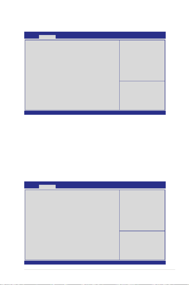
PCIE Slot Option Rom Conguration
Aptio Setup Utility - Copyright (C) 2011 American Megatrends, Inc.
Advanced
Legacy 0pROM Support
Launch Storage OpROM [Enabled]
PCIE1 Option Rom [Enabled]
Version 2.14.1219. Copyright (C) 2011 American Megatrends, Inc.
E n ab l e s o r d i sa b l e s
Boot Option for Le gacy
Mass Storage Device with
Option ROM.
→←: Select Screen
↑↓: Select Item
Enter: Select Item
+/-: Change Opt.
F1: General Help
F2: Previous Values
F5: Optimized Defaults
F10: Save & Exit
ESC: Exit
Launch Storage OpROM [Enabled]
Allows you to enable or disable Boot Option for Legacy Mass Storage Devices with
Option ROM. Conguration options: [Disabled] [Enabled]
PCIE1 Option Rom [Enabled]
Allows you to enable or disable PCIE1 Option Rom. Conguration options:
[Disabled] [Enabled]
4.4.7 Intel TXT(LT-SX) Conguration
The Intel TXT(LT-SX) conguration automatically detects and displays the Intel
TXT(LT-SX) hardware support.
Aptio Setup Utility - Copyright (C) 2011 American Megatrends, Inc.
Advanced
Intel TXT(LT-SX) Hardware Support
CPU: TXT Feature Supported
Chipset: TXT Feature Supported
Intel TXT(LT-SX) Conguration
TXT Support Disabled
Intel TXT(LT-SX) Dependencies
The following must be supported and enabled.
VT-d Support Enabled
VT Support Enabled
TPM Support Enabled
TPM State Disabled
Version 2.14.1219. Copyright (C) 2011 American Megatrends, Inc.
ASUS Z9PH-D16 Series 4-25
→←: Select Screen
↑↓: Select Item
Enter: Select Item
+/-: Change Opt.
F1: General Help
F2: Previous Values
F5: Optimized Defaults
F10: Save & Exit
ESC: Exit
Page 84

4.4.8 USB Conguration
Aptio Setup Utility - Copyright (C) 2011 American Megatrends, Inc.
Advanced
USB Conguration
USB Devices:
1Keyboard, 1 Mouse, 3 Hubs
Legacy USB Support [Enabled]
EHCI Hand-off [Disabled]
USB Hardware Delays and Time-outs
USB transfer time-out [20 sec]
Device reset time-out [20 sec]
Mass Storage Devices
USB Ports Conguration
Version 2.14.1219. Copyright (C) 2011 American Megatrends, Inc.
Legacy USB Support [Enabled]
Enables or disables Legacy USB device support. Auto option disables legacy
support if no USB devices are connected. DISABLE option will keep USB device
available only for EFI applications.
Conguration options: [Enabled] [Disabled] [Auto]
EHCI Hand-off [Disabled]
This is a workaround for 0ses without EHCI ownership change should be clained
by EHCI driver. Conguration options: [Disabled] [Enabled]
Enabled Legacy USB support.
Auto option disables legacy
support if no USB devices
are connected. DISABLE
option will keep USB devices
available only for EFI
applications.
→←: Select Screen
↑↓: Select Item
Enter: Select Item
+/-: Change Opt.
F1: General Help
F2: Previous Values
F5: Optimized Defaults
F10: Save & Exit
ESC: Exit
USB Hardware Delays and Time-outs
USB transfer time-out [20 sec]
The time-out value for control, bulk, and interrupt transfer.
Conguration options: [1 sec] [5 sec] [10 sec] [20 sec]
Device reset time-out [20 sec]
USB mass storage device start unit command time-out.
Conguration options: [10 sec] [20 sec] [30 sec] [40 sec]
4-26 Chapter 4: BIOS setup
Page 85
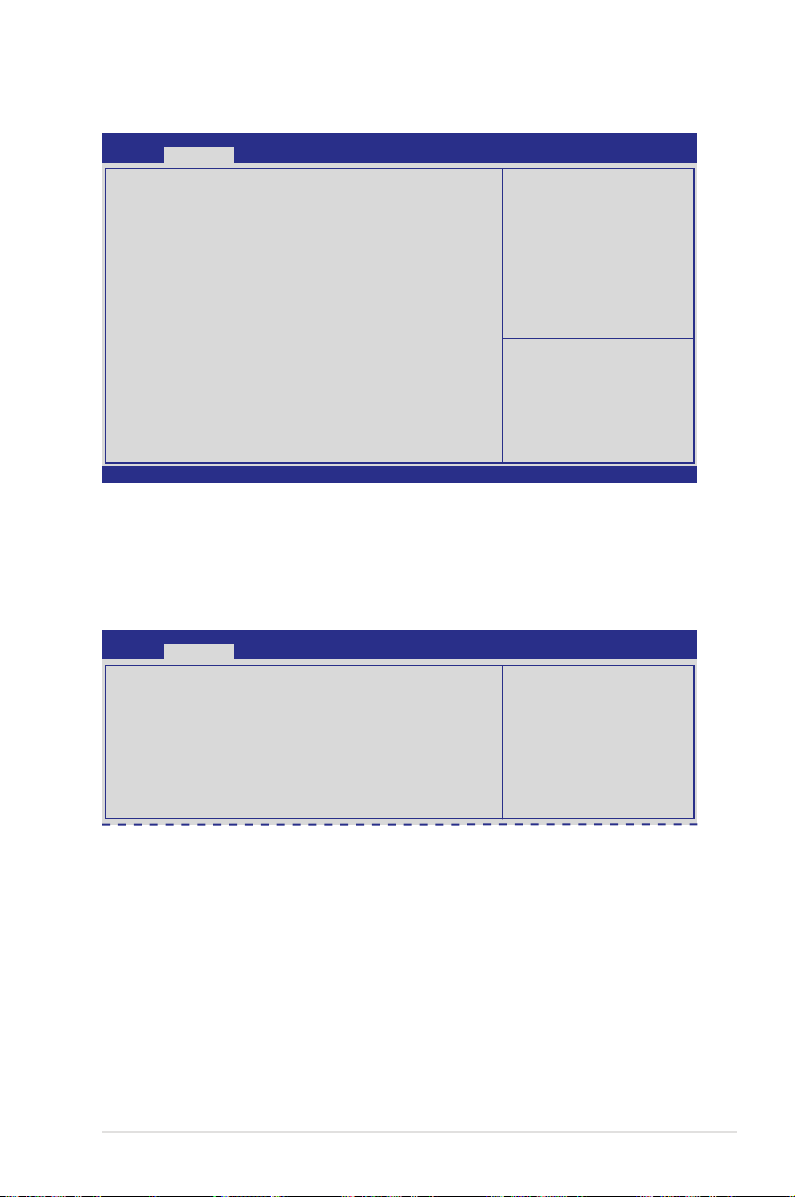
USB Ports Conguration
Aptio Setup Utility - Copyright (C) 2011 American Megatrends, Inc.
Advanced
Rear USB#1 [Enabled]
Rear USB#2 [Enabled]
Onboard USB#3 [Enabled]
Onboard USB#4 [Enabled]
Version 2.14.1219. Copyright (C) 2011 American Megatrends, Inc.
Rear / Onboard USB Port [Enabled]
Allows you to enable or disable Rear/Onboard USB port.
Conguration options: [Disabled] [Enabled]
4.4.9 Trusted Computing
Aptio Setup Utility - Copyright (C) 2011 American Megatrends, Inc.
Advanced
Conguration
TPM SUPPORT [Enabled]
Pending operation [None]
Current Status Information
TPM Enabled Status: [Disabled]
TPM Active Status: [Deactivated]
TPM Owner Status: [UnOwned]
Enable or disable USB Port 0
→←: Select Screen
↑↓: Select Item
Enter: Select Item
+/-: Change Opt.
F1: General Help
F2: Previous Values
F5: Optimized Defaults
F10: Save & Exit
ESC: Exit
Enables or Disables BIOS
support for security device.
O.S. will not show Security
Device. TCG EFI protocol and
INT1A interface will not be
available.
TPM Support [Enabled]
Allows you to enable or disable the TPM support.
Conguration options: [Disabled] [Enabled]
Pending operation [None]
Conguration options: [None] [Enable Take Owership] [Disable Take Ownership]
[TPM Clear]
ASUS Z9PH-D16 Series 4-27
Page 86

4.4.10 ACPI Settings
Aptio Setup Utility - Copyright (C) 2011 American Megatrends, Inc.
Advanced
ACPI Settings
Enable ACPI Auto Conguration [Disabled]
Enabled Hibernation [Enabled]
ACPI Sleep State [S1 (CPU Stop Clock)]
Lock Legacy Resources [Disabled]
Enable ACPI Auto Conguration [Disabled]
Allows you to enable or disable BIOS ACPI Auto Conguration.
Conguration options: [Disabled] [Enabled]
Enables or Disables BIOS ACPI
Auto Conguration.
The following item appears only when you set
Conguration
to [Disabled].
Enabled ACPI Auto
Enable Hibernation [Enabled]
Enables or disables system ability to Hibernate (0S/S4 sleep state). This option
may be not effective with some OS.
Conguration options: [Disabled] [Enabled]
ACPI Sleep State [S1 (CPU Stop Clock)]
Allows you to set the ACPI Sleep State.
Conguration options: [Suspend Disabled] [S1 (CPU Stop Clock)]
Lock Legacy Resources [Disabled]
Allows you to enable or disable Lock Legacy Resources.
Conguration options: [Disabled] [Enabled]
4-28 Chapter 4: BIOS setup
Page 87

4.4.11 WHEA Conguration
Aptio Setup Utility - Copyright (C) 2011 American Megatrends, Inc.
Advanced
WHEA Support [Enabled]
Enable or disable Windows
Hardware Error Architecture.
WHEA Support [Enabled]
Allows you to enable or disable the Windows Hardware Error Architecture support.
Conguration options: [Disabled] [Enabled]
4.4.12 APM setting
Aptio Setup Utility - Copyright (C) 2011 American Megatrends, Inc.
Advanced
Restrore AC Power Loss [Last State]
Power On By PCIE [Disabled]
Power On By Ring [Disabled]
Power On By RTC [Disabled]
Restore AC Power Loss [Last State]
When set to [Power Off], the system goes into off state after an AC power loss.
When set to [Power On], the system will reboot after an AC power loss. When set
to [Last State], the system goes into either off or on state, whatever the system
state was before the AC power loss.
Conguration options: [Power Off] [Power On] [Last State]
Specify what state to go to
when power is re-applied after
a power failure (G3 state).
Power On By PCIE [Disabled]
[Disabled] Disables the PCIE devices to generate a wake event.
[Enabled] Enables the PCIE devices to generate a wake event.
Resume On By Ring [Disabled]
When set to [Enabled], the system will generate a wake event when the external
modem receives a call while the computer is in Soft-off mode.
Conguration options: [Disabled] [Enabled]
Power On By RTC [Disabled]
[Disabled] Disables RTC to generate a wake event.
[Enabled] When set to [Eanbled], the items
Hour/Minute/Second
will become user-congurable with set
RTC Alarm Date (Days)
values.
ASUS Z9PH-D16 Series 4-29
and
Page 88

4.4.13 Onboard LAN Conguration
Aptio Setup Utility - Copyright (C) 2011 American Megatrends, Inc.
Advanced
Onboard LAN Conguration
Intel W82574L OpROM1 [PXE]
Intel W82574L OpROM2 [PXE]
Version 2.14.1219. Copyright (C) 2011 American Megatrends, Inc.
Intel W82574L OpROM1 [PXE]
Allows you to launch Intel W82574L OpROM1 boot mode.Conguration options:
[Disabled] [PXE] [iSCSI]
Intel W82574L OpROM2 [PXE]
llows you to launch Intel W82574L OpROM2 boot mode.Conguration options:
[Disabled] [PXE] [iSCSI]
Intel LAN Enable or disable.
→←: Select Screen
↑↓: Select Item
Enter: Select Item
+/-: Change Opt.
F1: General Help
F2: Previous Values
F5: Optimized Defaults
F10: Save & Exit
ESC: Exit
4-30 Chapter 4: BIOS setup
Page 89
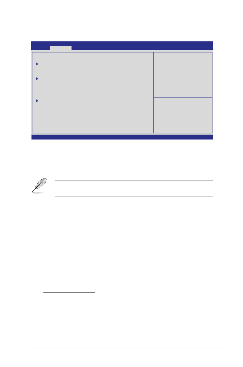
4.4.14 Serial Port Console Redirection
Aptio Setup Utility - Copyright (C) 2011 American Megatrends, Inc.
Advanced
COM1
Console Redirection [Disabled]
Console Redirection Settings
COM2 (Only for BMC)
Console Redirection [Enabled]
Console Redirection Settings
Serial Port for Out-of-Band Management/
Windows Emergency Management Services (EMS)
Console Redirection [Disabled]
Console Redirection Settings
Version 2.14.1219. Copyright (C) 2011 American Megatrends, Inc.
COM1
Console Redirection [Disabled]
Enables or disables the console redirection feature.
Conguration options: [Disabled] [Enabled]
The s ett ings s peci fy h ow
the host computer and the
remote computer (which the
user is using) will exchange
data.Both computers should
have the same or compatible
settings.
→←: Select Screen
↑↓: Select Item
Enter: Select Item
+/-: Change Opt.
F1: General Help
F2: Previous Values
F5: Optimized Defaults
F10: Save & Exit
ESC: Exit
The following item appears only when you set
Console Redirection
to
[Enabled].
Console Redirection Settings
This item becomes congurable only when you enable the
Console Redirection
item. The settings specify how the host computer and the remote computer (which
the user is using) will exchange data. Both computers should have the same or
compatible settings.
Terminal Type [VT-UTF8]
Allows you to set the terminal type.
[VT100] ASCII char set.
[VT100+] Extends VT100 to support color, function keys, et.
[VT-UTF8] Uses UTF8 encoding to map Unicode chars onto 1 or more bytes
[ANSI] Extended ASCII char set
Bits per second [57600]
Selects serial port transmission speed. The speed must be matched on the
other side. Long or noisy lines may require lower speeds.
Conguration options: [9600] [19200] [38400] [57600] [115200]
ASUS Z9PH-D16 Series 4-31
Page 90

Data Bits [8]
Conguration options: [7] [8]
Parity [None]
A parity bit can be sent with the data bits to detect some transmission errors.
[Mark] and [Space] parity do not allow for error detection.
[None] none
[Even] parity bit is 0 if the num of 1’s in the data bits is even
[Odd] parity bit is 0 if num of 1’s in the data bits is odd
[Mark] parity bit is always 1
[Space] parity bit is always 0
Stop Bits [1]
Stop bits indicate the end of a serial data packet. (A start bit indicates the
beginning.) The standard setting is 1 stop bit. Communication with slow
devices may require more than 1 stop bit. Conguration options: [1] [2]
Flow Control [Hardware RTS/CTS]
Flow control can prevent data loss from buffer overow. When sending data,
if the receiving buffers are full, a “stop” signal can be sent to stop the data
ow. Once the buffers are empty, a “start” signal can be sent to re-start the
ow. Hardware ow control uses two wires to send start/stop signals.
Conguration options: [None] [Hardware RTS/CTS]
Recorder Mode [Disabled]
With this mode enabled only text will be sent. This is to capture Terminal data.
Conguration options: [Disabled] [Enabled]
Legacy OS Redirction Resolution [80x24]
Congures the number of rows and columns supported on legacy OS.
Conguration options: [80x24] [80x25]
COM2
Console Redirection [Enabled]
Enables or disables the console redirection feature.
Conguration options: [Disabled] [Enabled]
Console Redirection Settings
Please refer to the description of the
COM1 for details.
4-32 Chapter 4: BIOS setup
Console Redirection Settings
item under
Page 91

Serial Port for Out-of-Band Management/
Windows Emergency Management Services (EMS)
Console Redirection [Disabled]
Enables or disables the console redirection feature.
Conguration options: [Disabled] [Enabled]
The following item appears only when you set
[Enabled].
Cinsloe Redirection
Console Redirection Settings
Out-of-Band Mgmt Port [COM1]
Microsoft Windows Emergency Management Services (EMS) allow for
remote management of a Windows Server OS through a serial port.
Conguration options: [COM1] [COM2 (Only for BMC)]
Terminal Type [VT-UTF8]
Microsoft Windows Emergency Management Services (EMS) allow for
remote management of a Windows Server OS through a serial port.
Conguration options: [VT100] [VT100+] [VT-UTF8] [ANSI]
Bits per second [115200]
Microsoft Windows Emergency Management Services (EMS) allow for
remote management of a Windows Server OS through a serial port.
Conguration options: [9600] [19200] [57600] [115200]
Flow Control [None]
Microsoft Windows Emergency Management Services (EMS) allow for
remote management of a Windows Server OS through a serial port.
Conguration options: [None] [Hardware RTS/CTS] [Software Xon/Xoff]
to
ASUS Z9PH-D16 Series 4-33
Page 92
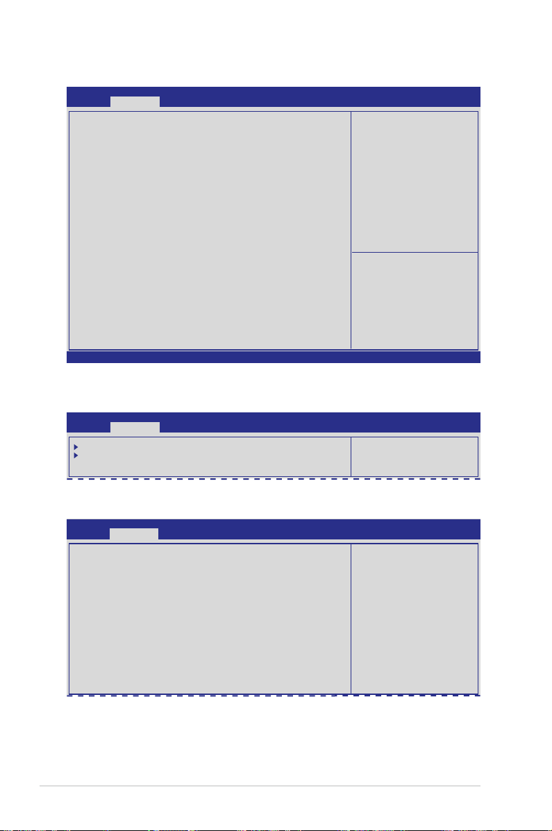
4.4.15 ME Subsystem
Aptio Setup Utility - Copyright (C) 2011 American Megatrends, Inc.
Advanced
Intel ME Subsystem Conguration
ME BIOS Interface Version 0.0
ME Version 0.0.0.0
ME FW Status Value : 0x0
ME FW State : SPS ME FW Active
ME FW Operation State: M0 without UMA
ME FW Error Code: No Error
ME Ext FW Status value: 0x0
BIOS Booting Mode: Performance ptimized
Cores Disabled: 0
ME FW SKU Information: SiEn NM
Version 2.14.1219. Copyright (C) 2011 American Megatrends, Inc.
4.4.16 Legacy Devices Conguration
Aptio Setup Utility - Copyright (C) 2011 American Megatrends, Inc.
Advanced
Serial Port 1 Conguration
Serial Port 2 Conguration
ME Subsystem Help.
→←: Select Screen
↑↓: Select Item
Enter: Select Item
+/-: Change Opt.
F1: General Help
F2: Previous Values
F5: Optimized Defaults
F10: Save & Exit
ESC: Exit
Set Parameters of serial
Port 1(COM1).
Serial Port 1/2 Conguration
Aptio Setup Utility - Copyright (C) 2011 American Megatrends, Inc.
Advanced
Serial Port Conguration
Serial Port [Enabled]
Device Settings I0=3F8h; IRQ=4
Device Mode [Standard Serial Po...]
4-34 Chapter 4: BIOS setup
Enable or Disable Serial
Port(COM).
Page 93

Serial Port [Enabled]
Allows you to enable or disable the serial port.
Conguration options: [Disabled] [Enabled]
Device Mode [Standard Serial Port Mode]
Allows you to change the serial port mode.
Conguration options: [Standard Serial Port Mode]
4.4.17 Runtime Error Logging
Aptio Setup Utility - Copyright (C) 2011 American Megatrends, Inc.
Advanced
Runtime Error Logging Support [Disabled]
Runtime Error Logging Support [Disabled]
This item allows you to enable or disable Runtime Error Logging Support.
Conguration options: [Disabled] [Enabled]
The following item appears only when you set
to [Enabled].
Runtime Error Logging Support
PCI Error Logging Support [Disabled]
Allows you to enable or disable PCI Error Logging.
Conguration options: [Disabled] [Enabled].
ASUS Z9PH-D16 Series 4-35
Page 94
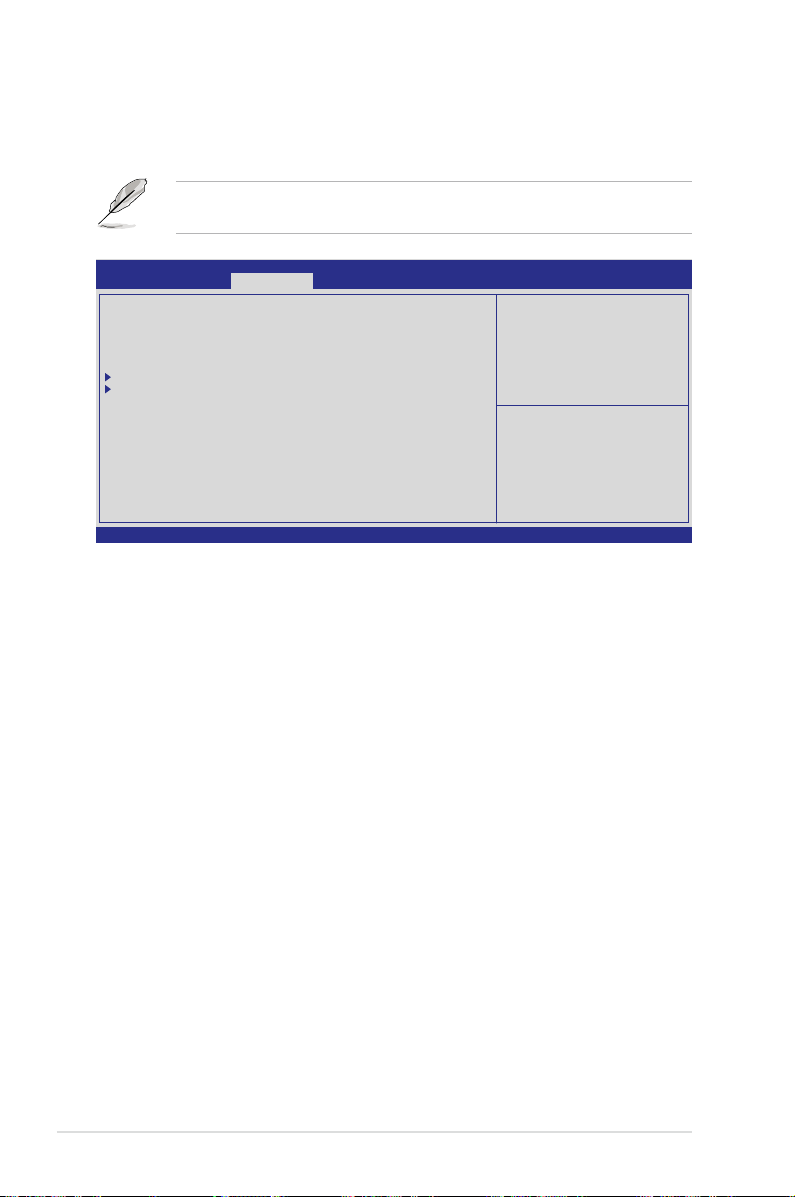
4.5 Server Mgmt menu
The Server Mgmt menu displays the server mgmt status, and allows you to change
the settings.
The Server Mgmt menu appears only when you install ASMB card on the
motherboard.
Aptio Setup Utility - Copyright (C) 2011 American Megatrends, Inc.
Main Advanced Server Mgmt Event Logs Boot Monitor Security Tool Exit
BMC Firmware: x.xx
O/S Watchdog Timer [Disabled]
O/S Wtd Timer Timeout [10 minutes]
O/S Wtd Timer Policy [Reset]
System Event Log
BMC network conguration
Version 2.14.1219. Copyright (C) 2011 American Megatrends, Inc.
O/S Watchdog Timer [Disabled]
If enabled, starts a BIOS timer which can only be shut off by Intel Management
Software after the OS loads. Helps determine that the OS sucessfully loaded or
follows the
O/S Boot Watchdog TImer Policy
Conguration options: [Enabled] [Disabled]
.
Wait for BMC response for
specied timeout In PILOTII,
BMC starts at the same time
when BIOS starts during AC
power ON. It takes arround
30 seconds to initialize
Host to BMC interfaces.
→←: Select Screen
↑↓: Select Item
Enter: Select Item
+/-: Change Opt.
F1: General Help
F2: Previous Values
F5: Optimized Defaults
F10: Save & Exit
ESC: Exit
O/S Wtd Timer Timeout [10 minutes]
Allows you to congure the length of the O/S Boot Watchdog Timer. Not available if
O/S Boot Watchdog Timer
is disabvled.
Conguration options: [5 minutes] [10 minutes] [15 minutes] [20 minutes]
O/S Wtd Timer Policy [Reset]
Allows you to congure how the system should respond if the
expires. Not available if
Timer
O/S Boot Watchdog Timer
Conguration options: [Do Nothing] [Reset] [Power Down]
4-36 Chapter 4: BIOS setup
OS Boot Watchdog
is disabled.
Page 95
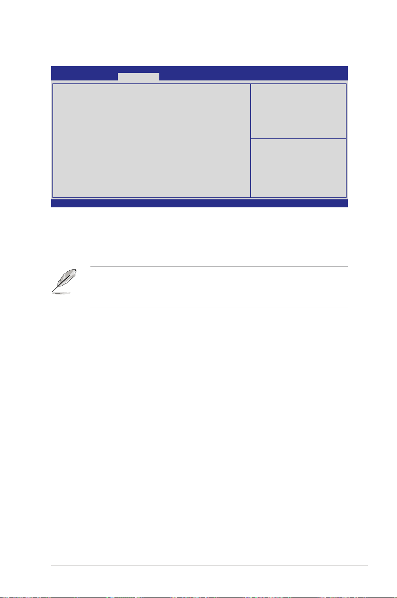
4.5.1 System Event Log
Aptio Setup Utility - Copyright (C) 2011 American Megatrends, Inc.
Server Mgmt
Enabling/Disabling Options
SEL Components [Disabled]
Erasing Settings
Erase SEL [No]
When SEL is Full [Do Nothing]
Custom EFI Logging Options
Note: All values changed here do not take effect
until computer is restarted.
Version 2.14.1219. Copyright (C) 2011 American Megatrends, Inc.
SEL Components [Disabled]
Allows you to enable or disable all features of system Event Logging during boot.
Conguration options: [Disabled] [Enabled]
Change this to enable or
disable all features of
system Event Logging during
boot.
→←: Select Screen
↑↓: Select Item
Enter: Select Item
+/-: Change Opt.
F1: General Help
F2: Previous Values
F5: Optimized Defaults
F10: Save & Exit
ESC: Exit
• The following items appears only when you set
SEL Components
[Enabled].
• All values changed here do not take effect until computer is restarted.
Erase SEL [No]
Allows you to choose options for erasing SEL.
Conguration options: [No] [Yes, On next reset] [Yes, On every reset]
When SEL is Full [Do Nothing]
Allows you to choose options for reactions to a full SEL.
Conguration options: [Do Nothing] [Erase Immediately]
Custom EFI Logging Options
to
ASUS Z9PH-D16 Series 4-37
Page 96

4.5.2 BMC network conguration
Aptio Setup Utility - Copyright (C) 2011 American Megatrends, Inc.
Server Mgmt
BMC network conguration
DM_LAN1
DM_LAN1 IP Address in BMC: 192.168.001.001
DM_LAN1 Subnet Mask in BMC: 255.255.255.000
DM_LAN1 Gateway Address in BMC : 000.000.000.000
DM_LAN1 MAC Address in BMC: 00.CE.01.87.72.A0
DM_LAN1 Address Source in BMC: Static Mode
Conguration Address source [Previous State]
Lan1
Lan1 IP Address in BMC: 192.168.001.002
Lan1 Subnet Mask in BMC: 255.255.255.000
Lan1 Gateway Address in BMC: 000.000.000.000
Lan1 MAC Address in BMC: 00.CE.01.87.72.A0
Lan1 Address Source in BMC: Static Mode
Conguration Address source [Previous State]
Version 2.14.1219. Copyright (C) 2011 American Megatrends, Inc.
Conguration Address source [Previous State]
Select to congure LAN channel parameters statically or dynamically(by BIOS
or BMC). Unspecied option will not modify any BMC network parameters during
BIOS phase.
Conguration options: [Previous State] [Static Mode] [DHCP Mode]
Select to congure LAN
channel parameters
statically or dynamically(by
BIOS or BMC). Unspecied
option will not modify any
BMC network parameters
during BIOS phase
→←: Select Screen
↑↓: Select Item
Enter: Select Item
+/-: Change Opt.
F1: General Help
F2: Previous Values
F5: Optimized Defaults
F10: Save & Exit
ESC: Exit
The following items appears only when you set
Conguration Address source
to [Static Mode].
Station IP address [0.0.0.0]
Allows you to input Station IP address.
Subnet mask [0.0.0.0]
Allows you to input Subnet mask.
Gateway IP address [0.0.0.0]
Allows you to input Gateway IP address.
4-38 Chapter 4: BIOS setup
Page 97
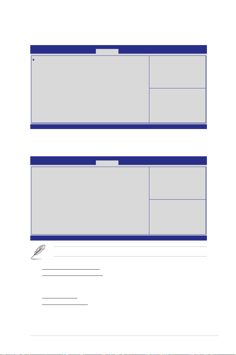
4.6 Event Logs menu
The Event Logs allows you to change or view the event log settings.
Aptio Setup Utility - Copyright (C) 2011 American Megatrends, Inc.
Main Advanced Server Mgmt Event Logs Boot Monitor Security Tool Exit
Change Smbios Event Log Settings
View Smbios Event Log
View System Event Log
Version 2.14.1219. Copyright (C) 2011 American Megatrends, Inc.
4.6.1 Change Smbios Event Log Settings
Press <Enter> to change
the Smbios Event Log
conguration.
→←: Select Screen
↑↓: Select Item
Enter: Select Item
+/-: Change Opt.
F1: General Help
F2: Previous Values
F5: Optimized Defaults
F10: Save & Exit
ESC: Exit
Press <Enter> to change the Smbios Event Log conguration.
Aptio Setup Utility - Copyright (C) 2011 American Megatrends, Inc.
Event Logs
Enabling/Disabling Options
Smbios Event Log [Enabled]
Erasing Settings
Erase Event Log [No]
When Log is Full [Do Nothing]
Smbios Event Log Standard Settings
Log System Boot Event [Disabled]
MECI 1
METW 60
Custom Option
Log OEM Codes [Enabled]
Convert OEM Codes [Disabled]
Note: All values changed here do not take effect
until computer is restarted.
Version 2.14.1219. Copyright (C) 2011 American Megatrends, Inc.
Change this to enable or
disable all features of
Smbios Event Logging during
boot.
→←: Select Screen
↑↓: Select Item
Enter: Select Item
+/-: Change Opt.
F1: General Help
F2: Previous Values
F5: Optimized Defaults
F10: Save & Exit
ESC: Exit
All values changed here do not take effect until computer is restarted.
Enabling/Disabling Options
Smbios Event Log [Enabled]
Change this to enable or disable all features of Smbios Event Logging during
boot.Conguration options: [Disabled] [Enabled]
Erasing Settings
Erase Event Log [No]
Choose options for erasing Smbios Event Log. Erasing is done prior to any
logging activation during reset.
Conguration options: [No] [Yes, Next reset] [Yes, Every reset]
ASUS Z9PH-D16 Series 4-39
Page 98

When Log is Full [Do Nothing]
Allows you to choose options for reactions to a full Smbios Event Log.
Conguration options: [Do Nothing] [Erase Immediately]
Smbios Event Log Standard Settings
Log System Boot Event [Disabled]
Allows you to choose options to enable or disable logging of System boot
event.
Conguration options: [Enabled] [Disabled]
MECI [1]
Mutiple Event Count Increment (MECI). The number of occurrences of a
duplicate event that must pass before the multiplt-event counter associated
with the log entry is updated, specied as a numeric value in the range 1 to
255.
METW [60]
Mutiple Event Time Windows (METW). The number of minutes which must
pass between duplicate log entries which utilize a multiple-event counter. The
value ranges from 0 to 99 minutes.
Custom Option
Log OEM Codes [Enabled]
Enable or disable the logging of EFI Status Codes as OEM Codes (if not
already converted to legacy).
Conguration options: [Disabled] [Enabled]
Convert OEM Codes [Disabled]
Enable or disable the converting of EFI Status Codes to Standard Smbios
Types (Not all may be translated).
Conguration options: [Disabled] [Enabled]
View Smbios Event Log
Press <Enter> to view all smbios event logs.
View System Event Log
Press <Enter> to view all system event logs.
4-40 Chapter 4: BIOS setup
Page 99

4.7 Boot menu
The Boot menu items allow you to change the system boot options.
Aptio Setup Utility - Copyright (C) 2011 American Megatrends, Inc.
Main Advanced Server Mgmt Event Logs Boot Monitor Security Tool Exit
Boot Conguration
Setup Prompt Timeout 1
Bootup NumLock State [On]
Full Screen Logo [Enabled]
CSM16 Module Version 07.67
GateA20 Active [Upon Request]
Option ROM Messages [Force BIOS]
Interrupt 19 Capture [Enabled]
Boot Device Seeking [Endless PXE]
UEFI Boot [Disabled]
Boot Option Priorities
Boot Option #1 [AMI Virtual CDROM0...]
Boot Option #2 [SATA P1: ST350041...]
Boot Option #3 [AMI Virtual Floppy...]
Boot Option #4 [IBA GE Slot 0500 v...]
CD/DVD ROM Drive BBS Priorities
Hard Drive BBS Priorities
Floppy Drive BBS Priorities
Network Device BBS Priorities
Version 2.14.1219. Copyright (C) 2011 American Megatrends, Inc.
Number of seconds to wait for
setup activation key.
65535(0xFFFF) means indenite
waiting.
→←: Select Screen
↑↓: Select Item
Enter: Select Item
+/-: Change Opt.
F1: General Help
F2: Previous Values
F5: Optimized Defaults
F10: Save & Exit
ESC: Exit
Setup Prompt Timeout [xx]
Use the <+> and <-> keys to adjust the number of seconds to wait for setup
activation key.
Bootup NumLock State [On]
Allows you to select the power-on state for the NumLock.
Conguration options: [Off] [On]
Full Screen Logo [Enabled]
Allows you to enable or disable the full screen logo display feature.
Conguration options: [Disabled] [Enabled]
Set this item to [Enabled] to use the ASUS MyLogo2™ feature.
CSM16 Module Version
GateA20 Active [Upon Request]
[Upon Request] GA20 can be disabled using BIOS services.
[Always] Do not allow disable GA20; this optionis useful when any RT code
is executed above 1MB.
Option ROM Messages [Force BIOS]
Allows you to set the display mode for Options ROM.
Conguration options: [Force BIOS] [Keep Current]
Interrupt 19 Capture [Enabled]
Allows Option ROMs to trap interrupt 19.
Conguration options: [Disabled] [Enabled]
ASUS Z9PH-D16 Series 4-41
Page 100

Boot Device Seeking [Endless PXE]
[Endless PXE] Continuous seek remote boot image until boot image found or user
abort (press Ctrl+Alt+Del).
[Normal] Seek remote boot image once then stop.
UEFI Boot [Disabled]
Enables or disables UEFI Boot.
Conguration options: [Disabled] [Enabled]
Boot Option Priorities
These items specify the boot device priority sequence from the available devices.
The number of device items that appears on the screen depends on the number of
devices installed in the system.
• To select the boot device during system startup, press <F8> when ASUS
Logo appears.
• To access Windows OS in Safe Mode, please press <F8> after POST.
Set the booting order of network devices.
Boot Option #1/#2/#3/#4 [AMI Virtual CDROM0...]
Conguration options: [SATA P1: ST3500...] [AMI Virtual CDROM...]
[AMI Virtual Floppy...] [IBA GE Slot 0500 v...]
Hard Drive BBS Priorities
CD/DVD ROM Drive BBS Priorities
Floppy Drive BBS Priorities
Network Device BBS Priorities
These items appear only when you connect SATA ODD or hard drive to the
SATA ports and allow you to set the booting order of the SATA devices.
4-42 Chapter 4: BIOS setup
 Loading...