

Asus Z9PE-D8 WS User Manual

Z9PE-D8 WS
Motherboard

E7358
Revised Edition V3
April 2012
Copyright © 2012 ASUSTeK COMPUTER INC. All Rights Reserved.
No part of this manual, including the products and software described in it, may be reproduced, transmitted,
transcribed, stored in a retrieval system, or translated into any language in any form or by any means,
except documentation kept by the purchaser for backup purposes, without the express written permission
of ASUSTeK COMPUTER INC. (“ASUS”).
Product warranty or service will not be extended if: (1) the product is repaired, modied or altered, unless
such repair, modication of alteration is authorized in writing by ASUS; or (2) the serial number of the
product is defaced or missing.
ASUS PROVIDES THIS MANUAL “AS IS” WITHOUT WARRANTY OF ANY KIND, EITHER EXPRESS
OR IMPLIED, INCLUDING BUT NOT LIMITED TO THE IMPLIED WARRANTIES OR CONDITIONS OF
MERCHANTABILITY OR FITNESS FOR A PARTICULAR PURPOSE. IN NO EVENT SHALL ASUS, ITS
DIRECTORS, OFFICERS, EMPLOYEES OR AGENTS BE LIABLE FOR ANY INDIRECT, SPECIAL,
INCIDENTAL, OR CONSEQUENTIAL DAMAGES (INCLUDING DAMAGES FOR LOSS OF PROFITS,
LOSS OF BUSINESS, LOSS OF USE OR DATA, INTERRUPTION OF BUSINESS AND THE LIKE),
EVEN IF ASUS HAS BEEN ADVISED OF THE POSSIBILITY OF SUCH DAMAGES ARISING FROM ANY
DEFECT OR ERROR IN THIS MANUAL OR PRODUCT.
SPECIFICATIONS AND INFORMATION CONTAINED IN THIS MANUAL ARE FURNISHED FOR
INFORMATIONAL USE ONLY, AND ARE SUBJECT TO CHANGE AT ANY TIME WITHOUT NOTICE, AND
SHOULD NOT BE CONSTRUED AS A COMMITMENT BY ASUS. ASUS ASSUMES NO RESPONSIBILITY
OR LIABILITY FOR ANY ERRORS OR INACCURACIES THAT MAY APPEAR IN THIS MANUAL,
INCLUDING THE PRODUCTS AND SOFTWARE DESCRIBED IN IT.
Products and corporate names appearing in this manual may or may not be registered trademarks or
copyrights of their respective companies, and are used only for identication or explanation and to the
owners’ benet, without intent to infringe.
ii

Contents
Contents ...................................................................................................... iii
Notices ....................................................................................................... viii
Federal Communications Commission Statement .......................... viii
Canadian Department of Communications Statement .................... viii
REACH ......................................................................................... viii
Safety information ...................................................................................... ix
Electrical safety ................................................................................. ix
Operation safety ................................................................................ix
About this guide .......................................................................................... x
How this guide is organized ...............................................................x
Where to nd more information ..........................................................x
Conventions used in this guide .........................................................xi
Typography .......................................................................................xi
Z9PE-D8 WS specications summary ..................................................... xii
Chapter 1: Product introduction
1.1 Welcome! ...................................................................................... 1-3
1.2 Package contents ......................................................................... 1-3
1.3 Serial number label ...................................................................... 1-4
1.4 Special features ............................................................................ 1-4
1.4.1 Product highlights ........................................................... 1-4
1.4.2 Innovative ASUS features ............................................... 1-6
Chapter 2: Hardware information
2.1 Before you proceed ..................................................................... 2-3
2.2 Motherboard overview ................................................................. 2-4
2.2.1 Placement direction ........................................................ 2-4
2.2.2 Screw holes .................................................................... 2-4
2.2.3 Motherboard layout ......................................................... 2-5
2.2.4 Layout contents ............................................................... 2-6
2.3 Central Processing Unit (CPU) ................................................... 2-8
2.3.1 Installing the CPU ........................................................... 2-8
2.4 System memory ......................................................................... 2-13
2.4.1 Overview ....................................................................... 2-13
2.4.2 Memory Congurations ................................................. 2-13
2.5 Expansion slots .......................................................................... 2-16
iii

Contents
2.5.1 Installing an expansion card ......................................... 2-16
2.5.2 Conguring an expansion card ..................................... 2-16
2.5.3 Interrupt assignments ................................................... 2-17
2.5.4 PCI Express x16 slot (x16 link) ..................................... 2-18
2.5.5 PCI Express x16 slot (x8 link) ....................................... 2-18
2.5.6 Installing the ASMB6 management board ..................... 2-19
2.6 Onboard Switches ...................................................................... 2-20
2.7 Onboard LEDs ............................................................................ 2-21
2.8 Jumpers ...................................................................................... 2-26
2.9 Connectors ................................................................................. 2-29
2.9.1 Rear panel connectors .................................................. 2-29
2.9.2 Internal connectors ....................................................... 2-31
Chapter 3: Powering up
3.1 Starting up for the rst time ........................................................ 3-3
3.2 Powering off the computer .......................................................... 3-4
3.2.1 Using the OS shut down function .................................... 3-4
3.2.2 Using the dual function power switch .............................. 3-4
Chapter 4: BIOS setup
4.1 Managing and updating your BIOS ............................................ 4-3
4.1.1 ASUS CrashFree BIOS 3 ................................................ 4-3
4.1.2 ASUS EZ Flash 2 ........................................................... 4-4
4.1.3 BUPDATER .................................................................... 4-5
4.2 BIOS setup program .................................................................... 4-7
4.2.1 BIOS menu screen .......................................................... 4-8
4.2.2 Menu bar ......................................................................... 4-8
4.2.3 Menu items ..................................................................... 4-9
4.2.4 Submenu items ............................................................... 4-9
4.2.5 Navigation keys ............................................................... 4-9
4.2.6 General help ................................................................... 4-9
4.2.7 Conguration elds ......................................................... 4-9
4.2.8 Pop-up window ............................................................... 4-9
4.2.9 Scroll bar ......................................................................... 4-9
4.3 Main menu .................................................................................. 4-10
4.3.1 System Date [Day xx/xx/xxxx] ....................................... 4-10
iv

Contents
4.3.2 System Time [xx:xx:xx] ................................................. 4-10
4.4 Ai Tweaker menu ........................................................................ 4-11
4.4.1 DRAM Timing Control .................................................. 4-13
4.5 Advanced menu ......................................................................... 4-15
4.5.1 CPU Conguration ........................................................ 4-15
4.5.2 CPU Power Management Conguration ....................... 4-18
4.5.3 Chipset Conguration ................................................... 4-20
4.5.4 PCH SATA Conguration .............................................. 4-26
4.5.5 PCH SCU Conguration ............................................... 4-27
4.5.6 PCI Subsystem Settings ............................................... 4-28
4.5.7 USB Conguration ........................................................ 4-31
4.5.8 ACPI Settings ................................................................ 4-33
4.5.9 WHEA Conguration ..................................................... 4-33
4.5.10 APM setting ................................................................... 4-34
4.5.11 Serial Port Console Redirection .................................... 4-35
4.5.12 Onboard LAN Conguration .......................................... 4-37
4.5.13 Marvell SATA Conguration .......................................... 4-38
4.5.14 Onboard Devices Conguration .................................... 4-39
4.5.15 Runtime Error Logging .................................................. 4-40
4.6 Server Management menu ........................................................ 4-41
4.6.1 System Event Log ......................................................... 4-42
4.6.2 BMC network conguration ........................................... 4-43
4.7 Event Logs menu ....................................................................... 4-44
4.7.1 Change Smbios Event Log Settings ............................. 4-45
4.8 Boot menu .................................................................................. 4-47
4.9 Monitor menu ............................................................................. 4-50
4.10 Security menu ............................................................................ 4-52
4.11 Tool menu ................................................................................... 4-53
4.12 Exit menu .................................................................................... 4-54
Chapter 5: RAID conguration
5.1 Setting up RAID ............................................................................ 5-3
5.1.1 RAID denitions .............................................................. 5-3
5.1.2 Installing hard disk drives ................................................ 5-4
5.1.3 Setting the RAID item in BIOS ........................................ 5-4
5.1.4 RAID conguration utilities .............................................. 5-4
v

Contents
5.2 LSI Software RAID Conguration Utility ................................... 5-5
5.2.1 Creating a RAID set ........................................................ 5-6
5.2.2 Adding or viewing a RAID conguration ....................... 5-12
5.2.3 Initializing the virtual drives ........................................... 5-13
5.2.4 Rebuilding failed drives ................................................. 5-17
5.2.5 Checking the drives for data consistency ..................... 5-19
5.2.6 Deleting a RAID conguration ....................................... 5-22
5.2.7 Selecting the boot drive from a RAID set ...................... 5-23
5.2.8 Enabling WriteCache .................................................... 5-24
5.3 Intel® Rapid Storage Technology enterprise SCU/SATA
Option ROM Utility ..................................................................... 5-25
5.3.1 Creating a RAID set ...................................................... 5-27
5.3.2 Creating a Recovery set ............................................... 5-28
5.3.3 Deleting a RAID set ...................................................... 5-30
5.3.4 Resetting disks to Non-RAID ........................................ 5-31
5.3.5 Exiting the Intel® Rapid Storage Technology utility ........ 5-31
5.3.6 Rebuilding the RAID ..................................................... 5-32
5.3.7 Setting the Boot array in the BIOS Setup Utility ............ 5-34
5.4 Intel® Rapid Storage Technology enterprise Utility
(Windows) ................................................................................... 5-35
5.4.1 Creating a RAID set ...................................................... 5-36
5.4.2 Change Volume Type .................................................... 5-38
5.4.3 Delete volume ............................................................... 5-39
5.4.4 Preferences ................................................................... 5-40
5.5 Marvell RAID utility .................................................................... 5-41
5.5.1 Create a RAID Array ..................................................... 5-41
5.5.2 Delete an existing RAID Array ...................................... 5-43
Chapter 6: Driver installation
6.1 RAID driver installation ............................................................... 6-3
6.1.1 Creating a RAID driver disk ............................................ 6-3
6.1.2 Installing the RAID controller driver ................................ 6-5
6.2 Intel® Chipset Device Software installation ............................. 6-14
6.3 Intel@ Network Connections Software installation.................. 6-16
6.4 Audio driver installation ............................................................ 6-19
6.5 Intel® C600 Series Chipset SCU SATA RAID Drivers
installation .................................................................................. 6-21
vi

6.6 Marvell Magni installation ......................................................... 6-22
6.7 Intel® Rapid Storage Technology enterprise 3.0 installation . 6-23
6.8 Marvell Storage Utility installation ........................................... 6-26
6.9 Asmedia ASM104x USB 3.0 Host Controller Driver
installation .................................................................................. 6-30
6.10 Intel® WG82574L Gigabit Adapters Driver installation ............ 6-33
6.11 VGA driver installation............................................................... 6-36
6.12 Management applications and utilities installation ................ 6-39
6.12.1 Running the support DVD ............................................. 6-39
6.12.2 Drivers menu ................................................................. 6-39
6.12.3 Utilities menu ................................................................ 6-40
6.12.4 Make disk menu ............................................................ 6-40
6.12.5 Contact information ....................................................... 6-40
Chapter 7: Multiple GPU technology support
7.1 AMD® CrossFireX™ technology ................................................. 7-3
7.1.1 Requirements .................................................................. 7-3
7.1.2 Before you begin ............................................................. 7-3
7.1.3 Installing two CrossFireX™ graphics cards .................... 7-4
7.1.4 Installing the device drivers ............................................. 7-5
7.1.5 Enabling the AMD® CrossFireX™ technology ................. 7-5
7.2 NVIDIA® SLI™ technology ........................................................... 7-7
7.2.1 Requirements .................................................................. 7-7
7.2.2 Installing two SLI-ready graphics cards .......................... 7-7
7.2.3 Installing three SLI-ready graphics cards ........................ 7-8
7.2.4 Installing four SLI-ready graphics cards .......................... 7-9
7.2.5 Installing the device drivers ........................................... 7-10
7.2.6 Enabling the NVIDIA® SLI™ technology ....................... 7-10
7.3 NVIDIA® CUDA™ technology .................................................... 7-13
7.3.1 Requirements ................................................................ 7-13
7.3.2 Installing CUDA-ready graphics cards .......................... 7-13
Appendix: Reference information
A.1 Z9PE-D8 WS block diagram ........................................................A-3
ASUS contact information .......................................................................... 1
vii

Notices
Federal Communications Commission Statement
This device complies with Part 15 of the FCC Rules. Operation is subject to the
following two conditions:
• This device may not cause harmful interference, and
• This device must accept any interference received including interference that
may cause undesired operation.
This equipment has been tested and found to comply with the limits for a Class
B digital device, pursuant to Part 15 of the FCC Rules. These limits are designed
to provide reasonable protection against harmful interference in a residential
installation. This equipment generates, uses and can radiate radio frequency energy
and, if not installed and used in accordance with manufacturer’s instructions, may
cause harmful interference to radio communications. However, there is no guarantee
that interference will not occur in a particular installation. If this equipment does
cause harmful interference to radio or television reception, which can be determined
by turning the equipment off and on, the user is encouraged to try to correct the
interference by one or more of the following measures:
• Reorient or relocate the receiving antenna.
• Increase the separation between the equipment and receiver.
• Connect the equipment to an outlet on a circuit different from that to which the
receiver is connected.
• Consult the dealer or an experienced radio/TV technician for help.
The use of shielded cables for connection of the monitor to the graphics card is
required to assure compliance with FCC regulations. Changes or modications
to this unit not expressly approved by the party responsible for compliance could
void the user’s authority to operate this equipment.
Canadian Department of Communications Statement
This digital apparatus does not exceed the Class B limits for radio noise emissions
from digital apparatus set out in the Radio Interference Regulations of the
Canadian Department of Communications.
This class B digital apparatus complies with Canadian ICES-003.
REACH
Complying with the REACH (Registration, Evaluation, Authorization, and Restriction
of Chemicals) regulatory framework, we publish the chemical substances in our
products at ASUS REACH website at http://csr.asus.com/english/REACH.htm.
viii

Safety information
Electrical safety
• To prevent electrical shock hazard, disconnect the power cable from the
electrical outlet before relocating the system.
• When adding or removing devices to or from the system, ensure that the
power cables for the devices are unplugged before the signal cables are
connected. If possible, disconnect all power cables from the existing system
before you add a device.
• Before connecting or removing signal cables from the motherboard, ensure
that all power cables are unplugged.
• Seek professional assistance before using an adapter or extension cord.
These devices could interrupt the grounding circuit.
• Make sure that your power supply is set to the correct voltage in your area.
If you are not sure about the voltage of the electrical outlet you are using,
contact your local power company.
• If the power supply is broken, do not try to x it by yourself. Contact a
qualied service technician or your retailer.
Operation safety
• Before installing the motherboard and adding devices on it, carefully read all
the manuals that came with the package.
• Before using the product, make sure all cables are correctly connected and the
power cables are not damaged. If you detect any damage, contact your dealer
immediately.
• To avoid short circuits, keep paper clips, screws, and staples away from
connectors, slots, sockets and circuitry.
• Avoid dust, humidity, and temperature extremes. Do not place the product in
any area where it may become wet.
• Place the product on a stable surface.
• If you encounter technical problems with the product, contact a qualied
service technician or your retailer.
throw the motherboard in municipal waste. This product has been
DO NOT
designed to enable proper reuse of parts and recycling. This symbol of the
crossed out wheeled bin indicates that the product (electrical and electronic
equipment) should not be placed in municipal waste. Check local regulations for
disposal of electronic products.
throw the mercury-containing button cell battery in municipal waste.
DO NOT
This symbol of the crossed out wheeled bin indicates that the battery should not
be placed in municipal waste.
ix

About this guide
This user guide contains the information you need when installing and conguring
the motherboard.
How this guide is organized
This user guide contains the following parts:
• Chapter 1: Product introduction
This chapter describes the features of the motherboard and the new
technologies it supports.
• Chapter 2: Hardware information
This chapter lists the hardware setup procedures that you have to perform
when installing system components. It includes description of the switches,
jumpers, and connectors on the motherboard.
• Chapter 3: Powering up
This chapter describes the power up sequence and ways of shutting down
the system.
• Chapter 4: BIOS setup
This chapter tells how to change system settings through the BIOS Setup
menus. Detailed descriptions of the BIOS parameters are also provided.
• Chapter 5: RAID conguration
This chapter provides instructions for setting up, creating, and conguring
RAID sets using the available utilities.
• Chapter 6: Driver installation
This chapter provides instructions for installing the necessary drivers for
different system components.
• Appendix: Reference information
This appendix includes additional information that you may refer to when
conguring the motherboard.
Where to nd more information
Refer to the following sources for additional information and for product and
software updates.
1. ASUS websites
The ASUS website provides updated information on ASUS hardware and
software products. Refer to the ASUS contact information.
2. Optional documentation
Your product package may include optional documentation, such as warranty
yers, that may have been added by your dealer. These documents are not
part of the standard package.
x

Conventions used in this guide
To make sure that you perform certain tasks properly, take note of the following
symbols used throughout this manual.
DANGER/WARNING:
when trying to complete a task.
CAUTION:
when trying to complete a task.
IMPORTANT:
task.
NOTE:
task.
Information to prevent damage to the components
Instructions that you MUST follow to complete a
Tips and additional information to help you complete a
Information to prevent injury to yourself
Typography
Bold text Indicates a menu or an item to select.
Italics Used to emphasize a word or a phrase.
<Key> Keys enclosed in the less-than and greater than sign means that you must press the
enclosed key.
Example: <Enter> means that you must press
the Enter or Return key.
<Key1+Key2+Key3> If you must press two or more keys
simultaneously, the key names are linked with
a plus sign (+).
Example: <Ctrl+Alt+Del>
Command
exactly as shown, then supply the required
item or value enclosed in brackets.
Example: At the DOS prompt, type the
command line:
Means that you must type the command
format A:/S
xi

Z9PE-D8 WS specications summary
CPU
Chipset
Memory
Expansion slots
VGA Output
Multi-GPU support
Storage
LAN
Audio
Dual Intel® Socket 2011 for Xeon® processor E5-2600
product family
Supports Intel® Turbo Boost Technology 2.0
QPI 6.4/7.2/8.0 GTs
*Refer to www.asus.com for CPU support list
Intel® C602 Express Chipset
8 x DIMM, Max. 256GB DDR3 1600/1333/1066/800 MHz,
Registered Memory; Max. 64GB, DDR3 2133(O.C.)/
2000(O.C.)/1866(O.C.)/1600/1333/1066 MHz, ECC,
Non-ECC, un-buffered Memory
Quad channel memory architecture
*Refer to www.asus.com for the memory QVL (Qualied
Vendors Lists).
4 x PCIe 3.0 x16 slots (Dual@x16/x16; Quad@x8/x8/x8/
x8)
2 x PCIe 3.0 x16 slots (@x16 speed)
1 x PCIe 3.0 x16 slot (@x8 speed)
* This motherboard is ready to support PCIe 3.0 SPEC.
Functions will be available when using PCIe 3.0-compliant
devices. Please refer to www.asus.com for updated details.
ASpeed AST2300 16MB
VGA port (with bracket)
Supports VGA with max. resolution 1920 x 1200@60Hz
Supports NVIDIA® 4-Way SLI™ Technology
Supports AMD® Quad-GPU CrossFireX™ Technology
Intel® C602 Chipset:
- 2 x SATA 6Gb/s ports with RAID 0,1,5 and 10 support (for
Windows only) (AHCI)
- 4 x SATA 3Gb/s ports with RAID 0,1,5 and 10 support (for
Windows only) (AHCI)
- 4 x SATA 3Gb/s ports with RAID 0,1,5 and 10 support (for
Windows only) (SCU)
Marvell® 9230 SATA controller:
- 4 x SATA 6Gb/s ports (RAID 0, 1, 10 for Windows only)
2*Intel® 82574L Gigabit LAN controller
Realtek® ALC 898 8-channel High Denition Audio
CODEC
- Supports 192kHz/ 24bit BD Lossless Sound
- DTS Surround Sensation UltraPC II
- Supports Jack-Detection, Multi-Streaming, and Front
Panel Jack-Retasking
- Optical S/PDIF Out port at back I/O
(continues on next page)
xii

Z9PE-D8 WS specications summary
USB
ASUS Unique Features
Workstation Unique
Features
Back Panel I/O Ports
ASMedia USB 3.0 controllers
- 2 x USB 3.0/2.0 ports at mid-board for front panel support
- 2 x USB 3.0/2.0 ports at back panel
Intel®C602 Chipset
- 12 x USB 2.0/1.1 ports (6 ports at mid-board, 6 ports at
back panel)
CPU Power
- Digital 7+1 Phase Power Design
DRAM Power
- Digital 2 Phase Power Design
ASUS Exclusive Features
- ASUS SSD Caching
- Front Panel USB 3.0 Support
ASUS Quiet Thermal Solution
- ASUS Fanless Design: Heat pipe solution
ASUS Q-Design
- ASUS Q-Code
- ASUS Q-Shield
- ASUS Q-Slot
- ASUS Q-DIMM
ASUS EZ DIY
- ASUS CrashFree BIOS 3
- ASUS EZ Flash 2
- ASUS MyLogo 2
- Multi-language BIOS
- 7 PCIe x 16 slots
- Quick Gate:2 vertical USB 2.0 on board
- ASWM Enterprise
- ASMB6-iKVM Remote Management Tool
2 x USB 3.0/2.0 ports (blue)
6 x USB 2.0/1.1 ports
1 x PS/2 KB port
2 x LAN (RJ45) ports (2 x Intel® LAN)
1 x Optical S/PDIF Out port
8-channel Audio I/O
(continues on next page)
xiii

Z9PE-D8 WS specications summary
Internal I/O Connectors
BIOS Features
Manageability
Accessories
Support DVD
Form Factors
1 x USB 3.0/2.0 connector support additional 2 USB ports
(19-pin)
2 x USB 2.0/1/1 connectors support additional 4 USB ports
2 x USB 2.0/1.1 type A vertical ports
6 x SATA 6Gb/s connectors
8 x SATA 3Gb/s connectors
2 x CPU Fan connector (4-pin)
6 x Chassis Fan connectors (4-pin)
2 x IEEE1394a headers
2 x Serial Port headers
1 x RAID key header
1 x ASMB6-iKVM connector
1 x VGA connector
1 x Front panel audio connector(AAFP)
1 x AUX panel header
1 x SMBus headers
1 x S/PDIF Out header
1 x Clear CMOS header
1 x 24-pin EATX Power connector
2 x 8-pin EATX 12V Power connectors
1 x 4-pin EZ_PLUG Power connector(s)
1 x System Panel
1 x PWR button
1 x Reset button
64 Mb Flash ROM, UEFI BIOS, PnP, DMI2.0, WfM2.0,
SM BIOS 2.6, ACPI 2.0a, Multi-language BIOS, ASUS EZ
Flash 2, ASUS CrashFree BIOS 3
WfM 2.0, DMI 2.0, WOL by PME, WOR by PME, PXE
6 x Serial ATA 6Gb/s cables
8 x Serial ATA 3Gb/s cables
1 x ASUS 4-Way SLI bridge connector
1 x ASUS 3-Way SLI bridge connector
1 x ASUS SLI bridge connector
1 x 2-port USB2.0 + 1394 bracket
2 x COM port bracket
I/O Shield
User’s manual
Drivers
ASUS Utilities
ASUS Update
EEB Form Factor, 12”x 13”
*Refer to ASUS Server AVL for latest update.
**Specications are subject to change without notice.
xiv

This chapter describes the motherboard
features and the new technologies it supports.
Product
introduction
1

Chapter summary
1
1.1 Welcome! ...................................................................................... 1-3
1.2 Package contents ......................................................................... 1-3
1.3 Serial number label ...................................................................... 1-4
1.4 Special features ............................................................................ 1-4
ASUS Z9PE-D8 WS
1.1 Welcome!
Thank you for buying an ASUS® Z9PE-D8 WS motherboard!
The motherboard delivers a host of new features and latest technologies, making it
another standout in the long line of ASUS quality motherboards!
Before you start installing the motherboard, and hardware devices on it, check the
items in your package with the list below.
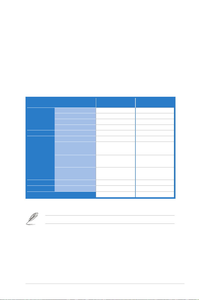
1.2 Package contents
Check your motherboard package for the following items.
Z9PE-D8 WS
SATA DOM cable
Cables
I/O Modules 2-port USB 2.0+1394a
Accessories
Application CD Support CD
Documentation User Guide
Packing Qty.
SATA 6G cable
SATA 3G cable
COM port cable
IO shield
2-Way SLI Bridge
connector
3-Way SLI Bridge
connector
4-Wat SLI Bridge
connector
If any of the above items is damaged or missing, contact your retailer.
Standard Gift Box
Pack
1 -6 -8 -2 -1 -1 1
1 --
1 --
1 --
2 2
1 1
1 or 3pcs per carton 5pcs per carton
Standard Bulk Pack
ASUS Z9PE-D8 WS 1-3

1.3 Serial number label
Before requesting support from the ASUS Technical Support team, you must take
note of the motherboard's serial number containing 12 characters
shown as the gure below. With the correct serial number of the product, ASUS
Technical Support team members can then offer a quicker and satisfying solution
to your problems.
xxS1xxxxxxxx
Z9PE-D8 WS
xxS1xxxxxxxx
Made
in
Taiwan
合格
1.4 Special features
1.4.1 Product highlights
Latest Processor Technology
The motherboard supports the latest Intel Xeon® processor E5-2600 product family
in LGA 2011 package with integrated memory controller to support 4 channel
(4DIMM per CPU) DDR3 memory. Intel Xeon® processor E5-2600 product family
supports Intel QuickPath Interconnect (QPI) with a system bus of up to 8.0GT/s.
Optimized Intel® Turbo Boost Technology
Optimized Intel® Turbo Boost Technology further optimizes the processor’s
performance and automatically allows it to run faster than the marked frequency if
it is operating below power, temperature, and current limits.
Intel® Hyper Threading
The thread-level parallelism on each processor makes more efcient use of the
processor resources, higher processing throughout, and improved performance on
today's multi-threaded software.
Intel® EM64T
The motherboard supports Intel® processors with the Intel® EM64T (Extended
Memory 64 Technology). The Intel® EM64T feature allows your computer to run on
64-bit operating systems and access larger amounts of system memory for faster
and more efcient computing.
1-4 Chapter 1: Product introduction

DDR3 memory support
The motherboard supports the 4-channel DDR3 memory that features data
transfer rates of DDR3 1600 / 1333 / 1066 MHz to boost the system’s performance,
and to meet the higher bandwidth requirements of server and workstation
applications. The 4-channel DDR3 architecture also manages trafc with bandwidth
of up to 52GB/s, and reduces voltage thus reducing power usage and heat
generation. Also, the motherboard supports LR-DIMM (Load reduced DIMM) which
uses a specially designed buffer to reduce the data load to a single load and can
increase overall server system memory capacity.
PCI Express® 3.0
PCI Express® 3.0 (PCIe 3.0) is the PCI Express bus standard that provides twice the
performance and speed of PCIe 2.0. It provides an optimal graphics performance,
unprecedented data speed, and seamless transition with its complete backward
compatibility to PCIe 1.0/2.0 devices.
Intel® 82574L Gigabit LAN Solution
This motherboard features the built-in dual server class Intel® Gigabit LAN ports,
which helps reduce CPU usage, thus increasing throughput to achieve highly-reliable
network connections, outstanding performance, and better support for diverse
operating systems.
Intel® 82574L chipset is VMware-certied to support the virtualization technology.
Enhanced Intel SpeedStep Technology (EIST)
The Enhanced Intel SpeedStep Technology (EIST) intelligently manages the
CPU resources by automatically adjusting the CPU voltage and core frequency
depending on the CPU loading and system speed or power requirement.
Serial ATA II technology
The motherboard supports the Serial ATA II 3 Gb/s technology through the Serial
ATA interface and Intel® C602 chipset. The Serial ATA II specication provides
twice the bandwidth of the current Serial ATA products with a host of new
features, including Native Command Queuing (NCQ), Power Management (PM)
Implementation Algorithm, and Hot Swap. Serial ATA allows thinner, more exible
cables with lower pin count and reduced voltage requirements.
ASUS Z9PE-D8 WS 1-5

Serial ATA III technology
The motherboard supports the Serial ATA III technology through the Serial ATA
interface and Intel® C602 chipset, delivering up to 6Gb/s data transfer rates.
Additionally, get enhanced scalability, faster data retrieval, double the bandwidth of
current bus systems.
Extra SATA 6.0 Gb/s Support
The Intel® C602 Express Chipset natively supports the next-generation Serial ATA
(SATA) interface, delivering up to 6.0 Gb/s data transfer. ASUS provides extra
SATA 6.0 Gb/s ports with enhanced scalability, faster data retrieval, and double the
bandwidth of current bus systems.
Complete USB 3.0 Integration
ASUS facilitates strategic USB 3.0 accessibility for both the front and rear panel
– 4USB 3.0 ports in total. Experience the latest plug & play connectivity at speeds
up to 10 times faster than USB 2.0. The Z9PE-D8 WS affords greater convenience
to high speed connectivity.
Temperature, fan, and voltage monitoring
The CPU temperature is monitored to prevent overheating and damage. The
system fan rotations per minute (RPM) is monitored for timely failure detection.
The chip monitors the voltage levels to ensure stable supply of current for critical
components.
1.4.2 Innovative ASUS features
ASUS Fan Speed control technology
The ASUS Fan Speed control technology smartly adjusts the fan speeds according
to the system loading to ensure quiet, cool, and efcient operation.
Best graphics performance for 4-way NVIDIA® GeForce® SLI™
Native second generation PCI-Expressx16 4-way SLI™ offers the fastest and most
reliable graphics performance ever. It's ideal for professional use in mechanical,
architectural, interior design, aeronautics, audio and video design applications.
Additionally, this ample graphics power can easily run even the most demanding
PC games in full detail for enhanced entertainment.
Quick Gate
Quick Gate is a vertical USB connector on the motherboard, allowing you to install
USB devices directly with no messy cables. This stops important data storage
devices from breaking off unexpectedly. Z9PE-D8 WS with this unique design
provides a convenient and safe way to install data and applications on your PC.
1-6 Chapter 1: Product introduction

ASUS SSD Caching
SSD caching from ASUS is easier than ever. At 3X faster, this feature boosts system
performance by using an installed SSD with no capacity limitations as a cache for
frequently accessed data. Harness a combination of SSD-like performance and
response and hard drive capacity with just one click, no rebooting needed and instant
activation for complete ease of use.
ASUS Z9PE-D8 WS 1-7

1-8 Chapter 1: Product introduction

This chapter lists the hardware setup
procedures that you have to perform
when installing system components. It
includes description of the jumpers and
connectors on the motherboard.
Chapter 2:
Hardware
2
information

Chapter summary
2
2.1 Before you proceed ..................................................................... 2-3
2.2 Motherboard overview ................................................................. 2-4
2.3 Central Processing Unit (CPU) ................................................... 2-8
2.4 System memory ......................................................................... 2-13
2.5 Expansion slots .......................................................................... 2-16
2.6 Onboard Switches ...................................................................... 2-20
2.7 Onboard LEDs ............................................................................ 2-21
2.8 Jumpers ...................................................................................... 2-26
2.9 Connectors ................................................................................. 2-29
ASUS Z9PE-D8 WS

2.1 Before you proceed
Take note of the following precautions before you install motherboard components or change
any motherboard settings.
• Unplug the power cord from the wall socket before touching any
component.
• Use a grounded wrist strap or touch a safely grounded object or a metal
object, such as the power supply case, before handling components to
avoid damaging them due to static electricity.
• Hold components by the edges to avoid touching the ICs on them.
• Whenever you uninstall any component, place it on a grounded antistatic
pad or in the bag that came with the component.
• Before you install or remove any component, ensure that the power supply
is switched off or the power cord is detached from the power supply. Failure
to do so may cause severe damage to the motherboard, peripherals, and/or
components.
ASUS Z9PE-D8 WS 2-3
2.2 Motherboard overview
Before you install the motherboard, study the conguration of your chassis to
ensure that the motherboard ts into it.
To optimize the motherboard features, we highly recommend that you install it in an
EEB compliant chassis.
Ensure to unplug the chassis power cord before installing or removing the
motherboard. Failure to do so can cause you physical injury and damage
motherboard components!
2.2.1 Placement direction
When installing the motherboard, ensure that you place it into the chassis in the
correct orientation. The edge with external ports goes to the rear part of the chassis
as indicated in the image below.
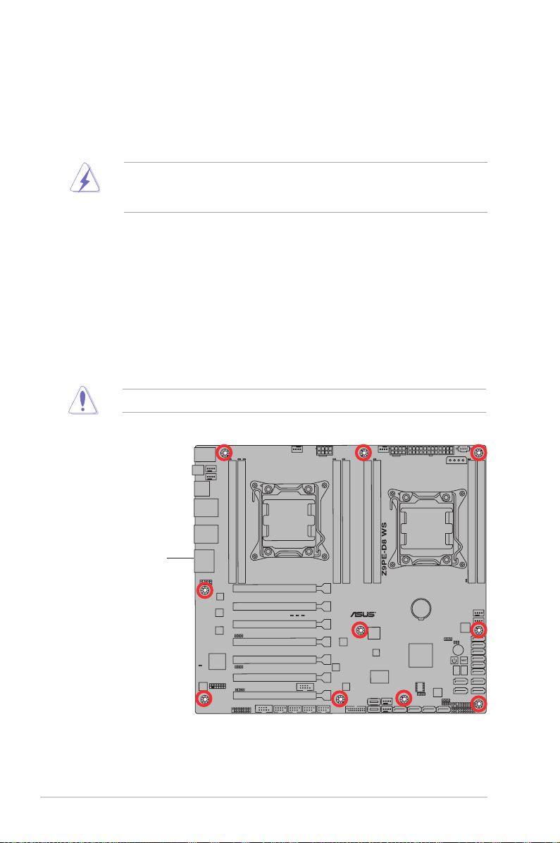
2.2.2 Screw holes
Place ten (10) screws into the holes indicated by circles to secure the motherboard
to the chassis.
DO NOT overtighten the screws! Doing so can damage the motherboard.
Place this side towards
the rear of the chassis
2-4 Chapter 2: Hardware information
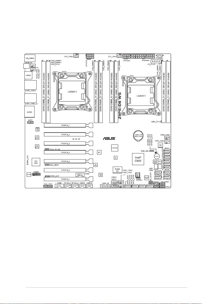
2.2.3 Motherboard layout
Z9PE-D8 WS
ASUS Z9PE-D8 WS 2-5
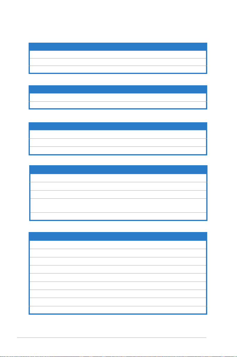
2.2.4 Layout contents
Slots/Socket Page
1. CPU sockets 2-8
2. DDR3 sockets 2-13
3. PCI Express x8 / PCI Express x16 slots 2-16
Onboard Switches Page
1. Power-on Switch
2. Reset Switch 2-20
Onboard LEDs Page
1. DIMM Error LED (ERR_DIMM)
2. Baseboard Management Controller LED (BMC_LED1)
3. Q-Code LED (LED1_LED2)
Jumpers Page
1. Clear RTC RAM (CLRTC1)
2. VGA controller setting (DIAG_VIEW1) 2-27
3. SMBUS connection setting (TESLA_M_SW) 2-27
4. LSI MegaRAID or Intel RSTe selection jumper
(3-pin RAID_SEL1)
5. ME rmware force recovery setting (3-pin ME_RCVR1) 2-28
2-20
2-21
2-21
2-22
2-26
2-28
Rear panel connectors Page
1. PS/2 mouse and keyboard port 2-29
2. LAN 2 (RJ-45) port 2-29
3. LAN 1 (RJ-45) port 2-29
4. USB 2.0 ports 5 and 6 2-29
5. Optical S/PDIF Out port 2-29
6. USB 2.0 ports 3 and 4 2-29
7. USB 2.0 ports 1 and 2 2-29
8. USB 3.0 ports 1 and 2 2-29
9. Audio I/O ports 2-29
2-6 Chapter 2: Hardware information

Internal connectors Page
1. Hard disk activity LED connector (4-pin HDLED1)
2. USB connectors (10-1 pin USB78, USB910; A-Type USB12/11)
3. USB connectors (USB3_34)
4. CPU, front and rear fan connectors (4-pin CPU_FAN1-2,
FRNT_FAN1–4, REAR_FAN1-2)
5. Power supply SMBus Connector (PSUSMB1)
6. Serial port connectors (10-1 pin COM1/COM2)
7. Serial ATA 6.0/3.0 Gb/s connectors (7-pin SATA6G_1-2 [blue];
7-pin SATA3G_3-6 [black])
8. Marvell Serial ATA 6.0 Gb/s connectors
(7-pin SATA6G_E1/E2/E3/E4 [gray])
9. Serial ATA SCU connectors (7-pin SATA_SCU1-4 [black])
10. EATX power connectors (24-pin EATXPWR1, 8-pin EATX12V1/
EATX12V2)
11. System panel connector (20-1 pin PANEL1)
12. Auxiliary panel connector (20-2 pin AUX_PANEL1)
13. Digital audio connector (4-1 pin SPDIF_OUT)
14. IEEE 1394a port connectors (10-1 pin IE1394_1/2)
15. VGA connector (VGA_HDR1)
16. Front panel audio connector (10-1 pin AAFP)
17. ASMB6 header (ASMB6)
2-31
2-31
2-32
2-32
2-33
2-33
2-34
2-35
2-36
2-36
2-37
2-38
2-39
2-39
2-40
2-40
2-41
ASUS Z9PE-D8 WS 2-7
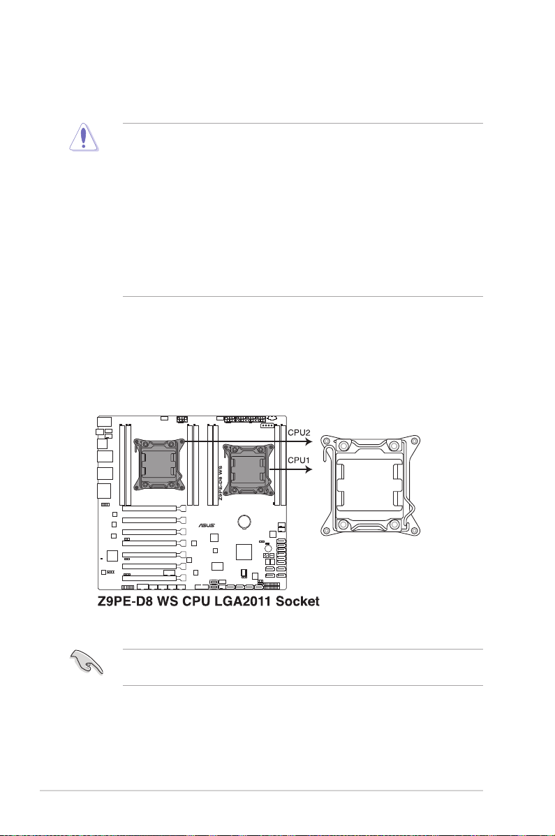
2.3 Central Processing Unit (CPU)
The motherboard comes with a surface mount LGA2011 socket designed for the
Intel® Xeon E5-2600 family processor.
• Upon purchase of the motherboard, ensure that the PnP cap is on
the socket and the socket contacts are not bent. Contact your retailer
immediately if the PnP cap is missing, or if you see any damage to the PnP
cap/socket contacts/motherboard components. ASUS will shoulder the cost
of repair only if the damage is shipment/transit-related.
• Keep the cap after installing the motherboard. ASUS will process Return
Merchandise Authorization (RMA) requests only if the motherboard comes
with the cap on the LGA2011 socket.
• The product warranty does not cover damage to the socket contacts
resulting from incorrect CPU installation/removal, or misplacement/loss/
incorrect removal of the PnP cap.
2.3.1 Installing the CPU
To install a CPU:
1. Locate the CPU socket on the motherboard.
Before installing the CPU, ensure that the socket box is facing toward you and
the load lever is on your left.
2-8 Chapter 2: Hardware information
 Loading...