

Page 1

INSTALLATION & REPLACEMENT
Installation & Replacement
Follow the procedure in this guide to perform the notebook’s
installation and replacement of various major components.
Z60Np Series Notebook combines simplicity, elegance and the most advanced
innovations in mobile computing to provide robust wired and wireless performance at
lower power levels never seen before. The key installation and replaceable items
include the HDD module, Memory module, CPU Module, Optical Drive module and
Mini-PCI module.
Be sure to follow the safety instructions described in precaution section to
safeguard the notebook against any potential damages.
This guide includes the following items:
• Appropriate Tools
• Precautions
• HDD Module Installation & Replacement
• Memory Module Installation & Replacement
►Second Memory Module
►First Memory Module
• CPU Module Installation & Replacement
• Optical Drive Module Installation & Replacement
• Mini-PCI module Installation & Replacement
1 - 1
Page 2
INSTALLATION & REPLACEMENT
TOOLS
CROSS
SCREW-
DRIVER
FLATHEAD
SCREW-
DRIVER
TWEEZERS
INSERTION
AND
EXTRACTION
TOOL FOR
FPC
CONNECTOR
VACUUM
HANDLING
TOOL
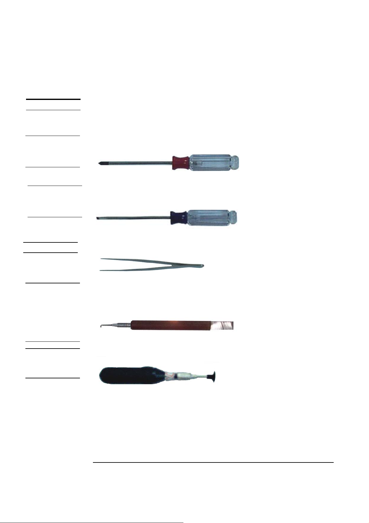
Appropriate Tools
The illustrations below show the appropriate tools that should be used for the
notebook’s service and repair.
Phillips-head Screwdriver
Use a Phillips-head screwdriver to fasten/remove the K- or B-typed screws.
Single-Slotted Screwdriver
Use a single-slotted screwdriver to lock/unlock the flexible cable connector locks
Tweezers
Use a pair of tweezers to remove/insert flexible cables.
Insertion and extraction tool for FPC connector
Use insertion and extraction tool for FPC connector to handle locking and unlocking
of FPC connectors.
Vacuum Handling Tool
1 - 2
Page 3
INSTALLATION & REPLACEMENT
Please pay special attention to the cautions below to prevent any damages to the
notebook and also please be sure to select the appropriate tools described in this
section to perform any services desired.
CAUTIONS
Precautions
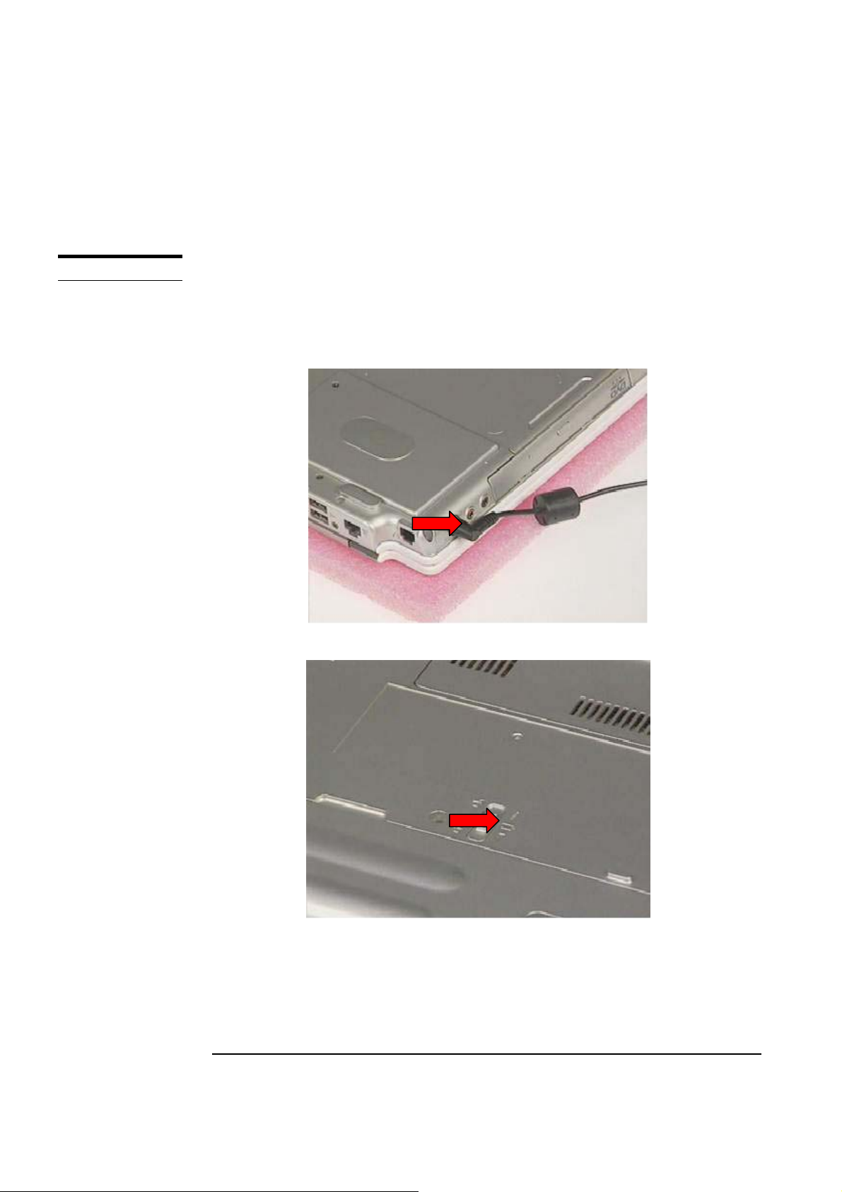
Before you perform any service and/or repair on the notebook, please follow the steps
below first.
1. Be sure that the notebook is powered down.
2. Disconnect the AC plug from the notebook
3. Turn the notebook over. Unlock and hold the latches, and remove the battery .
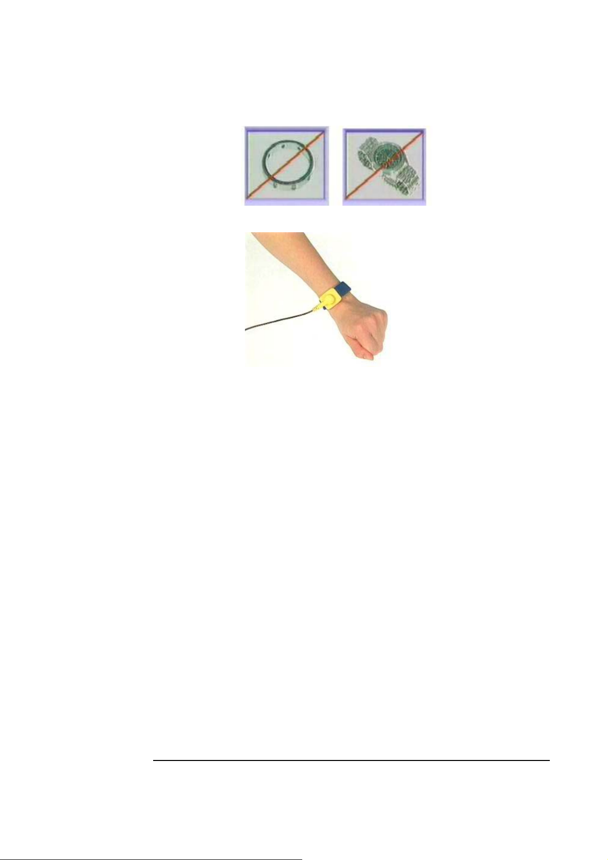
3. Remove all rings, watches and any other metal objects from your hands.
1 - 3
Page 4
INSTALLATION & REPLACEMENT
4. Always wear a ground strap on your hand to protect the notebook from static
discharge.
1 - 4
Page 5
INSTALLATION & REPLACEMENT
HDD MODULE
HDD Module
The Z60Np series Notebook uses an industry-standard 2½ HDD with IDE interface.
You can replace the HDD to any capacity of your choice within our approval and
prior test
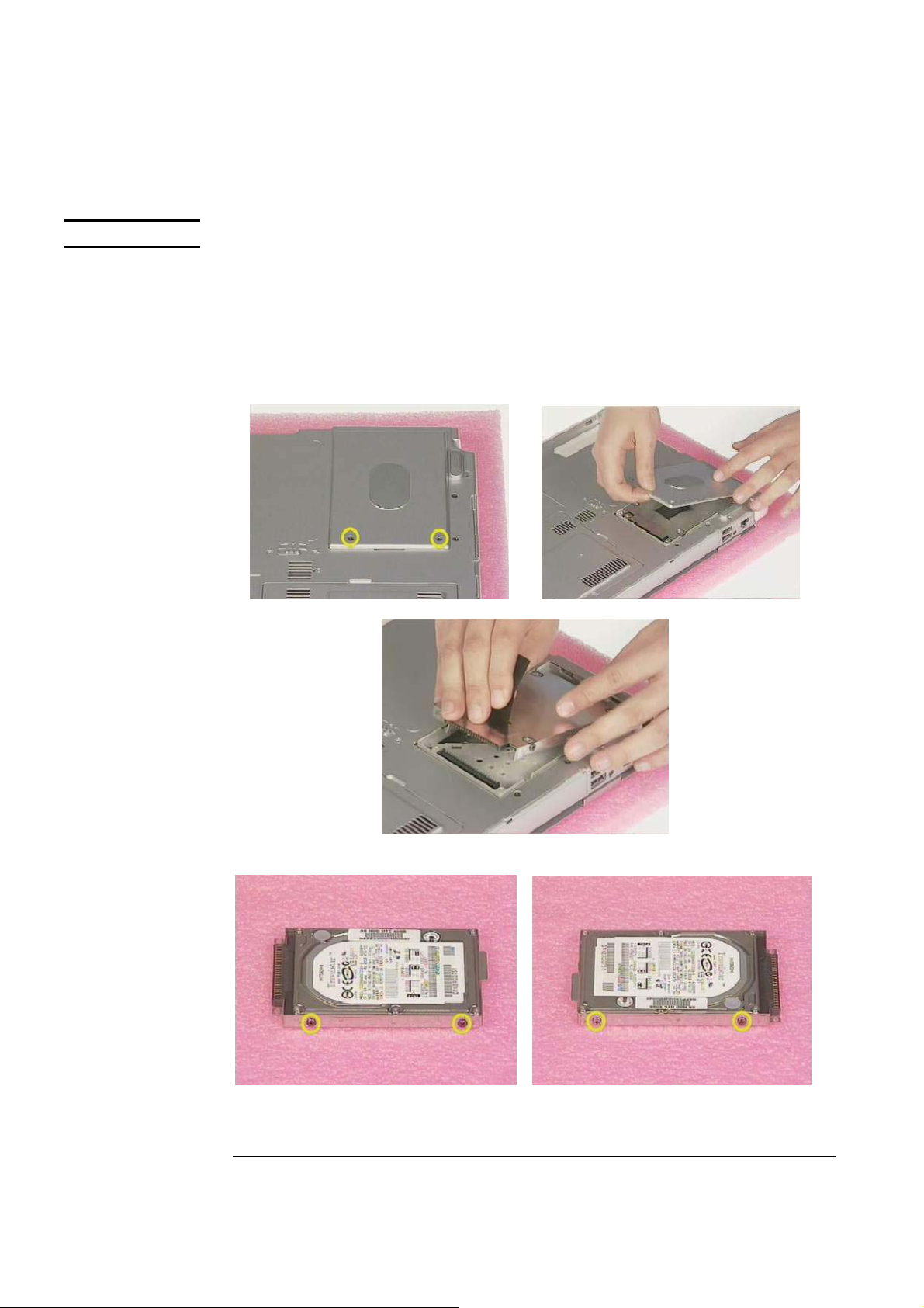
First, remove AC-power and battery.
1. Remove 2 screws(M2*4L), then remove the HDD cover and pull out the HDD
module
2. Remove 2 screw (M2*4L) on both sides
1 - 5
Page 6
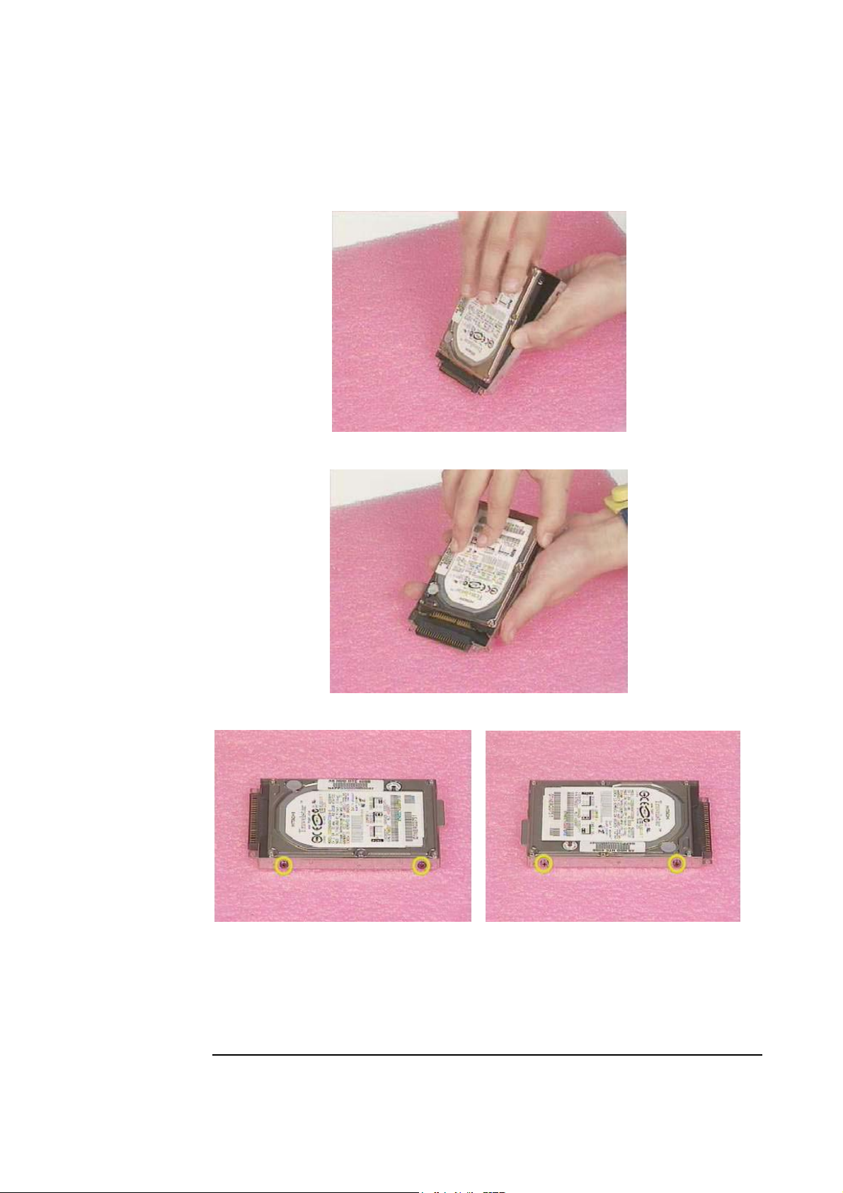
INSTALLATION & REPLACEMENT
3. Take away Hard-Disk from the HDD Housing
4. Replace the new Hard-Disk onto the HDD Housing.
5. Secure 2 screws (M2*4L) on both sides
6. Insert the HDD Moudule into the HDD Socket then place the HDD cover
and Secure 2 screws (M2*4L) to complete the Hard-Disk installation and
replacement.
1 - 6
Page 7

INSTALLATION & REPLACEMENT
MEMORY
MODULE
SECOND
MEMORY
MODULE
Memory Installation
The Z60Np Series Notebook does not have onboard RAM. There are two
SO-DIMM sockets for installing SO-DIMM RAM. It can upgrade the total
memory size up to 1GB with a 512MB module on each socket.
First, remove AC-power and battery.
Upgrading Second Memory Module
1. Remove 2 screws(M2*4L ) from CPU Cover and take the cover away
2. Remove SO-DIMM by opening the two latches to pop up it then pull the it out
3. Insert the new Memory module into the memory socket at the angle 45
degrees, push it in the socket then replace the down to latch the memory
1 - 7
Page 8

INSTALLATION & REPLACEMENT
module
FIRST
MEMORY
MODULE
4. Place the CPU Cover then Secure 2 screws (M2*4L) to fix it
Upgrading First Memory Module
1. Use the tool to prop the keyboard cover up and slide to the right and press key
“F7” then turn over the keyboard cover at the same time.
2. Remove 2 screws (M2*2.5L) of the keyboard. Then turn over the keyboard
1 - 8
Page 9

INSTALLATION & REPLACEMENT
3. Remove 2 screws (M2*4L) on the DIMM Bracketr then take it away
4. Remove SO-DIMM by opening the two latches to pop up it then pull the it out
5. Insert the new Memory module into the memory socket at the angle 45
degrees, push it in the socket then replace the down to latch the memory
module
1 - 9
Page 10

INSTALLATION & REPLACEMENT
6. Place DIMM Bracket and secure 2 screws (M2*4L) to fix it
7. Install the Keyboard module into chassis properly and secure 2 screws (M2*3L) to
fix it
8. Place the K/B COVER on top case then push the K/B COVER rightward to
lock it.
1 - 10
Page 11

INSTALLATION & REPLACEMENT
CPU MODULE
CPU
REMOVAL
CPU Module
The Z60Np Series Notebook comes standard with a Intel®’s µFC-PGA Socket on the
motherboard, which means it can support all µFC-PGA CPUs up to 1.7 GHz.
First, remove AC-power and battery.
Removing CPU
1. Remove 2 screws(M2*4L ) from CPU Cover and take the cover away
2. Remove type and remove 2 screws (M2*4L) from FAN then take the CPU Fan
over
1 - 11
Page 12

INSTALLATION & REPLACEMENT
3. Remove 4 screws (M2*4L) from Heat-Sink then take the CPU heat-sink away
4. Carefully remove the CPU thermal pad
5. Turn the non-removable screw here 180 degrees counter-clockwise to loose the
CPU
1 - 12
Page 13

INSTALLATION & REPLACEMENT
6. Don’t touch the die above the CPU. Then use the CPU vacuum hand pump to
“suck up” the CPU and take the CPU away.
CPU
INSTALLATION
Installing CPU
1. Use the CPU vacuum to “suck up” the CPU then install CPU onto the socket,
make the triangle sign on the CPU match the socket triangle sign.
2. Turn the non-removable screw here180 degrees clockwise to fix the CPU and stick
thermal pad on the CPU die
1 - 13
Page 14

INSTALLATION & REPLACEMENT
3. Place the CPU Heat-Sink on CPU then secure 4 screws (M2*4L) in sequence
and stick the warranty label
4. Place the CPU fan in the proper location then secure 2 screws (M2*4L) and
place cable properly then use tape to fix it
1 - 14
Page 15

INSTALLATION & REPLACEMENT
5. Place the CPU Cover then Secure 2 screws (M2*4L) to fix it
OPTICAL
DRIVER
REPLACEMENT
First, remove AC-power and battery.
Optical Drive Module Replacement
1. Unlock and hold it then pull the optical drive out
2. Insert the Optical Drive into the system
1 - 15
Page 16

INSTALLATION
OF MINI-PCI
MODULE
INSTALLATION & REPLACEMENT
Installing Mini-PCI module
1. Use the tool to prop the keyboard cover up and slide to the right and press key “F7”
then turn over the keyboard cover at the same time.
2. Remove 2 screws (M2*2.5L) of the keyboard. Then turn over the keyboard
3. Insert the mini-PCI module at 45 degrees angle, and then push it down to
secure.
1 - 16
Page 17

INSTALLATION & REPLACEMENT
45
1 - 17
 Loading...