

Page 1

INSTALLATION & REPLACEMENT
Installation & Replacement
Follow the individual procedures to perform the notebook’s
installation and replacement of various major components.
Z30N Series Notebook balances novelty and mobility in an elegantly designed casing.
The key installable and replaceable items include the CPU module, memory module, HDD.
Be sure to follow the safety instructions described from the start to safeguard the
notebook against any potential damages.
This chapter includes the following items:
• Appropriate Tool
• Precaution
• HDD Installation & Replacement
• Memory Installation & Replacement
CPU Installation & Replacement
•
1
Page 2
INSTALLATION & REPLACEMENT
TOOLS
CROSS
SCREW-DRIVE
R
FLATHEAD
SCREW-DRIVE
R
TWEEZERS
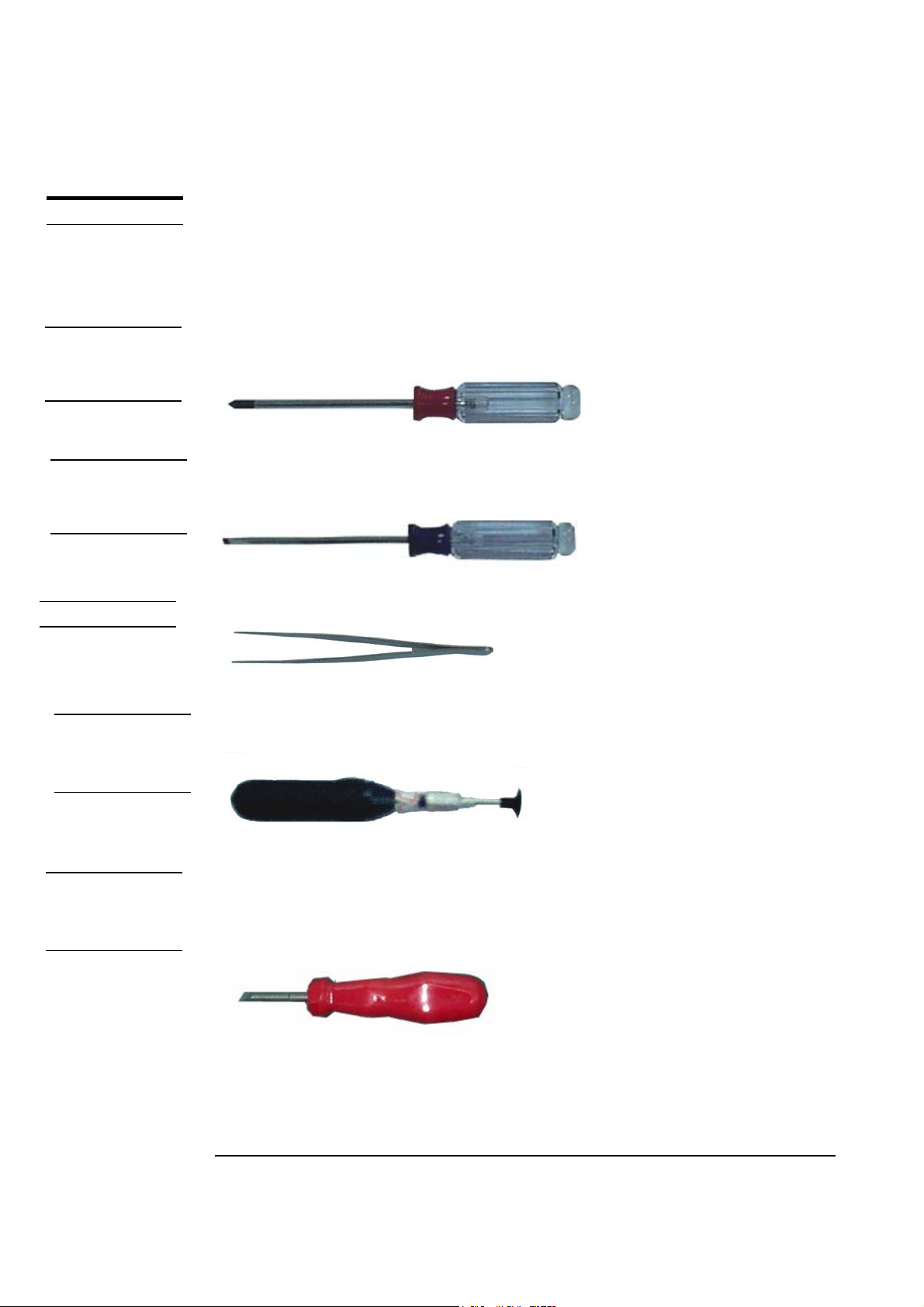
Appropriate Tools
The illustrations below show the appropriate tools that should be used for the notebook’s
service and repair.
Phillips-head Screwdriver
Use a Phillips-head screwdriver to fasten/remove the K- or B-typed screws.
Single-Slotted Screwdriver
Use a single-slotted screwdriver to lock/unlock the flexible cable connector locks
Tweezers
AMP
CPU SOCKET
TOOL
MOLEX
CPU SOCKET
TOOL
Use a pair of tweezers to remove/insert CPU warranty label.
Vacuum Handling Tool
Use vacuum handling tool to handle CPU.
Molex CPU Socket Tool
Use Molex CPU Socket tool to lock/unlock the Molex socket of CPU.
Width: 4.00mm Depth: 0.45+/-0.1mm. The angle of tip: approximate 9 degree
2
Page 3
INSTALLATION & REPLACEMENT
CAUTIONS
Precautions
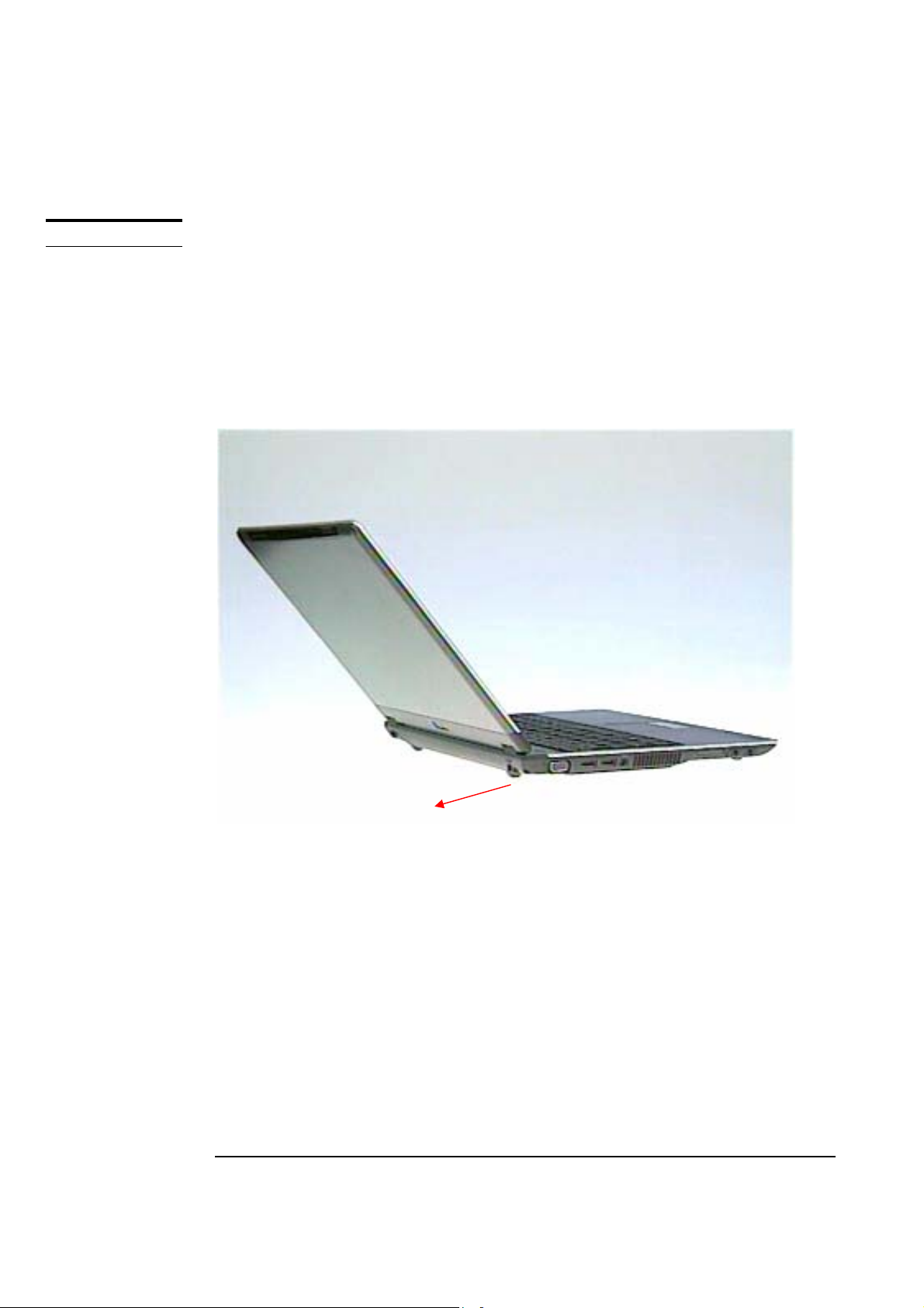
Before you perform any service and/or repair on the notebook, please follow the steps
below first.
1. Be sure that the notebook is powered down.
2. Disconnect the DC plug from the rear of the notebook (no.1 on the illustration below).
3
1
Page 4
INSTALLATION & REPLACEMENT
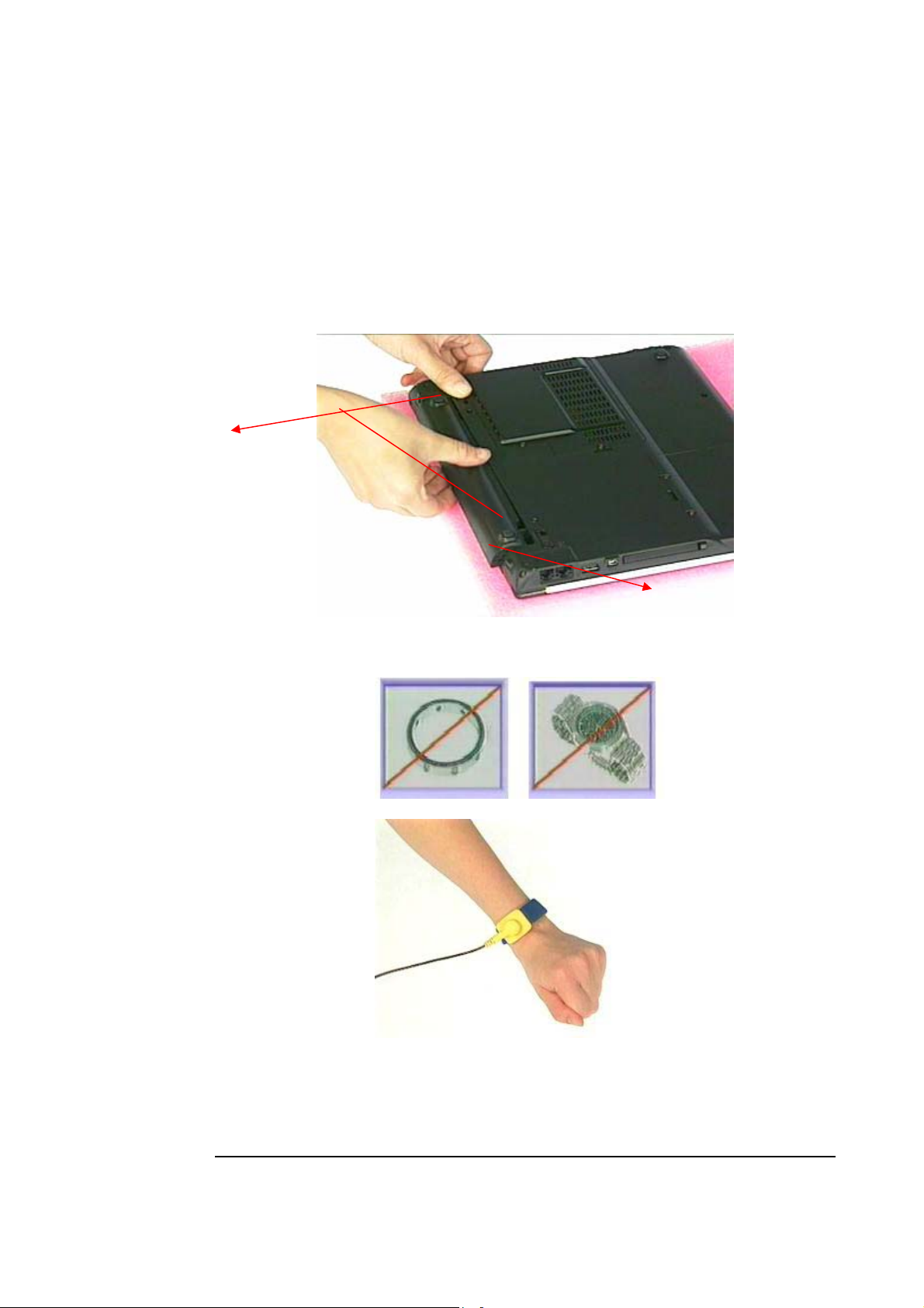
3. Turn the notebook over. Unlock and hold the latch (no.2), and remove the battery
(no.3).
2
4. Remove all rings, watches and any other metal objects from your hands.
5. Always wear a ground strap on your hand to protect the notebook from static discharge.
4
Page 5

INSTALLATION & REPLACEMENT
HDD
HDD Installation & Replacement
The Z30N Series Notebook uses an industry-standard 2½” HDD with IDE interface. You
can install the HDD to any capacity of your choice within our approval and prior test.
Installing HDD
1. Turn the notebook over and remove battery pack first.
2. Remove 2 screws on the bottom.
3. Push a new HDD into the HDD housing.
4. Hook up the HDD connector.
5
Page 6

INSTALLATION & REPLACEMENT
5. Push the HDD module into the notebook.
6. Secure 2 screws on the bottom to affix the HDD module.
6
Page 7

INSTALLATION & REPLACEMENT
Replacing HDD
1. Turn the notebook over and remove battery pack first.
2. Remove 2 screws on the bottom.
3. Pull up the HDD module a little bit and disconnect the HDD
4. Replace a new HDD into the HDD housing.
5. Push the HDD module into the notebook.
6. Secure 2 screws on the bottom to affix the HDD module.
7
Page 8

INSTALLATION & REPLACEMENT
MEMORY
Memory Installation & Replacement
The Z30N Series Notebook comes standard with 256MB of RAM onboard. There is one
expansion u-SODIMM socket for you to upgrade the total memory up to 768 MB with a
512MB module.
Installing & Replacing memory
1. Remove 2 screws from DIMM cover and remove it.
2. If there is an existing memory, remove it by opening the latches, which will pop the
module up to a 45° angles, and then pulling out the module in that angle.
Insert new memory at the same 45° angles and press down until it clicks into the
3.
latches.
8
Page 9

INSTALLATION & REPLACEMENT
4. Install DIMM cover and secure 2 screws on it.
9
Page 10

INSTALLATION & REPLACEMENT
CPU
CPU Installation & Replacement
The Z30N Series Notebook comes standard with an Intel’s µFC-PGA Socket on the
motherboard, which means it can support all µFC-PGA CPUs up to 1.7 GHz.
1. Use the CPU vacuum to “suck up” the CPU then install CPU onto the socket, make the
triangle sign on the CPU match the socket triangle sign.
2. Turn the non-removable screw here 180 degrees clockwise to fix the CPU and stick
thermal pad on the CPU die
3. Place the CPU fan in the proper location then secure 4 screws (M2*4L(K)) and
connect FAN Wire connector then place cable properly and use tape to fix it, put
a warranty label upon the screws of the fan module.
10
Page 11

INSTALLATION & REPLACEMENT
Note: If fan module has no thermal pad on it, please plus a thermal pad on
the CPU die before assembling.
11
 Loading...