


Z11PA-U12 Series
User Guide

E17479
Revised Edition V6
October 2020
Copyright © 2020 ASUSTeK COMPUTER INC. All Rights Reserved.
No part of this manual, including the products and software described in it, may be reproduced, transmitted,
transcribed, stored in a retrieval system, or translated into any language in any form or by any means,
except documentation kept by the purchaser for backup purposes, without the express written permission
of ASUSTeK COMPUTER INC. (“ASUS”).
Product warranty or service will not be extended if: (1) the product is repaired, modied or altered, unless
such repair, modication of alteration is authorized in writing by ASUS; or (2) the serial number of the
product is defaced or missing.
ASUS PROVIDES THIS MANUAL “AS IS” WITHOUT WARRANTY OF ANY KIND, EITHER EXPRESS
OR IMPLIED, INCLUDING BUT NOT LIMITED TO THE IMPLIED WARRANTIES OR CONDITIONS OF
MERCHANTABILITY OR FITNESS FOR A PARTICULAR PURPOSE. IN NO EVENT SHALL ASUS, ITS
DIRECTORS, OFFICERS, EMPLOYEES OR AGENTS BE LIABLE FOR ANY INDIRECT, SPECIAL,
INCIDENTAL, OR CONSEQUENTIAL DAMAGES (INCLUDING DAMAGES FOR LOSS OF PROFITS,
LOSS OF BUSINESS, LOSS OF USE OR DATA, INTERRUPTION OF BUSINESS AND THE LIKE),
EVEN IF ASUS HAS BEEN ADVISED OF THE POSSIBILITY OF SUCH DAMAGES ARISING FROM ANY
DEFECT OR ERROR IN THIS MANUAL OR PRODUCT.
SPECIFICATIONS AND INFORMATION CONTAINED IN THIS MANUAL ARE FURNISHED FOR
INFORMATIONAL USE ONLY, AND ARE SUBJECT TO CHANGE AT ANY TIME WITHOUT NOTICE,
AND SHOULD NOT BE CONSTRUED AS A COMMITMENT BY ASUS. ASUS ASSUMES NO
RESPONSIBILITY OR LIABILITY FOR ANY ERRORS OR INACCURACIES THAT MAY APPEAR IN THIS
MANUAL, INCLUDING THE PRODUCTS AND SOFTWARE DESCRIBED IN IT.
Products and corporate names appearing in this manual may or may not be registered trademarks or
copyrights of their respective companies, and are used only for identication or explanation and to the
owners’ benet, without intent to infringe.
ii

Contents
Safety information .................................................................................................... viii
Electrical safety ............................................................................................. viii
Operation safety ............................................................................................ viii
How this guide is organized ............................................................................ix
Where to nd more information .......................................................................ix
Z11PA-U12 Series specifications summary............................................................. xi
Chapter 1: Product Introduction
1.1 Welcome! .................................................................................................... 1-2
1.2 Package contents ......................................................................................1-2
1.3 Serial number label .................................................................................... 1-3
1.4 Special features..........................................................................................1-3
1.4.1 Product highlights........................................................................1-3
1.4.2 Innovative ASUS features ...........................................................1-4
Chapter 2: Hardware Information
2.1 Before you proceed ...................................................................................2-2
2.2 Motherboard overview ............................................................................... 2-3
2.2.1 Placement direction.....................................................................2-3
2.2.2 Screw holes.................................................................................2-3
2.2.3 Motherboard layout .....................................................................2-4
2.2.4 Layout contents ...........................................................................2-6
2.3 Central Processing Unit (CPU) .................................................................2-8
2.3.1 Installing the CPU and heatsink ..................................................2-8
2.4 System memory .......................................................................................2-10
2.4.1 Overview ................................................................................... 2-10
2.4.2 Memory Congurations .............................................................2-10
2.4.3 Installing a DIMM on a single clip DIMM socket........................2-11
2.5 Expansion slots ........................................................................................2-12
2.5.1 Installing an expansion card......................................................2-12
2.5.2 Conguring an expansion card .................................................2-12
2.5.3 Interrupt assignments................................................................2-13
2.5.4 PCI Express x16 slot (x16 link) .................................................2-13
2.5.5 PCI Express x8 slot (x8 link) .....................................................2-13
2.5.6 PCI Express x8 slot (x4 link) .....................................................2-13
iii

Contents
2.6 Onboard LEDs .......................................................................................... 2-15
2.7 Jumpers .................................................................................................... 2-19
2.8 Connectors ............................................................................................... 2-25
2.8.1 Rear panel connectors ..............................................................2-25
2.8.2 Internal connectors....................................................................2-27
Chapter 3: Powering Up
3.1 Starting up for the first time ...................................................................... 3-2
3.2 Powering off the computer ........................................................................3-3
3.2.1 Using the OS shut down function ................................................3-3
3.2.2 Using the dual function power switch ..........................................3-3
Chapter 4: BIOS Setup
4.1 Managing and updating your BIOS .......................................................... 4-2
4.1.1 ASUS CrashFree BIOS 3 utility...................................................4-2
4.1.2 ASUS EzFlash Utility...................................................................4-3
4.1.3 BUPDATER utility .......................................................................4-4
4.2 BIOS setup program .................................................................................. 4-6
4.2.1 BIOS menu screen ......................................................................4-7
4.2.2 Menu bar .....................................................................................4-7
4.2.3 Menu items..................................................................................4-8
4.2.4 Submenu items ...........................................................................4-8
4.2.5 Navigation keys ...........................................................................4-8
4.2.6 General help................................................................................4-8
4.2.7 Conguration elds .....................................................................4-8
4.2.8 Pop-up window............................................................................4-8
4.2.9 Scroll bar .....................................................................................4-8
4.3 Main menu ..................................................................................................4-9
4.3.1 System Date [Day xx/xx/xxxx] .....................................................4-9
4.3.2 System Time [xx:xx:xx] ...............................................................4-9
4.4 Ai Tweaker menu ........................................................................................4-9
4.5 Performance Tuning menu ......................................................................4-10
iv

Contents
4.6 Advanced menu .......................................................................................4-11
4.6.1 Trusted Computing....................................................................4-11
4.6.2 ACPI Settings ............................................................................4-12
4.6.3 Smart Settings...........................................................................4-12
4.6.4 Super IO Conguration .............................................................4-13
4.6.5 Serial Port Console Redirection ................................................4-13
4.6.6 Onboard LAN ............................................................................4-16
4.6.7 APM .......................................................................................... 4-18
4.6.8 PCI Subsystem Settings ...........................................................4-19
4.6.9 Network Stack Conguration.....................................................4-23
4.6.10 CSM Conguration .................................................................... 4-24
4.6.11 NVMe Conguration .................................................................. 4-25
4.6.12 USB Conguration .................................................................... 4-25
4.6.13 iSCSI Conguration ..................................................................4-26
4.6.14 Intel(R) Virtual RAID on CPU .................................................... 4-26
4.7 Platform Configuration menu .................................................................4-27
4.7.1 PCH Conguration ....................................................................4-27
4.7.2 Miscellaneous Conguration .....................................................4-30
4.7.3 Server ME Conguration ...........................................................4-30
4.7.4 Runtime Error Logging ..............................................................4-31
4.8 Socket Configuration menu .................................................................... 4-32
4.8.1 Processor Conguration............................................................4-32
4.8.2 Common RefCode Conguration ..............................................4-34
4.8.3 UPI Conguration ......................................................................4-34
4.8.4 Memory Conguration ...............................................................4-35
4.8.5 IIO Conguration .......................................................................4-36
4.8.6 Advanced Power Management Conguration...........................4-37
4.9 Event Logs menu ..................................................................................... 4-40
4.9.1 Change Smbios Event Log Settings .........................................4-40
4.9.2 View Smbios Event Log ............................................................4-40
4.10 Server Mgmt menu ................................................................................... 4-41
4.10.1 System Event Log ..................................................................... 4-41
4.10.2 BMC network conguration ....................................................... 4-42
4.10.3 View System Event Log ............................................................ 4-43
v

Contents
4.11 Security menu .......................................................................................... 4-44
4.12 Boot menu ................................................................................................ 4-47
4.13 Tool menu ................................................................................................. 4-48
4.14 Save & Exit menu ..................................................................................... 4-49
Chapter 5: RAID Configuration
5.1 RAID configurations ..................................................................................5-2
5.1.1 RAID denitions ..........................................................................5-2
5.1.2 Installing Serial ATA hard disks ..................................................5-3
5.1.3 Setting the RAID item in BIOS ....................................................5-3
5.1.4 RAID conguration utilities ..........................................................5-3
5.2 Intel® Rapid Storage Technology enterprise
SATA/SSATA Option ROM Utility .............................................................5-4
5.2.1 Creating a RAID set ....................................................................5-5
5.2.2 Deleting a RAID set.....................................................................5-7
5.2.3 Resetting disks to Non-RAID ......................................................5-8
5.2.4 Exiting the Intel® Rapid Storage Technology enterprise
SATA/SSATA Option ROM utility ................................................ 5-9
5.2.5 Rebuilding the RAID....................................................................5-9
5.2.6 Setting the Boot array in the BIOS Setup Utility ........................ 5-11
5.3 Intel® Rapid Storage Technology enterprise (Windows) ...................... 5-12
5.3.1 Creating a RAID set ..................................................................5-13
5.3.2 Changing a Volume Type..........................................................5-15
5.3.3 Deleting a volume .....................................................................5-16
5.3.4 Preferences ............................................................................... 5-17
5.4 Intel® Virtual Raid on CPU in BIOS ......................................................... 5-18
5.4.1 Creating a RAID set ..................................................................5-19
5.4.2 Deleting a RAID set...................................................................5-21
5.4.3 Installing the RAID controller driver during
Windows® 10 OS installation ..................................................... 5-22
vi

Contents
Chapter 6: Driver Installation
6.1 RAID driver installation .............................................................................6-2
6.1.1 Creating a USB ash drive with RAID drive ................................ 6-2
6.1.2 Installing the RAID controller driver.............................................6-2
6.2 Management applications and utilities installation ................................ 6-5
6.3 Running the Support DVD ......................................................................... 6-5
6.4 Intel® chipset device software installation ..............................................6-8
6.5 Installing the Intel® I210 Gigabit Adapters driver .................................. 6-10
6.6 Intel® Rapid Storage Technology enterprise 5.0 installation ............... 6-13
Appendix
Z11PA-U12 Series block diagram .......................................................................... A-2
Z11PA-U12/10G-2S .....................................................................................A-2
Z11PA-U12 ..................................................................................................A-3
Notices .................................................................................................................... A-4
Federal Communications Commission Statement .......................................A-4
Q-Code table ............................................................................................................ A-9
Simplified EU Declaration of Conformity ............................................................ A-11
ASUS contact information .................................................................................... A-12
vii

Safety information
Electrical safety
• To prevent electrical shock hazard, disconnect the power cable from the electrical outlet
before relocating the system.
• When adding or removing devices to or from the system, ensure that the power cables
for the devices are unplugged before the signal cables are connected. If possible,
disconnect all power cables from the existing system before you add a device.
• Before connecting or removing signal cables from the motherboard, ensure that all power
cables are unplugged.
• Seek professional assistance before using an adapter or extension cord. These devices
could interrupt the grounding circuit.
• Make sure that your power supply is set to the correct voltage in your area. If you are
not sure about the voltage of the electrical outlet you are using, contact your local power
company.
• If the power supply is broken, do not try to x it by yourself. Contact a qualied service
technician or your retailer.
Operation safety
• Before installing the motherboard and adding devices on it, carefully read all the manuals
that came with the package.
• Before using the product, make sure all cables are correctly connected and the power
cables are not damaged. If you detect any damage, contact your dealer immediately.
• To avoid short circuits, keep paper clips, screws, and staples away from connectors,
slots, sockets and circuitry.
• Avoid dust, humidity, and temperature extremes. Do not place the product in any area
where it may become wet.
• Place the product on a stable surface.
• If you encounter technical problems with the product, contact a qualied service
technician or your retailer.
viii

About this guide
This user guide contains the information you need when installing and conguring the
motherboard.
How this guide is organized
This user guide contains the following parts:
• Chapter 1: Product Introduction
This chapter describes the features of the motherboard and the new technologies it
supports.
• Chapter 2: Hardware Information
This chapter lists the hardware setup procedures that you have to perform when
installing system components. It includes description of the switches, jumpers, and
connectors on the motherboard.
• Chapter 3: Powering Up
This chapter describes the power up sequence and ways of shutting down the system.
• Chapter 4: BIOS Setup
This chapter tells how to change system settings through the BIOS Setup menus.
Detailed descriptions of the BIOS parameters are also provided.
• Chapter 5: RAID Configuration
This chapter provides instructions for setting up, creating, and conguring RAID sets
using the available utilities.
• Chapter 6: Driver Installation
This chapter provides instructions for installing the necessary drivers for different
system components.
• Appendix: Reference Information
This appendix includes additional information that you may refer to when conguring
the motherboard.
Where to find more information
Refer to the following sources for additional information and for product and software updates.
1. ASUS websites
The ASUS website provides updated information on ASUS hardware and software
products. Refer to the ASUS contact information.
2. Optional documentation
Your product package may include optional documentation, such as warranty yers,
that may have been added by your dealer. These documents are not part of the
standard package.
ix

Conventions used in this guide
To ensure that you perform certain tasks properly, take note of the following symbols used
throughout this manual.
DANGER/WARNING:
complete a task.
CAUTION:
complete a task.
IMPORTANT: Instructions that you MUST follow to complete a task.
NOTE:
Information to prevent damage to the components when trying to
Tips and additional information to help you complete a task.
Information to prevent injury to yourself when trying to
Typography
Bold text
Italics
<Key> Keys enclosed in the less-than and greater-than sign means
<Key1> + <Key2> + <Key3> If you must press two or more keys simultaneously, the key
Command
Indicates a menu or an item to select.
Used to emphasize a word or a phrase.
that you must press the enclosed key.
Example: <Enter> means that you must press the Enter or
Return key.
names are linked with a plus sign (+).
Example: <Ctrl> + <Alt> + <Del>
Means that you must type the command exactly as shown,
then supply the required item or value enclosed in brackets.
Example: At DOS prompt, type the command line:
format A:/S
x
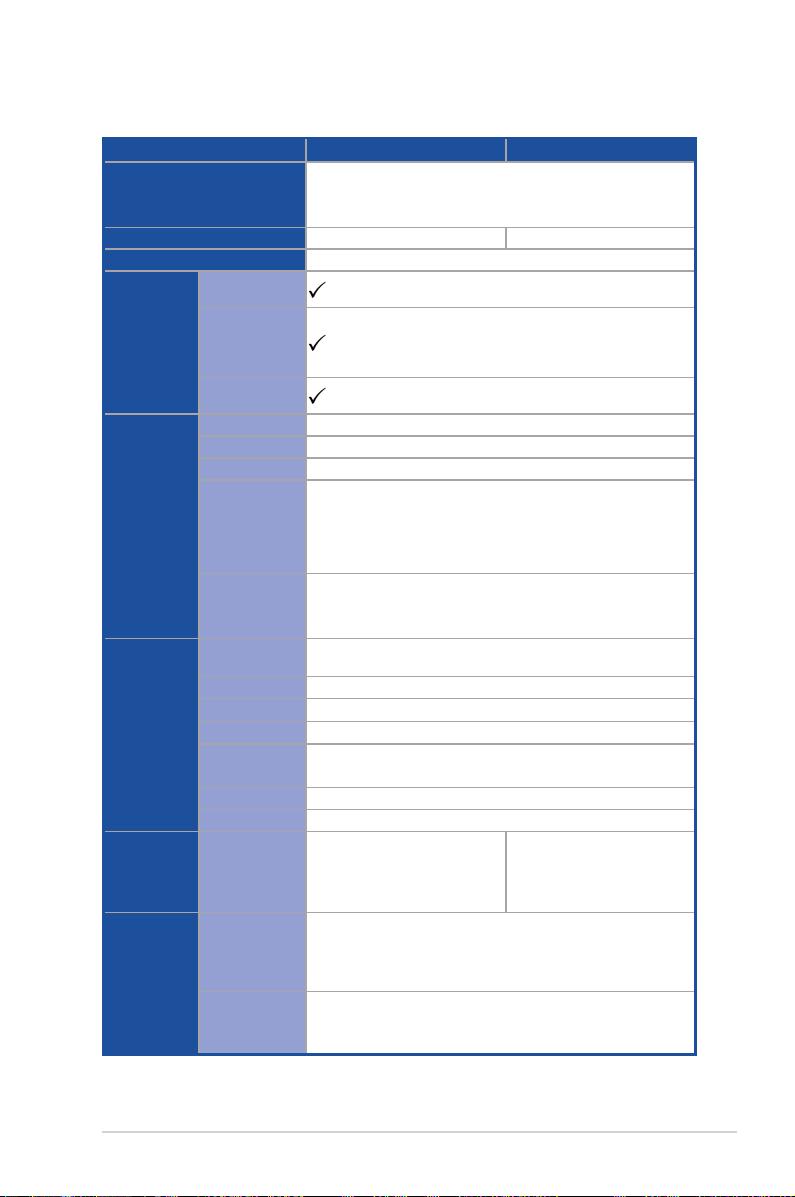
Z11PA-U12 Series specifications summary
Model Name Z11PA-U12/10G-2S Z11PA-U12
Processor Support /
System Bus
Core Logic
Form Factor
Fan Speed
Control
ASUS
Features
Memory
Expansion
Slots (follow
SSI Location
number)
Networking
Rack Ready
(Rack and
Pedestal dual
use)
ASUS Control
Center
Total Slots
Voltage
Capacity
Memory Type
Memory Size
Total PCI / PCI-E
Slots
Slot Location 1
Slot Location 2
Slot Location 3
Slot Location 4
Additional Slot 1
Additional Slot 2
LAN
SATA Controller
Storage
SAS Upgrade
1 x Socket P0 (LGA 3647)
1st Gen Intel® Xeon® processor Scalable Family
2nd Gen Intel® Xeon® processor Scalable Family
Intel® C622 PCH
ATX, 12" x 9.6" (EEB Mounting Hole Locations)
12 (6-channel per CPU, 12 DIMM per CPU)
1.2 V
Maximum up to 1536GB
DDR4 2933 (1 DIMM per Channel)
DDR4 2666 / 2400 / 2133 RDIMM / LRDIMM / 3DS DIMM
* 2933MHz will drop to 2666MHz when using 2DPC configurations.
** Refer to www.asus.com for the latest memory AVL update
4GB, 8GB, 16GB, 32GB (RDIMM)
32GB, 64GB (LRDIMM)
64GB, 128GB (LRDIMM 3DS)
4
1 x PCI-E x8 (x4 Gen3 Link)
1 x PCI-E x16 (x16 Gen3 Link)
1 x PCI-E x8 (x8 Gen3 Link)
1 x PCI-E x16 (x16 Gen3 Link)
(Auto switch to x8 Gen3 Link if slot 3 is occupied) (support riser)
M.2(NGFF) support (PCIe x2 Gen3 Link or SATA x1))
Oculink connectors support (PCIe x4 Gen3 on each slot)
2 x Intel I210AT
2 x 10G SFP+ LAN
(10G SKU only)
1 x Management Port
Intel® C620 series
13 x SATA 6Gb/s ports (3 x mini SAS HD + 1 x SATA)
1 x M.2 (PCIe x2 Gen3 Link or SATA x1) connector ;
NGFF Type 2280
Optional kits:
ASUS PIKE II 3008 8-port SAS 12G RAID card
ASUS PIKE II 3108 8-port SAS 12G HW RAID card
(continued on the next page)
Intel® C621 PCH
2 x Intel I210AT
1 x Management Port
xi
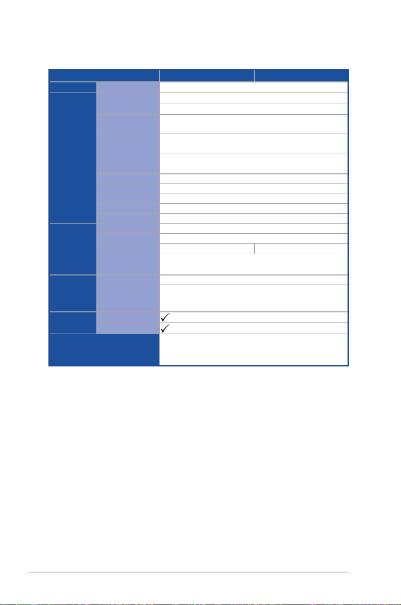
Z11PA-U12 Series specifications summary
Model Name Z11PA-U12/10G-2S Z11PA-U12
Graphic
Onboard I/O
Connectors
Rear I/O
Connectors
Management
Solution
Monitoring
Environment
VGA
TPM Header
PSU Connector
Management
connector
USB Connectors
Fan Header
SMBus
Chassis Intruder
Front LAN LED
Serial Port Header
M.2 Connector
VROC Key Header
VGA Port
External USB Port
SFP+
RJ-45
Software
Out of Band
Remote
Management
CPU Temperature
FAN RPM
Aspeed AST2500 64MB
1
24-pin SSI power connector + 8-pin SSI 12V
Onboard ASMB9-iKVM
1 x USB 3.0 pin header (up to 2 devices)
1 x USB 2.0 pin header (up to 2 devices)
6 x 4-pin
1
1
2
1
1 x NGFF Type 2242, 2260, 2280
1
1
2 x USB 3.0 ports
2 x SFP+ —
2 x GbE LAN
1 x Mgmt LAN
ASUS Control Center
ASMB9-iKVM for KVM-over-Internet
Operation temperature:
Non operation temperature:
Non operation humidity:
10°C ~ 35°C
-40°C ~ 70°C
20% ~ 90% (Non condensing)
* Specifications are subject to change without notice.
xii

Chapter 1: Product Introduction
Product Introduction
This chapter describes the motherboard features and the new
technologies it supports.
1
1.1 Welcome!
Congratulations and thank you for buying an ASUS® Z11PA-U12 Series motherboard!
The motherboard delivers a host of new features and latest technologies, making it another
standout in the long line of ASUS quality motherboards!
Before you start installing the motherboard and hardware devices on it, check the items in
your package with the list below.
1.2 Package contents
Check your motherboard package for the following items.
Standard Gift Box Pack Standard Bulk Pack
I/O Shield
SATA 6G cable
Application CD
Packaging Quantity
Optional items Description
PIKE II 3008 LSI 8-port SAS 12G RAID card
PIKE II 3108
PEM-FDR
PEB-10G/57840-2S
PEB-10G/57811-1S
Support DVD
If any of the above items is damaged or missing, contact your retailer.
LSI 8-port SAS 12G HW RAID card
Mellanox ConnectX-3 FDR card
Dual port 10G SFP+ Ethernet Adapter
Single port 10G SFP+ Ethernet Adapter
1 1
1 1 1 piece per carton
1 piece per carton 10 pieces per carton
1-2
Chapter 1: Product Introduction

1.3 Serial number label
Before requesting support from the ASUS Technical Support team, you must take note of
the motherboard's serial number containing 12 characters xxS2xxxxxxxx shown in the gure
below. With the correct serial number of the product, ASUS Technical Support team members
can then offer a quicker and satisfying solution to your problems.
Z11PA-U12 Series
xxS2xxxxxxxx
Made
in
China
合格
1.4 Special features
1.4.1 Product highlights
Latest Processor Technology
The motherboard supports Intel Xeon® processor scalable family which provides compelling
IPC increases for legacy performance improvements, oating point improvement, easier
multi-core programming, and with next-generation processor power management.
Intel® AVX 512
Intel® AVX 512 extends 512-bit vector support for integer vector operations, doubles
xed point arithmetic throughput, adds support for new vector gather, permutes/blend,
vector shifts resulting in xed and oating-point algorithm improvements. Also, Intel's new
microarchitecture doubles the cache bandwidth at L1/L2 to support higher FLOPS and
contributes to greater performance in signal and image processing applications.
Next Generation of processor power management
Intel® Xeon processor scalable family enhances the processor power management with the
features of Energy Efcient Turbo, Uncore Frequency Scaling, and Per-Core P-state. Also,
the Integrated Voltage Regulator enables generational performance and power improvements
that the standard VR solutions cannot provide.
DDR4 memory support
The motherboard supports DDR4 memory that features faster clock frequencies and higher
data transfer rates of 2133 MT/s to 2666 MT/s (million transfers per second). DDR4 offers a
lower voltage standard of 1.2V that reduces memory power demand and provides improved
performance.
Z11PA-U12 Series
1-3

M.2 Support
This motherboard features the M.2 slot, which shares bandwidth with the SATA 6Gb/s port
and is dedicated to the operating system.
PCI Express 3.0
PCI Express 3.0 (PCIe 3.0) is the PCI Express bus standard that provides an optimal
graphics performance, unprecedented data speed, and seamless transition with its complete
backward compatibility to PCIe 2.0 devices.
Intel® I210AT LAN Solution
The motherboard comes with two Gigabit LAN controllers and ports which provide a total
solution for your networking needs. The onboard Intel® I210AT Gigabit LAN controllers use
the PCI Express interface and could achieve network throughput close to Gigabit bandwidth.
Intel® C620 Series Chipset
The Intel® C620 series chipset supports with enterprise class features which is targeted for
Cloud and Storage applications. It is optimized and validated to work with the latest Xeon
processor scalable family, compared with the last generation, it also reduces the TDP,
supports USB 3.0 with up to 14 ports for SATA and SSATA thus bringing more features and
benets to the target users.
®
Serial ATA III technology
The motherboard supports the Serial ATA III technology through the Serial ATA interface
and Intel® C621 / C622 chipset, delivering up to 6 Gb/s data transfer rates. It also provides
enhanced scalability, faster data retrieval, and double the bandwidth of current bus systems.
Temperature, fan, and voltage monitoring
The CPU temperature is monitored to prevent overheating and damage. The system fan
rotations per minute (RPM) is monitored for timely failure detection. The chip monitors the
voltage levels to ensure a stable supply of current for critical components.
1.4.2 Innovative ASUS features
ASUS Fan Speed control technology
The ASUS Fan Speed control technology smartly adjusts the fan speeds according to the
system loading to ensure a quiet, cool, and efcient operation.
1-4
Chapter 1: Product Introduction

Chapter 2: Hardware Information
Hardware Information
This chapter lists the hardware setup procedures that you have
to perform when installing system components. It includes
description of the jumpers and connectors on the motherboard.
2

2.1 Before you proceed
Take note of the following precautions before you install any motherboard component or
change any motherboard settings.
• Unplug the power cord from the wall socket before touching any component.
• Use a grounded wrist strap or touch a safely grounded object or a metal object, such
as the power supply case, before handling components to avoid damaging them due
to static electricity.
• Hold components by the edges to avoid touching the ICs on them.
• Whenever you uninstall any component, place it on a grounded antistatic pad or in the
bag that came with the component.
• Before you install or remove any component, ensure that the power supply is switched
off or the power cord is detached from the power supply. Failure to do so may cause
severe damage to the motherboard, peripherals, and/or components.
2-2
Chapter 2: Hardware Information
2.2 Motherboard overview
Before you install the motherboard, study the conguration of your chassis to ensure that the
motherboard ts into it.
To optimize the features of your motherboard, we highly recommend that you install it in an
ATX 2.2 compliant chassis.
Ensure to unplug the chassis power cord before installing or removing the motherboard.
Failure to do so can cause you physical injury and damage motherboard components!
2.2.1 Placement direction
When installing the motherboard, ensure that you place it into the chassis in the correct
orientation. The edge with external ports goes to the rear part of the chassis as indicated in
the image below.
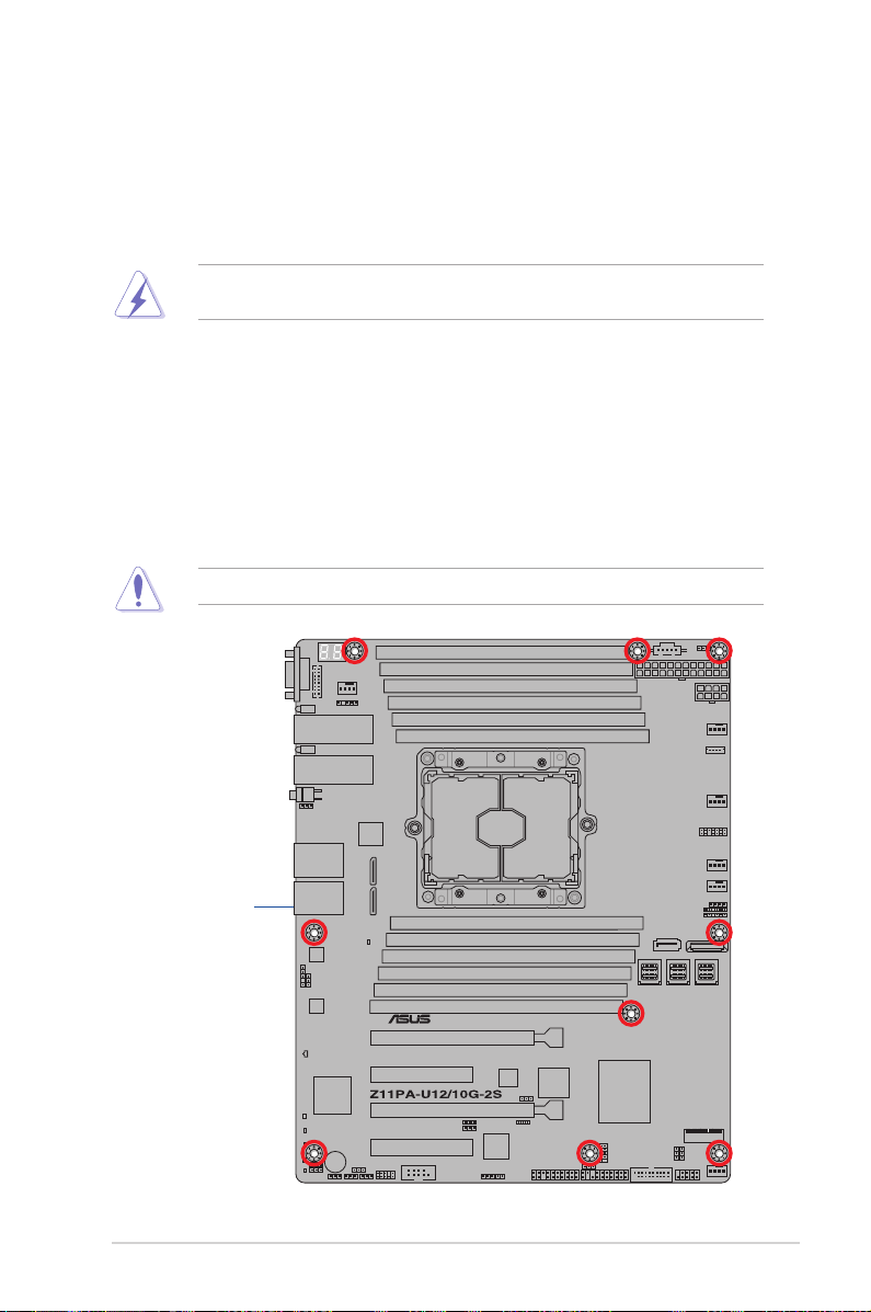
2.2.2 Screw holes
Place nine (9) screws into the holes indicated by circles to secure the motherboard to the
chassis.
DO NOT overtighten the screws! Doing so can damage the motherboard.
Place this side towards
the rear of the chassis
Z11PA-U12 Series
2-3
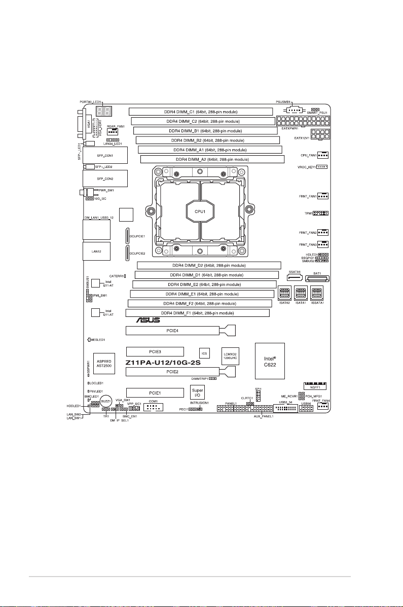
2.2.3 Motherboard layout
Z11PA-U12/10G-2S
2-4
Chapter 2: Hardware Information
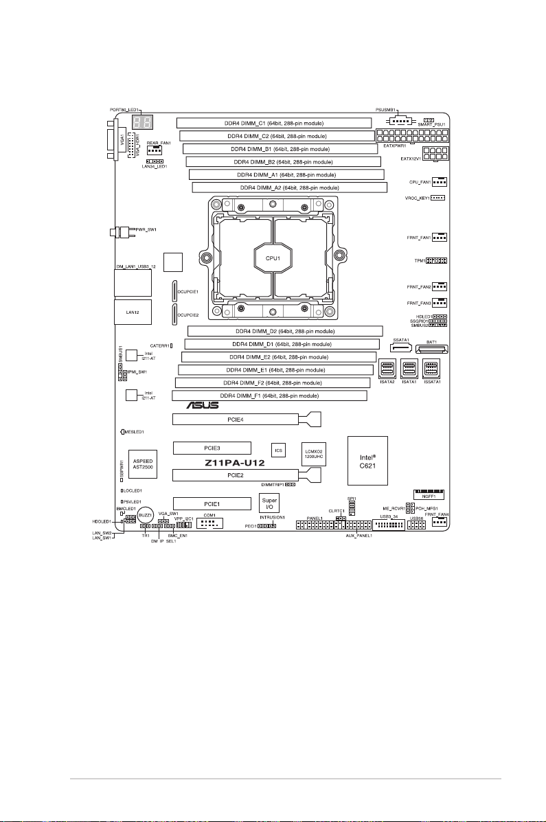
Z11PA-U12
Z11PA-U12 Series
2-5
2.2.4 Layout contents
Slots/Sockets
1. CPU socket 2-8
2. DDR4 sockets 2-10
3. PCI Express x16 / PCI Express x8 2-12
Onboard LEDs
1. Standby Power LED (SBPWR1) 2-16
2. Baseboard Management Controller LED (BMCLED1) 2-16
3. CATT LED (CATERR1)
4. Hard disk activity LED (HDDLED1)
5. Message LED (MESLED1)
6. Location LED (LOCLED1) 2-18
7. Q-Code LEDs (PORT80_LED1) 2-19
Jumpers
1. Clear RTC RAM (CLRTC1) 2-19
2. VGA controller setting (3-pin VGA_SW1) 2-20
3. LAN controller setting (3-pin LAN_SW1, LAN_SW2)
4. ME rmware force recovery setting (3-pin ME_RCVR1) 2-21
5. DDR4 thermal event setting (3-pin DIMMTRIP1) 2-21
6. PCH_MFG1 setting (3-pin PCH_MFG1) 2-22
7. Smart Ride Through (SmaRT) setting (3-pin SMART_PSU1) 2-22
8. DMLAN setting (3-pin DM_IP_SEL1) 2-23
9. IPMI SW setting (3-pin IPMI_SW1) 2-23
10. Baseboard Management Controller setting (3-pin BMC_EN1) 2-24
Page
Page
2-17
2-17
2-18
Page
2-20
2-6
Chapter 2: Hardware Information

Internal connectors
Page
1. Serial ATA 6.0/3.0 Gb/s connector (7-pin SSATA1) 2-27
2. Mini-SAS HD connector (ISATA1-2; ISSATA1) 2-27
3. M.2 (NGFF) connector (NGFF1)
2-28
4. Trusted Platform Module connector (14-1 pin TPM1) 2-28
5. USB 2.0 connector (10-1 pin USB56) 2-29
6. USB 3.0 connector (20-1 pin USB3_34) 2-29
7. Power Supply SMBus connector (5-pin PSUSMB1) 2-30
8. Serial port connector (10-1 pin COM1) 2-30
9. CPU, front, and rear fan connectors (4-pin CPU_FAN1, FRNT_FAN1-4,
REAR_FAN1)
2-31
10. Hard disk activity LED connector (4-pin HDLED1) 2-31
11. EATX power connectors (24-pin EATXPWR, 8-pin EATX12V1) 2-32
12. LAN34_LED connector (5-1 pin LAN34_LED1) 2-32
13. System panel connector (20-1 pin PANEL1) 2-33
14. Auxiliary panel connector (20-2 pin AUX_PANEL1) 2-34
15. VPP_I2C1 connector (10-1 pin VPP_I2C1) 2-35
16. Chassis Intrusion (2-pin INTRUSION) 2-35
17. OCUPCIE connectors (OCUPCIE1-2) 2-36
18. System Management Bus (SMBUS) connectors (5-1 pin SMBUS1;
6-1 pin SMBUS2)
2-36
19. Serial General Purpose Input/Output connector (6-1 pin SSGPIO1) 2-37
20. VGA connector (16-pin VGA_HDR1) 2-37
21. VROC_KEY connector (4-pin VROC_KEY1) 2-38
22. Thermal sensor cable connector (3-pin TR1) 2-38
Z11PA-U12 Series
2-7
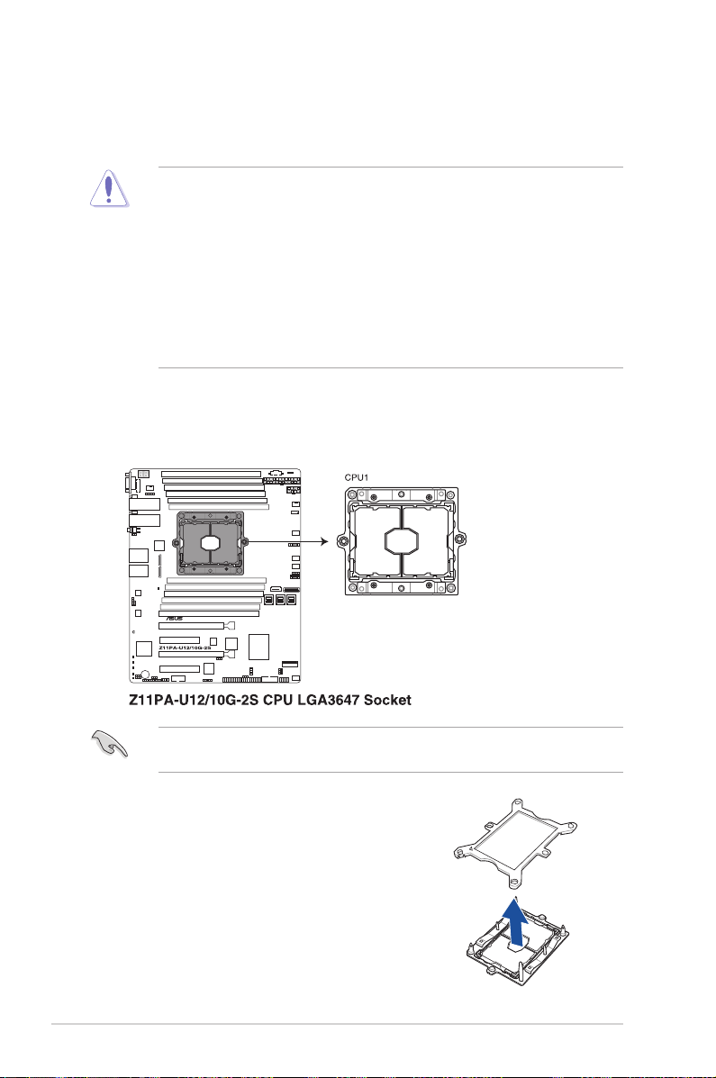
2.3 Central Processing Unit (CPU)
The motherboard comes with a surface mount Socket P0 (LGA 3647) designed for the Intel
Xeon® processor product family.
• Upon purchase of the motherboard, ensure that the PnP cap is on the socket and
the socket contacts are not bent. Contact your retailer immediately if the PnP cap
is missing, or if you see any damage to the PnP cap/socket contacts/motherboard
components. ASUS will shoulder the cost of repair only if the damage is shipment/
transit-related.
• Keep the cap after installing the motherboard. ASUS will process Return Merchandise
Authorization (RMA) requests only if the motherboard comes with the cap on the
Socket P0 (LGA 3647).
• The product warranty does not cover damage to the socket contacts resulting from
incorrect CPU installation/removal, or misplacement/loss/incorrect removal of the PnP
cap.
2.3.1 Installing the CPU and heatsink
To install a CPU:
1. Locate the CPU socket on the motherboard.
®
Before installing the CPU, ensure that the socket box is facing toward you and the triangle
mark is on the top-right position.
2. Remove the PNP cap from the CPU socket.
2-8
Chapter 2: Hardware Information
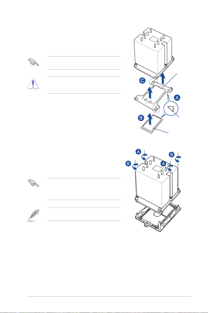
3. Align the triangle mark on the CPU with the
triangle mark on the CPU Carrier (A), then install
the CPU into the CPU Carrier until it clicks rmly
into place (B), and then install the CPU Carrier
into the heatsink until it clicks rmly in place (C).
Ensure that the triangle mark on the CPU
matches the triangle mark on the CPU Carrier.
Apply the Thermal Interface Material to the CPU
heatsink and CPU before you install the heatsink
and fan, if necessary.
4. Twist each of the four screws with a screwdriver
just enough to attach the heatsink to the
motherboard. When the four screws are attached,
tighten them one by one in a diagonal sequence
to completely secure the heatsink.
CPU Carrier
Triangle mark
CPU
The CPU and heatsink assembly ts in only one
correct orientation. DO NOT force the CPU and
heatsink assembly into the socket to prevent
damaging the CPU pins on the socket.
The heatsink screws are T30 models. A torque
value of 12 inch-lbf is recommended.
Z11PA-U12 Series
2-9
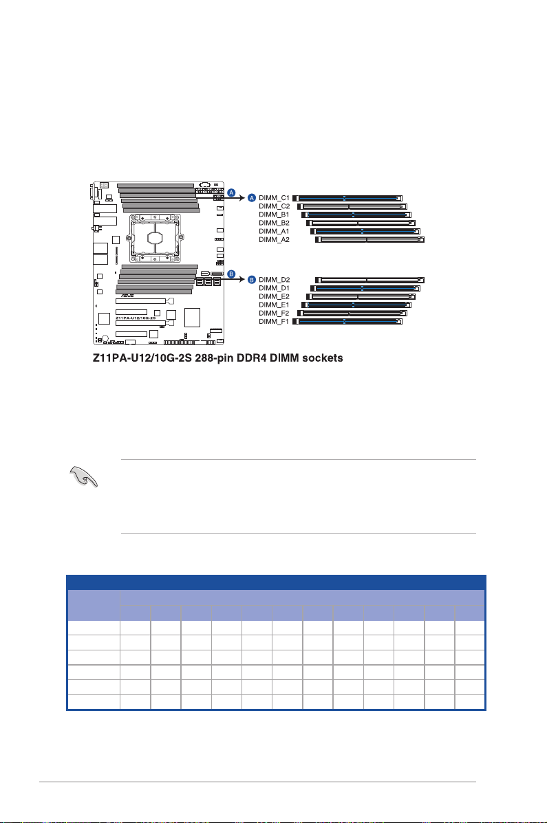
2.4 System memory
2.4.1 Overview
The motherboard comes with twelve (12) Double Data Rate 4 (DDR4) Dual Inline Memory
Modules (DIMM) sockets.
The gure illustrates the location of the DDR4 DIMM sockets:
2.4.2 Memory Configurations
You may install 4 GB, 8 GB, 16 GB, and 32 GB RDIMMs or 32 GB and 64 GB LR-DIMMs into
the DIMM sockets using the memory congurations in this section.
• Refer to ASUS Server AVL for the updated list of compatible DIMMs.
• When installing DIMMs, always start from slot A1.
• Always install DIMMs with the same CAS latency. For optimum compatibility, it is
recommended that you obtain memory modules from the same vendor.
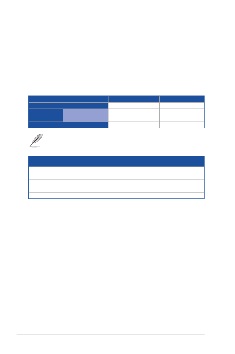
You can refer to the following recommended memory population:
Recommended Memory configuration
DIMM
A2 A1 B2 B1 C2 C1 D2 D1 E2 E1 F2 F1
1 DIMM
2 DIMMs
4 DIMMs
6 DIMMs
8 DIMMs
12 DIMMs
2-10
-
-
-
-
P P
P P
P
- - - - - - - - - -
P
- - - - -
P
P
P
-
-
-
P P P P P P P P P P
P
P
- - -
P
-
P P P
-
P
- - - -
P
P
-
P
-
-
-
- -
P
-
P
-
Chapter 2: Hardware Information
P
P
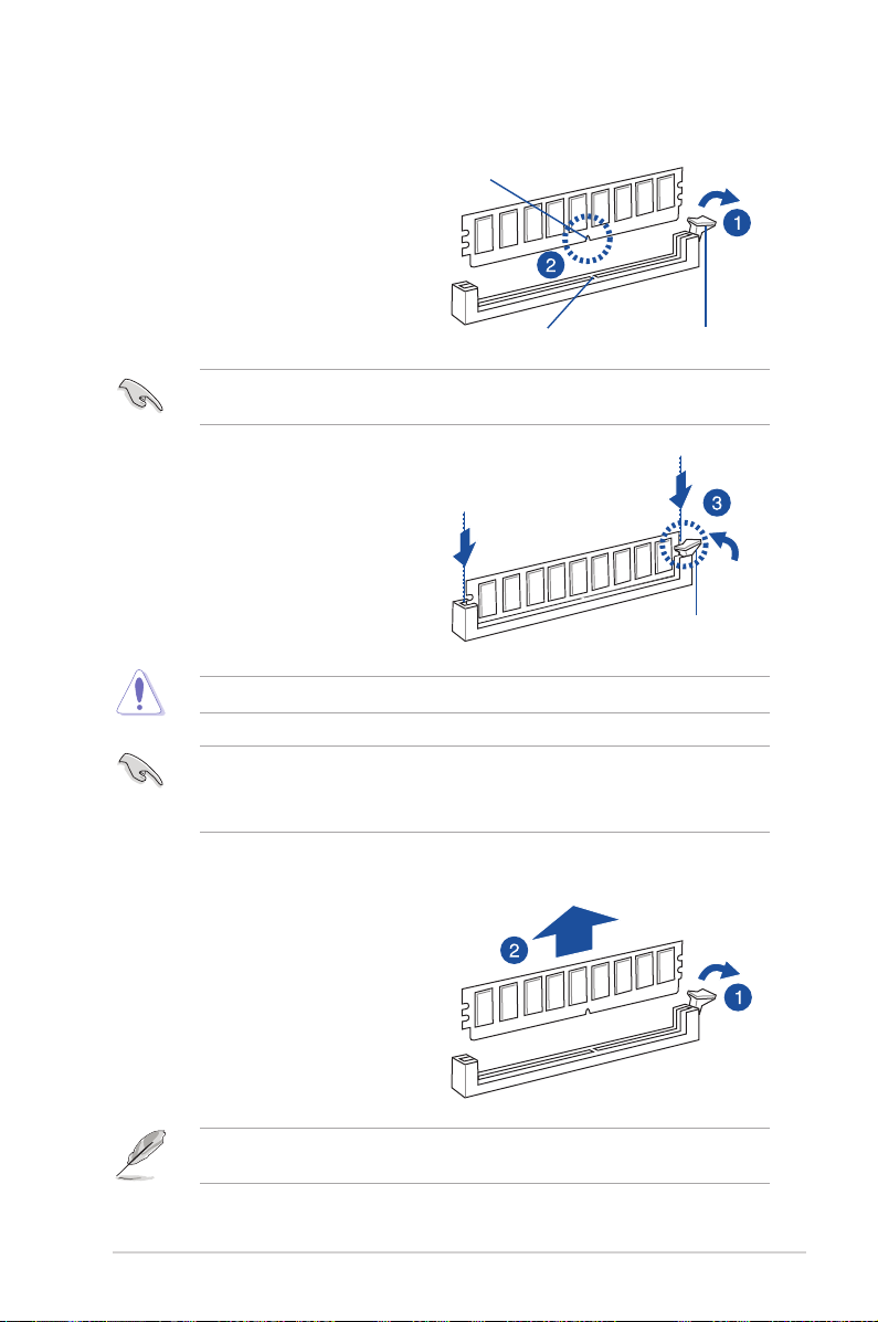
2.4.3 Installing a DIMM on a single clip DIMM socket
1. Press the retaining clip outward to
unlock the DIMM socket.
2. Align a DIMM on the socket such that
the notch on the DIMM matches the
DIMM slot key on the socket.
A DIMM is keyed with a notch so that it ts in only one direction. DO NOT force a DIMM into
a socket in the wrong direction to avoid damaging the DIMM.
3. Hold the DIMM at both ends then
insert the DIMM into the socket.
Apply force to both ends of the DIMM
simultaneously until the retaining clip
clicks into place and the DIMM is
seated securely in place.
Always insert the DIMM into the socket VERTICALLY to prevent DIMM notch damage.
• To install two or more DIMMs, refer to the user guide bundled with the motherboard
package.
• Refer to the user guide for qualied vendor lists of the memory modules.
DIMM notch
DIMM slot key
Unlocked retaining clip
Locked Retaining Clip
Removing a DIMM from a single clip DIMM socket
1. Press the retaining clip outward to
unlock the DIMM.
2. Remove the DIMM from the socket.
Support the DIMM lightly with your ngers when pressing the retaining clips. The DIMM
might get damaged when it ips out with extra force.
Z11PA-U12 Series
2-11

2.5 Expansion slots
In the future, you may need to install expansion cards. The following subsections describe the
slots and the expansion cards that they support.
Ensure to unplug the power cord before adding or removing expansion cards. Failure to do
so may cause you physical injury and damage motherboard components.
2.5.1 Installing an expansion card
To install an expansion card:
1. Before installing the expansion card, read the documentation that came with it and
make the necessary hardware settings for the card.
2. Remove the system unit cover (if your motherboard is already installed in a chassis).
3. Remove the bracket opposite the slot that you intend to use. Keep the screw for later
use.
4. Align the card connector with the slot and press rmly until the card is completely
seated on the slot.
5. Secure the card to the chassis with the screw you removed earlier.
6. Replace the system cover.
2.5.2 Configuring an expansion card
After installing the expansion card, congure it by adjusting the software settings.
1. Turn on the system and change the necessary BIOS settings, if any. See
information on BIOS setup.
2. Assign an IRQ to the card.
Chapter 4
for
Refer to the table
more information.
Standard Interrupt assignments
3. Install the software drivers for the expansion card.
When using PCIe cards on shared slots, ensure that the drivers support “Share IRQ” or that
the cards do not need IRQ assignments. Otherwise, conicts may arise between the two
PCIe groups, making the system unstable and the card inoperable.
2-12
in section
Interrupt assignments
for
Chapter 2: Hardware Information

2.5.3 Interrupt assignments
Standard Interrupt assignments
IRQ Priority Standard function
0 1 System Timer
1 2 Keyboard Controller
2 - Programmable Interrupt
3* 11 Communications Port (COM2)
4* 12 Communications Port (COM1)
5* 13 --
6 14 Floppy Disk Controller
7* 15 --
8 3 System CMOS/Real Time Clock
9* 4 ACPI Mode when used
10* 5 IRQ Holder for PCI Steering
11* 6 IRQ Holder for PCI Steering
12* 7 PS/2 Compatible Mouse Port
13 8 Numeric Data Processor
14* 9 Primary IDE Channel
15* 10 Secondary IDE Channel
* These IRQs are usually available for ISA or PCI devices.
2.5.4 PCI Express x16 slot (x16 link)
The onboard PCIE4 and PCIE2 slots provide two x16 Gen3 link to CPU1 and only PCIE4
supports auto switches to x8 link if PCIE3 is occupied. These two slots support VGA cards
and various server class high performance add-on cards.
2.5.5 PCI Express x8 slot (x8 link)
The onboard PCIE3 slot provides one x8 Gen3 link to CPU1. This slot supports VGA cards
and various server class high performance add-on cards.
2.5.6 PCI Express x8 slot (x4 link)
The onboard PCIE1 slot provides one x4 Gen3 link to CPU1 This slot supports various server
class high performance add-on cards.
Z11PA-U12 Series
2-13
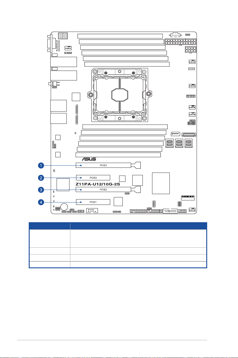
No. (Slot location) Short description
PCI-E x16 (x16 Gen3 Link)
1 PCIE4
(Auto switch to x8 Gen3 Link if slot 3 is occupied)
(support riser)
2 PCIE3 PCI-E x8 (x8 Gen3 Link)
3 PCIE2 PCI-E x16 (x16 Gen3 Link)
4 PCIE1 PCI-E x8 (x4 Gen3 Link)
2-14
Chapter 2: Hardware Information
 Loading...