

Page 1
V-Series P5G45
R
R
ASUS PC (Desktop Barebone)
Installation Manual
Page 2

E4142
First Edition V1
October 2008
Copyright © 2008 ASUSTeK Computer INC. All Rights Reserved.
No part of this manual, including the products and software described in it, may be reproduced,
transmitted, transcribed, stored in a retrieval system, or translated into any language in any form or by any
means, except documentation kept by the purchaser for backup purposes, without the express written
permission of ASUSTeK Computer INC. (“ASUS”).
Product warranty or service will not be extended if: (1) the product is repaired, modied or altered, unless
such repair, modication of alteration is authorized in writing by ASUS; or (2) the serial number of the
product is defaced or missing.
ASUS PROVIDES THIS MANUAL “AS IS” WITHOUT WARRANTY OF ANY KIND, EITHER EXPRESS
OR IMPLIED, INCLUDING BUT NOT LIMITED TO THE IMPLIED WARRANTIES OR CONDITIONS OF
MERCHANTABILITY OR FITNESS FOR A PARTICULAR PURPOSE. IN NO EVENT SHALL ASUS, ITS
DIRECTORS, OFFICERS, EMPLOYEES OR AGENTS BE LIABLE FOR ANY INDIRECT, SPECIAL,
INCIDENTAL, OR CONSEQUENTIAL DAMAGES (INCLUDING DAMAGES FOR LOSS OF PROFITS,
LOSS OF BUSINESS, LOSS OF USE OR DATA, INTERRUPTION OF BUSINESS AND THE LIKE),
EVEN IF ASUS HAS BEEN ADVISED OF THE POSSIBILITY OF SUCH DAMAGES ARISING FROM ANY
DEFECT OR ERROR IN THIS MANUAL OR PRODUCT.
SPECIFICATIONS AND INFORMATION CONTAINED IN THIS MANUAL ARE FURNISHED FOR
INFORMATIONAL USE ONLY, AND ARE SUBJECT TO CHANGE AT ANY TIME WITHOUT NOTICE,
AND SHOULD NOT BE CONSTRUED AS A COMMITMENT BY ASUS. ASUS ASSUMES NO
RESPONSIBILITY OR LIABILITY FOR ANY ERRORS OR INACCURACIES THAT MAY APPEAR IN THIS
MANUAL, INCLUDING THE PRODUCTS AND SOFTWARE DESCRIBED IN IT.
Products and corporate names appearing in this manual may or may not be registered trademarks or
copyrights of their respective companies, and are used only for identication or explanation and to the
owners’ benet, without intent to infringe.
ii
Page 3

Table of contents
Notices ......................................................................................................... vi
Safety information ..................................................................................... vii
About this guide ....................................................................................... viii
System package contents ........................................................................... x
Chapter 1: System introduction
1.1 Welcome! ...................................................................................... 1-2
1.2 Front panel ................................................................................... 1-2
1.3 Rear panel ..................................................................................... 1-4
1.4 Internal components .................................................................... 1-8
Chapter 2: Basic installation
2.1 Preparation ................................................................................... 2-2
2.2 Before you proceed ..................................................................... 2-2
2.3 Removing the side cover and front panel assembly ................ 2-3
2.4 Central Processing Unit (CPU) ................................................... 2-4
2.4.1 Overview ......................................................................... 2-4
2.4.2 Installing CPU ................................................................. 2-4
2.4.3 Installing the CPU fan and heatsink assembly ................ 2-6
2.5 Installing a DIMM .......................................................................... 2-8
2.5.1 Overview ......................................................................... 2-8
2.5.2 Memory congurations .................................................... 2-9
2.5.3 Installing a DDR2 DIMM ............................................... 2-15
2.5.4 Removing a DDR2 DIMM ............................................. 2-15
2.6 Expansion slots .......................................................................... 2-16
2.6.1 Installing an expansion card ......................................... 2-16
2.6.2 Conguring an expansion card ..................................... 2-16
2.6.3 PCI slots ........................................................................ 2-18
2.6.4 PCI Express x1 slot ....................................................... 2-18
2.6.5 PCI Express x16 slot ..................................................... 2-18
2.7 Installing an optical drive .......................................................... 2-19
2.8 Installing a hard disk drive ........................................................ 2-20
2.9 Installing the card reader .......................................................... 2-22
2.10 Installingaoppydiskdrive ..................................................... 2-24
2.11 Re-connecting cables ................................................................ 2-25
2.12 Reinstalling the cover ................................................................ 2-26
iii
Page 4

Table of contents
Chapter 3: Starting up
3.1 Installing an operating system ................................................... 3-2
3.2 Powering up .................................................................................. 3-2
3.3 Support DVD information ............................................................ 3-2
3.3.1 Running the support DVD ............................................... 3-3
3.3.2 Utilities menu .................................................................. 3-4
3.3.3 Manual menu .................................................................. 3-6
3.3.4 Make Disk menu ............................................................. 3-7
3.3.5 ASUS Contact information .............................................. 3-7
3.3.6 Other information ............................................................ 3-8
3.4 Software information ................................................................. 3-10
Chapter 4: Motherboard introductiomn
4.1 Introduction .................................................................................. 4-2
4.2 Motherboard layout ...................................................................... 4-2
4.3 Jumpers ........................................................................................ 4-3
4.3 Connectors ................................................................................... 4-6
Chapter 5: BIOS setup
5.1 Managing and updating your BIOS ............................................ 5-2
5.1.1 ASUS Update utility ........................................................ 5-2
5.1.2 Creating a bootable oppy disk ....................................... 5-5
5.1.3 ASUS EZ Flash 2 utility ................................................... 5-6
5.1.4 AFUDOS utility ................................................................ 5-7
5.1.5 ASUS CrashFree BIOS 3 utility ...................................... 5-9
5.2 BIOS setup program .................................................................. 5-10
5.2.1 BIOS menu screen .........................................................5-11
5.2.2 Menu bar ........................................................................5-11
5.2.3 Navigation keys ..............................................................5-11
5.2.4 Menu items ................................................................... 5-12
5.2.5 Sub-menu items ............................................................ 5-12
5.2.6 Conguration elds ....................................................... 5-12
5.2.7 Pop-up window ............................................................. 5-12
5.2.8 Scroll bar ....................................................................... 5-12
5.2.9 General help ................................................................. 5-12
iv
Page 5

Table of contents
5.3 Main menu .................................................................................. 5-13
5.3.1 System Time ................................................................. 5-13
5.3.2 System Date ................................................................. 5-13
5.3.3 Legacy Diskette A ......................................................... 5-13
5.3.4 SATA 1–6 ...................................................................... 5-14
5.3.5 Storage Conguration ................................................... 5-15
5.3.6 AHCI Conguration ....................................................... 5-16
5.3.7 System Information ....................................................... 5-17
5.4 Ai Tweaker menu ........................................................................ 5-18
5.4.1 Congure System performance Settings ...................... 5-18
5.5 Advanced menu ......................................................................... 5-25
5.5.1 CPU Conguration ........................................................ 5-25
5.5.2 Chipset .......................................................................... 5-27
5.5.3 Onboard Devices Conguration .................................... 5-28
5.5.4 USB Conguration ........................................................ 5-29
5.5.5 PCIPnP ......................................................................... 5-30
5.6 Power menu ................................................................................ 5-31
5.6.1 Suspend Mode .............................................................. 5-31
5.6.2 Repost Video on S3 Resume ........................................ 5-31
5.6.3 ACPI 2.0 Support .......................................................... 5-31
5.6.4 ACPI APIC Support ....................................................... 5-31
5.6.5 APM Conguration ........................................................ 5-32
5.6.6 Hardware Monitor ......................................................... 5-33
5.7 Boot menu .................................................................................. 5-35
5.7.1 Boot Device Priority ...................................................... 5-35
5.7.2 Boot Settings Conguration .......................................... 5-36
5.7.3 Security ......................................................................... 5-37
5.8 Tools menu ................................................................................. 5-39
5.8.1 ASUS EZ Flash 2 .......................................................... 5-39
5.8.2 Express Gate ................................................................ 5-40
5.8.3 ASUS O.C. Prole ......................................................... 5-41
5.8.4 AI Net 2 ......................................................................... 5-42
5.9 Exit menu .................................................................................... 5-43
v
Page 6

Notices
Federal Communications Commission Statement
This device complies with Part 15 of the FCC Rules. Operation is subject to the
following two conditions:
•
This device may not cause harmful interference, and
•
This device must accept any interference received including interference that
may cause undesired operation.
This equipment has been tested and found to comply with the limits for a
Class B digital device, pursuant to Part 15 of the FCC Rules. These limits are
designed to provide reasonable protection against harmful interference in a
residential installation. This equipment generates, uses and can radiate radio
frequency energy and, if not installed and used in accordance with manufacturer’s
instructions, may cause harmful interference to radio communications. However,
there is no guarantee that interference will not occur in a particular installation. If
this equipment does cause harmful interference to radio or television reception,
which can be determined by turning the equipment off and on, the user is
encouraged to try to correct the interference by one or more of the following
measures:
•
Reorient or relocate the receiving antenna.
•
Increase the separation between the equipment and receiver.
•
Connect the equipment to an outlet on a circuit different from that to which the
receiver is connected.
•
Consult the dealer or an experienced radio/TV technician for help.
WARNING! The use of shielded cables for connection of the monitor to the
graphics card is required to assure compliance with FCC regulations. Changes
or modications to this unit not expressly approved by the party responsible for
compliance could void the user’s authority to operate this equipment.
Canadian Department of Communications Statement
This digital apparatus does not exceed the Class B limits for radio noise emissions
from digital apparatus set out in the Radio Interference Regulations of the
Canadian Department of Communications.
This class B digital apparatus complies with Canadian ICES-003.
vi
Page 7

Safety information
Electrical safety
•
To prevent electrical shock hazard, disconnect the power cable from the
electrical outlet before relocating the system.
•
When adding or removing devices to or from the system, ensure that the power
cables for the devices are unplugged before the signal cables are connected.
•
If the power supply is broken, do not try to x it by yourself. Contact a qualied
service technician or your retailer.
Operation safety
•
Before installing devices into the system, carefully read all the documentation
that came with the package.
•
Before using the product, make sure all cables are correctly connected and the
power cables are not damaged. If you detect any damage, contact your dealer
immediately.
•
To avoid short circuits, keep paper clips, screws, and staples away from
connectors, slots, sockets and circuitry.
•
Avoid dust, humidity, and temperature extremes. Do not place the product in
any area where it may become wet. Place the product on a stable surface.
•
If you encounter technical problems with the product, contact a qualied
service technician or your retailer.
Lithium-Ion Battery Warning
CAUTION: Danger of explosion if battery is incorrectly replaced. Replace
only with the same or equivalent type recommended by the manufacturer.
Dispose of used batteries according to the manufacturer’s instructions.
VORSICHT: Explosionsgetahr bei unsachgemäßen Austausch der Batterie.
Ersatz nur durch denselben oder einem vom Hersteller empfohlenem
ähnljchen Typ. Entsorgung gebrauchter Batterien nach Angaben des
Herstellers.
LASER PRODUCT WARNING
CLASS 1 LASER PRODUCT
vii
Page 8

About this guide
Audience
This guide provides general information and installation instructions about
the ASUS Vintage V-Series P5G45 barebone system. This guide is intended
for experienced users and integrators with hardware knowledge of personal
computers.
How this guide is organized
This guide contains the following parts:
1. Chapter 1: System introduction
This chapter gives a general description of the ASUS
V-Series P5G45. The chapter lists the system features, including introduction
on the front and rear panel, and internal components.
2. Chapter 2: Basic installation
This chapter provides step-by-step instructions on how to install components
in the system.
3. Chapter 3: Starting up
This chapter helps you power up the system and install drivers and utilities
from the support DVD.
4. Chapter 4: Motherboard information
This chapter gives information about the motherboard that comes with the
system. This chapter includes the motherboard layout, jumper settings, and
connector locations.
5. Chapter 5: BIOS information
This chapter tells how to change system settings through the BIOS Setup
menus and describes the BIOS parameters.
viii
Page 9

Conventions used in this guide
WARNING: Information to prevent injury to yourself when trying to
complete a task.
CAUTION: Information to prevent damage to the components when
trying to complete a task.
IMPORTANT: Instructions that you MUST follow to complete a task.
NOTE: Tips and additional information to aid in completing a task.
Wheretondmoreinformation
Refer to the following sources for additional information and for product and
software updates.
1. ASUS Websites
The ASUS websites worldwide provide updated information on ASUS
hardware and software products. Refer to the ASUS contact information.
2. Optional Documentation
Your product package may include optional documentation, such as warranty
yers, that may have been added by your dealer. These documents are not
part of the standard package.
ix
Page 10

System package contents
Check your V-Series P5G45 system package for the following items.
If any of the items is damaged or missing, contact your retailer immediately.
Item description
1. ASUS V-Series P5G45 barebone system with
• ASUS motherboatd
• Power supply unit
• ASUS chassis
2. Cable
• AC power cable
3. Support DVD
4. User guide
5. Telecom Adapter Card (Optional)
x
Page 11
R
R
Chapter 1
This chapter gives a general
description of the ASUS
V-Series P5G45. The chapter lists the
system features including introduction
on the front and rear panel, and
internal components.
System introduction
Page 12
1.1 Welcome!
R
Thank you for choosing the ASUS V-Series P5G45!
The ASUS V-Series P5G45 is an all-in-one barebone system with a versatile
home entertainment feature.
The system comes in a stylish casing and powered by the ASUS motherboard that
supports the Intel® Core™2 Extreme / Core™2 Duo / Core™2 Quad / Pentium®
dual-core / Celeron® processors in the 775-land package.
The system supports up to 8 GB of system memory using DDR2-1066/800/667
DIMMs. High-resolution graphics via integrated graphics controller or PCI Express
x16 slot, Serial ATA, USB 2.0, and 8-channel audio feature the system and take
you ahead in the world of power computing.
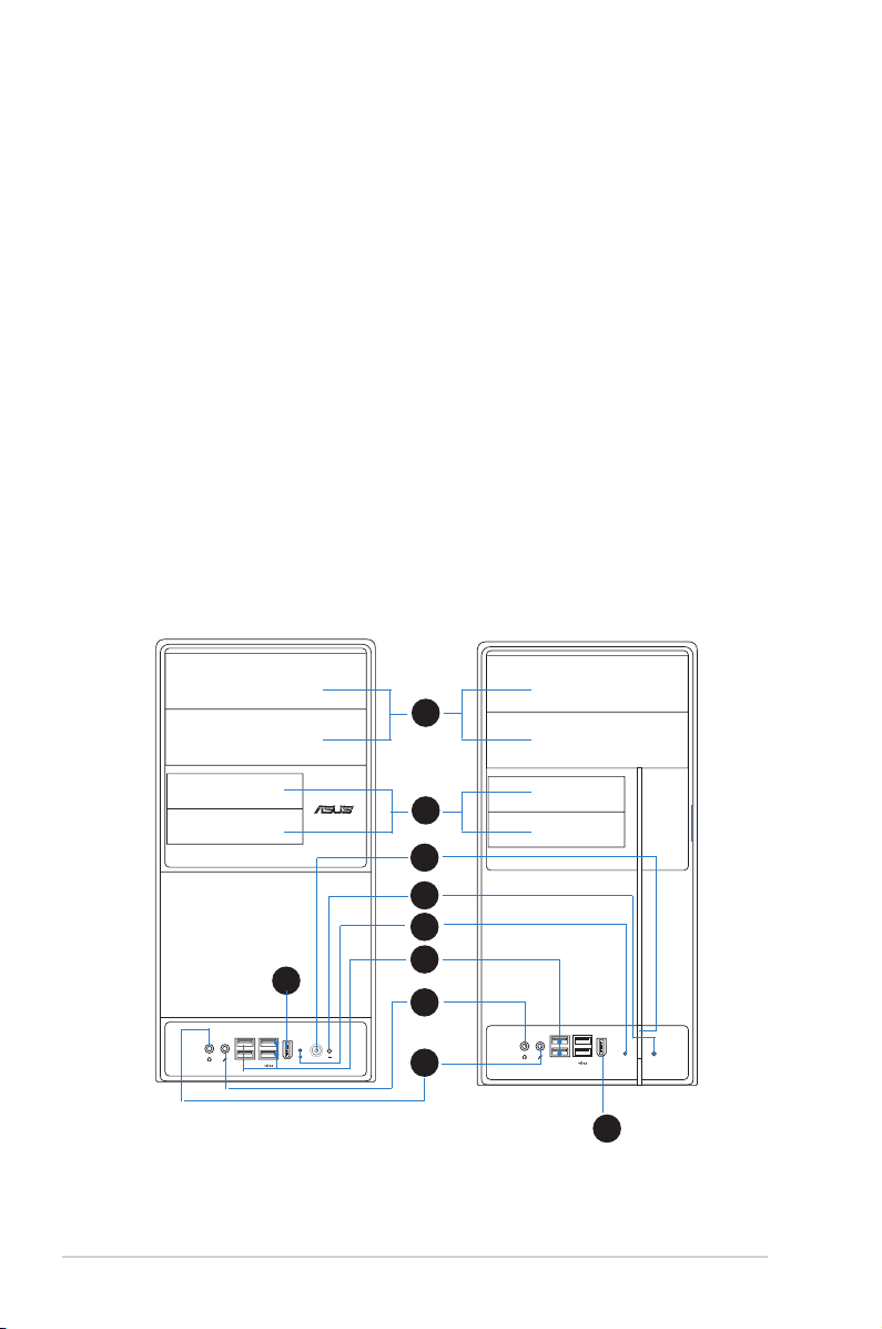
1.2 Front panel
The front panel includes the optical drive bays, oppy disk drive slot, power button,
and several I/O ports are located at the front panel.
1
2
3
4
5
9
1-2 Chapter 1: System introduction
6
7
8
9
Page 13

1. Two empty 5.25-inch bays. These bays are for IDE optical drives.
2. 3.5-inch drive bays. These slots are for 3.5-inch oppy or hard disk drives.
3. Power button. Press this button to turn the system on.
4. Reset button. Press this button to reboot the system without turning off the
power.
5. HDD LED. This LED lights up when data is read from or written to the hard
disk drive.
6. USB 2.0 ports. These Universal Serial Bus 2.0 (USB 2.0) ports are available
for connecting USB 2.0 devices such as a mouse, printer, scanner, camera,
PDA, and others.
7. Headphone port. This Line In (green) port connects a headphone with a
stereo mini-plug.
8. Microphone port. This Mic (pink) port connects a microphone.
9. IEEE1394 port.
This V-series provide V2/V3 two types of front panel for users to choose, please
refer to your product package for the front panel type you purchased.
1-3ASUS V-Series P5G45
Page 14
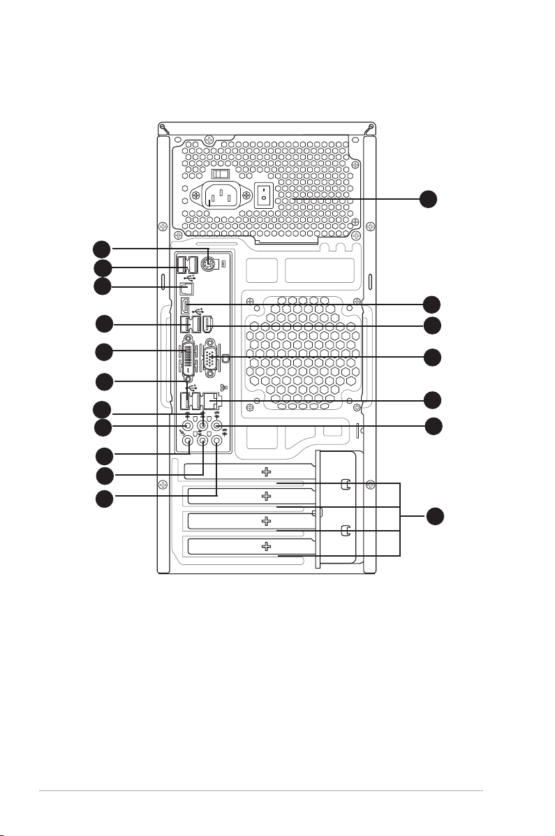
1.3 Rear panel
SPDIF OUT
10
11
12
1
2
4
6
7
8
9
3
14
15
13
5
16
DVI
HDMI
1394
17
18
The system rear panel includes the power connector and several I/O ports that
allow convenient connection of devices.
1. PS/2 keyboard port (purple). This port is for a PS/2 keyboard.
2. USB 2.0 ports 3 and 4. These 4-pin Universal Serial Bus (USB) ports are
available for connecting USB 2.0 devices.
3. Video Graphics Adapter (VGA) port. This 15-pin port is for a VGA monitor
or other VGA-compatible devices.
4. LAN (RJ-45) port. Supported by Gigabit LAN controller, this port allows
Gigabit connection to a Local Area Network (LAN) through a network hub.
Refer to the table below for the LAN port LED indications.
1-4 Chapter 1: System introduction
Page 15
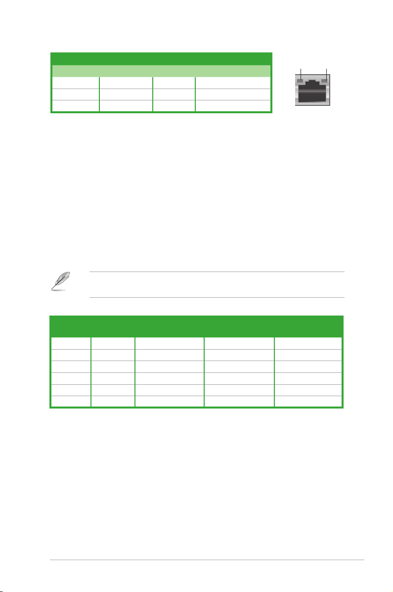
LAN port LED indications
LED
LAN port
SPEED
LED
Activity/Link Speed LED
Status Description Status Description
OFF No link OFF 10 Mbps connection
ORANGE Linked ORANGE 100 Mbps connection
BLINKING Data activity GREEN 1 Gbps connection
5. Rear Speaker Out port (black).
This port connects the rear speakers in a
ACT/LINK
4-channel, 6-channel, or 8-channel audio conguration.
6. Center/Subwoofer port (orange).
This port connects the center/subwoofer
speakers.
7. Line In port (light blue).
This port connects the tape, CD, DVD player, or
other audio sources.
8. Line Out port (lime). This port connects a headphone or a speaker. In
4-channel, 6-channel, and 8-channel conguration, the function of this port
becomes Front Speaker Out.
9. Microphone port (pink). This port connects a microphone.
10. Side Speaker Out port (gray). This port connects the side speakers in an
8-channel audio conguration.
Refer to the audio conguration table below for the function of the audio ports in
2, 4, 6, or 8-channel conguration.
Audio2,4,6,or8-channelconguration
Port
Light Blue Line In Line In Line In Line In
Lime Line Out Front Speaker Out Front Speaker Out Front Speaker Out
Pink Mic In Mic In Mic In Mic In
Orange – – Center/Subwoofer Center/Subwoofer
Black – Rear Speaker Out Rear Speaker Ou Rear Speaker Out
Gray – – – Side Speaker Out
11. USB 2.0 ports 1 and 2. These 4-pin Universal Serial Bus (USB) ports are
12. USB 2.0 ports 5 and 6. These 4-pin Universal Serial Bus (USB) ports are
13. DVI-D Out port. This port is for any DVI-D compatible device and is HDCP
Headset
2-channel
4-channel 6-channel 8-channel
available for connecting USB 2.0 devices.
available for connecting USB 2.0 devices.
compliant allowing playback of HD DVD, Blu-Ray and other protected
content.
1-5ASUS V-Series P5G45
Page 16

• This motherboard comes with multiple VGA output that features desktop
extension on two monitors. You can connect two monitors to any two of the
onboard VGA, DVI-D, and HDMI ports. Note that DVI-D/HDMI dual output
works in OS environment only and that during POST or BIOS setup, only
DVI-D output is valid.
• DVI-D cannot be converted to output RGB Signal to CRT and is not
compatible with DVI-I.
• To play HD DVD or Blu-Ray Disc, make sure to use an HDCP compliant
monitor.
14. HDMI Out port. This port is for a high-denition multimedia interface (HDMI)
connector.
• This motherboard comes with multiple VGA output that features desktop
extension on two monitors. You can connect two monitors to any two of the
onboard VGA, DVI-D, and HDMI ports. Note that DVI-D/HDMI dual output
works in OS environment only and that during POST or BIOS setup, only
DVI-D output is valid.
• Due to the Intel® VGA driver issue, the Windows® Display Settings menu
may offer some resolution options that your monitor does not support.
When you set a resolution not supported by your monitor, it will black out. If
this happens, wait 15 seconds for the system to return to its original setting
or restart the system and press F8 to enter Safe Mode. In Safe Mode,
change the display setting to 800 x 600, and then restart the system to
adjust the monitor resolution from the Windows® Display Settings menu.
• Due to the Intel® driver issue, some monitor resolution settings will
lead to monitor overscan or underscan. Refer to the next page for the
troubleshooting on monitor overscan/underscan problem
• Playback of HD DVD and Blu-Ray Discs
The speed and bandwidth of the CPU/Memory, DVD player, and drivers will
affect the playback quality. Following is a conguration example for your
reference. Using the CPU/Memory of higher speed and bandwidth with the
higher-version DVD player and drivers will upgrade the playback quality.
CPU: Intel Core 2 Duo 2.4GHz
DIMM: DDR2-800 1GB
Playback software - CyberLink PowerDVD Ultra v8.0 1730.05
• To play HD DVD or Blu-Ray Disc, make sure to use an HDCP compliant
monitor.
• You can only play HD DVD or Blu-Ray Disc under Windows® Vista™ OS.
1-6 Chapter 1: System introduction
Page 17
15. Expansion slot covers. Remove these covers when installing expansion
cards.
16. Power supply unit fan vent. This vent is for the PSU fan that provides
ventilation inside the power supply unit.
17. Optical S/PDIF Out port. This port connects an external audio output device
via an optical S/PDIF cable.
18. IEEE 1394a port. This 6-pin IEEE 1394a port provides high-speed
connectivity for audio/video devices, storage peripherals, PCs, or portable
devices.
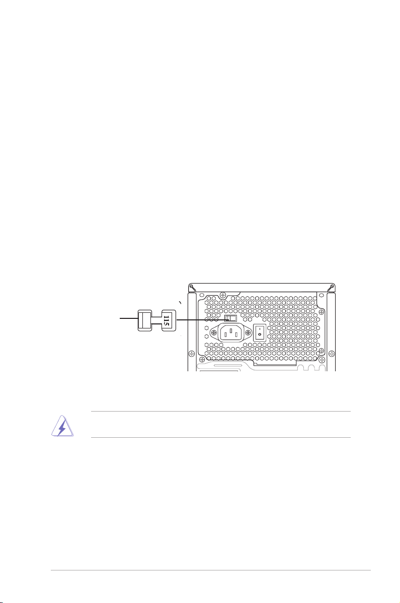
Voltage selector
The PSU has a 115 V/230 V voltage selector switch located beside the power
connector. Use this switch to select the appropriate system input voltage according
to the voltage supply in your area.
If the voltage supply in your area is 100-127 V, set this switch to 115 V.
If the voltage supply in your area is 200-240 V, set this switch to 230 V.
115V/230V
Voltage selector
Setting the switch to 115V in a 230V environment or 230V in a 115V
environment will seriously damage the system!
1-7ASUS V-Series P5G45
Page 18
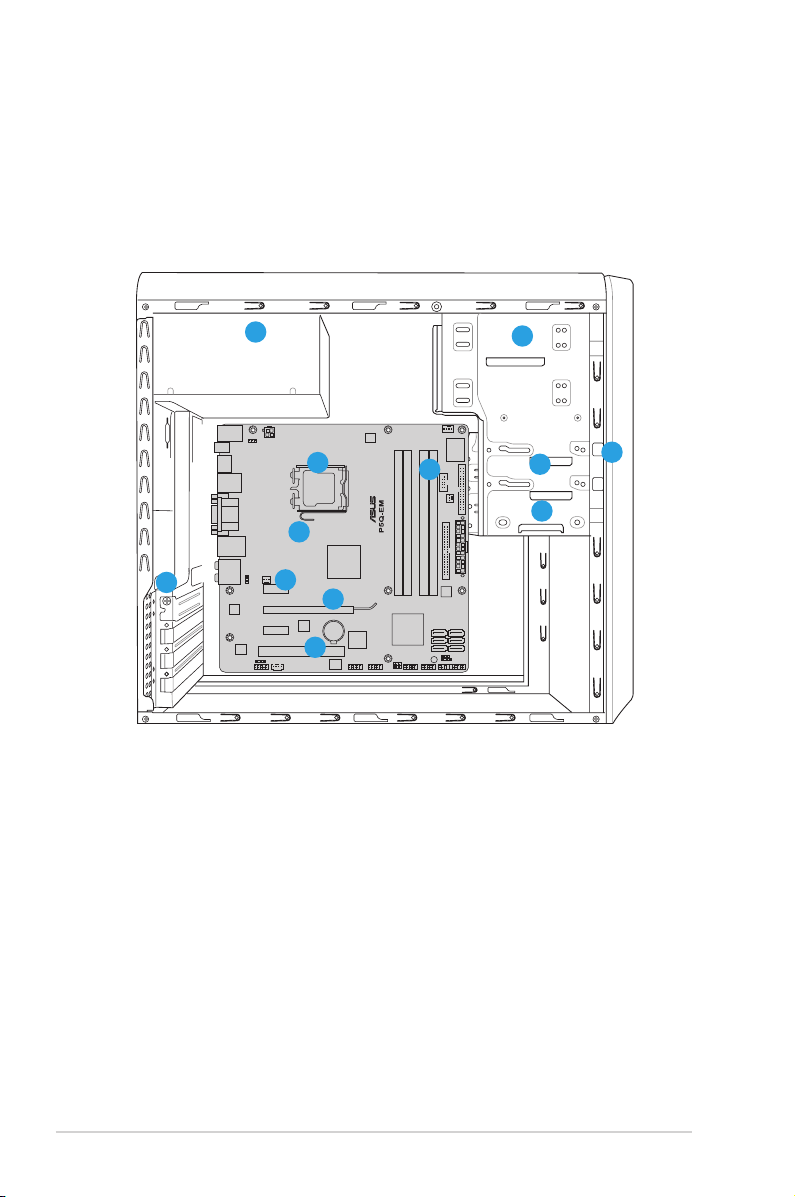
1.4 Internal components
2
1
3
5
4
9
6
7
12
8
10
11
The illustration below is the internal view of the system when you remove the top
cover and the power supply unit. The installed components are labeled for your
reference. Proceed to Chapter 2 for instructions on installing additional system
components.
1. Front panel cover
2. 5.25-inch optical drive bays
3. Floppy disk drive bay
4. Hard disk drive bay
5. Power supply unit
6. CPU socket
7. DIMM sockets
1-8 Chapter 1: System introduction
8. ASUS motherboard
9. PCI Express x16 slot
10. PCI Express x1 slot
11. PCI slots
12. Metal bracket lock
Page 19
Chapter 2
R
R
This chapter provides step-by-step
instructions on how to install
components in the system.
Basic installation
Page 20
2.1 Preparation
Before you proceed, make sure that you have all the components you plan to
install in the system.
Basic components to install
1. Central Processing Unit (CPU)
2. DDR2 Dual Inline Memory Module (DIMM)
3. Expansion card(s)
4. Hard disk drive
5. Optical drive
6. Floppy disk drive
Tool
Phillips (cross) screw driver
2.2 Before you proceed
Take note of the following precautions before you install components into the
system.
•
Use a grounded wrist strap or touch a safely grounded object or a metal
object, such as the power supply case, before handling components to
avoid damaging them due to static electricity.
•
Hold components by the edges to avoid touching the ICs on them.
•
Whenever you uninstall any component, place it on a grounded antistatic
pad or in the bag that came with the component.
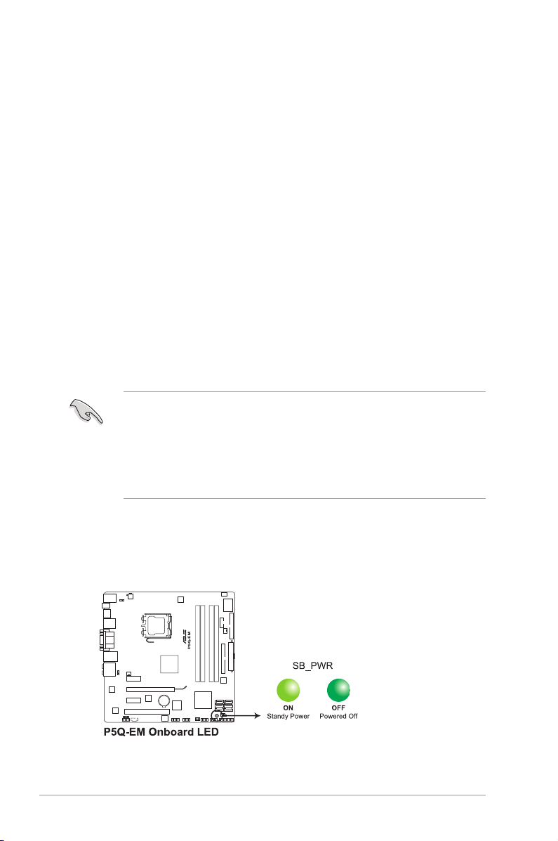
The motherboard comes with an onboard standby power LED. This LED lights
up to indicate that the system is ON, in sleep mode or in soft-off mode, and not
powered OFF. Unplug the power cable from the power outlet and make sure that
the standby power LED is OFF before installing any system component.
2-2 Chapter 2: Basic installation
Page 21
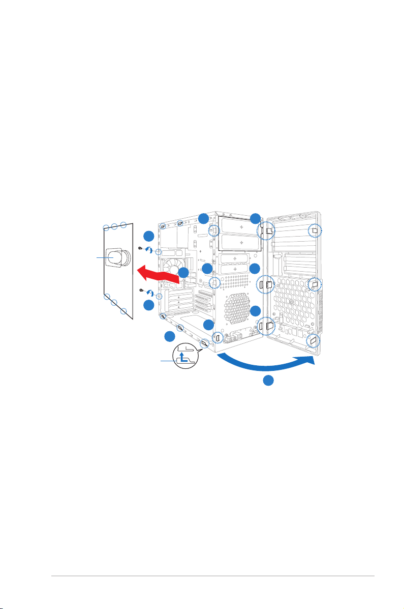
2.3 Removing the side cover and front panel assembly
1. Remove the cover screws on the rear panel.
2. Pull the side cover toward the rear panel until its hooks disengage from the
chassis tab holes. Set the side cover aside.
3. Locate the front panel assembly hooks, then lift them until they disengage
from the chassis.
4. Swing the front panel assembly to the right, until the hinge-like tabs on the
right side of the assembly are exposed.
5. Remove the front panel assembly, then set aside.
3 4
1
Air duct
3
2
4
Chassis tab holes
1
3
2
4
4
2-3ASUS V-Series P5G45
Page 22
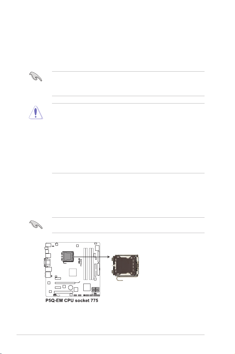
2.4 Central Processing Unit (CPU)
2.4.1 Overview
The motherboard comes with a surface mount LGA775 socket designed for the
Intel® Core™2 Quad / Intel® Core™2 Extreme / Core™2 Duo / Pentium® dual-core /
Celeon® dual-core/ Celeon® processors.
• Make sure that all power cables are unplugged before installing the CPU.
• Connect the chassis fan cable to the CHA_FAN1 connector to ensure
system stability.
•
Upon purchase of the motherboard, make sure that the PnP cap is on
the socket and the socket contacts are not bent. Contact your retailer
immediately if the PnP cap is missing, or if you see any damage to the PnP
cap/socket contacts/motherboard components. ASUS will shoulder the cost
of repair only if the damage is shipment/transit-related.
•
Keep the cap after installing the motherboard. ASUS will process Return
Merchandise Authorization (RMA) requests only if the motherboard comes
with the cap on the LGA775 socket.
• The product warranty does not cover damage to the socket contacts
resulting from incorrect CPU installation/removal, or misplacement/loss/
incorrect removal of the PnP cap.
2.4.2 Installing CPU
To install a CPU:
1. Locate the CPU socket on the motherboard.
Before installing the CPU, make sure that the socket box is facing towards you
and the load lever is on your left.
2-4 Chapter 2: Basic installation
Page 23
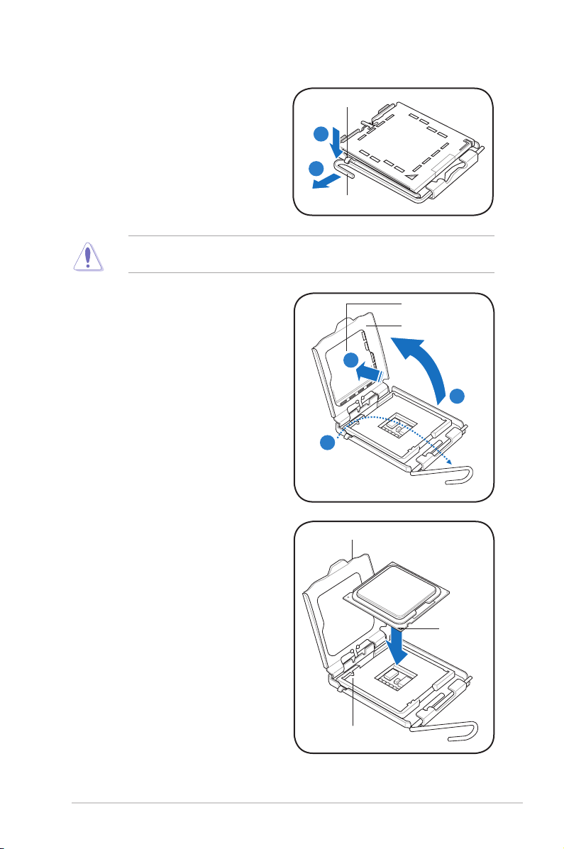
2. Press the load lever with your thumb
(A), then move it to the left (B) until it
is released from the retention tab.
To prevent damage to the socket pins, do not remove the PnP cap unless you
are installing a CPU.
Retention tab
A
B
Load lever
3. Lift the load lever in the direction of
the arrow to a 135º angle.
4. Lift the load plate with your thumb
and forenger to a 100º angle (4A),
then push the PnP cap from the
load plate window to remove (4B).
5. Position the CPU over the socket,
making sure that the gold triangle
is on the bottom-left corner of the
socket then t the socket alignment
key into the CPU notch.
PnP cap
Load plate
4B
4A
3
CPU notch
Gold
triangle
mark
Alignment key
2-5ASUS V-Series P5G45
Page 24
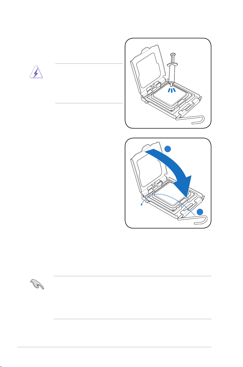
6. Apply Thermal Interface Material
on the CPU before closing the load
plate.
DO NOT eat the Thermal
Interface Material. If it gets
into your eyes or touches
your skin, make sure to wash
it off immediately, and seek
professional medical help.
7. Close the load plate (A), then push
the load lever (B) until it snaps into
the retention tab.
A
B
2.4.3 Installing the CPU fan and heatsink assembly
The Intel® Pentium® 4 LGA775 processor requires a specially designed heatsink
and fan assembly to ensure optimum thermal condition and performance.
• When you buy a boxed Intel® Pentium® 4 processor, the package
includes the CPU fan and heatsink assembly. If you buy a CPU separately,
make sure that you use only Intel®-certied multi-directional heatsink and
fan.
• Your Intel® Pentium® 4 LGA775 heatsink and fan assembly comes in a
push-pin design and requires no tool to install.
2-6 Chapter 2: Basic installation
Page 25
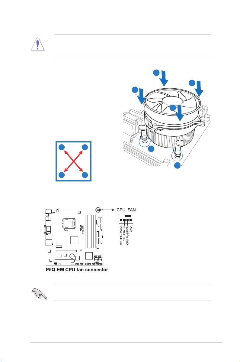
If you purchased a separate CPU heatsink and fan assembly, make sure that
the Thermal Interface Material is properly applied to the CPU heatsink or CPU
before you install the heatsink and fan assembly.
To install the CPU heatsink and fan:
1. Place the heatsink on top of the
installed CPU, making sure that the
B
A
B
four fasteners match the holes on
the motherboard.
A
2. Push down two fasteners at a time in
a diagonal sequence to secure the
heatsink and fan assembly in place.
A
B
B
1
1
A
3. When the fan and heatsink assembly is in place, connect the CPU fan cable
to the connector on the motherboard.
Do not forget to connect the CPU fan connector! Hardware monitoring errors
can occur if you fail to plug this connector.
2-7ASUS V-Series P5G45
Page 26

2.5 Installing a �IMM Installing a �IMM
2.5.1 Overview
The motherboard comes with four Double Data Rate 2 (DDR2) Dual Inline Memory
Modules (DIMM) sockets.
A DDR2 module has the same physical dimensions as a DDR DIMM but has a
240-pin footprint compared to the 184-pin DDR DIMM. DDR2 DIMMs are notched
differently to prevent installation on a DDR DIMM socket.
The gure illustrates the location of the DDR2 DIMM sockets:
Channel Sockets
Channel A DIMM_A1 and DIMM_A2
Channel B DIMM_B1 and DIMM_B2
2-8 Chapter 2: Basic installation
Page 27
2.5.2 Memorycongurations
You may install 512 MB, 1 GB, 2 GB, and 4 GB non-ECC, unbuffered, DDR2
DIMMs into the DIMM sockets.
• Due to chipset behavior, to obtain memory frequency higher than DDR2
800, you can manually adjust DRAM Frequency in BIOS settings. Refer to
5.4 Ai Tweaker menu for details.
• You may install varying memory sizes in Channel A and Channel B. The
system maps the total size of the lower-sized channel for the dual-channel
conguration. Any excess memory from the higher-sized channel is then
mapped for single-channel operation.
• It is recommended to install the memory modules from the yellow slots for
better overclocking capability.
• Always install DIMMs with the same CAS latency. For optimum
compatibility, it is recommended that you obtain memory modules from the
same vendor.
• When installing total memory of 4GB capacity or more, Windows® 32-bit
operation system may only recognize less than 3GB. Hence, a total
installed memory of less than 3 GB is recommended.
• This motherboard does not support memory modules made up of 256 Mb
chips.
• Due to chipset limitation, this motherboard can only support up to 16 GB
on the operating systems listed below. You may install a maximum of 4 GB
DIMMs on each slot.
64-bit
Windows® XP Professional x64 Edition
Windows® Vista x64 Edition
• The default memory operation frequency is dependent on its SPD. Under
the default state, some memory modules for overclocking may operate at a
lower frequency than the vendor-marked value. To operate at the vendormarked or at a higher frequency, see section 5.4 Ai Tweaker menu for
manual memory frequency adjustment.
• The memory modules may require a better cooling system to work stably
under full loading (4 DIMMs) or overclocking setting.
2-9ASUS V-Series P5G45
Page 28

P5Q-EMMotherboardQualiedVendorsLists(QVL)
DDR2-1066MHz capability
Vendor Part No. Size
A-DATA ADQYE1B16 2048MB DS Heat-Sink Package 5 •
Box P/N:CH.02GAF.C0KK2
Apacer
(78.0AG9S.9KF)
BoxP/N:CH.04GAF.F0KK2
Apacer
(78.AAGAL.9KF)
Box P/N:TWIN2X2048-8500C5D
CORSAIR
(CM2X1024-8500C5D)(EPP)
Box P/N:TWIN2X4096-
CORSAIR
8500C5DF
(CM2X2048-8500C5D)(EPP)
G.SKILL F2-8500CL5D-2GBPK 2048MB(Kit of 2) DS Heat-Sink Package 5-5-5-15 •
G.SKILL F2-8500CL5S-1GBPK 1024MB DS Heat-Sink Package 5-5-5-15 • • •
GEIL GB22GB8500C5DC 1024MB SS GL2L128M88BA25AB 5-5-5-15 • •
GEIL GE24GB1066C5QC 4096MB(Kit of 4) SS Heat-Sink Package 5-5-5-15 • • •
GEIL GB24GB8500C5DC 4096MB(Kit of 2) DS GL2L128M88BA25AB 5-5-5-15 • • •
GEIL GB24GB8500C5QC 4096MB(Kit of 4) DS GL2L128M88BA25AB 5-5-5-15 • •
GEIL GE24GB1066C5DC 4096MB(Kit of 2) DS Heat-Sink Package N/A •
GEIL GX24GB8500C5UDC 4096MB(Kit of 2) DS Heat-Sink Package 5-5-5-15 • • •
Hynix HYMP564U64FP8-G7 512MB SS HY5PS12821FFP-G7 7 •
Hynix HYMP 512U64FP8-G7 1024MB DS HY5PS12821FFP-G7 7 •
Kingston KHX8500D2/ 512 512MB SS Heat-Sink Package N/A • •
Kingston KHX8500D2K2/1G 1024MB(Kit of 2) SS Heat-Sink Package N/A • •
Kingston KVR1066D2N7/ 512 512MB SS E5108AJBG -1J-E N/A •
Kingston KVR1066D2N7/1G 1024MB DS E5108AJBG -1J-E N/A • •
MICRON MT8HTF12864AY-1GAE1 1024MB SS D9JKH 7 •
Box P/N:OCZ2N10662GK
OCZ
(OCZ2N10662GK)(EPP)
OCZ OCZ2RPR10664GK 4096MB(Kit of 2) DS Heat-Sink Package N/A •
Qimonda HYS64T64000EU-19F-C 512MB SS HYB18T 512800CF19F 6 •
Qimonda HYS64T128020EU-1.9-C 1024MB DS HYB18T 512800CF19 7 •
Transcend TX1066QLU-2GK 2048MB(Kit of 2) SS Heat-Sink Package 5 • • •
2048MB(Kit of 2) DS Heat-Sink Package 5-5-5-15 •
4096MB(Kit of 2) DS Heat-Sink Package 5-5-5-15 • •
1024MB DS Heat-Sink Package N/A •
4096MB(Kit of 2) DS Heat-Sink Package 5-5-5-15 •
2048MB(Kit of 2) DS Heat-Sink Package N/A • •
SS/
Chip No. CL
DS
DIMM support
A* B* C*
2-10 Chapter 2: Basic installation
Page 29

P5Q-EMMotherboardQualiedVendorsLists(QVL)
DDR2-800MHz capability
Vendor Part No. Size
A-DATA M2OAD6H3J4171Q1E52 2048MB DS AD20908A8A-25EG N/A • • •
Apacer 78.01GA0.9K5 1024MB SS AM4B5808CQJS8E N/A • • •
Apacer 78.91G9I.9K5 512MB SS AM4B5708JQJS8E N/A • •
Apacer 78.A1GA0.9K4 2048MB DS AM4B5808CQJS8E 5 • •
CORSAIR
CORSAIR
CORSAIR
CORSAIR CM2X1024-6400C4 1024MB DS Heat-Sink Package 4 •
Crucial BL12864AA804.16FD3 1024MB DS Heat-Sink Package 4 • • •
Crucial BL12864AA804.16FD 1024MB DS Heat-Sink Package 4 • •
Crucial BL12864AL804.16FD3 1024MB DS Heat-Sink Package 4 • • •
ELPIDA EBE10EE8ABFA-8E-E 1024MB SS E1108AB-8E-E(ECC) 5 • • •
G.SKILL F2-6400CL5D-1GBNQ 1024MB(Kit of 2) SS Heat-Sink Package 5-5-5-15 • •
G.SKILL F2-6400CL4D-2GBHK 1024MB DS Heat-Sink Package N/A • • •
G.SKILL F2-6400CL4D-2GBPK 1024MB DS Heat-Sink Package N/A • • •
G.SKILL F2-6400CL4D-4GBPK 4096MB(Kit of 2) DS Heat-Sink Package 4 • • •
G.SKILL F2-6400CL5D-2GBNQ 1024MB DS Heat-Sink Package N/A • •
G.SKILL F2-6400CL5D-4GBPQ 4096MB(Kit of 2) DS Heat-Sink Package 5 • •
G.SKILL F2-6400CL6D-4GBMQ 4096MB(Kit of 2) DS Heat-Sink Package 6 • •
G.SKILL F2-6400CL6D-8GBNQ 8192MB(Kit of 2) DS Heat-Sink Package 6-6-6-18 • • •
G.SKILL F2-6400PHU2-2GBNR 1024MB DS Heat-Sink Package N/A • • •
GEIL GB22GB6400C4DC 2048MB(Kit of 2) DS GL2L64M088BA30EB N/A • • •
GEIL GB22GB6400C5DC 2048MB(Kit of 2) DS GL2L64M088BA30EB 5-5-5-15 • • •
GEIL GB24GB6400C4DC 4096MB(Kit of 2) DS GL2L128M88BA25AB 4-4-4-12 • • •
GEIL GB24GB6400C4QC 4096MB(Kit of 4) DS GL2L64M088BA30EB N/A • • •
GEIL GB24GB6400C5DC 4096MB(Kit of 2) DS GL2L128M88BA25AB 5-5-5-15 • • •
GEIL GB24GB6400C5QC 4096MB(Kit of 2) DS GL2L64M088BA30EB N/A • • •
GEIL GB28GB6400C4QC 8192MB(Kit of 4) DS GL2L128M88BA25AB N/A • • •
GEIL GB28GB6400C5QC 8192MB(Kit of 4) DS GL2L128M88BA25AB N/A • • •
GEIL GE22GB800C4DC 2048MB(Kit of 2) DS Heat-Sink Package 4-4-4-12 • • •
GEIL GE22GB800C5DC 2048MB(Kit of 2) DS Heat-Sink Package 5-5-5-15 • • •
GEIL GE24GB800C4DC
Box P/N:TWIN2X4096-6400C5
(CM2X2048-6400C5)
BoxP/N:TWIN2X40966400C4DHX
(CM2X2048-6400C4DHX)
BoxP/N:TWIN2X40966400C5DHX
(CM2X2048-6400C5DHX)
4096MB(Kit of 2) DS Heat-Sink Package N/A • • •
4096MB(Kit of 2) DS Heat-Sink Package 4-4-4-12 • • •
4096MB(Kit of 2) DS Heat-Sink Package N/A • •
DDR2 800
2048MB
SS/
Chip No. CL
DS
DS Heat-Sink Package 4-4-4-12 • • •
DIMM support
A* B* C*
(continued on the next page)
2-11ASUS V-Series P5G45
Page 30

Vendor Part No. Size
GEIL GE24GB800C4QC 4096MB(Kit of 4) DS Heat-Sink Package N/A • • •
GEIL GE24GB800C5DC 2048MB DS Heat-Sink Package 5-5-5-15 • • •
GEIL GE24GB800C5QC 4096MB(Kit of 4) DS Heat-Sink Package 5-5-5-15 • • •
GEIL GE28GB800C4QC 2048MB DS Heat-Sink Package 4-4-4-12 • • •
GEIL GE28GB800C5QC 2048MB DS Heat-Sink Package 5-5-5-15 • • •
GEIL GX22GB6400C4USC 2048MB DS Heat-Sink Package 4-4-4-12 • • •
GEIL GX22GB6400DC 2048MB(Kit of 2) DS Heat-Sink Package 5-5-5-15 • • •
GEIL GX22GB6400LX 2048MB DS Heat-Sink Package 5-5-5-15 • • •
GEIL GX22GB6400UDC 2048MB(Kit of 2) DS Heat-Sink Package 4-4-4-12 • • •
GEIL GX24GB6400DC 4096MB(Kit of 2) DS Heat-Sink Package 5-5-5-15 • • •
Hynix HYMP564U64CP8-S5 512MB SS HY5PS12821CFP-S5 5-5-5 • • •
Hynix HYMP 512U64CP8-S5 1024MB DS HY5PS12821CFP-S5 5-5-5 • • •
KINGMAX KLDC28F-A8KI5 512MB SS KKA8FEIBF-HJK-25A N/A • • •
KINGMAX KLDD48F-ABKI5 1024MB DS KKA8FEIBF-HJK-25A N/A • • •
KINGMAX KLDE88F-B8KB5 2048MB DS KKB8FFBXF-CFA-25A N/A • • •
KINGSTON KHX6400D2/ 512 512MB SS Heat-Sink Package N/A • •
KINGSTON KHX6400D2ULK2/1G 1024MB(Kit of 2) SS Heat-Sink Package N/A •
KINGSTON KVR800D2N5/ 512 512MB SS E5108AJBG-8E-E N/A • •
KINGSTON KVR800D2N6/ 512 512MB SS E5108AJBG-8E-E 1.8 • •
KINGSTON KHX6400D2/2G 2048MB DS Heat-Sink Package N/A •
KINGSTON KHX6400D2LL/1G 1024MB DS Heat-Sink Package 4-4-4-12 • • •
KINGSTON KVR800D2N5/1G 1024MB DS E5108AJBG-8E-E N/A • • •
KINGSTON KVR800D2N5/1G 1024MB DS E5108AJBG-8E-E N/A • • •
KINGSTON KVR800D2N5/1G 1024MB DS V59C1 512804QBF25 N/A • • •
KINGSTON KVR800D2N5/2G 2048MB DS E1108ACBG-8E-E N/A • •
KINGSTON KVR800D2N6/1G 1024MB DS E5108AJBG-8E-E 1.8 • • •
KINGSTON N/A 4096MB DS E2108ABSE-8G-E N/A •
NANYA NT 512T64U880BY-25C 512MB SS NT5TU64M8BE-25C 5 • • •
NANYA NT1GT64U8HB0BY-25C 1024MB DS NT5TU64M8BE-25C 5 • • •
NANYA NT1GT64U8HCOBY-25D 1024MB DS NT5TU64M8CE-25D N/A • • •
NANYA NT2GT64U8HC0BY-AC 2048MB DS NT5TU128M8CE-AC 5 • •
OCZ OCZ2FX800C32GK 1024MB DS Heat-Sink Package N/A • • •
OCZ OCZ2G8002GK 1024MB DS Heat-Sink Package N/A •
OCZ OCZ2P8004GK 4096MB(Kit of 2) DS Heat-Sink Package 5-4-4 • • •
OCZ OCZ2P800R22GK 2048MB(Kit of 2) DS Heat-Sink Package 4 • • •
OCZ OCZ2T8002GK 1024MB DS Heat-Sink Package N/A • •
SS/
Chip No. CL
DS
DIMM support
A* B* C*
(continued on the next page)
2-12 Chapter 2: Basic installation
Page 31

Vendor Part No. Size
PSC AL8E8F73C-8E1 2048MB DS 5 • • •
Qimonda HYS64T256020EU-2.5-C2 2048MB DS HYB18T1G800C2F-2.5 6 • • •
Qimonda HYS64T256020EU-25F-C2 2048MB DS HYB18T1G800C2F-25F 5 • •
SAMSUNG M378T2863QZS-CF7 1024MB SS K4T1G084QQ 6 • • •
SAMSUNG M378T6553GZS-CF7 512MB SS K4T51083QG 6 • • •
SAMSUNG M391T2863QZ3-CF7 1024MB SS K4T1G084QQ(ECC) 6 • • •
SAMSUNG M378T2953GZ3-CF7 1024MB DS K4T51083QG 6 • • •
SAMSUNG M378T5263AZ3-CF7 4096MB DS K4T2G084QA-HCF7 6 • • •
SAMSUNG M378T5663QZ3-CF7 2048MB DS K4T1G084QQ(ECC) 6 • • •
SAMSUNG M391T5663QZ3-CF7 2048MB DS K4T1G084QQ 6 • • •
Super Talent T800UA12C4 512MB SS Heat-Sink Package N/A • • •
Super Talent T800UB1GC4 1024MB DS Heat-Sink Package N/A • • •
Transcend JM800QLU-1G 1024MB SS TQ243ECF8 5 • • •
Transcend JM800QLJ-1G 1024MB DS TQ123PJF8 5 • •
Transcend JM800QLU-2G 2048MB DS TQ243PCF8 5 • • •
SS/
Chip No. CL
DS
DIMM support
A* B* C*
P5Q-EMMotherboardQualiedVendorsLists(QVL)
DDR2-667MHz capability
Vendor Part No. Size
Apacer 78.01G9O.9K5 1024MB SS AM4B5808CQJS7E N/A • • •
Apacer 78.91G92.9K5 512MB SS AM4B5708JQJS7E N/A • • •
Apacer 78.A1G9O.9K4 2048MB DS AM4B5808CQJS7E N/A • • •
CORSAIR VS 512MB667D2 512MB SS 64M8CFEG N/A •
CORSAIR VS1GB667D2 1024MB DS 64M8CFEG N/A • • •
crucial BL6464AA663.8FD 512MB SS Heat-Sink Package 3 • •
crucial BL12864AA663.16FD2 1024MB DS Heat-Sink Package 3 • • •
crucial BL12864AA663.16FD 1024MB DS Heat-Sink Package 3 • • •
crucial BL12864AL664.16FD 1024MB DS Heat-Sink Package 3 •
ELPIDA EBE51UD8AEFA-6E-E 512MB SS E5108AE-6E-E 5 • •
G.SKILL F2-5300CL5D-4GBMQ 4096MB(Kit of 2) DS Heat-Sink Package 5-5-5-15 • • •
G.SKILL F2-5400PHU2-2GBNT 2048MB(Kit of 2) DS D264M8GCF 5-5-5-15 • • •
GEIL GX21GB5300SX 1024MB DS Heat-Sink Package 3-4-4-8 •
GEIL GX22GB5300LX 2048MB DS Heat-Sink Package 5-5-5-15 • • •
SS/
Chip No. CL
DS
DIMM support
A* B* C*
(continued on the next page)
2-13ASUS V-Series P5G45
Page 32

Vendor Part No. Size
GEIL GX24GB5300LDC 4096MB(Kit of 2) DS Heat-Sink Package 5-5-5-15 • • •
Hynix HYMP112U64CP8-Y5 1024MB SS HY5PS1G831CFP-Y5 5 • • •
Hynix HYMP 512U64CP8-Y5 1024MB DS HY5PS12821CFP-Y5 5 •
KINGSTON KVR667D2N5/ 512 512MB SS D6408TEBGGL3U 5 • •
KINGSTON KVR667D2E5/1G 1024MB DS E5108AGBG-6E-E(ECC) N/A • •
KINGSTON KVR667D2E5/2G 2048MB DS D9HNL(ECC) N/A • • •
KINGSTON KVR667D2N5/1G 1024MB DS E5108AGBG-6E-E N/A • • •
KINGSTON KVR667D2N5/1G 1024MB DS E5108AJBG-8E-E N/A • • •
KINGSTON KVR667D2N5/1G 1024MB DS HY5PS12821CFP-Y5 N/A • • •
KINGSTON KVR667D2N5/2G 2048MB DS E1108AB-6E-E N/A • •
KINGSTON KVR667D2N5/2G 2048MB DS HY5PS1G831CFP-Y5 N/A • • •
NANYA NT 512T64U88B0BY-3C 512MB SS NT5TU64M8BE-3C 5 • •
NANYA NT2GT64U8HB0JY-3C 2048MB DS NT5TU128M8BJ-3C 5 • • •
PSC AL7E8E63J-6E1 1024MB DS A3R12E3JFF719A9T02 5 • • •
Qimonda
SAMSUNG M378T6553EZS-CE6 512MB SS K4T51083QE 5 • • •
SAMSUNG M378T2953EZ3-CE6 1024MB DS K4T51083QE 5 • • •
SAMSUNG M378T5263AZ3-CE6 4096MB DS K4T2G084QA-HCE6 5 • • •
Super Talent T6UA 512C5 512MB SS Heat-Sink Package 5 • • •
Super Talent T6UB1GC5 1024MB DS Heat-Sink Package 5 • • •
Transcend JM667QLU-1G 1024MB SS TQ243ECF8 5 • •
Transcend JM667QLU-2G 2048MB DS TQ243ECF8 5 • • •
TwinMOS 8D-23JK5M2ETP 512MB SS TMM6208G8M30C 5 • •
HYS64T256020EU3S-C2
2048MB DS HYB18T1GB00C2F-3S 555-12 • • •
SS/
Chip No. CL
DS
DIMM support
A* B* C*
SS - Single-sided / DS - Double-sided
DIMM support:
• A*: Supports one module inserted in any slot as Single-channel
memory conguration.
• B*: Supports one pair of modules inserted into either the yellow slots
or the black slots as one pair of Dual-channel memory conguration.
• C*: Supports four modules inserted into both the yellow and black slots
as two pairs of Dual-channel memory conguration.
Visit the ASUS website for the latest DDR2-1066/800/667MHz QVL.
Visit the ASUS website for the latest DDR2-1066/800/667MHz QVL.
2-14 Chapter 2: Basic installation
Page 33

2.5.3 Installing a DDR2 DIMM
Make sure to unplug the power supply before adding or removing DIMMs or
other system components. Failure to do so may cause severe damage to both
the motherboard and the components.
1. Unlock a DDR2 DIMM socket
by pressing the retaining clips
outward.
2. Align a DIMM on the socket
such that the notch on the DIMM
matches the break on the socket.
Unlocked retaining clip
A DDR2 DIMM is keyed with a notch so that it ts in only one direction. DO
NOT force a DIMM into a socket to avoid damaging the DIMM.
2
DDR2 DIMM notch
1
1
3. Firmly insert the DIMM into the
socket until the retaining clips snap
back in place and the DIMM is
properly seated.
Locked Retaining Clip
2.5.4 Removing a DDR2 DIMM
Follow these steps to remove a DIMM.
1. Simultaneously press the
retaining clips outward to unlock
the DIMM.
Support the DIMM lightly with your ngers when pressing the retaining clips.
The DIMM might get damaged when it ips out with extra force.
2. Remove the DIMM from the socket.
3
2
1
1
DDR2 DIMM notch
2-15ASUS V-Series P5G45
Page 34

2.6 Expansion slots
In the future, you may need to install expansion cards. The following sub-sections
describe the slots and the expansion cards that they support.
Make sure to unplug the power cord before adding or removing expansion
cards. Failure to do so may cause you physical injury and damage motherboard
components.
2.6.1 Installing an expansion card
To install an expansion card:
1. Before installing the expansion card, read the documentation that came with
it and make the necessary hardware settings for the card.
2. Remove the system unit cover (if your motherboard is already installed in a
chassis).
3. Remove the bracket opposite the slot that you intend to use. Keep the screw
for later use.
4. Align the card connector with the slot and press rmly until the card is
completely seated on the slot.
5. Secure the card to the chassis with the screw you removed earlier.
6. Replace the system cover.
2.6.2 Conguringanexpansion card
After installing the expansion card, congure it by adjusting the software settings.
1. Turn on the system and change the necessary BIOS settings, if any. See
Chapter 5 for information on BIOS setup.
2. Assign an IRQ to the card. Refer to the tables on the next page.
3. Install the software drivers for the expansion card.
When using PCI cards on shared slots, ensure that the drivers support “Share
IRQ” or that the cards do not need IRQ assignments. Otherwise, conicts will
arise between the two PCI groups, making the system unstable and the card
inoperable.
2-16 Chapter 2: Basic installation
Page 35

Interrupt assignments
IRQ Priority Standard function
0 1 System timer
1 2 Keyboard controller
2
3 11 IRQ holder for PCI steering*
4 12 Communications port (COM1)*
5
6 14 Floppy disk controller
7 15 IRQ holder for PCI steering*
8 3 System CMOS/Real Time Clock
9 4 IRQ holder for PCI steering*
10 5 IRQ holder for PCI steering*
11 6 IRQ holder for PCI steering*
12 7 PS/2 compatible mouse port*
13 8 Numeric data processor
14 9 IRQ holder for PCI steering*
15 10 IRQ holder for PCI steering*
– Re-direct to IRQ#9
13 IRQ holder for PCI steering*
* These IRQs are usually available for PCI devices.
IRQ assignments for this motherboard
A B C D E F G H
1394 (FW3227) – – – shared – – – –
LAN (8111C) – shared – – – – – –
Marvell 6102 shared – – – – – – –
PCIEX16_1 shared – – – – – – –
PCIEX1_1 shared – – – – – – –
PCIEX1_2 – shared – – – – – –
PCI1 shared – – – – – – –
USB controller 1 – – – – – – – used
USB controller 2 – – – shared – – – –
USB controller 3 – – shared – – – – –
USB controller 4 shared – – – – – – –
USB controller 5 shared – – – – – –
USB controller 6 – – – – – used – –
USB 2.0 controller 1 – – – – – – – shared
USB 2.0 controller 2 – – shared – – – – –
SATA controller 1 – – shared – – – – –
SATA controller 2 – – – shared – – – –
2-17ASUS V-Series P5G45
Page 36

2.6.3 PCI slots
The PCI slots support cards such as
a LAN card, SCSI card, USB card,
and other cards that comply with PCI
specications. The gure shows a LAN
card installed on a PCI slot.
2.6.4 PCI Express x1 slot
This motherboard supports PCI Express
x1 network cards, SCSI cards and
other cards that comply with the PCI
Express specications. The gure shows
a network card installed on the PCI
Express x1 slot.
2.6.5 PCI Express x16 slot
This motherboard supports PCI Express
x16 graphic cards that comply with the
PCI Express specications. The gure
shows a graphics card installed on the
PCI Express x16 slot.
2-18 Chapter 2: Basic installation
Page 37

2.7 Installing an optical drive
4
4
3
Refer to the instructions in this section if you wish to install a new optical drive.
Follow these steps to install an optical drive:
1. Place the chassis upright.
2. Remove the drive slot metal plate cover.
3. Insert the optical drive into the upper 5.25-inch drive bay and carefully push
the optical drive into the bay until its screw holes align with the holes on the
bay as shown.
4. Secure the optical drive with two screws on both sides of the bay.
5. Connect a power cable from
the power supply to the power
connector at the back of the optical
drive.
6. Connect one end of the IDE ribbon
cable to the IDE interface at the
back of the optical drive, matching
the red stripe on the cable with Pin
1 on the IDE interface.
IDE ribbon cable
Power cable
2-19ASUS V-Series P5G45
Page 38

7. Connect the other end of the IDE ribbon cable to the secondary IDE
connector (labeled SEC_IDE) on the motherboard. See page 4-7 for the
location of this connector.
8. Remove the dummy drive slot cover from the front panel.
9. Replace the front panel.
2.8 Installing a hard disk drive
To install a Serial ATA hard disk drive:
1. Carefully place the hard disk into the the lowest 3.5-inch drive slot (without
the metal plate cover).
2. Fasten the screws to secure the hard disk to the drive slot.
the lowest 3.5-inch
drive slot without
the metal plate
cover
If you do not need to install the optional card reader into your system, you can
install the HDD in the one of the 3.5-inch external bay (with the metal plate
cover).
3. Connect one end of the Serial ATA cable to the SATA connector at the back
of the drive, then connect the other end to a Serial ATA connector on the
motherboard. See page 4-6 for the location of the Serial ATA connectors.
2-20 Chapter 2: Basic installation
Page 39

4. Connect a 15-pin Serial ATA power plug from the power supply unit to the
15-pin power connector at the back of the drive.
- OR -
Connect a 4-pin (female) power plug from the power supply unit to the 4-pin
(male) power connector at the back of the drive.
Serial ATA power
cable
If your Serial ATA HDD has both 4-pin and 15-pin connectors at the back,
use either the 15-pin SATA power adapter plug OR the legacy 4-pin power
connector. DO NOT use both to prevent damage to components and to keep
the system from becoming unstable.
Serial ATA cable
To install an IDE hard disk drive:
1. Follow steps 1-2 of the previous section.
2. Connect the blue interface of the IDE ribbon cable to the primary IDE
connector (blue connector labeled PRI_IDE) on the motherboard. See page
4-7 for the location of the connector.
IDE ribbon cable
Power cable
2-21ASUS V-Series P5G45
Page 40

• If you will install only one hard disk drive, make sure to congure your hard
disk drive as Master device before connecting the IDE cable and power
plug. Refer to the HDD documentation on how to set the drive as a Master
device.
• If you will install two IDE hard disk drives, congure the other device as
Slave.
3. Connect the gray interface of the IDE ribbon cable to the IDE connector on
the drive.
4. If you install two IDE hard disk drives, connect the black interface of the IDE
ribbon cable to the IDE connector on the second (Slave) IDE hard disk drive.
5. Connect a 4-pin power plug from the power supply unit to the power
connector at the back of the drive(s).
2.9 Installing the card reader
An optional card reader module (see the gure below) is available with the system.
If you want to install the card reader into your system, follow the steps on the next
page.
Note: the card reader is optional and users need to purchase separately.
2-22 Chapter 2: Basic installation
Page 41

To install the card reader module:
1. Remove the drive slot metal plate cover.
2. Carefully insert the card reader module into the 3.5-inch bay until the screw
holes align with the holes on the bay.
3. Secure the card reader module with two screws on both sides.
remove the metal
plate cover and
install the card
reader module here
4. Connect the USB cable of the card reader to the USB connector on the
motherboard.
2-23ASUS V-Series P5G45
Page 42

2.10 Installingaoppydiskdrive
3
3
2
3
The system comes with one 3.25-inch drive bay for a oppy disk drive.
To install a oppy disk drive:
1. Remove the drive slot metal plate cover.
remove the metal
plate cover and
install the card
reader module here
2. Carefully insert the oppy disk drive into the oppy drive bay until the screw
holes align with the holes on the bay.
3. Secure the oppy disk drive with two screws on both sides.
4. Connect the oppy disk drive signal cable to the signal connector at the back
of the drive.
Power cable
Floppy ribbon cable
5. Connect the other end of the signal cable to the oppy disk drive connector
on the motherboard. See page 4-6 for the location of the oppy disk drive
connector.
6. Connect a 4-pin power cable from the power supply unit to the power connector
at the back of the oppy disk drive.
2-24 Chapter 2: Basic installation
Page 43

2.11 Re-connecting cables
I
You may have disconnected some cables when you were installing components.
You must re-connect these cables before you replace the chassis cover.
LED cables
Reset button
HDD LED
Power Switch
Power LED
Connect the reset button, power switch, power LED, and HDD LED cables to their
respective leads in the system panel connector on the motherboard.
2-25ASUS V-Series P5G45
Page 44

2.12 Reinstalling the cover
If you installed an optical and/or oppy disk drive, remove the bay cover(s) on the
front panel assembly before reinstalling it to the chassis. To do this:
1. Locate the bay cover locks.
2. Press the locks outward to release
the bay cover.
3. Push the bay cover inward, then set
it aside.
4. Follow the same instructions to
remove the 3.5” drive bay cover.
To reinstall the front panel assembly and side cover:
1. Insert the front panel assembly hinge-like tabs to the holes on the right side
of the chassis.
2. Swing the front panel assembly to the left, then insert the hooks to the
chassis until the front panel assembly ts in place.
3. Insert the six side cover hooks into the chassis tab holes .
4. Push the side cover to the direction of the front panel until it ts in place.
5. Secure the cover with two screws you removed earlier.
If the air duct interferes with the CPU fan, adjust the air duct accordingly.
2
5
4
5
Air duct
3
Chassis tab holes
2-26 Chapter 2: Basic installation
2
2
1
1
1
2
Page 45

Chapter 3
R
R
This chapter helps you power up the
system and install drivers and utilities
from the support DVD.
Starting up
Page 46

3.1 Installing an operating system
R
The barebone system supports Windows® XP/Vista operating systems (OS).
Always install the latest OS version and corresponding updates so you can
maximize the features of your hardware.
Because motherboard settings and hardware options vary, use the setup
procedures presented in this chapter for general reference only. Refer to your
OS documentation for more information.
• Windows XP OS setup cannot recognize Serial ATA hard drives without the
necessary drivers. Use the bundled oppy disk when installing Windows XP
OS to a Serial ATA hard drive.
• From the Windows XP setup screen, press F6 when prompted then follow
succeeding screen instructions to install the SATA drivers.
3.2 Powering up
Press the system power button ( ) to enter the OS.
Press to turn ON the system
3.3 Support �V� information
The support DVD that came with the system contains useful software and several
utility drivers that enhance the system features.
•
Screen display and driver options may not be the same for different
operating system versions.
•
The contents of the support DVD are subject to change at any time without
notice. Visit the ASUS website for updates.
3-2 Chapter 3: Starting up
Page 47

3.3.1 Running the support DVD
To begin using the support DVD, place the DVD in your optical drive. The DVD
automatically displays the Drivers menu if Autorun is enabled in your computer.
Click an icon to
display support
DVD/motherboard
information
Click an item to install
If Autorun is NOT enabled in your computer, browse the contents of the support
DVD to locate the le ASSETUP.EXE from the BIN folder. Double-click the
ASSETUP.EXE to run the DVD.
ASUS InstAll-Installation Wizard for Anti-Virus and Drivers Utility
Launches the ASUS InstAll driver installation wizard.
Norton Internet Security 2008
Installs the Norton Internet Security 2008.
Intel Chipset Inf Update Program
Installs the Intel® chipset Inf update program.
Realtek Audio Driver
Installs the Realtek® ALC1200 audio driver and application.
Intel Graphics Accelerator Driver
Installs the Intel® Graphics accerlerator driver.
Realtek RTL8111B/C LAN Driver
Installs the Realtek® RTL8111B/C LAN Driver.
ASUS EPU-4 Engine
Installs the ASUS EPU-4 Engine.
3-3ASUS V-Series P5G45
Page 48

USB 2.0 Driver
Installs USB 2.0 driver.
3.3.2 Utilities menu
The Utilities menu shows the applications and other software that the motherboard
supports.
ASUS InstAll-Installation Wizard for Utilities
Installs all of the utilities through the Installation Wizard.
ASUS Update
Allows you to download the latest version of the BIOS from the ASUS website.
Before using the ASUS Update, make sure that you have an Internet connection
so you can connect to the ASUS website.
ASUS PC Probe II
This smart utility monitors the fan speed, CPU temperature, and system voltages,
and alerts you of any detected problems. This utility helps you keep your computer
in healthy operating condition.
ASUS AI Suite
The ASUS AI Suite is an innovative application to do overclocking, fan control,
power saving and quiet therman control.
ASUS Express Gate Installer
Installs the ASUS Express Gate Installer.
3-4 Chapter 3: Starting up
Page 49

Adobe Acrobat Reader 8
Installs the Adobe® Acrobat® Reader that allows you to open, view, and print
documents in Portable Document Format (PDF).
Microsoft DirectX 9.0c
Installs the Microsoft® DirectX 9.0c driver. The Microsoft DirectX® 9.0c is a
multimedia technology that enhances computer graphics and sound. DirectX®
improves the multimedia features of you computer so you can enjoy watching
TV and movies, capturing videos, or playing games in your computer. Visit the
Microsoft website (www.microsoft.com) for updates.
Ulead Burn. Now
Installs the Ulead Burn. Now application for Audio DVD,CD and data disc creation.
Corel MediaOne Starter
Installs the Corel MediaOne Starter application to easily manage, edit share and
protect your multimedia data.
CyberLink PowerBackup
Installs CyberLink PowerBackup to back up and restore your data easily.
You can also install the following utilities from the ASUS Superb Software
Library DVD.
Ulead Photolmpact 12 SE
Installs the Photolmpact image editing software.
3-5ASUS V-Series P5G45
Page 50

WinZip 11
Installs the Winzip utility for easy le-compression and protection.
Norton Internet Security 2008
Installs the Norton Internet Security 2008.
ASUS Screen Saver
Installs the ASUS Screen saver.
3.3.3 Manual menu
The Manual menu contains a list of supplementary user manuals. Click an item to
open the folder of the user manual.
Most user manual les are in Portable Document Format (PDF). Install the
Adobe® Acrobat® Reader from the ASUS Superb Software Library DVD before
opening a user manual le.
ASUS Motherboard Installation Guide
Allows you to open the ASUS Motherboard Installation Guide.
NIS 2008 Subscription Renewal Guide
Allows you to open the NIS 2008 Subscription Renewal Guide.
Intel® Matrix Storage Manager User’s Manual
Allows you to open the Intel® Matrix storage manager user’s manual.
3-6 Chapter 3: Starting up
Page 51

3.3.4 Make Disk menu
The Make Disk menu allows you to make a RAID/AHCI driver disk.
Intel® ICH 10R 32/64bit RAID/ACHI Driver Disk
Allows you to create Intel ICH 10R 32/64bit RAID/ACHI driver disk.
3.3.5 ASUS Contact information
Click the Contact tab to display the ASUS contact information. You can also nd
this information on the inside front cover of this user guide.
3-7ASUS V-Series P5G45
Page 52

3.3.6 Other information
The icons on the top right corner of the screen give additional information on the
motherboard and the contents of the support DVD. Click an icon to display the
specied information.
Motherboard Info
Displays the general specications of the motherboard.
Browse this DVD
Displays the support DVD contents in graphical format.
3-8 Chapter 3: Starting up
Page 53

Technical support Form
Displays the ASUS Technical Support Request Form that you have to ll out when
requesting technical support.
Filelist
Displays the contents of the support DVD and a brief description of each in text
format.
3-9ASUS V-Series P5G45
Page 54

3.4 Software information
Most of the applications in the support DVD have wizards that will conveniently
guide you through the installation. View the online help or readme le that came
with the software for more information.
ASUS PC Probe II
PC Probe II is a utility that monitors the computer’s vital components and alerts
you of any problem with these components. PC Probe II senses fan rotations, CPU
temperature, and system voltages, among others. PC Probe II is software-based,
allowing you to start monitoring your computer the moment you turn it on. With
this utility, you are assured that your computer is always at a healthy operating
condition.
Installing PC Probe II
To install PC Probe II on your computer:
1. Place the support DVD to the optical drive. The Drivers installation tab
appears if your computer has an enabled Autorun feature.
If Autorun is not enabled in your computer, browse the contents of the support
CD to locate the setup.exe le from the ASUS PC Probe II folder. Double-click
the setup.exe le to start installation.
2. Click the Utilities tab, then click ASUS PC Probe II.
3. Follow the screen instructions to complete installation.
Launching PC Probe II
You can launch the PC Probe II right after installation or anytime from the
Windows® desktop.
To launch the PC Probe II from the Windows® desktop, click Start > All Programs
> ASUS > PC Probe II. The PC Probe
II main window appears.
After launching the application, the PC
Probe II icon appears in the Windows®
taskbar. Click this icon to close or
restore the application.
Using PC Probe II
Main window
The PC Probe II main window allows you to view the current status of your system
and change the utility conguration. By default, the main window displays the
Preference section. You can close or restore the Preference section by clicking on
the triangle on the main window right handle.
3-10 Chapter 3: Starting up
Click to close the
Preference panel
Page 55

Button Function
Opens the Conguration window
Opens the Report window
Opens the Desktop Management Interface window
Opens the Peripheral Component Interconnect window
Opens the Windows Management Instrumentation window
Opens the hard disk drive, memory, CPU usage window
Shows/Hides the Preference section
Minimizes the application
Closes the application
Sensor alert
When a system sensor detects a problem, the main window right handle turns red,
as the illustrations below show.
When displayed, the monitor panel for that sensor also turns red. Refer to the
Monitor panels section for details.
Preferences
You can customize the application using the
Preference section in the main window. Click
the box before each preference to activate or
deactivate.
3-11ASUS V-Series P5G45
Page 56

Hardware monitor panels
The hardware monitor panels display the current value of a system sensor such as
fan rotation, CPU temperature, and voltages.
The hardware monitor panels come in two display modes: hexagonal (large) and
rectangular (small). When you check the Enable Monitoring Panel option from
the Preference section, the monitor panels appear on your computer’s desktop.
Small display
Large display
Changing the monitor panels position
To change the position of the monitor panels on the desktop, click
the arrow down button of the Scheme options, then select another
position from the list box. Click OK when nished.
Moving the monitor panels
All monitor panels move together using a magnetic effect. If you want
to detach a monitor panel from the group, click
the horseshoe magnet icon. You can now move
or reposition the panel independently.
Adjusting the sensor threshold value
You can adjust the sensor threshold value in
the monitor panel by clicking the arrow buttons. You can also adjust the threshold
values using the Cong window.
You cannot adjust the sensor threshold
values in a small monitoring panel.
Click to
increase value
Click to
decrease
value
3-12 Chapter 3: Starting up
Page 57

Monitoring sensor alert
The monitor panel turns red when a component value exceeds or is lower than the
threshold value. Refer to the illustrations below.
Small display
Large display
WMI browser
Click to display the
WMI (Windows Management
Instrumentation) browser. This
browser displays various Windows®
management information. Click an
item from the left panel to display on
the right panel. Click the plus sign (+)
before WMI Information to display the
available information.
You can enlarge or reduce the browser size by dragging the bottom right corner
of the browser.
DMI browser
Click to display the DMI
(Desktop Management Interface)
browser. This browser displays various
desktop and system information.
Click the plus sign (+) before DMI
Information to display the available
information.
3-13ASUS V-Series P5G45
Page 58

PCI browser
Click to display the PCI
(Peripheral Component Interconnect)
browser. This browser provides
information on the PCI devices
installed on your system. Click the plus
sign (+) before the PCI Information
item to display available information.
Usage
The Usage browser displays real-time information on the CPU, hard disk drive
space, and memory usage. Click to display the Usage browser.
CPU usage
The CPU tab displays real-time CPU
usage in line graph representation.
If the CPU has an enabled HyperThreading, two separate line graphs
display the operation of the two logical
processors.
Hard disk drive space usage
The Hard Disk tab displays the used
and available hard disk drive space.
The left panel of the tab lists all logical
drives. Click a hard disk drive to display
the information on the right panel. The
pie chart at the bottom of the window
represents the used (blue) and the
available HDD space.
3-14 Chapter 3: Starting up
Page 59

Memory usage
The Memory tab shows both used
and available physical memory. The
pie chart at the bottom of the window
represents the used (blue) and the
available physical memory.
ConguringPCProbeII
Click to view and adjust the sensor threshold values.
The Cong window has two tabs: Sensor/Threshold and Preference. The
Sensor/Threshold tab enables you to activate the sensors or to adjust the sensor
threshold values. The Preference tab allows you to customize sensor alerts,
change temperature scale, or enable the Q-Fan feature.
Loads the default
threshold values for
each sensor
Applies your
changes
Cancels or
ignores your
changes
Loads your saved
conguration
Saves your
conguration
3-15ASUS V-Series P5G45
Page 60

3-16 Chapter 3: Starting up
Page 61

Chapter 4
R
R
This chapter gives information about
he motherboard that comes with the
system. This chapter includes the
motherboard layout, jumper settings,
and connector locations.
Motherboard introductiomn
Page 62

4.1 Introduction
The Vintage V-Series P5G45 barebone system comes with an ASUS motherboard.
This chapter provides technical information about the motherboard for future
upgrades or system reconguration.
4.2 Motherboard layout
4-2 Chapter 4: Motherboard info
Page 63

4.3 Jumpers
1. Clear RTC RAM (CLRTC)
This jumper allows you to clear the Real Time Clock (RTC) RAM in
CMOS. You can clear the CMOS memory of date, time, and system setup
parameters by erasing the CMOS RTC RAM data. The onboard button
cell battery powers the RAM data in CMOS, which include system setup
information such as system passwords.
To erase the RTC RAM:
1. Turn OFF the computer and unplug the power cord.
2. Remove the onboard battery.
3. Move the jumper cap from pins 1-2 (default) to pins 2-3. Keep the cap on pins
2-3 for about 5~10 seconds, then move the cap back to pins 1-2.
4. Re-install the battery.
5. Plug the power cord and turn ON the computer.
6. Hold down the <Del> key during the boot process and enter BIOS setup to
re-enter data.
Except when clearing the RTC RAM, never remove the cap on CLRTC jumper
default position. Removing the cap will cause system boot failure!
Except when clearing the RTC RAM, never remove the cap on CLRTC jumper
default position. Removing the cap will cause system boot failure!
4-3ASUS V-Series P5G45
Page 64

• If the steps above do not help, remove the onboard battery and move
the jumper again to clear the CMOS RTC RAM data. After the CMOS
clearance, reinstall the battery.
• Yo u do no t n ee d t o cle ar th e RTC when the sy ste m han gs du e to
overclocking. For system failure due to overclocking, use the C.P.R. (CPU
Parameter Recall) feature. Shut down and reboot the system so the BIOS
can automatically reset parameter settings to default values.
• Due to the chipset behavior, AC power off is required to enable C.P.R.
function. You must turn off and on the power supply or unplug and plug the
power cord before rebooting the system.
2. USB device wake-up (3-pin USBPW1-4; USB7-10; USB1112)
Set these jumpers to +5V to wake up the computer from S1 sleep mode
(CPU stopped, DRAM refreshed, system running in low power mode) using
the connected USB devices. Set to +5VSB to wake up from S3 and S4 sleep
modes (no power to CPU, DRAM in slow refresh, power supply in reduced
power mode).
The USBPW1-4 jumper is for the rear USB ports. The USBPW7-10 and
USBPW1112 jumpers are for the internal USB connectors that you can
connect to additional USB ports.
• The USB d evice wake-up feature require s a power supp ly tha t ca n
pr ovi de 50 0m A on th e +5V SB le ad fo r eac h USB port ; oth er wis e,
the system would not power up.
• T he tot al cur ren t c ons ume d m ust NO T exc eed th e powe r s upp ly
capability (+5VSB) whether under normal condition or in sleep mode.
4-4 Chapter 4: Motherboard info
Page 65

3. Keyboard power (3-pin PS2_USBPW56)
This jumper allows you to enable or disable the keyboard and USB port 5-6
wake-up feature. When you set this jumper to pins 2-3 (+5VSB), you can
wake up the computer by pressing a key on the keyboard (the default is
the Space Bar) or using a USB device. This feature requires an ATX power
supply that can supply at least 1A on the +5VSB lead, and a corresponding
setting in the BIOS. The USBPW56 jumper is for the internal USB connectors
that you can connect to additional USB ports.
4-5ASUS V-Series P5G45
Page 66

4.3 Connectors
1. Floppy disk drive connector (34-1 pin FLOPPY)
This connector is for the provided oppy disk drive (FDD) signal cable. Insert
one end of the cable to this connector, then connect the other end to the
signal connector at the back of the oppy disk drive.
Pin 5 on the connector is removed to prevent incorrect cable connection when
using an FDD cable with a covered Pin 5.
4-6 Chapter 4: Motherboard info
Page 67

2. IDE connector (40-1 pin PRI_EIDE)
The onboard IDE connector is for the Ultra DMA 133/100/66 signal cable. There
are three connectors on each Ultra DMA 133/100/66 signal cable: blue, black,
and gray. Connect the blue connector to the motherboard’s IDE connector, then
select one of the following modes to congure your device.
Drive jumper setting
Single device Cable-Select or Master - Black
Cable-Select
Two devices
• Pin 20 on the IDE connector is removed to match the covered hole on the Ultra
DMA cable connector. This prevents incorrect insertion when you connect the
IDE cable.
• Use the 80-conductor IDE cable for Ultra DMA 133/100/66 IDE devices.
If any device jumper is set as “Cable-Select,” make sure all other device jumpers
have the same setting.
Master Master
Slave Slave
Mode of
device(s)
Master Black
Slave Gray
Cable connector
Black or gray
4-7ASUS V-Series P5G45
Page 68

3. ICH10R Serial ATA connectors [red] (7-pin SATA1-6)
These connectors are for the Serial ATA signal cables for Serial ATA hard disk
drives and optical disc drives.
If you installed Serial ATA hard disk drives, you can create a RAID 0, 1, 5, and
10 conguration with the Intel® Matrix Storage Technology through the onboard
Intel® ICH10R RAID controller.
•
These connectors are set to Standard IDE mode by default. In Standard
IDE mode, you can connect Serial ATA boot/data hard disk drives to these
connectors. If you intend to create a Serial ATA RAID set using these
connectors, set the Congure SATAas item in the BIOS to [RAID]. See
section 5.3.5StorageConguration for details.
• Before creating a RAID set, refer to the manual bundled in the motherboard
support DVD.
•
You must install the Windows® XP/Vista Service Pack before using Serial
ATA hard disk drives. The Serial ATA RAID feature (RAID 0, 1, 5, and 10) is
available only if you are using Windows® XP/Vista.
•
When using hot-plug and NCQ, set the CongureSATAas in the BIOS to
[AHCI]. See section 2.3.5StorageConguration for details.
Connect the right-angle side of SATA
signal cable to SATA device. Or you may
connect the right- ang le side of SATA
cable to the onboard SATA port to avoid
mechanical conict with huge graphics
cards.
4-8 Chapter 4: Motherboard info
right angle side
Page 69

The b u n dled e SATA mo d u l e
allows you to add an eSATA port
on the back of your chassis. To
install the eSATA module, connect
the SATA ca ble con nec tor to
an y of th e onb oa rd SATA 1–6
connectors and th en screw the
bracket to the chassis.
SATA cable connector
eSATA port
We highly recommend that you connect this
eSATA port to an eSATA external hard disk
drive using an
NOT connect the eSATA port to a SATA hard
disk drive using a eSATA to SATA cable.
eSATA to eSATA cable
. DO
eSATA cable connector
4. USB connectors (10-1 pin USB78; USB910; USB1112)
These connectors are for USB 2.0 ports. Connect the USB module cable to any
of these connectors, then install the module to a slot opening at the back of the
system chassis. These USB connectors comply with USB 2.0 specication that
supports up to 480 Mbps connection speed.
Bracket
Never connect a 1394 cable to the USB connectors. Doing so will damage the
motherboard!
If your chassis supports front panel USB ports, you can attach a front panel
USB cable to these connectors. Connect the USB cable to ASUS Q-Connector
(USB, blue) rst, and then install the Q-Connector (USB) to the USB connector
onboard.
The USB module cable is purchased separately.
4-9ASUS V-Series P5G45
Page 70

5. IEEE 1394a port connector (10-1 pin IE1394_2)
This connector is for a IEEE 1394a port. Connect the IEEE 1394a module cable
to this connector, then install the module to a slot opening at the back of the
system chassis.
Never connect a USB cable to the IEEE 1394a connector. Doing so will damage
the motherboard!
You can attach a FireWire/1394 cable to this connector if your chassis suppots
the front panel IEEE1394 port. Connect the 1394 cable to ASUS Q-Connector
(1394, red) rst, and then install the Q-Connector (1394) to the 1394 connector
onboard.
The IEEE 1394a module cable is purchased separately.
6. Serial port connector (10-1 pin COM1)
This connector is for a serial (COM) port. Connect the serial port module cable
to this connector, then install the module to a slot opening at the back of the
system chassis.
The serial port module is purchased separately.
4-10 Chapter 4: Motherboard info
Page 71

7. CPU, chassis and power fan connectorsCPU, chassis and power fan connectors
(4-pin CPU_FAN, 3-pin CHA_FAN1, 3-pin PWR_FAN)
The fan connectors support cooling fans of 350 mA–2000 mA (24 W max.)
or a total of 1 A–7 A (84 W max.) at +12V. Connect the fan cables to the fan–7 A (84 W max.) at +12V. Connect the fan cables to the fan7 A (84 W max.) at +12V. Connect the fan cables to the fan
connectors on the motherboard, making sure that the black wire of each cable
matches the ground pin of the connector.
DO NOT forget to connect the fan cables to the fan connectors. Insufcient air
ow inside the system may damage the motherboard components. These are not
jumpers! Do not place jumper caps on the fan connectors!
Only the CPU_FAN and CHA_FAN 1 connectors support the ASUS Fan Xpert
feature.
4-11ASUS V-Series P5G45
Page 72

8. Chassis intrusion connector (4-1 pin CHASSIS)
This connector is for a chassis-mounted intrusion detection sensor or switch.
Connect one end of the chassis intrusion sensor or switch cable to this connector.
The chassis intrusion sensor or switch sends a high-level signal to this connector
when a chassis component is removed or replaced. The signal is then generated
as a chassis intrusion event.
By default , the pin labeled “Chassis Signal” and “Ground” are shorted with a
jumper cap. Remove the jumper caps only when you intend to use the chassis
intrusion detection feature.
9. Digital audio connector (4-1 pin SPDIF_OUT)
This connector is for an additional Sony/Philips Digital Interface (S/PDIF)
port(s).
The S/PDIF out cable is purchased separately.
4-12 Chapter 4: Motherboard info
Page 73

10. Front panel audio connector (10-1 pin AAFP)
This connector is for a chassis-mounted front panel audio I/O module that
supports either HD Audio or legacy AC`97 audio standard. Connect one end of
the front panel audio I/O module cable to this connector.
• We recommend that you connect a high-denition front panel audio module to
this connector to avail of the motherboard’s high-denition audio capability.
• If you want to connect a high-denition front panel audio module to this
connector, make sure that the Front Panel Type item in the BIOS is set
to [HD Audio]. If you want to connect an AC' 97 front panel audio module
to this connector, set the item to [AC97]. Refer to 5.5.3 Onboard Devices
Conguration for details.
11. Optical drive audio connector (4-pin CD)
This connector allows you to receive stereo audio input from sound sources
such as a CD-ROM, TV tuner, or MPEG card.
4-13ASUS V-Series P5G45
Page 74

12. ATX power connectors (24-pin EATXPWR, 4-pin ATX12V)
These connectors are for ATX power supply plugs. The power supply plugs
are designed to t these connectors in only one orientation. Find the proper
orientation and push down rmly until the connectors completely t.
• For a fully congured system, we recommend that you use a power supply
unit (PSU) that complies with ATX 12 V Specication 2.0 (or later version)
and provides a minimum power of 400 W.
• Do not forget to connect the 4-pin ATX12V power plug; otherwise, the system
will not boot.
• Use of a PSU with a higher power output is recommended when conguring
a system with more power-consuming devices. The system may become
unstable or may not boot up if the power is inadequate.
• If you are uncertain about the minimum power supply requirement for your
system, refer to the Recommended Power Supply Wattage Calculator
at http://support.asus.com/PowerSupplyCalculator/PSCalculator.
aspx?SLanguage=en-us for details.
4-14 Chapter 4: Motherboard info
Page 75

13. System panel connector (20-8 pin PANEL)
This connector supports several chassis-mounted functions.
•
System power LED (2-pin PLED)
This 2-pin connector is for the system power LED. Connect the chassis power
LED cable to this connector. The system power LED lights up when you turn on
the system power, and blinks when the system is in sleep mode.
•
Hard disk drive activity LED (2-pin IDE_LED)
This 2-pin connector is for the HDD Activity LED. Connect the HDD Activity LED
cable to this connector. The IDE LED lights up or ashes when data is read
from or written to the HDD.
•
System warning speaker (4-pin SPEAKER)
This 4-pin connector is for the chassis-mounted system warning speaker. The
speaker allows you to hear system beeps and warnings.
•
ATX power button/soft-off button (2-pin PWRSW)
This connector is for the system power button. Pressing the power button turns
the system on or puts the system in sleep or soft-off mode depending on the
BIOS settings. Pressing the power switch for more than four seconds while the
system is ON turns the system OFF.
•
Reset button (2-pin RESET)
This 2-pin connector is for the chassis-mounted reset button for system reboot
without turning off the system power.
4-15ASUS V-Series P5G45
Page 76

4-16 Chapter 4: Motherboard info
Page 77

Chapter 5
R
R
This chapter tells how to change
system settings through the BIOS
Setup menus and describes the BIOS
parameters.
BIOS setup
Page 78

5.1 Managing and updating your BIOS
The following utilities allow you to manage and update the motherboard Basic
Input/Output System (BIOS) setup.
1. ASUS Update (Updates the BIOS in Windows® environment.)
2. ASUS EZ Flash 2 (Updates the BIOS using a oppy disk or USB ash disk.)
3. ASUS AFUDOS (Updates the BIOS using a bootable oppy disk.)
4. ASUS CrashFree BIOS 3 (Updates the BIOS using a bootable oppy disk,
USB ash disk or the motherboard support DVD when the BIOS le fails or
gets corrupted.)
Refer to the corresponding sections for details on these utilities.
Save a copy of the original motherboard BIOS le to a bootable oppy disk or
USB ash disk in case you need to restore the BIOS in the future. Copy the
original motherboard BIOS using the ASUS Update or AFUDOS utilities.
5.1.1 ASUS Update utility
The ASUS Update is a utility that allows you to manage, save, and update the
motherboard BIOS in Windows® environment. The ASUS Update utility allows you
to:
• Save the current BIOS le
• Download the latest BIOS le from the Internet
• Update the BIOS from an updated BIOS le
• Update the BIOS directly from the Internet, and
• View the BIOS version information.
This utility is available in the support DVD that comes with the motherboard
package.
ASUS Update requires an Internet connection either through a network or an
Internet Service Provider (ISP).
Installing ASUS Update
To install ASUS Update:
1. Place the support DVD in the optical drive. The Drivers menu appears.
2. Click the Utilities tab, then click Install ASUS Update.
3. The ASUS Update utility is copied to your system.
5-2 Chapter 5: BIOS setup
Page 79

Quit all Windows® applications before you update the BIOS using this utility.
Updating the BIOS through the Internet
To update the BIOS through the Internet:
1. Launch the ASUS Update utility from the Windows® desktop by clicking Start
> Programs > ASUS > ASUSUpdate > ASUSUpdate. The ASUS Update
main window appears.
2. Select Update BIOS from the
Internet option from the drop-down
menu, then click Next.
ASUS V-Series P5G45 5-3
3. Select the ASUS FTP site nearest
you to avoid network trafc, or
click Auto Select. Click Next.
Page 80

4. From the FTP site, select the BIOS
version that you wish to download.
Click Next.
5. Follow the screen instructions to
complete the update process.
The ASUS Update utility is
capable of updating itself through
the Internet. Always update the
utility to avail all its features.
UpdatingtheBIOSthroughaBIOSle
To update the BIOS through a BIOS le:
1. Launch the ASUS Update utility from the Windows® desktop by clicking Start
> Programs > ASUS > ASUSUpdate > ASUSUpdate. The ASUS Update
main window appears.
2. Select Update BIOS from a le
option from the drop-down menu,
then click Next.
3. Locate the BIOS le from the Open
window, then click Open.
4. Follow the screen instructions to
P5Q-EM.rom
complete the update process.
P5Q-EM
5-4 Chapter 5: BIOS setup
Page 81

5.1.2 Creatingabootableoppydisk
1. Do either one of the following to create a bootable oppy disk.
DOS environment
a. Insert a 1.44MB oppy disk into the drive.
b. At the DOS prompt, type
Windows® XP environment
a. Insert a 1.44 MB oppy disk to the oppy disk drive.
b. Click Start from the Windows® desktop, then select My Computer.
c. Select the 3 1/2 Floppy Drive icon.
d. Click File from the menu, then select Format. A Format 3 1/2 Floppy
Disk window appears.
e. Select Create an MS-DOS startup disk from the format options eld,
then click Start.
Windows® Vista environment
a. Insert a formatted, high density 1.44 MB oppy disk to the oppy disk
drive.
b. Click from the Windows® desktop, then select Computer.
c. Right-click Floppy Disk Drive then click Format to display the
Format 3 1/2 Floppy dialog box.
d. Select the Create an MS-DOS startup disk check box.
e. Click Start.
2. Copy the original or the latest motherboard BIOS le to the bootable oppy
disk.
format
A:/S then press <Enter>.
ASUS V-Series P5G45 5-5
Page 82

5.1.3 ASUS EZ Flash 2 utility
The ASUS EZ Flash 2 feature allows you to update the BIOS without having to go
through the long process of booting from a oppy disk and using a DOS-based
utility. The EZ Flash 2 utility is built-in the BIOS chip so it is accessible by pressing
<Alt> + <F2> during the Power-On Self Tests (POST).
To update the BIOS using EZ Flash 2:
1. Visit the ASUS website (www.asus.com) to download the latest BIOS le for
the motherboard.
2. Save the BIOS le to a oppy disk or a USB ash disk, then restart the
system.
3. You can launch the EZ Flash 2 by two methods.
(1) Insert the oppy disk / USB ash disk that contains the BIOS le to the
oppy disk drive or the USB port.
Press <Alt> + <F2> during POST to display the following.
ASUSTek EZ Flash 2 BIOS ROM Utility V3.25
FLASH TYPE: MXIC 25L8005
Current ROM
BOARD: P5QL-EM V-P5G43
VER: 0302 (H:00 B:00)
DATE: 08/01/08
PATH: C:\
A:
C:
Update ROM
BOARD: Unknown
VER: Unknown
DATE: Unknown
Note
[Enter] Select or Load [B] Backup [ESC] Exit
[Tab] Switch [Up/Down/Home/End] Move
(2) Enter BIOS setup program. Go to the Tools menu to select EZ Flash2
and press <Enter> to enable it.
You can switch between drives by pressing <Tab> before the correct le
is found. Then press <Enter>.
4. When the correct BIOS le is found, EZ Flash 2 performs the BIOS update
process and automatically reboots the system when done.
• This function can support devices such as USB ash disk, or oppy disk
with
FAT 32/16
• Do not shut down or reset the system while updating the BIOS to prevent
system boot failure!
5-6 Chapter 5: BIOS setup
format and single partition only.
Page 83

5.1.4 AFUDOS utility
The AFUDOS utility allows you to update the BIOS le in DOS environment using
a bootable oppy disk with the updated BIOS le. This utility also allows you to
copy the current BIOS le that you can use as backup when the BIOS fails or gets
corrupted during the updating process.
Copying the current BIOS
To copy the current BIOS le using the AFUDOS utility
• Make sure that the oppy disk is not write-protected and has at least
1024KB free space to save the le.
• The succeeding BIOS screens are for reference only. The actual BIOS
screen displays may not be same as shown.
1. Copy the AFUDOS utility (afudos.exe) from the motherboard support DVD to
the bootable oppy disk you created earlier.
2. Boot the system in DOS mode, then at the prompt type:
afudos /o[lename]
where the [lename] is any user-assigned lename not more than eight
alphanumeric characters for the main lename and three alphanumeric
characters for the extension name.
A:\>afudos /oOLDBIOS1.rom
Mainlename Extension name
3. Press <Enter>. The utility copies the current BIOS le to the oppy disk.
A:\>afudos /oOLDBIOS1.rom
AMI Firmware Update Utility - Version 1.19(ASUS V2.07(02.11.24BB))
Copyright (C) 2002 American Megatrends, Inc. All rights reserved.
Reading ash ..... done
Write to le...... ok
A:\>
The utility returns to the DOS prompt after copying the current BIOS le.
UpdatingtheBIOSle
To update the BIOS le using the AFUDOS utility:
1. Visit the ASUS website (www.asus.com) and download the latest BIOS le for
the motherboard. Save the BIOS le to a bootable oppy disk.
ASUS V-Series P5G45 5-7
Page 84

Write the BIOS lename on a piece of paper. You need to type the exact BIOS
lename at the DOS prompt.
2. Copy the AFUDOS utility (afudos.exe) from the motherboard support DVD to
the bootable oppy disk you created earlier.
3. Boot the system in DOS mode, then at the prompt type:
afudos /i[lename]
where [lename] is the latest or the original BIOS le on the bootable oppy
disk.
A:\>afudos /iP5QEM.ROM
4. The utility veries the le and starts updating the BIOS.
A:\>afudos /iP5QEM.ROM
AMI Firmware Update Utility - Version 1.19(ASUS V2.07(02.11.24BB))
Copyright (C) 2002 American Megatrends, Inc. All rights reserved.
WARNING!! Do not turn off power during ash BIOS
Reading le ....... done
Reading ash ...... done
Advance Check ......
Erasing ash ...... done
Writing ash ...... 0x0008CC00 (9%)
DO NOT shut down or reset the system while updating the BIOS to prevent
system boot failure!
5. The utility returns to the DOS prompt after the BIOS update process is
completed. Reboot the system from the hard disk drive.
A:\>afudos /iP5QEM.ROM
AMI Firmware Update Utility - Version 1.19(ASUS V2.07(02.11.24BB))
Copyright (C) 2002 American Megatrends, Inc. All rights reserved.
WARNING!! Do not turn off power during ash BIOS
Reading le ....... done
Reading ash ...... done
Advance Check ......
Erasing ash ...... done
Writing ash ...... done
Verifying ash .... done
Please restart your computer
A:\>
5-8 Chapter 5: BIOS setup
Page 85

5.1.5 ASUS CrashFree BIOS 3 utility
The ASUS CrashFree BIOS 3 is an auto recovery tool that allows you to restore
the BIOS le when it fails or gets corrupted during the updating process. You can
update a corrupted BIOS le using the motherboard support DVD, the oppy disk,
or the USB ash disk that contains the updated BIOS le.
• Prepare the motherboard support DVD, the oppy disk or the USB ash
disk containing the updated motherboard BIOS before using this utility.
• If you use a SATA optical drive, always connect the SATA cable to the
SATA1/2/3/4 connector; otherwise, the utility will not function.
• Ensure that you rename the original or updated BIOS le in the oppy disk
or USB ash disk to P5QEM.ROM.
• If you connect your display to the onboard HDMI connector, the monitor
will not show and the system will beep twice while CrashFree BIOS 3 is
working. Wait for a few minutes and then reboot the system. The display
will show after the system restarts.
Recovering the BIOS from the support DVD
To recover the BIOS from the support DVD:
1. Turn on the system.
2. Insert the motherboard support DVD to the optical drive.
3. The utility displays the following message and automatically checks the DVD
for the BIOS le.
Bad BIOS checksum. Starting BIOS recovery...
Checking for oppy...
When found, the utility reads the BIOS le and starts ashing the corrupted
BIOS le.
Bad BIOS checksum. Starting BIOS recovery...
Checking for oppy...
Floppy found!
Reading le “P5QVM.ROM”. Completed.
Start ashing...
4. Restart the system after the utility completes the updating process.
RecoveringtheBIOSfromtheUSBashdisk
To recover the BIOS from the USB ash disk:
1. Insert the USB ash disk that contains BIOS le to the USB port.
2. Turn on the system.
3. The utility will automatically checks the devices for the BIOS le When found,
the utility reads the BIOS le and starts ashing the corrupted BIOS le.
4. Restart the system after the utility completes the updating process.
• Only the USB ash disk with FAT 32/16 format and single partition can
support ASUS CrashFree BIOS 3. The device size should be smaller than
8GB.
• DO NOT shut down or reset the system while updating the BIOS! Doing so
can cause system boot failure!
ASUS V-Series P5G45 5-9
Page 86

5.2 BIOS setup program
This motherboard supports a programmable rmware chip that you can update
using the provided utility described in section 2.1 Managing and updating your
BIOS.
Use the BIOS Setup program when you are installing a motherboard, reconguring
your system, or prompted to “Run Setup.” This section explains how to congure
your system using this utility.
Even if you are not prompted to use the Setup program, you can change the
conguration of your computer in the future. For example, you can enable the
security password feature or change the power management settings. This
requires you to recongure your system using the BIOS Setup program so that the
computer can recognize these changes and record them in the CMOS RAM of the
SPI chip.
The rmware chip on the motherboard stores the Setup utility. When you start up
the computer, the system provides you with the opportunity to run this program.
Press <Del> during the Power-On Self-Test (POST) to enter the Setup utility;
otherwise, POST continues with its test routines.
If you wish to enter Setup after POST, restart the system by pressing
<Ctrl+Alt+Delete>, or by pressing the reset button on the system chassis. You can
also restart by turning the system off and then back on. Do this last option only if
the rst two failed.
The Setup program is designed to make it as easy to use as possible. Being a
menu-driven program, it lets you scroll through the various sub-menus and make
your selections from the available options using the navigation keys.
• The default BIOS settings for this motherboard apply for most conditions
to ensure optimum performance. If the system becomes unstable after
changing any BIOS settings, load the default settings to ensure system
compatibility and stability. Select the Load Setup Defaults item under the
Exit Menu. See section 2.9 Exit Menu.
• The BIOS setup screens shown in this section are for reference purposes
only, and may not exactly match what you see on your screen.
• Visit the ASUS website (www.asus.com) to download the latest BIOS le for
this motherboard.
5-10 Chapter 5: BIOS setup
Page 87

5.2.1 BIOS menu screen
Menu bar
Main Ai Tweaker Advanced Power Boot Tools Exit
System Time [11:55:25]
System Date [Tue 07/15/2008]
Legacy Diskette A [1.44M, 2.5 in.]
SATA1 [Not Detected]
SATA2 [Not Detected]
SATA3 [Not Detected]
SATA4 [Not Detected]
SATA5 [Not Detected]
SATA6 [Not Detected]
Storage Conguration
System InformationSystem Information
v02.61 (C)Copyright 1985-2008, American Megatrends, Inc.
Sub-menu items
CongurationeldsMenu items
BIOS SETUP UTILITY
General help
Use [ENTER], [TAB]
or [SHIFT-TAB] to
select a eld.
Use [+] or [-]
to congure the
System Time.
Select Screen
Select Item
+- Change Field
Tab Select Field
F1 General Help
F10 Save and Exit
ESC Exit
Navigation keys
5.2.2 Menu bar
The menu bar on top of the screen has the following main items:
Main For changing the basic system conguration
Ai Tweaker For changing the overclocking settings
Advanced For changing the advanced system settings
Power For changing the advanced power management (APM)
conguration
Boot For changing the system boot conguration
Tools For conguring options for special functions
Exit For selecting the exit options and loading default
settings
To select an item on the menu bar, press the right or left arrow key on the keyboard
until the desired item is highlighted.
5.2.3 Navigation keys
At the bottom right corner of a menu screen are the navigation keys for that
particular menu. Use the navigation keys to select items in the menu and change
the settings.
The navigation keys may differ from one screen to another.
ASUS V-Series P5G45 5-11
Page 88

5.2.4 Menu items
The highlighted item on the menu bar
displays the specic items for that
menu. For example, selecting Main
shows the Main menu items.
The other items (Advanced, Power,
Boot, and Exit) on the menu bar have
their respective menu items.
System Time [11:56:54]
System Date [Tue 07/15/2008]
Floppy Diskette A [1.44M, 2.5 in.]
SATA1 [Not Detected]
SATA2 [Not Detected]
SATA3 [Not Detected]
SATA4 [Not Detected]
SATA5 [Not Detected]
SATA6 [Not Detected]
Storage Conguration
System Information
Use [ENTER], [TAB], or
[SHIFT-TAB] to select
a eld.
Use [+] or [-] to
congure system Time.
5.2.5 Sub-menu items
Main menu items
A solid triangle before each item on any menu screen means that the iteam has a
sub-menu. To display the sub-menu, select the item and press <Enter>.
5.2.6 Congurationelds
These elds show the values for the menu items. If an item is user- congurable,
you can change the value of the eld opposite the item. You cannot select an item
that is not user-congurable.
A congurable eld is enclosed in brackets, and is highlighted when selected. To
change the value of a eld, select it then press <Enter> to display a list of options.
Refer to 2.2.7 Pop-up window.
5.2.7 Pop-up window
Select a menu item then press <Enter>
to display a pop-up window with the
conguration options for that item.
5.2.8 Scroll bar
A scroll bar appears on the right side of a
menu screen when there are items that do
not t on the screen. Press the
Up/Down arrow keys or <Page Up> /<Page
Down> keys to display the other items on
the screen.
Pop-up window
Scroll bar
5.2.9 General help
At the top right corner of the menu screen is a brief description of the selected
item.
5-12 Chapter 5: BIOS setup
Page 89

5.3 Main menu
When you enter the BIOS Setup program, the Main menu screen appears, giving
you an overview of the basic system information.
Refer to section 2.2.1 BIOS menu screen for information on the menu screen
items and how to navigate through them.
Main Ai Tweaker Advanced Power Boot Tools Exit
System Time [11:55:25] System Date [Tue 07/15/2008] Legacy Diskette A [1.44M, 2.5 in.]
SATA1 [Not Detected]
SATA2 [Not Detected]
SATA3 [Not Detected]
SATA4 [Not Detected]
SATA5 [Not Detected]
SATA6 [Not Detected]
Storage Conguration
System InformationSystem Information
v02.61 (C)Copyright 1985-2008, American Megatrends, Inc.
BIOS SETUP UTILITY
Use [ENTER], [TAB]
or [SHIFT-TAB] to
select a eld.
Use [+] or [-] to
congure System Time.
Select Screen
Select Item
+- Change Field
Tab Select Field
F1 General Help
F10 Save and Exit
ESC Exit
5.3.1 System Time [xx:xx:xx]
Allows you to set the system time.
5.3.2 System Date [Day xx/xx/xxxx]
Allows you to set the system date.
5.3.3 Legacy Diskette A [1.44M, 2.5 in.]
Sets the type of oppy drive installed.
Conguration options: [Disabled] [720K , 2.5 in.] [1.44M, 2.5 in.]
ASUS V-Series P5G45 5-13
Page 90

5.3.4 SATA 1–6
While entering Setup, the BIOS automatically detects the presence of Serial ATA
devices. There is a separate sub-menu for each SATA device. Select a device item
then press <Enter> to display the SATA device information.
Main
SATA 1
Device : Hard Disk
Vendor : WDC WD800JD-00LSA0
Size : 80.0GB
LBA Mode : Supported
Block Mode : 16Sectors
PIO Mode : 4
Async DMA : MultiWord DMA-2
Ultra DMA : Ultra DMA-5
SMART Monitoring: Supported
Type [Auto]
LBA/Large Mode [Auto]
Block(Multi-Sector Transfer)M [Auto]
PIO Mode [Auto]
DMA Mode [Auto]
SMART Monitoring [Auto]
32Bit Data Transfer [Enabled]
v02.61 (C)Copyright 1985-2008, American Megatrends, Inc.
The BIOS automatically detects the values opposite the dimmed items (Device,
Vendor, Size, LBA Mode, Block Mode, PIO Mode, Async DMA, Ultra DMA, and
SMART monitoring). These values are not user-congurable. These items show
N/A if no IDE device is installed in the system.
Type [Auto]
Selects the type of IDE drive. Setting to [Auto] allows automatic selection of the
appropriate IDE device type. Select [CDROM] if you are specically conguring a
CD-ROM drive. Select [ARMD] (ATAPI Removable Media Device) if your device is
either a ZIP, LS-120, or MO drive.
Conguration options: [Not Installed] [Auto] [CDROM] [ARMD]
BIOS SETUP UTILITY
Select the type of
device connected to
the system.
Select Screen
Select Item
+- Change Option
F1 General Help
F10 Save and Exit
ESC Exit
LBA/Large Mode [Auto]
Enables or disables the LBA mode. Setting to [Auto] enables the LBA mode if the
device supports this mode, and if the device was not previously formatted with LBA
mode disabled.
Conguration options: [Disabled] [Auto]
Block (Multi-Sector Transfer) M [Auto]
Enables or disables data multi-sectors transfers. When set to [Auto], the data
transfer from and to the device occurs multiple sectors at a time if the device
supports multi-sector transfer feature. When set to [Disabled], the data transfer
from and to the device occurs one sector at a time.
Conguration options: [Disabled] [Auto]
PIO Mode [Auto]
Allows you to select the data transfer mode.
Conguration options: [Auto] [0] [1] [2] [3] [4]
5-14 Chapter 5: BIOS setup
Page 91

DMA Mode [Auto]
Selects the DMA mode.
Conguration options: [Auto] [SWDMA0] [SWDMA1] [SWDMA2] [MWDMA0]
[MWDMA1] [MWDMA2] [UDMA0] [UDMA1] [UDMA2] [UDMA3] [UDMA4] [UDMA5]
SMART Monitoring [Auto]
Sets the Smart Monitoring, Analysis, and Reporting Technology.
Conguration options: [Auto] [Disabled] [Enabled]
32Bit Data Transfer [Enabled]
Enables or disables 32-bit data transfer.
Conguration options: [Disabled] [Enabled]
5.3.5 StorageConguration
The items in this menu allow you to set or change the congurations for the SATA
devices installed in the system. Select an item then press <Enter> if you want to
congure the item.
Main
Storage Conguration
SATA Conguraton [Enhanced]
Congure SATA as [IDE]
Hard Disk Write Protect [Disabled]
IDE Detect Time Out (Sec) [35]
BIOS SETUP UTILITY
Options
Disabled
Compatible
Enhanced
SATAConguration[Enhanced]
Conguration options: [Disabled] [Compatible] [Enhanced]
Configure SATA as [IDE]
Sets the conguration for the Serial ATA connectors supported by the
Southbridge chip. Conguration options: [IDE] [RAID] [AHCI]
• If you want to use the Serial ATA hard disk drives as Parallel ATA physical
storage devices, keep the default setting [IDE].
• If you want the Serial ATA hard disk drives to use the Advanced Host
Controller Interface (AHCI), set this item to [AHCI]. The AHCI allows
the onboard storage driver to enable advanced Serial ATA features that
increases storage performance on random workloads by allowing the drive
to internally optimize the order of commands.
• If you want to create a RAID 0, RAID 1, RAID 5, RAID 10, or the Intel
Matrix Storage Technology conguration from the Serial ATA hard disk
drives, set this item to [RAID].
ASUS V-Series P5G45 5-15
®
Page 92

Hard Disk Write Protect [Disabled]
Disables or enables device write protection. This will be effective only if the device
is accessed through BIOS.
Conguration option: [Disabled] [Enabled]
IDE Detect Time Out (Sec) [35]
Selects the time out value for detecting ATA/ATAPI devices.
Conguration options: [0] [5] [10] [15] [20] [25] [30] [35]
5.3.6 AHCIConguration
This menu is the section for AHCI conguration. It appears only when you set the
item CongureSATAas from the sub-menu of SATAConguration to [AHCI].
Main
AHCI Settings
AHCI CD/DVD Boot Time out [35]
SATA Port1 [Not Detected]
SATA Port2 [Not Detected]
SATA Port3 [Not Detected]
SATA Port4 [Not Detected]
SATA Port5 [Not Detected]
SATA Port6 [Not Detected]
AHCI CD/DVD Boot Time out [35]
Selects the boot time out value for ACHI CD/DVD devices.
Congifuration options: [0] [5] [10] [15] [20] [25] [30] [35]
BIOS SETUP UTILITY
Some SATA CD/DVD in
AHCI mode need to
wait ready longer.
SATA Port1–6 [XXXX]
Displays the status of auto-detection of SATA devices.
Main
SATA Port1
Device :Not Detected
SATA Port1 [Auto]
SMART Monitoring [Enabled]
SATA Port1 [Auto]
Allows you to select the type of device connected to the system.
Conguration options: [Auto] [Not Installed]
SMART Monitoring [Enabled]
Allows you to set the Self-Monitoring, Analysis and Reporting Technology.
Congration options: [Disabled] [Enabled]
5-16 Chapter 5: BIOS setup
BIOS SETUP UTILITY
Select the type
of devices connected
to the system.
Page 93

5.3.7 System Information
This menu gives you an overview of the general system specications. The BIOS
automatically detects the items in this menu.
Main
Bios Information
Version : 0131
Build Date : 07/14/08
Processor
Type : Intel(R) Core(TM)2 Duo CPU E6750 @
2.66GHz
Speed : 2666MHz
Count : 1
System Memory
Installed Size : 2048MB
Usable Size : 2048MB
v02.61 (C)Copyright 1985-2008, American Megatrends, Inc.
Bios Information
Displays the auto-detected BIOS information.
Processor
Displays the auto-detected CPU specication.
System Memory
Displays the auto-detected system memory.
BIOS SETUP UTILITY
Select Screen
Select Item
F1 General Help
F10 Save and Exit
ESC Exit
ASUS V-Series P5G45 5-17
Page 94

5.4 Ai Tweaker menu
The Ai Tweaker menu items allow you to congure overclocking-related items.
Take caution when changing the settings of the Ai Tweaker menu items.
Incorrect eld values can cause the system to malfunction.
The default values of the following items vary depending on the CPU and
memory modules you install on the motherboard.
Main Ai Tweaker Advanced Power Boot Tools Exit
Congure System Performance Settings
Ai Overclock Tuner [Auto]
CPU Ratio Setting [Auto]
FSB Strap to North Bridge [Auto]
DRAM Frequency [Auto]
DRAM Timing Control [Auto]
1st Information : 5-5-5-15-3-44-5-3
2nd Information : 8-3-5-4-6-4-6
3rd Information : 13-5-1-6-6
DRAM Static Read Control [Auto]
DRAM Read Training [Auto]
MEM. OC Charger [Auto
Ai Clock Twister [Auto]
Ai Transaction Booster [Auto]
C/P : B1 B2 B3 B4
LVL : 12 12 12 12
******** Please key in numbers directly! ********
v02.61 (C)Copyright 1985-2008, American Megatrends, Inc.
BIOS SETUP UTILITY
Manual
Auto
Select Screen
Select Item
Enter Go to Sub Screen
+- Change Option
F1 General Help
F10 Save and Exit
ESC Exit
Scroll down to display the following items:
CPU Voltage [Auto]
CPU PLL Voltage [Auto]
FSB Termination Voltage [Auto]
DRAM Voltage [Auto]
NB Voltage [Auto]
PCIE SATA Voltage [Auto]
*************************************************
Load-Line Calibration [Auto]
CPU GTL Reference [Auto]
CPU Spread Spectrum [Auto]
PCIE Spread Spectrum [Auto]
CPU Clock Skew [Auto]
NB Clock Skew [Auto]
CPU Margin Enhancement [Optimized]
v02.61 (C)Copyright 1985-2008, American Megatrends, Inc.
Options
5.4.1 CongureSystemperformanceSettings
Ai Overclock Tuner [Auto]
Allows selection of CPU overclocking options to achieve desired CPU internal
frequency. Select either one of the preset overclocking conguration options:
Manual Allows you to individually set overclocking parameters.
Auto Loads the optimal settings for the system.
5-18 Chapter 5: BIOS setup
Page 95

CPU Ratio Setting [Auto]
Allows you to adjust the ratio between CPU Core Clock and FSB Frequency. Use
the <+> and <-> keys to adjust the value. The values may vary depending on the
CPU installed. Conguration options: [Auto] [06.0] [07.0]–[XX.X]
The following two items appear only when you set the Ai Overclock Tuner item
to [Manual].
FSB Frequency [XXX]
Displays the frequency sent by the clock generator to the system bus and PCI bus.
The value of this item is auto-detected by the BIOS. Use the <+> and <-> keys to
adjust the frequency. You can also type the desired frequency using the numeric
keypad. The values range from 200 to 800. Refer to the table below for the correct
Front Side Bus and CPU External Frequency settings.
FSB/CPU External Frequency Synchronization
Front Side Bus FSB 1600 FSB 1333 FSB 1066 FSB 800
CPU External Frequency
400 MHz 333 MHz 266 MHz 200 MHz
PCIE Frequency [Auto]
Allows you to set the PCI Express frequency. Use the <+> and <-> keys to adjust
the frequency or type the desired frequency using the numeric keypad. The valuesype the desired frequency using the numeric keypad. The values. The values
range from 100 to 180.
FSB Strap to North Bridge [Auto]
When set to [Auto], the FSB Strap will be adjusted automatically by FSB
Frequency and DRAM Frequency.
Congifuration options: [Auto] [200 MHz] [266 MHz] [333 MHz] [400 MHz]
DRAM Frequency [Auto]
Allows you to set the DDR2 operating frequency.
Conguration options: [Auto] [DDR2-667 MHz] [DDR2-800 MHz] [DDR2-1002MHz]
[DDR2-1111MHz]MHz]]
• Due to chipset behavior, to obtain memory frequency higher than DDR2
800, you can manually adjust DRAM Frequency.
• The following table shows the variation ofThe following table shows the variation of DRAM Frequency conguration
options according to FSB Frequency settings.
FSB
1600 • • • • •
1333 • • • • •
1066 • • • •
ASUS V-Series P5G45 5-19
Auto 667 800 960 1002 1064 1111 1200
800 • • •
DRAM Frequency (MHz)
Page 96

Selecting a very high DRAM frequency may cause the system to become
unstable! If this happens, revert to the default setting.
DRAM Timing Control [Auto]
Conguration options: [Auto] [Manual]
• The following sub-items apprear only when you set the DRAM Timing
Control item to [Manual].
• The conguration options for some of the following items vary depending
on the DIMMs you install on the motherboard.
1st Information : 5-5-5-15-3-44-5-3 (These values are auto-detected)
CAS# Latency [5 DRAM Clocks]
Conguration options: [3 DRAM Clocks] [4 DRAM Clocks]–[11 DRAM Clocks]–[11 DRAM Clocks][11 DRAM Clocks]
DRAM RAS# to CAS# Delay [5 DRAM Clocks]
Conguration options: [3 DRAM Clocks] [4 DRAM Clocks]–[17 DRAM Clocks]
[18 DRAM Clocks]
DRAM RAS# Precharge Time [5 DRAM Clocks]
Conguration options: [3 DRAM Clocks] [4 DRAM Clocks]–[17 DRAM Clocks]
[18 DRAM Clocks]
DRAM RAS# Activate to Precharge Time [15 DRAM Clocks]
Conguration options: [3 DRAM Clocks] [4 DRAM Clocks]–[17 DRAM Clocks]
[18 DRAM Clocks]
RAS# to RAS# Delay [Auto]
Conguration options: [Auto] [1 DRAM Clocks]–[15 DRAM Clocks]
Row Refresh Cycle Time [Auto]
Conguration options: [Auto] [20 DRAM Clocks] [25 DRAM Clocks]
[30 DRAM Clocks] [35 DRAM Clocks]–[80 DRAM Clocks] [85 DRAM Clocks]–[80 DRAM Clocks] [85 DRAM Clocks][80 DRAM Clocks] [85 DRAM Clocks][85 DRAM Clocks]
[105 DRAM Clocks] [132 DRAM Clocks]
Write Recovery Time [Auto]
Conguration options: [Auto] [1 DRAM Clocks]–[15 DRAM Clocks]
Read to Precharge Time [Auto]
Conguration options: [Auto] [1 DRAM Clocks]–[15 DRAM Clocks]
2nd Information : 8-3-5-4-6-4-6 (These values are auto-detected)
READ to WRITE Delay(S/D) [Auto]
Conguration options: [Auto] [1 DRAM Clocks]–[15 DRAM Clocks]
WRITE to READ Delay(S) [Auto]
Conguration options: [Auto] [1 DRAM Clocks]–[15 DRAM Clocks]
5-20 Chapter 5: BIOS setup
Page 97

WRITE to READ Delay(D) [Auto]
Conguration options: [Auto] [1 DRAM Clocks]–[15 DRAM Clocks]
READ To READ Delay(S) [Auto]
Conguration options: [Auto] [1 DRAM Clocks]–[15 DRAM Clocks]
READ To READ Delay(D) [Auto]
Conguration options: [Auto] [1 DRAM Clocks]–[15 DRAM Clocks]
WRITE To WRITE Delay(S) [Auto]
Conguration options: [Auto] [1 DRAM Clocks]–[15 DRAM Clocks]
WRITE To WRITE Delay(D) [Auto]
Conguration options: [Auto] [1 DRAM Clocks]–[15 DRAM Clocks]
3rd Information : 13-5-1-6-6 (These values are auto-detected)
WRITE to PRE Delay [Auto]
Conguration options: [Auto] [1 DRAM Clocks]–[31 DRAM Clocks]
READ to PRE Delay [Auto]
Conguration options: [Auto] [1 DRAM Clocks]–[15 DRAM Clocks]
PRE to PRE Delay [Auto]
Conguration options: [Auto] [1 DRAM Clocks]–[3 DRAM Clocks]
ALL PRE to ACT Delay [Auto]
Conguration options: [Auto] [1 DRAM Clocks]–[15 DRAM Clocks]
ALL PRE to REF Delay [Auto]
Conguration options: [Auto] [1 DRAM Clocks]–[15 DRAM Clocks]
DRAM Static Read Control [Auto]
Adjusting this item might enhance DRAM overclocking ability.
Conguration options: [Auto] [Disabled] [Enabled]
DRAM Read Training [Auto]
Conguration options: [Auto] [Disabled] [Enabled]
MEM. OC Charger [Auto]
Enable this item to increase DRAM overclockability.
Conguration options: [Auto] [Disabled] [Enabled]
Ai Clock Twister [Auto]
Allows you to set the DRAM performance. Set this item to [Light] or [Lighter]
to enhance DRAM compatibility, or [Strong] or [Stronger] to accelerate DRAM
performance.
Conguration options: [Auto] [Lighter] [Light] [Moderate] [Strong] [Stronger]
ASUS V-Series P5G45 5-21
Page 98

Ai Transaction Booster [Auto]
Allows you to set the system performance.
Conguration options: [Auto] [Manual]
The following two sub-items appear only when you set the Ai Transaction
Booster item to [Manual].
Common Performance Level [05]
Set this item to a higher level for better compatibility or a lower level for
better performance. Use the <+> and <-> keys to adjust the value or type theype the
desired value using the numeric keypad. The values range from 1 to 31.. The values range from 1 to 31.
Pull-In of CHA/B PH1–5 [Disabled]
Set this item to [Enabled] to apply enhancement on DRAM Channel A and B,
Phase 1 to 5. The number of phases is determined by DRAM frequency and
FSB strap. Conguration options: [Disabled] [Enabled]
The following six items are adjusted by typing the desired values using the
numeric keypad and press the <Enter> key. You can also use the <+> and <->
keys to adjust the value. To restore the default setting, type [auto] using the
keyboard and press the <Enter> key.
CPU Voltage [Auto]
Allows you to set the CPU VCore voltage. The values range from 0.85000V to
1.60000V with a 0.00625V interval.
Refer to the CPU documentation before setting the CPU voltage. Setting a high
CPU voltage may damage the CPU permanently, and setting a low voltage may
make the system unstable.
CPU PLL Voltage [Auto]
Allows you to set the CPU PLL voltage. The values range from 1.50V to 2.20V with
a 0.02V interval.
FSB Termination Voltage [Auto]
Allows you to set the front side bus termination voltage. The values range from
1.20V to 1.70V with a 0.02V interval.
DRAM Voltage [Auto]
Allows you to set the memory voltage. The values range from 1.80V to 2.70V with
a 0.02V interval.
5-22 Chapter 5: BIOS setup
Page 99

NB Voltage [Auto]
Allows you to set the North Bridge voltage. The values range from 1.10V to 1.70V
with a 0.02V interval.
• Setting the CPU PLL Voltage, FSB Termination Voltage, DRAM Voltage and
NB Voltage items to a high level may damage the chipset, memory module
and CPU permanently. Proceed with caution.
• Values of the CPU PLL Voltage, FSB Termination Voltage, DRAM
Voltage and NB Voltage items are labeled in different colors, indicating the
risk levels of high voltage settings. Refer to the table below for details.
• The system may need better cooling system to work stably under high
voltage settings.
Blue Yellow Purple Red
CPU PLL Voltage 1.50V–1.78V 1.80V–2.00V 2.02V–2.20V N/A
FSB Termination Voltage 1.20V–1.38V 1.40V–1.70V N/A N/A
DRAM Voltage 1.80V–1.98V 2.00V–2.20V 2.22V–2.40V 2.42V–2.70V
NB Voltage 1.10V–1.26V 1.28V–1.40V 1.42V–1.58V 1.60V–1.70V
PCIE SATA Voltage [Auto]
Allows you to set the PCI Express SATA voltage. The values range from 1.50V to
1.80V with a 0.10V interval.
Load-Line Calibration [Auto]
Allows you to select the CPU Load-Line mode. Set to [Disabled] to follow Intel
specications, or to [Enabled] to improve CPU VDroop directly.
Conguration options: [Auto] [Disabled] [Enabled]
CPU GTL Reference [Auto]
Allows you to enable or set the CPU GTL voltage reference. Setting a high CPU
voltage may damage the components permanently, and setting a low voltage may
make the system unstable.
Conguration options: [Auto] [0.65x] [0.63x] [0.61x]
CPU Spread Spectrum [Auto]
Set to [Disabled] to enhance FSB overclocking ability or [Auto] for EMI control.
Conguration options: [Auto] [Disabled]
PCIE Spread Spectrum [Auto]
Set to [Disabled] to enhance PCIE overclocking ability or [Auto] for EMI control.
Conguration options: [Auto] [Disabled]
ASUS V-Series P5G45 5-23
Page 100

CPU Clock Skew [Auto]
Conguration options: [Auto] [Normal] [Delay 100ps] [Delay 200ps]–[Delay 1500ps]
NB Clock Skew [Auto]
Conguration options: [Auto] [Normal] [Delay 100ps] [Delay 200ps]–[Delay 1500ps]
CPU Margin Enhancement [Optimized]
Conguration options: [Optimized] [Compatible] [Performance Mode]
5-24 Chapter 5: BIOS setup
 Loading...