

Page 1

Disassembly procedure
A
Chapter
Disassembly Procedure
Please follow the information provided in this section to perform the complete
disassembly procedure of the notebook. Be sure to use proper tools described
before.
SUS V1S Series Notebook consists of various modules. This chapter describes the
procedures for the complete notebook disassembly. In addition, in between procedures,
the detailed disassembly procedure of individual modules will be provided for your service
needs.
The disassembly procedure consists of the following steps:
• Battery Module
• CPU Module
• Memory Module
• HDD Module
• Optical Drive Module
• Keyboard Module
• Top Case Module
• WLAN Module
• Motherboard Module
• LCD Module
2 - 1
Page 2
Disassembly procedure
BATTERY
CPU MODULE
REMOVAL
CPU
REMOVAL
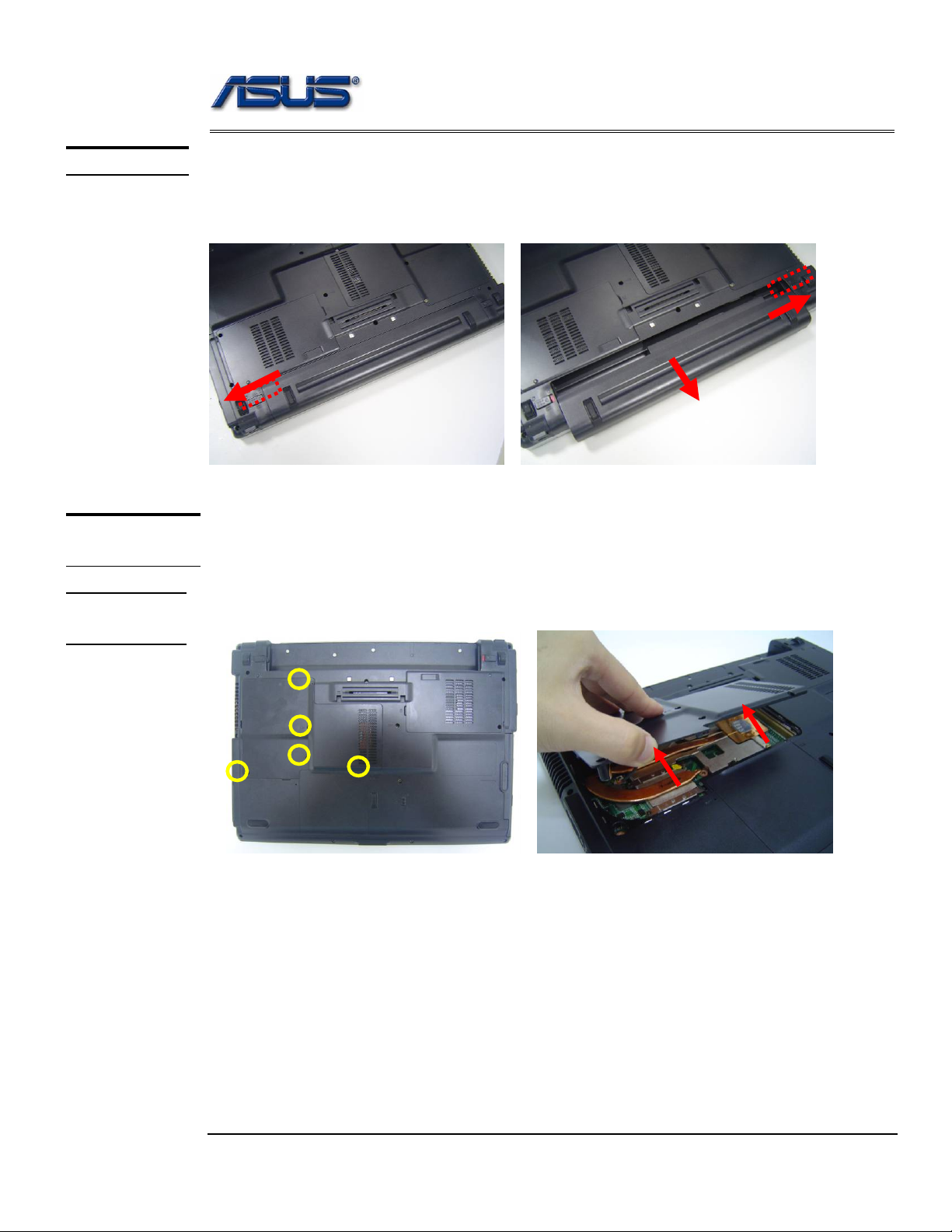
Battery Module
The illustration below shows how to remove the battery module.
Remove battery module
1. Turn the notebook over. Unlock and hold the latch, and remove the battery.
2
3
1
CPU Module
The illustrations below show ho w to remove the CPU module from the notebook.
Removing CPU
1. Remove 5 screws (M2*5) and take the CPU door away.
M2*5
2 - 2
Page 3
Disassembly procedure
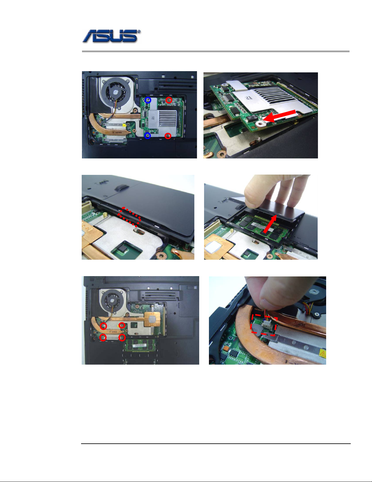
Remove VGA board module
2. Remove 4 screws(M2*5)(M2*3),then remove the VGA board module
M2*5
M2*3
3. Remove the DIMM cover from the bottom case.
4. Remove 4 screws (M2*5) aside the CPU. And disconnect the CPU fan cable..
M2*5
2 - 3
Page 4
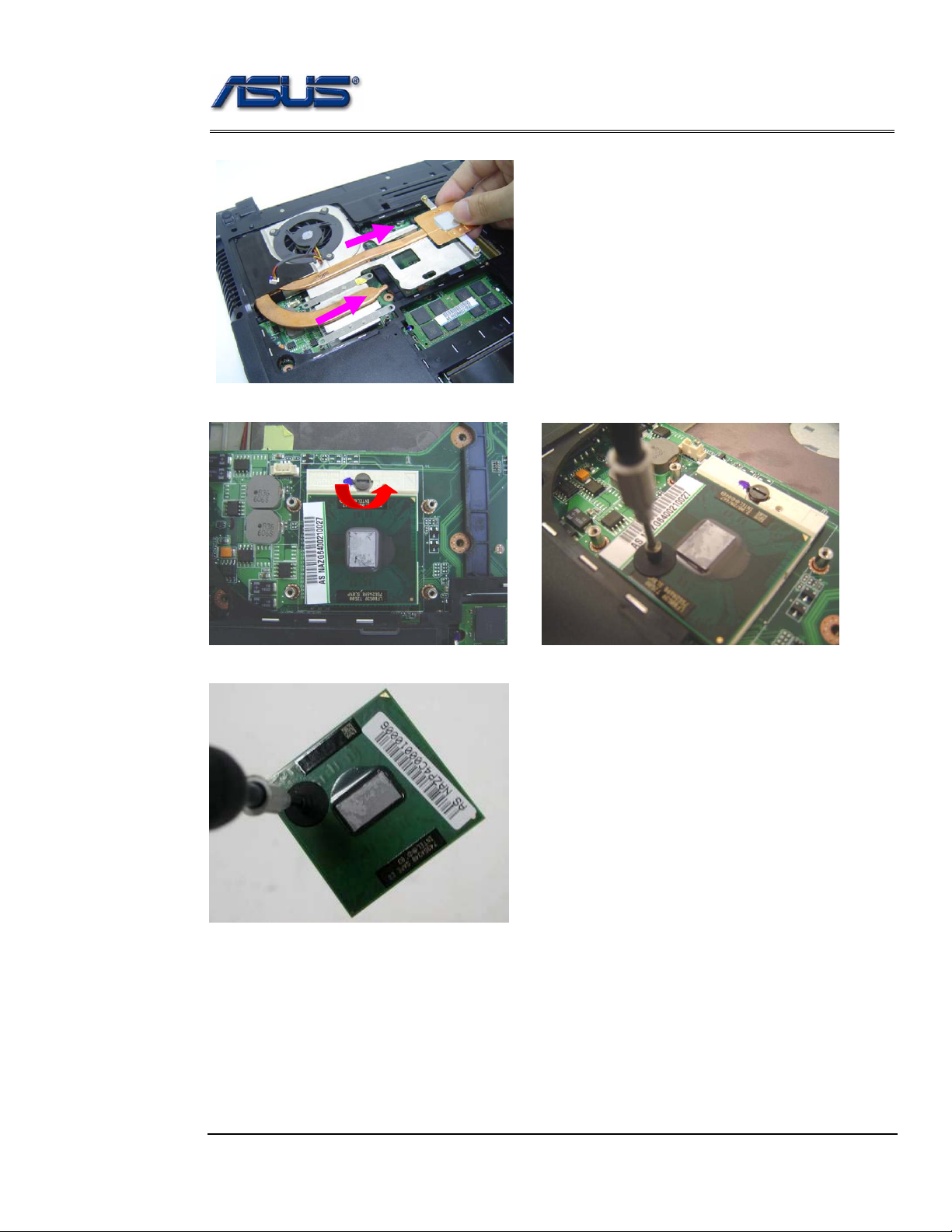
Disassembly procedure
5. Remove the CPU thermal module from the bottom case.
6. Turn the non-removable screw here 180 degrees counter-clockwise to loosen the CPU.
7. Squeeze the vacuum handling pump and use it to lift the CPU away.
2 - 4
Page 5
Disassembly procedure
MEMORY
MODULE
MEMORY
REMOVAL
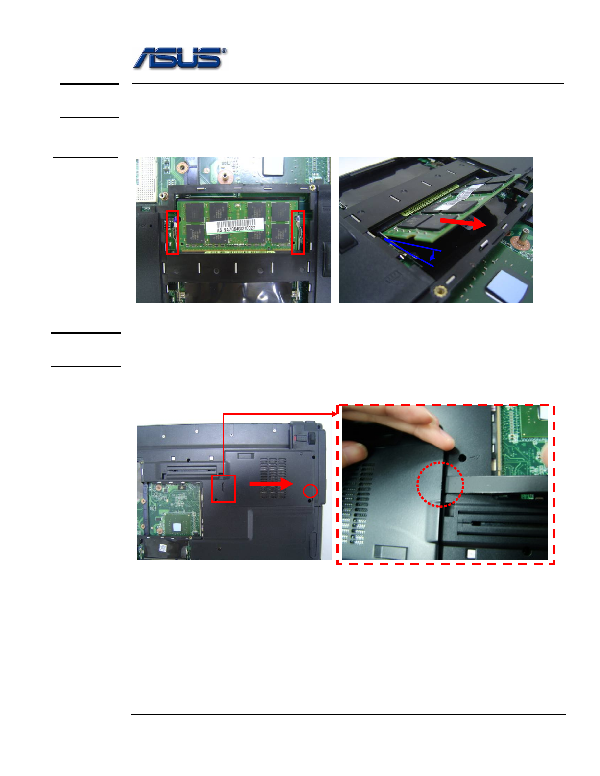
Memory Module
The illustration shows how to remove the memory module form the notebook.
Removing Memory module
1. Pull two latches and pop the module up to a 45° angles, and then pulling out the module in that
angle.
45o
HDD
MODULE
HDD
MODULE
REMOVAL
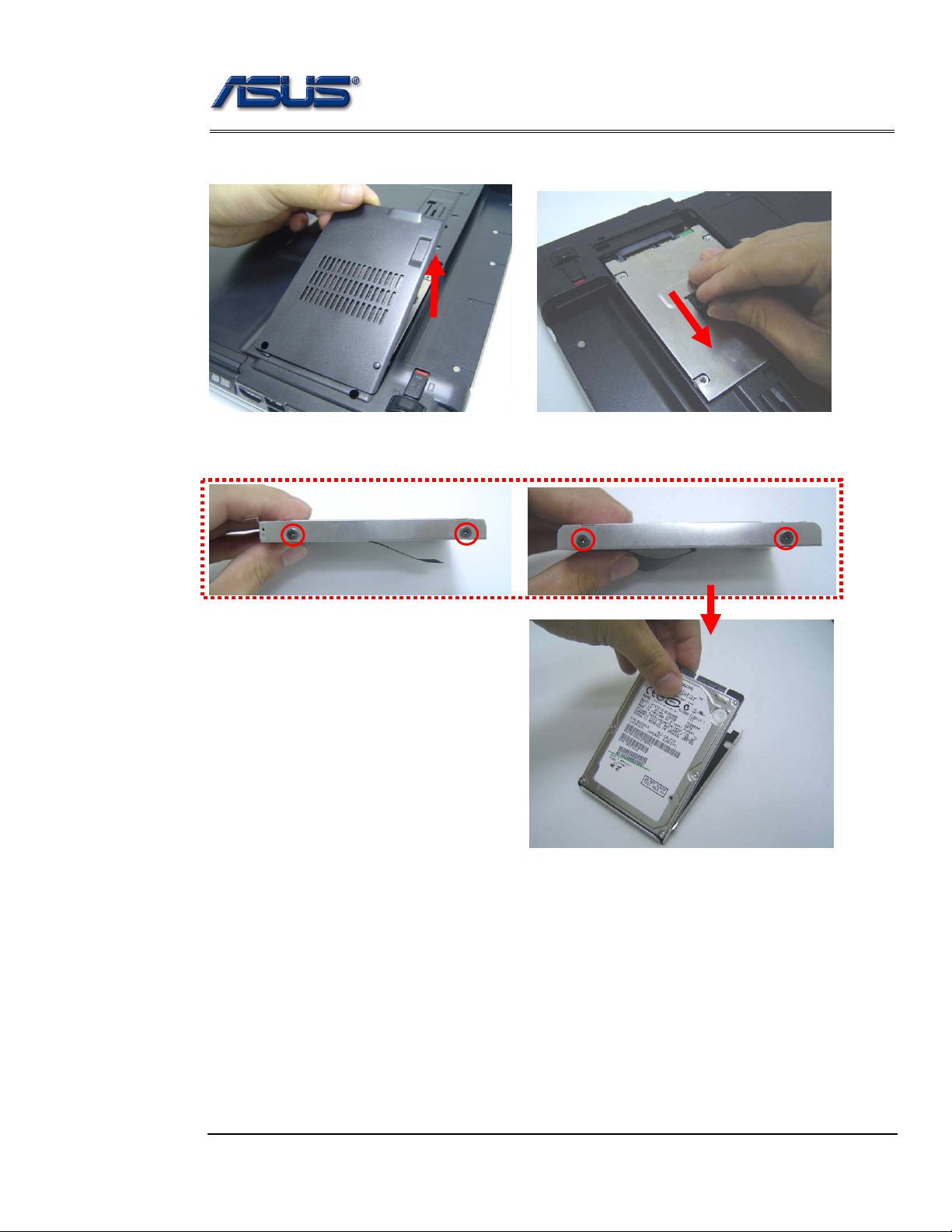
HDD Module
The illustrations below show ho w to remove the HDD m odule from the notebo ok.
Removing HDD Module
1. Remove 1 screw (M2*5) here, open HDD door by the tweezers and then take away the HDD
door.
2 - 5
Page 6
Disassembly procedure
2. Remove the HDD door from the bottom case and then put the HDD module.
3. Remove 4 screws (M3*3) to separate HDD from HDD housing
2 - 6
Page 7
Disassembly procedure
OPTICAL
DRIVE
REMOVAL
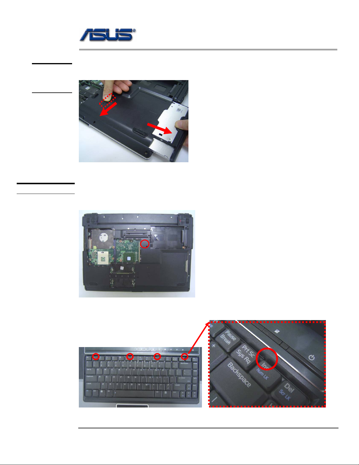
Optical Drive Module
1. Unlock and hold the latch, and remove the ODD module.
Keyboard Module
KEYBOARD
The illustration of below shows how to remove th e keyboard
Removing Keyboard
1. Remove 1 screw (M2*5) here, and then turn over the notebook.
2. Push the 4 latches in (F1, F6, F10, Ins) with a pair of tweezers or a single-slotted
screwdriver and lift the keyboard plate up.
2 - 7
Page 8

Disassembly procedure
3. Lay the keyboard down over the Top case. *Do not remove the keyboard yet.
The keyboard cable is still attached.
4. Disconnect the FPC connector by a pair of tweezers.
Removing Keyboard Cable
1. Use a flexible connector tool to unlock the cable connector on both ends (no. 1).
2. Carefully pull out the keyboard cable (no. 2) with a pair of tweezers.
3. Lock the connector (no. 3) again to avoid possible breakage.
2. Cable out
1. Unlock
3.
1. Unlock
3.
4. Remove keyboard from the top case.
2 - 8
Page 9

Disassembly procedure
TOP CASE
MODULE
T op Case Module
The illustrations below show how to disassemble and remove the top case module of the notebook.
The module contains the top case itself.
TOP CASE
REMOVAL
Removing Top Case Module
1. Use a pair of tweezers to remove both hinge Cover.
2. Use a pair of tweezers to disconnect both speaker cables.
2 - 9
Page 10

Disassembly procedure
3. Disconnect the touchpad FPC and antenna.
Antenna
Touchpad FPC
4. Disconnect the LCD cable and inverter cable and switch board FFC.
inverter cable
LCD cable
Switch board cable
Open the latch
2 - 10
Page 11

Disassembly procedure
5. Remove 2 screws (M2*5) here.
6. Turn over the notebook and then remove 17 screws here.
M2.5*2
M2*5
Separate the Top case from the bottom case.
7.
M2*4
2 - 11
Page 12

Disassembly procedure
8. Separate the antenna from the top case.
9. Remove 8 screws (M2.5*6) here.
10. Separate the top case from the LCD module.
2 - 12
Page 13

Disassembly procedure
11. Remove 4 screws (M2*3) here and then take away the speaker.
12. Remove 4 screws (M2*2.5) here then take away the switch board.
13. Disconnect the Bluetooth cable and remove Bluetooth Mylar.
Then remove Bluetooth module from the top case.
2 - 13
Page 14

Disassembly procedure
14. Remove 3 screws (M2*3) here then take away the touchpad bracket.
15. Remove 6 screws (M2*3) here and then take away the touchpad board.
16. Use a pair of tweezers to disconnect touchpad cable and FFC cable..
2 - 14
Page 15

Disassembly procedure
17. Remove 2 screws (M2*3) here and then take away the touchpad module from the top case.
WLAN
MODULE
WLAN
MODULE
REMOVAL
WLAN Module
The illustrations below show ho w to remove the WLAN modul e from the notebo ok.
Remove WLAN module
1. Remove 2 Antenna cables from Wireless LAN Module
2. Pull two latches and pop the module up to a 45° angles, and then pulling out the module in that
angle.
45o
2 - 15
Page 16

Disassembly procedure
3 G CARD
&
ROBSON
CARD
MOTHERBOARD
MOTHERBOARD
REMOVAL
3 G Card and Robson Card
The disassembly method of 3 G ca rd and Robso n card goes t he same wit h that of the WLAN m odule.
Robson card3 G card
Motherboard
The illustrations below show how to disassemble and remove the Motherboard.
Removing Motherboard
1. Disconnect the modem cable to motherboard.
2. Remove 2 screws here and then take away the modem module.
2 - 16
Page 17

Disassembly procedure
3. Remove 6 screws here.
M2*5
M2*8
4. Separate the Motherboard from the bottom case.
5. Disconnect the DC IN board cable from the motherboard and then take away the board.
2 - 17
Page 18

Disassembly procedure
6. Remove the 1 screw here the take away the TPM Board.
7. Disconnect the ODD FPC from the mother board.
2 - 18
Page 19

Disassembly procedure
LCD MODULE
LCD MODULE
DISASSEMBLY
LCD Module
The illustrations below show how to remove and disassemble the LCD module. The
module contains LCD panel, Inverter board, LCD bezel, LCD back cover.
Disassembling LCD Module
1. Remove 6 rubber pads and 6 screws (M2*5)from LCD module.
2. Prying the inside edges of the LCD bezel, and then separates it from LCD back cover.
3. Remove 1 screw (M2*3) here.
2 - 19
Page 20

Disassembly procedure
4. Disconnect the LCD cable. and inverter cable and then remove inverter board.
5. Remove 4screws (M2*5) and take away the LCD panel.
2 - 20
Page 21

Disassembly procedure
6. Remove the LCD plane from the LCD back cover.
7. Remove 4 screws (M2*3) on the right LCD bracket to disassemble the LCD bracket.
8. Remove 4 screws (M2*3) on the left LCD bracket to disassemble the other LCD bracket.
2 - 21
Page 22

Disassembly procedure
9. Disconnect the coaxial cable from LCD plane then take it away.
10. Remove 4 screws (M2*3) here then take away the LCD bracket.
11 Remove 2 screws (M2*5) here and take them away.
2 - 22
Page 23

Disassembly procedure
12. Remove 6 pieces of tapes then take away the camera module.
13. Remove 1 screw and 4 pieces of tapes then take away the wireless black wire.
14. Remove 1 screw and 3 pieces of tapes then take away the white wire.
2 - 23
 Loading...