

Page 1

ROG
STRIX Z490-F
BIOS Manual
Motherboard
Page 2

E16886
First Edition
August 2020
Copyright© 2020 ASUSTeK COMPUTER INC. All Rights Reserved.
No part of this manual, including the products and software described in it, may be reproduced,
transmitted, transcribed, stored in a retrieval system, or translated into any language in any form or by
any means, except documentation kept by the purchaser for backup purposes, without the express
written permission of ASUSTeK COMPUTER INC. (“ASUS”).
Product warranty or service will not be extended if: (1) the product is repaired, modified or altered, unless
such repair, modification of alteration is authorized in writing by ASUS; or (2) the serial number of the
product is defaced or missing.
ASUS PROVIDES THIS MANUAL “AS IS” WITHOUT WARRANTY OF ANY KIND, EITHER EXPRESS
OR IMPLIED, INCLUDING BUT NOT LIMITED TO THE IMPLIED WARRANTIES OR CONDITIONS OF
MERCHANTABILITY OR FITNESS FOR A PARTICULAR PURPOSE. IN NO EVENT SHALL ASUS, ITS
DIRECTORS, OFFICERS, EMPLOYEES OR AGENTS BE LIABLE FOR ANY INDIRECT, SPECIAL,
INCIDENTAL, OR CONSEQUENTIAL DAMAGES (INCLUDING DAMAGES FOR LOSS OF PROFITS,
LOSS OF BUSINESS, LOSS OF USE OR DATA, INTERRUPTION OF BUSINESS AND THE LIKE),
EVEN IF ASUS HAS BEEN ADVISED OF THE POSSIBILITY OF SUCH DAMAGES ARISING FROM
ANY DEFECT OR ERROR IN THIS MANUAL OR PRODUCT.
SPECIFICATIONS AND INFORMATION CONTAINED IN THIS MANUAL ARE FURNISHED FOR
INFORMATIONAL USE ONLY, AND ARE SUBJECT TO CHANGE AT ANY TIME WITHOUT NOTICE,
AND SHOULD NOT BE CONSTRUED AS A COMMITMENT BY ASUS. ASUS ASSUMES NO
RESPONSIBILITY OR LIABILITY FOR ANY ERRORS OR INACCURACIES THAT MAY APPEAR IN
THIS MANUAL, INCLUDING THE PRODUCTS AND SOFTWARE DESCRIBED IN IT.
Products and corporate names appearing in this manual may or may not be registered trademarks or
copyrights of their respective companies, and are used only for identification or explanation and to the
owners’ benefit, without intent to infringe.
2
ROG STRIX Z490-F BIOS Manual
Page 3

Contents
1. Knowing BIOS ............................................................................................... 4
2. BIOS setup program ..................................................................................... 5
2.1 Advanced Mode ............................................................................. 6
2.2 EZ Mode......................................................................................... 9
2.3 QFan Control................................................................................ 10
2.4 AI OC Guide ................................................................................. 12
3. My Favorites ................................................................................................ 13
4. Main menu ................................................................................................... 15
5. Ai Tweaker menu ......................................................................................... 17
6. Advanced menu .......................................................................................... 39
6.1 Platform Misc Configuration ......................................................... 40
6.2 CPU Configuration ....................................................................... 41
6.3 System Agent (SA) Configuration ................................................ 44
6.4 PCH Configuration ....................................................................... 46
6.5 PCH Storage Configuration.......................................................... 46
6.6 PCH-FW Configuration ................................................................ 47
6.7 Thunderbolt(TM) Configuration .................................................... 48
6.8 PCI Subsystem Settings .............................................................. 50
6.9 USB Configuration ....................................................................... 51
6.10 Network Stack Configuration........................................................ 52
6.11 NVMe Configuration ..................................................................... 52
6.12 Onboard Devices Configuration ................................................... 53
6.13 APM Configuration ....................................................................... 55
6.14 HDD/SSD SMART Information .................................................... 56
7. Monitor menu .............................................................................................. 57
8. Boot menu ................................................................................................... 64
9. Tool menu .................................................................................................... 69
9.1 ASUS EZ Flash 3 Utility ............................................................... 70
9.2 ASUS Secure Erase..................................................................... 70
9.3 ASUS User Profile........................................................................ 71
9.4 ASUS SPD Information ................................................................ 72
9.5 ASUS Armoury Crate ................................................................... 72
10. Exit menu ..................................................................................................... 73
11. Updating BIOS ............................................................................................. 74
11.1 EZ Update .................................................................................... 74
11.2 ASUS EZ Flash 3 ......................................................................... 75
11.3 ASUS CrashFree BIOS 3 ............................................................. 76
ROG STRIX Z490-F BIOS Manual
3
Page 4

BIOS Setup
1. Knowing BIOS
The new ASUS UEFI BIOS is a Unified Extensible Interface that complies with UEFI
architecture, offering a user-friendly interface that goes beyond the traditional keyboardonly BIOS controls to enable a more flexible and convenient mouse input. You can easily
navigate the new UEFI BIOS with the same smoothness as your operating system. The
term “BIOS” in this user manual refers to “UEFI BIOS” unless otherwise specified.
BIOS (Basic Input and Output System) stores system hardware settings such as storage
device configuration, overclocking settings, advanced power management, and boot
device configuration that are needed for system startup in the motherboard CMOS. In
normal circumstances, the default BIOS settings apply to most conditions to ensure
optimal performance. DO NOT change the default BIOS settings except in the following
circumstances:
• An error message appears on the screen during the system bootup and requests you
to run the BIOS Setup.
• You have installed a new system component that requires further BIOS settings or
update.
Inappropriate BIOS settings may result to instability or boot failure. We strongly
recommend that you change the BIOS settings only with the help of a trained
service personnel.
• When downloading or updating the BIOS file for your motherboard, rename it as
XXXXX.CAP. The name of the CAP file varies depending on models. Refer to the
user manual that came with your motherboard for the name.
• The screenshots in this manual are for reference only, please refer to the latest BIOS
version for settings and options.
• BIOS settings and options may vary due to different BIOS release versions or CPU
installed. Please refer to the latest BIOS version for settings and options.
4
ROG STRIX Z490-F BIOS Manual
Page 5

2. BIOS setup program
Use the BIOS Setup to update the BIOS or configure its parameters. The BIOS screen
include navigation keys and brief onscreen help to guide you in using the BIOS Setup
program.
Entering BIOS at startup
To enter BIOS Setup at startup, press <Delete> or <F2> during the Power-On Self Test
(POST). If you do not press <Delete> or <F2>, POST continues with its routines.
Entering BIOS Setup after POST
To enter BIOS Setup after POST:
• Press <Ctrl>+<Alt>+<Delete> simultaneously.
• Press the reset button on the system chassis.
• Press the power button to turn the system off then back on. Do this option only if you
failed to enter BIOS Setup using the first two options.
After doing either of the three options, press <Delete> key to enter BIOS.
• The BIOS setup screens shown in this section are for reference purposes only, and
may not exactly match what you see on your screen.
• Ensure that a USB mouse is connected to your motherboard if you want to use the
mouse to control the BIOS setup program.
• If the system becomes unstable after changing any BIOS setting, load the default
settings to ensure system compatibility and stability. Select the Load Optimized
Defaults item under the Exit menu or press hotkey <F5>. See section Exit menu for
details.
• If the system fails to boot after changing any BIOS setting, try to clear the CMOS
and reset the motherboard to the default value. See your motherboard manual for
information on how to erase the RTC RAM.
• The BIOS setup program does not support Bluetooth devices.
BIOS menu screen
The BIOS Setup program can be used under two modes: EZ Mode and Advanced Mode.
You can change modes from Setup Mode in Boot menu or by pressing the <F7> hotkey.
The BIOS settings and options for each motherboard may differ slightly with the options in
this manual. Please refer to the BIOS of your motherboard for the settings and options.
ROG STRIX Z490-F BIOS Manual
5
Page 6

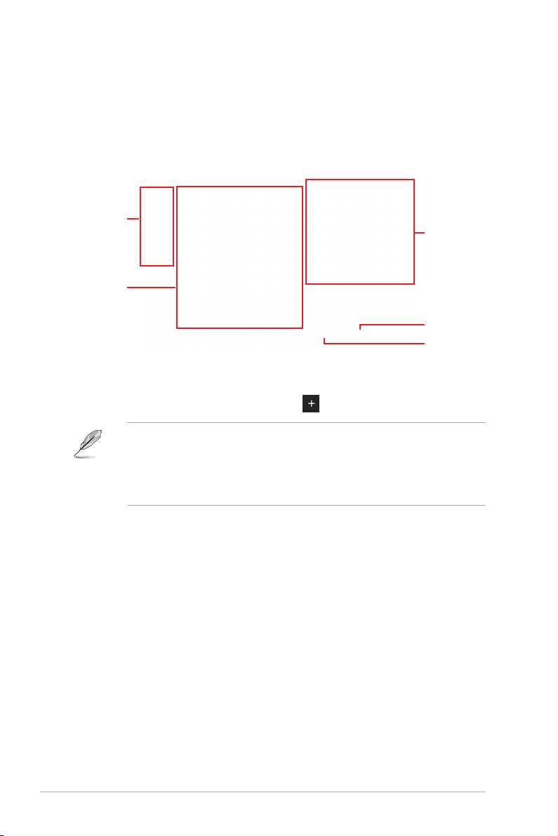
2.1 Advanced Mode
The Advanced Mode provides advanced options for experienced end-users to configure
the BIOS settings. The figure below shows an example of the Advanced Mode. Refer to the
following sections for the detailed configurations.
The default screen for entering the BIOS setup program can be changed. Refer to the
Setup Mode item in section Boot menu for details.
Configuration fields
Pop-up Menu
Menu bar
Language Qfan Control(F6)
Menu items
MyFavorite(F3)
General help
Search(F9)
AI OC Guide(F11)
Last modified settings Go back to EZ Mode
Scroll bar
AURA ON/OFF(F4)
Hot keys
Displays a quick overview of the
system status and prediction
6
ROG STRIX Z490-F BIOS Manual
Page 7

Menu bar
The menu bar on top of the screen has the following main items:
My Favorites
Main
Ai Tweaker
Advanced
Monitor
Boot
Tool
Exit
For saving the frequently-used system settings and configuration.
For changing the basic system configuration
For changing the overclocking settings
For changing the advanced system settings
For displaying the system temperature, power status, and changing
the fan settings.
For changing the system boot configuration
For configuring options for special functions
For selecting the exit options and loading default settings
Menu items
The highlighted item on the menu bar displays the specific items for that menu. For example,
selecting Main shows the Main menu items.
The other items (My Favorites, Ai Tweaker, Advanced, Monitor, Boot, Tool, and Exit) on the
menu bar have their respective menu items.
Submenu items
An arrow sign (>) before each item on any menu screen means that the item has a
submenu. To display the submenu, select the item and press <Enter>.
Language
This button above the menu bar contains the languages that you can select for your BIOS.
Click this button to select the language that you want to display in your BIOS screen.
My Favorite (F3)
This button above the menu bar shows all BIOS items in a Tree Map setup. Select
frequently-used BIOS settings and save it to My Favorites menu.
Refer to section My Favorites for more information.
QFan Control (F6)
This button above the menu bar displays the current settings of your fans. Use this button to
manually tweak the fans to your desired settings.
Refer to section QFan Control for more information.
AI OC Guide(F11)
This button above the menu bar allows you to view the descriptions of AI overclocking and
enable it.
• Refer to section AI OC Guide for more information.
• This function is only enabled when using an unlocked CPU.
ROG STRIX Z490-F BIOS Manual
7
Page 8

Search (F9)
This button allows you to search for BIOS items by entering its name, enter the item name to
find the related item listing.
AURA ON/OFF(F4)
This button allows you to turn the RGB LED lighting or functional LED on or off.
[All On]: All LEDs (Aura or Functional) will be enabled.
[Aura Only]: Aura LEDs will be enabled and functional LEDs will be disabled.
[Aura Off]: Aura LEDs will be disabled, however functional LEDs will still be enabled.
[Stealth Mode]: All LEDs (Aura and Functional) will be disabled.
Hot keys
This button above the menu bar contains the navigation keys for the BIOS setup program.
Use the navigation keys to select items in the menu and change the settings.
Scroll bar
A scroll bar appears on the right side of a menu screen when there are items that do not fit
on the screen. Press the Up/Down arrow keys or <Page Up> / <Page Down> keys to display
the other items on the screen.
General help
At the bottom of the menu screen is a brief description of the selected item. Use <F12> key
to capture the BIOS screen and save it to the removable storage device.
Configuration fields
These fields show the values for the menu items. If an item is user-configurable, you can
change the value of the field opposite the item. You cannot select an item that is not userconfigurable.
A configurable field is highlighted when selected. To change the value of a field, select it and
press <Enter> to display a list of options.
Last Modified button
This button shows the items that you last modified and saved in BIOS Setup.
8
ROG STRIX Z490-F BIOS Manual
Page 9

2.2 EZ Mode
The EZ Mode provides you an overview of the basic system information, and allows you to
select the display language, system performance, mode and boot device priority. To access
the Advanced Mode, select Advanced Mode or press the <F7> hotkey for the advanced
BIOS settings.
To switch from Advanced Mode to EZ Mode, click EZ Mode(F7) or press the <F7> hotkey.
Displays a quick overview of the
system status
Enables or disables the SATA RAID mode
for Intel Rapid Storage Technology
Selects the display language
of the BIOS setup program
Displays the CPU Fan’s speed. Click
the button to manually tune the fans
Displays the system properties of the selected mode.
Search(F9)AI OC Guide(F11) AURA ON/OFF(F4)
Loads optimized
default settings
Click < or > to switch modes
Saves the changes
and resets the system
Click to go to Advanced mode
Click to display boot devices
Selects the boot device priority
The boot device options vary depending on the devices you installed to the system.
ROG STRIX Z490-F BIOS Manual
9
Page 10

2.3 QFan Control
The QFan Control allows you to set a fan profile or manually configure the operating speed
of your CPU and chassis fans.
Click to select a fan to be
configured
Click to activate
PWM Mode
Click to activate DC Mode
Select a profile to
apply to your fans
10
Click to apply the fan setting
Click to undo the
changes
Click to go back to main menu
Select to manually configure
your fans
ROG STRIX Z490-F BIOS Manual
Page 11

Configuring fans manually
Select Manual from the list of profiles to manually configure your fans’ operating speed.
Speed points
Select to manually
configure your fans
To configure your fans:
1. Select the fan that you want to configure and to view its current status.
2. Click and drag the speed points to adjust the fans’ operating speed.
3. Click Apply to save the changes then click Exit (ESC).
ROG STRIX Z490-F BIOS Manual
11
Page 12

2.4 AI OC Guide
• The screenshot shown in this section is for reference purposes only, and may not
exactly match what you see on your screen.
• This function is only enabled when using an unlocked CPU.
The AI OC Guide allows you to enable the Ai Overclocking feature, or view a quick guide
of the Ai Overclocking feature which highlights the recommended setup procedure and
descriptions of the AI Overclocking.
Clicking on Enable AI will enable AI Overclocking.
Quick guide topics Click to go back
Click to view the
previous topic in the
quick guide
12
Click to view
the next topic in
the quick guide
ROG STRIX Z490-F BIOS Manual
Click to enable AI
Overclocking
to main menu
Page 13

3. My Favorites
My Favorites is your personal space where you can easily save and access your favorite
BIOS items. You can personalize this screen by adding or removing items.
ROG STRIX Z490-F BIOS Manual
13
Page 14
Adding items to My Favorites
To add BIOS items:
1. Press <F3> on your keyboard or click MyFavorite(F3) from the BIOS screen to open
Setup Tree Map screen.
2. On the Setup Tree Map screen, select the BIOS items that you want to save in My
Favorites screen.
Main menu panel
Selected shortcut
items
Submenu panel
Delete all favorite
items
Recover to default
favorite items
3. Select an item from main menu panel, then click the submenu that you want to save
as favorite from the submenu panel and click
You cannot add the following items to My Favorite items:
• Items with submenu options.
• User-managed items such as language and boot order.
• Configuration items such as Memory SPD Information, system time and date.
or press <Enter> on your keyboard.
4. Click Exit (ESC) or press <Esc> key to close Setup Tree Map screen.
5. Go to My Favorites menu to view the saved BIOS items.
14
ROG STRIX Z490-F BIOS Manual
Page 15

4. Main menu
The Main menu screen appears when you enter the Advanced Mode of the BIOS Setup
program. The Main menu provides you an overview of the basic system information, and
allows you to set the system date, time, language, and security settings.
Security
The Security menu items allow you to change the system security settings.
ROG STRIX Z490-F BIOS Manual
15
Page 16

• If you have forgotten your BIOS password, erase the CMOS Real Time Clock (RTC)
RAM to clear the BIOS password. See the motherboard for information on how to
erase the RTC RAM via the Clear CMOS header.
• The Administrator or User Password items on top of the screen show the default [Not
Installed]. After you set a password, these items show [Installed].
Administrator Password
If you have set an administrator password, we recommend that you enter the administrator
password for accessing the system. Otherwise, you might be able to see or change only
selected fields in the BIOS setup program.
To set an administrator password:
1. Select the Administrator Password item and press <Enter>.
2. From the Create New Password box, key in a password, then press <Enter>.
3. Re-type to confirm the password then select OK.
To change an administrator password:
1. Select the Administrator Password item and press <Enter>.
2. From the Enter Current Password box, key in the current password, then press
<Enter>.
3. From the Create New Password box, key in a new password, then press <Enter>.
4. Re-type to confirm the password then select OK.
To clear the administrator password, follow the same steps as in changing an administrator
password, but leave other fields blank then select OK to continue. After you clear the
password, the Administrator Password item on top of the screen shows [Not Installed].
User Password
If you have set a user password, you must enter the user password for accessing the
system. The User Password item on top of the screen shows the default [Not Installed].
After you set a password, this item shows [Installed].
To set a user password:
1. Select the User Password item and press <Enter>.
2. From the Create New Password box, key in a password, then press <Enter>.
3. Re-type to confirm the password then select OK.
To change a user password:
1. Select the User Password item and press <Enter>.
2. From the Enter Current Password box, key in the current password, then press
<Enter>.
3. From the Create New Password box, key in a new password, then press <Enter>.
4. Re-type to confirm the password then select OK.
To clear the user password, follow the same steps as in changing a user password, but
leave other fields blank then select OK to continue. After you clear the password, the User
Password item on top of the screen shows [Not Installed].
16
ROG STRIX Z490-F BIOS Manual
Page 17

5. Ai Tweaker menu
The Ai Tweaker menu items allow you to configure overclocking-related items.
Be cautious when changing the settings of the Ai Tweaker menu items. Incorrect field
values can cause the system to malfunction.
The configuration options for this section vary depending on the CPU and DIMM model
you installed on the motherboard.
Scroll down to display other BIOS items.
ROG STRIX Z490-F BIOS Manual
17
Page 18

Ai Overclock Tuner
This item allows you to select the CPU overclocking options to achieve the desired CPU
internal frequency. Select any of these preset overclocking configuration options:
[Auto] Loads the optimal settings for the system.
[Manual] When the manual mode is selected, the BCLK (base clock) frequency can
[XMP I] If you install memory modules supporting the eXtreme Memory Profile
[XMP II] If you install memory modules supporting the eXtreme Memory Profile
XMP
This item allows you to select your eXtreme Memory Profile (XMP). Each profile has
its own DRAM frequency, timing and voltage.
BCLK Frequency
This item allows you to set the BCLK (base clock) frequency to enhance the system
performance. Use the <+> or <-> to adjust the value.
be assigned manually.
(XMP) Technology, choose this item to load the DIMM’s default XMP
memory timings (CL, TRCD, TRP, TRAS) with BCLK frequency and other
memory parameters optimized by ASUS.
(XMP) Technology, choose this item to load the DIMM’s default XMP
profile.
The [X.M.P.] configuration option appears only when you install memory modules
supporting the eXtreme Memory Profile(X.M.P.) Technology.
The following item appears only when Ai Overclock Tuner is set to [XMP I] or [XMP II].
The following items appear only when Ai Overclock Tuner is set to [XMP I], [XMP II], or
[Manual].
We recommend you to set the value based on the CPU specification, as high BCLK
frequencies may damage the CPU permanently.
BCLK Spread Spectrum
This item allows you to enable or disable the BCLK Spread Spectrum. When set to
[Enabled] the peak value of EMI emissions is reduced. Set to [Disabled] for a more
accurate Base Clock.
Configuration options: [Auto] [Disabled] [Enabled]
ASUS MultiCore Enhancement
[Auto - Lets BIOS Optimize] This item allows you to use ASUS optimized core ratio
[Disabled - Enforce All limits] This item allows you to use Intel default Turbo core ratio
[Enabled - Remove All limits] This item allows you to use optimized power and current
18
Turbo settings at default processor speeds.
settings.
thresholds for maintaining maximum performance.
ROG STRIX Z490-F BIOS Manual
Page 19

SVID Behavior
This item allows you to program the CPU’s SVID behavior based on the CPU’s quality. The
default option is based on [Typical Scenario], but the more optimistic the mode selected,
the lower the temperature of the CPU. [Intel’s Fail Safe] is the default behavior of the
processor oblivious to the actual Motherboard design. [Trained] optimizes SVID behavior to
match input parameters such as VRM Loadline and Target Frequencies.
Configuration options: [Auto] [Best-Case Scenario] [Typical Scenario] [Worst-Case Scenario]
[Intel’s Fail Safe] [Trained]
AVX Instruction Core Ratio Negative Offset
This item allows you to subtract a value from your core ratio at which AVX applications run.
Configuration options: [Auto] [0] - [31]
CPU Core Ratio
This item allows you to set the CPU core ratios.
Configuration options: [Auto] [Sync All Cores] [By Core Usage] [AI Optimized]
The [AI Optimized] item appears only when you use an unlocked CPU.
The following item appears only when CPU Core Ratio is set to [Sync All Cores].
ALL-Core Ratio Limit
Enter [Auto] to apply the CPU default Turbo Ratio setting or manually
assign a Core ratio limit to synchronize all cores.
The following items appear only when CPU Core Ratio is set to [By Core Usage].
1-Core Ratio Limit
Enter [Auto] to apply the CPU default Turbo Ratio setting or manually
assign a 1-Core Limit value that must be lower than or equal to the second
biggest core’s Ratio Limit.
2-Core Ratio Limit
Enter [Auto] to apply the CPU default Turbo Ratio setting or manually
assign a 2-core ratio limit that must be lower than or equal to the second
biggest core’s Ratio Limit.
If you assign a value for 2-Core Ratio Limit, do not set the 1-Core Ratio Limit to [Auto].
3-Core Ratio Limit
Enter [Auto] to apply the CPU default Turbo Ratio setting or manually
assign a 3-core ratio limit that must be lower than or equal to the second
biggest core’s Ratio Limit.
If you assign a value for 3-Core Ratio Limit, do not set the 1-Core Ratio Limit and 2-Core
Ratio Limit to [Auto].
ROG STRIX Z490-F BIOS Manual
19
Page 20

4-Core Ratio Limit
Enter [Auto] to apply the CPU default Turbo Ratio setting or manually
assign a 4-core ratio limit that must be lower than or equal to the second
biggest core’s Ratio Limit.
If you assign a value for 4-Core Ratio Limit, do not set the 1-Core Ratio Limit, 2-Core
Ratio Limit, and 3-Core Ratio Limit to [Auto].
5-Core Ratio Limit
Enter [Auto] to apply the CPU default Turbo Ratio setting or manually
assign a 5-core ratio limit that must be lower than or equal to the second
biggest core’s Ratio Limit.
If you assign a value for 4-Core Ratio Limit, do not set the 1-Core Ratio Limit, 2-Core
Ratio Limit, 3-Core Ratio Limit, and 4-Core Ratio Limit to [Auto].
6-Core Ratio Limit
Enter [Auto] to apply the CPU default Turbo Ratio setting or manually
assign a 6-core ratio limit that must be lower than or equal to the second
biggest core’s Ratio Limit.
If you assign a value for 4-Core Ratio Limit, do not set the 1-Core Ratio Limit, 2-Core Ratio
Limit, 3-Core Ratio Limit, 4-Core Ratio Limit, and 5-Core Ratio Limit to [Auto].
7-Core Ratio Limit
Enter [Auto] to apply the CPU default Turbo Ratio setting or manually
assign a 7-core ratio limit that must be lower than or equal to the second
biggest core’s Ratio Limit.
If you assign a value for 4-Core Ratio Limit, do not set the 1-Core Ratio Limit, 2-Core
Ratio Limit, 3-Core Ratio Limit, 4-Core Ratio Limit, 5-Core Ratio Limit, and 6-Core Ratio
Limit to [Auto].
8-Core Ratio Limit
Enter [Auto] to apply the CPU default Turbo Ratio setting or manually
assign a 8-core ratio limit that must be lower than or equal to the second
biggest core’s Ratio Limit.
If you assign a value for 4-Core Ratio Limit, do not set the 1-Core Ratio Limit, 2-Core
Ratio Limit, 3-Core Ratio Limit, 4-Core Ratio Limit, 5-Core Ratio Limit, 6-Core Ratio Limit,
and 7-Core Ratio Limit to [Auto].
The following items appear only when CPU Core Ratio is set to [AI Optimized].
Optimized AVX Frequency
Select Normal Use for typical use cases, select Heavy AVX for extreme
loads such as Prime 95 AVX.
Configuration options: [Normal use] [Heavy AVX]
20
ROG STRIX Z490-F BIOS Manual
Page 21

BCLK Frequency : DRAM Frequency Ratio
[Auto] The BCLK frequency to DRAM frequency ratio will be set to the optimized
[100:133] The BCLK frequency to DRAM frequency ratio will be set to 100:133.
[100:100] The BCLK frequency to DRAM frequency ratio will be set to 100:100.
setting.
DRAM Odd Ratio Mode
This item allows you to enable or disable availability of odd DRAM ratios for improved
granularity.
Configuration options: [Enabled] [Disabled]
DRAM Frequency
This item allows you to set the memory operating frequency. The configurable options vary
with the BCLK (base clock) frequency setting. Select the auto mode to apply the optimized
setting.
Configuration options: [Auto] [DDR4-800MHz] - [DDR4-8533MHz]
CPU SVID Support
Disable this item to stop the CPU from communicating with the external voltage regulator.
We recommend setting this item to [Disabled] for overclocking.
Configuration options: [Auto] [Disabled] [Enabled]
DRAM Timing Control
The sub-items in this menu allow you to set the DRAM timing control features. Use the
<+> and <-> keys to adjust the value. To restore the default setting, type [Auto] using the
keyboard and press the <Enter> key. You can also select various Memory Presets to load
settings suitably tuned for some memory modules.
Changing the values in this menu may cause the system to become unstable! If this
happens, revert to the default settings.
Primary Timings
DRAM CAS# Latency
Configuration options: [Auto] [1] - [31]
DRAM RAS# to CAS# Delay
Configuration options: [Auto] [1] - [63]
DRAM RAS# ACT Time
Configuration options: [Auto] [1] - [63]
DRAM Command Rate
Configuration options: [Auto] [1N] [2N] [3N] [N:1]
The following item appears only when DRAM Command Rate is set to [N:1].
N to 1 ratio
Number of bubbles between wach valid command cycle.
Configurations: [4] - [7]
ROG STRIX Z490-F BIOS Manual
21
Page 22

Secondary Timings
DRAM RAS# to RAS# Delay L
Configuration options: [Auto] [1] - [15]
DRAM RAS# to RAS# Delay S
Configuration options: [Auto] [1] - [15]
DRAM REF Cycle Time
Configuration options: [Auto] [1] - [1023]
DRAM REF Cycle Time 2
Configuration options: [Auto] [1] - [1023]
DRAM REF Cycle Time 4
Configuration options: [Auto] [1] - [1023]
DRAM Refresh Interval
Configuration options: [Auto] [1] - [65535]
DRAM WRITE Recovery Time
Configuration options: [Auto] [1] - [31]
DRAM READ to PRE Time
Configuration options: [Auto] [1] - [15]
DRAM FOUR ACT WIN Time
Configuration options: [Auto] [1] - [63]
DRAM WRITE to READ Delay
Configuration options: [Auto] [1] - [15]
DRAM WRITE to READ Delay L
Configuration options: [Auto] [1] - [15]
DRAM WRITE to READ Delay S
Configuration options: [Auto] [1] - [15]
DRAM CKE Minimum Pulse Width
Configuration options: [Auto] [0] - [15]
DRAM Write Latency
Configuration options: [Auto] [1] - [31]
Skew Control
ODT RTT WR (CHA)
Configuration options: [Auto] [0 DRAM CLOCK] [80 DRAM CLOCK] [120
DRAM CLOCK] [240 DRAM CLOCK] [255 DRAM CLOCK]
ODT RTT PARK (CHA)
Configuration options: [Auto] [0 DRAM CLOCK] [34 DRAM CLOCK]
[40 DRAM CLOCK] [48 DRAM CLOCK] [60 DRAM CLOCK] [80 DRAM
CLOCK] [120 DRAM CLOCK] [240 DRAM CLOCK]
ODT RTT NOM (CHA)
Configuration options: [Auto] [0 DRAM CLOCK] [34 DRAM CLOCK]
[40 DRAM CLOCK] [48 DRAM CLOCK] [60 DRAM CLOCK] [80 DRAM
CLOCK] [120 DRAM CLOCK] [240 DRAM CLOCK]
22
ROG STRIX Z490-F BIOS Manual
Page 23

ODT RTT WR (CHB)
Configuration options: [Auto] [0 DRAM CLOCK] [80 DRAM CLOCK] [120
DRAM CLOCK] [240 DRAM CLOCK] [255 DRAM CLOCK]
ODT RTT PARK (CHB)
Configuration options: [Auto] [0 DRAM CLOCK] [34 DRAM CLOCK]
[40 DRAM CLOCK] [48 DRAM CLOCK] [60 DRAM CLOCK] [80 DRAM
CLOCK] [120 DRAM CLOCK] [240 DRAM CLOCK]
ODT RTT NOM (CHB)
Configuration options: [Auto] [0 DRAM CLOCK] [34 DRAM CLOCK]
[40 DRAM CLOCK] [48 DRAM CLOCK] [60 DRAM CLOCK] [80 DRAM
CLOCK] [120 DRAM CLOCK] [240 DRAM CLOCK]
ODT_READ_DURATION
Configuration options: [Auto] [0] - [7]
ODT_READ_DELAY
Configuration options: [Auto] [0] - [7]
ODT_WRITE_DURATION
Configuration options: [Auto] [0] - [7]
ODT_WRITE_DELAY
Configuration options: [Auto] [0] - [7]
Data Rising Slope
Configuration options: [Auto] [0] - [15]
Data Rising Slope Offset
Configuration options: [Auto] [0] - [1]
Cmd Rising Slope
Configuration options: [Auto] [0] - [15]
Cmd Rising Slope Offset
Configuration options: [Auto] [0] - [1]
Ctl Rising Slope
Configuration options: [Auto] [0] - [15]
Ctl Rising Slope Offset
Configuration options: [Auto] [0] - [1]
Clk Rising Slope
Configuration options: [Auto] [0] - [15]
Clk Rising Slope Offset
Configuration options: [Auto] [0] - [1]
Data Falling Slope
Configuration options: [Auto] [0] - [15]
Data Falling Slope Offset
Configuration options: [Auto] [0] - [1]
Cmd Falling Slope
Configuration options: [Auto] [0] - [15]
ROG STRIX Z490-F BIOS Manual
23
Page 24

Cmd Falling Slope Offset
Configuration options: [Auto] [0] - [1]
Ctl Falling Slope
Configuration options: [Auto] [0] - [15]
Ctl Falling Slope Offset
Configuration options: [Auto] [0] - [1]
Clk Falling Slope
Configuration options: [Auto] [0] - [15]
Clk Falling Slope Offset
Configuration options: [Auto] [0] - [1]
RTL IOL Control
DRAM RTL INIT Value
Configuration options: [Auto] [0] - [127]
DRAM RTL (CHA DIMM0 Rank0)
Configuration options: [Auto] [0] - [127]
DRAM RTL (CHA DIMM0 Rank1)
Configuration options: [Auto] [0] - [127]
DRAM RTL (CHA DIMM1 Rank0)
Configuration options: [Auto] [0] - [127]
DRAM RTL (CHA DIMM1 Rank1)
Configuration options: [Auto] [0] - [127]
DRAM RTL (CHB DIMM0 Rank0)
Configuration options: [Auto] [0] - [127]
DRAM RTL (CHB DIMM0 Rank1)
Configuration options: [Auto] [0] - [127]
DRAM RTL (CHB DIMM1 Rank0)
Configuration options: [Auto] [0] - [127]
DRAM RTL (CHB DIMM1 Rank1)
Configuration options: [Auto] [0] - [127]
DRAM IOL (CHA DIMM0 Rank0)
Configuration options: [Auto] [0] - [15]
DRAM IOL (CHA DIMM0 Rank1)
Configuration options: [Auto] [0] - [15]
DRAM IOL (CHA DIMM1 Rank0)
Configuration options: [Auto] [0] - [15]
DRAM IOL (CHA DIMM1 Rank1)
Configuration options: [Auto] [0] - [15]
DRAM IOL (CHB DIMM0 Rank0)
Configuration options: [Auto] [0] - [15]
24
ROG STRIX Z490-F BIOS Manual
Page 25

DRAM IOL (CHB DIMM0 Rank1)
Configuration options: [Auto] [0] - [15]
DRAM IOL (CHB DIMM1 Rank0)
Configuration options: [Auto] [0] - [15]
DRAM IOL (CHB DIMM1 Rank1)
Configuration options: [Auto] [0] - [15]
IO Latency offset
CHA IO_Latency_offset
Configuration options: [Auto] [0] - [127]
CHB IO_Latency_offset
Configuration options: [Auto] [0] - [127]
IO Latency RFR delay
CHA RFR delay
Configuration options: [Auto] [0] - [127]
CHB RFR delay
Configuration options: [Auto] [0] - [127]
Memory Training Algorithms
The items in this menu allows you to enable or disable different Memory Training
Algorithms.
Early Command Training
Configuration options: [Auto] [Enabled] [Disabled]
SenseAmp Offset Training
Configuration options: [Enabled] [Disabled]
Early ReadMPR Timing Centering 2D
Configuration options: [Enabled] [Disabled]
Read MPR Training
Configuration options: [Enabled] [Disabled]
Receive Enable Training
Configuration options: [Enabled] [Disabled]
Jedec Write Leveling
Configuration options: [Enabled] [Disabled]
LPDDR4 Write DQ DQS Retraining
Configuration options: [Enabled] [Disabled]
Early Write Timing Centering 2D
Configuration options: [Auto] [Enabled] [Disabled]
Early Read Timing Centering 2D
Configuration options: [Auto] [Enabled] [Disabled]
Write Timing Centering 1D
Configuration options: [Enabled] [Disabled]
ROG STRIX Z490-F BIOS Manual
25
Page 26

Write Voltage Centering 1D
Configuration options: [Enabled] [Disabled]
Read Timing Centering 1D
Configuration options: [Enabled] [Disabled]
Dimm ODT Training*
Configuration options: [Auto] [Enabled] [Disabled]
DIMM RON Training*
Configuration options: [Auto] [Enabled] [Disabled]
Write Drive Strength/Equalization 2D*
Configuration options: [Auto] [Enabled] [Disabled]
Write Slew Rate Training*
Configuration options: [Enabled] [Disabled]
Read ODT Training*
Configuration options: [Enabled] [Disabled]
Read Equalization Training*
Configuration options: [Enabled] [Disabled]
Read Amplifier Training*
Configuration options: [Enabled] [Disabled]
Write Timing Centering 2D
Configuration options: [Enabled] [Disabled]
Read Timing Centering 2D
Configuration options: [Enabled] [Disabled]
Command Voltage Centering
Configuration options: [Enabled] [Disabled]
Write Voltage Centering 2D
Configuration options: [Enabled] [Disabled]
Read Voltage Centering 2D
Configuration options: [Auto] [Enabled] [Disabled]
Late Command Training
Configuration options: [Auto] [Enabled] [Disabled]
Round Trip Latency
Configuration options: [Auto] [Enabled] [Disabled]
Turn Around Timing Training
Configuration options: [Enabled] [Disabled]
Rank Margin Tool
Configuration options: [Auto] [Enabled] [Disabled] [Minimal]
Margin Check Limit
Checks Margin to Limit to see if next boot memory needs to be retrained.
Configuration options: [Disabled] [L1] [L2] [Both]
26
ROG STRIX Z490-F BIOS Manual
Page 27

The following item appears only when Margin Check Limit is set to [L2] or [Both].
Margin Limit Check L2
L2 check threshold is scale of L1 check.
Configuration options: [1] - [300]
Memory Test
Configuration options: [Enabled] [Disabled]
DIMM SPD Alias Test
Configuration options: [Auto] [Enabled] [Disabled]
Receive Enable Centering 1D
Configuration options: [Auto] [Enabled] [Disabled]
Retrain Margin Check
Configuration options: [Enabled] [Disabled]
CMD Drive Strength and Tx Equalization
Configuration options: [Auto] [Enabled] [Disabled]
CMD Slew Rate Training
Configuration options: [Auto] [Enabled] [Disabled]
Write Drive Strength Up/Dn independently
Configuration options: [Enabled] [Disabled]
Third Timings
tRDRD_sg_Training
Configuration options: [Auto] [0] - [63]
tRDRD_sg_Runtime
Configuration options: [Auto] [0] - [63]
tRDRD_dg
Configuration options: [Auto] [0] - [63]
tRDWR_sg
Configuration options: [Auto] [0] - [63]
tRDWR_dg
Configuration options: [Auto] [0] - [63]
tWRWR_sg
Configuration options: [Auto] [0] - [63]
tWRWR_dg
Configuration options: [Auto] [0] - [63]
tWRRD_sg
Configuration options: [Auto] [0] - [127]
tWRRD_dg
Configuration options: [Auto] [0] - [63]
ROG STRIX Z490-F BIOS Manual
27
Page 28

tRDRD_dr
Configuration options: [Auto] [0] - [63]
tRDRD_dd
Configuration options: [Auto] [0] - [63]
tRDWR_dr
Configuration options: [Auto] [0] - [63]
tRDWR_dd
Configuration options: [Auto] [0] - [63]
tWRWR_dr
Configuration options: [Auto] [0] - [63]
tWRWR_dd
Configuration options: [Auto] [0] - [63]
tWRRD_dr
Configuration options: [Auto] [0] - [63]
tWRRD_dd
Configuration options: [Auto] [0] - [63]
TWRPRE
Configuration options: [Auto] [0] - [127]
TRDPRE
Configuration options: [Auto] [0] - [15]
tREFIX9
Configuration options: [Auto] [0] - [127]
OREF_RI
Configuration options: [Auto] [0] - [255]
Misc.
MRC Fast Boot
Allows you to enable, disable or automatically set the MRC fast boot.
Configuration options: [Auto] [Enabled] [Disabled]
Delay after Train
This item allows you to enable 10 second delay after training for DRAM to reach a
certain temperature during extreme overclocking.
Configuration options: [Disabled] [Enabled]
DRAM CLK Period
This item allows you to set the DRAM clock period.
Configuration options: [Auto] [1] - [95]
Memory Scrambler
Set this item to enable or disable memory scrambler support.
Configuration options: [Enabled] [Disabled]
28
ROG STRIX Z490-F BIOS Manual
Page 29

Channel A DIMM Control
Allows you to enable or disable the Channel A DIMM slots.
Configuration options: [Enable Both DIMMs] [Disable DIMM0] [Disable DIMM1]
[Disable Both DIMMs]
Channel B DIMM Control
Allows you to enable or disable the Channel B DIMM slots.
Configuration options: [Enable Both DIMMs] [Disable DIMM0] [Disable DIMM1]
[Disable Both DIMMs]
MCH Full Check
Enable this item to enhance the stability of your system. Disable this item to enhance
the DRAM overclocking capability.
Configuration options: [Auto] [Enabled] [Disabled]
Mem Over Clock Fail Count
Configuration options: [Auto] [1] - [255]
Training Profile
Allows you to select the DIMM training profile.
Configuration options: [Auto] [Standard Profile] [ASUS User Profile]
DLLBwEn
Select values 2 to 4 for best memory overclocking.
Configuration options: [Auto] [0] - [7]
Legacy Mode
This item allows you to enable or disable to workaround issues in Legacy Mode.
Configuration options: [Enabled] [Disabled]
SPD Write Disable
This item allows you to enable or disable setting the SPD Write Disable. For security
recommendations, SPD write disable must be set.
Configuration options: [TRUE] [FALSE]
Digi+ VRM
CPU Load-line Calibration
Load-line is defined by Intel
working voltage decreases proportionally to CPU loading. Higher load-line calibration
could get higher voltage and good overclocking performance, but increases the CPU
and VRM thermal conditions.
Configuration options [Auto] [Level 1] [Level 2] [Level 3] [Level 4:Recommended for
OC] [Level 5] [Level 6] [Level 7] [Level 8]
®
specification and affects CPU power voltage. The CPU
The actual performance boost may vary depending on your CPU specification.
DO NOT remove the thermal module. The thermal conditions should be monitored.
ROG STRIX Z490-F BIOS Manual
29
Page 30

Current CPU Load-line Calibration
Synch ACDC Loadline with VRM Loadline
Enable this item to allow the VRM Loadline to be adjusted automatically to match the
AC/DC Loadline.
Configuration options: [Enabled] [Disabled]
CPU Current Capability
This item allows you to set the shut off current limit for external voltage regulator. A
higher setting will allow the voltage regulator to supply more current while a lower
setting will cause the voltage regulator to shut off the system when the supplied
current is higher than the set value.
Configuration options: [Auto] [100%] - [140%]
Configure higher values when overclocking or under a high loading for extra power
support.
CPU VRM Switching Frequency
This item affects the VRM transient response speed and the component thermal
production. Select [Manual] to configure a higher frequency for a quicker transient
response speed.
Configuration options: [Auto] [Manual]
DO NOT remove the thermal module. The thermal conditions should be monitored.
The following item appears only when CPU VRM Switching Frequency is set to
[Manual].
Fixed CPU VRM Switching Frequency (KHz)
This item allows you to set a higher frequency for a quicker transient
response speed.
Configuration options: [300KHz] - [1000KHz]
The following item appears only when CPU VRM Switching Frequency is set to [Auto].
VRM Spread Spectrum
This item allows you to reduce the magnitude of peak noise from the
VRM. Enable this item to reduce peak noise. Disable this settings when
overclocking.
Configuration options: [Auto] [Disabled] [Enabled]
The following item appears only when VRM Spread Spectrum is set to [Disabled].
Active Frequency Mode
Enable this item to enhance the power saving option.
Configuration option: [Disabled] [Enabled]
30
ROG STRIX Z490-F BIOS Manual
Page 31

CPU Power Duty Control
CPU power duty control adjusts the duty cycle of each VRM phase based upon
current and/or temperature.
[T. Probe] Select to set the VRM thermal balance mode.
[Extreme] Select to set the VRM current balance mode.
DO NOT remove the thermal module when setting this item to [Extreme]. The thermal
conditions should be monitored.
CPU Power Phase Control
This item allows you to set the power phase control of the CPU.
Configuration options: [Auto] [Standard] [Extreme]
DO NOT remove the thermal module when setting this item to [Extreme]. The thermal
conditions should be monitored.
The following items appear only when using the onboard graphics.
CPU Graphics Load-line Calibration
The load-line is defined by the Intel VRM specification and affects the CPU Graphics
power voltage. The CPU Graphics working voltage will decrease proportionally
depending on the CPU Graphics loading Higher levels of the load-line calibration can
get a higher voltage and a better overclocking performance but increase the CPU
Graphics and VRM thermal production. Select from level 1 to 7 to adjust the CPU
Graphics power voltage from 100% to 15%.
Configuration options: [Auto] [Level 1] [Level 2] [Level 3]
[Level 4:Recommended for OC] [Level 5] [Level 6] [Level 7]
CPU Graphics Current Capability
The CPU Graphics current capability adjusts the total power range for CPU Graphics
overclocking. A higher value provides a wider total power range and extends the
overclocking frequency range simultaneously.
Configuration options: [Auto] [100%] - [140%]
Boosted performance may vary depending on the CPU Graphics specification. DO NOT
remove the thermal module.
CPU Graphics VRM Switching Frequency
The switching frequency will affect the CPU Graphics transient response spreed
and the component thermal production. Select manual mode to configure a higher
frequency to get a quicker transient response speed.
Configuration options: [Auto] [Manual]
The following item appears only when CPU Graphics VRM Switching Frequency is set
to [Manual].
ROG STRIX Z490-F BIOS Manual
31
Page 32

Fixed CPU Graphics Switching Frequency (KHz)
The switching frequency will affect the CPU Graphics transient response
spreed and the component thermal production. Use the <+> or <-> to
adjust the value. The values range from 250 to 500 with an interval of 50.
CPU Graphics Power Phase Control
The CPU Graphics current capability adjusts the total power range for CPU Graphics
overclocking. A higher value provides a wider total power range and extends the
overclocking frequency range simultaneously.
Configuration options: [Auto] [Standard] [Extreme]
DO NOT remove the thermal module when setting this item to [Extreme]. The thermal
conditions should be monitored.
Boot Voltages
CPU Core/Cache Boot Voltage
Configuration options: [Auto] [0.600] - [1.700]
CPU System Agent Boot Voltage
Configuration options: [Auto] [0.7000] - [1.7500]
CPU VCCIO Boot Voltage
Configuration options: [Auto] [0.9000] - [1.8000]
PLL Termination Boot Voltage
Configuration options: [Auto] [0.80000] - [1.60000]
CPU Standby Boot Voltage
Configuration options: [Auto] [0.800] - [1.800]
Internal CPU Power Management
The items in this submenu allow you to set the CPU ratio and features.
Maximum CPU Core Temperature
Set the maximum allowable temperature for CPU cores. The CPU will throttle or
shutdown when it reaches this temperature to prevent damaging the cores.
Configuration options: [Auto] [62] - [115]
Do not set this value too high, as high temperatures may damage the CPU permanently.
Turbo Mode Parameters
CPU Core/Cache Current Limit Max.
This item allows you to configure a higher current limit to prevent a frequency or
power throttling when overclocking. Use the <+> and <-> keys to adjust the value.
Configuration options: [Auto] [0.00] - [255.75]
CPU Graphics Current Limit
This item allows you to configure a higher current limit to prevent a frequency or
power throttling when overclocking. Use the <+> and <-> keys to adjust the value.
Configuration options: [Auto] [0.00] - [255.50]
32
ROG STRIX Z490-F BIOS Manual
Page 33

Long Duration Package Power Limit
An Intel parameter known as “power limit” and specified in Watts. The defualt value is
defined by TDP of the processor. Increasing the value will allow the Turbo ratio to be
maintained for a longer duration under higher current loads. Use the <+> and <-> keys
to adjust the value.
Configuration options: [Auto] [1] - [4095]
Package Power Time Window
An Intel parameter of “power limit 1” and specified in seconds. The applied value
indicates how long the Turbo ratio can be active when TDP is exceeded.
Configuration options: [Auto] [1] - [448]
Short Duration Package Power Limit
An Intel parameter known as “power limit 2” and specified in Watts. It is the second
Intel power limit which provides protection when package power exceeds power limit
1. The default setting is 1.25 times power limit 1. According to Intel, the platform must
support this value for up to 10msec when power consumption exceeds power limit
2. ASUS motherboards are engineered to support this duration for a longer time as
required to facilitate overclocking. Use the <+> and <-> keys to adjust the value.
Configuration options: [Auto] [1] - [4095]
IA AC Load Line
This item allows you to set the AC loadline defined in 1/100 mOhms. Use the <+> and
<-> keys to adjust the value.
Configuration options: [Auto] [0.01] - [62.49]
IA DC Load Line
This item allows you to set the DC loadline defined in 1/100 mOhms. Use the <+> and
<-> keys to adjust the value.
Configuration options: [Auto] [0.01] - [62.49]
TVB Voltage Optimizations
This item controls thermal based voltage optimizations for processors that implement
the Intel Thermal Velocity Boost (TVB) feature.
Configuration options: [Auto] [Enabled] [Disabled]
TVB Ratio Clipping
This service controls Core frequency reduction caused by high package temperatures
for processors that implement the Intel Thermal Velocity Boost (TVB) feature. It is
required to be disabled for supporting overclocking at frequencies higher than the
default max turbo frequency. Uses Overclocking Mailbox command 0x18/0x19.
Configuration options: [Auto] [Enabled] [Disabled]
V-Max Stress
If this item is set to [Enabled], Frequency may be clipped if the max voltage on the
silicon is too high. Frequency will not be clipped if disabled.
Configuration options: [Auto] [Enabled] [Disabled]
V/F Point Offset
Offset Mode Sign 1-8
Configuration options: [+] [-]
V/F Point 1-8 Offset
Configuration options: [Auto] [0.001] - [0.999]
ROG STRIX Z490-F BIOS Manual
33
Page 34

Tweaker’s Paradise
Realtime Memory Timing
This item allows you to enable or disable realtime memory timing.
Configuration options: [Enabled] [Disabled]
FCLK Frequency for Early Power On
This item allows you to set the FCLK Frequency for Early Power On.
Configuration options: [Auto] [Normal (800 MHz)] [1GHz] [400 MHz]
1 GHz is not supported for ULT/ULX SKUs.
DRAM VTT Voltage
Configuration options: [Auto] [0.500] - [1.300]
VPPDDR Voltage
Configuration options: [Auto] [1.865] - [3.135]
Internal PLL Voltage
This item allows you to configure the offset for the Core PLL VCC Trim.
Configuration options: [Auto] [0.900] - [1.845]
GT PLL Voltage
This item allows you to configure the offset for the GT PLL VCC Trim.
Configuration options: [Auto] [0.900] - [1.845]
Ring PLL Voltage
This item allows you to configure the offset for the Ring PLL VCC Trim.
Configuration options: [Auto] [0.900] - [1.845]
System Agent PLL Voltage
This item allows you to configure the offset for the System Agent PLL VCC Trim.
Configuration options: [Auto] [0.900] - [1.845]
Memory Controller PLL Voltage
This item allows you to configure the offset for the Memory Controller PLL VCC Trim.
Configuration options: [Auto] [0.900] - [1.845]
CPU Standby Voltage
Configuration options: [Auto] [0.800] - [1.800]
System Agent Bandgap Workaround
IF you are using an older stepping processor, enabling this may be able to fix some
DRAM overclocking issues.
Configuration options: [Auto] Disabled] [Enabled]
AI Features
The items in this menu allows you to enable or disable different AI Features.
Package Temperature Threshold
Frequency will adjust to stay below this package temperature threshold when
regulation is enabled.
Configuration options: [Auto] [30] - [115]
34
ROG STRIX Z490-F BIOS Manual
Page 35

Regulate Frequency by above Threshold
Frequency will adjust to stay below the Package Temperature Threshold when this
item is enabled. SVID must be enabled for this to work.
Configuration options: [Auto] [Enabled] [Disabled]
Cooler Efficiency Customize
[Keep Training] Continuous evaluations will be performed on Cooler efficiency
and updated accordingly.
[Stop Training] Cooler efficiency evaluations will stop and current evaluated
efficiency will be used.
[User Specify] Manually specify the Cooler efficiency and all predictions will be
based off this manual setting.
The following item appears only when Cooler Efficiency Customize is set to [User
Specify].
Cooler Score
Configuration options: [1] - [250]
Recalibrate Cooler
This item allows you to recalibrate your cooler efficiency.
Cooler Re-evaluation Algorithm
This item allows you to set how inclined the re-evaluation will update.
Configuration options: [Normal] [More inclined to update] [Very inclined to update]
[Less inclined to update] [Least inclined to update]
Optimism Scale
This item allows you to set the optimism of the predictions. The higher the vaue, the
more optimistic the predictions and vice versa.
Configuration options: [50] - [150]
Ring Down Bin
This item allows you to enable or disable the Ring Downbin feature. Setting this option to
[Enabled] for the CPU to down bin the ring ratio, which means the requested max ring ratio
may not be observed. Setting this option to [Disabled] for the CPU to not down bin the
ring ratio and the requested ring ratio limit will be observed. the This option is defaulted to
[Enabled].
Configuration options: [Auto] [Disabled] [Enabled]
Please use caution when disabling this feature as it may result in overvoltaging of the
CPU.
Min. CPU Cache Ratio
This item allows you to set the minimum possible CPU cache ratio. Use the <+> and <->
keys to adjust the value.
Configuration options: [Auto] [8] - [44]
ROG STRIX Z490-F BIOS Manual
35
Page 36

Max. CPU Cache Ratio
This item allows you to set the maximum possible CPU cache ratio. Use the <+> and <->
keys to adjust the value.
Configuration options: [Auto] [8] - [44]
Max. CPU Graphics Ratio
This item allows you to configure the CPU graphics ratio. The ratio may vary depending on
the system loading.
Configuration options: [Auto] [1] - [60]
Extreme Over-voltage
This item can only be enabled when the onboard CPU_OV jumper is switched on. Setting
this item to [Enabled] allows you to configure higher voltages for overclocking, but the CPU
lifetime will not be guaranteed.
Configuration options: [Disabled] [Enabled]
BCLK Aware Adaptive Voltage
This item allows you to enable or disable BCLK Aware Adaptive Voltage. When this item
is set to [Enabled], pcode will be aware of the BCLK frequency when calculating the CPU
V/F curves. This is ideal for BCLK OC to avoid high voltage overrides. Uses OC Mailbox
command 0x15.
Configuration options: [Disabled] [Enabled]
CPU Core/Cache Voltage
Configures the mode of Voltage fed to the cores of the processor.
Configuration options: [Auto] [Manual Mode] [Offset Mode] [Adaptive Mode]
The following item appears only when CPU Core/Cache Voltage is set to [Manual
Mode].
CPU Core Voltage Override
Allows you to configure the CPU Core voltage.
Configuration options: [Auto] [0.600] - [1.700]
The following item appears only when CPU Core/Cache Voltage is set to [Offset Mode],
or [Adaptive Mode].
Offset Mode Sign
[+] To offset the voltage by a positive value.
[–] To offset the voltage by a negative value.
The following item appears only when CPU Core/Cache Voltage is set to [Offset Mode].
CPU Core Voltage Offset
This item allows you to configure the input voltage for the CPU by the external voltage
regulator.
Configuration options: [Auto] [0.05] - [0.635]
36
ROG STRIX Z490-F BIOS Manual
Page 37

The following item appears only when CPU Core Voltage is set to [Adaptive Mode].
Additional Turbo Mode CPU Core Voltage
This item allows you to configure the amount of voltage fed to the CPU cores when
running in Turbo Mode. Increase the voltage when configuring a high CPU core
frequency. This voltage will be affected by the offset value.
Configuration options: [Auto] [0.250V] – [1.920V]
Offset Voltage
This item allows you to configure the CPU core voltage offset value.
Configuration options: [Auto] [0.001] - [0.999]
You need to save the changes and reset the system for the changes to take effect.
DRAM Voltage
Configuration options: [Auto] [1.000] - [2.000]
CPU VCCIO Voltage
Configuration options: [Auto] [0.900] - [1.800]
CPU System Agent Voltage
Configuration options: [Auto] [0.700] - [1.750]
PLL Termination Voltage
Configuration options: [Auto] [0.800] - [1.600]
CPU Graphics Voltage Mode
This item allows you to configure the mode of voltage fed to the CPU Graphics. Manual
mode allows user-defined values. Offset mode modifies values by SVID.
Configuration options: [Auto] [Manual Mode] [Offset Mode]
The following item appears only when CPU Graphics Voltage Mode is set to [Manual
Mode].
CPU Graphics Voltage Override
Allows you to configure the CPU Core voltage.
Configuration options: [Auto] [0.600] - [1.700]
The following items appear only when CPU Graphics Voltage Mode is set to [Offset
Mode].
Offset Mode Sign
[+] To offset the voltage by a positive value.
[–] To offset the voltage by a negative value.
CPU Core Voltage Offset
CPU Graphics Voltage Offset
This item allows you to configure the input voltage for the CPU by the external voltage
regulator.
Configuration options: [Auto] [0.005] - [0.635]
ROG STRIX Z490-F BIOS Manual
37
Page 38

PCH Core Voltage
Configuration options: [Auto] [0.900] - [1.800]
DRAM REF Voltage Control
DRAM CTRL REF Voltage on CHA/CHB
Configures the DRAM reference voltage on the control lines. The reference voltage
will be the DRAM voltage times the configured value.
Configuration options: [Auto] [0.39500] - [0.63000]
DRAM DATA REF Voltage on CHA DIMM0 Rank0 BL0-7
Configures the DRAM Data REF Voltage.
Configuration options: [Auto] [0] - [63]
DRAM DATA REF Voltage on CHA DIMM0 Rank1 BL0-7
Configures the DRAM Data REF Voltage.
Configuration options: [Auto] [0] - [63]
DRAM DATA REF Voltage on CHA DIMM1 Rank0 BL0-7
Configures the DRAM Data REF Voltage.
Configuration options: [Auto] [0] - [63]
DRAM DATA REF Voltage on CHA DIMM1 Rank1 BL0-7
Configures the DRAM Data REF Voltage.
Configuration options: [Auto] [0] - [63]
DRAM DATA REF Voltage on CHB DIMM0 Rank0 BL0-7
Configures the DRAM Data REF Voltage.
Configuration options: [Auto] [0] - [63]
DRAM DATA REF Voltage on CHB DIMM0 Rank1 BL0-7
Configures the DRAM Data REF Voltage.
Configuration options: [Auto] [0] - [63]
DRAM DATA REF Voltage on CHB DIMM1 Rank0 BL0-7
Configures the DRAM Data REF Voltage.
Configuration options: [Auto] [0] - [63]
DRAM DATA REF Voltage on CHB DIMM1 Rank1 BL0-7
Configures the DRAM Data REF Voltage.
Configuration options: [Auto] [0] - [63]
38
ROG STRIX Z490-F BIOS Manual
Page 39

6. Advanced menu
The Advanced menu items allow you to change the settings for the CPU and other system
devices.
Be cautious when changing the settings of the Advanced menu items. Incorrect field
values can cause the system to malfunction.
ROG STRIX Z490-F BIOS Manual
39
Page 40

6.1 Platform Misc Configuration
The items in this menu allow you to configure the platform-related features.
PCI Express Native Power Management
This item allows you to enhance the power saving feature of PCI Express and perform
ASPM operations in the operating system.
Configuration options: [Disabled] [Enabled]
The following item appears only when PCI Express Native Power Management is set to
[Enabled].
Native ASPM
Configuration options: [Auto] [Enabled] [Disabled]
PCH - PCI Express
DMI Link ASPM Control
This item allows you to control the Active State Power Management of the DMI Link.
Configuration options: [Disabled] [L0s] [L1] [L0sL1] [Auto]
ASPM
This item allows you to select the ASPM state for energy-saving conditions.
Configuration options: [Disabled] [L0s] [L1] [L0sL1] [Auto]
L1 Substates
This item allows you to select the PCI Express L1 Substates settings.
Configuration options: [Disabled] [L1.1] [L1.1 & L1.2]
PCI Express Clock Gating
This item allows you to enable or disable PCI Express Clock Gating for each root port.
Configuration options: [Disabled] [Enabled]
40
ROG STRIX Z490-F BIOS Manual
Page 41

SA - PCI Express
DMI Link ASPM Control
This item allows you to enable or disable control of the Active State Power Management on
SA side of the DMI Link.
Configuration options: [Disabled] [L0s] [L1] [L0sL1]
PEG - ASPM
This item allows you to control the ASPM support for the PEG 0. This has no effect if PEG is
not the currently active device.
Configuration options: [Disabled] [Auto] [ASPM L0s] [ASPM L1] [ASPM L0sL1]
6.2 CPU Configuration
The items in this menu show the CPU-related information that the BIOS automatically
detects.
The items in this menu may vary based on the CPU installed.
Scroll down to display other BIOS items.
Software Guard Extensions (SGX)
This item allows you to enable or disable Software Guard Extensions (SGX).
Configuration options: [Disabled] [Software Controlled]
Tcc Offset Time Window
This item allows you to set the TCC Offset Time Window for Running Average Temperature
Limit (RATL) feature. RATL allows setting an average max thermal temperature.
Temperatures within the time window can get higher than the temperature threshold but only
the average is used to cause frequency clipping.
Configuration options: [Auto] [Disabled] [5 ms] - [448 sec]
ROG STRIX Z490-F BIOS Manual
41
Page 42

Hardware Prefetcher
This item allows you to enable or disable the MLC streamer prefetcher.
Configuration options: [Disabled] [Enabled]
Adjacent Cache Line Prefetch
This item allows you to prefetch adjacent cache lines, reducing the DRAM loading time and
improving the system performance.
Configuration options: [Disabled] [Enabled]
Intel (VMX) Virtualization Technology
When set to [Enabled], VMX can utilize the additional hardware capabilities provided by
Vanderpool Technology.
Configuration options: [Disabled] [Enabled]
Active Processor Cores
This item allows you to select the number of CPU cores to activate in each processor
package.
Configuration options: [All] [1] - [7]
Hyper-Threading
This item allows a hyper-threading processor to appear as two logical processors, allowing
the operating system to schedule two threads or processes simultaneously.
[Enabled] For two threads per activated core.
[Disabled] For only one thread per activated core.
Per Core Hyper-Threading
The items in this submenu allow you to enable or disable Hyper-Threading for each core.
Hyper-Threading of Core 0-7
Configuration options: [Disabled] [Enabled]
MonitorMWait
This item allows you to enable or disable MonitorMWait.
Configuration options: [Disabled] [Enabled]
CPU Power Management Configuration
This item allows you to manage and configure the CPU’s power.
Boot performance mode
This item allows you to select the CPU performance state during system boot before
the operating system takes control. The CPU runs at a selected performance ratio
based on CPU configuration.
Configuration options: [Auto] [Max Battery] [Max Non-Turbo Performance]
[Turbo Performance]
Intel(R) SpeedStep(tm)
This item allows more than two frequency to be supported.
Configuration options: [Auto] [Disabled] [Enabled]
42
ROG STRIX Z490-F BIOS Manual
Page 43

Intel(R) Speed Shift Technology
This item allows you to disable or enable Intel(R) Speed Shift Technology support.
When enabled, CPPC v2 interface allows hardware controlled P-states.
Configuration options: [Auto] [Disabled] [Enabled]
Intel(R) Turbo Boost Max Technology 3.0
This item allows you to disable or enable Intel(R) Turbo Boost Max Technology 3.0
support.
Configuration options: [Disabled] [Enabled]
The following item appears only when Intel(R) Turbo Boost Max Technology 3.0 is set
to [Enabled].
Runtime SMM Polling
This item allows you to set the timer for runtime polling periodic SMM to
check favored max ratio (PerCore) if updated by reading overclocking
mailbox command 0x1C.
Configuration options: [Disabled] [16 mSec] [32 mSec] [64 mSec] [8 Sec]
[16 Sec] [32 Sec] [64 Sec]
Turbo Mode
This item allows you to automatically set the CPU cores to run faster than the base
operating frequency when it is below the operating power, current and temperature
specification limit. (Requires EMTTM enabled too)
Configuration options: [Enabled] [Disabled]
CPU C-states
This item allows you to set the power saving of the CPU states.
Configuration options: [Auto] [Disabled] [Enabled]
The following items appear only when CPU C-states is set to [Enabled].
Enhanced C-States
When enabled, CPU will switch to minimum speed when all cores enter
C-State.
Configuration options: [Enabled] [Disabled]
CPU C3 Report
This item allows you to disable or enable the CPU C3 report to the
operating system.
Configuration options: [Enabled] [Disabled]
CPU C6 Report
This item allows you to disable or enable the CPU C6 report to the
operating system.
Configuration options: [Enabled] [Disabled]
CPU C7 Report
This item allows you to disable or enable the CPU C7 report to the
operating system.
Configuration options: [CPU C7] [CPU C7s] [Disabled]
ROG STRIX Z490-F BIOS Manual
43
Page 44

CPU C8 Report
This item allows you to disable or enable the CPU C8 report to the
operating system.
Configuration options: [Enabled] [Disabled]
CPU C9 Report
This item allows you to disable or enable the CPU C9 report to the
operating system.
Configuration options: [Enabled] [Disabled]
CPU C10 Report
This item allows you to disable or enable the CPU C10 report to the
operating system.
Configuration options: [Enabled] [Disabled]
Package C State Limit
This item allows you to set the C-state limit for the CPU package.
Configuration options: [C0/C1] [C2] [C3] [C6] [C7] [C7s] [C8] [C9] [C10]
[CPU Default] [Auto]
Thermal Monitor
This item allows you to enable or disable the Thermal Monitor.
Configuration options: [Disabled] [Enabled]
Dual Tau Boost
This item allows you to enable Dual Tau Boost feature. This is only applicable for
CMLS 35W/65W/125W sku.
Configuration options: [Disabled] [Enabled]
6.3 System Agent (SA) Configuration
VT-d
Allows you to enable virtualization technology function on memory control hub.
Configuration options: [Enabled] [Disabled]
Above 4G Decoding
This item enables or disables 64-bit capable devices to be decoded in above 4G address
space if your system supports 64-bit PCI Decoding.
Configuration options: [Enabled] [Disabled]
44
ROG STRIX Z490-F BIOS Manual
Page 45

Memory Configuration
This item allows you to set memory configuration parameters.
Memory Remap
This item allows you to enable or disable memory remap above 4GB.
Configuration options: [Enabled] [Disabled]
Graphics Configuration
This item allows you to select a primary display from CPU and PCIe graphical devices.
Primary Display
This item allows you to select the primary display from CPU and PEG devices.
Configuration options: [Auto] [CPU Graphics] [PEG] [PCIE]
iGPU Multi-Monitor
Set this item to [Enabled] to empower both integrated and discrete graphics for multimonitor output. iGPU shared system memory size will be fixed at 64M.
Configuration options: [Disabled] [Enabled]
DVMT Pre-Allocated
This item allows you to select the DVMT 5.0 Pre-Allocated (Fixed) Graphics Memory
size used by the Internal Graphics Device.
Configuration options: [32M] - [1024M]
RC6(Render Standby)
This item allows you to enable render standby support.
Configuration options: [Disabled] [Enabled]
PEG Port Configuration
This item allows you to configure the PEG Port settings.
PCIEx16_1 Link Speed
This item allows you to configure the PCIEx16_1 slot.
Configuration options: [Auto] [Gen1] [Gen2] [Gen3]
PCIEX16_2 Link Speed
This item allows you to configure the PCIEx16_2 slot.
Configuration options: [Auto] [Gen1] [Gen2] [Gen3]
ROG STRIX Z490-F BIOS Manual
45
Page 46

6.4 PCH Configuration
PCI Express Configuration
This item allows you to configure the PCI Express slots.
PCIe Speed
This item allows your system to automatically select the PCI Express port speed.
Configuration options: [Auto] [Gen1] [Gen2] [Gen3]
6.5 PCH Storage Configuration
While entering Setup, the BIOS automatically detects the presence of SATA devices. The
SATA Port items show Empty if no SATA device is installed to the corresponding SATA
port.
Scroll down to display the other BIOS items.
SATA Controller(s)
This item allows you to enable or disable the SATA Device.
Configuration options: [Disabled] [Enabled]
The following items appear only when SATA Controller(s) is set to [Enabled].
46
ROG STRIX Z490-F BIOS Manual
Page 47

SATA Mode Selection
This item allows you to set the SATA configuration.
[AHCI] Set to [AHCI] when you want the SATA hard disk drives to
[Intel RST Premium With
Intel Optane System
Acceleration (RAID)]
use the AHCI (Advanced Host Controller Interface). The AHCI
allows the onboard storage driver to enable advanced Serial
ATA features that increases storage performance on random
workloads by allowing the drive to internally optimize the order
of commands.
Set to [Intel RST Premium With Intel Optane System
Acceleration (RAID)] when you want to create a RAID
configuration from the SATA hard disk drives.
Aggressive LPM support
This item is designed for LPM (link power management) support with a better energy saving
conditions. When disabled, the hot plug function of SATA ports are disabled.
Configuration options: [Disabled] [Enabled]
SMART Self Test
S.M.A.R.T. (Self-Monitoring, Analysis and Reporting Technology) is a monitoring system
that shows a warning message during POST (Power-on Self Test) when an error occurs in
the hard disks.
Configuration options: [On] [Off]
SATA6G_1(Black) - SATA6G_6(Black)
SATA6G_1(Black) - SATA6G_6(Black)
This item allows you to enable or disable the selected SATA port.
Configuration options: [Disabled] [Enabled]
SATA6G_1 - SATA6G_6 Hot Plug
These items appears only when the SATA Mode Selection is set to [AHCI] and allows
you to enable or disable SATA Hot Plug Support.
Configuration options: [Disabled] [Enabled]
6.6 PCH-FW Configuration
This item allows you to configure the firmware TPM.
PTT
This item allows you to enable or disable PTT in SkuMgr.
Configuration options: [Disabled] [Enabled]
ROG STRIX Z490-F BIOS Manual
47
Page 48

6.7 Thunderbolt(TM) Configuration
The items in this menu allow you to configure Thunderbolt settings.
Discrete Thunderbolt(TM) Support
This item allows you to enable or disable Discrete Thunderbolt(TM) Support.
Configuration options: [Disabled] [Enabled]
The following items appear only when Discrete Thunderbolt(TM) Support is set to
[Enabled].
Thunderbolt Boot Support
This item allows you to enable boots from Bootable devices which is present behind
Thunderbolt.
Configuration options: [Disabled] [Enabled]
Titan Ridge Workaround for OSUP
This item allows you to enable or disable Titan Ridge Workabout for OSUP.
Configuration options: [Disabled] [Enabled]
Tbt Dynamic AC/DC L1
This item allows you to enable or disable Tbt Dynamic AC/DC L1 support.
Configuration options: [Disabled] [Enabled]
Wake From Thunderbolt(TM) Devices
This item allows you to enable or disable system wake from Thunderbolt(TM) devices.
Configuration options: [On] [Off]
Security Level
This item allows you to select the security selection.
Configuration options: [No Security] [User Authorization] [Secure Connect] [Display Port
only] [USB Docking Only]
SW SMI on TBT hot-plug
When this item is set to [Enabled], BIOS generates software SMI to assign resource to TBT
devices.
Configuration options: [Disabled] [Enabled]
ACPI Notify on TBT Hot-plug
When this item is set to [Enabled], BIOS generates ACPI Notify.
Configuration options: [Disabled] [Enabled]
48
ROG STRIX Z490-F BIOS Manual
Page 49

Discrete Thunderbolt(TM) Configuration
The items in this submenu allow you to configure Discrete Thunderbolt(TM) related
configurations.
GPIO3 Force Pwr
Configuration options: [On] [Off]
Wait time in ms after applying Force Pwr
This item allows you to set the wait time (in milli seconds) before accessing the TBT
controller, after Force Pwr is asserted. The values range from 1 to 5000.
GPIO filter
GPIO filter is neeeded to avoid electrical noise on PCH GPIOs during hotplug of 12V
USB devices.
Configuration options: [Disabled] [Enabled]
Enable CLK REQ
This item allows you to enable clock request (CLKREQ#) for all upstream ports.
Configuration options: [Disabled] [Enabled]
Enable ASPM
This item allows you to enable ASPM support for all downstream ports and endpoint
devices.
Configuration options: [Disabled] [L0s] [L1] [L0sL1]
Enable LTR
This item allows you to enable Latency Tolerance Reporting support for all
Thunderbolt(TM) devices.
Configuration options: [Disabled] [Enabled]
Enable PTM
This item allows you to enable Ptm support for all downstream ports and endpoint
devices.
Configuration options: [Disabled] [Enabled]
Enable TBT ASPM
This item allows you to enable TBT ASPM support for all downstream ports and
endpoint devices.
Configuration options: [Disabled] [L1.1] [L1.1 & L1.2]
DTBT Controller 0 Configuration
DTBT Contorller 0
Configuration options: [Disabled] [Enabled]
DTbt Root Port Type
This item allows you to select the TBT Root Port Type.
Configuration options: [PCH Root Port] [PEG Root Port]
TBT Host Router
This item allows you to enable host router based on ports available.
Configuration options: [One Port] [Two Port]
ROG STRIX Z490-F BIOS Manual
49
Page 50

Extra Bus Reserved
This item allows you to select the TBT Root Port Type.
[56] One port Host.
[106] Two port Host.
Reserved Memory
This item allows you to set the Reserved Memory for this Root Bridge.
Use the <+> and <-> keys to adjust the value. The values range from 1 to
4096.
Memory alignment
Use the <+> and <-> keys to adjust the value. The values range from 0 to
31.
Reserved PMemory
This item allows you to set the Reserved Prefetchable Memory for this
Root Bridge. Use the <+> and <-> keys to adjust the value. The values
range from 1 to 4096.
PMemory Alignment
Use the <+> and <-> keys to adjust the value. The values range from 0 to
31.
Reserved I/O
Use the <+> and <-> keys to adjust the value. The values range from 0 to
60.
Thunderbolt(TM) OS select
Windows 10 Thunderbolt support
This item allows you to specify Windows 10 Thunderbolt support level.
[Enable + RTD3] OS Native support plus RTD3.
[Enabled] OS Native support only, no RTD3.
[Disabled] No OS native support.
6.8 PCI Subsystem Settings
SR-IOV Support
This option enables or disables Single Root IO Virtualization Support if the system has SRIOV capable PCIe devices.
Configuration options: [Disabled] [Enabled]
50
ROG STRIX Z490-F BIOS Manual
Page 51

6.9 USB Configuration
The items in this menu allow you to change the USB-related features.
The Mass Storage Devices item shows the auto-detected values. If no USB device is
detected, the item shows None.
Legacy USB Support
[Enabled] Your system supports the USB devices in legacy operating systems.
[Disabled] Your USB devices can be used for BIOS setup only and cannot be
[Auto] Your system automatically detects the presence of USB devices at startup.
recognized in the boot devices list.
If any USB devices are detected, the legacy USB support is enabled.
XHCI Hand-off
This item is set to [Disabled] by default for the EHCI (enhanced host controller interface)
support by XHCI drivers in operating systems.
[Disabled] Support XHCI by XHCI drivers for operating systems with XHCI support.
[Enabled] Support XHCI by BIOS for operating systems without XHCI support.
USB Single Port Control
This item allows you to enable or disable the individual USB ports.
Refer to section Motherboard layout and Rear I/O connection in your motherboard’s
user manual for the location of the USB ports.
ROG STRIX Z490-F BIOS Manual
51
Page 52

6.10 Network Stack Configuration
Network stack
This item allows you to disable or enable the UEFI network stack.
Configuration options: [Disable] [Enable]
The following items appear only when Network Stack is set to [Enabled].
Ipv4/Ipv6 PXE Support
This item allows you to enable or disable the Ipv4/Ipv6 PXE wake event.
Configuration options: [Disabled] [Enabled]
6.11 NVMe Configuration
This menu displays the NVMe controller and Drive information of the connected devices.
52
ROG STRIX Z490-F BIOS Manual
Page 53

6.12 Onboard Devices Configuration
Scroll down to view the other BIOS items.
Hyper M.2X16
This item allows you to set different configurations for the Hyper M.2X16 card.
[Disabled] Only one SSD installed onto the Hyper M.2 X16 card can be detected.
[Enabled] Two or three SSDs installed onto the Hyper M.2 X16 can be detected.
When using PCIEX16_1, ensure to install the SSDs into the M.2_1, M.2_3, and M.2_4
slots on the Hyper M.2 X16 card.
HD Audio
This item allows you to use the Azalia High Definition Audio Controller.
Configuration options: [Disabled] [Enabled]
Intel LAN
This item allows you to enable or disable the Intel LAN.
Configuration options: [Disabled] [Enabled]
USB power deliver in Soft Off state (S5)
This item allows you to enable or disable USB power when your PC is in the S5 state.
Configuration options: [Disabled] [Enabled]
ROG STRIX Z490-F BIOS Manual
53
Page 54

LED lighting
When system is in working state
This item allows you to turn the RGB LED lighting on or off when the system is in the
working state.
[All On]: RGB LEDs and Functional LEDs will behave normally.
[Stealth Mode]: All LEDs will be disabled.
[Aura Only]: RGB LEDs will light up, while all functional LEDs will be
disabled.
[Aura Off]: Functional LEDs behave normally, while RGB LEDs will be
disabled.
The RGB Header(s) and Addressable Header(s) will only work under the S0 (working)
state.
When system is in sleep, hibernate or soft off states
This item allows you to turn the RGB LED lighting on or off when the system is in the
sleep, hibernate or soft off states.
[All On]: RGB LEDs and Functional LEDs will behave normally.
[Stealth Mode]: All LEDs will be disabled.
[Aura Only]: RGB LEDs will light up, while all functional LEDs will be
disabled.
[Aura Off]: Functional LEDs behave normally, while RGB LEDs will be
disabled.
The RGB Header(s) and Addressable Header(s) will only work under the S0 (working)
state.
M.2_1 Configuration
[Auto] Auto-detects the M.2 device mode. If a SATA device is detected,
[SATA mode] Only supports M.2 SATA devices. Please note that SATA6G_2 port
[PCIE mode] Only supports M.2 PCIE devices.
SATA6G_2 will be disabled.
cannot be used in this mode.
M.2_2 Configuration
[Auto] This Auto Mode will allow M.2_2 to support either an NVMe M.2 device
[X4 Mode] When X4 Mode is enabled, M.2_2 supports NVMe M.2 storage only
54
(running at PCIe X2).
(running at PCIe X4), and SATA port 5 and 6 will also be disabled.
When M.2_2 is populated by an Intel Optane Memory H10, SATA6G_5 and 6 will be
disabled.
ROG STRIX Z490-F BIOS Manual
Page 55

U32G2_C4 Type C Power Mode
[AUTO] Power will be provided to USB 3.2 Gen 2 Type-C ports automatically when
[Enabled] Power will always be on for USB 3.2 Gen 2 Type-C ports.
a device is detected.
Improper connections may damage the system permanently.
Serial Port Configuration
Set parameters of Serial Port.
This item only functions when a serial port (COM) connector is on the motherboard.
Serial Port
Allows you to enable or disable Serial Port.
Configuration options: [On] [Off]
The following item appears only when set Serial Port is set to [On].
Change Settings
Allows you to choose the setting for Super IO device.
Configuration options: [Auto] [IO=3F8h; IRQ=4] [IO=2F8h; IRQ=3] [IO=3E8h; IRQ=4]
[IO=2E8h; IRQ=3]
6.13 APM Configuration
Restore AC Power Loss
This item allows your system to go to ON state, OFF state, or both states after an AC power
loss. When setting your system to [Last State], it goes to the previous state before the AC
power loss.
Configuration options: [Power Off] [Power On] [Last State]
CEC Ready
Enabling this item allows your system to comply with CEC (California Energy Commission)
regulations and save more power under S0 state.
Configuration options: [Disabled] [Enabled]
ROG STRIX Z490-F BIOS Manual
55
Page 56

Energy Star Ready
Configuration options: [Disabled] [Enabled]
ErP Ready
This item allows you to switch off some power at S4+S5 or S5 to get the system ready for
ErP requirement. When set to [Enabled], all other PME options are switched off.
Configuration options: [Disabled] [Enabled (S4+S5)] [Enabled (S5)]
Power On By PCI-E
This item allows you to enable or disable the Wake-on-LAN function of the onboard LAN
controller or other installed PCI-E LAN cards.
Configuration options: [Disabled] [Enabled]
Power On By RTC
This item allows you to enable or disable the RTC (Real-Time Clock) to generate a wake
event and configure the RTC alarm date. When enabled, you can set the days, hours,
minutes, or seconds to schedule an RTC alarm date.
Configuration options: [Disabled] [Enabled]
6.14 HDD/SSD SMART Information
This menu displays the SMART information of the connected devices.
NVM Express devices do not support SMART information.
56
ROG STRIX Z490-F BIOS Manual
Page 57

7. Monitor menu
The Monitor menu displays the system temperature/power status, and allows you to change
the fan settings.
Scroll down to display the other BIOS items.
CPU Temperature, CPU Package Temperature, MotherBoard Temperature,
Chipset Temperature, T_Sensor Temperature [xxx°C/xxx°F]
The onboard hardware monitor automatically detects and displays the CPU, CPU Package,
motherboard, chipset, and T-Sensor temperatures. Select [Ignore] if you do not wish to
display the detected temperatures.
CPU Fan Speed, CPU Optional Fan Speed, Chassis Fan Speed, M.2 Fan
Speed, W_PUMP+ Speed, AIO PUMP Speed, VRM Heatsink Fan Speed [xxxx
RPM]
The onboard hardware monitor automatically detects and displays the CPU fan, CPU
optional fan, chassis fans, W_PUMP+, AIO pump, and VRM heatsink fan speed in rotations
per minute (RPM). If the fan is not connected to the motherboard, the field shows N/A.
Select [Ignore] if you do not wish to display the detected speed.
CPU Core Voltage, 12V Voltage, 5V Voltage, 3.3V Voltage [x.xxxx V]
The onboard hardware monitor automatically detects the voltage output through the onboard
voltage regulators. Select [Ignore] if you do not want to detect this item.
ROG STRIX Z490-F BIOS Manual
57
Page 58

Q-Fan Configuration
AI Cooling
ASUS AI Cooling will automatically manage and control all motherboard fans,
ensuring the most efficient settings are set depending on the current system load and
temperature. When you enable this function, AI Cooling function will try to lower fan
speed to decrease fan noise without compromising current performance. You can
keep track of fan performance via the ASUS Fan Xpert software with a blue dot in the
Fan curve chart.
Configuration options: [Enabled] [Disabled]
Q-Fan Tuning
Click this item to automatically detect the lowest speed and configure the minimum
duty cycle for each fan.
CPU Q-Fan Control
This item allows you to set the CPU Q-Fan operating mode.
[Auto] Detects the type of CPU fan installed and automatically switches
[PWM Mode] Enables the CPU Q-Fan Control feature in PWM mode for 4-pin
[DC Mode] Enables the CPU Q-Fan Control feature in DC mode for 3-pin
[Disabled] Disables the Q-Fan Control.
The following items appear only when CPU Q-Fan Control is set to [Auto], [PWM Mode],
or [DC Mode].
CPU Fan Step Up
This item allows you to set the value of the CPU fan step up.
Configuration options: [0 sec] [2.1 sec] [2.8 sec] [3.6 sec] [4.2 sec] [5.0 sec] [6.3 sec]
[8.5 sec] [12 sec] [25 sec]
CPU Fan Step Down
This item allows you to set the value of the CPU fan step down.
Configuration options: [0 sec] [2.1 sec] [2.8 sec] [3.6 sec] [4.2 sec] [5.0 sec] [6.3 sec]
[8.5 sec] [12 sec] [25 sec]
CPU Fan Speed Lower Limit
This item allows you to set the lower limit warning for CPU Fan speed.
Configuration options: [Ignore] [200 RPM] [300 RPM] [400 RPM] [500 RPM] [600
RPM]
CPU Fan Profile
This item allows you to set the appropriate performance level of the CPU fan.
[Standard] Set to make the CPU fan adjust automatically depending on the CPU
[Silent] Set to minimize the fan speed for quiet CPU fan operation.
[Turbo] Set to achieve maximum CPU fan speed.
[Manual] Set to assign the detailed fan speed control parameters.
the control modes.
CPU fan.
CPU fan.
temperature.
58
ROG STRIX Z490-F BIOS Manual
Page 59

The following items appear only when CPU Fan Profile is set to [Manual].
CPU Upper Temperature
Use the <+> or <-> keys to adjust the upper limit of the CPU temperature.
The CPU fan will operate at the maximum duty cycle when the
temperature source is higher than the limit.
CPU Fan Max. Duty Cycle (%)
Use the <+> or <-> keys to adjust the maximum CPU fan duty cycle. When
the temperature source reaches the upper limit, the CPU fan will operate
at the maximum duty cycle.
CPU Middle Temperature
Use the <+> or <-> keys to adjust the middle limit of the CPU temperature.
CPU Fan Middle. Duty Cycle (%)
Use the <+> or <-> keys to adjust the CPU fan middle duty cycle.
CPU Lower Temperature
Use the <+> or <-> keys to adjust the lower limit of the CPU temperature.
The CPU fan will operate at the minimum duty cycle when the temperature
source is lower than the limit.
CPU Fan Min. Duty Cycle(%)
Use the <+> or <-> keys to adjust the minimum CPU fan duty cycle. When
the temperature source is under the limit, the CPU fan will operate at the
minimum duty cycle.
Chassis Fan(s) Configuration
Chassis Fan 1-2 Q-Fan Control
This item allows you to set the Chassis Fan 1-2 operating mode.
[Auto] Detects the type of Chassis Fan installed and automatically
switches the control modes.
[PWM Mode] Enables the Chassis Fan Q-Fan Control feature in PWM mode for
4-pin chassis fan.
[DC Mode] Enables the Chassis Fan Q-Fan Control feature in DC mode for
3-pin chassis fan.
[Disabled] Disables the Q-Fan control.
The following items appear only when Chassis Fan 1-2 Q-Fan Control is set to [Auto],
[PWM Mode], or [DC Mode].
Chassis Fan 1-2 Q-Fan Source
The assigned fan will be controlled according to the selected temperature source.
Configuration options: [CPU] [MotherBoard] [Chipset] [T_Sensor] [Multiple Sources]
For Multiple Sources, select up to three temperature sources and the fan will automatically
change based on the highest temperature.
ROG STRIX Z490-F BIOS Manual
59
Page 60

Chassis Fan 1-2 Step Up
This item allows you to set the value of the Chassis Fan 1-2 step up.
Configuration options: [0 sec] [12 sec] [25 sec] [51 sec] [76 sec] [102 sec] [127 sec]
[153 sec] [178 sec] [204 sec]
Chassis Fan 1-2 Step Down
This item allows you to set the value of the Chassis Fan 1-2 step down.
Configuration options: [0 sec] [12 sec] [25 sec] [51 sec] [76 sec] [102 sec] [127 sec]
[153 sec] [178 sec] [204 sec]
Chassis Fan 1-2 Speed Low Limit
This item allows you to disable or set the Chassis Fan 1-2 warning speed.
Configuration options: [Ignore] [200 RPM] [300 RPM] [400 RPM] [500 RPM] [600
RPM]
Chassis Fan 1-2 Profile
This item allows you to set the appropriate performance level of the chassis fan.
[Standard] Sets to [Standard] to make the Chassis Fan 1-2 automatically adjust
depending on the chassis temperature.
[Silent] Sets to [Silent] to minimize the fan speed for quiet Chassis Fan 1-2
operation.
[Turbo] Sets to [Turbo] to achieve maximum Chassis Fan 1-2 speed.
[Manual] Sets to [Manual] to assign detailed fan speed control parameters.
The following items appear only when Chassis Fan 1-2 Profile is set to [Manual].
Chassis Fan 1-2 Upper Temperature
Use the <+> or <-> keys to adjust the upper limit of the Chassis Fan 1-2
temperature. The Chassis Fan 1-2 will operate at the maximum duty cycle
when the temperature source is higher than the limit.
Chassis Fan 1-2 Max. Duty Cycle (%)
Use the <+> or <-> keys to adjust the maximum Chassis Fan 1-2 duty
cycle. When the temperature source reaches the upper limit, the Chassis
Fan 1-2 will operate at the maximum duty cycle.
Chassis Fan 1-2 Middle Temperature
Use the <+> or <-> keys to adjust the middle limit of the Chassis Fan 1-2
temperature.
Chassis Fan 1-2 Middle. Duty Cycle (%)
Use the <+> or <-> keys to adjust the Chassis Fan 1-2 middle duty cycle.
Chassis Fan 1-2 Lower Temperature
Use the <+> or <-> keys to adjust the lower limit of the Chassis Fan 1-2
temperature. The Chassis Fan 1-2 will operate at the minimum duty cycle
when the temperature source is lower than the limit.
Chassis Fan 1-2 Min. Duty Cycle(%)
Use the <+> or <-> keys to adjust the minimum Chassis Fan 1-2 duty
cycle. When the temperature source is under the limit, the Chassis Fan
1-2 will operate at the minimum duty cycle.
60
ROG STRIX Z490-F BIOS Manual
Page 61

M.2 Fan Q-Fan Control
[Disabled] Disable the M.2 Fan Q-Fan control feature.
[Auto] Detects the type of M.2 Fan Q-Fan installed and automatically
switches the control modes.
[DC mode] Enable the M.2 Fan Q-Fan control in DC mode for 3-pin chassis
fan.
[PWM mode] Enable the M.2 Fan Q-Fan control in PWM mode for 4-pin
chassis fan.
The following items appear only when M.2 Fan Q-Fan Control is set to [Auto], [DC
mode], or [PWM mode].
M.2 Fan Q-Fan Source
The assigned fan will be controlled according to the selected temperature
source.
Configuration options: [CPU] [MotherBoard] [Chipset] [T_Sensor] [Multiple
Sources]
For Multiple Sources, select up to three temperature sources and the fan will automatically
change based on the highest temperature.
M.2 Fan Step Up
This item allows you to set the value of the M.2 Fan step up.
Configuration options: [0 sec] [12 sec] [25 sec] [51 sec] [76 sec] [102 sec] [127 sec]
[153 sec] [178 sec] [204 sec]
M.2 Fan Step Up
This item allows you to set the value of the M.2 Fan step down.
Configuration options: [0 sec] [12 sec] [25 sec] [51 sec] [76 sec] [102 sec] [127 sec]
[153 sec] [178 sec] [204 sec]
M.2 Fan Speed Low Limit
This item allows you to disable or set the M.2 Fan warning speed.
Configuration options: [Ignore] [200 RPM] [300 RPM] [400 RPM] [500 RPM] [600
RPM]
M.2 Fan Profile
This item allows you to set the appropriate performance level of the M.2 fan.
[Standard] Sets to [Standard] to make the M.2 Fan automatically adjust
depending on the chassis temperature.
[Silent] Sets to [Silent] to minimize the fan speed for quiet M.2 Fan operation.
[Turbo] Sets to [Turbo] to achieve maximum M.2 Fan speed.
[Manual] Sets to [Manual] to assign detailed fan speed control parameters.
The following items appear only when M.2 Fan Profile is set to [Manual].
M.2 Fan Upper Temperature
Use the <+> or <-> keys to adjust the upper limit of the M.2 Fan
temperature. The M.2 Fan will operate at the maximum duty cycle when
the temperature source is higher than the limit.
ROG STRIX Z490-F BIOS Manual
61
Page 62

M.2 Fan Max. Duty Cycle (%)
Use the <+> or <-> keys to adjust the maximum M.2 Fan duty cycle. When
the temperature source reaches the upper limit, the M.2 Fan will operate
at the maximum duty cycle.
M.2 Fan Middle Temperature
Use the <+> or <-> keys to adjust the middle limit of the M.2 Fan
temperature.
M.2 Fan Middle. Duty Cycle (%)
Use the <+> or <-> keys to adjust the M.2 Fan middle duty cycle.
M.2 Fan Lower Temperature
Use the <+> or <-> keys to adjust the lower limit of the M.2 Fan
temperature. The M.2 Fan will operate at the minimum duty cycle when
the temperature source is lower than the limit.
M.2 Fan Min. Duty Cycle(%)
Use the <+> or <-> keys to adjust the minimum M.2 Fan duty cycle. When
the temperature source is under the limit, the M.2 Fan will operate at the
minimum duty cycle.
WATER PUMP+ Control
[Disabled] Disable the WATER PUMP+ control feature.
[Auto] Detects the type of WATER PUMP+ installed and automatically
switches the control modes.
[DC mode] Enable the WATER PUMP+ control in DC mode for 3-pin
chassis fan.
[PWM mode] Enable the water WATER PUMP+ control in PWM mode for
4-pin chassis fan.
The following items appear only when WATER PUMP+ Control is set to [Auto], [DC
mode], or [PWM mode].
WATER PUMP+ Fan Q-Fan Source
The assigned fan will be controlled according to the selected temperature
source.
Configuration options: [CPU] [MotherBoard] [Chipset] [T_Sensor] [Multiple
Sources]
For Multiple Sources, select up to three temperature sources and the fan will automatically
change based on the highest temperature.
WATER PUMP+ Upper Temperature
Use the <+> or <-> keys to adjust the upper limit of the WATER PUMP+
temperature.
WATER PUMP+ Max. Duty Cycle (%)
Use the <+> or <-> keys to adjust the maximum WATER PUMP+ duty
cycle. When the CPU temperature reaches the upper limit, the WATER
PUMP+ will operate at the maximum duty cycle.
WATER PUMP+ Middle Temperature
Use the <+> or <-> keys to adjust the middle limit of the WATER PUMP+
temperature.
62
ROG STRIX Z490-F BIOS Manual
Page 63

WATER PUMP+ Middle. Duty Cycle (%)
Use the <+> or <-> keys to adjust the maximum WATER PUMP+ duty
cycle. When the CPU temperature reaches the upper limit, the WATER
PUMP+ will operate at the maximum duty cycle.
WATER PUMP+ Lower Temperature
Use the <+> or <-> keys to adjust the lower limit of the WATER PUMP+
temperature. The WATER PUMP+ will operate at the minimum duty cycle
when the temperature is lower than the limit.
WATER PUMP+ Min. Duty Cycle(%)
Use the <+> or <-> keys to adjust the minimum WATER PUMP+ duty
cycle. When the CPU temperature is under the limit, the WATER PUMP+
will operate at the minimum duty cycle.
The following items appear only when AIO PUMP Control is set to [Auto], [DC mode], or
[PWM mode].
AIO PUMP Q-Fan Source
The assigned fan will be controlled according to the selected temperature
source.
Configuration options: [CPU] [MotherBoard] [Chipset] [T_Sensor] [Multiple
Sources]
For Multiple Sources, select up to three temperature sources and the fan will automatically
change based on the highest temperature.
AIO PUMP Upper Temperature
Use the <+> or <-> keys to adjust the upper limit of the AIO PUMP
temperature.
AIO PUMP Max. Duty Cycle (%)
Use the <+> or <-> keys to adjust the maximum AIO PUMP duty cycle.
When the CPU temperature reaches the upper limit, the AIO PUMP will
operate at the maximum duty cycle.
AIO PUMP Middle Temperature
Use the <+> or <-> keys to adjust the middle limit of the AIO PUMP
temperature.
AIO PUMP Middle. Duty Cycle (%)
Use the <+> or <-> keys to adjust the maximum AIO PUMP duty cycle.
When the CPU temperature reaches the upper limit, the AIO PUMP will
operate at the maximum duty cycle.
AIO PUMP Lower Temperature
Use the <+> or <-> keys to adjust the lower limit of the AIO PUMP
temperature. The AIO PUMP will operate at the minimum duty cycle when
the temperature is lower than the limit.
AIO PUMP Min. Duty Cycle(%)
Use the <+> or <-> keys to adjust the minimum AIO PUMP duty cycle.
When the CPU temperature is under the limit, the AIO PUMP will operate
at the minimum duty cycle.
ROG STRIX Z490-F BIOS Manual
63
Page 64

Chassis Intrusion Detection Support
Set this item to [Enabled] to enable the chassis intrusion detection function.
Configuration options: [Enabled] [Disabled]
CPU Temperature LED Switch
This item allows you to turn the CPU Temperature LED on or off.
Configuration options: [Enabled] [Disabled]
8. Boot menu
The Boot menu items allow you to change the system boot options.
CSM (Compatibility Support Module)
This item allows you to configure the CSM (Compatibility Support Module) items to fully
support the various VGA, bootable devices and add-on devices for better compatibility.
Launch CSM
[Enabled] For better compatibility, enable the CSM to fully support the non-
UEFI driver add-on devices or the Windows
[Disabled] Disable the CSM to fully support the non-UEFI driver add-on devices
or the Windows
®
UEFI mode.
®
UEFI mode.
The following items appear only when Launch CSM is set to [Enabled].
Boot Device Control
This item allows you to select the type of devices that you want to boot.
Configuration options: [UEFI and Legacy OPROM] [Legacy OPROM only]
[UEFI only]
Boot from Network Devices
This item allows you to select the type of network devices that you want to
launch.
Configuration options: [Ignore] [Legacy only] [UEFI only]
Boot from Storage Devices
This item allows you to select the type of storage devices that you want to
launch.
Configuration options: [Ignore] [Legacy only] [UEFI only]
64
ROG STRIX Z490-F BIOS Manual
Page 65

Boot from PCI-E/PCI Expansion Devices
This item allows you to select the type of PCI-E/PCI expansion devices
that you want to launch.
Configuration options: [Ignore] [Legacy only] [UEFI only]
Secure Boot
This item allows you to configure the Windows® Secure Boot settings and manage its keys
to protect the system from unauthorized access and malwares during POST.
OS Type
[Windows UEFI Mode] This item allows you to select your installed operating
system. Execute the Microsoft
select this option when booting on Windows® UEFI mode
or other Microsoft
®
Secure Boot compliant OS.
[Other OS] Get the optimized function when booting on Windows
non-UEFI mode. Microsoft® Secure Boot only supports
Windows® UEFI mode.
Key Management
Install Default Secure Boot keys
This item allows you to immediately load the default Security Boot keys, Platform key
(PK), Key-exchange Key (KEK), Signature database (db), and Revoked Signatures
(dbx). When the default Secure boot keys are loaded, the PK state will change from
Unloaded mode to loaded mode.
Clear Secure Boot keys
This item appears only when you load the default Secure Boot keys. This item allows
you to clear all default Secure Boot keys.
Save all Secure Boot variables
This item allows you to save all secure boot keys to a USB storage device.
PK Management
The Platform Key (PK) locks and secures the firmware from any permissible changes.
The system verifies the PK before your system enters the OS.
Save To File
This item allows you to save the PK to a USB storage device.
Set New key
This item allows you to load the downloaded PK from a USB storage
device.
Delete key
This item allows you to delete the PK from your system. Once the PK is
deleted, all the system’s Secure Boot keys will not be active.
Configuration options: [Yes] [No]
®
Secure Boot check. Only
®
The PK file must be formatted as a UEFI variable structure with time-based authenticated
variable.
ROG STRIX Z490-F BIOS Manual
65
Page 66

KEK Management
The KEK (Key-exchange Key or Key Enrollment Key) manages the Signature
database (db) and Revoked Signature database (dbx).
Key-exchange Key (KEK) refers to Microsoft® Secure Boot Key-Enrollment Key (KEK).
Save to file
This item allows you to save the KEK to a USB storage device.
Set New key
This item allows you to load the downloaded KEK from a USB storage
device.
Append Key
This item allows you to load the additional KEK from a storage device for
an additional db and dbx loaded management.
Delete key
This item allows you to delete the KEK from your system.
Configuration options: [Yes] [No]
The KEK file must be formatted as a UEFI variable structure with time-based
authenticated variable.
DB Management
The db (Authorized Signature database) lists the signers or images of UEFI
applications, operating system loaders, and UEFI drivers that you can load on the
single computer.
Save to file
This item allows you to save the db to a USB storage device.
Set New key
This item allows you to load the downloaded db from a USB storage
device.
Append Key
This item allows you to load the additional db from a storage device for an
additional db and dbx loaded management.
Delete key
This item allows you to delete the db file from your system.
Configuration options: [Yes] [No]
The db file must be formatted as a UEFI variable structure with time-based authenticated
variable.
DBX Management
The dbx (Revoked Signature database) lists the forbidden images of db items that are
no longer trusted and cannot be loaded.
Save to file
This item allows you to save the dbx to a USB storage device.
66
ROG STRIX Z490-F BIOS Manual
Page 67

Set New key
This item allows you to load the downloaded dbx from a USB storage
device.
Append Key
This item allows you to load the additional dbx from a storage device for
an additional db and dbx loaded management.
Delete key
This item allows you to delete the dbx file from your system.
Configuration options: [Yes] [No]
The dbx file must be formatted as a UEFI variable structure with time-based authenticated
variable.
Boot Configuration
Fast Boot
[Disabled] Allows your system to go back to its normal boot speed.
[Enabled] Allows your system to accelerate the boot speed.
The following item appears only when Fast Boot is set to [Enabled].
Next Boot after AC Power Loss
[Normal Boot] Returns to normal boot on the next boot after an AC power
loss.
[Fast Boot] Accelerates the boot speed on the next boot after an AC
power loss.
Boot Logo Display
[Auto] Auto adjustments for Windows requirements.
[Full Screen] Maximize the boot logo size.
[Disabled] Hide the logo during POST.
The following item appears only when Boot Logo Display is set to [Auto] or [Full
Screen].
Post Delay Time
This item allows you to select a desired additional POST waiting time to
easily enter the BIOS Setup. You can only execute the POST delay time
during normal boot.
Configuration options: [0 sec] – [10 sec]
This feature only works when set under normal boot.
The following item appears only when Boot Logo Display is set to [Disabled].
Post Report
This item allows you to select a desired POST report waiting time or until
ESC is pressed.
Configuration options: [1 sec] – [10 sec] [Until Press ESC]
ROG STRIX Z490-F BIOS Manual
67
Page 68

Boot up NumLock State
This item allows you to enable or disable keyboard NumLock during the system boot.
Configuration options: [On] [Off]
Wait For ‘F1’ If Error
This item allows your system to wait for the <F1> key to be pressed when error
occurs.
Configuration options: [Disabled] [Enabled]
AMI Native NVMe Driver Support
This item allows you to enable or disable all NVMe device native OpROM.
Configuration options: [Disabled] [Enabled]
Option ROM Messages
[Force BIOS] The Option ROM Messages will be shown during the POST.
[Keep Current] Only the ASUS logo will be shown during the POST.
Interrupt 19 Capture
[Enabled] Execute the trap right away.
[Disabled] Execute the trap during legacy boot.
Setup Mode
[Advanced Mode] This item allows you to go to Advanced Mode of the BIOS after
POST.
[EZ Mode] This item allows you to go to EZ Mode of the BIOS after POST.
Boot Sector (MBR/GPT) Recovery Policy
This item allows you to set the Boot Sector Policy.
[Auto Recovery] Follow UEFI Rule.
[Local User Control] You can enter setup page and select Boot Sector (MBR/GPT)
Recovery Policy to recovery MBR/GPT on the next boot time.
The following item appears only when Boot Sector (MBR/GPT) Recovery Policy is set to
[Local User Control].
Next Boot Recovery Action
Choose the (MBR/GPT) recovery action on the next boot.
Configuration options: [Skip] [Recovery]
Boot Option Priorities
These items specify the boot device priority sequence from the available devices. The
number of device items that appears on the screen depends on the number of devices
installed in the system.
• To access Windows® OS in Safe Mode, press <F8 > after POST (Windows® 8 not
supported).
• To select the boot device during system startup, press <F8> when ASUS Logo
appears.
68
ROG STRIX Z490-F BIOS Manual
Page 69

Boot Override
These item displays the available devices. The number of device items that appear on the
screen depends on the number of devices installed in the system. Click an item to start
booting from the selected device.
9. Tool menu
The Tool menu items allow you to configure options for special functions. Select an item
then press <Enter> to display the submenu.
Flexkey
[Reset] Reboots the system.
[Aura On/Off] Enable or Disable Aura LEDs. This setting does not sync with the BIOS/
[DirectKey] Boot directly into the BIOS.
Setup Animator
This item allows you to enable or disable the Setup animator.
Configuration options: [Disabled] [Enabled]
software option.
ROG STRIX Z490-F BIOS Manual
69
Page 70

9.1 ASUS EZ Flash 3 Utility
This item allows you to run ASUS EZ Flash 3. When you press <Enter>, a confirmation
message appears. Use the left/right arrow key to select between [Yes] or [No], then press
<Enter> to confirm your choice.
For more details, refer to section ASUS EZ Flash 3.
9.2 ASUS Secure Erase
SSD speeds may lower over time as with any storage medium due to data processing.
Secure Erase completely and safely cleans your SSD, restoring it to factory performance
levels.
To launch Secure Erase, click Tool > ASUS Secure Erase on the Advanced mode menu.
• The time to erase the contents of your SSD may take a while depending on its size.
Do not turn off the system during the process.
• Secure Erase is only supported on Intel SATA port. For more information about Intel
SATA ports, refer to section Motherboard layout in your user manual.
Displays the
available SSDs
Status definition:
• Frozen. The frozen state is the result of a BIOS protective measure. The BIOS
guards drives that do not have password protection by freezing them prior to booting.
If the drive is frozen, a power off or hard reset of your PC must be performed to
proceed with the Secure Erase.
• Locked. SSDs might be locked if the Secure Erase process is either incomplete
or was stopped. This may be due to a third party software that uses a different
password defined by ASUS. You have to unlock the SSD in the software before
proceeding with Secure Erase.
70
ROG STRIX Z490-F BIOS Manual
Page 71

9.3 ASUS User Profile
This item allows you to store or load multiple BIOS settings.
Load from Profile
This item allows you to load the previous BIOS settings saved in the BIOS Flash. Key in the
profile number that saved your BIOS settings, press <Enter>, and then select Yes.
• DO NOT shut down or reset the system while updating the BIOS to prevent the
system boot failure!
• We recommend that you update the BIOS file only coming from the same memory/
CPU configuration and BIOS version.
Profile Name
This item allows you to key in a profile name.
Save to Profile
This item allows you to save the current BIOS settings to the BIOS Flash, and create a
profile. Key in a profile number from one to eight, press <Enter>, and then select Yes.
Load/Save Profile from/to USB Drive
This item allows you to load or save profile from your USB drive, load and save profile to
your USB drive.
ROG STRIX Z490-F BIOS Manual
71
Page 72

9.4 ASUS SPD Information
This item allows you to view the DRAM SPD information.
9.5 ASUS Armoury Crate
This item allows you to enable or disable downloading and installing of the Armoury Crate
app in the Windows® OS. The Armoury Crate app can help you manage and download the
latest ROG drivers and utilities for your motherboard.
Download & Install ARMOURY CRATE app
Configuration options: [Disabled] [Enabled]
72
ROG STRIX Z490-F BIOS Manual
Page 73

10. Exit menu
The Exit menu items allow you to load the optimal default values for the BIOS items, and
save or discard your changes to the BIOS items. You can access the EZ Mode from the Exit
menu.
Load Optimized Defaults
This option allows you to load the default values for each of the parameters on the Setup
menus. When you select this option or if you press <F5>, a confirmation window appears.
Select OK to load the default values.
Save Changes & Reset
Once you are finished making your selections, choose this option from the Exit menu to
ensure the values you selected are saved. When you select this option or if you press
<F10>, a confirmation window appears. Select OK to save changes and exit.
Discard Changes & Exit
This option allows you to exit the Setup program without saving your changes. When you
select this option or if you press <Esc>, a confirmation window appears. Select Yes to
discard changes and exit.
Launch EFI Shell from USB drives
This option allows you to attempt to launch the EFI Shell application (shellx64.efi) from one
of the available filesystem devices.
ROG STRIX Z490-F BIOS Manual
73
Page 74

11. Updating BIOS
The ASUS website publishes the latest BIOS versions to provide enhancements on system
stability, compatibility,and performance. However, BIOS updating is potentially risky. If
there is no problem using the current version of BIOS, DO NOT manually update the BIOS.
Inappropriate BIOS updating may result to system’s failure to boot. Carefully follow the
instructions in this chapter to update your BIOS when necessary.
Visit http://www.asus.com to download the latest BIOS file for this motherboard.
The following utilities allow you to manage and update the motherboard BIOS setup
program.
®
1. EZ Update: Updates the BIOS in Windows
2. ASUS EZ Flash 3: Updates the BIOS using a USB flash drive.
3. ASUS CrashFree BIOS 3: Restores the BIOS using the motherboard support DVD or
a USB flash drive when the BIOS file fails or gets corrupted.
11.1 EZ Update
The EZ Update is a utility that allows you to update the motherboard BIOS in Windows
environment.
• EZ Update requires an Internet connection either through a network or an ISP
(Internet Service Provider).
• This utility is available in the support DVD that comes with the motherboard package.
environment.
®
74
ROG STRIX Z490-F BIOS Manual
Page 75

11.2 ASUS EZ Flash 3
ASUS EZ Flash 3 allows you to download and update to the latest BIOS using a USB drive.
To update the BIOS:
1. Insert the USB flash drive that contains the latest BIOS file to a USB port.
2. Enter the Advanced Mode of the BIOS setup program. Go to the Tool menu to select
ASUS EZ Flash 3 Utility and press <Enter>.
3. Press <Tab> to switch to the Drive field.
4. Press the Up/Down arrow keys to find the USB flash drive that contains the latest
BIOS, and then press <Enter>.
5. Press <Tab> to switch to the Folder Info field.
6. Press the Up/Down arrow keys to find the BIOS file, and then press <Enter> to
perform the BIOS update process. Reboot the system when the update process is
done.
ROG STRIX Z490-F BIOS Manual
75
Page 76

11.3 ASUS CrashFree BIOS 3
The ASUS CrashFree BIOS 3 utility is an auto recovery tool that allows you to restore the
BIOS file when it fails or gets corrupted during the updating process. You can restore a
corrupted BIOS file using the motherboard support DVD or a USB flash drive that contains
the BIOS file.
The BIOS file in the motherboard support DVD may be older than the BIOS file published
on the ASUS official website. If you want to use the newer BIOS file, download the file at
https://www.asus.com/support/ and save it to a USB flash drive.
Recovering the BIOS
To recover the BIOS:
1. Turn on the system.
2. Insert the motherboard support DVD to the optical drive, or the USB flash drive
containing the BIOS file to the USB port.
3. The utility automatically checks the devices for the BIOS file. When found, the utility
reads the BIOS file and enters ASUS EZ Flash 3 automatically.
4. The system requires you to enter BIOS Setup to recover the BIOS setting. To ensure
system compatibility and stability, we recommend that you press <F5> to load default
BIOS values.
DO NOT shut down or reset the system while updating the BIOS! Doing so can cause
system boot failure!
76
ROG STRIX Z490-F BIOS Manual
 Loading...