

ASUS ROG Strix Z490-A Gaming Service Manual

ROG STRIX
Z490-A
GAMING
Motherboard

E16248
First Edition
February 2020
Copyright © 2020 ASUSTeK COMPUTER INC. All Rights Reserved.
No part of this manual, including the products and software described in it, may be reproduced,
transmitted, transcribed, stored in a retrieval system, or translated into any language in any form or by
any means, except documentation kept by the purchaser for backup purposes, without the express
written permission of ASUSTeK COMPUTER INC. (“ASUS”).
Product warranty or service will not be extended if: (1) the product is repaired, modified or altered, unless
such repair, modification of alteration is authorized in writing by ASUS; or (2) the serial number of the
product is defaced or missing.
ASUS PROVIDES THIS MANUAL “AS IS” WITHOUT WARRANTY OF ANY KIND, EITHER EXPRESS
OR IMPLIED, INCLUDING BUT NOT LIMITED TO THE IMPLIED WARRANTIES OR CONDITIONS OF
MERCHANTABILITY OR FITNESS FOR A PARTICULAR PURPOSE. IN NO EVENT SHALL ASUS, ITS
DIRECTORS, OFFICERS, EMPLOYEES OR AGENTS BE LIABLE FOR ANY INDIRECT, SPECIAL,
INCIDENTAL, OR CONSEQUENTIAL DAMAGES (INCLUDING DAMAGES FOR LOSS OF PROFITS,
LOSS OF BUSINESS, LOSS OF USE OR DATA, INTERRUPTION OF BUSINESS AND THE LIKE),
EVEN IF ASUS HAS BEEN ADVISED OF THE POSSIBILITY OF SUCH DAMAGES ARISING FROM
ANY DEFECT OR ERROR IN THIS MANUAL OR PRODUCT.
SPECIFICATIONS AND INFORMATION CONTAINED IN THIS MANUAL ARE FURNISHED FOR
INFORMATIONAL USE ONLY, AND ARE SUBJECT TO CHANGE AT ANY TIME WITHOUT NOTICE,
AND SHOULD NOT BE CONSTRUED AS A COMMITMENT BY ASUS. ASUS ASSUMES NO
RESPONSIBILITY OR LIABILITY FOR ANY ERRORS OR INACCURACIES THAT MAY APPEAR IN
THIS MANUAL, INCLUDING THE PRODUCTS AND SOFTWARE DESCRIBED IN IT.
Products and corporate names appearing in this manual may or may not be registered trademarks or
copyrights of their respective companies, and are used only for identification or explanation and to the
owners’ benefit, without intent to infringe.
Offer to Provide Source Code of Certain Software
This product contains copyrighted software that is licensed under the General Public License (“GPL”),
under the Lesser General Public License Version (“LGPL”) and/or other Free Open Source Software
Licenses. Such software in this product is distributed without any warranty to the extent permitted by the
applicable law. Copies of these licenses are included in this product.
Where the applicable license entitles you to the source code of such software and/or other additional
data, you may obtain it for a period of three years after our last shipment of the product, either
(1) for free by downloading it from https://www.asus.com/support/
or
(2) for the cost of reproduction and shipment, which is dependent on the preferred carrier and the location
where you want to have it shipped to, by sending a request to:
ASUSTeK Computer Inc.
Legal Compliance Dept.
15 Li Te Rd.,
Beitou, Taipei 112
Taiwan
In your request please provide the name, model number and version, as stated in the About Box of the
product for which you wish to obtain the corresponding source code and your contact details so that we
can coordinate the terms and cost of shipment with you.
The source code will be distributed WITHOUT ANY WARRANTY and licensed under the same license as
the corresponding binary/object code.
This offer is valid to anyone in receipt of this information.
ASUSTeK is eager to duly provide complete source code as required under various Free Open Source
Software licenses. If however you encounter any problems in obtaining the full corresponding source
code we would be much obliged if you give us a notification to the email address gpl@asus.com, stating
the product and describing the problem (please DO NOT send large attachments such as source code
archives, etc. to this email address).
ii

Contents
Safety information ....................................................................................................... v
About this guide ......................................................................................................... vi
ROG STRIX Z490-A GAMING specifications summary .......................................... vii
Connectors with shared bandwidth ......................................................................... xi
Package contents ...................................................................................................... xii
Installation tools and components ......................................................................... xiii
Chapter 1: Product Introduction
1.1 Before you proceed ...................................................................................1-1
1.2 Motherboard layout ....................................................................................1-2
Chapter 2: Basic Installation
2.1 Building your PC system ...........................................................................2-1
2.1.1 CPU installation...........................................................................2-1
2.1.2 Cooling system installation..........................................................2-3
2.1.3 DIMM installation.........................................................................2-5
2.1.4 M.2 installation ............................................................................2-6
2.1.5 Additional cooling kit installation .................................................2-8
2.1.6 Motherboard installation ..............................................................2-9
2.1.7 ATX power connection ..............................................................2-10
2.1.8 SATA device connection ...........................................................2-11
2.1.9 Front I/O connector ...................................................................2-12
2.1.10 Expansion card installation ....................................................... 2-13
2.1.11 M.2 Wi-Fi module and antenna installation ............................... 2-15
2.2 BIOS update utility ................................................................................... 2-16
2.3 Motherboard rear and audio connections ............................................. 2-17
2.3.1 Rear I/O connection ..................................................................2-17
2.3.2 Audio I/O connections ...............................................................2-18
2.4 Starting up for the first time .................................................................... 2-21
2.5 Turning off the computer ........................................................................2-21
Chapter 3: BIOS and RAID Support
3.1 Knowing BIOS ............................................................................................ 3-1
3.2 BIOS setup program .................................................................................. 3-2
3.3 EZ Update ...................................................................................................3-2
3.4 ASUS EZ Flash 3 ........................................................................................ 3-3
3.5 ASUS CrashFree BIOS 3 ............................................................................3-4
3.6 RAID configurations ..................................................................................3-5
iii

Appendix
Notices .................................................................................................................... A-1
ASUS contact information ...................................................................................... A-6
iv

Safety information
Electrical safety
• To prevent electrical shock hazard, disconnect the power cable from the electrical
outlet before relocating the system.
• When adding or removing devices to or from the system, ensure that the power cables
for the devices are unplugged before the signal cables are connected. If possible,
disconnect all power cables from the existing system before you add a device.
• Before connecting or removing signal cables from the motherboard, ensure that all
power cables are unplugged.
• Seek professional assistance before using an adapter or extension cord. These
devices could interrupt the grounding circuit.
• Ensure that your power supply is set to the correct voltage in your area. If you are not
sure about the voltage of the electrical outlet you are using, contact your local power
company.
• If the power supply is broken, do not try to fix it by yourself. Contact a qualified service
technician or your retailer.
Operation safety
• Before installing the motherboard and adding devices on it, carefully read all the
manuals that came with the package.
• Before using the product, ensure all cables are correctly connected and the power
cables are not damaged. If you detect any damage, contact your dealer immediately.
• To avoid short circuits, keep paper clips, screws, and staples away from connectors,
slots, sockets and circuitry.
• Avoid dust, humidity, and temperature extremes. Do not place the product in any area
where it may become wet.
• Place the product on a stable surface.
• If you encounter technical problems with the product, contact a qualified service
technician or your retailer.
• Your motherboard should only be used in environments with ambient temperatures
between 0°C and 40°C.
v

About this guide
This user guide contains the information you need when installing and configuring the
motherboard.
How this guide is organized
This guide contains the following parts:
• Chapter 1: Product Introduction
This chapter describes the features of the motherboard and the new technology it
supports. It includes description of the switches, jumpers, and connectors on the
motherboard.
• Chapter 2: Basic Installation
This chapter lists the hardware setup procedures that you have to perform when
installing system components.
• Chapter 3: BIOS and RAID Support
This chapter tells how to boot into the BIOS, upgrade BIOS using the EZ Flash Utility
and support on RAID.
Where to find more information
Refer to the following sources for additional information and for product and software
updates.
1. ASUS website
The ASUS website (www.asus.com) provides updated information on ASUS hardware
and software products.
2. Optional documentation
Your product package may include optional documentation, such as warranty flyers,
that may have been added by your dealer. These documents are not part of the
standard package.
Conventions used in this guide
To ensure that you perform certain tasks properly, take note of the following symbols used
throughout this manual.
CAUTION: Information to prevent damage to the components and injuries to
yourself when trying to complete a task.
IMPORTANT: Instructions that you MUST follow to complete a task.
NOTE: Tips and additional information to help you complete a task.
vi
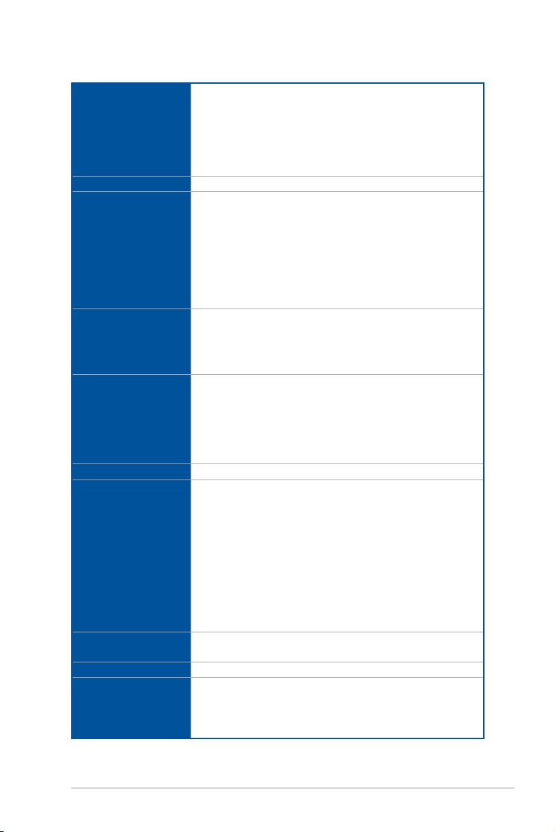
ROG STRIX Z490-A GAMING specifications summary
Intel® Socket LGA 1200 for 10th Gen Intel® Core™, Pentium® Gold and
Celeron® processors*
CPU
Chipset
Memory
Graphics
Expansion Slots
Multi-GPU support
Storage
Ethernet
Wireless & Bluetooth
USB
Supports Intel® 14 nm CPU
Supports Intel® Turbo Boost Technology 2.0 and Intel® Turbo Boost Max
Technology 3.0**
* Refer to www.asus.com for CPU support list.
** Intel® Turbo Boost Max Technology 3.0 support depends on the CPU types.
Intel® Z490 Chipset
4 x DIMM, Max. 128GB, DDR4 4600(O.C) / 4266(O.C.) / 4133(O.C.) /
4000(O.C.) / 3866(O.C.) / 3733(O.C.) / 3600(O.C.) / 3466(O.C.) /
3400(O.C.) / 3200(O.C.) / 3000(O.C.) / 2933(O.C.) / 2800(O.C.) /
2666 / 2400 / 2133 MHz Non-ECC, Un-buffered Memory*
Dual Channel Memory Architecture
Supports Intel® Extreme Memory Profile (XMP)
OptiMem II
* 10th Gen Intel® Core™ i9/i7 CPUs support 2933/2800/2666/2400/2133 natively.
Refer to www.asus.com for the Memory QVL (Qualified Vendors Lists).
1 x DisplayPort 1.4*
1 x HDMI™ 1.4b
* Support DisplayPort 1.4 with max. resolution of 4096 x 2304 @60Hz. Please
refer to www.intel.com for any update.
** Graphics specifications may vary between CPU types.
Intel® 10th Gen Processors*
3 x PCIe 3.0 x16 slots (support x16, x8/x4/x4 modes)
Intel® Z490 Chipset
1 x PCIe 3.0 x4 slot (supports x2 mode)
1 x PCIe 3.0 x1 slot
* Support PCIe bifurcation for RAID on CPU function.
Supports AMD 2-Way CrossFireX™ Technology
Total supports 2 x M.2 slots and 6 x SATA 6Gb/s ports
Intel® Z490 Chipset
M.2_1 slot (Key M), type 2242/2260/2280/22110
(supports PCIe 3.0 x4 & SATA modes)*
M.2_2 slot (Key M), type 2242/2260/2280/22110
(supports PCIe 3.0 x4)
6 x SATA 6Gb/s ports*
Intel® Rapid Storage Technology supports Raid 0,1,5,10
Intel® Optane™ Memory Ready
* M.2_1 shares bandwidth with SATA6G_2. When M.2_1 is populated
SATA6G_2 will be disabled.
1 x Intel® I225-V Ethernet
ASUS LANGuard
M.2 slot (Key E) (Wi-Fi module is sold separately)
Rear USB (Total 8 ports)
2 x USB 3.2 Gen 2 ports (1 x Type-A + 1 x USB Type-C®)
4 x USB 3.2 Gen 1 ports (4 x Type-A)
2 x USB 2.0 ports (Type-A)
(continued on the next page)
vii
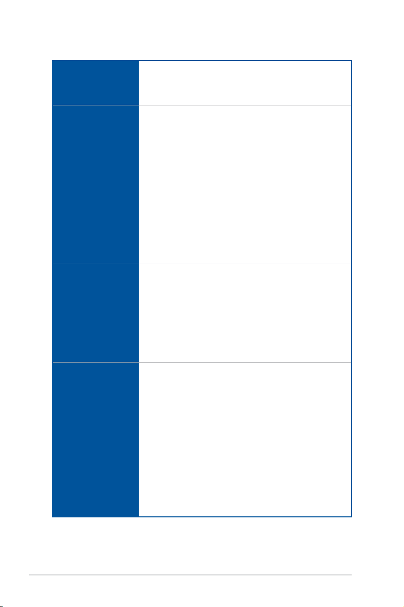
ROG STRIX Z490-A GAMING specifications summary
Front USB (Total 7 ports)
USB
Audio
Back Panel I/O Ports
Internal I/O connectors
1 x USB 3.2 Gen 1 front panel connector (supports USB Type-C®)
1 x USB 3.2 Gen 1 header supports additional 2 USB 3.2 Gen 1 ports
2 x USB 2.0 headers support additional 4 USB 2.0 ports
ROG SupremeFX 8-Channel High Definition Audio CODEC S1220A
- Impedance sense for front and rear headphone outputs
- Jack-detection, Multi-streaming, Front Panel Jack-retasking
- High quality 120 dB SNR stereo playback output and 113 dB SNR
recording input
- Supports up to 32-Bit/192kHz playback*
Audio Features:
- Dual OP Amplifiers
- SupremeFX Shielding Technology
- Gold-plated audio jacks
- Rear optical S/PDIF out port
- Premium Japanese audio capacitors
- Audio Cover
* Due to limitations in HDA bandwidth, 32-Bit/192kHz is not supported for
8-Channel audio.
2 x USB 3.2 Gen 2 ports (1 x Type-A + 1 x USB Type-C®)
4 x USB 3.2 Gen 1 ports (4 x Type-A)
2 x USB 2.0 ports (Type-A)
1 x DisplayPort
1 x HDMI™ port
1 x Intel® I225-V Ethernet port
5 x Gold-plated audio jacks
1 x Optical S/PDIF out port
1 x BIOS FlashBack™ button
Fan and cooling related
1 x 4-Pin CPU Fan header
1 x 4-Pin CPU OPT Fan header
1 x 4-Pin AIO Pump header
2 x 4-Pin Chassis Fan headers
1 x 4-Pin M.2 Fan header
1 x VRM Heatsink Fan header
Power related
1 x 24-pin Main Power connector
1 x 8-pin +12V Power connector
1 x 4-pin +12V Power connector
Storage related
2 x M.2 slots (Key M)
6 x SATA 6Gb/s ports
(continued on the next page)
viii

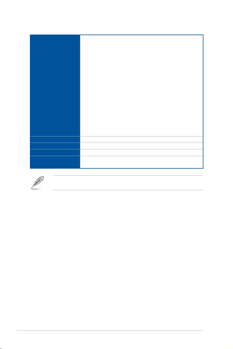
ROG STRIX Z490-A GAMING specifications summary
USB
1 x USB 3.2 Gen 1 front panel connector (supports USB Type-C®)
1 x USB 3.2 Gen 1 header supports additional 2 USB 3.2 Gen 1 ports
2 x USB 2.0 headers support additional 4 USB 2.0 ports
Miscellaneous
1 x AURA Addressable Gen 2 header
Internal I/O connectors
Special Features
Software Features
2 x AURA RGB headers
1 x Clear CMOS header
1 x CPU Over Voltage jumper
1 x Front Panel Audio header (AAFP)
1 x M.2 slot (Key E)
1 x 20-3 pin System Panel header with Chassis intrude function
1 x Thermal Sensor header
1 x Thunderbolt header
Aura Feature
- Standard RGB headers
- Addressable Gen 2 RGB header
ASUS Q-Design
- ASUS Q-DIMM
- ASUS Q-LED (CPU [red], DRAM [yellow], VGA [white], Boot Device
[yellow green])
- ASUS Q-Slot
ASUS Thermal Solution
- Aluminum M.2 heatsink
ASUS EZ DIY
- BIOS FlashBack™ button
- BIOS FlashBack™ LED
- Procool II
- Pre-mounted I/O Shield
- SafeSlot
ROG Exclusive Software
- RAMCache III
- ROG CPU-Z
- GameFirst VI
- Sonic Studio III + Sonic Studio Virtual Mixer
- Sonic Radar III
- DTS® Sound Unbound
- Overwolf
- Anti-virus software
ASUS Exclusive Software Features
Armoury Crate
- Aura Creator
- Aura Sync
(continued on the next page)
ix
ROG STRIX Z490-A GAMING specifications summary
AI Suite 3
- 5-Way Optimization with AI Overclocking
TPU
EPU
DIGI+ VRM
Fan Xpert 4
Turbo APP
Software Features
BIOS
Manageability
Operating System
Form Factor
Specifications are subject to change without notice. Please refer to the ASUS website for
the latest specifications.
- EZ update
WinRAR
UEFI BIOS
AI Overclocking
ASUS EZ DIY
- ASUS CrashFree BIOS 3
- ASUS EZ Flash 3
- ASUS UEFI BIOS EZ Mode
FlexKey
192 (128+64) Mb Flash ROM, UEFI AMI BIOS
WOL by PME, PXE
Windows® 10 - 64 bit
ATX Form Factor
12 inch x 9.6 inch (30.5 cm x 24.4 cm)
x
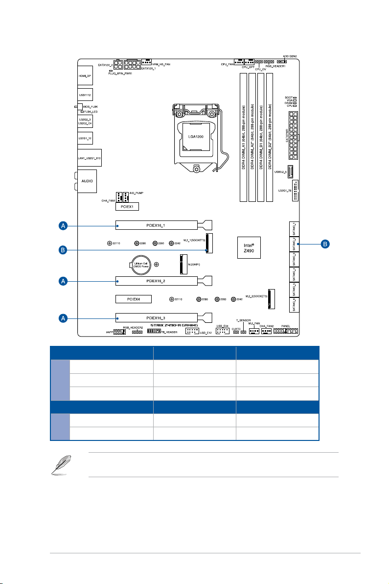
Connectors with shared bandwidth
Configuration 1 2
PCIEX16_1 x16 x8
PCIEX16_2 - x4
A
PCIEX16_3 - x4
Configuration 1 2
M.2_1 x4 -
B
SATA6G_2 - V
M.2_1 shares bandwidth with SATA6G_2. When M.2_1 is populated SATA6G_2 will be
disabled.
xi

Package contents
Check your motherboard package for the following items.
Motherboard 1 x ROG STRIX Z490-A GAMING motherboard
1 x Addressable RGB extension cable
Cables
ROG Additional Cooling Kit 1 x Fan bracket
Miscellaneous
Installation Media 1 x Support DVD
Documentation 1 x User manual
If any of the above items is damaged or missing, contact your retailer.
1 x RGB extension cable
4 x SATA 6Gb/s cables
1 x Thermistor cable pack
1 x Cable ties pack
1 x M.2 Rubber Package
1 x M.2 SSD screw package
1 x M.2 Key E screw package
1 x ROG Strix stickers
1 x ROG Strix thank you card
xii
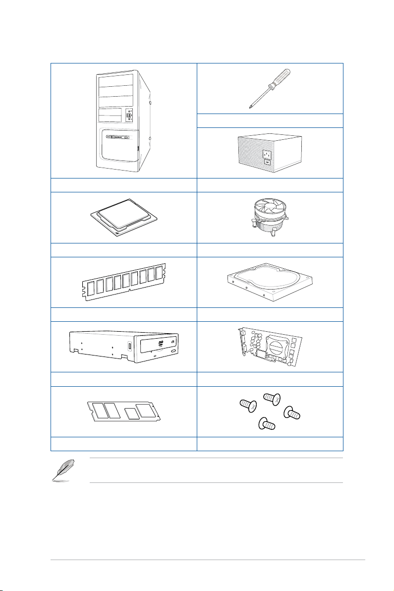
Installation tools and components
Phillips (cross) screwdriver
PC chassis Power supply unit
Intel® LGA 1200 CPU Intel® LGA 1200 compatible CPU Fan
DDR4 DIMM SATA hard disk drive
SATA optical disc drive (optional) Graphics card (optional)
M.2 SSD module (optional) 1 Bag of screws
The tools and components in the table above are not included in the motherboard
package.
xiii

xiv

Chapter 1: Product Introduction
Product Introduction
1
1.1 Before you proceed
Take note of the following precautions before you install motherboard components or
change any motherboard settings.
• Unplug the power cord from the wall socket before touching any component.
• Before handling components, use a grounded wrist strap or touch a safely grounded
object or a metal object, such as the power supply case, to avoid damaging them due
to static electricity.
• Hold components by the edges to avoid touching the ICs on them.
• Whenever you uninstall any component, place it on a grounded antistatic pad or in
the bag that came with the component.
• Before you install or remove any component, ensure that the ATX power supply is
switched off or the power cord is detached from the power supply. Failure to do so
may cause severe damage to the motherboard, peripherals, or components.
Chapter 1
ROG STRIX Z490-A GAMING
1-1
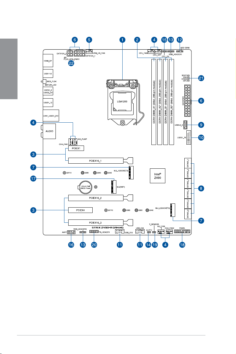
1.2 Motherboard layout
Chapter 1
1-2
Chapter 1: Product Introduction
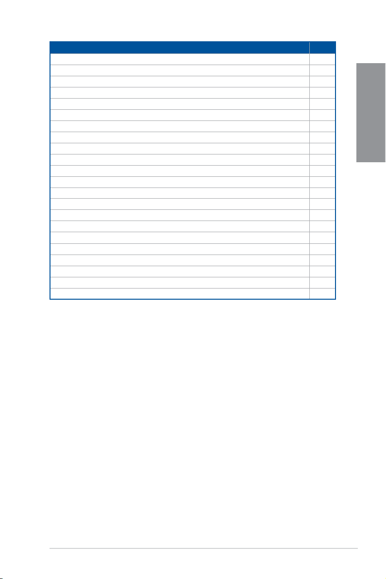
Layout contents Page
1. CPU socket 1-4
2. DIMM slots 1-5
3. Expansion slots 1-7
4. Fan and Pump headers 1-9
5. VRM Heatsink Fan header 1-10
6. Power connectors 1-11
7. M.2 slot 1-12
8. SATA 6GB/s port 1-13
9. USB 3.2 Gen 1 Front Panel connector 1-14
10. USB 3.2 Gen 1 header 1-14
11. USB 2.0 header 1-15
12. AURA Addressable Gen2 header 1-16
13. AURA RGB header 1-17
14. Clear CMOS header 1-18
15. CPU Over Voltage jumper 1-19
16. Front Panel Audio header 1-19
17. M.2 slot (Key E)
18. System Panel header 1-21
19. Thermal Sensor header 1-22
20. Thunderbolt header 1-23
21. Q-LEDs 1-24
22. 8-pin Power Plug LED 1-24
1-20
Chapter 1
ROG STRIX Z490-A GAMING
1-3
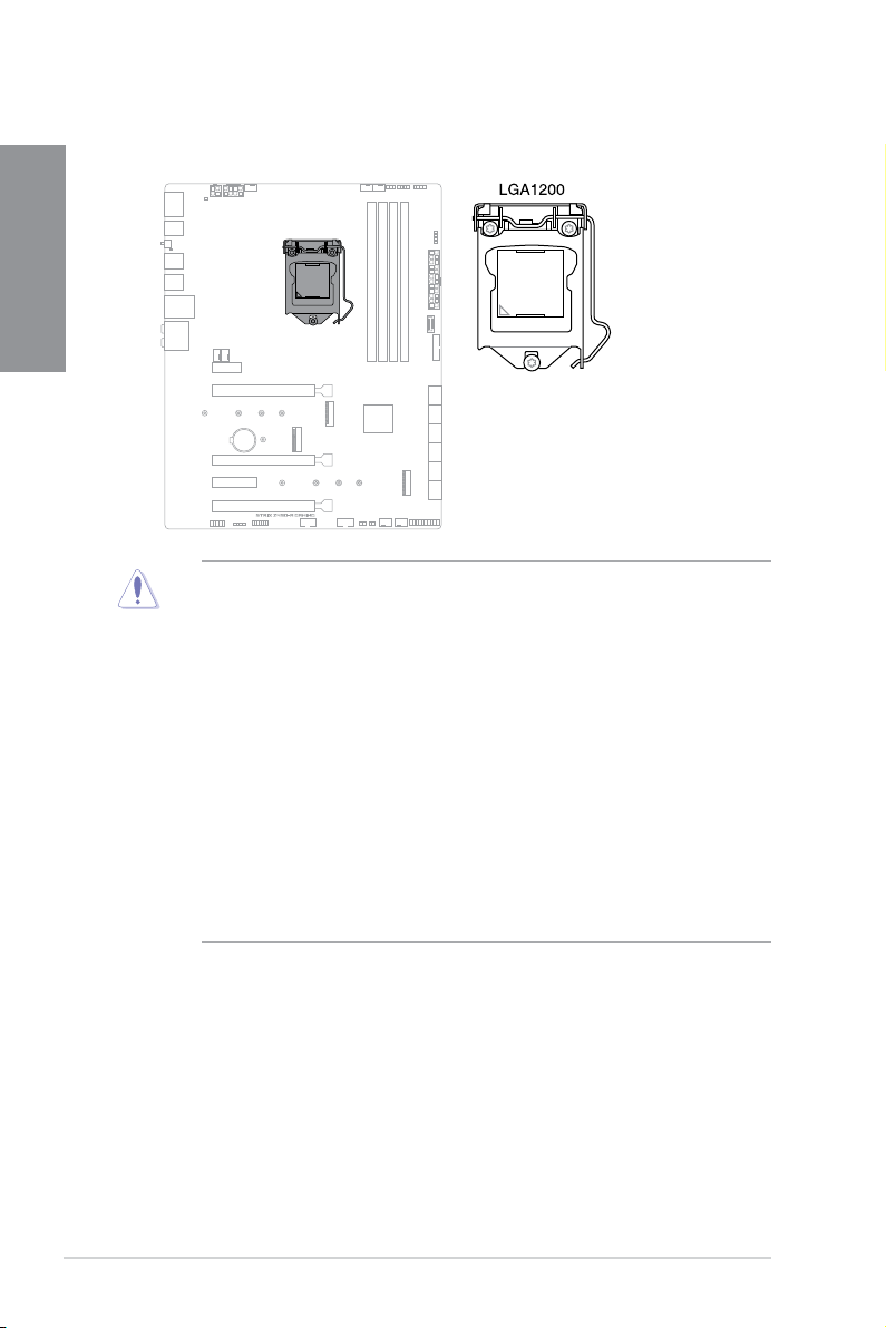
1. CPU socket
The motherboard comes with a LGA1200 socket designed for 10th Gen Intel® Core™,
Pentium® Gold and Celeron® processors.
Chapter 1
• Ensure that you install the correct CPU designed for LGA1200 socket only. DO NOT
install a CPU designed for other sockets on the LGA1200 socket.
• The CPU fits in only one correct orientation. DO NOT force the CPU into the socket
to prevent bending the connectors on the socket and damaging the CPU.
• Ensure that all power cables are unplugged before installing the CPU.
• Upon purchase of the motherboard, ensure that the PnP cap is on the socket and
the socket contacts are not bent. Contact your retailer immediately if the PnP cap
is missing, or if you see any damage to the PnP cap/socket contacts/motherboard
components. ASUS will shoulder the cost of repair only if the damage is shipment/
transit-related.
• Keep the cap after installing the motherboard. ASUS will process Return
Merchandise Authorization (RMA) requests only if the motherboard comes with the
cap on the LGA1200 socket.
• The product warranty does not cover damage to the socket contacts resulting from
incorrect CPU installation/removal, or misplacement/loss/incorrect removal of the
PnP cap.
1-4
Chapter 1: Product Introduction
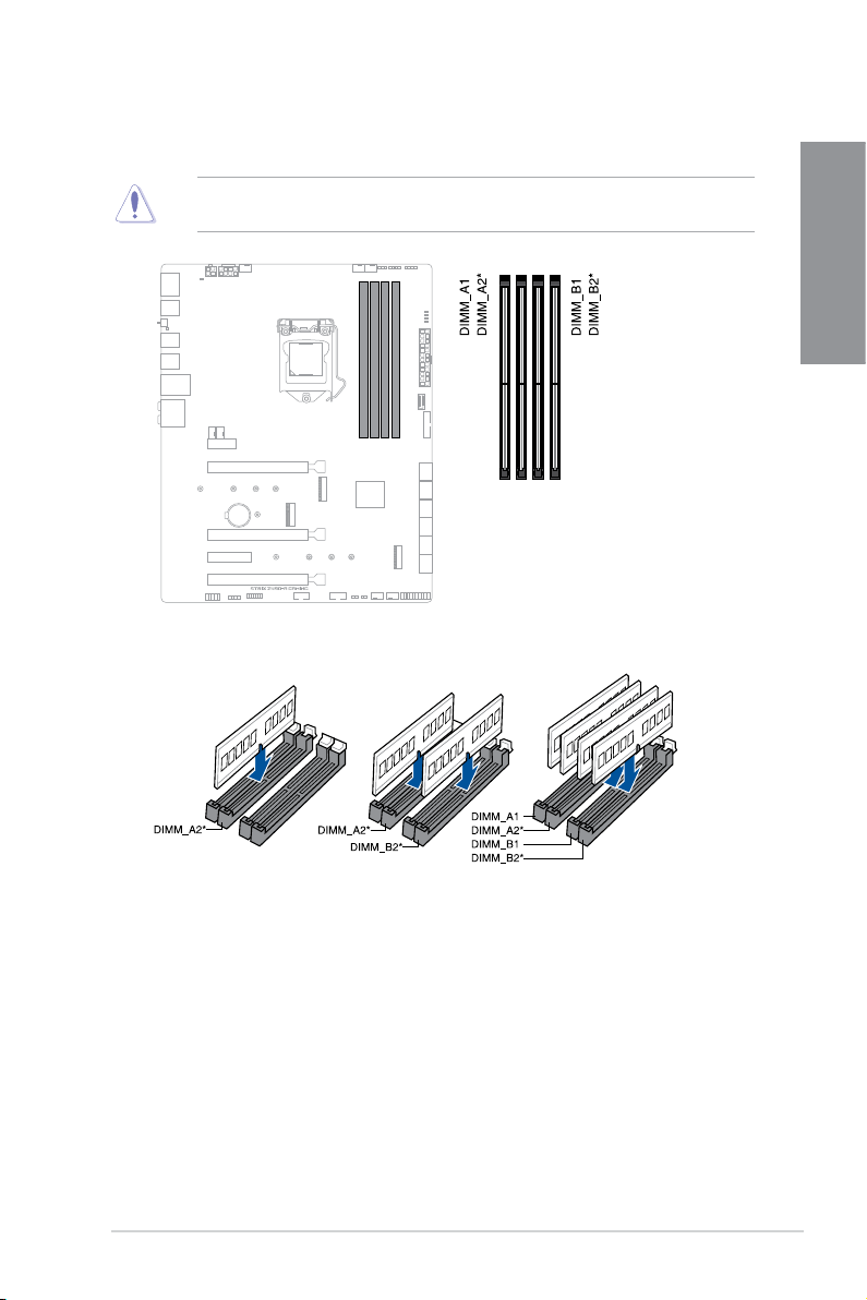
2. DIMM slots
The motherboard comes with Dual Inline Memory Modules (DIMM) slots designed for DDR4
(Double Data Rate 4) memory modules.
A DDR4 memory module is notched differently from a DDR, DDR2, or DDR3 module. DO
NOT install a DDR, DDR2, or DDR3 memory module to the DDR4 slot.
Recommended memory configurations
Chapter 1
ROG STRIX Z490-A GAMING
1-5

Memory configurations
You may install 4 GB, 8 GB, 16 GB, and 32 GB unbuffered and non-ECC DDR4 DIMMs into
the DIMM sockets.
Chapter 1
You may install varying memory sizes in Channel A and Channel B. The system maps
the total size of the lower-sized channel for the dual-channel configuration. Any excess
memory from the higher-sized channel is then mapped for single-channel operation.
• The default memory operation frequency is dependent on its Serial Presence Detect
(SPD), which is the standard way of accessing information from a memory module.
Under the default state, some memory modules for overclocking may operate at a
lower frequency than the vendor-marked value.
• For system stability, use a more efficient memory cooling system to support a full
memory load or overclocking condition.
• Always install the DIMMS with the same CAS Latency. For an optimum compatibility,
we recommend that you install memory modules of the same version or data code
(D/C) from the same vendor. Check with the vendor to get the correct memory
modules.
• Visit the ASUS website for the latest QVL.
1-6
Chapter 1: Product Introduction
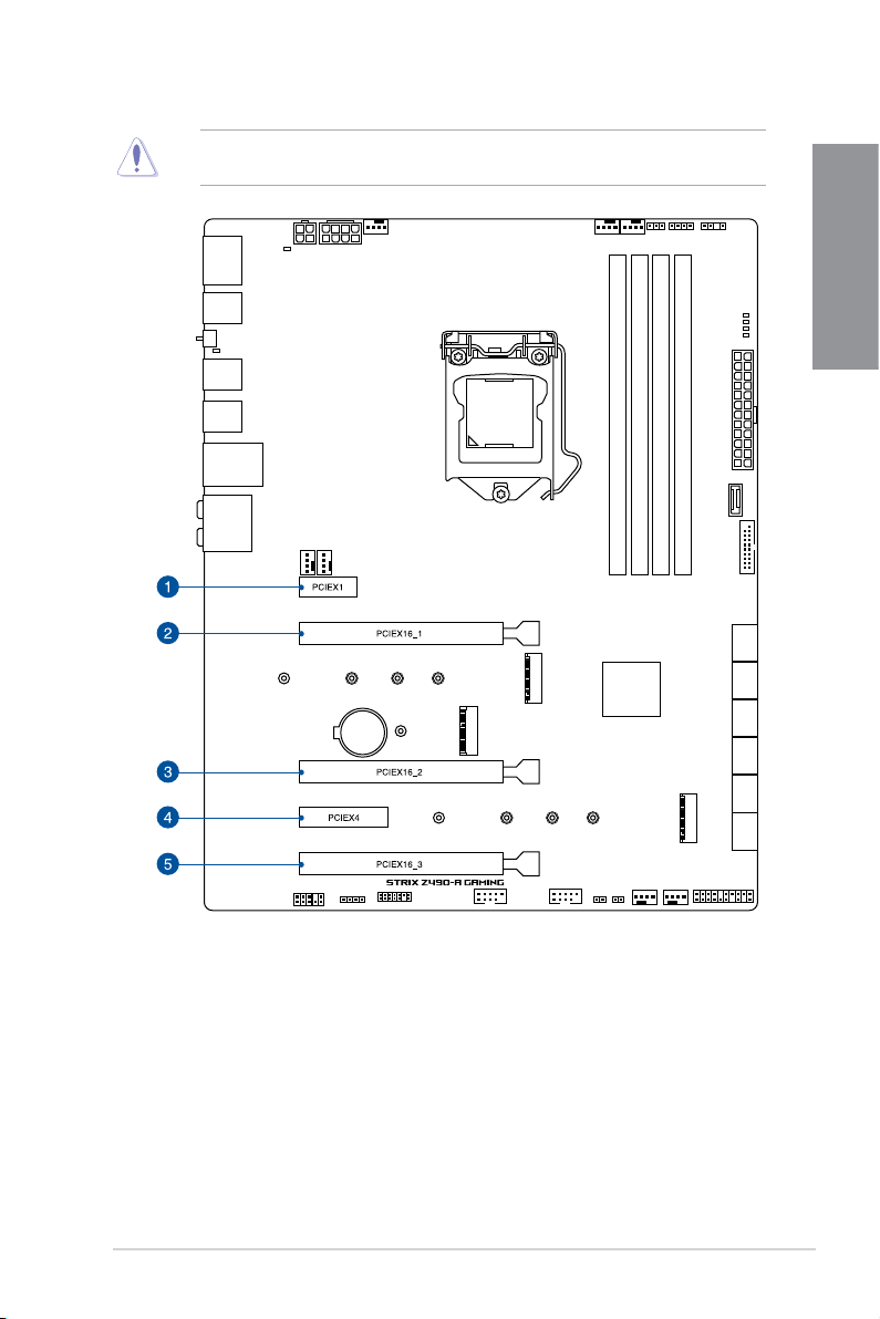
3. Expansion slots
Unplug the power cord before adding or removing expansion cards. Failure to do so may
cause you physical injury and damage motherboard components.
Chapter 1
Please refer to the following tables for the recommended VGA configuration and Hyper M.2
configuration.
ROG STRIX Z490-A GAMING
1-7
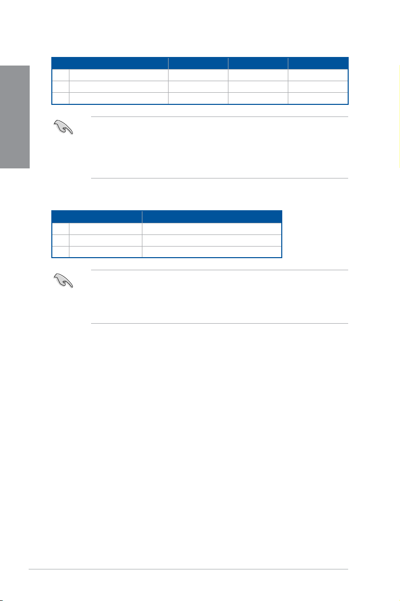
Recommended VGA configuration
Slot Description Single VGA Dual VGA Triple VGA
2. PCIe 3.0 x16_1 x16 x8 x8
Chapter 1
3. PCIe 3.0 x16_2 - x4 x4
5. PCIe 3.0 x16_3 - x4 x4
Hyper M.2 X16 series card configuration
Slot Description Up to 3 Intel® SSD on CPU support
2. PCIe 3.0 x16_1 x8+x4+x4
3. PCIe 3.0 x16_2 -
5. PCIe 3.0 x16_3 -
• We recommend that you provide sufficient power when running CrossFireX™ mode.
• Ensure to connect the 8-pin and 4-pin power plugs when running CrossFireX™
mode.
• Connect a chassis fan to the chassis fan connectors when using multiple graphics
cards for better thermal environment.
• Hyper M.2 X16 series card sold separately.
• When using up to 3 intel® SSD on CPU support, PCIe 3.0 x16_2 and PCIe 3.0 x16_3
will be disabled. If you wish to connect a display, we suggest using the internal VGA.
• Enable the Hyper M.2 X16 series card under BIOS settings.
1-8
Chapter 1: Product Introduction
 Loading...