How it Works
Log In / Sign Up
Buy Points
How it Works
FAQ
Contact Us
Questions and Suggestions
Users
ASUS
Loading...
R
ROG Strix Hero II
ROG Strix Hero II GL504GM-BN328
ROG Strix Hero II GL504GM-BN328T
ROG Strix Hero II GL504GV-ES117
Rog Strix Impact II
ROG Strix LC 120
2
ROG Strix LC 360
ROG Strix LC 360 RGB
ROG Strix OLED XG27UCDMG 26.5"" 3840x2160px 240Hz 0.03 ms [GTG]
ROG Strix Radeon RX 5500 XT
ROG STRIX RTX 2070 8G GAMING
ROG STRIX RTX 2080 8G GAMING
ROG STRIX RTX 2080TI 11G GAMING
ROG Strix Scar
ROG Strix Scar 17 G732LXS-HG014T
2
ROG Strix SCAR Edition GL503GE-EN272
ROG Strix SCAR Edition GL503GE-EN272T
ROG Strix SCAR Edition GL703GE-EE197T
ROG Strix SCAR Edition GL703GE-GC075T
ROG Strix Scar G533QS-HF212T
ROG Strix Scar G533ZS-LN025W
ROG Strix Scar G533ZW
ROG Strix Scar G533ZX-HF044
ROG Strix Scar G533ZX-LN045W
ROG Strix Scar G733ZW-KH126W
ROG Strix Scar G733ZW-LL125W
ROG Strix Scar G733ZX-KH012
ROG Strix SCAR II GL504GM-ES329T
ROG Strix Scar II GL504GS-ES088T
ROG Strix Scar II GL504GV-ES105T
ROG Strix Scar II GL504GV-ES106T
ROG Strix Scar II GL504GV-ES112
ROG Strix Scar II GL504GV-ES112T
ROG Strix Scar II GL504GV-ES143T
ROG Strix Scar II GL504GW-ES057T
ROG Strix Scar II GL504GW-ES058T
ROG Strix SCAR II GL504GW-ES076T
ROG Strix SCAR II GL704GW-EV043T
ROG Strix Scope
2
ROG Strix Scope Deluxe
ROG Strix Scope II 96 Wireless
ROG Strix Scope RX
2
ROG Strix SE G733CW-LL013W
ROG STRIX TRX40-E GAMING
ROG Strix TRX40-XE Gaming
2
ROG Strix Wireless
ROG Strix X299-E Gaming
2
ROG STRIX X299-E GAMING II
2
ROG Strix X299-XE Gaming
2
ROG Strix X370-F Gaming
ROG Strix X399-E Gaming
ROG Strix X470-F Gaming
2
ROG Strix X470-I Gaming
ROG Strix X570-E Gaming
Rog Strix X570-E Gaming WiFi II
ROG Strix X570-F Gaming
ROG STRIX XG17AHP
4
ROG STRIX XG17AHPE
3
ROG Strix XG248Q
2
ROG STRIX XG258Q
3
ROG Strix XG259CM
ROG Strix XG259CMS 24.5"" 1920x1080px IPS 310Hz 1 ms [GTG]
ROG Strix XG259QN 24.5"" 1920x1080px IPS 380Hz 0.3 ms [GTG]
ROG Strix XG259QNS 24.5"" 1920x1080px IPS 380Hz 0.3 ms [GTG]
ROG Strix XG279Q
2
ROG Strix XG27ACG 27"" 2560x1440px IPS 180Hz 1 ms [GTG]
ROG Strix XG27ACMG 27"" 2560x1440px IPS 270Hz 1ms [GTG]
ROG Strix XG27ACS 27"" 2560x1440px IPS 180Hz 1 ms [GTG]
ROG Strix XG27ACS-W 27"" 2560x1440px IPS 180Hz 1 ms [GTG]
ROG Strix XG27AQ
Rog Strix XG27AQM
ROG Strix XG27AQMR 27"" 2560x1440px IPS 300Hz 1 ms [GTG]
ROG Strix XG27UCS 27"" 3840x2160px IPS 160Hz 1 ms [GTG]
ROG Strix XG27UQ
2
ROG Strix XG27UQR
ROG Strix XG27VQ
3
ROG Strix XG27WCMS 27"" 2560x1440px 280Hz 1ms [GTG] Curved
ROG Strix XG27WCS 27"" 2560x1440px 180Hz 1 ms [GTG] Curved
ROG Strix XG27WQ
3
ROG Strix XG309CM 29.5"" 2560x1080px IPS 220Hz 1 ms
ROG Strix XG32AQ
ROG Strix XG32UQ
ROG Strix XG32VC
ROG Strix XG32VQ
2
ROG Strix XG32VQR
ROG Strix XG32WCMS 31.5"" 2560x1440px 280Hz 1 ms [GTG] Curved
ROG Strix XG32WCS 31.5"" 2560x1440px 180Hz 1 ms [GTG] Curved
ROG Strix XG349C 34.14"" 3440x1440px IPS 180Hz 1 ms [GTG] Curved
ROG Strix XG349C 34,1tm
ROG Strix XG35VQ
ROG Strix XG438Q
ROG Strix XG438QR
ROG Strix XG43VQ
2
ROG Strix XG49VQ
4
ROG Strix XG49WCR 49"" 5120x1440px 165Hz 1 ms [MPRT] Curved
ROG STRIX Z200
ROG STRIX Z370-E GAMING
ROG Strix Z370-F Gaming
ROG STRIX Z370-H GAMING
ROG Strix Z370-I Gaming
Loading...
Loading...
Nothing found
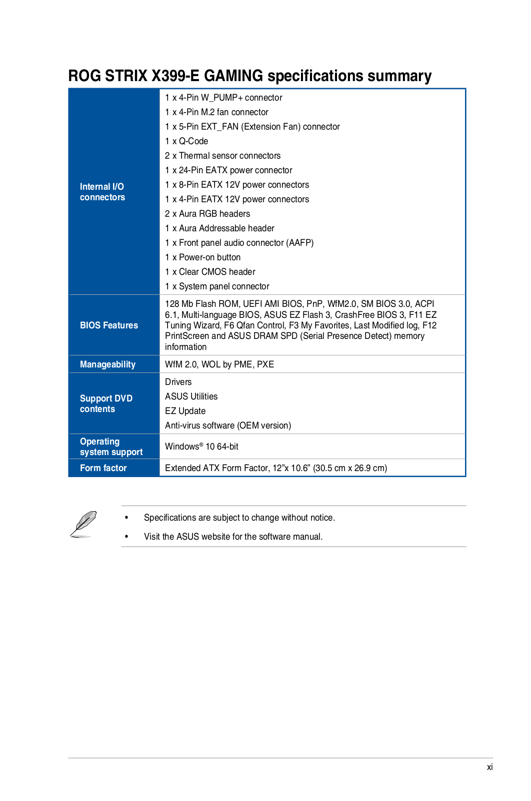
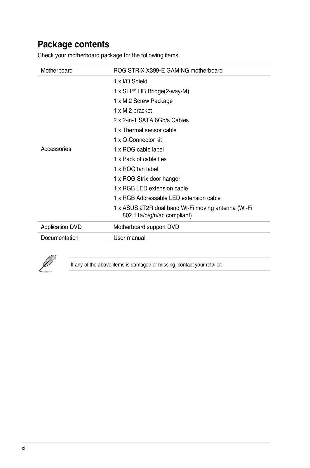
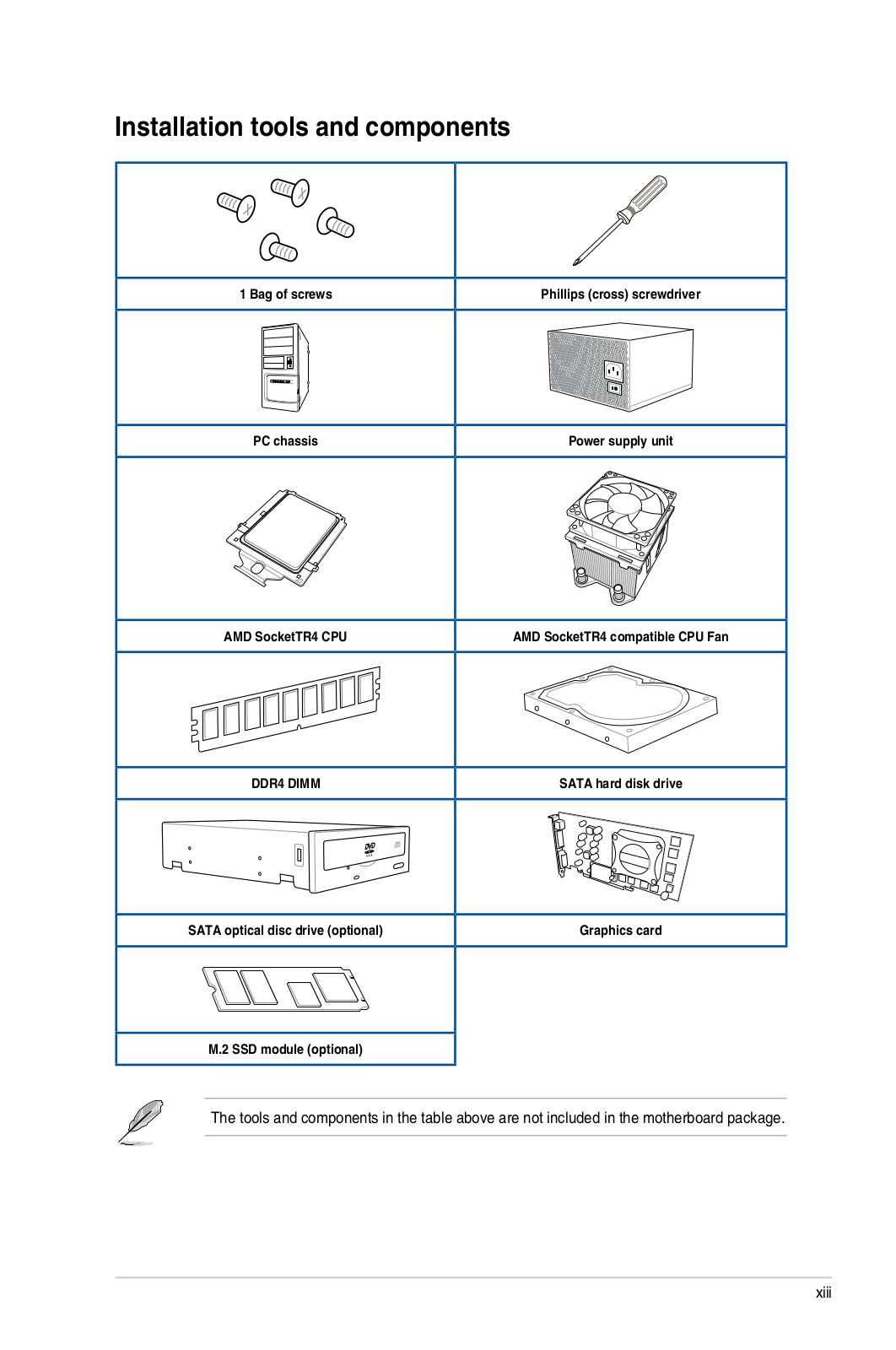
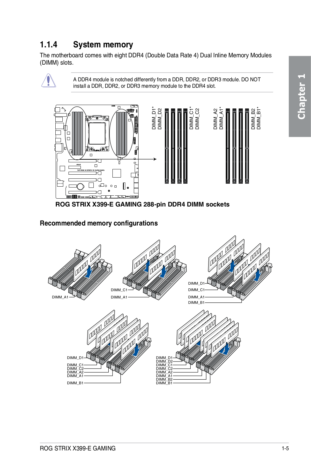
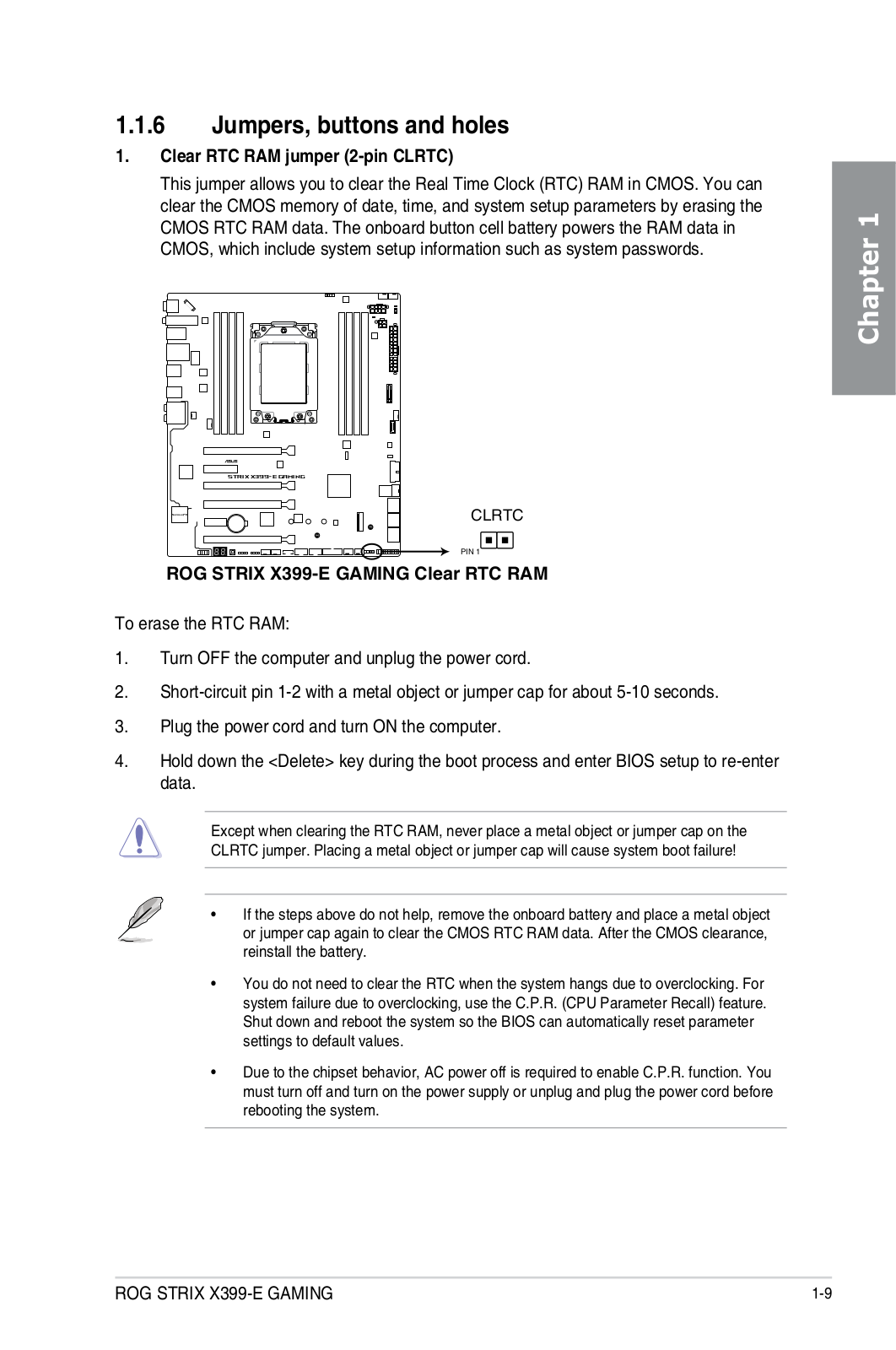
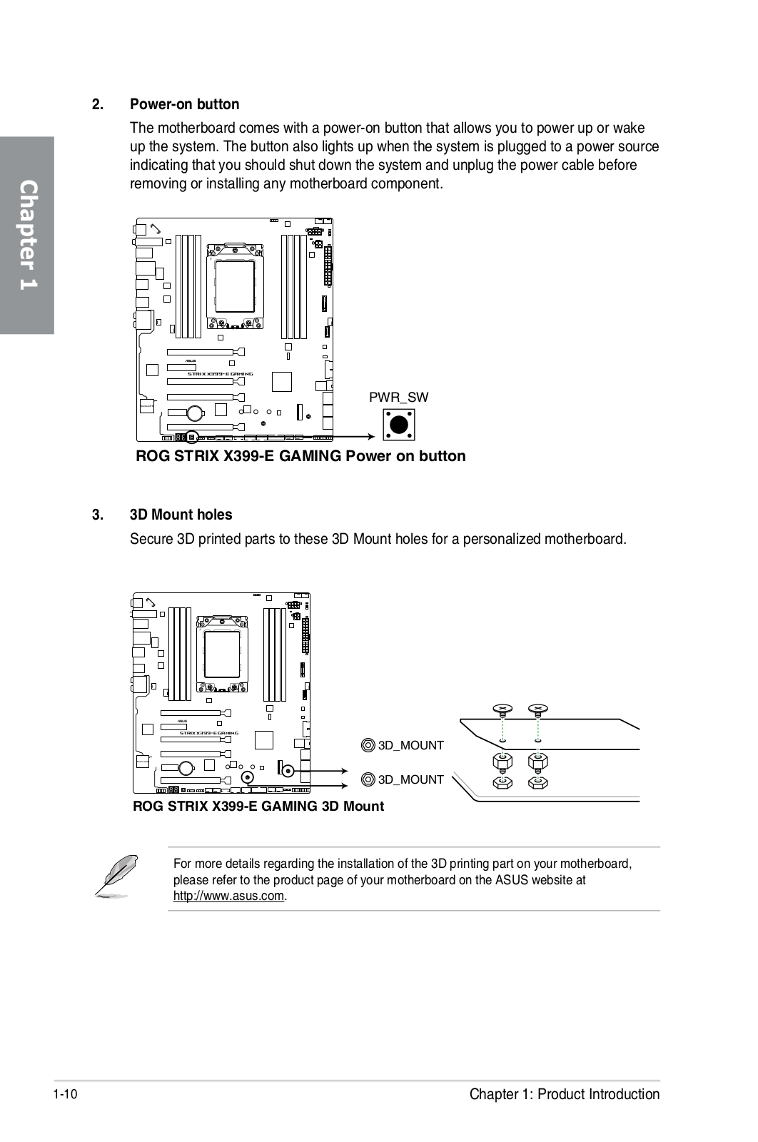
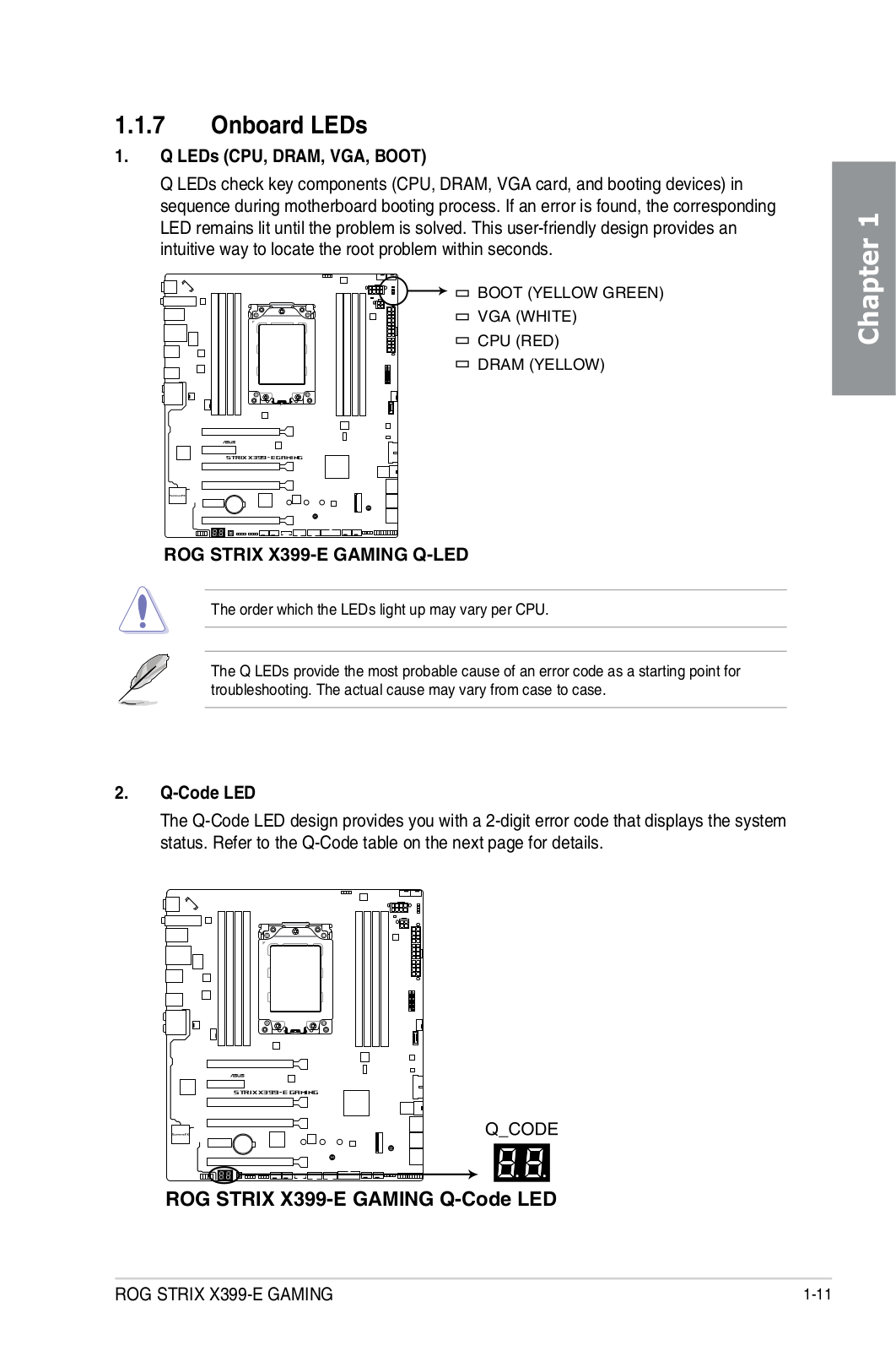
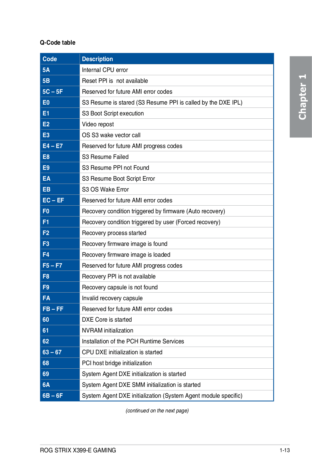
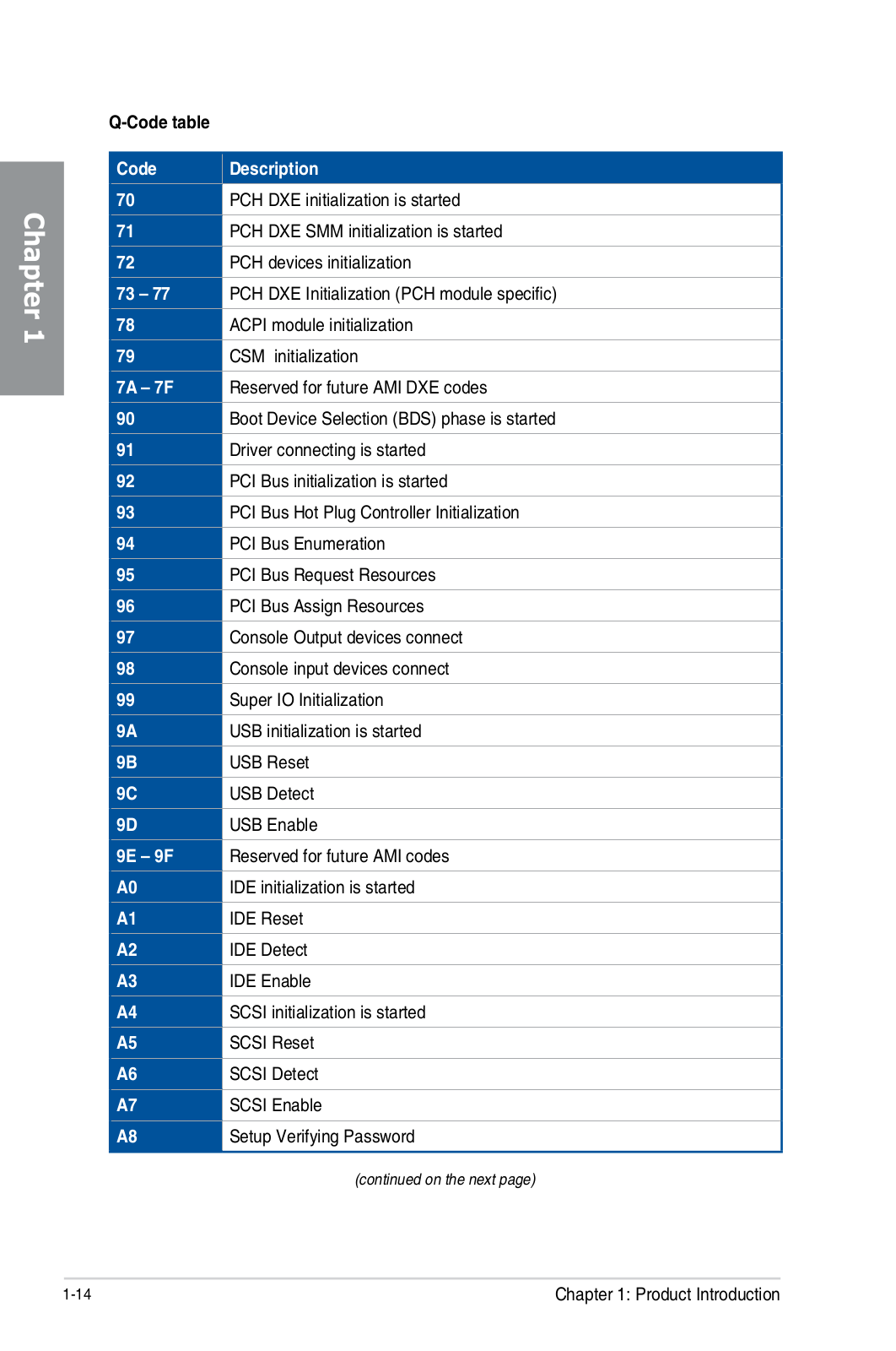
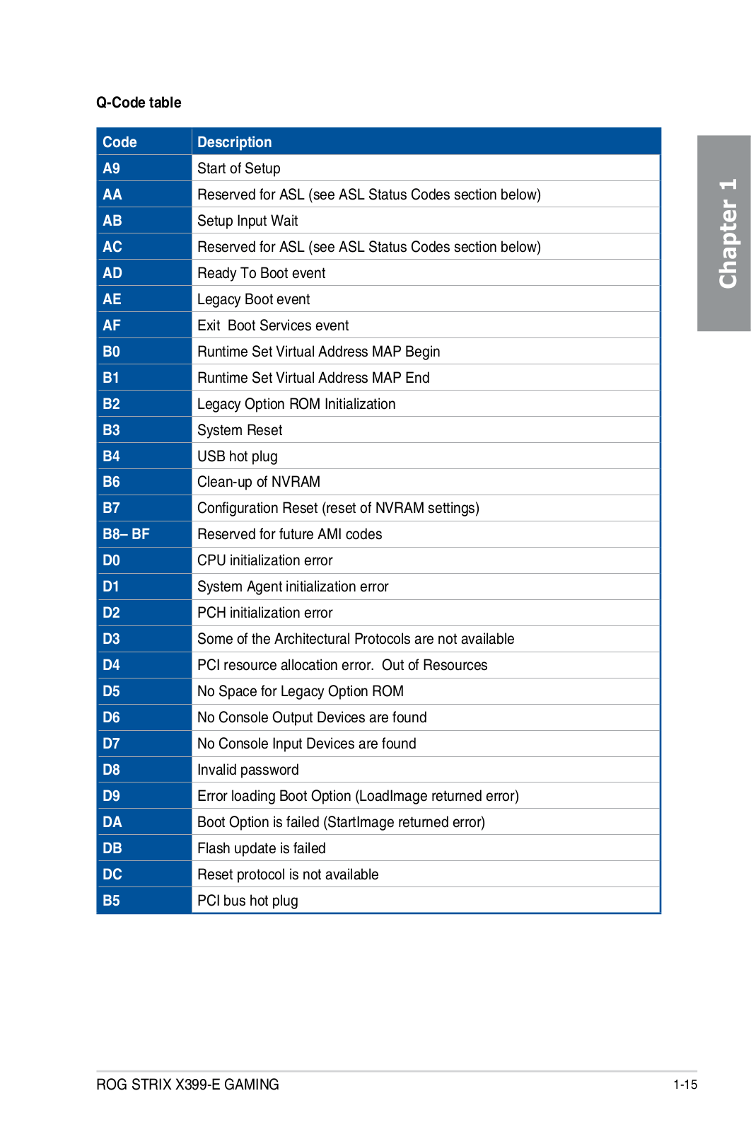
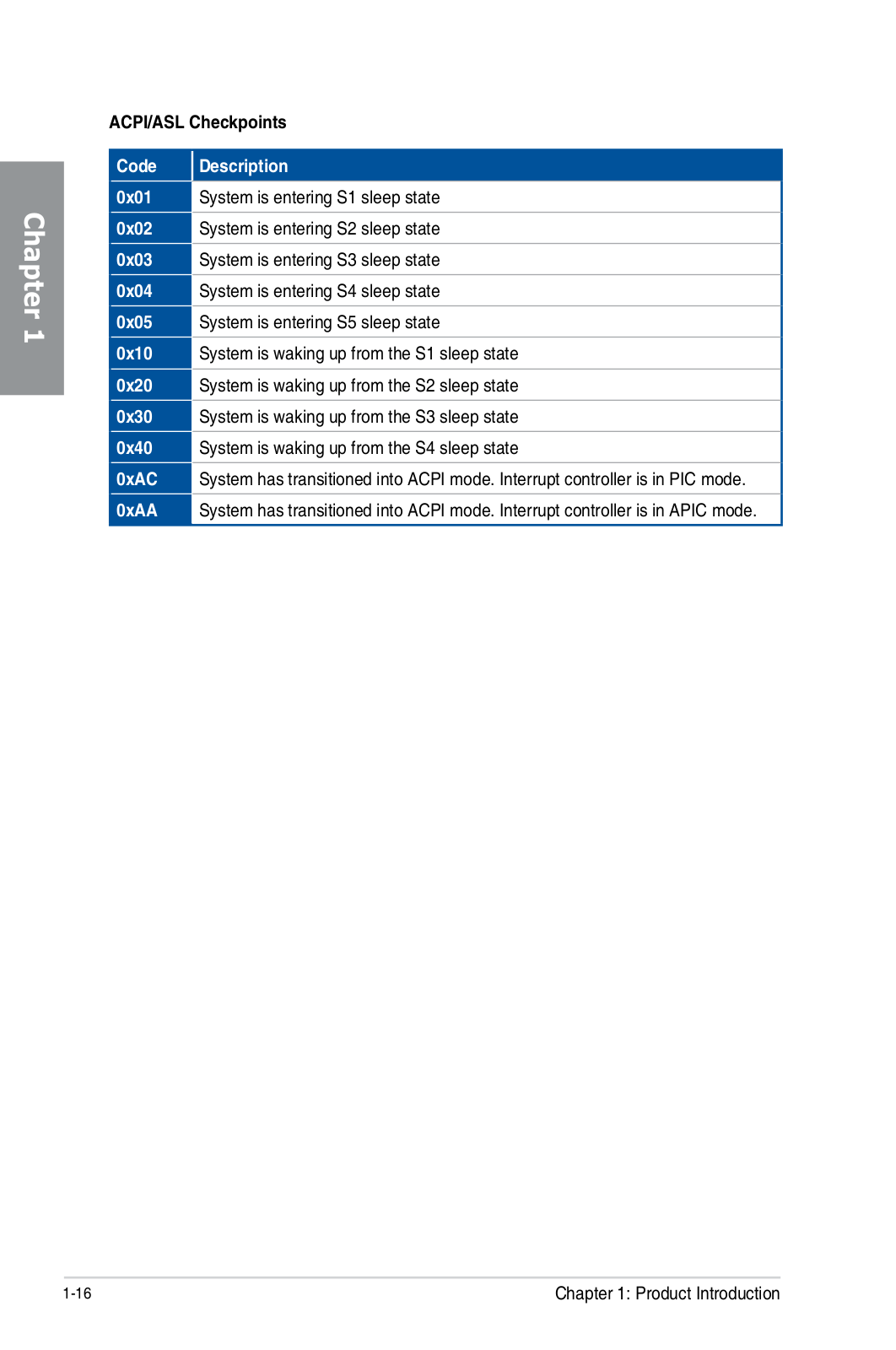
ROG Strix X399-E Gaming
Service Manual
100 pgs
5.87 Mb
0
Table of contents
Loading...
ASUS ROG Strix X399-E Gaming Service Manual
...
ASUS Service Manual
Download
Specifications and Main Features
Frequently Asked Questions
User Manual
Download
Loading...
+
hidden pages
Unhide
You need points to download manuals.
1 point = 1 manual.
You can buy points or you can get point for every manual you upload.
Buy points
Upload your manuals
 Loading...