


Q170A-IM-A
Industrial Motherboard

E17978
First Edition
March 2021
Copyright © 2021 ASUSTeK COMPUTER INC. All Rights Reserved.
No part of this manual, including the products and software described in it, may be reproduced,
transmitted, transcribed, stored in a retrieval system, or translated into any language in any form or by any
means, except documentation kept by the purchaser for backup purposes, without the express written
permission of ASUSTeK COMPUTER INC. (“ASUS”).
Product warranty or service will not be extended if: (1) the product is repaired, modied or altered, unless
such repair, modication of alteration is authorized in writing by ASUS; or (2) the serial number of the
product is defaced or missing.
ASUS PROVIDES THIS MANUAL “AS IS” WITHOUT WARRANTY OF ANY KIND, EITHER EXPRESS
OR IMPLIED, INCLUDING BUT NOT LIMITED TO THE IMPLIED WARRANTIES OR CONDITIONS OF
MERCHANTABILITY OR FITNESS FOR A PARTICULAR PURPOSE. IN NO EVENT SHALL ASUS, ITS
DIRECTORS, OFFICERS, EMPLOYEES OR AGENTS BE LIABLE FOR ANY INDIRECT, SPECIAL,
INCIDENTAL, OR CONSEQUENTIAL DAMAGES (INCLUDING DAMAGES FOR LOSS OF PROFITS,
LOSS OF BUSINESS, LOSS OF USE OR DATA, INTERRUPTION OF BUSINESS AND THE LIKE),
EVEN IF ASUS HAS BEEN ADVISED OF THE POSSIBILITY OF SUCH DAMAGES ARISING FROM ANY
DEFECT OR ERROR IN THIS MANUAL OR PRODUCT.
SPECIFICATIONS AND INFORMATION CONTAINED IN THIS MANUAL ARE FURNISHED FOR
INFORMATIONAL USE ONLY, AND ARE SUBJECT TO CHANGE AT ANY TIME WITHOUT NOTICE,
AND SHOULD NOT BE CONSTRUED AS A COMMITMENT BY ASUS. ASUS ASSUMES NO
RESPONSIBILITY OR LIABILITY FOR ANY ERRORS OR INACCURACIES THAT MAY APPEAR IN THIS
MANUAL, INCLUDING THE PRODUCTS AND SOFTWARE DESCRIBED IN IT.
Products and corporate names appearing in this manual may or may not be registered trademarks or
copyrights of their respective companies, and are used only for identication or explanation and to the
owners’ benet, without intent to infringe.
ii

Contents
Chapter 1 Product overview
1.1 Package contents......................................................................... 1-1
1.2 Features ........................................................................................ 1-1
1.3 Specifications ............................................................................... 1-2
Chapter 2 Motherboard information
2.1 Before you proceed ..................................................................... 2-1
2.2 Motherboard layout ...................................................................... 2-2
2.3 Central Processing Unit (CPU) ................................................... 2-4
2.3.1 Installing the CPU ........................................................... 2-5
2.3.2 CPU heatsink and fan assembly installation ................... 2-7
2.4 System memory ........................................................................... 2-9
2.5 Jumpers ...................................................................................... 2-11
2.6 Connectors ................................................................................. 2-14
2.6.1 Rear panel connectors .................................................. 2-14
2.6.2 Internal connectors ....................................................... 2-16
Chapter 3 BIOS setup
3.1 BIOS Setup program .................................................................... 3-1
3.1.1 BIOS menu screen .......................................................... 3-2
3.2 Main menu .................................................................................... 3-2
3.2.1 System Date [Day MM/DD/YYYY] .................................. 3-2
3.2.2 System Time [HH:MM:SS] .............................................. 3-2
3.3 Advanced menu ........................................................................... 3-2
3.3.1 PCH-FW Conguration ................................................... 3-2
3.3.2 Trusted Computing ......................................................... 3-2
3.3.3 CPU Conguration .......................................................... 3-3
3.3.4 Graphics Conguration ................................................... 3-4
3.3.5 PCI Express Conguration .............................................. 3-4
3.3.6 CSM Conguration .......................................................... 3-7
3.3.7 Super IO Conguration ................................................... 3-7
3.3.8 Serial Console Conguration .......................................... 3-9
3.3.9 SATA Conguration ........................................................ 3-9
3.3.10 USB Conguration .......................................................... 3-9
3.3.11 Onboard Devices Conguration ...................................... 3-9
3.3.12 APM Conguration ........................................................ 3-10
iii

3.3.13 EzFlash ......................................................................... 3-11
3.3.14 Watchdog Timer ............................................................ 3-11
3.3.15 Network Stack Conguration ........................................ 3-11
3.3.16 Miscellaneous ............................................................... 3-11
3.4 Hardware Monitor menu ............................................................ 3-12
3.5 Security menu ............................................................................ 3-12
3.6 Boot menu .................................................................................. 3-14
3.7 Exit menu .................................................................................... 3-16
Appendix
Notices .......................................................................................................A-1
Warranty ....................................................................................................A-5
ASUS contact information .......................................................................A-7
iv
Chapter 1
Product overview
1.1 Package contents
Check your industrial motherboard package for the following items.
1 x ASUS Q170A-IM-A Industrial Motherboard
1 x SATA 6.0 Gb/s cable
1 x M.2 screw package
1 x ASUS I/O shield
NOTE: If any of the above items is damaged or missing, contact your
distributor or sales representative immediately.
1.2 Features
• Intel® Socket 1151 for 7th/ 6th Generation Core™ i7/ i5/ i3, Pentium®, and
Celeron® Processors
• Two Dual Channel DDR4 2400/2133MHz Non-ECC U-DIMMs up to 32GB
• 3 x SATA 6.0 Gb/s, 4 x USB 3.2 Gen 1, 6 x USB 2.0, 8 x COM ports
• 1 x PCIe x4 slot, 3 x PCIe x16 slots, 3 x PCI slots, 1 x M.2 Socket 3 (Key M,
type 2242/2260/2280, SATA mode)
• Multi-display: 1 x VGA, 1 x HDMI
Chapter 1: General information
1-1
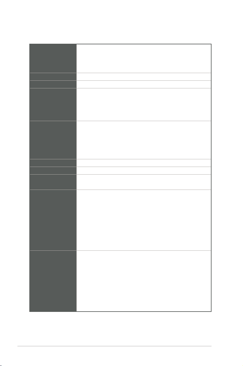
1.3 Specifications
Intel® Socket 1151 for 7th/ 6th Gen Intel® Core™ i7/ i5/ i3, Pentium®,
CPU
Chipset
Memory
Graphics
Expansion slots
Storage
LAN
Audio
Rear I/O ports
Internal I/O
connectors
and Celeron® Processors
Supports Intel® 14nm CPU
Supports up to 65W
Intel® Q170 Chipset
2 x U-DIMM, max.32GB, DDR4 2400/2133 MHz SDRAM
Supports dual displays: 1 x VGA port + 1 x HDMITM port (Default)
- Supports VGA output with a maximum resolution of
1920 x 1200 @60Hz
- Supports HDMI output with a maximum resolution of
4096 x 2160 @24Hz
1 x PCIe 3.0/2.0 x16 slot (x16 mode)
2 x PCIe 3.0/2.0 x16 slots (x4 mode)
1 x PCIe 3.0/2.0 x4 slot
3 x PCI slots
1 x M.2 Socket 3 with M key, type 2242/2260/2280 (SATA mode)
3 x SATA Gen 3.0, up to 6.0 Gb/s ports
Dual Intel® Lan: 1 x Intel® i219V, 1 x Intel® I211AT
Realtek ALC897 High Denition Audio
Line-Out, Line-In, Mic in
1 x VGA port
1 x HDMITM port
4 x USB 3.2 Gen 1 ports
2 x LAN (RJ45) ports
2 x COM ports (RS232/422/485)
1 x P/S2 Keyboard port
1 x P/S2 Mouse port
3 x Audio jacks
1 x AT/ATX mode selection jumper
1 x Chassis Fan header (PWM mode)
1 x Chassis Intrusion header
1 x Clear CMOS header
6 x COM Port headers (RS232)
2 x COM1/2 Ring/+5V/+12V selection jumpers
1 x CPU Fan header (PWM mode)
1 x Front Panel Audio header (AAFP)
1-2
(continued on the next page)
Q170A-IM-A
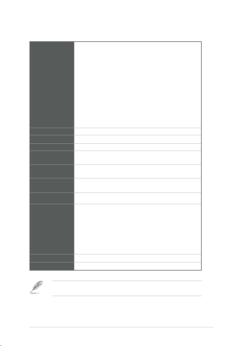
Internal I/O
connectors
GPIO
Watch dog timer
Security
Power
requirement
Operation
Temperature
Non-Operation
Temperature
Operation
Humidity
OS support
Certification
Form Factor
1 x GPIO header (8-bit)
1 x I2C header
1 x LPC Debug header
1 x LPT header
1 x Speaker header
1 x SPI TPM header
1 x System Panel header
2 x USB 2.0 headers support additional 4 USB 2.0 ports
2 x USB 2.0 connectors
1 x WDT Enable jumper
1 x 24-pin ATX power connector
1 x 4-pin ATX power connector
1 x 8-bit GPIO header
Yes
1 x SPI TPM header
AT/ATX mode
0~60°C
-40~85°C
40°C @ 95%
Windows® 7 (32/64-bit)
Windows® 10 (64-bit)
Windows® 10 IoT Enterprise
Ubuntu
RedHat Enterprise
Fedora Workstation
Open SUSE
CE, FCC
ATX Form Factor, 12”x 9.6” (30.5cm x 24.4cm)
NOTE: Specications are subject to change without notice. Please refer to the
ASUS website for the latest specications.
Chapter 1: General information
1-3

1-4
Q170A-IM-A

Chapter 2
Motherboard information
2.1 Before you proceed
Take note of the following precautions before you install motherboard components
or change any motherboard settings.
CAUTION!
• Unplug the power cord from the wall socket before touching any
component.
• Before handling components, use a grounded wrist strap or touch a safely
grounded object or a metal object, such as the power supply case, to avoid
damaging them due to static electricity.
• Hold components by the edges to avoid touching the ICs on them.
• Whenever you uninstall any component, place it on a grounded antistatic
pad or in the bag that came with the component.
• Before you install or remove any component, always remove the AC power
by unplugging the power cord from the power outlet. Failure to do so may
cause severe damage to the motherboard, peripherals, or components.
Chapter 2: Motherboard information
2-1
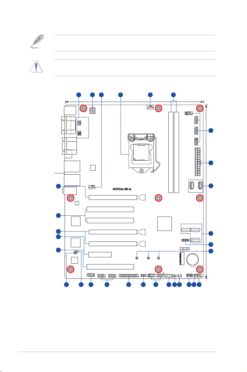
2.2 Motherboard layout
NOTE: Place nine screws into the holes indicated by circles to secure the
motherboard to the chassis.
CAUTION! Do not overtighten the screws! Doing so can damage the
motherboard.
Place this side
towards the rear
of the chassis
24
22
24
23
22
1 432 53
KBMS
COM2
VGA
HDMI
LAN2_U32G1_34
LAN1_U32G1_12
AUDIO
AT_ATX_SEL
ASM
1085
Super
WDT_EN
ALC
887
COM1
I/O
COM2_SEL
COM1_SEL
®
Intel
I219V
ATX12V
I211AT
CHA_FAN
AAFP
®
Intel
PCIEX4
PCIEX16_1
PCI_1
PCI_2
PCIEX16_2
PCIEX16_3
PCI_3
COM3 COM4
6192021 167
24.4cm(9.6in)
LGA1151
2280 2260 2242
LPT
LPC_DEBUG
1718
CPU_FAN
USB78
COM6
DDR4 DIMM_A1* (64bit, 288-pin module)
DDR4 DIMM_B1* (64bit, 288-pin module)
®
Intel
Q170
USB56
GPIO_CON
M.2(SOCKET3)
CLRTC
I2C
SATA6G_1 SATA6G_2
TPM
M.2(SOCKET3)
PCIE SATA IRST
X V X
SPEAKER
CHASSIS
COM5
COM8COM7
EATXPWR
USB9 USB10
SATA6G_3
BATTERY
F_PANEL
1113 1215 14
1
6
2
7
30.5cm(12in)
8
9
10
2-2
Q170A-IM-A
Connectors/Jumpers/Slots Page
1. COM1/2 Ring/+5V/+12V selection jumpers (6-pin COM1_SEL, COM2_SEL) 2-12
2. ATX Power connectors (24-pin EATXPWR, 4-pin ATX12V) 2-16
3. CPU and Chassis Fan headers (4-pin CPU_FAN, 4-pin CHA_FAN) 2-16
4. Intel® LGA1151 CPU socket 2-4
5. DDR4 U-DIMM slots 2-9
6. COM Port headers (10-1 pin COM3 - COM8) 2-17
7.
USB 2.0 headers/connectors (10-1 pin USB56, USB78 / USB9, USB10)
8. Serial ATA 6.0 Gb/s connectors (7-pin SATA6G_1/2/3) 2-18
9. SPI TPM header (14-1 pin TPM) 2-18
10. M.2 slot (SOCKET 3) 2-19
11. System Panel header (10-1 pin F_PANEL) 2-20
12. Speaker header (4-pin SPEAKER) 2-21
13. Chassis Intrusion header (4-1 pin CHASSIS) 2-12
14. Clear RTC RAM (2-pin CLRTC) 2-11
15. I2C header (6-1 pin I2C) 2-21
16. General purpose input/output header (10-pin GPIO_CON) 2-22
17. LPC Debug header (10-1 pin LPC_DEBUG) 2-22
18. LPT header (26-1 pin LPT) 2-23
19. Front Panel Audio header (10-1 pin AAFP) 2-23
20. AT/ATX mode selection jumper (3-pin AT_ATX_SEL) 2-13
21. WDT Enable jumper (2-pin WDT_EN) 2-13
2-17
Chapter 2: Motherboard information
2-3
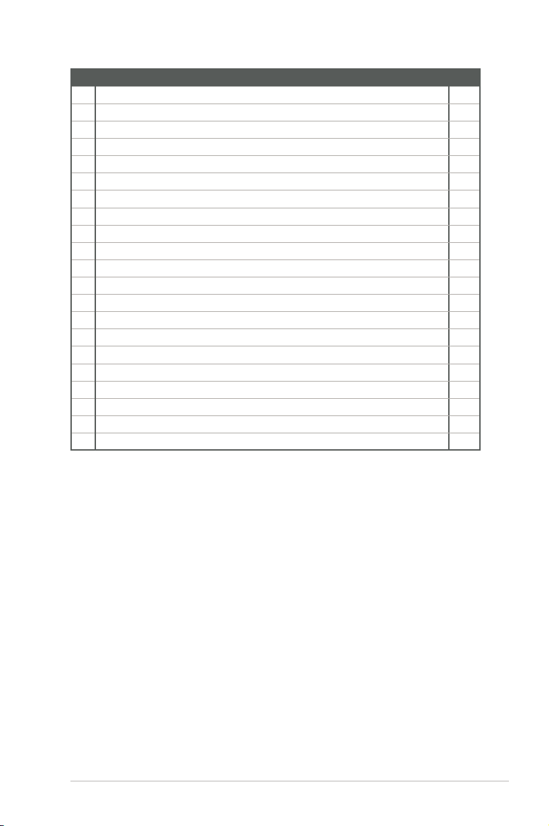
2.3 Central Processing Unit (CPU)
The motherboard comes with a surface mount LGA1151 socket designed for the
th
Intel® 7
Processors.
/ 6th Generation Core™ i7 / Core™ i5 / Core™ i3, Pentium®, and Celeron®
LGA1151
IMPORTANT! Unplug all power cables before installing the CPU.
2-4
CAUTION!
• Upon purchase of the motherboard, ensure that the PnP cap is on
the socket and the socket contacts are not bent. Contact your retailer
immediately if the PnP cap is missing, or if you see any damage to the
PnP cap/socket contacts/motherboard components. The manufacturer will
shoulder the cost of repair only if the damage is shipment/transit-related.
• Keep the cap after installing the motherboard. The manufacturer will
process Return Merchandise Authorization (RMA) requests only if the
motherboard comes with the cap on the LGA1151 socket.
• The product warranty does not cover damage to the socket contacts
resulting from incorrect CPU installation/removal, or misplacement/loss/
incorrect removal of the PnP cap.
Q170A-IM-A
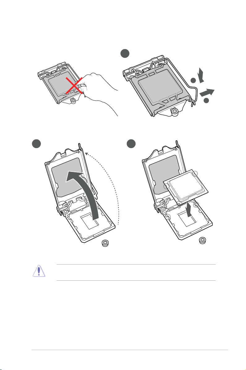
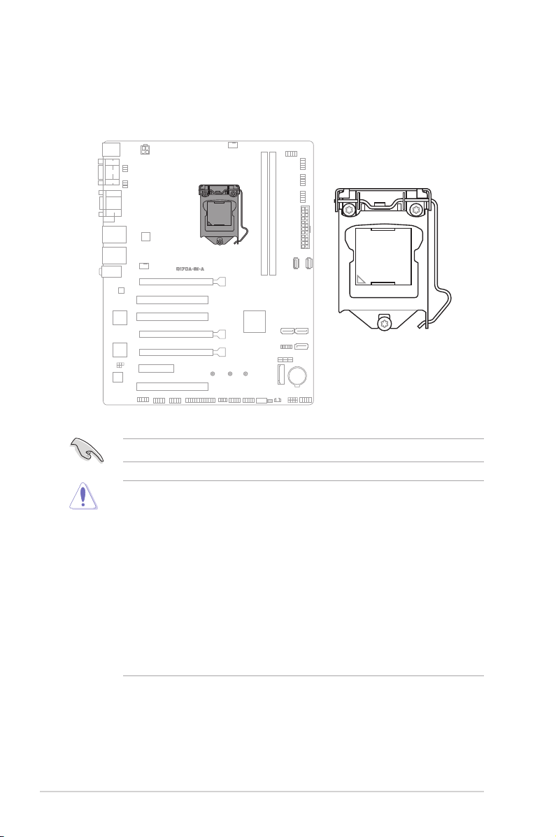
2.3.1 Installing the CPU
2 3
1
A
B
CAUTION! LGA1156 CPU is not compatible with the LGA1151 socket. DO
NOT install an LGA1156 CPU on the LGA1151 socket.
Chapter 2: Motherboard information
2-5
4
A
C
B
5
2-6
Q170A-IM-A
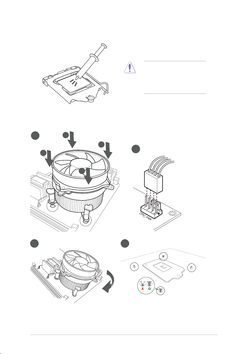
2.3.2 CPU heatsink and fan assembly installation
CAUTION! Apply the Thermal
Interface Material to the CPU
heatsink and CPU before you
install the heatsink and fan if
necessary.
To install the CPU heatsink and fan assembly
1
A
B
B
A
3 4
2
Chapter 2: Motherboard information
2-7
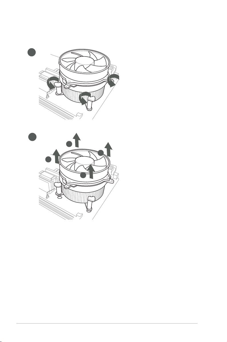
To uninstall the CPU heatsink and fan assembly
1
2
A
B
B
A
2-8
Q170A-IM-A
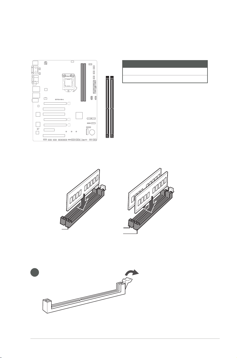
2.4 System memory
This motherboard comes with two Double Data Rate 4 (DDR4) Dual Inline Memory
Module (DIMM) sockets. The gure below illustrates the location of the DDR4
DIMM sockets:
Channel Sockets
Channel A U-DIMM_A1*
DIMM_B1*
DIMM_A1*
Channel B U-DIMM_B1*
Recommended memory configuration
DIMM_B1*
DIMM_A1*
DIMM_B1*
Installing a DIMM
1
Chapter 2: Motherboard information
2-9

2
A
A
B
3
To remove a DIMM
2-10
B
A
Q170A-IM-A

2.5 Jumpers
1. Clear RTC RAM (2-pin CLRTC)
This header allows you to clear the CMOS RTC RAM data of the system
setup information such as date, time, and system passwords.
CLRTC
GND
+3V_BAT
Connector type
HEADER 1x2p, 2.54mm pitch, S/T
To erase the RTC RAM:
1. Turn OFF the computer and unplug the power cord.
2. Use a metal object such as a screwdriver to short the two pins.
3. Plug the power cord and turn ON the computer.
4. Hold down the <Del> key during the boot process and enter BIOS Setup
to re-enter data.
NOTE: If the steps above do not help, remove the onboard battery and move
the jumper again to clear the CMOS RTC RAM data. After clearing the CMOS,
reinstall the battery.
Chapter 2: Motherboard information
2-11

2. COM1/2 Ring/+5V/+12V selection jumpers (6-pin COM1_SEL, COM2_SEL)
A
B
A
COM2_SEL
12 34 56
+5V+12V
(Default)
B
RI
COM1_SEL
12 34 56
RI
+5V+12V
(Default)
Setting Pins
+12V 1-2
+5V 3-4
Ring (Default) 5-6
3. Chassis Intrusion header (4-1 pin_CHASSIS)
This header is for a chassis-mounted intrusion detection sensor or switch.
Connect one end of the chassis intrusion sensor or switch cable to this
connector. The chassis intrusion sensor or switch sends a low-level signal
to this connector when a chassis component is installed. The signal is then
generated as a chassis intrusion event.
2-12
Connector type
CHASSIS
+5VSB_MB
Chassis Signal
GND
PIN 1
HEADER 4p, K2, 2.54mm pitch
Q170A-IM-A

4. AT/ATX mode selection jumper (3-pin AT_ATX_SEL)
AT_ATX_SEL
21 2 3
Pins
1-2 (Default) ATX mode
2-3 AT mode
High Active
(Default)
Low Active
Connector type
HEADER 1x3p, 2.54mm pitch, S/T
5. WDT Enable jumper (2-pin WDT_EN)
A watchdog timer is an electronic timer that is used to detect and recover
from computer malfunctions. The HW WDT (watchdog timer) Enable jumper
allows the HW watchdog resets the system automatically even when the
system crashes.
WDT_EN
21
Connector type
NOTE: By default, this jumper is set to HW WDT enabled with a jumper cap
attached.
HEADER 1x2p, 2.54mm pitch, S/T
Chapter 2: Motherboard information
2-13

2.6 Connectors
2.6.1 Rear panel connectors
1 2 3 5 6
4
987
10
1. PS/2 mouse port (green). This port is for a PS/2 mouse.
2. Serial ports (COM, RS232/RS422/RS485). These ports connect modems, or
other devices that conform with serial specication.
3. Video Graphics Adapter (VGA) port. This 15-pin port is for a VGA monitor
or other VGA-compatible devices.
4. LAN (RJ-45) ports. These ports allow Gigabit connection to a Local Area
Network (LAN) through a network hub.
LAN port LED indications
Activity/Link LED Speed LED
Status Description Status Description
Off No link OFF 10Mbps connection
Orange Linked ORANGE 100Mbps connection
Orange (Blinking) Data activity GREEN 1Gbps connection
Orange (Blinking
then steady)
Ready to wake up
from S5 mode
ACT/LINK
LED
LAN port
SPEED
LED
5. Line In port (light blue). This port connects to the tape, CD, DVD player, or
other audio sources.
6. Line Out port (lime). This port connects to a headphone or a speaker. In the
4.1, and 5.1 channel congurations, the function of this port becomes Front
Speaker Out.
7. PS/2 keyboard port (purple). This port is for a PS/2 keyboard.
8. HDMITM port. This port is for a High-Denition Multimedia Interface (HDMITM)
connector, and is HDCP compliant allowing playback of HD DVD, Blu-ray,
and other protected content.
2-14
Q170A-IM-A

9. USB 3.2 Gen 1 (up to 5Gbps) ports. These 9-pin Universal Serial Bus
(USB) ports are for USB 3.2 Gen 1 devices.
10. Microphone port (pink). This port connects to a microphone.
Refer to the audio conguration table for the function of the audio ports in 2, 4,
5.1, or 7.1-channel conguration.
Audio 2, 4, 5.1 or 7.1-channel configuration
Port
Light Blue (Rear panel) Line In Rear Speaker Out Rear Speaker Out Rear Speaker Out
Lime (Rear panel) Line Out Front Speaker Out Front Speaker Out Front Speaker Out
Pink (Rear panel) Mic In Mic In Bass/Center Bass/Center
Lime (Front panel) - - - Side Speaker Out
To configure a 7.1-channel audio output:
Use a chassis with HD audio module in the front panel to support a
Headset
2-channel
4-channel 5.1-channel 7.1-channel
7.1-channel audio output.
Chapter 2: Motherboard information
2-15

2.6.2 Internal connectors
1. ATX Power connectors (24-pin EATXPWR, 4-pin ATX12V)
Correctly orient the ATX power supply plugs into these connectors and push
down rmly until the connectors completely t.
A
A
ATX12V
+12V_CPU
+12V_CPU
GND
PIN 1
GND
B
EATXPWR
+3.3V
+12V
+12V
+5VSB
NC
GND
+5V
GND
+5V
GND
+3.3V
+3.3V
B
GND
+5V
+5V
+5V
-5V
GND
GND
GND
ATX_PSON#_R
GND
-12V
+3.3V
PIN 1
2. CPU and Chassis Fan headers (4-pin CPU_FAN, 4-pin CHA_FAN)
Connect the fan cables to the fan headers on the motherboard, ensuring that
the black wire of each cable matches the ground pin of the header.
A
A
B
CPU_FAN
B
CHA_FAN
12V
FAN_IN
FAN_PWM
GND
2-16
Connector type
WAFER HD 4p, 2.54mm pitch, S/T
CAUTION! Do not forget to connect the fan cables to the fan headers.
Insufcient air flow inside the system may damage the motherboard
components. These are not jumpers! Do not place jumper caps on the fan
headers!
Q170A-IM-A

3. COM Port headers (10-1 pin COM3 - COM8)
A
These headers are for serial (COM) ports. Connect the serial port cables to
these headers, then install the module to a slot opening at the back of the
system chassis.
A B
COM6 COM5
B
C D
COM8 COM7
C
D
E F
E F
RI1#
CTS1#
RTS1#
DSR1#
GND
DTR1#
TXD1
RXD1
DCD1#
PIN 1
COM3 COM4
RXD1
DTR1#
DSR1#
CTS1#
PIN 1
RI1#
GND
TXD1
RTS1#
DCD1#
Connector type
Header 2x5p, K10, 2.54mm pitch
NOTE: The serial port cables are purchased separately.
4. USB 2.0 headers/connectors (10-1 pin USB56, USB78 / USB9, USB10)
These connectors are for USB 2.0 ports. Connect the USB cables to the
connectors. The USB connector complies with USB 2.0 specication that
supports up to 480 Mbps connection speed.
A B
USB9 USB10
A B
C
USB78
PIN 1
C D
Connector type
Header 2x5p, K9, 2.54mm pitch
CAUTION! Never connect a 1394 cable to the USB connector. Doing so will
damage the motherboard.
USB+5V
USB_P7-
USB+5V
USB_P8-
USB_P7+
GND
NC
GND
USB_P8+
D
PIN 1
USB56
USB+5V
USB_P5-
USB+5V
USB_P6-
USB_P5+
GND
NC
GND
USB_P6+
NOTE: The USB cable is purchased separately.
Chapter 2: Motherboard information
2-17

5. Serial ATA 6.0Gb/s ports (7-pin SATA6G_1/2/3)
These ports connect to SATA 6.0 Gb/s hard disk drives or optical drives via
SATA 6.0 Gb/s signal cables.
GND
RSATA_TXP
RSATA_TXN
GND
RSATA_RXN
RSATA_RXP
GND
RSATA_RXP
RSATA_RXN
GND
RSATA_TXN
GND
GND
RSATA_TXP
A B
A
SATA6G_1
SATA6G_2
B
C
C
SATA6G_3
6. SPI TPM header (14-1 pin TPM)
This header supports a Trusted Platform Module (TPM) system with a
Serial Peripheral Interface (SPI), allowing you to securely store keys, digital
certicates, passwords and data. A TPM system also enhances network
security, protects digital identities, and ensures platform integrity.
2-18
Connector type
SPI TPM IRQ#
SPI TPM CS#
SPI FLASH WP#
GND
TPM
PIN 1
PLTRST#
+1.8V TPM
Header 2x7p, K14, 2.0mm pitch
SPI CLK
SPI MOSI
SPI CS#
+18V SPI
SPI MISO
SPI HOLD#
Q170A-IM-A

7. M.2 slot (SOCKET 3)
This slot allows you to install an M.2 SSD module.
M.2(SOCKET3)
NOTES:
• The M.2 SSD module is purchased separately.
• This slot supports M Key and 2242/2260/2280 storage devices.
Chapter 2: Motherboard information
2-19

8. Front Panel System Panel header (10-1 pin F_PANEL)
This header supports several chassis-mounted functions.
PWR_BTN
+PWR_LED
PLED+
PLED-
PWRBTN#_PANEL
GND
Connector type
F_PANEL
Header 2x5p, K10, 2.54mm pitch
PIN 1
GND
HDD_LED-
HDD_LED+
O_RSTCON#_PR
+HDD_LED RESET
NC
• System power LED (2-pin +PWR_LED)
This 2-pin header is for the system power LED. Connect the chassis
power LED cable to this header. The system power LED lights up when
you turn on the system power, and blinks when the system is in sleep
mode.
•
Hard disk drive activity LED (2-pin +HDD_LED)
This 2-pin header is for the HDD Activity LED. Connect the HDD Activity
LED cable to this header. The IDE LED lights up or flashes when data
is read from or written to the HDD.
•
ATX power button/soft-off button (2-pin PWR_BTN)
This 2-pin header is for the system power button.
•
Reset button (2-pin RESET)
This 2-pin header is for the chassis-mounted reset button for system
reboot without turning off the system power.
2-20
Q170A-IM-A

9. Speaker header (4-pin SPEAKER)
The 4-pin header is for the chassis-mounted system warning speaker. The
speaker allows you to hear system beeps and warnings.
SPEAKER
+5V
GND
GND
SPKO
PIN 1
Connector type
HEADER 1x4p, 2.54mm pitch, S/T
10. I2C header (6-1 pin 12C)
The I2C (Inter-Integrated Circuit) header allows you to connect an I
compatible IoT security module.
I2C
PWR 3.3V
NC
PIN 1
GND
I2C_CLK
I2C_DATA
Connector type
Header 2x3p, K6, 2.0mm pitch
2
C
Chapter 2: Motherboard information
2-21

11. General purpose input/output header (10-pin GPIO_CON)
This header is for a general purpose input/output module which allows you to
customize the digital signal input/output.
GPIO_CON
GND
GPIO8
GPIO6
GPIO4
GPIO2
PIN 1
GPIO7
GPIO5
GPIO3
GPIO1
+5VSB
Connector type
WAFER HD 2x5p, 2.0mm pitch, S/T
12. LPC Debug header
This header allows connection to a LPC Debug card.
LPC_DEBUG
Connector type
IMPORTANT!
• Scan the QR code to view the meaning of each debugging code.
• Debugging codes are only available for ASUS LPC Debug cards.
• Contact your region sales representative for LPC Debug cards ordering.
HEADER 2x5p, K10, 2.0mm pitch
PIN 1
+3V
+3V
SLAD0_SIO
SLAD1_SIO
CK_24M_DEBUG_LPC
GND
SLAD2_SIO
SLAD3_SIO
S_LFRAME#
2-22
Q170A-IM-A

13. LPT header (26-1 pin LPT)
The LPT (Line Printing Terminal) header supports devices such as a printer.
LPT is standardized as IEEE 1284, which is the parallel port interface on IBM
PC-compatible computers.
LPT_XAFD#
LPT_ERROR#
LPT_XINIT#
LPT_XSLIN#
GND
GND
GND
GND
GND
GND
GND
GND
LPT
PIN 1
LPT_PE
LPT_XPD0
LPT_XPD1
LPT_XPD2
LPT_XSTB#
LPT_XPD3
LPT_XPD4
LPT_XPD5
LPT_XPD6
LPT_XPD7
LPT_ACK#
LPT_SLCT
LPT_BUSY
14. Front Panel Audio header (10-1 pin AAFP)
This header is for a chassis-mounted front panel audio I/O module that
supports HD Audio standard. Connect one end of the front panel audio I/O
module cable to this header.
Connector type
HEADER 2x5p, K8, 2.54mm pitch
IMPORTANT!
• We recommend that you connect a high-denition front panel audio module
to this header to avail of the motherboard’s high-denition audio capability.
• If you want to connect a high-denition front panel audio module to this
header, set the HD Audio Controller item in the BIOS Setup to [Enabled].
Chapter 2: Motherboard information
AAFP
A_GNDNCA_JD_FMIC1
PIN 1
A_FMIC1_L
A_FMIC1_R
A_JD_HPOUT
A_HPOUT_L
A_HPOUT_R
A_JD_FRONT
2-23

2-24
Q170A-IM-A

Chapter 3
BIOS setup
Scan the QR code to view the BIOS update guide.
3.1 BIOS Setup program
Use the BIOS Setup program to update the BIOS or congure its parameters. The
BIOS screens include navigation keys and brief online help to guide you in using
the BIOS Setup program.
To enter BIOS Setup at startup:
Press <Delete> or <F2> during the Power-On Self Test (POST). If you do not
press <Delete> or <F2>, POST continues with its routines.
To enter BIOS Setup after POST:
• Press <Ctrl>+<Alt>+<Del> simultaneously.
• Press the reset button on the system chassis.
• Press the power button to turn the system off then back on. Do this option only
if you failed to enter BIOS Setup using the rst two options.
NOTE: Using the power button, reset button, or the <Ctrl>+<Alt>+<Del> keys
to reboot a running operating system can cause damage to your data or system.
Always shut down the system properly from the operating system.
IMPORTANT!
• Visit the ASUS website at www.asus.com to download the latest BIOS le
for this motherboard.
• The default BIOS settings for this motherboard apply to most working
conditions and ensures optimal performance. If the system becomes
unstable after changing any BIOS settings, load the default settings to
regain system stability. Select the option Restore Defaults under the Exit
Menu or press hotkey <F3>.
• The BIOS Setup screens shown in this section are for reference purposes
only, and may not exactly match what you see on your screen.
Chapter 3: BIOS setup
3-1

3.1.1 BIOS menu screen
Menu bar
The menu bar on top of the screen has the following main items:
Main
Advanced
Hardware
Monitor
Security
Boot
Exit
To select an item on the menu bar, press the right or left arrow key on the
keyboard until the desired item is highlighted.
For changing the basic system conguration.
For changing the advanced system settings.
For displaying the system temperature and changing the
fan settings.
For conguring the system security settings.
For changing the system boot conguration.
For selecting the save options and default options.
3.2 Main menu
The Main menu provides you an overview of the basic system information, and
allows you to set the system date, time, language, and security settings.
3.2.1 System Date [Day MM/DD/YYYY]
Allows you to set the system date.
3.2.2 System Time [HH:MM:SS]
Allows you to set the system time.
3.3 Advanced menu
The Advanced menu items allow you to change the settings for the CPU and other
system devices.
Be cautious when changing the settings of the Advanced menu items. Incorrect
eld values can cause the system to malfunction.
3.3.1 PCH-FW Configuration
TPM Device Selection
Allows you to select the TPM device. Conguration options: [dTPM] [PTT]
3.3.2 Trusted Computing
Security Device Support
Allows you to enable or disable BIOS support for security devices.
Conguration options: [Disabled] [Enabled]
3-2
Q170A-IM-A

3.3.3 CPU Configuration
The items in this menu show CPU-related information the BIOS automatically
detects.
The items shown in the submenu may be different depending on the type of
CPU installed.
Intel (VMX) Virtualization Technology
When set to [Enabled], a VMM can utilize the additional hardware capabilities
provided by Vanderpool Technology. Conguration options: [Disabled] [Enabled]
Intel Trusted Execution Technology
When set to [Enabled], allows you to enable the utilization of additional hardware
capabilities provided by Intel® Trusted Execution Technology and requires a full
power cycyle. Conguration options: [Disabled] [Enabled]
Hyper-Threading
The Intel Hyper-Threading Technology allows a hyper-threading processor to
appear as two logical processors to the operating system, allowing the operating
system to schedule two threads or processes simultaneously.
[Enabled] Two threads per activated core are enabled.
[Disabled] Only one thread per activated core is enabled.
VT-d [Disabled]
Allows you to enable or disable VT-d function on MCH.
Conguration options: [Enabled] [Disabled]
CPU Power Management Control
Allows you to manage and congure the CPU’s power.
Intel(R) SpeedStep(tm)
Allows your system to support more than two frequency ranges.
Conguration options: [Disabled] [Enabled]
Intel(R) Speed Shift Technology
Allows you to enable or disable Intel(R) Speed Shift Technology support.
When enabled, CPPC v2 interface allows hardware controlled P-state.
Conguration options: [Disabled] [Enabled]
Turbo Mode
Allows you to enable or disable Turbo Mode for your processor.
Conguration options: [Enabled] [Disabled]
CPU C states
Allows to enable or disable the CPU C states.
Conguration options: [Disabled] [Enabled]
Chapter 3: BIOS setup
3-3

Enhanced C-states
Allows to enable or disable the enhanced C1 state.
Conguration options: [Disabled] [Enabled]
Package C State limit
Allows you to disable or enable the whole C-State package support.
Conguration options: [C0/C1] [C2] [C3] [C6] [C7] [C7s] [C8] [Cpu Default]
[Auto]
3.3.4 Graphics Configuration
The items in this menu allow you to select a primary display from IGFX, PEG and
PCI graphical devices.
Primary Display
Allows you to select which of the IGFX/PEG/PCI Graphics device should be the
Primary Display. Conguration options: [Auto] [IGFX] [PEG] [PCI]
Internal Graphics
[Auto] Keep IGFX enabled base on the setup options.
[Disabled] Disables internal graphics.
[Enabled] Enables internal graphics.
RC6 (Render Standby)
Allows you to enable or disable render standby support.
Conguration options: [Disabled] [Enabled]
3.3.5 PCI Express Configuration
Allows you to select a PEG or PCI graphical device.
PCIEX16_1 Slot
Enable Root Port
Allows you to enable or disable the root port.
Conguration options: [Disabled] [Enabled] [Auto]
Max Link Speed
Allows you to congure PEG 0:1:0.
Conguration options: [Auto] [Gen1] [Gen2] [Gen 3]
Max Link Width
Allows you to force the PEG link to x1, x2, x4 or x8.
Conguration options: [Auto] [Force X1] [Force X2] [Force X4] [Force X8]
ASPM
Allows you to control the ASPM (Active State Power Management) for PEG
0. It does not work if PEG is not the current active device. Conguration
options: [Disabled] [Auto] [ASPM L0s] [ASPM L1] [ASPM L0sL1]
3-4
Q170A-IM-A

Detect Non-Compliance Device
Allows you to enable or disable the detection function of non-compliance PCI
Express device. Conguration options: [Disabled] [Enabled]
PCIEX16_2 Slot
PCIEX16_2 Slot
Allows you to enable or disable the PCIEX16_2 slot.
Conguration options: [Disabled] [Enabled]
ASPM
Allows you to control the Active State Power Management on both NB
(NorthBridge) side and SB (SouthBridge) side of the DMI Link.
Conguration options: [Disabled] [L0s] [L1] [L0sL1] [Auto]
L1 Substates
Allows you to select the PCI Express L1 Substates settings.
Conguration options: [Disabled] [L1.1] [L1.1 & L1.2]
PCIe Speed
Congures the speed of the PCIEX16_2 slot.
Conguration options: [Auto] [Gen1] [Gen2]
Detect Timeout
Allows you to set the time (in milliseconds) of waiting for link to exit Detect
state for enabled ports before assuming there is no device and potentially
disabling the port. Use the <+> and <-> keys to adjust the value or input the
desired value directly.
Hot Plug
Allow you to enable and disable the PCIEX16_2 slot Hot Plug support.
Conguration options: [Disabled] [Enabled]
Detect Non-Compliance Device
Allows you to enable or disable the detection function of non-compliance PCI
Express device. Conguration options: [Disabled] [Enabled]
PCIEX16_3 Slot
PCIEX16_3 Slot
Allows you to enable or disable the PCIEX16_3 slot.
Conguration options: [Disabled] [Enabled]
ASPM
Allows you to control the Active State Power Management on both NB
(NorthBridge) side and SB (SouthBridge) side of the DMI Link.
Conguration options: [Disabled] [L0s] [L1] [L0sL1] [Auto]
Chapter 3: BIOS setup
3-5

L1 Substates
Allows you to select the PCI Express L1 Substates settings.
Conguration options: [Disabled] [L1.1] [L1.1 & L1.2]
PCIe Speed
Congures the speed of the PCIEX16_3 slot.
Conguration options: [Auto] [Gen1] [Gen2]
Detect Timeout
Allows you to set the time (in milliseconds) of waiting for link to exit Detect
state for enabled ports before assuming there is no device and potentially
disabling the port. Use the <+> and <-> keys to adjust the value or input the
desired value directly.
Hot Plug
Allow you to enable and disable the PCIEX16_3 slot Hot Plug support.
Conguration options: [Disabled] [Enabled]
Detect Non-Compliance Device
Allows you to enable or disable the detection function of non-compliance PCI
Express device. Conguration options: [Disabled] [Enabled]
PCIEX4 Slot
PCIEX4 Slot
Allows you to enable or disable the PCIEX4 slot.
Conguration options: [Disabled] [Enabled]
ASPM
Allows you to control the Active State Power Management on both NB
(NorthBridge) side and SB (SouthBridge) side of the DMI Link.
Conguration options: [Disabled] [L0s] [L1] [L0sL1] [Auto]
L1 Substates
Allows you to select the PCI Express L1 Substates settings.
Conguration options: [Disabled] [L1.1] [L1.1 & L1.2]
PCIe Speed
Congures the speed of the PCIEX4 slot.
Conguration options: [Auto] [Gen1] [Gen2]
Detect Timeout
Allows you to set the time (in milliseconds) of waiting for link to exit Detect
state for enabled ports before assuming there is no device and potentially
disabling the port. Use the <+> and <-> keys to adjust the value or input the
desired value directly.
3-6
Q170A-IM-A

Hot Plug
Allow you to enable and disable the PCIEX4 slot Hot Plug support.
Conguration options: [Disabled] [Enabled]
Detect Non-Compliance Device
Allows you to enable or disable the detection function of non-compliance PCI
Express device. Conguration options: [Disabled] [Enabled]
3.3.6 CSM Configuration
CSM Support
Allow you to enable/disable the CSM support.
Conguration options: [Disabled] [Enabled]
Network
Controls the execution of UEFI and Legacy PXE OpROM.
Conguration options: [Do not launch] [UEFI] [Legacy]
Storage
Controls the execution of UEFI and Legacy Storage OpROM.
Conguration options: [Do not launch] [UEFI] [Legacy]
Video
Controls the execution of UEFI and Legacy Video OpROM.
Conguration options: [Do not launch] [UEFI] [Legacy]
Other PCI devices
Determines OpROM execution policy for devices other than Network, Storage, or
Video. Conguration options: [Do not launch] [UEFI] [Legacy]
3.3.7 Super IO Configuration
NCT6116D Super IO Configuration
Serial Port 1 Configuration
Serial Port
Allows you to enable or disable the serial port (COM).
Conguration options: [Disabled] [Enabled]
The following items appear only when you set Serial Port to [Enabled].
COM1 Control
Allows you to select the COM1 mode.
Conguration options: [RS232] [RS422] [RS485]
Chapter 3: BIOS setup
3-7

Serial Port 2 Configuration
Serial Port
Allows you to enable or disable the serial port (COM).
Conguration options: [Disabled] [Enabled]
The following item appears only when you set Serial Port to [Enabled].
COM2 Control
Allows you to select the COM2 mode.
Conguration options: [RS232] [RS422] [RS485]
Serial Port 3 Configuration
Serial Port
Allows you to enable or disable the serial port (COM).
Conguration options: [Disabled] [Enabled]
Serial Port 4 Configuration
Serial Port
Allows you to enable or disable the serial port (COM).
Conguration options: [Disabled] [Enabled]
Parallel Port Configuration
Parallel Port
Allows you to enable or disable the Parallel port (LPT/LPTE).
Conguration options: [Disabled] [Enabled]
3-8
The following items appear only when you set Parallel Port to [Enabled].
Change Settings [Auto]
This item allows you to select an optimal setting for Super I/O Device.
Conguration options: [Auto] [IO=378h; IRQ=5]
[IO=378h; IRQ=5, 6, 7, 9, 10, 11, 12;]
[IO=278h; IRQ=5, 6, 7, 9, 10, 11, 12;]
[IO=3BCh; IRQ=5, 6, 7, 9, 10, 11, 12;]
Mode [RS232]
Allows you to select the Parallel Port mode.
Conguration options: [STD Printer Mode] [SPP Mode]
[EPP-1.9 and SPP Mode] [EPP-1.7 and SPP Mode]
[ECP Mode] [ECP and EPP 1.9 Mode]
[ECP and EPP 1.7 Mode]
Q170A-IM-A

NCT5104DSEC Super IO Configuration
Serial Port 5/6/7/8 Configuration
Serial Port
Allows you to enable or disable the serial port (COM).
Conguration options: [Disabled] [Enabled]
3.3.8 Serial Console Configuration
COM1~COM8
Console Redirection
Allows you enable or disable the console redirection feature.
Conguration options: [Enabled] [Disabled]
3.3.9 SATA Configuration
SATA6G_1/2/3
Allow you to enable/disable the SATA6G_1/2/3 port.
Conguration options: [Disabled] [Enabled]
Hot Plug
These items allow you to enable/disable SATA Hot Plug support.
Conguration options: [Disabled] [Enabled]
M.2
Allow you to enable/disable the M.2 (SOCKET3).
Conguration options: [Disabled] [Enabled]
3.3.10 USB Configuration
LAN1_U32G1_1/2, LAN2_U32G1_3/4
Allows you to enable or disable USB port. Once set to [Disabled], any USB
devices plugged into the connector will not be detected by BIOS or OS.
Conguration options: [Disabled] [Enabled]
USB5-10
Allows you to enable or disable USB port. Once set to [Disabled], any USB
devices plugged into the connector will not be detected by BIOS or OS.
Conguration options: [Disabled] [Enabled]
3.3.11 Onboard Devices Configuration
I2C1 Controller
This item allows you to enable or disable the Serial IO Controller.
Conguration options: [Enabled] [Disabled]
Chapter 3: BIOS setup
3-9

Audio Controller
[Enabled] Enables the HD Audio Device.
[Disabled] Disables the HD Audio Device.
Intel LAN1 Controller
[Enabled] Enables the Intel LAN1 controller.
[Disabled] Disables the controller.
Intel LAN PXE OPROM
This item allows you to enable or disable the PXE Option ROM of the Intel LAN1
controller. Conguration options: [Disabled] [Enabled]
Intel LAN2 Controller
[Enabled] Enables the Intel LAN2 controller.
[Disabled] Disables the controller.
Intel LAN2 PXE OPROM
This item allows you to enable or disable the PXE Option ROM of the Intel LAN2
controller. Conguration options: [Disabled] [Enabled]
3.3.12 APM Configuration
ErP Ready
Allows you to switch off some power at S5 to get the system ready for ErP
requirement. When set to [Enabled], all other PME options will be switched off.
Conguration options: [Disabled] [Enabled]
Restore AC Power Loss
[S5 State] The system goes into off state after an AC power loss.
[S0 State] The system goes into on state after an AC power loss.
Power On By PCI-E
This item allows you to enable or disable the Wake-on-LAN function of the onboard
LAN controller or other installed PCIe LAN cards.
Conguration options: [Disabled] [Enabled]
Power On By PCI
This item allows you to enable or disable the Wake-on-LAN function of the onboard
LAN controller or other installed PCI LAN cards.
Conguration options: [Disabled] [Enabled]
Power On By Ring
[Enabled] Enables the Ring devices to generate a wake event.
[Disabled] Disables the Ring devices to generate a wake event.
3-10
Q170A-IM-A

Power On By RTC
[Enabled] When set to [Enabled], the items RTC Alarm Date(Days) and
Hour/Minute/Second are use-confgurable with set values.
[Disabled] Disables RTC to generate a wake event.
3.3.13 EzFlash
Enter Ez-Flash mode
This item allows you to run EzFlash utility. When you press <Enter>, a conrmation
message appears. Use the left/right arrow key to select between [Yes] or [No],
then press <Enter> to conrm your choice.
3.3.14 Watchdog Timer
Watchdog Support
This item allows you to enable or disable Watchdog timer.
Conguration options: [Enabled] [Disabled]
Watchdog Timer
Use the <+> and <-> keys to adjust the value or input the desired value directly.
The value ranges from 1 to 255.
3.3.15 Network Stack Configuration
Network Stack
This item allows user to disable or enable the UEFI network stack.
Conguration options: [Disabled] [Enabled]
The following items appear only when you set Network Stack to [Enabled].
Ipv4 PXE Support
This item allows user to disable or enable the Ipv4 PXE Boot support.
Conguration options: [Disabled] [Enabled]
Ipv6 PXE Support
This item allows user to disable or enable the Ipv6 PXE Boot support.
Conguration options: [Disabled] [Enabled]
3.3.16 Miscellaneous
DMI/OPI Configuration
DMI Link ASPM Control
This item allows you to control the Active State Power Management on SA side of
the DMI Link. Conguration options: [Disabled][L1]
Chapter 3: BIOS setup
3-11

PCI Express Configuration
DMI Link ASPM Control
This item allows you to control the Active State Power Management of the DMI
Link. Conguration options: [Disabled] [Enabled]
3.4 Hardware Monitor menu
The items in this menu provide you an overview of system status including
temperature, fan speed and voltage, and allow you to congure the smart fan.
Smart Fan Mode
Allows you to select the smart fan mode. Conguration options: [Disabled] [Normal]
[Manual Mode]
The following item appears only when you set Smart Fan Mode to [Manual
Mode].
Smart Fan Function
Chassis Fan Setting
Temperature 1/2/3/4
Input value range: [0~255]
FD/RPM 1/2/3/4
Input value range: [0~255]
Cpu Fan Setting
Temperature 1/2/3/4
Input value range: [0~255]
FD/RPM 1/2/3/4
Input value range: [0~255]
3.5 Security menu
This menu allows a new password to be created or a current password to be changed. The
menu also enables or disables the Secure Boot state and lets the user congure the System
Mode state.
Administrator Password
If you have set an administrator password, we recommend that you enter the
administrator password for accessing the system.
To set an administrator password:
1. Select the Administrator Password item and press <Enter>.
2. From the Create New Password box, key in a password, then press <Enter>.
3. Conrm the password when prompted.
3-12
Q170A-IM-A

To change an administrator password:
1. Select the Administrator Password item and press <Enter>.
2. From the Enter Current Password box, key in the current password, then press
<Enter>.
3. From the Create New Password box, key in a new password, then press <Enter>.
4. Conrm the password when prompted.
To clear the administrator password, follow the same steps as in changing an
administrator password, but press <Enter> when prompted to create/conrm the
password.
User Password
If you have set a user password, you must enter the user password for accessing
the system. The User Password item on top of the screen shows the default Not
Installed. After you set a password, this item shows Installed.
To set a user password:
1. Select the User Password item and press <Enter>.
2. From the Create New Password box, key in a password, then press <Enter>.
3. Conrm the password when prompted.
To change a user password:
1. Select the User Password item and press <Enter>.
2. From the Enter Current Password box, key in the current password, then press
<Enter>.
3. From the Create New Password box, key in a new password, then press <Enter>.
4. Conrm the password when prompted.
To clear a user password:
1. Select the Clear User Password item and press <Enter>.
2. Select Yes from the Warning message window then press <Enter>.
Secure Boot
Secure Boot
Secure Boot can be enabled if the system is running in User mode with
enrolled platform Key (EPK) or if the CSM function is disabled. Conguration
options: [Disabled] [Enabled]
Secure Boot Mode
In Custom mode, Secure Boot policy variables can be congured by a
physically present user without full authentication. Conguration options:
[Standard] [Custom]
Key Management
The Key Management item allows you to modify Secure Boot variables and
set Key Management page.
Platform Key (PK) / Key Exchange Keys / Authorized Signatures / Forbidden Signatures
Conguration options: [Details] [Export] [Update] [Delete]
Chapter 3: BIOS setup
3-13

3.6 Boot menu
The Boot menu items allow you to change the system boot options.
Boot Configuration
CHASSIS INTRUDE
Allows you to enable or disable the chassis intrusion detection function.
Conguration options: [Disabled] [Enabled]
Setup Prompt Timeout
Allows you to set the number of seconds to wait for setup activation key.
65535(0xFFFF) means indenite waiting. Conguration options: [1] - [65535]
Boot up NumLock State
[On] Set the power-on state of the NumLock to [On].
[Off] Set the power-on state of the NumLock to [Off].
Quiet Boot
Allows you to enable or disable the Quiet Boot option.
Conguration options: [Disabled] [Enabled]
Fast Boot [Enabled]
[Enabled] Select to accelerate the boot speed.
[Disabled] Select to go back to normal boot.
The following four items appear when you set Fast Boot to [Enabled].
3-14
SATA Support
[All Devices] All devices connected to SATA ports will be available
during POST. This process will extend the POST time.
[Last Boot
SATA Devices
Only]
NVMe Support
[Disabled] NVMe device will be skipped in fast boot mode.
[Enabled] NVMe device will be enabled in fast boot mode.
VGA Support
[Auto] Only installing Legacy OpROM with Legacy OS and logo
[EFI Driver] Only EFI driver will be installed with EFI OS.
Only the last boot SATA devices connected to SATA ports
will be detected during POST. Any hardware change will
disable fast boot.
will not display during POST .
Q170A-IM-A

USB Support
[Disabled] All USB devices will not be available until OS boot up for
a fastest POST time.
[Full Initial] All USB devices will be available during POST. This
process will extend the POST time.
[Partial Initial] For a faster POST time, only the USB ports with keyboard
and mouse connections will be detected.
PS/2 Devices Support
Select any of these settings when PS/2 devices are installed. These settings
only apply when Fast Boot is enabled.
[Enabled] PS/2 devices will be available during POST at any
circumstances. This process will extend POST time.
[Disabled] For the fastest POST time, all PS/2 devices will not be
available until your computer enters the operating system.
Network Stack Driver Support
[Disabled] Select to skip the network stack driver from loading during
POST.
[Enabled] Select to load the network stack driver during POST.
Redirection Support
[Disabled] Select to skip the redirection function during POST.
[Enabled] Select to enable the redirection function driver during
POST.
Boot mode select
Allows you to select the boot mode. Conguration options: [LEGACY] [UEFI]
FIXED BOOT ORDER Priorities
Boot Option #1~#6
This item allows you to set the system boot order. Conguration options: [Hard
Disk] [NVME] [CD/DVD] [SD] [USB Device] [Network] [Disabled]
Chapter 3: BIOS setup
3-15

3.7 Exit menu
The Exit menu items allow you to save or discard your changes to the BIOS items.
Save Changes & Exit
This option allows you to save your changes and exit the Setup program. When
you select this option or if you press <Esc>, a conrmation window appears. Select
Yes to save changes and exit.
Discard Changes & Exit
This option allows you to exit the Setup program without saving your changes.
When you select this option or if you press <Esc>, a conrmation window appears.
Select Yes to discard changes and exit.
Save Changes & Reset
This option allows you to exit the Setup program after saving changes.
Discard Changes & Reset
This option allows you to exit the Setup program without saving changes.
Save changes
This option allows you to save changes to any of the setup options you have made
so far.
Discard changes
This option allows you to discard changes to any of the setup options you have
made so far.
Restore Defaults
Restore/load default values for all the setup options.
Save as User Defaults
This option allows you to save the changes you have made so far as user defaults.
Restore User Defaults
Restore the user defaults with all the setup options.
3-16
Q170A-IM-A

Appendix
Notices
FCC Compliance Information
Responsible Party: Asus Computer International
Address: 48720 Kato Rd., Fremont, CA 94538, USA
Phone / Fax No: (510)739-3777 / (510)608-4555
This device complies with part 15 of the FCC Rules. Operation is subject to the following
two conditions: (1) This device may not cause harmful interference, and (2) this device must
accept any interference received, including interference that may cause undesired operation.
This equipment has been tested and found to comply with the limits for a Class B digital
device, pursuant to part 15 of the FCC Rules. These limits are designed to provide
reasonable protection against harmful interference in a residential installation. This equipment
generates, uses and can radiate radio frequency energy and, if not installed and used in
accordance with the instructions, may cause harmful interference to radio communications.
However, there is no guarantee that interference will not occur in a particular installation. If
this equipment does cause harmful interference to radio or television reception, which can be
determined by turning the equipment off and on, the user is encouraged to try to correct the
interference by one or more of the following measures:
- Reorient or relocate the receiving antenna.
- Increase the separation between the equipment and receiver.
- Connect the equipment into an outlet on a circuit different from that to which the receiver is
connected.
- Consult the dealer or an experienced radio/TV technician for help.
Appendix
A-1

Compliance Statement of Innovation, Science and Economic
Development Canada (ISED)
This device complies with Innovation, Science and Economic Development Canada licence
exempt RSS standard(s). Operation is subject to the following two conditions: (1) this device
may not cause interference, and (2) this device must accept any interference, including
interference that may cause undesired operation of the device.
CAN ICES-003(B)/NMB-003(B)
Déclaration de conformité de Innovation, Sciences et
Développement économique Canada (ISED)
Le présent appareil est conforme aux CNR d’Innovation, Sciences et Développement
économique Canada applicables aux appareils radio exempts de licence. L’exploitation est
autorisée aux deux conditions suivantes : (1) l’appareil ne doit pas produire de brouillage,
et (2) l’utilisateur de l’appareil doit accepter tout brouillage radioélectrique subi, même si le
brouillage est susceptible d’en compromettre le fonctionnement.
CAN ICES-003(B)/NMB-003(B)
VCCI: Japan Compliance Statement
Class B ITE
KC: Korea Warning Statement
HDMI Compliance Statement
The terms HDMI, HDMI High-Denition Multimedia Interface, and the HDMI Logo are
trademarks or registered trademarks of HDMI Licensing Administrator, Inc.
A-2
Q170A-IM-A

REACH
Complying with the REACH (Registration, Evaluation, Authorisation, and Restriction of
Chemicals) regulatory framework, we published the chemical substances in our products at
ASUS REACH website at http://csr.asus.com/english/REACH.htm.
DO NOT throw the motherboard in municipal waste. This product has been designed to
enable proper reuse of parts and recycling. This symbol of the crossed out wheeled bin
indicates that the product (electrical and electronic equipment) should not be placed in
municipal waste. Check local regulations for disposal of electronic products.
DO NOT throw the mercury-containing button cell battery in municipal waste. This symbol
of the crossed out wheeled bin indicates that the battery should not be placed in municipal
waste.
ASUS Recycling/Takeback Services
ASUS recycling and takeback programs come from our commitment to the highest standards
for protecting our environment. We believe in providing solutions for you to be able to
responsibly recycle our products, batteries, other components as well as the packaging
materials. Please go to http://csr.asus.com/english/Takeback.htm for detailed recycling
information in different regions.
Regional notice for California
WARNING
Cancer and Reproductive Harm www.P65Warnings.ca.gov
Google™ License Terms
Copyright© 2021 Google Inc. All Rights Reserved.
Licensed under the Apache License, Version 2.0 (the “License”); you may not use this le
except in compliance with the License. You may obtain a copy of the License at:
http://www.apache.org/licenses/LICENSE-2.0
Unless required by applicable law or agreed to in writing, software distributed under the
License is distributed on an “AS IS” BASIS, WITHOUT WARRANTIES OR CONDITIONS OF
ANY KIND, either express or implied.
See the License for the specic language governing permissions and limitations under the
License.
Appendix
A-3

English ASUSTeK Computer Inc. hereby declares that this device is in
compliance with the essential requirements and other relevant provisions of
related Directives. Full text of EU declaration of conformity is available at:
www.asus.com/support
Français AsusTek Computer Inc. déclare par la présente que cet appareil est
conforme aux critères essentiels et autres clauses pertinentes des directives
concernées. La déclaration de conformité de l’UE peut être téléchargée à
partir du site Internet suivant : www.asus.com/support
Deutsch ASUSTeK Computer Inc. erklärt hiermit, dass dieses Gerät mit
den wesentlichen Anforderungen und anderen relevanten Bestimmungen
der zugehörigen Richtlinien übereinstimmt. Der gesamte Text der EUKonformitätserklärung ist verfügbar unter: www.asus.com/support
Italiano ASUSTeK Computer Inc. con la presente dichiara che questo
dispositivo è conforme ai requisiti essenziali e alle altre disposizioni pertinenti
con le direttive correlate. Il testo completo della dichiarazione di conformità
UE è disponibile all’indirizzo: www.asus.com/support
Русский Компания ASUS заявляет, что это устройство соответствует
основным требованиям и другим соответствующим условиям
соответствующих директив. Подробную информацию, пожалуйста,
смотрите на www.asus.com/support
Български С настоящото ASUSTeK Computer Inc. декларира, че това
устройство е в съответствие със съществените изисквания и другите
приложими постановления на свързаните директиви. Пълният текст на
декларацията за съответствие на ЕС е достъпна на адрес:
www.asus.com/support
Hrvatski ASUSTeK Computer Inc. ovim izjavljuje da je ovaj uređaj sukladan
s bitnim zahtjevima i ostalim odgovarajućim odredbama vezanih direktiva.
Cijeli tekst EU izjave o sukladnosti dostupan je na: www.asus.com/support
Čeština Společnost ASUSTeK Computer Inc. tímto prohlašuje, že toto
zařízení splňuje základní požadavky a další příslušná ustanovení souvisejících
směrnic. Plné znění prohlášení o shodě EU je k dispozici na adrese:
www.asus.com/support
Dansk ASUSTeK Computer Inc. erklærer hermed, at denne enhed er i
overensstemmelse med hovedkravene og andre relevante bestemmelser i de
relaterede direktiver. Hele EU-overensstemmelseserklæringen kan ndes på:
www.asus.com/support
Nederlands ASUSTeK Computer Inc. verklaart hierbij dat dit apparaat
voldoet aan de essentiële vereisten en andere relevante bepalingen van
de verwante richtlijnen. De volledige tekst van de EU-verklaring van
conformiteit is beschikbaar op: www.asus.com/support
Eesti Käesolevaga kinnitab ASUSTeK Computer Inc, et see seade vastab
asjakohaste direktiivide oluliste nõuetele ja teistele asjassepuutuvatele
sätetele. EL vastavusdeklaratsiooni täielik tekst on saadaval järgmisel
aadressil: www.asus.com/support
Suomi ASUSTeK Computer Inc. ilmoittaa täten, että tämä laite on
asiaankuuluvien direktiivien olennaisten vaatimusten ja muiden tätä
koskevien säädösten mukainen. EU-yhdenmukaisuusilmoituksen koko teksti
on luettavissa osoitteessa: www.asus.com/support
Ελληνικά Με το παρόν, η AsusTek Computer Inc. δηλώνει ότι αυτή η
συσκευή συμμορφώνεται με τις θεμελιώδεις απαιτήσεις και άλλες σχετικές
διατάξεις των Οδηγιών της ΕΕ. Το πλήρες κείμενο της δήλωσης συμβατότητας
είναι διαθέσιμο στη διεύθυνση: www.asus.com/support
Magyar Az ASUSTeK Computer Inc. ezennel kijelenti, hogy ez az eszköz
megfelel a kapcsolódó Irányelvek lényeges követelményeinek és egyéb
vonatkozó rendelkezéseinek. Az EU megfelelőségi nyilatkozat teljes szövege
innen letölthető: www.asus.com/support
Latviski ASUSTeK Computer Inc. ar šo paziņo, ka šī ierīce atbilst saistīto
Direktīvu būtiskajām prasībām un citiem citiem saistošajiem nosacījumiem.
Pilns ES atbilstības paziņojuma teksts pieejams šeit: www.asus.com/support
Lietuvių „ASUSTeK Computer Inc.“ šiuo tvirtina, kad šis įrenginys atitinka
pagrindinius reikalavimus ir kitas svarbias susijusių direktyvų nuostatas. Visą
ES atitikties deklaracijos tekstą galima rasti: www.asus.com/support
Norsk ASUSTeK Computer Inc. erklærer herved at denne enheten er i
samsvar med hovedsaklige krav og andre relevante forskrifter i relaterte
direktiver. Fullstendig tekst for EU-samsvarserklæringen nnes på:
www.asus.com/support
Polski Firma ASUSTeK Computer Inc. niniejszym oświadcza, że
urządzenie to jest zgodne z zasadniczymi wymogami i innymi właściwymi
postanowieniami powiązanych dyrektyw. Pełny tekst deklaracji zgodności UE
jest dostępny pod adresem: www.asus.com/support
Português A ASUSTeK Computer Inc. declara que este dispositivo está em
conformidade com os requisitos essenciais e outras disposições relevantes
das Diretivas relacionadas. Texto integral da declaração da UE disponível em:
www.asus.com/support
Română ASUSTeK Computer Inc. declară că acest dispozitiv se conformează
cerinţelor esenţiale şi altor prevederi relevante ale directivelor conexe. Textul
complet al declaraţiei de conformitate a Uniunii Europene se găseşte la:
www.asus.com/support
Srpski ASUSTeK Computer Inc. ovim izjavljuje da je ovaj uređaj u saglasnosti
sa osnovnim zahtevima i drugim relevantnim odredbama povezanih
Direktiva. Pun tekst EU deklaracije o usaglašenosti je dostupan da adresi:
www.asus.com/support
Slovensky Spoločnosť ASUSTeK Computer Inc. týmto vyhlasuje, že toto
zariadenie vyhovuje základným požiadavkám a ostatým príslušným
ustanoveniam príslušných smerníc. Celý text vyhlásenia o zhode pre štáty EÚ
je dostupný na adrese: www.asus.com/support
Slovenščina ASUSTeK Computer Inc. izjavlja, da je ta naprava skladna z
bistvenimi zahtevami in drugimi ustreznimi določbami povezanih direktiv.
Celotno besedilo EU-izjave o skladnosti je na voljo na spletnem mestu:
www.asus.com/support
Español Por la presente, ASUSTeK Computer Inc. declara que este dispositivo
cumple los requisitos básicos y otras disposiciones pertinentes de las
directivas relacionadas. El texto completo de la declaración de la UE de
conformidad está disponible en: www.asus.com/support
Svenska ASUSTeK Computer Inc. förklarar härmed att denna
enhet överensstämmer med de grundläggande kraven och andra
relevanta föreskrifter i relaterade direktiv. Fulltext av EU-försäkran om
överensstämmelse nns på: www.asus.com/support
Українська ASUSTeK Computer Inc. заявляє, що цей пристрій відповідає
основним вимогам та іншим відповідним положенням відповідних
Директив. Повний текст декларації відповідності стандартам ЄС
доступний на: www.asus.com/support
Türk çe AsusTek Computer Inc., bu aygıtın temel gereksinimlerle ve ilişkili
Yönergelerin diğer ilgili koşullarıyla uyumlu olduğunu beyan eder. AB
uygunluk bildiriminin tam metni şu adreste bulunabilir:
www.asus.com/support
Bosanski ASUSTeK Computer Inc. ovim izjavljuje da je ovaj uređaj usklađen
sa bitnim zahtjevima i ostalim odgovarajućim odredbama vezanih direktiva.
Cijeli tekst EU izjave o usklađenosti dostupan je na: www.asus.com/support
A-4
Q170A-IM-A

Warranty
EN: ASUS Guarantee Information
• ASUS offers a voluntary manufacturer’s Commercial Guarantee.
• ASUS reserves the right to interpret the provisions of the ASUS
Commercial Guarantee.
• This ASUS Commercial Guarantee is provided independently and
in addition to the statutory Legal Guarantee and in no way affects
or limits the rights under the Legal Guarantee.
For all the guarantee information, please visit
https://www.asus.com/support.
F: Garantie ASUS
• ASUS fournit une garantie commerciale en tant que garantie
volontaire du fabricant.
• ASUS se réserve le droit d'interpréter et de clarier les informations
relatives à la garantie commerciale ASUS.
• Cette garantie commerciale ASUS est fournie indépendamment
et parallèlement à la garantie légale, elle n'affecte ou ne limite
d'aucune façon les droits acquis par la garantie légale.
Pour plus d'informations sur la garantie, consultez le site
https://www.asus.com/fr/support/.
G: ASUS Garantieinformationen
• ASUS bietet eine freiwillige Warengarantie des Herstellers an.
• ASUS behält sich das Recht zur Auslegung der Bestimmungen in
der ASUS Warengarantie vor.
• Diese ASUS Warengarantie wird unabhängig und zusätzlich zur
rechtmäßigen gesetzlichen Garantie gewährt und beeinträchtigt
oder beschränkt in keiner Weise die Rechte aus der gesetzlichen
Garantie.
Die vollständigen Garantieinformationen nden Sie unter
https://www.asus.com/de/support/.
I: Informativa sulla Garanzia ASUS
• ASUS offre una Garanzia Commerciale volontaria del produttore.
• ASUS si riserva il diritto di interpretare le disposizioni della
Garanzia Commerciale ASUS.
• La presente Garanzia Commerciale ASUS viene fornita in modo
indipendente e in aggiunta alla Garanzia Legale prevista per
legge e non pregiudica o limita in alcun modo i diritti previsti dalla
Garanzia Legale.
Per tutte le informazioni sulla garanzia, visitare
https://www.asus.com/it/support.
R: Информация о гарантии ASUS
• ASUS предлагает добровольную гарантию от производителя.
• ASUS оставляет за собой право интерпретирование положений
гарантии ASUS.
• Настоящая гарантия ASUS никоим образом не ограничивает Ваши
права, предусмотренные локальным законодательством.
Для получения полной информации о гарантии посетите
https://www.asus.com/ru/support/.
DA: ASUS garantioplysninger
• ASUS tilbyder en valgfri handelsmæssig garanti.
• ASUS forbeholder sig retten til at fortolke bestemmelserne i ASUS’
handelsmæssige garanti.
• Denne handelsmæssige garanti fra ASUS tilbydes uafhængigt,
som en tilføjelse til den lovbestemte juridiske garanti og den
påvirker eller begrænser på ingen måde rettighederne i den
juridiske garanti.
Alle garantioplysningerne kan findes på
https://www.asus.com/dk/support/.
BG: Информация за гаранцията от ASUS
• ASUS предлага доброволна търговска гаранция от производителя.
• ASUS си запазва правото да тълкува условията на търговската
гаранция на ASUS.
• Тази търговска гаранция на ASUS се предлага независимо от и в
допълнение на законовата гаранция. Тя по никакъв начин не оказва
влияние върху правата на потребителя в законовата гаранция и по
никакъв начин не ги ограничава.
За цялостна информация относно гаранцията, моля, посетете
https://www.asus.com/support.
CZ: Informace o záruce společnosti ASUS
• Společnost ASUS nabízí dobrovolnou komerční záruku výrobce.
• Společnost ASUS si vyhrazuje právo vykládat ustanovení komerční
záruky společnosti ASUS.
• Tato komerční záruka společnosti ASUS je poskytována nezávisle
a jako doplněk zákonné záruky a žádným způsobem neovlivňuje
ani neomezuje práva vyplývající ze zákonné záruky.
Všechny informace o záruce najdete na adrese
https://www.asus.com/cz/support/.
CR: Informacije o ASUS jamstvu
• ASUS dragovoljno nudi komercijalno proizvođačko jamstvo.
• ASUS zadržava prava na tumačenje odredbi ASUS komercijalnog
jamstva.
• Ovo ASUS komercijalno jamstvo daje se neovisno i kao dodatak
zakonskom jamstvu i ni na koji način ne ograničuje prava iz okvira
zakonskog jamstva.
Sve informacije o jamstvu potražite na
https://www.asus.com/support.
DU: ASUS-garantie-informatie
• SUS biedt een vrijwillige commerciële garantie van de fabrikant.
• ASUS behoudt zich het recht voor om de bepalingen van de
commerciële garantie van ASUS uit te leggen.
• Deze commerciële garantie van ASUS wordt onafhankelijk en
als aanvulling op de statutaire Wettelijke garantie geboden en
beïnvloedt of beperkt in geen geval de rechten onder de wettelijke
garantie.
Voor alle informatie over de garantie, gaat u naar
https://www.asus.com/nl/support/.
EE: Teave ASUS-e garantii kohta
• ASUS pakub vabatahtlikku tasulist tootjagarantiid.
• ASUS jätab endale õiguse tõlgendada ASUS-e tasulise garantii
tingimusi.
• See ASUS-e tasuline garantii on sõltumatu lisagarantii seadusega
kehtestatud garantiile ega mõjuta mingil määral seadusega
kehtestatud garantiid ning seadusega kehtestatud garantii piiranguid.
Vaadake garantiiga seotud teavet veebisaidilt
https://www.asus.com/ee/.
GK: Πληροφορίες εγγύησης ASUS
• Η ASUS προσφέρει μια εθελοντική Εμπορική εγγύηση κατασκευαστή.
• Η ASUS διατηρεί το δικαίωμα ερμηνείας των διατάξεων της Εμπορικής
εγγύησης ASUS.
• Αυτή η Εμπορική εγγύηση ASUS παρέχεται ανεξάρτητα και
επιπροσθέτως της θεσμικής Νομικής εγγύησης και σε καμία περίπτωση
δεν επηρεάζει ή περιορίζει τα δικαιώματα βάσει της Νομικής εγγύησης.
Για όλες τις πληροφορίες εγγύησης, επισκεφθείτε τη διεύθυνση
https://www.asus.com/gr-el/.
HUG: ASUS garanciális információk
• Az ASUS önkéntes gyártói kereskedelmi garanciát kínál.
• Az ASUS fenntartja magának a jogot, hogy értelmezze az ASUS
kereskedelmi garanciára vonatkozó rendelkezéseket.
• Ezt a kereskedelmi garanciát az ASUS függetlenül és a törvényes
garancia mellett nyújtja és semmilyen módon nem befolyásolja,
vagy korlátozza a jogi garancia nyújtotta jogokat.
A garanciára vonatkozó teljes körű információkért látogasson el a
https://www.asus.com/hu/support/ oldalra.
LV: ASUS garantijas informācija
• ASUS piedāvā brīvprātīgu ražotāja komerciālo garantiju.
• ASUS patur tiesības interpretēt ASUS komerciālās garantijas
noteikumus.
• Šī ASUS komerciālā garantija tiek piedāvāta neatkarīgi un papildus
likumā noteiktajai juridiskajai garantijai, un tā nekādi neietekmē vai
neierobežo juridiskajā garantijā noteiktās tiesības.
Lai iegūtu informāciju par garantiju, apmeklējiet vietni
https://www.asus.com/lv/.
LT: Informacija apie ASUS garantiją
• ASUS siūlo savanorišką komercinę gamintojo garantiją.
• ASUS pasilieka teisę savo nuožiūra aiškinti šios komercinės ASUS
garantijos nuostatas.
• Ši komercinė ASUS garantija suteikiama nepriklausoma, be
įstatyminės teisinės garantijos, ir jokiu būdu nepaveikia ar
neapriboja teisinės garantijos suteikiamų teisių.
Norėdami gauti visą informaciją apie garantiją, apsilankykite
https://www.asus.com/lt/.
PL: Informacje o gwarancji firmy ASUS
• Firma ASUS oferuje dobrowolną gwarancję handlową producenta.
• Firma ASUS zastrzega sobie prawo do interpretacji warunków
gwarancji handlowej rmy ASUS.
• Niniejsza gwarancja handlowa rmy ASUS jest udzielana
niezależnie, jako dodatek do wymaganej ustawowo gwarancji
prawnej i w żaden sposób nie wpływa na prawa przysługujące na
mocy gwarancji prawnej ani ich nie ogranicza.
Wszelkie informacje na temat gwarancji można znaleźć na stronie
https://www.asus.com/pl/support.
Appendix
A-5

PG: Informações de Garantia ASUS
• A ASUS oferece uma Garantia Comercial voluntária do fabricante.
• A ASUS reserva o direito de interpretar as disposições da Garantia
Comercial da ASUS.
• Esta Garantia Comercial da ASUS é fornecida de forma
independente além da Garantia Legal estatutária e não afeta nem
limita de qualquer forma os direitos estabelecidos na Garantia
Legal.
Para consultar todas as informações sobre a garantia, visite
https://www.asus.com/pt/support/.
RO: Informații despre garanția ASUS
• ASUS oferă o garanție comercială voluntară a producătorului.
• ASUS își rezervă dreptul de a interpreta prevederile garanției comerciale
ASUS.
• Această garanție comercială ASUS este oferită independent și în plus
față de garanția obligatorie legal și nu afectează sau limitează în niciun
fel drepturile acordate conform garanției legale.
Pentru toate informațiile legate de garanție, vizitați
https://www.asus.com/ro/support.
SL: Informacije o garanciji ASUS
• ASUS ponuja prostovoljno tržno garancijo proizvajalca.
• ASUS si pridržuje pravico do razlage določb tržne garancije družbe
ASUS.
• Ta tržna garancija družbe ASUS je na voljo neodvisno in kot
dodatek zakonsko predpisani pravni garanciji ter na noben način
ne vpliva na pravice, ki jih zagotavlja pravna garancija, oziroma jih
omejuje.
Vse informacije o garanciji najdete na spletnem mestu
https://www.asus.com/support
SK: Informácie o záruke ASUS
• ASUS ponúka dobrovoľnú obchodnú záruku výrobcu.
• ASUS si vyhradzuje právo interpretovať ustanovenia obchodnej
záruky ASUS.
• Táto obchodná záruka ASUS je poskytnutá nezávisle a navyše
k zákonnej záruke a v žiadnom prípade neovplyvňuje ani
neobmedzuje tieto práva podľa tejto zákonnej záruky.
Všetky ďalšie informácie o záruke nájdete na
https://www.asus.com/sk/support.
ES: Información de garantía de ASUS
• ASUS ofrece una garantía comercial voluntaria del fabricante.
• ASUS se reserva el derecho de interpretar las disposiciones de
esta garantía comercial de ASUS.
• Esta garantía comercial de ASUS se proporciona de forma
independiente y adicional a la garantía estatutaria y de ninguna
manera afecta a los derechos bajo la garantía legal ni los limita.
Para obtener toda la información sobre la garantía, visite
https://www.asus.com/ES/support/.
TR: ASUS Garanti Bilgileri
• ASUS, gönüllü olarak üretici Ticari Garantisi sunar.
• ASUS, ASUS Ticari Garantisinin hükümlerini yorumlama hakkını
saklı tutar.
• Bu ASUS Ticari Garantisi, bağımsız olarak ve hukuki Yasal
Garanti’ye ek olarak sağlanır ve hiçbir şekilde Yasal Garanti
kapsamındaki hakları etkilemez veya sınırlandırmaz.
Tüm garanti bilgileri için lütfen https://www.asus.com/tr/support adresini
ziyaret edin.
FI: ASUS-takuutiedot
• ASUS tarjoaa vapaaehtoisen valmistajan kaupallisen takuun.
• ASUS pidättää oikeuden tulkita ASUS-kaupallisen takuun ehdot.
• Tämä ASUS-kaupallinen takuu tarjotaan itsenäisesti lakisääteisen
oikeudellisen takuun lisäksi eikä se vaikuta millään tavoin laillisen
takuun oikeuksiin tai rajoita niitä.
Saadaksesi kaikki takuutiedot, siirry osoitteeseen
https://www.asus.com/fi/support.
NW: Informasjon om ASUS-garanti
• ASUS tilbyr som produsent en frivillig kommersiell garanti.
• ASUS forbeholder seg retten til å tolke bestemmelsene i ASUS sin
kommersielle garanti.
• ASUS sin kommersielle garanti gis uavhengig og i tillegg til den
lovbestemte juridiske garantien, og verken påvirker eller begrenser
rettighetene under den juridiske garantien på noen måte.
Du finner fullstendig informasjon om garanti på
https://www.asus.com/no/support/.
.
SB: Informacije o ASUS garanciji
• ASUS nudi dobrovoljnu proizvođačku komercijalnu garanciju.
• ASUS zadržava pravo da tumači odredbe svoje ASUS komercijalne
• Ova ASUS komercijalna garancija daje se nezavisno, kao dodatak
Za sve informacije o garanciji, posetite
https://www.asus.com/support/.
SW: ASUS garantiinformation
• ASUS erbjuder en frivillig kommersiell tillverkningsgaranti.
• ASUS förbehåller sig rätten att tolka bestämmelserna i ASUS
• Denna kommersiella garanti från ASUS tillhandahålles separat och
För all garantiinformation, besök https://www.asus.com/se/support/.
UA: Інформація про Гарантію ASUS
• ASUS пропонує добровільну Комерційну Гарантію виробника.
• ASUS застерігає за собою право тлумачити положення Комерційної
• Цю Комерційну Гарантію надано незалежно і на додаток до
Всю інформацію про гарантію подано тут:
https://www.asus.com/ua/support.
MX: Garantía y Soporte
Esta Garantía aplica en el país de compra. Usted acepta que en esta
garantía:
• Los procedimientos de servicio pueden variar en función del país.
• Algunos servicios y/o piezas de reemplazo pudieran no estar
• Algunos países pueden tener tarifas y restricciones que se apliquen
• Si tiene alguna queja o necesidad de un centro de reparación local
Información de contacto ASUS
Esta garantía está respaldada por:
ASUSTeK Computer Inc.
Centro de Atención ASUS +52 (55) 1946-3663
BP: Informações de garantia ASUS
Esta garantia aplica-se ao período definido pela garantia legal (90 dias)
mais o período de garantia comercial oferecido pela ASUS. Por exemplo:
12M significa 12 meses de garantia no total (3 meses de garantia legal
mais 9 meses de garantia contratual), 24 meses significa 24 meses de
garantia no total (3 meses de garantia legal mais 21 meses de garantia
contratual) e 36 meses significa 36 meses de garantia no total (3 meses
de garantia legal e 33 de garantia contratual) a contar da data da garantia
declarada (Data de Início da Garantia).
Para todas as informações de garantia, visite
https://www.asus.com/br/support/.
garancije.
zakonskoj pravnoj garanciji, i ni ka koji način ne utiče na i ne
ograničava prava data pravnom garancijom.
kommersiella garanti.
som tillägg till den lagstadgade garantin, och påverkar eller begränsar
på intet sätts rättigheterna under den lagstadgade garantin.
Гарантії ASUS
обов’язкової Законної Гарантії; вона жодним чином не впливає на
права за Законною Гарантією і не обмежує їх.
disponibles en todos los países.
en el momento de realizar el servicio, visite el sitio de soporte de
ASUS en https://www.asus.com/mx/support/ para ver más detalles.
o el periodo de garantía del producto ASUS, por favor visite el sitio
de Soporte de ASUS en https://www.asus.com/mx/support/ para
mayores detalles.
A-6
Q170A-IM-A

ASUS contact information
ASUSTeK COMPUTER INC.
Address 1F., No. 15, Lide Rd., Beitou Dist., Taipei City 112, Taiwan
Telephone +886-2-2894-3447
Fax +886-2-2890-7798
Web site https://www.asus.com
Technical Support
Telephone +86-21-38429911
Online support https://qr.asus.com/techserv
ASUS COMPUTER INTERNATIONAL (America)
Address 48720 Kato Rd., Fremont, CA 94538, USA
Telephone +1-510-739-3777
Fax +1-510-608-4555
Web site https://www.asus.com/us/
Technical Support
Support fax +1-812-284-0883
Telephone +1-812-282-2787
Online support https://qr.asus.com/techserv
ASUS COMPUTER GmbH (Germany and Austria)
Address Harkortstrasse 21-23, 40880 Ratingen, Germany
Web site https://www.asus.com/de
Online contact https://www.asus.com/support/Product/ContactUs/
Services/questionform/?lang=de-de
Technical Support
Telephone (DE) +49-2102-5789557
Telephone (AT) +43-1360-2775461
Online support https://www.asus.com/de/support
Appendix
A-7

A-8
Q170A-IM-A
 Loading...