

Page 1
PXL-S30R
LSI 1030 SCSI RAID card
Page 2

E3175
First Edition V1
June 2007
Copyright © 2007 ASUSTeK COMPUTER INC. All Rights Reserved.
No part of this manual, including the products and software described in it, may be reproduced,
transmitted, transcribed, stored in a retrieval system, or translated into any language in any form or by any
means, except documentation kept by the purchaser for backup purposes, without the express written
permission of ASUSTeK COMPUTER INC. (“ASUS”).
Product warranty or service will not be extended if: (1) the product is repaired, modied or altered, unless
such repair, modication of alteration is authorized in writing by ASUS; or (2) the serial number of the
product is defaced or missing.
ASUS PROVIDES THIS MANUAL “AS IS” WITHOUT WARRANTY OF ANY KIND, EITHER EXPRESS
OR IMPLIED, INCLUDING BUT NOT LIMITED TO THE IMPLIED WARRANTIES OR CONDITIONS OF
MERCHANTABILITY OR FITNESS FOR A PARTICULAR PURPOSE. IN NO EVENT SHALL ASUS, ITS
DIRECTORS, OFFICERS, EMPLOYEES OR AGENTS BE LIABLE FOR ANY INDIRECT, SPECIAL,
INCIDENTAL, OR CONSEQUENTIAL DAMAGES (INCLUDING DAMAGES FOR LOSS OF PROFITS,
LOSS OF BUSINESS, LOSS OF USE OR DATA, INTERRUPTION OF BUSINESS AND THE LIKE),
EVEN IF ASUS HAS BEEN ADVISED OF THE POSSIBILITY OF SUCH DAMAGES ARISING FROM ANY
DEFECT OR ERROR IN THIS MANUAL OR PRODUCT.
SPECIFICATIONS AND INFORMATION CONTAINED IN THIS MANUAL ARE FURNISHED FOR
INFORMATIONAL USE ONLY, AND ARE SUBJECT TO CHANGE AT ANY TIME WITHOUT NOTICE,
AND SHOULD NOT BE CONSTRUED AS A COMMITMENT BY ASUS. ASUS ASSUMES NO
RESPONSIBILITY OR LIABILITY FOR ANY ERRORS OR INACCURACIES THAT MAY APPEAR IN THIS
MANUAL, INCLUDING THE PRODUCTS AND SOFTWARE DESCRIBED IN IT.
Products and corporate names appearing in this manual may or may not be registered trademarks or
copyrights of their respective companies, and are used only for identication or explanation and to the
owners’ benet, without intent to infringe.
ii
Page 3

Contents
Notices ......................................................................................................... iv
Safety information ....................................................................................... v
About this guide ......................................................................................... vi
PXL-S30R specications summary ......................................................... viii
Chapter 1: Product introduction
1.1 Welcome! ...................................................................................... 1-2
1.2 Package contents .........................................................................
1.3 Card layout ...................................................................................
1.4 System requirements ...................................................................
Chapter 2: RAID conguration
2.1 Setting up RAID ............................................................................ 2-2
2.1.1 RAID denitions ..............................................................
2.1.2 Installing hard disk drives ................................................
2.1.3 Flashing RAID card rmware ..........................................
2.2 LSI Logic MPT SCSI Setup Utility ...............................................
2.2.1 Integrated Mirroring (IM) volume/
Integrated Mirroring Enhanced (IME) volume ................. 2-4
2.2.2 Integrated Striping (IS) volume .......................................
2.2.3 Managing Arrays ...........................................................
2.2.4 Selecting a boot disk .....................................................
2.2.5 Global Properties ..........................................................
1-2
1-3
1-3
2-2
2-2
2-3
2-4
2-9
2-12
2-16
2-17
Chapter 3: Driver update
3.1 RAID controller driver update ..................................................... 3-2
3.1.1 Windows® Server 2003 OS ............................................. 3-2
3.2 Management applications and utilities installation ..................
3.2.1 Running the support CD .................................................
3.2.2 Drivers menu ...................................................................
3.2.3 Contact information .........................................................
3-6
3-6
3-6
3-7
iii
Page 4

Notices
Federal Communications Commission Statement
This device complies with Part 15 of the FCC Rules. Operation is subject to the
following two conditions:
•
This device may not cause harmful interference, and
•
This device must accept any interference received including interference that
may cause undesired operation.
This equipment has been tested and found to comply with the limits for a
Class B digital device, pursuant to Part 15 of the FCC Rules. These limits are
designed to provide reasonable protection against harmful interference in a
residential installation. This equipment generates, uses and can radiate radio
frequency energy and, if not installed and used in accordance with manufacturer’s
instructions, may cause harmful interference to radio communications. However,
there is no guarantee that interference will not occur in a particular installation. If
this equipment does cause harmful interference to radio or television reception,
which can be determined by turning the equipment off and on, the user is
encouraged to try to correct the interference by one or more of the following
measures:
•
Reorient or relocate the receiving antenna.
•
Increase the separation between the equipment and receiver.
•
Connect the equipment to an outlet on a circuit different from that to which the
receiver is connected.
•
Consult the dealer or an experienced radio/TV technician for help.
The use of shielded cables for connection of the monitor to the graphics card is
required to assure compliance with FCC regulations. Changes or modications
to this unit not expressly approved by the party responsible for compliance
could void the user’s authority to operate this equipment.
Canadian Department of Communications Statement
This digital apparatus does not exceed the Class B limits for radio noise emissions
from digital apparatus set out in the Radio Interference Regulations of the
Canadian Department of Communications.
This class B digital apparatus complies with Canadian ICES-003.
iv
Page 5

Safety information
Electrical safety
•
To prevent electrical shock hazard, disconnect the power cable from the
electrical outlet before relocating the server.
•
When adding or removing devices to or from the server, ensure that the
power cables for the devices are unplugged before the signal cables are
connected. If possible, disconnect all power cables from the existing server
before you add a device.
•
Before connecting or removing signal cables from the server, ensure that all
power cables are unplugged.
•
Seek professional assistance before using an adapter or extension cord.
These devices could interrupt the grounding circuit.
•
Make sure that your power supply is set to the correct voltage in your area.
If you are not sure about the voltage of the electrical outlet you are using,
contact your local power company.
•
If the power supply is broken, do not try to x it by yourself. Contact a
qualied service technician or your retailer.
Operation safety
•
Before installing any component to the server, carefully read all the manuals
that came with the package.
•
Before using the product, make sure all cables are correctly connected and the
power cables are not damaged. If you detect any damage, contact your dealer
immediately.
•
To avoid short circuits, keep paper clips, screws, and staples away from
connectors, slots, sockets and circuitry.
•
Avoid dust, humidity, and temperature extremes. Do not place the product in
any area where it may become wet.
•
Place the product on a stable surface.
•
If you encounter technical problems with the product, contact a qualied
service technician or your retailer.
v
Page 6

About this guide
This user guide contains the information you need when installing and conguring
the server management board.
How this guide is organized
This guide contains the following parts:
• Chapter 1: Product introduction
This chapter offers the LSI 1030 SCSI RAID card features and the new
technologies it supports.
• Chapter 2: RAID conguration
This chapter provides instructions on setting up, creating, and conguring
RAID sets using the available utilities.
• Chapter 3: Driver update
This chapter provides instructions for updating the latest drivers in Windows®
Server 2003 .
Where to nd more information
Refer to the following sources for additional information and for product and
software updates.
1. ASUS websites
The ASUS website provides updated information on ASUS hardware and
software products. Refer to the ASUS contact information.
2. Optional documentation
Your product package may include optional documentation, such as warranty
yers, that may have been added by your dealer. These documents are not
part of the standard package.
vi
Page 7

Conventions used in this guide
To make sure that you perform certain tasks properly, take note of the following
symbols used throughout this manual.
DANGER/WARNING: Information to prevent injury to yourself
when trying to complete a task.
CAUTION: Information to prevent damage to the components
when trying to complete a task.
IMPORTANT: Instructions that you MUST follow to complete a
task.
NOTE: Tips and additional information to help you complete a
task.
Typography
Bold text Indicates a menu or an item to select.
Italics
Used to emphasize a word or a phrase.
<Key> Keys enclosed in the less-than and greater-than sign means
that you must press the enclosed key.
Example: <Enter> means that you must press the Enter or
Return key.
<Key1+Key2+Key3> If you must press two or more keys simultaneously, the key
names are linked with a plus sign (+).
Example: <Ctrl+Alt+D>
Command Means that you must type the command exactly as shown,
then supply the required item or value enclosed in
brackets.
Example: At the DOS prompt, type the command line:
format a:
vii
Page 8
PXL-S30R specications summary
SCSI Bus Ultra320 SCSI
SCSI processor LSI53C1030
Host Bus type 64-bit/133MHz PCI-X Interface
PCI card type Universal add-in card (3.3V and 5.0V signaling)
Channel quantity 2
Transfer rate Up to 320 MB/s for each channel
Internal connector 2 x 68-pin High Density (HD) SCSI connectors
External connector 2 x 68-pin Very High Density Cable Interconnect (VHDCI)
Termination Universal (LVD/SE) termination, auto cable detection per
RAID level Integrated Hardware RAID0, RAID1, and RAID1E
OS support Windows: -Win2003 -FUSION-MPT Windows Server
Support device Connects up to 15 internal and external SCSI devices for
Certication level PCI 2.2 and PCI-X 1.0a
Form factor Full height form factor: 6.5 in x 3.58 in (16.5cm x 9.1cm)
SCSI connectors
channel
2003 Driver
each channel
Specications are subject to change without notice.
viii
Page 9

This chapter offers the LSI 1030 SCSI RAID
card features and the new technologies it
supports.
introduction
Product
1
Page 10

1.1 Welcome!
Thank you for buying an ASUS® PXL-S30R SCSI RAID card!
The ASUS PXL-S30R allows you to create RAID0, RAID1, and RAID1E set(s) from
SCSI hard disk drives connected to the SCSI connectors on the RAID card.
Before you start installing the SCSI RAID card, check the items in your package
with the list below.
1.2 Package contents
Check your package for the following items.
• ASUS PXL-S30R SCSI RAID card
• Internal 68-pin High Density SCSI cable (one connector on each end) x 2
• Support CD
• User guide
If any of the above items is damaged or missing, contact your retailer.
1-2 Chapter 1: Product introduction
Page 11
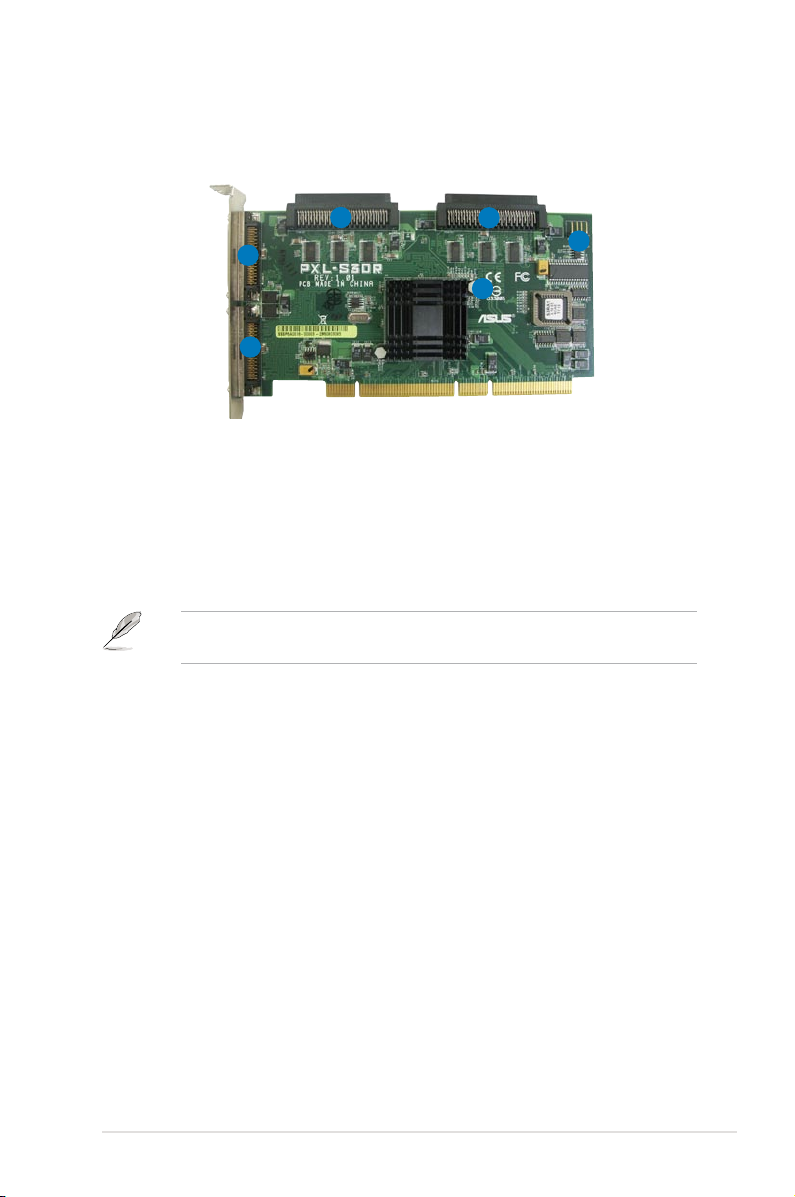
1.3 Card layout
The illustration below shows the major components of the SCSI RAID card.
3
2
4
5
6
1
1. Channel A 68-pin VHDCI SCSI connector
2. Channel B 68-pin VHDCI SCSI connector
3. Channel B 68-pin HD SCSI connector
4. Channel A 68-pin HD SCSI connector
5. Channel A and B activity LED connector
6. SCSI card status LED (lights up to indicate that the card is working normally)
You may connect the HDD activity LED cable to the J1 connector. When
Channel A or Channel B has data access, the LED blinks.
1.4 System requirements
Before you install the PXL-S30R SCSI RAID card, check if the remote server
system meets the following requirements:
• workstation or server motherboard with a PCI-X slot
• SCSI hard disk drives (SCSI cable within 8M)
• Supporting operating system:
Windows: -Win2003 -FUSION-MPT Windows Server 2003 Driver
• Other requirement:
- Appropriate thermal solution
- Certied power supply module
ASUS PXL-S30R 1-3
Page 12

1-4 Chapter 1: Product introduction
Page 13

This chapter provides instructions on setting
up, creating, and conguring RAID sets using
the available utilities.
RAID
conguration
2
Page 14

2.1 Setting up RAID
The RAID card supports RAID 0, RAID 1 and RAID 1E set.
2.1.1 RAID denitions
RAID 0
(Data striping)
data in parallel, interleaved stacks. Two hard disks perform the same work as a
single drive but at a sustained data transfer rate, double that of a single disk alone,
thus improving data access and storage. Use of two new identical hard disk drives
is required for this setup.
RAID 1
(Data mirroring)
drive to a second drive. If one drive fails, the disk array management software
directs all applications to the surviving drive as it contains a complete copy of
the data in the other drive. This RAID conguration provides data protection and
increases fault tolerance to the entire system. Use two new drives or use an
existing drive and a new drive for this setup. The new drive must be of the same
size or larger than the existing drive.
RAID 1-E
secondary (or alternate) copy stored on a different disk. You can use three or more
hard disk drives for this conguration.
(Enhanced RAID 1)
If you want to boot the system from a hard disk drive included in a created RAID
set, copy rst the RAID driver from the support CD to a oppy disk before you
install an operating system to the selected hard disk drive.
2.1.2 Installing hard disk drives
The RAID card supports SCSI for RAID set conguration. For optimal performance,
install identical drives of the same model and capacity when creating a disk array.
To install the SCSI hard disks for RAID conguration:
optimizes two identical hard disk drives to read and write
copies and maintains an identical image of data from one
has a striped layout with each stripe unit having a
1. Install the SCSI hard disks into the drive bays following the instructions in the
system user guide.
2. Connect a SCSI signal cable to the signal connector at the SCSI backplane.
3. Connect a power cable to the power connector on each drive.
2-2 Chapter 2: RAID conguration
Page 15

2.1.3 Flashing RAID card rmware
The PXL-S30R SCSI RAID card supports RAID 0, RAID 1 and RAID 1E solution.
If you need to switch the solution, you need to ash the rmware using the support
CD that comes with the RAID card.
To ash the RAID card rmware in DOS environment:
1. Place the motherboard support CD in the optical drive.
2. Restart the computer, then enter the BIOS Setup.
3. Select the optical drive as the rst boot priority to boot from the support CD.
Save your changes, then exit the BIOS Setup.
4. Restart the computer.
5. Press any key when prompted to boot from CD.
Loading FreeDOS FAT KERNEL GO!
Press any key to boot from CDROM...
The Makedisk menu appears.
A) FreeDOS command prompt
B) Make PXL-S30R RAID Card driver disk for Windows 2000
C) Make PXL-S30R RAID Card driver disk for Windows Server 2003
D) Flash PXL-S30R RAID Card BIOS and Firmware for RAID 0
E) Flash PXL-S30R RAID Card BIOS and Firmware for RAID 1
Please choose A TO E:
6. Select D) or E) to ash the RAID card BIOS and rmware for RAID 0 or
RAID 1/RAID 1E based on your needs, and press <Enter> to start ashing.
ASUS PXL-S30R 2-3
Page 16

2.2 LSI Logic MPT SCSI Setup Utility
The LSI Logic MPT SCSI Setup Utility is an integrated RAID solution that allows
you to create the following RAID set(s) from SCSI hard disk drives supported by
the LSI1030 SCSI controller:
• RAID 1 (Integrated Mirroring)/ RAID 1E (Integrated Mirroring Enhanced)
• RAID 0 (Integrated Striping)
2.2.1 Integrated Mirroring (IM) volume/
Integrated Mirroring Enhanced (IME) volume
Overview
The Integrated Mirroring (IM) feature supports simultaneous mirrored volumes with
two disks (IM). Integrated Mirroring Enhanced (IME) supports three to eight disks,
or seven mirrored disks plus a hot spare disk.
The IM feature supports hot swap capability, so when a disk in an IM volume fails,
you can easily restore the volume, and the swapped disk is automatically remirrored.
Creating Integrated Mirroring volumes
The RAID BIOS setup screens shown in this section are for reference only and
may not exactly match the items on your screen.
To create an IM volume:
1. Turn on the system after installing all SCSI hard disk drives.
2. During POST, press <Ctrl+C> to enter the SCSI conguration utility.
LSI Logic Corp. MPT IS BIOS
MPTBIOS-5.11.01
Copyright 1995-2003 LSI Logic Corp.
Adapter(s) disabled by user
Press Ctrl-C to start LSI Logic Conguration Utility...
2-4 Chapter 2: RAID conguration
Page 17

3. The following screen appears. Select a channel and press <Enter> to enter
the setup.
LSI Logic MPT SCSI Setup Utility Version MPTBIOS-IME-5.10.03
<Boot Adapter List> <Global Properties>
LSI Logic Host Bus Adapters
Adapter PCI Dev/ Port IRQ NVM Boot LSI Logic RAID
BUS Func Number Order Control Status
<1020/1030 2 10> A000 10 Yes 0 Enabled --
<1020/1030 2 11> 9000 11 Yes 1 Enabled --
Esc = Abort/Exit ArrowKeys=Select Item -/+ =Change [Item]
Home/End =Select Item Enter=Execute <Item>
F2 =Menu
The numbers of the channel depend on the controller.
4. The Adapter Properties screen appears. Use the arrow keys to select RAID
Properties, then press <Enter>.
LSI Logic MPT SCSI Setup Utility Version MPTBIOS-IME-5.10.03
Adapters Properties
Adapter PCI Dev/
Bus Func
1020/1030 2 10
<Device Properties>
<RAID Properties> <Synchronize Whole Mirror>
Host SCSI ID [ 7]
SCSI Bus Scan Order [Low to High (0..Max)]
Removable Media Support [None]
CHS Mapping [SCSI Plug and Play Mapping]
Spinup Delay (Secs) [ 2]
Secondary Cluster Server [No]
Termination Control [Auto]
<Restore Defaults>
Esc = Abort/Exit ArrowKeys=Select Item -/+ =Change [Item]
Home/End =Select Item Enter=Execute <Item>
ASUS PXL-S30R 2-5
Page 18

5. The RAID Properties screen shows the disks you can add to make up the
IM/IME volume. Use the arrow key to select a disk, then move the cursor to
the Array Disk? column. To include this disk in the array, press <+> or <->.
You may also specify the Hot Spare disk here. Select the disk, then move the
cursor to the Hot Spare column, then press <+> or <->.
LSI Logic MPT SCSI Setup Utility Version MPTBIOS-IME-5.10.03
RAID Properties Array: -- SCSI ID: -- Size(MB): ------
SCSI Device Identier Array Hot Status Predict Size
ID Disk? Spare Failure (MB)
0 - [No] [---] -------- --- ---- 1 - [No] [---] -------- --- ---- 2 - [No] [---] -------- --- ---- 3 - [No] [---] -------- --- ---- 4 - [No] [---] -------- --- ---- 5 - [No] [---] -------- --- ---- 6 - [No] [---] -------- --- ---- 7 1020/1030 [No] [---] -------- --- -----
8 FUJITSU MAT3073NC 0107 [Yes] [---] Primary --- 70136
9 FUJITSU MAT3073NC 0107 [No] [---] -------- --- 70136
10 FUJITSU MAT3073NC 0107 [No] [---] -------- --- 70136
11 - [No] [---] -------- --- ----12 - [No] [---] -------- --- ----13 SDR GEM318 0 [No] [---] -------- --- ----14 - [No] [---] -------- --- ----15 - [No] [---] -------- --- -----
Esc = Abort/Exit ArrowKeys=Select Item -/+ =Change [Item]
Home/End =Select Item Enter=Execute <Item>
F4=Diagnostic
By default, the Array Disk? eld shows [No] before array creation. This eld is
grayed out under the following conditions:
• The disk does not meet the minimum requirements for use in a RAID array.
• The disk is not large enough to mirror existing data on the primary drive.
• The disk has been selected as the Hot Spare for the RAID array.
• The disk is already part of another array.
For creating IM volume, the system requires two hard disk drives and at least
three hard disk drives for IME volume.
2-6 Chapter 2: RAID conguration
Page 19

6. A conrmation screen appears.
Press <F3> to keep existing data on the rst disk. If you choose this option,
data on the rst disk will be mirrored on the second disk that you will add to
the volume later. Make sure the data you want to mirror is on the rst disk.
Press <Delete> to overwrite any data and create the new IM array.
LSI Logic MPT SCSI Setup Utility Version MPTBIOS-IME-5.10.03
F3 - Keep Data(Create 2 disk array)
Delete-Erase Disk(Create 2 to 6 disk array)
Esc = Abort/Exit ArrowKeys=Select Item -/+ =Change [Item]
Home/End =Select Item Enter=Execute <Item>
F4=Diagnostic
If you select to erase disk, a conrmation screen appears to double-conrm
your selection. Press <Delete> to proceed.
LSI Logic MPT SCSI Setup Utility Version MPTBIOS-IME-5.10.03
WARNING:Data on drive wil be LOST!
Press DELETE if data loss OK or any other key to cancel
Esc = Abort/Exit ArrowKeys=Select Item -/+ =Change [Item]
Home/End =Select Item Enter=Execute <Item>
F4=Diagnostic
7. Repeat steps 4 and 5 to add the second disk to the volume.
ASUS PXL-S30R 2-7
Page 20

8. When done, press <Esc> and select
LSI Logic MPT SCSI Setup Utility Version MPTBIOS-IME-5.10.03
RAID Properties Changed
<Cancel Exit>
Exit the Conguration Utility
<Save changes then exit this menu>
<Discard changes then exit this menu>
Esc = Abort/Exit ArrowKeys=Select Item -/+ =Change [Item]
Home/End =Select Item Enter=Execute <Item>
Save changes then exit this menu.
9. The utility creates the array.
LSI Logic MPT SCSI Setup Utility Version MPTBIOS-IME-5.10.03
Processing...may take up 1 minute
Esc = Abort/Exit ArrowKeys=Select Item -/+ =Change [Item]
Home/End =Select Item Enter=Execute <Item>
F4=Diagnostic
2-8 Chapter 2: RAID conguration
Page 21

2.2.2 Integrated Striping (IS) volume
Overview
The Integrated Striping (IS) feature provides RAID 0 functionality, supporting
volumes with two to eight disks. You may combine an IS volume with an IM
volume.
Creating Integrated Striping volumes
To create an IS volume:
1. Turn on the system after installing all SCSI hard disk drives.
2. During POST, press <Ctrl+C> to enter the SCSI conguration utility.
LSI Logic Corp. MPT IS BIOS
MPTBIOS-5.11.01
Copyright 1995-2003 LSI Logic Corp.
Adapter(s) disabled by user
Press Ctrl-C to start LSI Logic Conguration Utility...
3. The following screen appears. Select a channel and press <Enter> to enter
the setup.
LSI Logic MPT SCSI Setup Utility Version MPTBIOS-IS-5.11.01
<Boot Adapter List> <Global Properties>
LSI Logic Host Bus Adapters
Adapter PCI Dev/ Port IRQ NVM Boot LSI Logic RAID
BUS Func Number Order Control Status
<1020/1030 2 10> A000 10 Yes 0 Enabled --
<1020/1030 2 11> 9000 11 Yes 1 Enabled --
Esc = Abort/Exit ArrowKeys=Select Item -/+ =Change [Item]
Home/End =Select Item Enter=Execute <Item>
F2 =Menu
The numbers of the channel depend on the controller.
ASUS PXL-S30R 2-9
Page 22

4. The Adapter Properties screen appears Use the arrow keys to select RAID
Properties, then press <Enter>.
LSI Logic MPT SCSI Setup Utility Version MPTBIOS-IS-5.10.03
Adapters Properties
Adapter PCI Dev/
Bus Func
1020/1030 2 10
<Device Properties>
<RAID Properties> <Synchronize Whole Mirror>
Host SCSI ID [ 7]
SCSI Bus Scan Order [Low to High (0..Max)]
Removable Media Support [None]
CHS Mapping [SCSI Plug and Play Mapping]
Spinup Delay (Secs) [ 2]
Secondary Cluster Server [No]
Termination Control [Auto]
<Restore Defaults>
Esc = Abort/Exit ArrowKeys=Select Item -/+ =Change [Item]
Home/End =Select Item Enter=Execute <Item>
5. The RAID Properties screen shows the disks you can add to make up the
IS volume. Use the arrow key to select a disk, then move the cursor to the
Array Disk? column. To include this disk in the array, press <+> or <->.
LSI Logic MPT SCSI Setup Utility Version MPTBIOS-IS-5.11.01
RAID Properties Array: IS SCSI ID: 8 Size(MB): 140016
SCSI Device Identier Array Status Predict Size
ID Disk? Failure (MB)
0 - [No] -------- --- ---- 1 - [No] -------- --- ---- 2 - [No] -------- --- ---- 3 - [No] -------- --- ---- 4 - [No] -------- --- ---- 5 - [No] -------- --- ---- 6 - [No] -------- --- ---- 7 1020/1030 [No] -------- --- -----
8 FUJITSU MAT3073NC 0107 [Yes] -------- --- 70136
9 FUJITSU MAT3073NC 0107 [Yes] -------- --- 70136
10 FUJITSU MAT3073NC 0107 [No] -------- --- 70136
11 - [No] -------- --- ----12 - [No] -------- --- ----13 SDR GEM318 0 [No] -------- --- ----14 - [No] -------- --- ----15 - [No] -------- --- -----
Esc = Abort/Exit ArrowKeys=Select Item -/+ =Change [Item]
Home/End =Select Item Enter=Execute <Item>
F4=Diagnostic
By default, the Array Disk? eld shows [No] before array creation. This eld is
grayed out under the following conditions:
• The disk does not meet the minimum requirements for use in a RAID array.
• The disk is already part of another array.
2-10 Chapter 2: RAID conguration
Page 23

6. Repeat steps 4 and 5 to add the second disk to the volume.
7. When done, press <Esc> and select
LSI Logic MPT SCSI Setup Utility Version MPTBIOS-IS-5.11.01
RAID Properties Changed
<Cancel Exit>
Exit the Conguration Utility
<Save changes then exit this menu>
<Discard changes then exit this menu>
Esc = Abort/Exit ArrowKeys=Select Item -/+ =Change [Item]
Home/End =Select Item Enter=Execute <Item>
Save changes then exit this menu.
8. The utility creates the array.
LSI Logic MPT SCSI Setup Utility Version MPTBIOS-IS-5.11.01
Processing...may take up 1 minute
Esc = Abort/Exit ArrowKeys=Select Item -/+ =Change [Item]
Home/End =Select Item Enter=Execute <Item>
F4=Diagnostic
ASUS PXL-S30R 2-11
Page 24

2.2.3 Managing Arrays
The LSI Logic MPT SCSI Setup Utility allows you to perform other tasks related to
conguring and maintaining IM volumes.
Refer to this section to view volume properties, manage the hot spare disk,
synchronize the array, activate the array, and delete the array.
Viewing volume properties
To view volume properties:
1. On the main menu, select
LSI Logic MPT SCSI Setup Utility Version MPTBIOS-IME-5.10.03
Adapters Properties
Adapter PCI Dev/
Bus Func
1020/1030 2 10
<Device Properties>
<RAID Properties> <Synchronize Whole Mirror>
Host SCSI ID [ 7]
SCSI Bus Scan Order [Low to High (0..Max)]
Removable Media Support [None]
CHS Mapping [SCSI Plug and Play Mapping]
Spinup Delay (Secs) [ 2]
Secondary Cluster Server [No]
Termination Control [Auto]
<Restore Defaults>
Esc = Abort/Exit ArrowKeys=Select Item -/+ =Change [Item]
Home/End =Select Item Enter=Execute <Item>
2.
Here you can view properties of the RAID array(s) created. If you have
RAID Properties.
congured a hot spare, it will also be listed. if you created more than one
array, you may view the next array by pressing <F2> and select <Next Array>
from the menu.
LSI Logic MPT SCSI Setup Utility Version MPTBIOS-IME-5.10.03
<Next Array> <Delete Array> <Add/Delete Hot Spare> <Activate Array>
RAID Properties Array: IM SCSI ID: 8 Size(MB): 70008
SCSI Device Identier Array Hot Status Predict Size
ID Disk? Spare Failure (MB)
8 FUJITSU MAT3073NC 0107 Yes No Primary No 70008
9 FUJITSU MAT3073NC 0107 Yes No Out of Sync No 70008
10 FUJITSU MAT3073NC 0107 --- No Ok No 70008
Esc=Abort/Exit ArrowKeys=Select Item -/+ =Change [Item]
Home/End =Select Item Enter=Execute <Item>
F2 =Menu
2-12 Chapter 2: RAID conguration
Page 25

Adding or deleting hot spares
You may congure one disk as a global hot spare to protect critical data on the IM
volume(s). You may create the hot spare disk at the same time you create the IM
volume. Refer to this section when adding a hot spare disk on an existing volume.
If a disk on an IM volume fails, the utility automatically rebuilds the failed disk
data on the hot spare. When the failed disk is replaced, the utility assigns the
replacement as the new hot spare.
To create a hot spare:
1. Follow steps 1~2 of the section
Viewing volume properties.
2. From the screen, press <F2> to select <Add/Delete Hot Spare>.
3. Use the arrow key to select the disk you would like to congure as hot spare,
then move the cursor to the Hot Spare column. Press <+> or <-> and the
Hot Spare column eld now shows Yes.
LSI Logic MPT SCSI Setup Utility Version MPTBIOS-IME-5.10.03
<Next Array> <Delete Array> <Add/Delete Hot Spare> <Activate Array>
RAID Properties Array: IM SCSI ID: 8 Size(MB): 70008
SCSI Device Identier Array Hot Status Predict Size
ID Disk? Spare Failure (MB)
8 FUJITSU MAT3073NC 0107 Yes No Primary No 70008
9 FUJITSU MAT3073NC 0107 Yes No Out of Sync No 70008
10 FUJITSU MAT3073NC 0107 --- Yes Ok No 70008
Esc=Abort/Exit ArrowKeys=Select Item -/+ =Change [Item]
Home/End =Select Item Enter=Execute <Item>
F2 =Menu
ASUS PXL-S30R 2-13
Page 26

Deleting an array
• You cannot recover lost data if you delete an array. Make sure you back up
important data before deleting an array.
• If you delete an IM (RAID 1) volume, the data is preserved on the primary
disk.
To delete an array:
1. Follow steps 1~2 of the section
Viewing volume properties.
2. From the screen, press <F2> to select <Activate Array>.
LSI Logic MPT SCSI Setup Utility Version MPTBIOS-IME-5.10.03
<Next Array> <Delete Array> <Add/Delete Hot Spare> <Activate Array>
RAID Properties Array: IM SCSI ID: 8 Size(MB): 70008
SCSI Device Identier Array Hot Status Predict Size
ID Disk? Spare Failure (MB)
8 FUJITSU MAT3073NC 0107 Yes No Primary No 70008
9 FUJITSU MAT3073NC 0107 Yes No Out of Sync No 70008
10 FUJITSU MAT3073NC 0107 --- Yes Ok No 70008
Esc=Abort/Exit ArrowKeys=Select Item -/+ =Change [Item]
Home/End =Select Item Enter=Execute <Item>
F2 =Menu
3. Press <Y> to delete, or <N> to cancel.
2-14 Chapter 2: RAID conguration
Page 27

Activating an array
If an array is removed from one controller/computer or moved to another, the
array is considered inactive. When you add the array back to the system, you may
reactivate the array.
To activate the array:
1. Follow steps 1~2 of the section
Viewing volume properties.
2. From the screen, press <F2> to select <Activate Array>.
LSI Logic MPT SCSI Setup Utility Version MPTBIOS-IME-5.10.03
<Next Array> <Delete Array> <Add/Delete Hot Spare> <Activate Array>
RAID Properties Array: IM SCSI ID: 8 Size(MB): 70008
SCSI Device Identier Array Hot Status Predict Size
ID Disk? Spare Failure (MB)
8 FUJITSU MAT3073NC 0107 Yes No Primary No 70008
9 FUJITSU MAT3073NC 0107 Yes No Out of Sync No 70008
10 FUJITSU MAT3073NC 0107 --- Yes Ok No 70008
Esc=Abort/Exit ArrowKeys=Select Item -/+ =Change [Item]
Home/End =Select Item Enter=Execute <Item>
F2 =Menu
3. Press <Y> to activate, or <N> to cancel.
Synchronizing the array
Synchronizing the array allows the utility to resynchronize data on the mirrored
disk in the array. This procedure is seldom required because data synchronization
is automatically done during normal operation. To synchronize the array, select
Synchronize Whole Mirror from the main menu to start the synchronization.
LSI Logic MPT SCSI Setup Utility Version MPTBIOS-IME-5.10.03
Adapters Properties
Adapter PCI Dev/
Bus Func
1020/1030 2 10
<Device Properties>
<RAID Properties> <Synchronize Whole Mirror>
Host SCSI ID [ 7]
SCSI Bus Scan Order [Low to High (0..Max)]
Removable Media Support [None]
CHS Mapping [SCSI Plug and Play Mapping]
Spinup Delay (Secs) [ 2]
Secondary Cluster Server [No]
Termination Control [Auto]
<Restore Defaults>
Esc = Abort/Exit ArrowKeys=Select Item -/+ =Change [Item]
Home/End =Select Item Enter=Execute <Item>
ASUS PXL-S30R 2-15
Page 28

2.2.4 Selecting a boot disk
You can select a boot disk in the rst screen you enter SCSI Setup Utility. This
disk is then moved to scan ID 0 on the next boot, and remains at this position.
This makes it easier to set BIOS boot device options and to keep the boot device
constant during device additions and removals. There can be only one boot disk.
Follow these steps to select a boot disk:
1. After enter the SCSI Setup Utility, press <F2> to select <Boot Adapter List>.
LSI Logic MPT SCSI Setup Utility Version MPTBIOS-IS-5.11.01
<Boot Adapter List> <Global Properties>
LSI Logic Host Bus Adapters
Adapter PCI Dev/ Port IRQ NVM Boot LSI Logic RAID
BUS Func Number Order Control Status
<1020/1030 2 10> A000 10 Yes 0 Enabled --
<1020/1030 2 11> 9000 11 Yes 1 Enabled --
Esc = Abort/Exit ArrowKeys=Select Item -/+ =Change [Item]
Home/End =Select Item Enter=Execute <Item>
F2 =Menu
2. From the Boot Adapter List screen, move the cursor to highlight the Boot
Order column or Next Boot column and press <+> or <-> to congure the
boot adapters. Press <Insert> to add an adapter and <Delete> to remove an
adapter if needed.
LSI Logic MPT SCSI Setup Utility Version MPTBIOS-IME-5.10.03
Boot Adapter List
Insert=Add an adapter Delete=Remove an adapter
Adapter PCI Dev/ Boot Current Next
Bus Func Order Status Boot
1020/1030 2 10 [0] On [On]
1020/1030 2 10 [1] On [On]
Hit Insert to select an adapter from this list:
<1020/1030 2 10>
<1020/1030 2 11>
Esc = Abort/Exit ArrowKeys=Select Item -/+ =Change [Item]
Home/End =Select Item Enter=Execute <Item>
2-16 Chapter 2: RAID conguration
Page 29

2.2.5 Global Properties
After entering the SCSI Setup Utility screen, press <F2> and select <Global
Properties> from the menu. The Global Properties menu allows you to change
related settings.
LSI Logic MPT SCSI Setup Utility Version MPTBIOS-IME-5.10.03
Global Properties
Pause When Boot Alert Displayed [No]
Boot Information Display Mode [Verbose]
Negotiate with devices [Supported]
Video Mode [Color]
Support Interrupt [Hook interrupt, the
default]
Disable Integrated RAID [No]
<Restore Defaults>
Esc = Abort/Exit ArrowKeys=Select Item -/+ =Change [Item]
Home/End =Select Item Enter=Execute <Item>
Pause When Boot Alert Displayed
Sets whether to pause or not when the boot alert displays.
Conguration options: [Yes] [No]
LSI Logic MPT SCSI Setup Utility Version MPTBIOS-IME-5.10.03
Global Properties
Pause When Boot Alert Displayed [No]
Boot Information Display Mode [Verbose]
Negotiate with devices [Supported]
Video Mode [Color]
Support Interrupt [Hook interrupt, the default]
Disable Integrated RAID [No]
<Restore Defaults>
Esc = Abort/Exit ArrowKeys=Select Item -/+ =Change [Item]
Home/End =Select Item Enter=Execute <Item>
ASUS PXL-S30R 2-17
Page 30

Boot Information Display Mode
Sets the disk information display mode.
Conguration options: [Verbose] [Terse]
LSI Logic MPT SCSI Setup Utility Version MPTBIOS-IME-5.10.03
Global Properties
Pause When Boot Alert Displayed [No]
Boot Information Display Mode [Verbose]
Negotiate with devices [Supported]
Video Mode [Color]
Support Interrupt [Hook interrupt, the default]
Disable Integrated RAID [No]
<Restore Defaults>
Esc = Abort/Exit ArrowKeys=Select Item -/+ =Change [Item]
Home/End =Select Item Enter=Execute <Item>
Negotiate with devices
Conguration options: [Supported] [All]
LSI Logic MPT SCSI Setup Utility Version MPTBIOS-IME-5.10.03
Global Properties
Pause When Boot Alert Displayed [No]
Boot Information Display Mode [Verbose]
Negotiate with devices [Supported]
Video Mode [Color]
Support Interrupt [Hook interrupt, the default]
Disable Integrated RAID [No]
<Restore Defaults>
Esc = Abort/Exit ArrowKeys=Select Item -/+ =Change [Item]
Home/End =Select Item Enter=Execute <Item>
2-18 Chapter 2: RAID conguration
Page 31

Video Mode
Conguration options: [Color] [Monochrome]
LSI Logic MPT SCSI Setup Utility Version MPTBIOS-IME-5.10.03
Global Properties
Pause When Boot Alert Displayed [No]
Boot Information Display Mode [Verbose]
Negotiate with devices [Supported]
Video Mode [Color]
Support Interrupt [Hook interrupt, the default]
Disable Integrated RAID [No]
<Restore Defaults>
Esc = Abort/Exit ArrowKeys=Select Item -/+ =Change [Item]
Home/End =Select Item Enter=Execute <Item>
Support Interrupt
Conguration options: [Hook interrupt, the Default] [Bypass interrupt hook]
LSI Logic MPT SCSI Setup Utility Version MPTBIOS-IME-5.10.03
Global Properties
Pause When Boot Alert Displayed [No]
Boot Information Display Mode [Verbose]
Negotiate with devices [Supported]
Video Mode [Color]
Support Interrupt [Hook interrupt, the default]
Disable Integrated RAID [No]
<Restore Defaults>
Esc = Abort/Exit ArrowKeys=Select Item -/+ =Change [Item]
Home/End =Select Item Enter=Execute <Item>
ASUS PXL-S30R 2-19
Page 32

Disabled Integrated RAID
Conguration options: [No] [Yes]
LSI Logic MPT SCSI Setup Utility Version MPTBIOS-IME-5.10.03
Global Properties
Pause When Boot Alert Displayed [No]
Boot Information Display Mode [Verbose]
Negotiate with devices [Supported]
Video Mode [Color]
Support Interrupt [Hook interrupt, the default]
Disable Integrated RAID [No]
<Restore Defaults>
Esc = Abort/Exit ArrowKeys=Select Item -/+ =Change [Item]
Home/End =Select Item Enter=Execute <Item>
Restore Defaults
This option allows you to discard the selections you made and restore the system
defaults.
LSI Logic MPT SCSI Setup Utility Version MPTBIOS-IME-5.10.03
Global Properties
Pause When Boot Alert Displayed [No]
Boot Information Display Mode [Verbose]
Negotiate with devices [Supported]
Video Mode [Color]
Support Interrupt [Hook interrupt, the default]
Disable Integrated RAID [No]
<Restore Defaults>
Esc = Abort/Exit ArrowKeys=Select Item -/+ =Change [Item]
Home/End =Select Item Enter=Execute <Item>
2-20 Chapter 2: RAID conguration
Page 33

This chapter provides instructions for
updating the latest drivers in Windows®
Server 2003.
Driver update
3
Page 34

3.1 RAID controller driver update
After creating the RAID sets for your server system, you are now ready to install
an operating system to the independent hard disk drive or bootable array. This
part provides instructions on how to update the RAID controller drivers after OS
installation.
3.1.1 Windows® Server 2003 OS
To update the RAID controller driver after installing Windows
®
Server 2003 OS:
1. Right-click
2. Click the
3. Doube-click one of the LSI Logic PCI-X Ultra320 SCSI Host Adapter.
My Computer on the desktop and select Properties.
Hardware tab on the top, then press the Device Manager button.
3-2 Chapter 3: Driver update
Page 35

4. Click the Driver tab on the top, then click Update Driver.
5. Toggle No, not this time, then click Next to continue.
6. Toggle
ASUS PXL-S30R 3-3
Install from a list or specic location, then click Next to continue.
Page 36

7. Toggle Don’t choose. I will choose the driver to install, then click Next to
continue.
8. Highlight
LSI Logic PCI-X Ultra320 SCSI Host Adapter, then click Have
Disk.
9. Select from the drop-down menu and locate the driver.
3-4 Chapter 3: Driver update
Page 37

10. Click Next to start updating the driver.
11. After completing driver update, click
Finish to close the wizard.
12. Repeat the previous instructions to update the driver of another channel.
ASUS PXL-S30R 3-5
Page 38

3.2 Management applications and utilities
installation
The support CD that came with the SCSI RAID card package contains the drivers,
that you can install to avail all motherboard features.
The contents of the support CD are subject to change at any time without
notice. Visit the ASUS website (www.asus.com) for updates.
3.2.1 Running the support CD
Place the support CD to the optical drive. The CD automatically displays the
Drivers menu if Autorun is enabled in your computer.
If Autorun is NOT enabled in your computer, browse the contents of the support
CD to locate the le ASSETUP.EXE from the BIN folder. Double-click the
ASSETUP.EXE to run the CD.
3.2.2 Drivers menu
The Drivers menu shows the available device drivers if the system detects installed
devices. Install the necessary drivers to activate the devices.
The screen display and driver options may vary under different operating
system versions.
3-6 Chapter 3: Driver update
Page 39

3.2.3 Contact information
Click the Contact tab to display the ASUS contact information. You can also nd
this information on the inside front cover of this user guide.
ASUS PXL-S30R 3-7
Page 40

3-8 Chapter 3: Driver update
 Loading...