

Page 1
PW201 LCD Monitor
User Guide
Page 2

E2396E2396
E2396
E2396E2396
First Edition V1First Edition V1
First Edition V1
First Edition V1First Edition V1
February 2006February 2006
February 2006
February 2006February 2006
Copyright © 2006 ASUSTeK COMPUTER INC. All Rights Reserved.Copyright © 2006 ASUSTeK COMPUTER INC. All Rights Reserved.
Copyright © 2006 ASUSTeK COMPUTER INC. All Rights Reserved.
Copyright © 2006 ASUSTeK COMPUTER INC. All Rights Reserved.Copyright © 2006 ASUSTeK COMPUTER INC. All Rights Reserved.
No part of this manual, including the products and software described in it, may be reproduced,
transmitted, transcribed, stored in a retrieval system, or translated into any language in any form
or by any means, except documentation kept by the purchaser for backup purposes, without the
express written permission of ASUSTeK COMPUTER INC. (“ASUS”).
Product warranty or service will not be extended if: (1) the product is repaired, modified or
altered, unless such repair, modification of alteration is authorized in writing by ASUS; or (2) the
serial number of the product is defaced or missing.
ASUS PROVIDES THIS MANUAL “AS IS” WITHOUT WARRANTY OF ANY KIND, EITHER EXPRESS OR
IMPLIED, INCLUDING BUT NOT LIMITED TO THE IMPLIED WARRANTIES OR CONDITIONS OF
MERCHANTABILITY OR FITNESS FOR A PARTICULAR PURPOSE. IN NO EVENT SHALL ASUS, ITS
DIRECTORS, OFFICERS, EMPLOYEES OR AGENTS BE LIABLE FOR ANY INDIRECT, SPECIAL,
INCIDENTAL, OR CONSEQUENTIAL DAMAGES (INCLUDING DAMAGES FOR LOSS OF PROFITS, LOSS
OF BUSINESS, LOSS OF USE OR DATA, INTERRUPTION OF BUSINESS AND THE LIKE), EVEN IF ASUS
HAS BEEN ADVISED OF THE POSSIBILITY OF SUCH DAMAGES ARISING FROM ANY DEFECT OR
ERROR IN THIS MANUAL OR PRODUCT.
SPECIFICATIONS AND INFORMATION CONTAINED IN THIS MANUAL ARE FURNISHED FOR
INFORMATIONAL USE ONLY, AND ARE SUBJECT TO CHANGE AT ANY TIME WITHOUT NOTICE, AND
SHOULD NOT BE CONSTRUED AS A COMMITMENT BY ASUS. ASUS ASSUMES NO RESPONSIBILITY
OR LIABILITY FOR ANY ERRORS OR INACCURACIES THAT MAY APPEAR IN THIS MANUAL,
INCLUDING THE PRODUCTS AND SOFTWARE DESCRIBED IN IT.
Products and corporate names appearing in this manual may or may not be registered
trademarks or copyrights of their respective companies, and are used only for identification or
explanation and to the owners’ benefit, without intent to infringe.
iiii
ii
iiii
Page 3

Table of contents
Notices ................................................................................................ iv
Safety information ............................................................................... v
Care and Cleaning ............................................................................... vi
Package contents ............................................................................. viii
Chapter 1:Chapter 1:
Chapter 1:
Chapter 1:Chapter 1:
1.1 Welcome! .............................................................................. 1-2
1.2 Features ............................................................................... 1-2
1.3 Monitor introduction ............................................................. 1-3
Chapter 2:Chapter 2:
Chapter 2:
Chapter 2:Chapter 2:
2.1 Unfolding the monitor .......................................................... 2-2
2.2 Connecting the cables .......................................................... 2-2
2.3 Turning on the monitor ........................................................ 2-4
2.4 Adjusting the tilt .................................................................. 2-5
2.5 Detaching the stand (for VESA wall mount) ........................ 2-6
Chapter 3:Chapter 3:
Chapter 3:
Chapter 3:Chapter 3:
3.1 OSD (On-Screen Display) menu ............................................ 3-2
Product introductionProduct introduction
Product introduction
Product introductionProduct introduction
SetupSetup
Setup
SetupSetup
General InstructionGeneral Instruction
General Instruction
General InstructionGeneral Instruction
3.1.1 Configuring the OSD ............................................... 3-2
3.1.2 OSD function introduction ...................................... 3-2
®
3.2 Pivot
3.3 Using the built-in webcam .................................................... 3-7
3.3.1 Hardware ................................................................ 3-7
3.3.2 Software ................................................................. 3-7
3.4 LifeFrame software .............................................................. 3-8
3.4.1 Introduction and installation instruction ................. 3-8
3.4.2 Main screen ............................................................. 3-9
3.4.3 Preview mode ....................................................... 3-10
3.4.4 Status bar ............................................................. 3-10
3.4.5 Operating area ...................................................... 3-11
3.4.6 Enhance ................................................................3-12
Pro software .............................................................. 3-6
iiiiii
iii
iiiiii
Page 4

3.4.7 Effects .................................................................. 3-13
3.4.8 Setup - basic setup .............................................. 3-14
3.4.9 Setup - capture format ........................................ 3-15
3.4.10 Setup - capture mode .......................................... 3-16
3.5 Troubleshooting (FAQ) ....................................................... 3-17
3.6 PW201 specification summary ........................................... 3-18
3.7 Supported operating modes ............................................... 3-20
iviv
iv
iviv
Page 5

Notices
Federal Communications Commission StatementFederal Communications Commission Statement
Federal Communications Commission Statement
Federal Communications Commission StatementFederal Communications Commission Statement
This device complies with Part 15 of the FCC Rules. Operation is subject to
the following two conditions:
• This device may not cause harmful interference, and
• This device must accept any interference received including interference
that may cause undesired operation.
This equipment has been tested and found to comply with the limits for a
Class B digital device, pursuant to Part 15 of the FCC Rules. These limits are
designed to provide reasonable protection against harmful interference in a
residential installation. This equipment generates, uses and can radiate radio
frequency energy and, if not installed and used in accordance with
manufacturer’s instructions, may cause harmful interference to radio
communications. However, there is no guarantee that interference will not
occur in a particular installation. If this equipment does cause harmful
interference to radio or television reception, which can be determined by
turning the equipment off and on, the user is encouraged to try to correct
the interference by one or more of the following measures:
• Reorient or relocate the receiving antenna.
• Increase the separation between the equipment and receiver.
• Connect the equipment to an outlet on a circuit different from that to
which the receiver is connected.
• Consult the dealer or an experienced radio/TV technician for help.
® ®
®
As an Energy StarAs an Energy Star
As an Energy Star
As an Energy StarAs an Energy Star
this product meets the Energy Starthis product meets the Energy Star
this product meets the Energy Star
this product meets the Energy Starthis product meets the Energy Star
efficiency.efficiency.
efficiency.
efficiency.efficiency.
Canadian Department of Communications StatementCanadian Department of Communications Statement
Canadian Department of Communications Statement
Canadian Department of Communications StatementCanadian Department of Communications Statement
® ®
Partner, our company has determined thatPartner, our company has determined that
Partner, our company has determined that
Partner, our company has determined thatPartner, our company has determined that
® ®
®
® ®
guidelines for energyguidelines for energy
guidelines for energy
guidelines for energyguidelines for energy
This digital apparatus does not exceed the Class B limits for radio noise
emissions from digital apparatus set out in the Radio Interference
Regulations of the Canadian Department of Communications.
This class B digital apparatus complies with CanadianThis class B digital apparatus complies with Canadian
This class B digital apparatus complies with Canadian
This class B digital apparatus complies with CanadianThis class B digital apparatus complies with Canadian
ICES-003.ICES-003.
ICES-003.
ICES-003.ICES-003.
vv
v
vv
Page 6

Safety information
• Before setting up the monitor, carefully read all the documentation that
came with the package.
• To prevent fire or shock hazard, never expose the monitor to rain or
moisture.
• Never try to open the monitor cabinet. The dangerous high voltages
inside the monitor may result in serious physical injury.
• If the power supply is broken, do not try to fix it by yourself. Contact a
qualified service technician or your retailer.
• Before using the product, make sure all cables are correctly connected
and the power cables are not damaged. If you detect any damage,
contact your dealer immediately.
• Slots and openings on the back or top of the cabinet are provided for
ventilation. Do not block these slots. Never place this product near or
over a radiator or heat source unless proper ventilation is provided.
• The monitor should be operated only from the type of power source
indicated on the label. If you are not sure of the type of power supply to
your home, consult your dealer or local power company.
• Use the appropriate power plug which complies with your local power
standard.
• Do not overload power strips and extention cords. Overloading can result
in fire or electric shock.
• Avoid dust, humidity, and temperature extremes. Do not place the
monitor in any area where it may become wet. Place the monitor on a
stable surface.
• Unplug the unit during a lightning storm or if it will not be used for a long
period of time. This will protect the monitor from damage due to power
surges.
• Never push objects or spill liquid of any kind into the slots on the monitor
cabinet.
• To ensure satisfactory operation, use the monitor only with UL listed
computers which have appropriate configured receptacles marked
between 100-240V AC.
• If you encounter technical problems with the monitor, contact a qualified
service technician or your retailer.
vivi
vi
vivi
Page 7

Care and Cleaning
• Before you lift or reposition your monitor, it is better to disconnect the
cables and power cord. Follow the correct lifting techniques when
positioning the monitor. When lifting or carrying the monitor, grasp the
edges of the monitor. Do not lift the display by the stand or the cord.
• Cleaning. Turn your monitor off and unplug the power cord. Clean the
monitor surface with a lint-free, non-abrasive cloth. Stubborn stains may
be removed with a cloth dampened with mild cleaner.
• Avoid using a cleaner containing alcohol or acetone. Use a cleaner
intended for use with the LCD. Never spray cleaner directly on the
screen, as it may drip inside the monitor and cause an electric shock.
The following symptoms are normal with the monitor:The following symptoms are normal with the monitor:
The following symptoms are normal with the monitor:
The following symptoms are normal with the monitor:The following symptoms are normal with the monitor:
• The screen may flicker during the initial use due to the nature of the
fluorescent light. Turn off the Power Switch and turn it on again to make
sure that the flicker disappears.
• You may find slightly uneven brightness on the screen depending on the
desktop pattern you use.
• When the same image is displayed for hours, an afterimage of the
previous screen may remain after switching the image. The screen will
recover slowly or you can turn off the Power Switch for hours.
• When the screen becomes black or flashes, or cannot work anymore,
contact your dealer or service center to fix it. Do not repair the screen
by yourself!
Conventions used in this guideConventions used in this guide
Conventions used in this guide
Conventions used in this guideConventions used in this guide
WARNING: WARNING:
WARNING: Information to prevent injury to yourself when trying to
WARNING: WARNING:
complete a task.
CAUTION: CAUTION:
CAUTION: Information to prevent damage to the components
CAUTION: CAUTION:
when trying to complete a task.
IMPORTANT: IMPORTANT:
IMPORTANT: Information that you MUST follow to complete a
IMPORTANT: IMPORTANT:
task.
NOTE: NOTE:
NOTE: Tips and additional information to aid in completing a task.
NOTE: NOTE:
viivii
vii
viivii
Page 8

Where to find more informationWhere to find more information
Where to find more information
Where to find more informationWhere to find more information
Refer to the following sources for additional information and for product
and software updates.
1.1.
ASUS websitesASUS websites
1.
ASUS websites
1.1.
ASUS websitesASUS websites
The ASUS websites worldwide provide updated information on ASUS
hardware and software products. Refer to http://www.asus.com
2.2.
Optional documentationOptional documentation
2.
Optional documentation
2.2.
Optional documentationOptional documentation
Your product package may include optional documentation, such as
warranty card, that may have been added by your dealer. These
documents are not part of the standard package.
viiiviii
viii
viiiviii
Page 9

Package contents
Check your PW201 LCD package for the following items:
LCD monitor
Quick Start Guide
Support CD
1 x Power cord
1 x Power adapter
1 x VGA-Audio-USB 3-in-1 cable
1 x DVI cable
1 x RCA cable
1 x Rear connector cover
If any of the above items is damaged or missing, contact your retailer
immediately.
ixix
ix
ixix
Page 10

xx
x
xx
Page 11

Chapter 1
This chapter gives a general description of
the ASUS LCD monitor PW201. The chapter
lists the monitor features including
introduction on the front and rear panels as
well as the side view.
Product introduction
Page 12

1.1 Welcome!
Thank you for purchasing the ASUS
®
PW201 LCD monitor!
The latest widescreen LCD monitor from ASUS provides a crisper, broader,
and brighter display, plus a host of features that enhance your viewing
®
experience. You can turn the ASUS
PW201 LCD monitor counterclockwise
for portrait orientation, giving you a full view of documents and web pages,
and saving you the trouble of having to scroll the bar while you read or surf
the Internet. The PW201 also features a rotating swivel, adjustable tilt and
height, and the glare panel that provides clearer and more vivid visual
experience. The built-in 1.3 mega-pixel webcam on top of the LCD panel
has both video recording and snapshot functions, allowing you to capture
images, create videos, or hold a video conference! You can also link all
kinds of USB devices easily with the accessible USB ports on the left side of
the monitor.
Equipped with S-Video, Video, and Component inputs, the PW201 turns to
be a multi-function monitor ready for all kinds of video applications such as
video game console, DVD player, DV camcorder. Adding to the elegance
and stylish functionality of the PW201 are smart sensor buttons on the
front panel, which are shown in weak LED lights until you touch them.
With these features, you can enjoy the convenience and delightful visual
experience that the PW201 brings you!
1.2 Features
• 20" widescreen LCD monitor
• Recommended resolution: 1680 X 1050
• Anti-reflection glare type panel
• 8ms (grey to grey) quick response time
• 3 USB 2.0 ports
• VGA/DVI/Video/S-Video/Component inputs
• Built-in 1.3 mega-pixel webcam
• SPLENDID™ Video Intelligence Technology
• 5 Video preset modes switched by hotkey
• 3 Skin-tones selection
• Flexible display orientation including portrait/landscape
• Tilt/height adjustment
• Swivel/90º rotation
1-21-2
1-2
1-21-2
• Kensington security lock
• 3W x 2 Stereo speakers and earphone output
®
• Microsoft
Windows 2000/XP compliance
Chapter 1: Product introductionChapter 1: Product introduction
Chapter 1: Product introduction
Chapter 1: Product introductionChapter 1: Product introduction
Page 13
• VESA Display Data Channel DDC2B compliance
• VESA wall mount compliance (100 x 100 mm)
®
• EPA ENERGY STAR
and ergonomic design
• Touch sensor buttons
• RoHS compliance
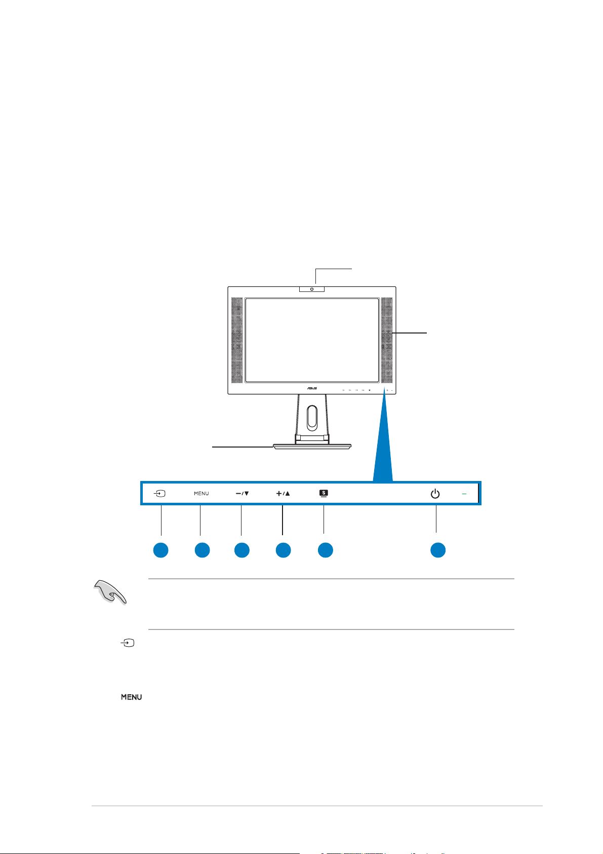
1.3 Monitor introduction
Front viewFront view
Front view
Front viewFront view
Webcam
Stereo
Speaker
Stand
11
1
1.
11
The touch sensors are sensitive. Slightly touch the function you want to
enable. Do not press the front panel too hard to prevent damage to the
panel and the sensors.
Sensor:Sensor:
Sensor:
Sensor:Sensor:
22
2
22
33
3
33
44
4
44
55
5
55
66
6
66
• This is a hotkey for the input sources. Touch this sensor to select
the input source you need.
2.
Sensor:Sensor:
Sensor:
Sensor:Sensor:
• Touch this sensor to enter/select the icon (function) highlighted
while the OSD menu is activated.
ASUS LCD Monitor PW201ASUS LCD Monitor PW201
ASUS LCD Monitor PW201
ASUS LCD Monitor PW201ASUS LCD Monitor PW201
1-31-3
1-3
1-31-3
Page 14
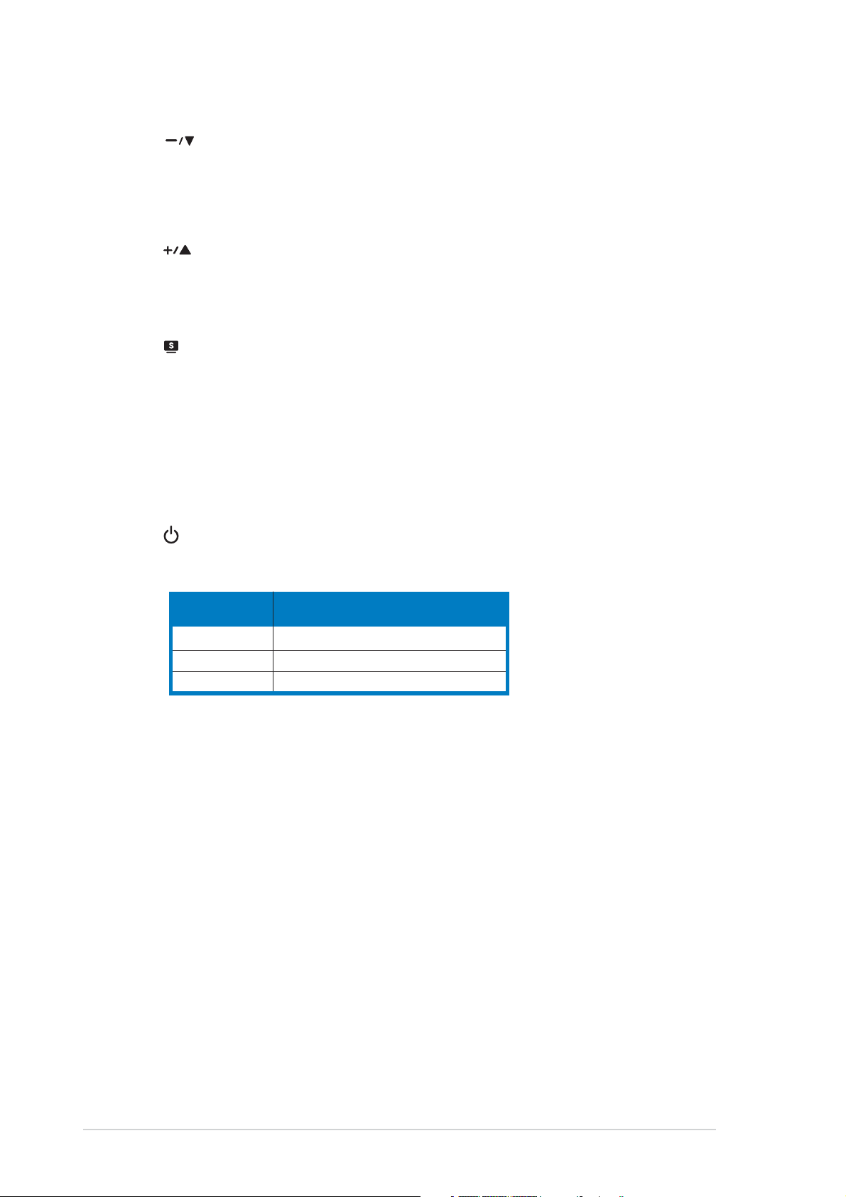
3.
Sensor:Sensor:
Sensor:
Sensor:Sensor:
••
• Touch this sensor to decrease the value of the function selected
••
or move to the previous function.
• This is also a hotkey for Volume adjustment.
4.
Sensor: Sensor:
Sensor:
Sensor: Sensor:
••
• Touch this sensor to increase the value of the function selected
••
or move to the next function.
• This is also a hotkey for Brightness adjustment.
5.
Sensor: Sensor:
Sensor:
Sensor: Sensor:
• Use this hotkey to switch from five video preset modes (Game
Mode, Night View Mode, Scenery Mode, Standard Mode, Theater
Mode) with SPLENDID™ Video Intelligence Technology.
• Touch this sensor exit the OSD menu or go back to the previous
menu as the OSD menu is active.
• Touch this sensor for 2 to 4 seconds to automatically adjust the
image to its optimized position, clock, and phase.
Power sensor/indicator Power sensor/indicator
6.
Power sensor/indicator
Power sensor/indicator Power sensor/indicator
• Touch this sensor to turn the monitor on/off.
Status Description Status Description
Status Description
Status Description Status Description
Blue ON
Amber Standby mode
OFF OFF
1-41-4
1-4
1-41-4
Chapter 1: Product introductionChapter 1: Product introduction
Chapter 1: Product introduction
Chapter 1: Product introductionChapter 1: Product introduction
Page 15

Rear viewRear view
Rear view
Rear viewRear view
Kensington lock
33
3
11
1
11
DC-in port. DC-in port.
1.
DC-in port. This port connects the power connector from the
DC-in port. DC-in port.
22
2
22
33
44
4
44
55
5
55
66
6
66
77
7
77
99
88
9
8
99
88
supplied power adapter.
DVI port.DVI port.
2.
DVI port. This 24-pin port is for a personal computer (PC) DVI-D
DVI port.DVI port.
digital signal connection.
VGA port. VGA port.
3.
VGA port. This 15-pin port is for PC VGA connection.
VGA port. VGA port.
Component input ports (YPbPr). Component input ports (YPbPr).
4.
Component input ports (YPbPr). These ports connect the
Component input ports (YPbPr). Component input ports (YPbPr).
component cable, which usually has red, blue, and green colored plugs.
..
S-Video port. S-Video port.
5
.
S-Video port. This port connects to an S-video cable.
..
S-Video port. S-Video port.
Video port. Video port.
6.
Video port. This port connects your monitor to any kind of video
Video port. Video port.
source.
L/R Audio ports. L/R Audio ports.
7.
L/R Audio ports. These ports connect the left and right audio
L/R Audio ports. L/R Audio ports.
input cable plugs to any kind of audio source.
PC Line-in port. PC Line-in port.
8.
PC Line-in port. This port connects a PC audio source using the
PC Line-in port. PC Line-in port.
supplied 3-in-1 cable.
USB port.USB port.
9.
USB port. This port connects to the USB plug of the 3-in-1 cable to
USB port.USB port.
activate the webcam.
The component cable (YPbPr) and the S-Video cable are purchased
separately.
ASUS LCD Monitor PW201ASUS LCD Monitor PW201
ASUS LCD Monitor PW201
ASUS LCD Monitor PW201ASUS LCD Monitor PW201
1-51-5
1-5
1-51-5
Page 16

Side viewSide view
Side view
Side viewSide view
11
1
11
22
2
22
USB 2.0 ports. USB 2.0 ports.
1.
USB 2.0 ports. These three Universal Serial Bus (USB) ports are
USB 2.0 ports. USB 2.0 ports.
available for connecting USB 2.0 devices.
Headphone port Headphone port
2.
Headphone port
Headphone port Headphone port
stereo mini-plug (3.5 mm).
The headphone is purchased separately.
. .
. This port connects a headphone with a
. .
1-61-6
1-6
1-61-6
Chapter 1: Product introductionChapter 1: Product introduction
Chapter 1: Product introduction
Chapter 1: Product introductionChapter 1: Product introduction
Page 17

Chapter 2
This chapter provides instructions on how to
correctly connect cables, properly adjust the
LCD monitor, and install the VESA wall
mount.
Setup
Page 18

2.1 Unfolding the monitor
The monitor is folded in the package. To unfold the monitor, hold the stand
with one hand and carefully tilt the monitor forward with the other hand.
Stand
2.2 Connecting the cables
To connect the cables:
1. Adjust the monitor
to your desired
height and tilt.
2. Turn the monitor
90º counterclockwise
so you can clearly see
the ports at the
bottom of the rear
panel.
Input ports
2-22-2
2-2
2-22-2
Front view Side view
Chapter 2: SetupChapter 2: Setup
Chapter 2: Setup
Chapter 2: SetupChapter 2: Setup
Page 19

3. Connect the cables as shown. Refer to the succeeding sections for
detailed instructions.
Power adapter
DVI cable
VGA cable
Component cable
RCA cable
PC Audio cable
USB 2.0 cable
4. Close the rear connector cover.
Align the cover to the three slots
near the ports and close the cover
carefully. A click indicates that the
cover has been closed successfully.
rear connector cover
• A VGA cable, audio cable, and USB cable comprise the supplied VGAaudio-USB 3-in-1 cable.
• The component cable is purchased separately.
2.2.12.2.1
2.2.1
2.2.12.2.1
1. Plug the VGA, audio, and USB connectors of the supplied
2. Connect the other ends of the supplied 3-in-1 cable to your
3. Tighten the two screws to secure the VGA connector.
4. Connect one end of the supplied DVI cable to the LCD monitor,
Connecting a computer equipped with aConnecting a computer equipped with a
Connecting a computer equipped with a
Connecting a computer equipped with aConnecting a computer equipped with a
VGA/DVI portVGA/DVI port
VGA/DVI port
VGA/DVI portVGA/DVI port
3-in-1 cable to the LCD monitor’s VGA, Line-in, and USB ports
respectively.
computer’s VGA, Line-out, and USB ports respectively.
then connect the other end to your computer’s DVI port.
When both the VGA and the DVI cables are connected, you can choose
either VGA mode or DVI mode from the Input Select item of the OSD
functions, or by using the hotkey on the front panel. See pages 1-3
and 3-4 for details.
ASUS LCD Monitor PW201ASUS LCD Monitor PW201
ASUS LCD Monitor PW201
ASUS LCD Monitor PW201ASUS LCD Monitor PW201
2-32-3
2-3
2-32-3
Page 20

2.2.22.2.2
2.2.2
2.2.22.2.2
1. Connect one end of the supplied RCA cable to the video and L/R
2. Connect one end of the S-Video cable to the LCD monitor’s S-
3. Plug the red and white connectors of the supplied RCA cable to
Connecting a video equipment with VideoConnecting a video equipment with Video
Connecting a video equipment with Video
Connecting a video equipment with VideoConnecting a video equipment with Video
(composite) or S-Video output ports such as(composite) or S-Video output ports such as
(composite) or S-Video output ports such as
(composite) or S-Video output ports such as(composite) or S-Video output ports such as
a VCR, V8, or DVa VCR, V8, or DV
a VCR, V8, or DV
a VCR, V8, or DVa VCR, V8, or DV
Audio ports of the LCD monitor, then connect the other end to
the video and Audio ports of your video equipment.
Video port, then connect the other end to the S-Video port of
your video equipment.
the LCD monitor’s L/R Audio ports, then connect the other end to
the Audio ports of your video equipment.
2.2.32.2.3
2.2.3
2.2.32.2.3
1. Connect one end of the component cable to the
2. Plug the red and white connectors of the supplied RCA cable to
2.2.42.2.4
2.2.4
2.2.42.2.4
1. Connect the adapter cord securely to the monitor’s DC-in port.
2. Connect the power cord to the adapter port with the other end to
Connecting a video equipment withConnecting a video equipment with
Connecting a video equipment with
Connecting a video equipment withConnecting a video equipment with
component output ports, such as a DVDcomponent output ports, such as a DVD
component output ports, such as a DVD
component output ports, such as a DVDcomponent output ports, such as a DVD
player or a satellite set-top boxplayer or a satellite set-top box
player or a satellite set-top box
player or a satellite set-top boxplayer or a satellite set-top box
component ports of the LCD monitor, then connect the other end
to the component output ports of your video equipment.
the LCD monitor’s L/R Audio ports, then connect the other end to
the Audio Line-out ports of your video equipment.
Connecting the power adapterConnecting the power adapter
Connecting the power adapter
Connecting the power adapterConnecting the power adapter
a power outlet.
2.3 Turning the monitor on
Gently touch the power sensor . See page 1-4 for the location of the
power sensor. The power indicator
monitor is ON.
2-42-4
2-4
2-42-4
lights up in blue to show that the
Chapter 2: SetupChapter 2: Setup
Chapter 2: Setup
Chapter 2: SetupChapter 2: Setup
Page 21

2.4 Adjusting the monitor
You can adjust the monitor to several directions as shown below.
• For optimal viewing, we recommend that you look at the monitor,
then adjust the monitor to the angle that is most comfortable for
you.
• Hold the stand to prevent the monitor from falling when you change
its angle.
• You can adjust the monitor’s angle from -5º to 25º.
-5º~25º
• You can also turn the monitor 90º counterclockwise.
90º
ASUS LCD Monitor PW201ASUS LCD Monitor PW201
ASUS LCD Monitor PW201
ASUS LCD Monitor PW201ASUS LCD Monitor PW201
2-52-5
2-5
2-52-5
Page 22

• The stand allows you to turn the monitor left/right up to 120º.
120º
2.5 Detaching the stand
(for VESA wall mount)
The detachable stand of the PW201 monitor is specially designed for VESA
wall mount.
To detach the stand:
1. Turn the VESA cover counterclockwise to open it.
2. Remove the VESA cover from the stand.
Position the front of the monitor face down to make the detachment
safer and easier. We recommend that you cover the surface with soft
cloth to prevent damage to the monitor.
VESA Cover
2-62-6
2-6
2-62-6
Chapter 2: SetupChapter 2: Setup
Chapter 2: Setup
Chapter 2: SetupChapter 2: Setup
Page 23

3. Use a screwdriver to remove the four screws on the monitor stand.
The VESA wall mount (100 mm x 100 mm) is purchased separately.
ASUS LCD Monitor PW201ASUS LCD Monitor PW201
ASUS LCD Monitor PW201
ASUS LCD Monitor PW201ASUS LCD Monitor PW201
2-72-7
2-7
2-72-7
Page 24

2-82-8
2-8
2-82-8
Chapter 2: SetupChapter 2: Setup
Chapter 2: Setup
Chapter 2: SetupChapter 2: Setup
Page 25

Chapter 3
This chapter introduces the operating
instruction, including how to use the
OSD (On-Screen Display) menu and activate
the Pivot®Pro and LifeFrame utilities.
General Instruction
Page 26

3.1 OSD (On-Screen Display) menu
3.1.13.1.1
3.1.1
3.1.13.1.1
1. Touch the sensor to activate
the OSD menu.
2. Touch
activate the desired function by touching the sensor. If the
function selected has a sub-menu, touch and again to
navigate through the sub-menu functions. Highlight and activate the
desired sub-menu function by touching the sensor.
3. Touch
4. To exit the OSD menu, touch the
adjust any other function.
3.1.23.1.2
3.1.2
3.1.23.1.2
Configuring the OSDConfiguring the OSD
Configuring the OSD
Configuring the OSDConfiguring the OSD
and to navigate through the functions. Highlight and
and to change the settings of the selected function.
sensor. Repeat step 2 and 3 to
OSD Function IntroductionOSD Function Introduction
OSD Function Introduction
OSD Function IntroductionOSD Function Introduction
SpendidSpendid
1.
Spendid
SpendidSpendid
This function contains five
sub-functions you can select
for your preference.
•
•
•
•
•
Scenery Mode.Scenery Mode.
Scenery Mode. Advance for scenery use with SPLENDID™ Video
Scenery Mode.Scenery Mode.
Enhancement.
Standard Mode.Standard Mode.
Standard Mode. Advance for general Window use with
Standard Mode.Standard Mode.
SPLENDID™ Video Enhancement.
Theater Mode.Theater Mode.
Theater Mode. Advance for movie use with SPLENDID™ Video
Theater Mode.Theater Mode.
Enhancement.
Game Mode. Game Mode.
Game Mode. Advance for game use with SPLENDID™ Video
Game Mode. Game Mode.
Enhancement.
Night View ModeNight View Mode
Night View Mode. Advance for dark-display use with SPLENDID™
Night View ModeNight View Mode
Video Enhancement.
3-23-2
3-2
3-23-2
Chapter 3: General InstructionChapter 3: General Instruction
Chapter 3: General Instruction
Chapter 3: General InstructionChapter 3: General Instruction
Page 27

ImageImage
2.
Image
ImageImage
You can adjust brightness, contrast,
sharpness, saturation, position (VGA
only), and focus (VGA only) from
this function.
•
•
•
•
•
•
Brightness. Brightness.
Brightness. The adjusting range is from 0 to 100. is a
Brightness. Brightness.
hotkey to activate this function.
Contrast. Contrast.
Contrast. The adjusting range is from 0 to 100.
Contrast. Contrast.
Sharpness. Sharpness.
Sharpness. The adjusting range is from 0 to 100.
Sharpness. Sharpness.
Saturation. Saturation.
Saturation. The adjusting range is from 0 to 100.
Saturation. Saturation.
Position.Position.
Position. Adjusts the horizontal postition (H-Position) and the
Position.Position.
vertical position (V-Position) of the image. The adjusting range is
from 0 to 100.
Focus. Focus.
Focus. Reduces Horizonal-line noise and Vertical-line noise of the
Focus. Focus.
image by adjusting (Phase) and (Clock) separately. The adjusting
range is from 0 to 100.
• Phase adjusts the phase of the pixel clock signal. With a wrong
phase adjustment, the screen shows horizontal disturbances.
• Clock (pixel frequency) controls the number of pixels scanned by
one horizontal sweep. If the frequency is not correct, the screen
shows vertical stripes and the image is not proportional.
ColorColor
3.
Color
ColorColor
Select the image color you like
from this function.
•
Color Temp.Color Temp.
Color Temp. Contains five color modes including Cool, Normal,
Color Temp.Color Temp.
Warm, sRGB, and User mode.
•
Skin Tone.Skin Tone.
Skin Tone. Contains three color modes including Reddish, Natural,
Skin Tone.Skin Tone.
and Yellowish.
In the User mode, colors of R (Red), G (Green), and B (Bluee) are userconfigurable; the adjusting range is from 0-100.
ASUS LCD Monitor PW201ASUS LCD Monitor PW201
ASUS LCD Monitor PW201
ASUS LCD Monitor PW201ASUS LCD Monitor PW201
3-33-3
3-3
3-33-3
Page 28

4. I
nput Selectnput Select
nput Select
nput Selectnput Select
• There are several input sources
you can choose from.
• You can also use this function by
touching the sensor on the
front bezel.
5.5.
PIP SetupPIP Setup
5.
PIP Setup
5.5.
PIP SetupPIP Setup
• This Picture-in-Picture (PIP)
function allows the LCD monitor
to display two pictures at the same
time. The table below shows the
combination of Main PC modes and
PIP inputs.
• Select the PIP input and adjust
the size as needed.
Main and PIP input combination matrixMain and PIP input combination matrix
Main and PIP input combination matrix
Main and PIP input combination matrixMain and PIP input combination matrix
VGA VGA
PIPPIP
VGA
PIP
VGA VGA
MainMain
Main
MainMain
VGA o o o x
DVI o o o o
Video o o x o
S-Video o o x o
Component x o o o
PIPPIP
DVIDVI
DVI
DVIDVI
Video S-Video Video S-Video
Video S-Video
Video S-Video Video S-Video
o: Supported
x: Not supported
ComponentComponent
Component
ComponentComponent
3-43-4
3-4
3-43-4
Chapter 3: General InstructionChapter 3: General Instruction
Chapter 3: General Instruction
Chapter 3: General InstructionChapter 3: General Instruction
Page 29

System SetupSystem Setup
6.
System Setup
System SetupSystem Setup
Allows you to adjust the system
settings.
•
•
•
•
•
•
Volume.Volume.
Volume. The adjusting range is from 0 to 100.
Volume.Volume.
is a hotkey to
activate this function.
Aspect Controls.Aspect Controls.
Aspect Controls. In video mode, there are four kinds of settings
Aspect Controls.Aspect Controls.
which fit different situations: Normal, Panorama, Zoom, and Full.
OSD Setup. OSD Setup.
OSD Setup. Adjusts the horizontal postition (H-Position) and
OSD Setup. OSD Setup.
the vertical position (V-Position) of the OSD. The adjusting range is
from 0 to 100. In the OSD Timeout selection, you can adjust the
OSD timeout from 10 to 120.
Language.Language.
Language. There are eleven languages for your selection,
Language.Language.
including English, German, Italian, French, Dutch, Spanish, Russian,
Traditional Chinese, Simplified Chinese, Japanese, and Korean.
Information.Information.
Information. Shows the monitor information.
Information.Information.
Reset.Reset.
Reset. “Yes” allows you to revert to the factory defaults. “No”
Reset.Reset.
allows you to keep the current state.
ASUS LCD Monitor PW201ASUS LCD Monitor PW201
ASUS LCD Monitor PW201
ASUS LCD Monitor PW201ASUS LCD Monitor PW201
3-53-5
3-5
3-53-5
Page 30

3.2 Pivot®Pro software
Pivot®Pro is a software that is designed for rotatable monitors. With this
software, you can rotate the image by 90º, 180º, and 270º to meet the
orientation of the monitor.
• Before starting to use this software, install Pivot
• The Pivot®Pro software is bundled in the support CD.
®®
®
To install the PivotTo install the Pivot
To install the Pivot
To install the PivotTo install the Pivot
®®
Pro software:Pro software:
Pro software:
Pro software:Pro software:
®
Pro into your PC.
1. Close all other applications first.
2. Make sure your graphics card manufacturer’s (native)
®
drivers are installed before you install the Pivot
Pro
software.
3. Insert the support CD into the optical drive and run the
START_PIVOT program.
After the installation, you can set up hotkeys for different rotation degrees
by pressing the right mouse button -->enter Properties --> Settings -->
Advanced -->Pivot Software -->Hotkeys.
The default hotkeys for each degree are as follows:
Rotate - Ctrl + Shift + R
0º - Ctrl + Shift + 0
90º - Ctrl + Shift + 9
180º - Ctrl + Shift + 8
270º - Ctrl + Shift + 7
3-63-6
3-6
3-63-6
• For more information or help, go to www.portrait.com.
• This software only supports Windows
XP operating systems.
®
98SE, ME, NT 4.0, 2000, and
Chapter 3: General InstructionChapter 3: General Instruction
Chapter 3: General Instruction
Chapter 3: General InstructionChapter 3: General Instruction
Page 31

3.3 Using the built-in webcam
This built-in webcam allows you to take photos and make videos; while
talking to friends via Internet-based communication tools, you can use the
webcam to show your vivid image.
3.3.13.3.1
3.3.1
3.3.13.3.1
• The 1.3 megapixel webcam transmits images to your PC through the USB
ports. Therefore, make sure that you have connected the USB plugs of
the supplied 3-in-1 cable before you use the webcam.
• The webcam is adjustable upward and downward as shown.
HardwareHardware
Hardware
HardwareHardware
-30º ~ 30º
Do not turn the webcam upward or downward over 30º; doing so might
damage the webcam.
3.3.23.3.2
3.3.2
3.3.23.3.2
To install the webcam driver:To install the webcam driver:
To install the webcam driver:
To install the webcam driver:To install the webcam driver:
1. Close all other applications first.
2. Insert the support CD into the optical drive and run the
The default webcam resolution is 640 x 480. If you want to change the
default resolution to meet different kinds of application programs, go to
C:\WINDOWS\ASUS USB2.0 WebcamC:\WINDOWS\ASUS USB2.0 Webcam
C:\WINDOWS\ASUS USB2.0 Webcam and activate the program
C:\WINDOWS\ASUS USB2.0 WebcamC:\WINDOWS\ASUS USB2.0 Webcam
named LifeCam to modify the settings based on your needs.
SoftwareSoftware
Software
SoftwareSoftware
ASUS USB2.0 WebcamASUS USB2.0 Webcam
ASUS USB2.0 Webcam program.
ASUS USB2.0 WebcamASUS USB2.0 Webcam
• The webcam captured video format is VGA (640 x 480) mode in
order to increase the transmission efficiency via all kinds of Internet
commmunication tools.
• Before using the webcam, you need to install the webcam driver into
your PC.
• The webcam driver only supports Microsoft® Windows 2000/XP
operating system with Microsoft® Direct X.
ASUS LCD Monitor PW201ASUS LCD Monitor PW201
ASUS LCD Monitor PW201
ASUS LCD Monitor PW201ASUS LCD Monitor PW201
3-73-7
3-7
3-73-7
Page 32

3.4 LifeFrame software
3.4.13.4.1
3.4.1
3.4.13.4.1
Introduction and installation instructionsIntroduction and installation instructions
Introduction and installation instructions
Introduction and installation instructionsIntroduction and installation instructions
To capture snapshots or video clips, ASUS PW201provides an
easy-to-use LifeFrame that can work with the built-in webcam, allowing
users to create their own photos or video clips.
• LifeFrame only supports Microsoft® Windows® 2000/XP operating
systems.
• Before starting to use this software, install LifeFrame into your PC.
• The LifeFrame software is bundled in the PW201 support CD.
System requirements are as follows:System requirements are as follows:
System requirements are as follows:
System requirements are as follows:System requirements are as follows:
®
1. A personal computer with Pentium
III 800 MHz or higher
processor
®
2. Microsoft
Windows® 2000/XP operating systems
3. Minimum 200 MB free hard disk space to run the program
4. 128 MB of RAM or above
5. A display card supporting 16-bit high color mode
Installation instructions:Installation instructions:
Installation instructions:
Installation instructions:Installation instructions:
1. Close all other applications.
2. Insert the support CD into the optical drive and run the
LifeFrame program.
3. Follow the on-screen instructions to complete the installation
Make sure that you connect the USB plug of the supplied 3-in-1 cable to
the USB port at the back of the LCD monitor; otherwise, the built-in
webcam and LifeFrame will not be activated.
3-83-8
3-8
3-83-8
Chapter 3: General InstructionChapter 3: General Instruction
Chapter 3: General Instruction
Chapter 3: General InstructionChapter 3: General Instruction
Page 33

3.4.23.4.2
3.4.2
3.4.23.4.2
Main screenMain screen
Main screen
Main screenMain screen
The main screen shows the following function areas:
11
1
11
33
3
33
44
4
44
22
2
22
33
3
33
55
5
55
Click the top minimize/maximize button to switch modes Click the top minimize/maximize button to switch modes
Click the top minimize/maximize button to switch modes
Click the top minimize/maximize button to switch modes Click the top minimize/maximize button to switch modes
between 320x240 and 480x360. between 320x240 and 480x360.
between 320x240 and 480x360.
between 320x240 and 480x360. between 320x240 and 480x360.
Preview windowPreview window
1.
Preview window. Previews a snapshot or video clips. See section
Preview windowPreview window
3.4.3 for details.
Status barStatus bar
2.
Status bar. Shows the status and information of capture/preview
Status barStatus bar
mode. See section 3.4.4 for details.
Operation area.Operation area.
3.
Operation area. Provides the operation functions:
Operation area.Operation area.
Side section: Side section:
•
Side section: enhance, effects, setup
Side section: Side section:
Bottom section: Bottom section:
•
Bottom section: voice switch, video mode, record/stop,
Bottom section: Bottom section:
snapshot mode, continue capture, interval
capture, auto motion detective capture
Image display area. Image display area.
4.
Image display area. Displays a snapshot and video clips, saved as
Image display area. Image display area.
thumbnails listed in descending order according to image creation
time.
Application areaApplication area
5.
Application area. Allows you to perform the following functions on
Application areaApplication area
your saved images: mode switch, email, save, and delete. Refer to the
next page for details.
ASUS LCD Monitor PW201ASUS LCD Monitor PW201
ASUS LCD Monitor PW201
ASUS LCD Monitor PW201ASUS LCD Monitor PW201
3-93-9
3-9
3-93-9
Page 34

Switch modeSwitch mode
Switch mode- click to switch between playback/capture
Switch modeSwitch mode
modes.
EmailEmail
Email- open a new mail, add the image or video file you would like
EmailEmail
to send as an attachment.
Save asSave as
Save as- save thumbnails to a folder.
Save asSave as
TrashTrash
Trash- click the thumbnail you wish to delete, then click “Trash”
TrashTrash
You can select multiple files to delete.
3.4.33.4.3
3.4.3
3.4.33.4.3
For snapshotFor snapshot
For snapshot
For snapshotFor snapshot
Click the thumbnail you wish to preview.
Viewing video clipsViewing video clips
Viewing video clips
Viewing video clipsViewing video clips
1. Click the movie recorder icon on the lower right
corner.
2. Click the thumbnail to preview.
3. Buttons will appear. Use these buttons to play
the video.
pause play stop progress
Preview modePreview mode
Preview mode
Preview modePreview mode
3.4.43.4.4
3.4.4
3.4.43.4.4
The status shows the following information.
Capture mode/preview modeCapture mode/preview mode
Capture mode/preview mode
Capture mode/preview modeCapture mode/preview mode
Video:Video:
Video: resolution, date, capture (playing) time/size,
Video:Video:
HD space/file size
Snapshot:Snapshot:
Snapshot: resolution, date, HD space/file size
Snapshot:Snapshot:
3-103-10
3-10
3-103-10
Status barStatus bar
Status bar
Status barStatus bar
Chapter 3: General InstructionChapter 3: General Instruction
Chapter 3: General Instruction
Chapter 3: General InstructionChapter 3: General Instruction
Page 35

3.4.53.4.5
3.4.5
3.4.53.4.5
Side sectionSide section
Side section
Side sectionSide section
Operating areaOperating area
Operating area
Operating areaOperating area
- Enhance
- Effects
- Setup
Bottom sectionBottom section
Bottom section
Bottom sectionBottom section
WhileWhile
While
WhileWhile
stoppedstopped
stopped
stoppedstopped
22
2
11
1
11
WhileWhile
While
WhileWhile
playingplaying
playing
playingplaying
Mute. Mute.
1.
Mute. Disables voice recording
Mute. Mute.
Video mode. Video mode.
2.
Video mode. Switches the mode to recording
Video mode. Video mode.
Record. Record.
3.
Record. Starts recording/capturing
Record. Record.
Stop.Stop.
Stop. Stops recording/capturing
Stop.Stop.
Snapshot mode.Snapshot mode.
4.
Snapshot mode. Switches from Video Mode to Snapshot Mode
Snapshot mode.Snapshot mode.
Continue capture. Continue capture.
5.
Continue capture. Click “Record” when ready
Continue capture. Continue capture.
Interval capture: Interval capture:
6.
Interval capture: Click “Record” to start, “Stop” to end
Interval capture: Interval capture:
Auto motion detection capture. Auto motion detection capture.
7.
Auto motion detection capture. Click “Record” to start,
Auto motion detection capture. Auto motion detection capture.
22
33
3
33
44
4
44
55
5
55
66
6
66
“Stop” to end
• To add sound to your video clips, ensure that you connect
a microphone to your PC.
• The microphone is purchased separately.
77
7
77
ASUS LCD Monitor PW201ASUS LCD Monitor PW201
ASUS LCD Monitor PW201
ASUS LCD Monitor PW201ASUS LCD Monitor PW201
3-113-11
3-11
3-113-11
Page 36

3.4.63.4.6
3.4.6
3.4.63.4.6
EnhanceEnhance
Enhance
EnhanceEnhance
There are several options to enhance the quality of
your captures.
Check oneCheck one
Check one
Check oneCheck one
optionoption
option
optionoption
(not both)(not both)
(not both)
(not both)(not both)
Check toCheck to
Check to
Check toCheck to
enableenable
enable
enableenable
adjustmentadjustment
adjustment
adjustmentadjustment
Auto. Auto.
Auto. Auto Enhance, Low Light, Auto Tone, Clear text (white board)
Auto. Auto.
Manual. Manual.
Manual. Allows you to adjust the Brightness and Contrast manually.
Manual. Manual.
Digital Zoom. Digital Zoom.
Digital Zoom. 1x to 3x, in 0.5 increments
Digital Zoom. Digital Zoom.
Click OK to save settings.Click OK to save settings.
Click OK to save settings.
Click OK to save settings.Click OK to save settings.
3-123-12
3-12
3-123-12
Chapter 3: General InstructionChapter 3: General Instruction
Chapter 3: General Instruction
Chapter 3: General InstructionChapter 3: General Instruction
Page 37

3.4.73.4.7
3.4.7
3.4.73.4.7
Enrich your images with special effects.
EffectsEffects
Effects
EffectsEffects
Spotlight.Spotlight.
Spotlight.
PhotoFrame.PhotoFrame.
PhotoFrame.
PhotoFrame.PhotoFrame.
BlackWhite.BlackWhite.
BlackWhite.
BlackWhite.BlackWhite.
Negative.Negative.
Negative.
Negative.Negative.
Fisheye.Fisheye.
Fisheye.
Fisheye.Fisheye.
No Effect.No Effect.
No Effect. Click “No Effect” to cancel the chosen effects.
No Effect.No Effect.
Click OK to save settings.Click OK to save settings.
Click OK to save settings.
Click OK to save settings.Click OK to save settings.
Spotlight.Spotlight.
Sepia.Sepia.
Sepia.
Sepia.Sepia.
Emboss.Emboss.
Emboss.
Emboss.Emboss.
Snow.Snow.
Snow.
Snow.Snow.
ASUS LCD Monitor PW201ASUS LCD Monitor PW201
ASUS LCD Monitor PW201
ASUS LCD Monitor PW201ASUS LCD Monitor PW201
3-133-13
3-13
3-133-13
Page 38

3.4.83.4.8
3.4.8
3.4.83.4.8
There are three pages: Basic Setup, Capture Format, and
Capture Mode.
Setup - basic setupSetup - basic setup
Setup - basic setup
Setup - basic setupSetup - basic setup
Destination Folder.Destination Folder.
Destination Folder. Click “Browse” to choose the folder for saving files.
Destination Folder.Destination Folder.
Camera Selection. Camera Selection.
Camera Selection. The priority camera is set as ASUS USB2.0 webcam.
Camera Selection. Camera Selection.
Advanced. Advanced.
Advanced. Click “Advanced” for further information of webcam setting.
Advanced. Advanced.
Picture change mode. Picture change mode.
Picture change mode. This function provides mirror mode and four
Picture change mode. Picture change mode.
kinds of picture rotating angles.
Click OK to save settings.Click OK to save settings.
Click OK to save settings.
Click OK to save settings.Click OK to save settings.
3-143-14
3-14
3-143-14
Chapter 3: General InstructionChapter 3: General Instruction
Chapter 3: General Instruction
Chapter 3: General InstructionChapter 3: General Instruction
Page 39

3.4.93.4.9
3.4.9
3.4.93.4.9
Many options for output size, image format/quality,
and video format/quality.
Setup - capture formatSetup - capture format
Setup - capture format
Setup - capture formatSetup - capture format
Output Size. Output Size.
Output Size. Allows you to choose the resolution you need:
Output Size. Output Size.
176x144, 320x240, 352x288, 640x480, 1280x1024
Image Format. Image Format.
Image Format. Allows you to choose the image format: BMP, JPG
Image Format. Image Format.
Image Quality. Image Quality.
Image Quality. Use the scroll bar to adjust the image quality.
Image Quality. Image Quality.
Video Format. Video Format.
Video Format. Allows you to choose the video format: AVI, ASF, WMV
Video Format. Video Format.
Video Quality.Video Quality.
Video Quality. Use the scroll bar to adjust the video quality.
Video Quality.Video Quality.
Click OK to save settings.Click OK to save settings.
Click OK to save settings.
Click OK to save settings.Click OK to save settings.
160x120,
ASUS LCD Monitor PW201ASUS LCD Monitor PW201
ASUS LCD Monitor PW201
ASUS LCD Monitor PW201ASUS LCD Monitor PW201
3-153-15
3-15
3-153-15
Page 40

3.4.103.4.10
3.4.10
3.4.103.4.10
You can adjust the capture mode with the following three
items: recording time limited, auto capture sensitivity, and
capture interval setting.
Setup - capture modeSetup - capture mode
Setup - capture mode
Setup - capture modeSetup - capture mode
Recording Time Limited.Recording Time Limited.
Recording Time Limited. Check the box for setting the recording time,
Recording Time Limited.Recording Time Limited.
the maximum will be 120 minutes; default maximum time limit is 30
seconds. One single file size should not be bigger than 2 GB.
Auto Capture. Auto Capture.
Auto Capture. Use the scroll bar to adjust the sensitivity of motion
Auto Capture. Auto Capture.
detect.
Capture Interval Setting. Capture Interval Setting.
Capture Interval Setting. Allows you to adjust the capture interval;
Capture Interval Setting. Capture Interval Setting.
the default value is 5 seconds.
Click OK to save settingsClick OK to save settings
Click OK to save settings.
Click OK to save settingsClick OK to save settings
3-163-16
3-16
3-163-16
Chapter 3: General InstructionChapter 3: General Instruction
Chapter 3: General Instruction
Chapter 3: General InstructionChapter 3: General Instruction
Page 41

3.5 Troubleshooting (FAQ)
Problem Problem
Problem
Problem Problem
Power LED is not ON
The Power LED lights
amber and there is
no screen image
Screen image is too
light or dark
Screen image is not
centered or sized
properly
Screen image
bounces or a wave
pattern is present in
the image
Screen image has
color defects (white
does not look white)
Screen image is
blurry or fuzzy
No sound or sound is
low
Pivot is not working
Webcam is not
working
USB devices work
abnormally
• Touch the sensor to check if the monitor is in the ON
mode.
• Check if the power cord is properly connected to the
monitor and the power outlet.
• Check if the monitor and the computer are in the ON mode.
• Make sure the signal cable is properly connected the
monitor and the computer.
• Inspect the signal cable and make sure none of the pins are
bent.
• Connect the computer with another available monitor to
check if the computer is properly working.
• Adjust the Contrast and Brightness settings via OSD.
• Touch the sensor for two seconds to automatically
adjust the image.
• Adjust the H-Position or V-Position settings via OSD.
• Make sure the signal cable is properly connected to the
monitor and the computer.
• Move electrical devices that may cause electrical
interference.
• Inspect the signal cable and make sure that none of the
pins are bent.
• Perform Reset via OSD.
• Adjust the R/G/B color settings or select the Color
Temperature via OSD.
• Touch the sensor for two seconds to automatically
adjust the image.
• Adjust the Phase and Clock settings via OSD.
• Ensure that the audio cable is properly connected to the
monitor and the computer
• Adjust the volume settings of both your monitor and
computer.
• Ensure that the computer sound card driver is properly
installed and activated.
• Ensure that the Pivot
• Make sure that your PC operating system complies
Windows® 98SE, ME, NT 4.0, 2000, and XP.
• Ensure that you install the webcam driver which is in the
support CD.
• Make sure that your connect the USB plugs of the supplied
3-in-1 cable to both the LCD monitor and your computer.
• Make sure that you connect the USB plugs of the supplied
3-in-1 cable to both the LCD monitor and your computer.
• Check with your PC manufacturer whether your PC supports
USB2.0 or USB1.1.
• If your PC only supports USB1.1, the image transmission is
much slower.
Possible SolutionPossible Solution
Possible Solution
Possible SolutionPossible Solution
®
Pro software is installed in your PC.
ASUS LCD Monitor PW201ASUS LCD Monitor PW201
ASUS LCD Monitor PW201
ASUS LCD Monitor PW201ASUS LCD Monitor PW201
3-173-17
3-17
3-173-17
Page 42

3.6 PW201 specification summary
Panel TypePanel Type
Panel Type
Panel TypePanel Type
Panel sizePanel size
Panel size
Panel sizePanel size
Max. ResolutionMax. Resolution
Max. Resolution
Max. ResolutionMax. Resolution
Piixel pitchPiixel pitch
Piixel pitch
Piixel pitchPiixel pitch
Brightness (Typ.)Brightness (Typ.)
Brightness (Typ.)
Brightness (Typ.)Brightness (Typ.)
Contrast Ratio (Typ.)Contrast Ratio (Typ.)
Contrast Ratio (Typ.)
Contrast Ratio (Typ.)Contrast Ratio (Typ.)
Viewing angle(H/V)Viewing angle(H/V)
Viewing angle(H/V)
Viewing angle(H/V)Viewing angle(H/V)
Display colorsDisplay colors
Display colors
Display colorsDisplay colors
Response timeResponse time
Response time
Response timeResponse time
ZBD (Zero Bright Dot)ZBD (Zero Bright Dot)
ZBD (Zero Bright Dot)
ZBD (Zero Bright Dot)ZBD (Zero Bright Dot)
SPLENDID™ VideoSPLENDID™ Video
SPLENDID™ Video
SPLENDID™ VideoSPLENDID™ Video
EnhancementEnhancement
Enhancement
EnhancementEnhancement
Splendid selectionSplendid selection
Splendid selection
Splendid selectionSplendid selection
TFT LCD (Anti-Reflection Glare Panel)
20” Wide Screen
WSXGA + 1680 x 1050
0.258 mm
300cd/m
800:1
176º/176º
16.7M
8 ms (Grey to Grey)
Yes
Yes
5 Video Preset Modes (by hotkey)
2
Auto adjustmentAuto adjustment
Auto adjustment
Auto adjustmentAuto adjustment
Color temperatureColor temperature
Color temperature
Color temperatureColor temperature
selectionselection
selection
selectionselection
Skin-Tone selectionSkin-Tone selection
Skin-Tone selection
Skin-Tone selectionSkin-Tone selection
DVI portDVI port
DVI port
DVI portDVI port
VGA portVGA port
VGA port
VGA portVGA port
USB 2.0 portsUSB 2.0 ports
USB 2.0 ports
USB 2.0 portsUSB 2.0 ports
Video InputsVideo Inputs
Video Inputs
Video InputsVideo Inputs
Audio InputAudio Input
Audio Input
Audio InputAudio Input
Picture in Picture (PIP)Picture in Picture (PIP)
Picture in Picture (PIP)
Picture in Picture (PIP)Picture in Picture (PIP)
1.3 mega-pixel1.3 mega-pixel
1.3 mega-pixel
1.3 mega-pixel1.3 mega-pixel
WebcamWebcam
Webcam
WebcamWebcam
PC Line-in portPC Line-in port
PC Line-in port
PC Line-in portPC Line-in port
Yes (by hotkey)
Cool/Normal/Warm/sRGB/User Mode
3 Skin-Tones
24-Pin DVI-D
15-Pin D-Sub
Upstream x 1, Downstream x 3
Composite x 1, S-Video x 1, Component x 1
L/R x 1 (1.5 Vp-p)
Yes
Yes (USB2.0 Interface)
3.5 mm Mini-jack
3-183-18
3-18
3-183-18
(continued on the next page)
Chapter 3: General InstructionChapter 3: General Instruction
Chapter 3: General Instruction
Chapter 3: General InstructionChapter 3: General Instruction
Page 43

Headphone portHeadphone port
Headphone port
Headphone portHeadphone port
ColorsColors
Colors
ColorsColors
Speaker (Built-in)Speaker (Built-in)
Speaker (Built-in)
Speaker (Built-in)Speaker (Built-in)
Power LEDPower LED
Power LED
Power LEDPower LED
TiltTilt
Tilt
TiltTilt
SwivelSwivel
Swivel
SwivelSwivel
PivotPivot
Pivot
PivotPivot
Height adjustmentHeight adjustment
Height adjustment
Height adjustmentHeight adjustment
VESA wall mountVESA wall mount
VESA wall mount
VESA wall mountVESA wall mount
Kensington lockKensington lock
Kensington lock
Kensington lockKensington lock
Power sourcePower source
Power source
Power sourcePower source
Power consumptionPower consumption
Power consumption
Power consumptionPower consumption
3.5 mm Mini-jack
Silver + Black
3W x 2 Stereo
Blue (ON)/ Amber (Stand-By)
+90º~-5º
+60º~-60º
0º / 90º (Counterclockwise)
Yes
100 x 100 mm
Yes
AC: 100~240V 50Hz/60Hz
Power On: < 80W, Standby: < 2W,
Power Off: < 1W
Net weightNet weight
Net weight
Net weightNet weight
DimensionDimension
Dimension
DimensionDimension
Multi-languagesMulti-languages
Multi-languages
Multi-languagesMulti-languages
9.7 Kg (approx.)
560 mm (W) x 496 mm (H) x 280 mm (D)
English, German, Italian, French, Dutch, Spanish,
Russian, Traditional Chinese, Simplified Chinese,
Japanese, Korean
AccessoriesAccessories
Accessories
AccessoriesAccessories
VGA-Audio-USB 3-in-1 cable, DVI cable, Power
adapter, Power Cord, RCA cable, Support CD
(User Guide, Pivot
Guide, Warranty Card (optional)
Regulations approvalRegulations approval
Regulations approval
Regulations approvalRegulations approval
Energy Star
®
, UL/cUL, CB, CE, FCC, CCC, BSMI,
Gost-R, C-Tick, VCCI, RoHS, MIC
* Specifications are subject to change without notice.
®
Pro, LifeFrame), Quick Start
ASUS LCD Monitor PW201ASUS LCD Monitor PW201
ASUS LCD Monitor PW201
ASUS LCD Monitor PW201ASUS LCD Monitor PW201
3-193-19
3-19
3-193-19
Page 44

3.7 Supported operating modes
Standard Resolution Horizontal Vertical PixelStandard Resolution Horizontal Vertical Pixel
Standard Resolution Horizontal Vertical Pixel
Standard Resolution Horizontal Vertical PixelStandard Resolution Horizontal Vertical Pixel
Frequency Frequency Frequency Frequency Frequency Frequency
Frequency Frequency Frequency
Frequency Frequency Frequency Frequency Frequency Frequency
DOS
VGA
SVGA
XGA
SXGA
VESA
VESA
VESA
(Primary)
* Modes not listed in the table may not be supported. For optimal* Modes not listed in the table may not be supported. For optimal
* Modes not listed in the table may not be supported. For optimal
* Modes not listed in the table may not be supported. For optimal* Modes not listed in the table may not be supported. For optimal
resolution, we recommend that you choose a mode listed in the table resolution, we recommend that you choose a mode listed in the table
resolution, we recommend that you choose a mode listed in the table
resolution, we recommend that you choose a mode listed in the table resolution, we recommend that you choose a mode listed in the table
above. above.
above.
above. above.
720 x 400 31.47KHz 70Hz 28.32MHz
640 x 480 31.47KHz 60Hz 25.18MHz
640 x 480 37.90KHz 72Hz 31.50MHz
640 x 480 37.50KHz 75Hz 31.50MHz
800 x 600 35.16KHz 56Hz 36.00MHz
800 x 600 37.90KHz 60Hz 40.00MHz
800 x 600 48.10KHz 72Hz 50.00MHz
800 x 600 46.90KHz 75Hz 49.50MHz
1024 x 768 48.40KHz 60Hz 65.00MHz
1024 x 768 56.50KHz 70Hz 75.00MHz
1024 x 768 60.02KHz 75Hz 78.75MHz
1280 x 1024 64.00KHz 60Hz 108.00MHz
1280 x 1024 80.00KHz 75Hz 135.00MHz
1152 x 864 67.50KHz 75Hz 108.00MHz
1440 x 900 55.94KHz 60Hz 106.00MHz
1680 x 1050 65.29KHz 60Hz 146.25MHz
3-203-20
3-20
3-203-20
Chapter 3: General InstructionChapter 3: General Instruction
Chapter 3: General Instruction
Chapter 3: General InstructionChapter 3: General Instruction
 Loading...