

USER GUIDE
E16496

E16496
First Edition
May 2020
Copyright © 2020 ASUSTeK COMPUTER INC. All Rights Reserved.
No part of this manual, including the products and software described in it, may be reproduced, transmitted,
transcribed, stored in a retrieval system, or translated into any language in any form or by any means,
except documentation kept by the purchaser for backup purposes, without the express written permission
of ASUSTeK COMPUTER INC. (“ASUS”).
ASUS provides this manual “as is” without warranty of any kind, either express or implied, including but not
limited to the implied warranties or conditions of merchantability or tness for a particular purpose. In no
event shall ASUS, its directors, ofcers, employees, or agents be liable for any indirect, special, incidental,
or consequential damages (including damages for loss of prots, loss of business, loss of use or data,
interruption of business and the like), even if ASUS has been advised of the possibility of such damages
arising from any defect or error in this manual or product.
Specications and information contained in this manual are furnished for informational use only, and are
subject to change at any time without notice, and should not be construed as a commitment by ASUS.
ASUS assumes no responsibility or liability for any errors or inaccuracies that may appear in this manual,
including the products and software described in it.
Product warranty or service will not be extended if: (1) the product is repaired, modied or altered, unless
such repair, modication of alteration is authorized in writing by ASUS; or (2) the serial number of the
product is defaced or missing.
Products and corporate names appearing in this manual may or may not be registered trademarks or
copyrights of their respective companies, and are used only for identication or explanation and to the
owners’ benet, without intent to infringe.
ii

Contents
Safety information ...................................................................................................... vi
Electrical Safety ..............................................................................................vi
Operation Safety .............................................................................................vi
About this guide ........................................................................................................ vii
Chapter 1: Product Introduction
1.1 System package contents ......................................................................... 1-2
1.2 Serial number label .................................................................................... 1-2
1.3 ProE500G6specicationssummary ...................................................... 1-3
1.4 Front panel features...................................................................................1-5
1.5 Rear panel features .................................................................................... 1-6
1.6 Internal features ......................................................................................... 1-7
1.7 LED information ......................................................................................... 1-8
1.7.1 Front panel LEDs ........................................................................1-8
1.7.2 Rear panel LEDs .........................................................................1-9
Chapter 2: Hardware Setup
2.1 Chassis cover ............................................................................................. 2-2
2.1.1 Removing the side cover.............................................................2-2
2.2 CPU installation..........................................................................................2-4
2.3 Cooling system installation ...................................................................... 2-6
2.4 System memory ......................................................................................... 2-7
2.4.1 Installing a DIMM on a single clip DIMM socket..........................2-9
2.5 Front panel cover ..................................................................................... 2-10
2.5.1 Removing the front panel cover ................................................2-10
2.6 5.25-inch drives ........................................................................................ 2-11
2.7 Hard disk drives (HDD) ............................................................................ 2-13
2.8 Expansion slots........................................................................................2-17
2.8.1 Installing an expansion card......................................................2-18
2.8.2 Conguring an expansion card .................................................2-20
2.8.3 Installing M.2 (NGFF) cards ......................................................2-21
2.9 System fan ................................................................................................ 2-22
2.10 BIOS update utility ................................................................................... 2-23
2.11 Motherboard rear and audio connection ............................................... 2-25
2.11.1 Rear I/O connection ..................................................................2-25
2.11.2 Audio I/O connections ...............................................................2-26
iii

Contents
Chapter 3: Motherboard Information
3.1 Motherboard layout....................................................................................3-2
3.2 Onboard buttons and switches ................................................................ 3-4
3.3 Jumpers ...................................................................................................... 3-5
3.4 Onboard LEDs ............................................................................................ 3-7
3.5 Internal connectors .................................................................................... 3-9
Chapter 4: BIOS Setup
4.1 Knowing BIOS ............................................................................................ 4-2
4.2 BIOS setup program .................................................................................. 4-3
4.2.1 EZ Mode......................................................................................4-4
4.2.2 Advanced Mode ..........................................................................4-5
4.2.3 Q-Fan Control .............................................................................4-8
4.3 My Favorites ............................................................................................. 4-10
4.4 Main menu ................................................................................................ 4-12
4.5 Ai Tweaker menu......................................................................................4-14
4.6 Advanced menu ....................................................................................... 4-32
4.6.1 Platform Misc Conguration ......................................................4-33
4.6.2 CPU Conguration ....................................................................4-34
4.6.3 System Agent (SA) Conguration .............................................4-38
4.6.4 PCH Conguration ....................................................................4-39
4.6.5 PCH Storage Conguration.......................................................4-40
4.6.6 PCH-FW Conguration .............................................................4-41
4.6.7 PCI Subsystem Settings ...........................................................4-42
4.6.8 USB Conguration ....................................................................4-42
4.6.9 Network Stack Conguration.....................................................4-43
4.6.10 NVMe Conguration ..................................................................4-44
4.6.11 Onboard Devices Conguration ................................................4-44
4.6.12 APM Conguration ....................................................................4-46
4.6.13 HDD/SSD SMART Information .................................................4-47
4.7 Monitor menu ........................................................................................... 4-48
4.8 Boot menu ................................................................................................ 4-53
4.9 Tool menu ................................................................................................. 4-57
4.9.1 ASUS EZ Flash 3 Utility ............................................................4-57
4.9.2 Secure Erase ............................................................................4-58
4.9.3 ASUS User Prole.....................................................................4-59
4.9.4 ASUS SPD Information .............................................................4-60
iv

Contents
4.10 Exit menu .................................................................................................. 4-61
4.11 Updating BIOS .......................................................................................... 4-62
4.11.1 EZ Update .................................................................................4-62
4.11.2 ASUS EZ Flash 3 ......................................................................4-63
4.11.3 ASUS CrashFree BIOS 3 ..........................................................4-64
Chapter5:RAIDConguration
5.1 RAIDcongurations .................................................................................. 5-2
5.1.1 RAID denitions ..........................................................................5-2
5.1.2 Installing storage devices ............................................................5-3
5.1.3 Intel® Rapid Storage Technology in UEFI BIOS .......................... 5-3
5.1.4 Intel® Rapid Storage Technology Option ROM utility .................. 5-7
5.2 Creating a RAID driver disk.....................................................................5-11
5.2.1 Creating a RAID driver disk in Windows® ................................. 5-11
Appendix
W480/SYS block diagram ....................................................................................... A-2
Q-Code table ............................................................................................................ A-3
Notices .................................................................................................................... A-7
ASUS contact information .................................................................................... A-10
v
Safety information
Electrical Safety
• Before installing or removing signal cables, ensure that the power cables for the system
unit and all attached devices are unplugged.
• To prevent electrical shock hazard, disconnect the power cable from the electrical outlet
before relocating the system.
• When adding or removing any additional devices to or from the system, contact a
qualied service technician or your dealer. Ensure that the power cables for the devices
are unplugged before the signal cables are connected. If possible, disconnect all power
cables from the existing system before you service.
• If the power supply is broken, do not try to x it by yourself. Contact a qualied service
technician or your dealer.
Operation Safety
• Servicing of this product or units is to be performed by trained service personnel only.
• Before operating the server, carefully read all the manuals included with the server
package.
• Before using the server, make sure all cables are correctly connected and the power
cables are not damaged. If any damage is detected, contact your dealer as soon as
possible.
• To avoid short circuits, keep paper clips, screws, and staples away from connectors,
slots, sockets and circuitry.
• Avoid dust, humidity, and temperature extremes. Place the server on a stable surface.
This product is equipped with a three-wire power cable and plug for the user’s safety. Use
the power cable with a properly grounded electrical outlet to avoid electrical shock.
Lithium-Ion Battery Warning
CAUTION! Danger of explosion if battery is incorrectly replaced. Replace only
with the same or equivalent type recommended by the manufacturer. Dispose of
used batteries according to the manufacturer’s instructions.
CLASS 1 LASER PRODUCT
CAUTION! This server system is heavy. Ask for assistance when moving or carrying
the system.
vi
Heavy System

About this guide
Audience
This user guide is intended for system integrators, and experienced users with at least basic
knowledge of conguring a server.
Contents
This guide contains the following parts:
1. Chapter 1: Product Introduction
This chapter describes the general features of the server, including sections on front
panel and rear panel specications.
2. Chapter 2: Hardware Setup
This chapter lists the hardware setup procedures that you have to perform when
installing or removing system components.
3. Chapter 3: Motherboard Information
This chapter includes the motherboard layout and brief descriptions of the jumpers and
internal connectors.
4. Chapter 4: BIOS Setup
This chapter tells how to change system settings through the BIOS Setup menus and
describes the BIOS parameters.
5. Chapter5:RAIDConguration
This chapter provides instructions for setting up, creating and conguring RAID sets
using the available utilities.
vii

Conventions used in this guide
To ensure that you perform certain tasks properly, take note of the following symbols used
throughout this manual.
DANGER/WARNING: Information to prevent injury to yourself when trying to
complete a task.
CAUTION: Information to prevent damage to the components when trying to
complete a task.
IMPORTANT: Instructions that you MUST follow to complete a task.
NOTE: Tips and additional information to help you complete a task.
Typography
Bold text
Italics
<Key> Keys enclosed in the less-than and greater-than sign means
<Key1> + <Key2> + <Key3> If you must press two or more keys simultaneously, the key
Command
Indicates a menu or an item to select.
Used to emphasize a word or a phrase.
that you must press the enclosed key.
Example: <Enter> means that you must press the Enter or
Return key.
names are linked with a plus sign (+).
Example: <Ctrl> + <Alt> + <Del>
Means that you must type the command exactly as shown,
then supply the required item or value enclosed in brackets.
Example: At DOS prompt, type the command line:
format A:/S
References
Refer to the following sources for additional information, and for product and software
updates.
ASUS websites
The ASUS websites worldwide provide updated information for all ASUS hardware and software
products. Refer to the ASUS contact information.
viii

Chapter 1: Product Introduction
Product Introduction
This chapter describes the general features of the server,
including sections on front panel and rear panel specications.
1
1.1 System package contents
Check your system package for the following items.
Model Name Pro E500 G6
Accessories 1 x Pro E500 G6 Support DVD
1 x Windows 10 DVD (for OS bundled model)
1 x AC Power Cable
1 x COM port Cable
Optional Items Smart Card Reader
Anti-Virus CD pack
Print port cable
DVD-RW
Keyboard and mouse
If any of the above items is damaged or missing, contact your retailer.
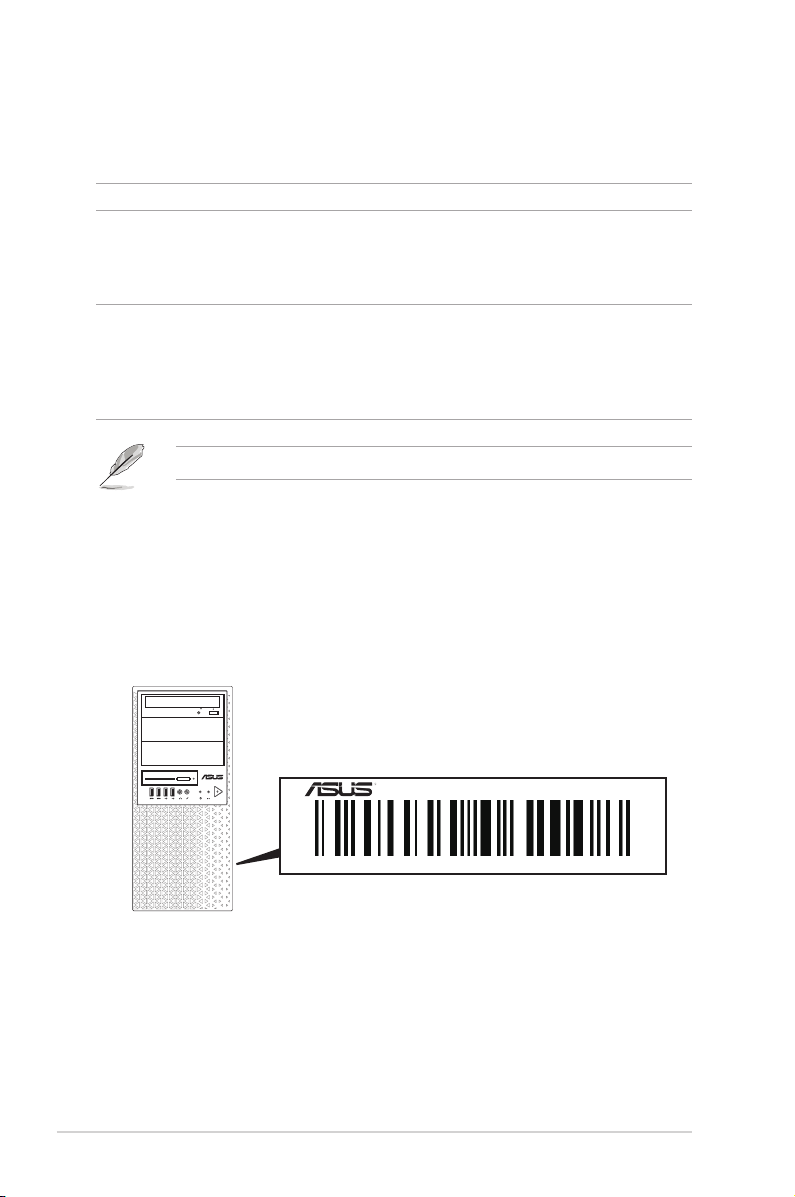
1.2 Serial number label
Before requesting support from the ASUS Technical Support team, you must take note of the
product’s serial number containing 12 characters such as xxS0xxxxxxxx shown as the gure
below. With the correct serial number of the product, ASUS Technical Support team members
can then offer a quicker and satisfying solution to your problems.
1-2
Smart Card
SD/MMC/MS
Pro E500 G6
xxS0xxxxxxxx
Chapter 1: Product Introduction
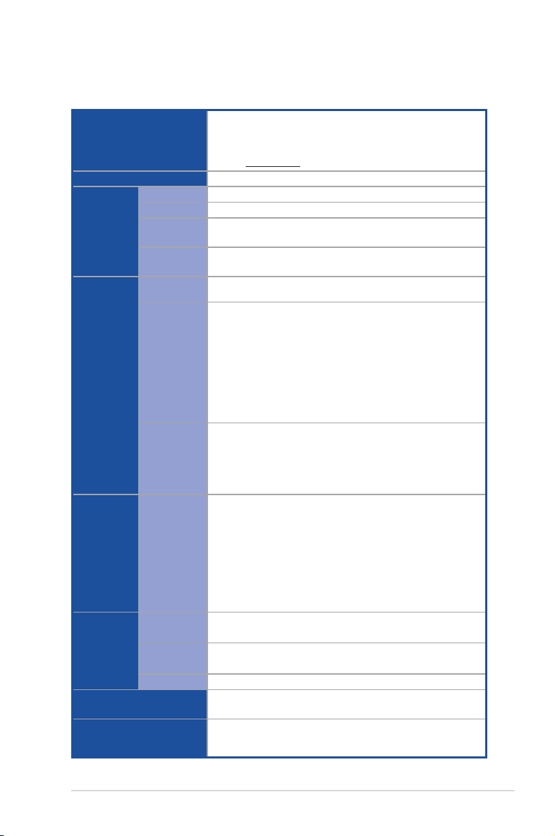
1.3 ProE500G6specicationssummary
The ASUS Pro E500 G6 is a workstation featuring the ASUS W480/SYS motherboard.
1 x Socket (LGA1200)
Processor / System Bus
Core Logic
Total Slots
Capacity
Memory
Memory Type
Memory Size
Total PCI/PCI-X
/PCI-E Slots
Slot Type
Expansion
Slots
M.2
Disk
Controller
Storage
Bays
SATA
Controller
Storage Bay
MB on-board
Connectors
Default Cable
Networking
VGA
Intel® Xeon® W-1200 Series Processors (up to 125W)
Intel® 10th Generation Core™ i9/i7/i5/i3 processors
Refer to www.asus.com for Intel® CPU support list.
*
Intel® W480 Chipset
4 (2-channel per CPU, 4 DIMM per CPU)
Maximum up to 128GB (UDIMM)
DDR4 2933/2666 MHz, ECC/Non-ECC UDIMM
* Refer to ASUS server AVL for the latest update.
32GB, 16GB, 8GB, 4GB (UDIMM)
* Refer to ASUS server AVL for the latest update.
6
Location-1: PCIe x1 slots (Gen3 x1 link, FH, FL)*
Location-2: PCIe x16 slots (Gen3 x16/x8 link, FH, FL)
Location-3: PCIe x1 slots (Gen3 x1 link, FH, FL)*
Location-4: PCIe x16 slots (Gen3 x0/x8 link, FH, FL)
Location-6: PCIe x16 slots (Gen3 x4 link, FH, FL)
Location-7: PCIe x16 slots (Gen3 x4 link, FH, FL)**
* The bandwidth of PCIe link is shared with M.2_1.
** The bandwidth of PCIe link is shared with 4 x SATA ports.
1 x M.2_1 socket3, up to 2280 type (SATA mode & PCIe
Gen3 x4 link)*
1 x M.2_2 socket3, up to 22110 type (PCIe Gen3 x4 link)**
* PCIe Bandwidth is shared between M.2 socket and PCIeX1.
** SATA Bandwidth is shared between M.2 socket and SATA port.
Intel® W480 Chipset:
8 x SATA 6Gb/s with 1 x M.2 (PCI-E Gen3 x2 link, NGFF 2280 /
2260 / 2242) or
7 x SATA 6Gb/s with 1 x M.2 (SATA 6Gb/s)
- 4 x SATA shared with PCIEX16_4
Intel® RST (Windows®)
(Support software RAID 0, 1, 10 & 5)
(Support Intel® Optane memory)
3 x Internal 3.5” Storage bays
1 x Internal 2.5” Storage bays
2 x M.2 connectors
8 x SATA 7-pin connector
4 x SATA 6G cables
1 x Intel® I225-LM 2.5GbE LAN
1 x Intel® I219-LM Gigabit LAN
CPU Integrated (Intel® UHD)
Multi-VGA output support: DVI-D/HDMI/DisplayPort/VGA
- Supports DVI-D with max. resolution 1920 x 1200@60 Hz
(continued on the next page)
ASUS Pro E500 G6
1-3

ProE500G6specicationssummary
- Supports HDMI 1.4 with max. resolution 4096 x 2160@24 Hz
VGA
Graphic
Audio
Auxiliary Storage Device
Bay (Floppy / Optical Drive)
Front I/O
Rear I/O
Switch/LED
Security Options
OS Support
Management Software
Dimension (HH x WW x DD)
Net Weight Kg (CPU, DRAM
& HDD not included)
Gross Weight Kg (CPU,
DRAM & HDD not included,
Packing included)
Power Supply and Rating
Environment
- Supports DisplayPort 1.2 with max. resolution 4096 x
2304@60 Hz
- Supports VGA with max. resolution 1920 x 1200@60 Hz
Up to 1 GPU Card
Realtek® ALC887 7.1-Channel High Denition Audio CODEC
2 x 5.25” media bays
(No ODD/DVD-RW)
2 x USB 3.2 Gen 1 ports
2 x USB 2.0 ports
1 x Headphone port
1 x Microphone port
2 x USB 3.2 Gen 2 ports (1 port at Type A, 1 port at USB Type-C®)
4 x USB 3.2 Gen 1 ports
1 x HDMI port
1 x DisplayPort
1 x DVI-D port
1 x VGA port
2 x LAN ports (RJ-45)
1 x 7.1-channel Audio I/O ports (5+1 Audio jacks)
Front Switch/LED:
1 x Power switch/LED
1 x Reset switch
1 x HDD Access LED
Trusted Platform Module (TPM 2.0)
Windows® 10 Pro for Workstation
* Refer to www.asus.com for the latest OS support.
ASUS Control Center
423 mm x 190 mm x 435 mm
16.7" x 7.48" x 17.1"
9.9 Kg
12.1 Kg
300W Bronze ATX Power Supply
(100-127/220-240Vac, 6/3A, 60-50Hz, Class I)
500W Gold ATX Power Supply
(100-240Vac, 50/60Hz, 7-3.5A)
700W Gold ATX Power Supply
(100-240Vac, 10-5A, 50/60Hz)
Operating temperature: 10°C ~ 35°C
Non operating temperature: -40°C ~ 70°C
Non operating humidity: 20% ~ 90% (Non condensing)
1-4
Specications are subject to change without notice.
Chapter 1: Product Introduction
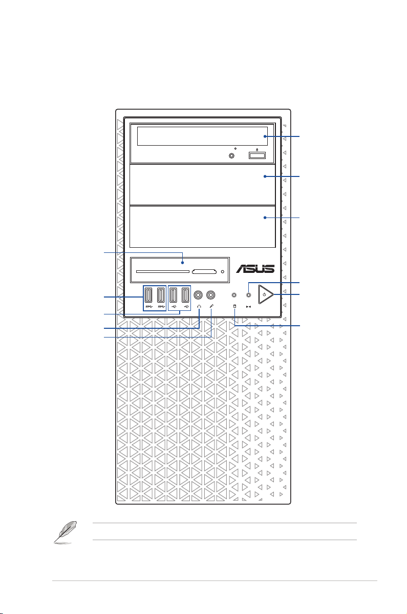
1.4 Front panel features
The Pro E500 G6 workstation features a simple yet stylish front panel design. The power and
reset buttons, LED indicators, optical drive, and USB ports are all conveniently located at the
front panel for easy access.
Optical Drive (Optional)
Empty 5.25-inch bay
Empty 5.25-inch bay
Card reader
Smart Card
USB 3.2 Gen 1 ports
USB 2.0 ports*
Headphone port
Microphone port
SD/MMC/MS
Reset button
Power button
HDD access LED
Refer to the Front panel LEDs section for the LED descriptions.
ASUS Pro E500 G6
1-5
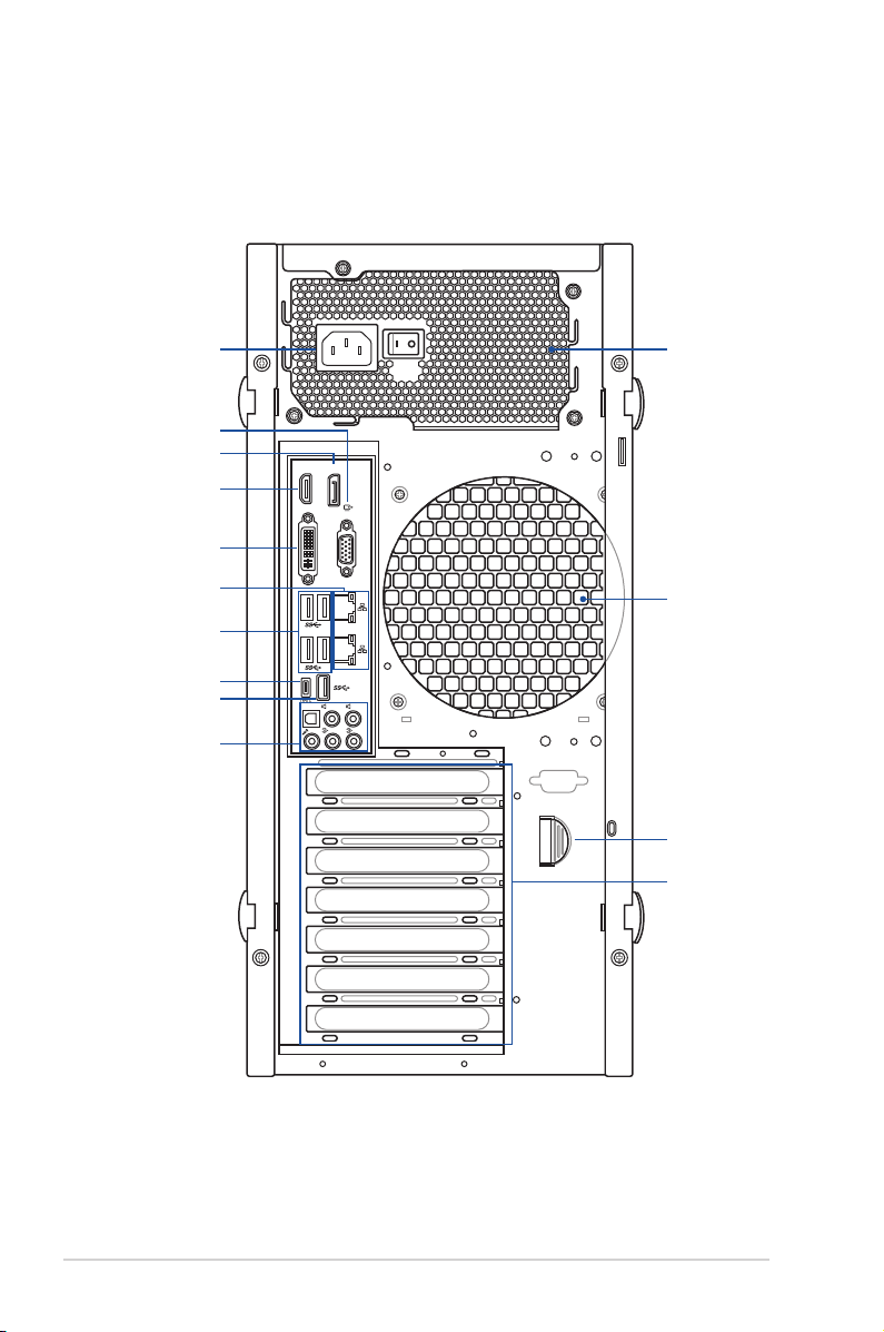
1.5 Rear panel features
The rear panel includes a slot for the motherboard rear I/O ports, expansion slots, a vent for
the system fan, and the power supply module.
Power connector
VGA port
DisplayPort
HDMI port
DVI port
LAN port
USB 3.2 Gen 1 ports
USB 3.2 Gen 2
Type-C® port
USB 3.2 Gen 2
Type-A port
Audio ports
HDMI
DVI
TYPE C
SPDIF OUT
MIC IN
Display/Port
VGA OUT
REAR C/SUB
LINE OUT
Single power supply
2.5G
10
LINE IN
KY
120 mm x 120 mm
system fan vents
PCIe latch
Expansion slots
1-6
Chapter 1: Product Introduction
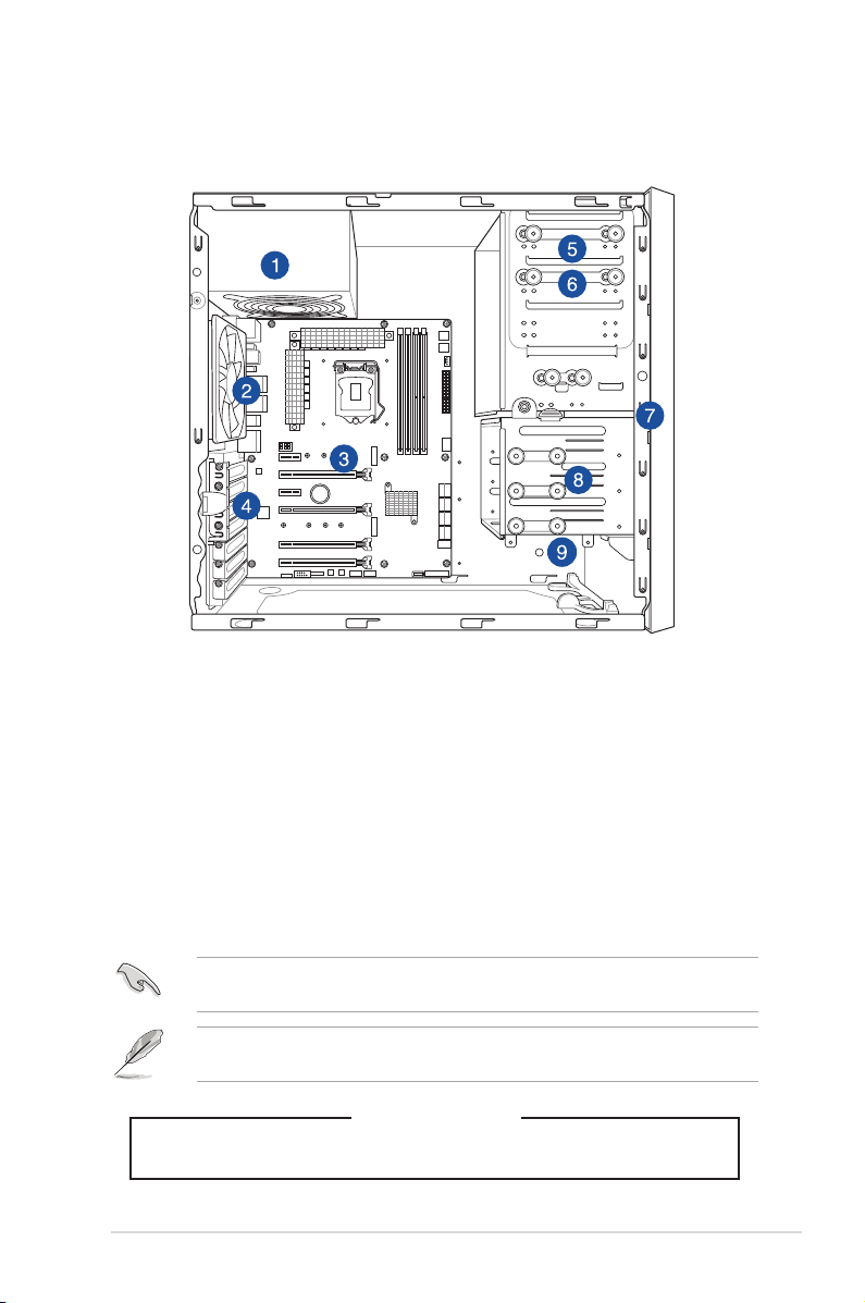
1.6 Internal features
The ASUS Pro E500 G6 Pedestal server system includes the basic components as shown:
1. Power supply unit
2. 120 mm x 120 mm system fan
3. ASUS W480/SYS motherboard
4. Expansion card locks
5. Optical drive (Optional)
6. 1 x 5.25-inch drive bay
7. Front I/O board (hidden)
8. 3 x 3.5-inch Internal storage bays
9. 1 x 2.5-inch Internal storage bay
Turn off the system power and detach the power supply before removing or replacing any
system component.
The barebone server does not include a floppy disk drive. If you need to use a floppy disk,
connect the USB floppy disk drive to any of the USB ports on the front or rear panel.
ASUS Pro E500 G6
HAZARDOUS MOVING PARTS
WARNING
KEEP FINGERS AND OTHER BODY PARTS AWAY
1-7
SD/MMC/MS
Smart Card
SD/MMC/MS
Smart Card
1.7 LED information
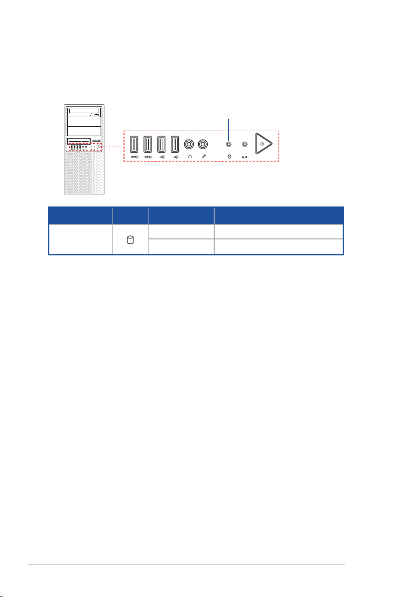
1.7.1 Front panel LEDs
HDD Access LED
LED Icon Display status Description
HDD Access LED
OFF
Blinking
No activity
Read/write data into the HDD
1-8
Chapter 1: Product Introduction
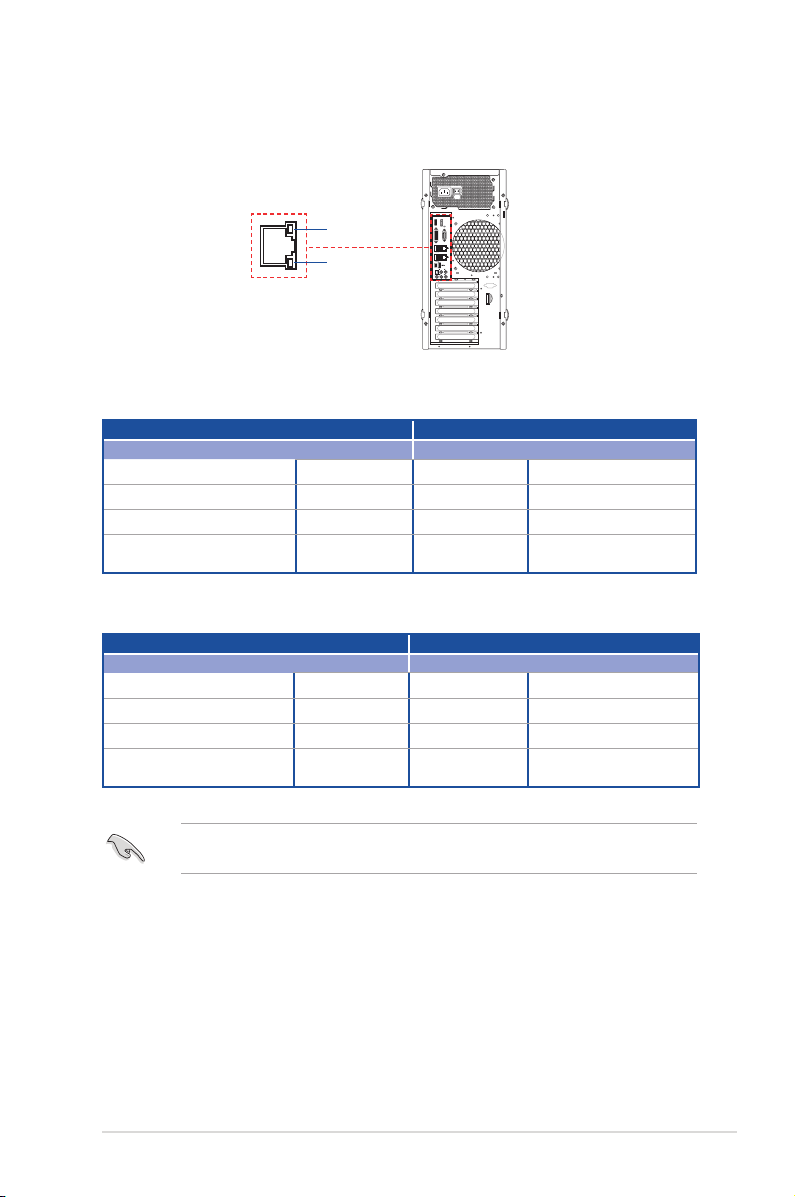
1.7.2 Rear panel LEDs
VGA
OUT
SPDIF OUT
USB 3.1
10
HDMI
Display/Port
DVI
ACT/LINK LED
SPEED LED
Intel® I219-LM 1G LAN ports LED indications
Activity Link LED Speed LED
Status Description Status Description
Off
Orange
Orange (Blinking)
Orange (Blinking then steady)
No link Off 10 Mbps connection
Linked Orange 100 Mbps connection
Data activity Green 1 Gbps connection
Ready to wake
up from S5 mode
Intel® I225-LM 2.5G LAN ports LED indications
Activity Link LED Speed LED
Status Description Status Description
Off
Green
Green (Blinking)
Green (Blinking then steady)
No link Off 10/100 Mbps connection
Linked Orange 1 Gbps connection
Data activity Green 2.5 Gbps connection
Ready to wake
up from S5 mode
VGA OUT
2.5G
10
TYPE C
REAR C/SUB
SPDIF OUT
LINE OUT
LINE IN
MIC IN
KY
ASUS Pro E500 G6
You can disable the LAN controllers in BIOS. Due to hardware design, the LAN1 port’s
LEDs may continue to blink even when disabled.
1-9

1-10
Chapter 1: Product Introduction

Chapter 2: Hardware Setup
Hardware Setup
This chapter lists the hardware setup procedures that you have
to perform when installing system components. It includes
description of the jumpers and connectors on the motherboard.
2
2.1 Chassis cover
MIC IN
REAR C/SUB
LINE OUT
LINE IN
KY
DVI
VGA OUT
HDMI
Display/Port
TYPE C
10
SPDIF OUT
2.5G
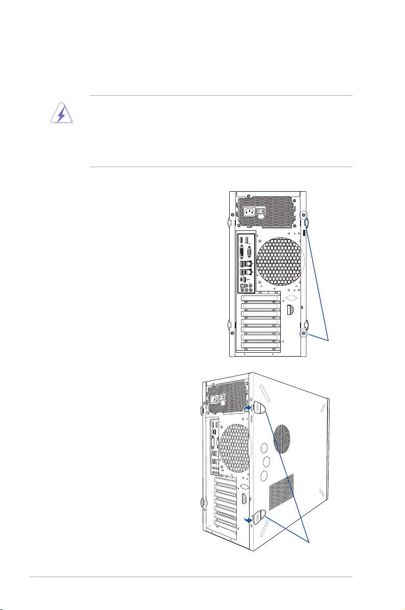
2.1.1 Removing the side cover
• Ensure that you unplug the power cord before removing the side cover.
• Takeextracarewhenremovingthesidecover.Keepyourngersfromcomponents
inside the chassis that can cause injury, such as the CPU fan, rear fan, and other
sharp-edged parts.
• The images of the system shown in this section are for reference purposes only and
may not exactly match the model you purchase.
To remove the side cover:
1. Remove the two screws that secure the
side cover.
HDMI
Display/Port
DVI
VGA OUT
2.5G
10
TYPE C
REAR C/SUB
SPDIF OUT
LINE OUT
LINE IN
MIC IN
KY
Screws
2. Press the side cover locks outward.
2-2
Side cover locks
Chapter 2: Hardware Setup
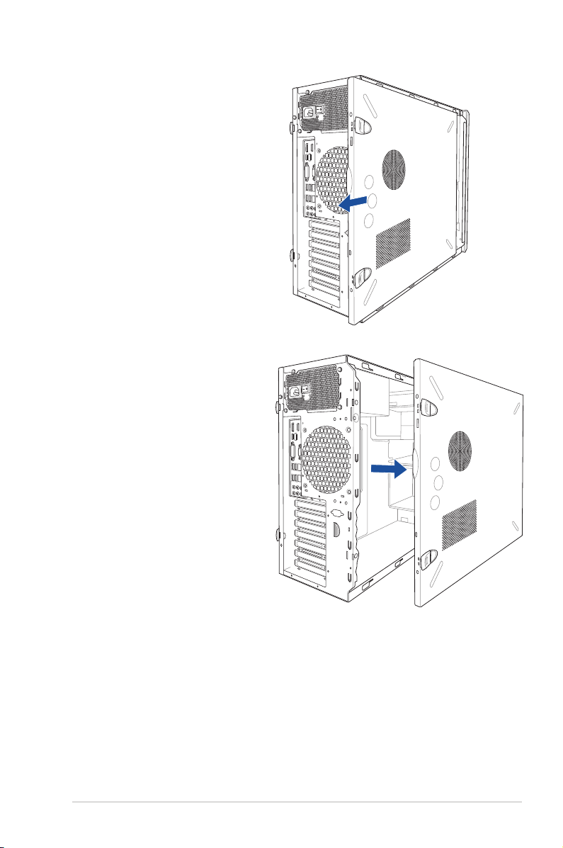
3. Slightly pull the side cover toward the
MIC IN
REAR C/SUB
LINE OUT
LINE IN
KY
DVI
VGA OUT
HDMI
Display/Port
TYPE C
10
SPDIF OUT
2.5G
rear just enough to detach it from the
chassis.
4. Remove the cover and set it aside.
ASUS Pro E500 G6
2-3
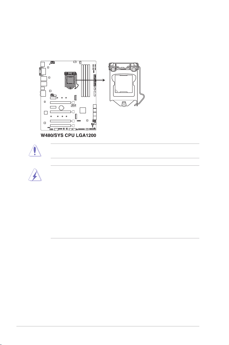
2.2 CPU installation
The motherboard comes with a surface mount LGA1200 socket for Intel
Series processors and Intel
Ensure that you install the correct CPU designed for LGA1200 socket only. DO NOT install
a CPU designed for other sockets on the LGA1200 socket.
• Ensure that all power cables are unplugged before installing the CPU.
• Upon purchase of the motherboard, ensure that the PnP cap is on the socket and
the socket contacts are not bent. Contact your retailer immediately if the PnP cap
is missing, or if you see any damage to the PnP cap/socket contacts/motherboard
components. ASUS will shoulder the cost of repair only if the damage is shipment/
transit-related.
• Keep the cap after installing the motherboard. ASUS will process Return Merchandise
Authorization (RMA) requests only if the motherboard comes with the cap on the
LGA1200 socket.
• The product warranty does not cover damage to the socket contacts resulting from
incorrect CPU installation/removal, or misplacement/loss/incorrect removal of the PnP
cap.
®
10th Generation Core™ i9/i7/i5/i3 processors.
®
Xeon® W-1200
2-4
Chapter 2: Hardware Setup
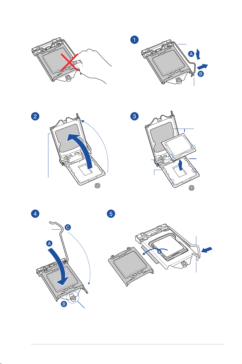
Gold
triangle
mark
Load lever
Retention tab
CPU notches
Alignment
key
Load plate
Load lever
ASUS Pro E500 G6
Retention
lock
Alignment
key
Load lever
Retention tab
2-5
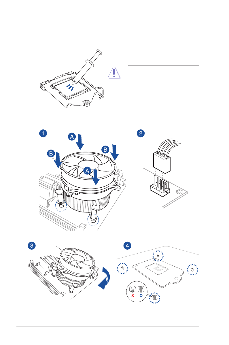
2.3 Cooling system installation
Apply the Thermal Interface Material to the
CPU heatsink and CPU before you install
the heatsink and fan, if necessary.
To install the CPU heatsink and fan assembly
2-6
Chapter 2: Hardware Setup
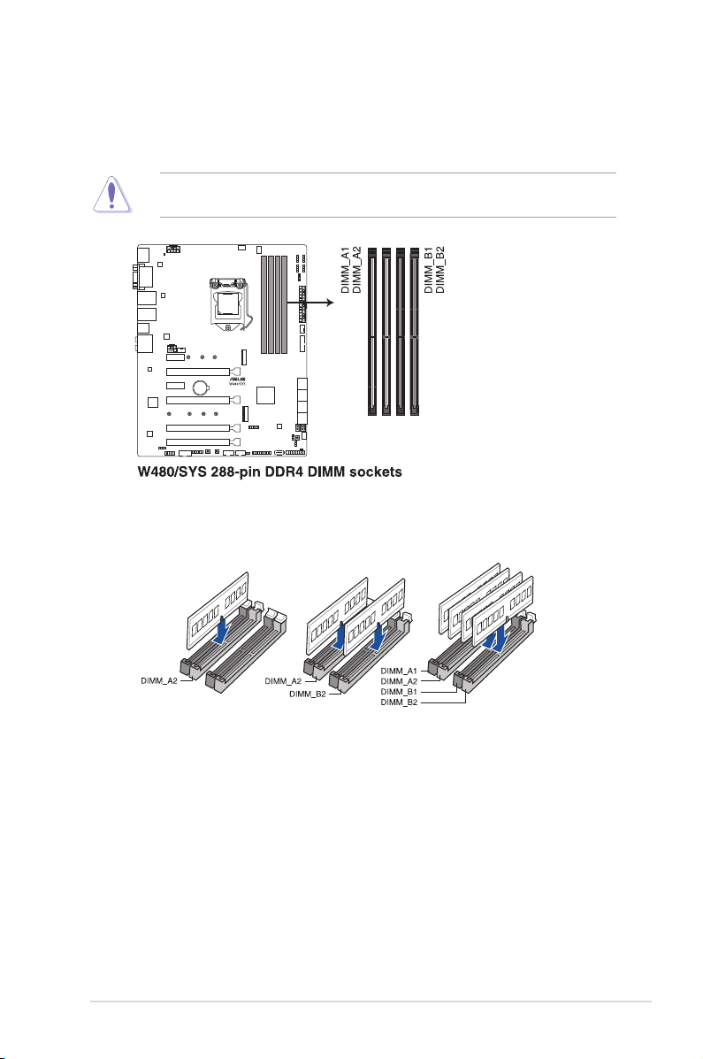
2.4 System memory
The motherboard comes with four DDR 4 (Double Data Rate 4) Dual Inline Memory Modules
(DIMM) slots.
A DDR4 module is notched differently from a DDR, DDR2 or DDR3 module. DO NOT install
a DDR, DDR2 or DDR3 memory module to the DDR4 slot.
Recommended memory congurations
ASUS Pro E500 G6
2-7

Memory congurations
You may install 4 GB, 8 GB 16 GB, and 32 GB unbuffered DDR4 DIMMs into the DIMM
sockets.
You may install varying memory sizes in Channel A and Channel B. The system maps the
totalsizeofthelower-sizedchannelforthedual-channelconguration.Anyexcessmemory
from the higher-sized channel is then mapped for single-channel operation.
• The default memory operation frequency is dependent on its Serial Presence Detect
(SPD), which is the standard way of accessing information from a memory module.
Under the default state, some memory modules for overclocking may operate at a
lower frequency than the vendor-marked value.
• Forsystemstability,useamoreefcientmemorycoolingsystemtosupportafull
memory load (4 DIMMs) or overclocking condition.
• Always install the DIMMS with the same CAS Latency. For an optimum compatibility,
we recommend that you install memory modules of the same version or data code
(D/C) from the same vendor. Check with the vendor to get the correct memory
modules.
• Visit the ASUS website for the latest QVL.
2-8
Chapter 2: Hardware Setup
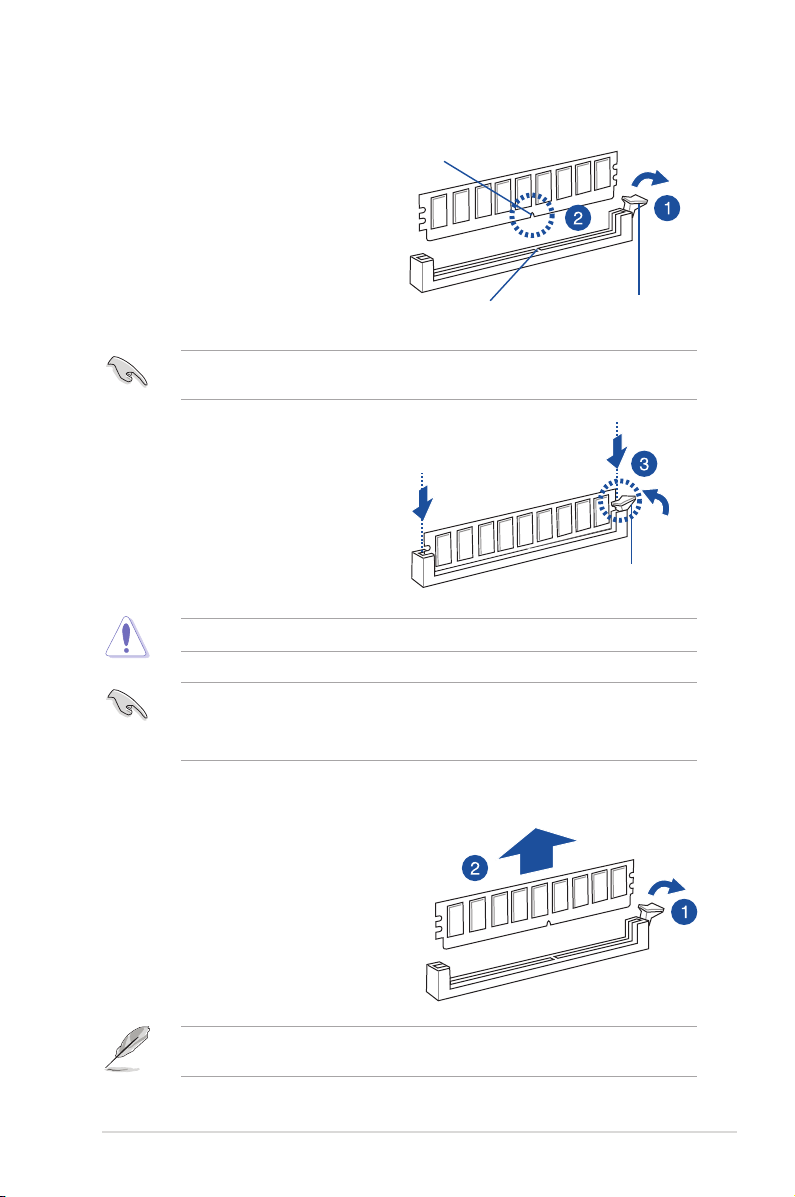
2.4.1 Installing a DIMM on a single clip DIMM socket
1. Unlock a DIMM socket by pressing the
retaining clip outward.
2. Align a DIMM on the socket such that
the notch on the DIMM matches the
DIMM slot key on the socket.
ADIMMiskeyedwithanotchsothatittsinonlyonedirection.DONOTforceaDIMMinto
a socket in the wrong direction to avoid damaging the DIMM.
3. Hold the DIMM by both of its ends
then insert the DIMM vertically into the
socket. Apply force to both ends of the
DIMM simultaneously until the retaining
clip snaps back into place and the
DIMM cannot be pushed in any further
to ensure proper sitting of the DIMM.
Always insert the DIMM into the socket vertically to prevent DIMM notch damage.
• To install two or more DIMMs, refer to the user guide bundled in the motherboard
package.
• RefertotheASUSwebsiteforqualiedvendorlistsofthememorymodules.
DIMM notch
DIMM slot key
Unlocked retaining clip
Locked Retaining Clip
Removing a DIMM from a single clip DIMM socket
1. Press the retaining clip outward to
unlock the DIMM.
2. Remove the DIMM from the socket.
SupporttheDIMMlightlywithyourngerswhenpressingtheretainingclips.TheDIMM
might get damaged when it flips out with extra force.
ASUS Pro E500 G6
2-9
2.5 Front panel cover
Beforeyoucaninstalla5.25-inchdrive,youshouldrstremovethefrontpanelcover.
Ensure to unplug the power cable before installing or removing any system components.
Failure to do so may cause damage to the motherboard and other system components!
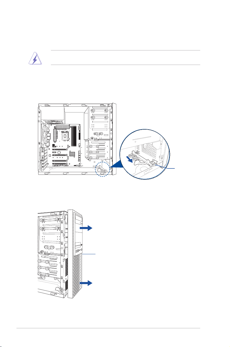
2.5.1 Removing the front panel cover
To remove the front panel cover:
1. Locate the front panel assembly lock then slide it outward to unlock the latches that
secure the front panel cover to the chassis.
Assembly lock
2. Remove the front panel assembly from the chassis and set it aside.
2-10
Front panel assembly
Chapter 2: Hardware Setup
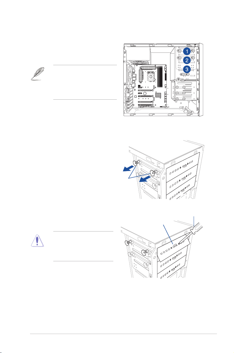
2.6 5.25-inch drives
This system comes with three 5.25-inch drive
bays located on the upper front section of the
chassis.
If your system came with an optical
drive, the optical drive occupies the
topmost bay (1). The lower bays (2
and 3) are available for additional
5.25-inch optical, zip, or floppy disk
drives.
Installing a 5.25-inch drive
To install a 5.25-inch drive:
1. Remove the front panel cover. Refer to
the Removing the front panel cover
section for more information.
2. Pull the bay locks outward.
Bay locks
3. Remove the metal cover of the bay
you intend to use.
Take extra care when removing the
metal cover. Use tools such as a
screw driver to bend and remove
the metal cover to avoid physical
injury.
ASUS Pro E500 G6
Screw driver
Metal cover
2-11
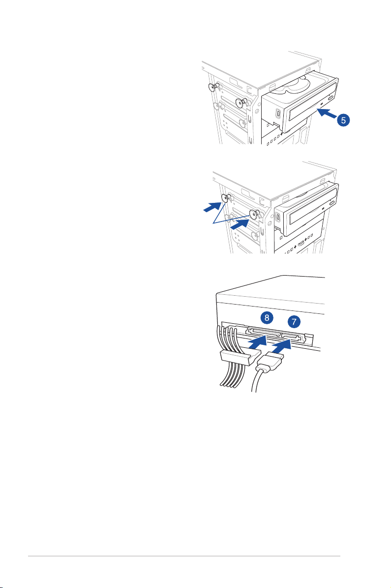
4. Prepare the 5.25-inch drive.
5. Insert and carefully push the drive into
the bay until its screw holes align with
the holes on the bay.
6. Push the bay locks to secure the drive in
place.
Bay locks
7. Connect the SATA cable to the SATA
connector of the drive.
8. Connect a SATA power cable from the
power supply to the power connector of
the drive.
9. Reinstall the front panel cover.
2-12
SATA cableSATA power cable
Chapter 2: Hardware Setup

2.7 Hard disk drives (HDD)
The server system supports three (3) 3.5-inch Serial ATA hard disk drives via the hard disk
drive bays and one 2.5-inch HDD/SSD drive at the bottom of the HDD cage.
Installing 3.5-inch HDDs
To install 3.5-inch Serial ATA hard disk drives:
1. Remove the side cover of the chassis. Refer to the Removing the side cover section
for more information.
2. Prepare the 3.5-inch HDD and the bundled set of screws.
3. Locate the HDD cage lock, press it up (A), then swing the HDD cage outwards (B) until
it clicks in place.
HDD cage lock
HDD cage
4. Align and insert the 3.5-inch HDD into
the drive bay ensuring that the screw
holes on the HDD matches the screw
holes on the HDD cage.
ASUS Pro E500 G6
Screw hole (HDD cage)
Screw holes (HDD)
2-13

5. Secure the 3.5-inch HDD to the HDD
cage using the bundled set of screws.
6. Swing the HDD cage inwards until it
clicks back into place.
7. Connect the SATA cable and SATA
power cable to the 3.5-inch HDD.
2-14
Chapter 2: Hardware Setup

Installing 2.5-inch HDD/SSD
To install a 2.5-inch HDD/SSD:
1. Remove the side cover of the chassis. Refer to the Removing the side cover section
for more information.
2. Prepare the 2.5-inch HDD/SDD and the bundled set of screws.
3. Lay the system on its side on a flat and stable surface.
4. Locate the HDD cage lock, press it up (A), then swing the HDD cage outwards (B).
5. Align and insert the 2.5-inch HDD/SSD into the drive bay as shown. Push it all the way
until its screw holes align with the holes on the drive bay.
HDD cage lock
2.5-inch HDD/SSD
HDD cage
ASUS Pro E500 G6
Matching screw holes
2-15

6. Secure the 2.5-inch HDD/SSD to
the HDD cage using the bundled
set of screws.
7. Swing the HDD cage inwards
until it clicks back into place.
8. Connect a SATA cable and a
SATA power cable to the 2.5-inch
HDD/SSD.
2-16
Chapter 2: Hardware Setup

2.8 Expansion slots
Unplug the power cord before adding or removing expansion cards. Failure to do so may
cause you physical injury and damage motherboard components.
Slot No. Slot Description
1 PCIE x1_1 slot
2 PCIE x16_1 slot
3 PCIE x1_2 slot
4 PCIE x16_2 slot
5 PCIE x16_3 slot
6 PCIE x16_4 slot
ASUS Pro E500 G6
2-17

2.8.1 Installing an expansion card
To install an expansion card:
1. Lay the system on its side on a flat, stable surface.
2. Press the PCIe latch (A), hold
it by its edge then lift it towards
the rear (B).
PCIe latch
3. Remove the screw (A) that
secures the metal bracket to
the chassis then remove the
metal bracket (B).
Screw
Metal bracket
Edge of the PCIe latch
2-18
Chapter 2: Hardware Setup

4. Align and insert the expansion card into
PCIe slotExpansion card
the PCIe slot.
5. Lift the PCIe latch inwards until it clicks into place securing the expansion card to the
chassis.
6. (Optional) Replace the screw of the
metal bracket.
ASUS Pro E500 G6
PCIe latch
2-19

2.8.2 Conguring an expansion card
VGA conguration
Single VGA/PCIe card
Dual VGA/PCIe cards
Triple VGA/PCIe cards
• In single VGA card mode, use the PCIe 3.0 x16_1 slot (gray) for a PCI Express x16
graphics card to get better performance.
• WerecommendthatyouprovidesufcientpowerwhenrunningCrossFireX™mode.
• We recommend you connect the EATX12V_1 cable when running CrossFireX™.
• Connect a chassis fan to the motherboard connector labeled CHA_FAN1/2 when
using multiple graphics cards for better thermal environment.
PCI Express operating mode
PCIe 3.0 x16_1 (gray) PCIe 3.0 x16_2 PCIe 3.0 x16_3
x16 (Recommended for
single VGA card)
x8 x8 N/A
x8 x8 x4
N/A N/A
2-20
Chapter 2: Hardware Setup

2.8.3 Installing M.2 (NGFF) cards
To install an M.2 card:
1. Locate the M.2 connector (M.2(SOCKET3)) on the motherboard.
2. Remove the screw on the stand screw.
3. Prepare the M.2 card.
4. Align and insert the M.2 card into the
M.2 connector (M.2(SOCKET3)).
5. Secure the M.2 card with the screw you
removed in step 2.
• Please pay attention when removing the screw, the stand screw might be removed
together with it.
• Ensure that the M.2 card is positioned between the screw and the stand screw before
securing it.
NGFF1
Stand screw
Screw
Screw hole
ASUS Pro E500 G6
2-21

2.9 System fan
This section describes how to remove the system fan in the event that you need to install or
remove previously installed or new system components, or when the system fan needs to be
replaced because it was damaged or became defective.
To remove the system fan:
1. Disconnect the system fan cable from
the CHA_FAN1 connector on the
motherboard.
2. Remove the four system fan screws at
the rear panel. Keep the screws for later
use.
Hold the system fan with one hand
while removing the system fan
screws.
3. Remove the system fan.
Follow the previous instructions in
reverse order if you want to reinstall
the system fan.
2-22
Chapter 2: Hardware Setup

2.10 BIOS update utility
USB BIOS FlashBack™
USB BIOS FlashBack™ allows you to easily update the BIOS without entering a bootable
environment, ideal for BIOS recovery, rollback, or updates to support new CPUs. Simply
insert a USB storage device to the USB port (the USB port is marked the I/O shield) then
press the USB BIOS FlashBack™ button for three seconds to start the update process.
To use USB BIOS FlashBack™:
1. Download the latest BIOS from the support site at www.asus.com/support/ and save it
to a USB storage device.
• We recommend you to use a USB 2.0 storage device to save the latest BIOS version
for better compatibility and stability.
• WhendownloadingorupdatingtheBIOSle,renameitasW480S.CAP for this
motherboard.
2. Insert the USB storage device to the
USB FlashBack™ port.
3. Shut down your computer.
4. On your motherboard, press the
BIOS FlashBack™ button for three
seconds until the FlashBack™ LED
blinks three times, indicating that
the BIOS FlashBack™ function is
enabled.
ASUS Pro E500 G6
2-23

Refer to section Onboard LEDs for more information of the FlashBack™ LED.
5. Wait until the light goes out, indicating that the BIOS updating process is completed.
For more BIOS update utilities in BIOS setup, refer to the section Updating BIOS in
Chapter 4.
• Do not unplug portable disk, power system, or short the CLRTC header while BIOS
update is ongoing, otherwise update will be interrupted. In case of interruption, please
press and hold the BIOS_FLBK button for 3 seconds again to restart the process.
• Ifthelightashesforvesecondsandturnsintoasolidlight,thismeansthatthe
BIOS FlashBack™ is not operating properly. Please check the following when this
happens:
- The USB drive should only contain a single partition.
- TheUSBdriveshouldbeformattedtoaFAT32,FAT16,orNTFSlesystem.
- TheBIOSlenameshouldbecorrectlynamed,andintherootfolderoftheUSB
drive.
- If the problem persists, the USB drive may not be compatible, please try another
USB drive of a different brand/model.
Then retry the flashback by pressing the BIOS FlashBack™ button for three seconds
until the FlashBack™ LED starts to blink.
2-24
Chapter 2: Hardware Setup

2.11 Motherboard rear and audio connection
2.11.1 Rear I/O connection
Rear panel connectors
1. DisplayPort 7. DVI-D port
2. VGA port 8. USB 3.2 Gen 1 ports 5 and 6
3. Intel® LAN I225 9. USB 3.2 Gen 1 ports 3 and 4
4. Intel® LAN I219 10. USB 3.2 Gen 2 Type-C® port EC1
5. USB 3.2 Gen 2 Type-A port E1 11. Optical S/PDIF Out port
6. HDMI 1.4b port 12. Audio I/O ports*
* : Refer to the tables below for audio port denitions.
* Audio 2, 4, 5.1 or 7.1-channel conguration
Port
Light Blue Line In Line In Line In Side Speaker Out
Lime Line Out Front Speaker Out Front Speaker Out Front Speaker Out
Pink Mic In Mic In Mic In Mic In
Orange – – Center/Sub woofer Center/Sub woofer
Black – Rear Speaker Out Rear Speaker Out Rear Speaker Out
ASUS Pro E500 G6
Headset
2-channel
4-channel 5.1-channel 7.1-channel
2-25

2.11.2 Audio I/O connections
Audio I/O ports
Connect to Headphone and Mic
Connect to Stereo Speakers
Connect to 2-channel Speakers
2-26
Chapter 2: Hardware Setup

Connect to 4-channel Speakers
Connect to 5.1-channel Speakers
Connect to 7.1-channel Speakers
ASUS Pro E500 G6
2-27

2-28
Chapter 2: Hardware Setup

Chapter 3: Motherboard Information
Motherboard Information
This chapter includes the motherboard layout and brief
descriptions of the jumpers and internal connectors.
3

3.1 Motherboard layout
3-2
Chapter 3: Motherboard Information

Layout contents
Connectors/Jumpers/Buttons and switches/Slots Page
1. ATX power connectors (24-pin EATXPWR; 8-pin EATX12V; 6-pin
EATX12V_1)
2. LGA1200 CPU socket 2-4
3. Fan connectors (4-pin CPU_FAN; 4-pin CPU_OPT; 4-pin CHA_FAN1-3) 3-13
4. DDR4 DIMM slots 2-7
5. USB 3.2 Gen 1 connector (20-1 pin U32G1_12) 3-11
6. M.2 sockets (M.2_1; M.2_2) 3-16
7. Intel® Serial ATA 6 Gb/s connectors (7-pin SATA6G_1-8) 3-9
8. Q-Code LED 3-8
9. BIOS FlashBack™ button 2-23
10. LPT and Q-Code switch (3-pin LPT_P80_SW) 3-6
11. System panel connector (20-3 pin PANEL) 3-14
12. USB 2.0 connectors (10-1 pin USB1112, USB1314; 4-pin Type-A USB9) 3-12
13. Clear RTC RAM (2-pin CLRTC) 3-5
14. LPT connector (26-1 pin LPT) 3-17
15. Thermal Sensor connector (2-pin T_SENSOR) 3-17
16. Power-on button 3-4
17. Reset button 3-4
18. TPM connector (14-1 pin TPM) 3-10
19. Serial port connector (10-1 pin COM1) 3-12
20. Front panel audio connector (10-1 pin AAFP) 3-10
21. Digital audio connector (4-1 pin SPDIF_OUT) 3-13
3-15
ASUS Pro E500 G6
3-3

3.2 Onboard buttons and switches
Onboard buttons and switches allow you to ne-tune performance when working on a bare or
open-case system. This is ideal for overclockers and gamers who continually change settings
to enhance system performance.
1. Power-on button
The motherboard comes with a power-on button that allows you to power up or wake
up the system. The button also lights up when the system is plugged to a power source
indicating that you should shut down the system and unplug the power cable before
removing or installing any motherboard component.
2. Reset button
Press the reset button to reboot the system.
3-4
Chapter 3: Motherboard Information

3.3 Jumpers
1. Clear RTC RAM (2-pin CLRTC)
This header allows you to clear the Real Time Clock (RTC) RAM in CMOS. You can
clear the CMOS memory of date, and system setup parameters by erasing the CMOS
RTC RAM data. The onboard button cell battery powers the RAM data in CMOS, which
include system setup information such as system passwords.
To erase the RTC RAM:
1. Turn OFF the computer and unplug the power cord.
2. Use a metal object such as a screwdriver to short the two pins.
3. Plug the power cord and turn ON the computer.
4. Hold down the <Del> key during the boot process and enter BIOS setup to reenter data.
Except when clearing the RTC RAM, never short-circuit the CLRTC jumper. Shorting the
CLRTC jumper will cause system boot failure!
If the steps above do not help, remove the onboard battery and short the two pins again to
clear the CMOS RTC RAM data. After clearing the CMOS, reinstall the battery.
ASUS Pro E500 G6
3-5

2. LPT and Q-Code switch (3-pin LPT_P80_SW)
This header allows you to enable either LPT (Line Printing Thermal) connector or
Q-Code at a time.
To switch between LPT and Q-Code:
1. Turn OFF the computer and unplug the power cord.
2. Move the jumper cap to switch between LPT and Q-Code.
3. Plug the power cord and turn ON the computer.
3-6
Chapter 3: Motherboard Information

3.4 Onboard LEDs
1. Q LED (CPU, DRAM, VGA, BOOT)
Q LED checks key components (CPU, DRAM, VGA card, and booting devices) in
sequence during motherboard booting process. If an error is found, the corresponding
LED remains lit until the problem is solved. This user-friendly design provides an
intuitive way to locate the root problem within seconds.
The Q LEDs provide the most probable cause of an error code as a starting point for
troubleshooting. The actual cause may vary from case to case.
2. USB BIOS FlashBack™ LED (FLBK_LED)
The BIOS FlashBack™ LED flashes when you press the BIOS FlashBack™ button for
BIOS update.
ASUS Pro E500 G6
3-7

3. Q-Code LED
The Q-Code LED design provides you with a 2-digit error code that displays the system
status. Refer to the Q-Code table on the next page for details.
The Q-Code LED provides the most probable cause of an error code as a starting point for
troubleshooting. The actual cause may vary from case to case.
3-8
Chapter 3: Motherboard Information

3.5 Internal connectors
1. Intel® Serial ATA 6 Gb/s connectors (7-pin SATA6G_1-8)
These connectors connect to Serial ATA 6 Gb/s hard disk drives via Serial ATA 6 Gb/s
signal cables.
If you installed Serial ATA hard disk drives, you can create a RAID 0, 1, 5, and 10
conguration with the Intel® Rapid Storage Technology enterprise through the onboard
Intel® W480 chipset.
• These connectors are set to [AHCI Mode] by default. If you intend to create a Serial
ATA RAID set using these connectors, set the SATA Mode item in the BIOS to [Intel
RST Premium with Intel Optane System Acceleration(RAID)].
• SATA6G_2 port shares bandwidth with M.2_1 socket. When M.2_1 slot runs in SATA
mode, the SATA6G_2 port will be disabled.
ASUS Pro E500 G6
3-9

2. Front panel audio connector (10-1 pin AAFP)
This connector is for a chassis-mounted front panel audio I/O module that supports HD
Audio. Connect one end of the front panel audio I/O module cable to this connector.
We recommend that you connect a high-denition front panel audio module to this
connector to avail of the motherboard’s high-denition audio capability.
3. TPM connector (14-1 pin TPM)
This connector supports a Trusted Platform Module (TPM) system, which securely
store keys, digital certicates, passwords and data. A TPM system also helps enhance
network security, protect digital identities, and ensures platform integrity.
3-10
The TPM module is purchased separately.
Chapter 3: Motherboard Information

4. USB 3.2 Gen 1 connector (20-1 pin U32G1_12)
This connector allows you to connect a USB 3.2 Gen 1 module for additional USB
3.2 Gen 1 front or rear panel ports. With an installed USB 3.2 Gen 1 module, you can
enjoy all the benets of USB 3.2 Gen 1 including faster data transfer speeds of up to
5 Gb/s, faster charging time for USB-chargeable devices, optimized power efciency,
and backward compatibility with USB 2.0.
The USB 3.2 Gen 1 module is purchased separately.
The plugged USB 3.2 Gen 1 device may run on xHCI or EHCI mode depending on the
operating system’s setting.
ASUS Pro E500 G6
3-11

5. USB 2.0 connectors (10-1 pin USB1112, USB1314; 4-pin Type-A USB9)
The 10-1 pin connector allows you to connect a USB 2.0 module for additional USB
2.0 front or rear panel ports. The 4-pin USB (Universal Serial Bus) Type-A port is
available for connecting USB 2.0 devices. These USB connectors comply with USB 2.0
specication that supports up to 480 Mbps connection speed.
DO NOT connect a 1394 cable to the USB connectors. Doing so will damage the
motherboard!
6. Serial port connector (10-1 pin COM1)
This connector is for a serial (COM) port. Connect the serial port module cable to this
connector, then install the module to a slot opening at the back of the system chassis.
3-12
Chapter 3: Motherboard Information

7. Fan connectors (4-pin CPU_FAN; 4-pin CPU_OPT; 4-pin CHA_FAN1-3)
Connect the fan cables to the fan connectors on the motherboard, ensuring that the
black wire of each cable matches the ground pin of the connector.
• DO NOT forget to connect the fan cables to the fan connectors. Insufcient air flow
inside the system may damage the motherboard components. These are not jumpers!
Do not place jumper caps on the fan connectors!
• Ensure that the CPU fan cable is securely installed to the CPU fan connector.
8. Digital audio connector (4-1 pin SPDIF_OUT)
This connector is for an additional Sony/Philips Digital Interface (S/PDIF) port. Connect
the S/PDIF Out module cable to this connector, then install the module to a slot
opening at the back of the system chassis.
The S/PDIF module is purchased separately.
ASUS Pro E500 G6
3-13

9. System panel connector (20-3 pin PANEL)
This connector supports several chassis-mounted functions.
• System power LED (2-pin or 3-1 pin PLED)
The 2-pin or 3-1 pin connector is for the system power LED. Connect the chassis
power LED cable to this connector. The system power LED lights up when you turn on
the system power, and blinks when the system is in sleep mode.
• Hard disk drive activity LED (2-pin HDD_LED)
This 2-pin connector is for the HDD Activity LED. Connect the HDD Activity LED cable
to this connector. The HDD LED lights up or flashes when data is read from or written
to the HDD.
• System warning speaker (4-pin SPEAKER)
This 4-pin connector is for the chassis-mounted system warning speaker. The speaker
allows you to hear system beeps and warnings.
• ATX power button/soft-off button (2-pin PWRSW)
This connector is for the system power button. Pressing the power button turns the
system on or puts the system in sleep or soft-off mode depending on the operating
system settings. Pressing the power switch for more than four seconds while the
system is ON turns the system OFF.
• Reset button (2-pin RESET)
This 2-pin connector is for the chassis-mounted reset button for system reboot without
turning off the system power.
• Chassis intrusion connector (2-pin CHASSIS)
This connector is for a chassis-mounted intrusion detection sensor or switch. Connect
one end of the chassis intrusion sensor or switch cable to this connector. The chassis
intrusion sensor or switch sends a high-level signal to this connector when a chassis
component is removed or replaced. The signal is then generated as a chassis intrusion
event.
3-14
Chapter 3: Motherboard Information

10. ATX power connectors (24-pin EATXPWR; 8-pin EATX12V; 6-pin EATX12V_1)
These connectors are for ATX power supply plugs. The power supply plugs are
designed to t these connectors in only one orientation. Find the proper orientation and
push down rmly until the connectors completely t.
Ensure to connect the 8-pin power plug, or connect both the 8-pin and 6-pin power plugs.
• For a fully congured system, we recommend that you use a power supply unit
(PSU) that complies with ATX 12 V Specication 2.0 (or later version) and provides a
minimum power of 350 W.
• DO NOT forget to connect the 8-pin EATX12V power plug. Otherwise, the system will
not boot.
• We recommend that you use a PSU with a higher power output when conguring a
system with more power-consuming devices. The system may become unstable or
may not boot up if the power is inadequate.
• If you want to use two or more high-end PCI Express x16 cards, use a PSU with
1000W power or above to ensure the system stability, and recommend connecting the
6-pin EATX12V_1 power plug.
ASUS Pro E500 G6
3-15

11. M.2 sockets (M.2_1; M.2_2)
These sockets allow you to install M.2 SSD modules.
• M.2_1 socket supports PCIe 3.0 x4 and SATA mode M Key design and type 2242 /
2260 / 2280 PCIe and SATA storage devices.
• M.2_2 socket supports PCIe 3.0 x4 M Key design and type 2242 / 2260 / 2280 / 22110
PCIe storage devices.
• M.2_1 socket shares bandwidth with SATA6G_2 port. When M.2_1 slot runs in SATA
mode, the SATA6G_2 port will be disabled.
• These sockets support IRST (Intel® Rapid Storage Technology).
• These sockets support Intel® Optane memory.
3-16
The M.2 SSD module is purchased separately.
Chapter 3: Motherboard Information

12. LPT connector (26-1 pin LPT)
The LPT (Line Printing Terminal) connector supports devices such as a printer. LPT
standardizes as IEEE 1284, which is the parallel port interface on IBM PC-compatible
computers.
13. Thermal Sensor connector (2-pin T_SENSOR)
The Thermal Sensor connector allows you to connect a sensor to monitor the
temperature of the devices and the critical components inside the motherboard.
Connect the thermal sensor and place it on the device or the motherboard’s
component to detect its temperature.
The thermal sensor is purchased separately.
ASUS Pro E500 G6
3-17

3-18
Chapter 3: Motherboard Information

Chapter 4: BIOS Setup
BIOS Setup
This chapter tells how to change the system settings through
the BIOS Setup menus. Detailed descriptions of the BIOS
parameters are also provided.
4

4.1 Knowing BIOS
The new ASUS UEFI BIOS is a Unied Extensible Interface that complies with UEFI
architecture, offering a user-friendly interface that goes beyond the traditional keyboardonly BIOS controls to enable a more exible and convenient mouse input. You can easily
navigate the new UEFI BIOS with the same smoothness as your operating system. The
term “BIOS” in this user manual refers to “UEFI BIOS” unless otherwise specied.
BIOS (Basic Input and Output System) stores system hardware settings such as storage
device conguration, overclocking settings, advanced power management, and boot
device conguration that are needed for system startup in the motherboard CMOS. In
normal circumstances, the default BIOS settings apply to most conditions to ensure
optimal performance. DO NOT change the default BIOS settings except in the following
circumstances:
• An error message appears on the screen during the system bootup and requests you
to run the BIOS Setup.
• You have installed a new system component that requires further BIOS settings or
update.
Inappropriate BIOS settings may result to instability or boot failure. We strongly
recommend that you change the BIOS settings only with the help of a trained service
personnel.
When downloading or updating the BIOS le for your motherboard, rename it as
•
W480S.CAP. The name of the CAP le varies depending on models. Refer to the user
manual that came with your motherboard for the name.
• The screenshots in this manual are for reference only, please refer to the latest BIOS
version for settings and options.
• BIOS settings and options may vary due to different BIOS release versions. Please
refer to the latest BIOS version for settings and options.
4-2
Chapter 4: BIOS Setup

4.2 BIOS setup program
Use the BIOS Setup to update the BIOS or congure its parameters. The BIOS screen
include navigation keys and brief onscreen help to guide you in using the BIOS Setup
program.
Entering BIOS at startup
To enter BIOS Setup at startup, press <Delete> or <F2> during the Power-On Self Test
(POST). If you do not press <Delete> or <F2>, POST continues with its routines.
Entering BIOS Setup after POST
To enter BIOS Setup after POST:
• Press <Ctrl>+<Alt>+<Delete> simultaneously.
• Press the reset button on the system chassis.
• Press the power button to turn the system off then back on. Do this option only if you
failed to enter BIOS Setup using the rst two options.
After doing either of the three options, press <Delete> key to enter BIOS.
• The BIOS setup screens shown in this section are for reference purposes only, and
may not exactly match what you see on your screen.
• Ensure that a USB mouse is connected to your motherboard if you want to use the
mouse to control the BIOS setup program.
• If the system becomes unstable after changing any BIOS setting, load the default
settings to ensure system compatibility and stability. Select the Load Optimized
Defaults item under the Exit menu or press hotkey <F5>. See section Exit menu for
details.
• If the system fails to boot after changing any BIOS setting, try to clear the CMOS
and reset the motherboard to the default value. See your motherboard manual for
information on how to erase the RTC RAM.
• The BIOS setup program does not support Bluetooth devices.
BIOS menu screen
The BIOS Setup program can be used under two modes: EZ Mode and Advanced Mode.
You can change modes from Setup Mode in Boot menu or by pressing the <F7> hotkey.
The BIOS settings and options for each motherboard may differ slightly with the options in
this manual. Please refer to the BIOS of your motherboard for the settings and options.
ASUS Pro E500 G6
4-3

4.2.1 EZ Mode
The EZ Mode provides you an overview of the basic system information, and allows you to
select the display language, system performance, mode and boot device priority. To access
the Advanced Mode, select Advanced Mode or press the <F7> hotkey for the advanced
BIOS settings.
The default screen for entering the BIOS setup program can be changed. Refer to the
Setup Mode item in section Boot menu for details.
Displays the system properties of the selected mode.
Displays a quick overview of the
system status
Selects the display language
of the BIOS setup program
Searches by BIOS item name,
enter the item name to nd the
related item listing
Click < or > to switch EZ System Tuning modes
Enables or disables the SATA RAID mode
for Intel Rapid Storage Technology
Displays the CPU Fan’s speed. Click
the button to manually tune the fans
The boot device options vary depending on the devices you installed to the system.
4-4
Loads optimized
default settings
Selects the boot device priority
Saves the changes
and resets the system
Click to go to Advanced mode
Click to display boot devices
Chapter 4: BIOS Setup

4.2.2 Advanced Mode
The Advanced Mode provides advanced options for experienced end-users to congure
the BIOS settings. The gure below shows an example of the Advanced Mode. Refer to the
following sections for the detailed congurations.
To switch from EZ Mode to Advanced Mode, click Advanced Mode(F7) or press the <F7>
hotkey.
Conguration elds
Pop-up Menu
Menu bar
Language Qfan Control(F6)
Menu items
MyFavorite(F3)
General help
Search(F9)
Last modied settings
Scroll bar
Go back to EZ Mode
Displays a quick overview
of the system status
Hot Keys
ASUS Pro E500 G6
4-5

Menu bar
The menu bar on top of the screen has the following main items:
My Favorites
Main
Ai Tweaker
Advanced
Monitor
Boot
Tool
Exit
For saving the frequently-used system settings and conguration.
For changing the basic system conguration
For changing the overclocking settings
For changing the advanced system settings
For displaying the system temperature, power status, and changing
the fan settings.
For changing the system boot conguration
For conguring options for special functions
For selecting the exit options and loading default settings
Menu items
The highlighted item on the menu bar displays the specic items for that menu. For example,
selecting Main shows the Main menu items.
The other items (My Favorites, Ai Tweaker, Advanced, Monitor, Boot, Tool, and Exit) on the
menu bar have their respective menu items.
Submenu items
A greater than sign (>) before each item on any menu screen means that the item has a
submenu. To display the submenu, select the item and press <Enter>.
Language
This button above the menu bar contains the languages that you can select for your BIOS.
Click this button to select the language that you want to display in your BIOS screen.
MyFavorite (F3)
This button above the menu bar shows all BIOS items in a Tree Map setup. Select frequentlyused BIOS settings and save it to MyFavorites menu.
Refer to section My Favorites for more information.
QFan Control (F6)
This button above the menu bar displays the current settings of your fans. Use this button to
manually tweak the fans to your desired settings.
Refer to section QFan Control for more information.
4-6
Chapter 4: BIOS Setup

Search (F9)
This button allows you to search for BIOS items by entering its name, enter the item name to
nd the related item listing.
Hot keys
This button contains the navigation keys for the BIOS setup program. Use the navigation
keys to select items in the menu and change the settings.
Scroll bar
A scroll bar appears on the right side of a menu screen when there are items that do not t
on the screen. Press the Up/Down arrow keys or <Page Up> / <Page Down> keys to display
the other items on the screen.
General help
At the bottom of the menu screen is a brief description of the selected item. Use <F12> key
to capture the BIOS screen and save it to the removable storage device.
Conguration elds
These elds show the values for the menu items. If an item is user-congurable, you can
change the value of the eld opposite the item. You cannot select an item that is not usercongurable.
A congurable eld is highlighted when selected. To change the value of a eld, select it and
press <Enter> to display a list of options.
Last Modied button
This button shows the items that you last modied and saved in BIOS Setup.
ASUS Pro E500 G6
4-7

4.2.3 Q-Fan Control
The QFan Control allows you to set a fan prole or manually congure the operating speed of
your CPU and chassis fans.
Click to select a fan to be
congured
4-8
Select a prole to
apply to your fans
Click to apply the fan setting
Click to undo the
changes
Click to go back to main menu
Select to manually congure
your fans
Chapter 4: BIOS Setup

Conguring fans manually
Select Manual from the list of proles to manually congure your fans’ operating speed.
Speed points
Select to manually
congure your fans
To congure your fans:
1. Select the fan that you want to congure and to view its current status.
2. Click and drag the speed points to adjust the fans’ operating speed.
3. Click Apply to save the changes then click Exit (ESC).
ASUS Pro E500 G6
4-9

4.3 My Favorites
My Favorites is your personal space where you can easily save and access your favorite
BIOS items.
My Favorites comes with several performance, power saving, and fast boot related items by
default. You can personalize this screen by adding or removing items.
4-10
Chapter 4: BIOS Setup

Adding items to My Favorites
To add BIOS items:
1. Press <F3> on your keyboard or click from the BIOS screen to open
Setup Tree Map screen.
2. On the Setup Tree Map screen, select the BIOS items that you want to save in My
Favorites screen.
Main menu panel
Selected shortcut
items
Submenu panel
Delete all favorite
items
Recover to default
favorite items
3. Select an item from main menu panel, then click the submenu that you want to save as
favorite from the submenu panel and click or press <Enter> on your keyboard.
You cannot add the following items to My Favorite items:
• Items with submenu options
• User-managed items such as language and boot order
• Conguration items such as Memory SPD Information, system time and date.
4. Click Exit (ESC) or press <Esc> key to close Setup Tree Map screen.
5. Go to My Favorites menu to view the saved BIOS items.
ASUS Pro E500 G6
4-11

4.4 Main menu
The Main menu screen appears when you enter the Advanced Mode of the BIOS Setup
program. The Main menu provides you an overview of the basic system information, and
allows you to set the system date, time, language, and security settings.
Security
The Security menu items allow you to change the system security settings.
4-12
• If you have forgotten your BIOS password, erase the CMOS Real Time Clock (RTC)
RAM to clear the BIOS password. See the motherboard for information on how to
erase the RTC RAM via the Clear CMOS jumper.
• The Administrator or User Password items on top of the screen show the default [Not
Installed]. After you set a password, these items show [Installed].
Chapter 4: BIOS Setup

Administrator Password
If you have set an administrator password, we recommend that you enter the administrator
password for accessing the system. Otherwise, you might be able to see or change only
selected elds in the BIOS setup program.
To set an administrator password:
1. Select the Administrator Password item and press <Enter>.
2. From the Create New Password box, key in a password, then press <Enter>.
3. Re-type to conrm the password then select OK.
To change an administrator password:
1. Select the Administrator Password item and press <Enter>.
2. From the Enter Current Password box, key in the current password, then press
<Enter>.
3. From the Create New Password box, key in a new password, then press <Enter>.
4. Re-type to conrm the password then select OK.
To clear the administrator password, follow the same steps as in changing an administrator
password, but leave other elds blank then select OK to continue. After you clear the
password, the Administrator Password item on top of the screen shows [Not Installed].
User Password
If you have set a user password, you must enter the user password for accessing the system.
The User Password item on top of the screen shows the default [Not Installed]. After you set
a password, this item shows [Installed].
To set a user password:
1. Select the User Password item and press <Enter>.
2. From the Create New Password box, key in a password, then press <Enter>.
3. Re-type to conrm the password then select OK.
To change a user password:
1. Select the User Password item and press <Enter>.
2. From the Enter Current Password box, key in the current password, then press
<Enter>.
3. From the Create New Password box, key in a new password, then press <Enter>.
4. Re-type to conrm the password then select OK.
To clear the user password, follow the same steps as in changing a user password, but
leave other elds blank then select OK to continue. After you clear the password, the User
Password item on top of the screen shows [Not Installed].
ASUS Pro E500 G6
4-13

4.5 Ai Tweaker menu
The Ai Tweaker menu items allow you to congure overclocking-related items.
Be cautious when changing the settings of the Ai Tweaker menu items. Incorrect eld
values can cause the system to malfunction.
The conguration options for this section vary depending on the motherboard model, as
well as the CPU and DIMM model you installed on the motherboard.
Scroll down to display other BIOS items.
Ai Overclock Tuner
This item allows you to select the CPU overclocking options to achieve the desired CPU
internal frequency. Select any of these preset overclocking conguration options:
[Auto] Loads the optimal settings for the system.
[XMP I] If you install memory modules supporting the eXtreme Memory Prole
[XMP II] If you install memory modules supporting the eXtreme Memory Prole
4-14
(XMP) Technology, choose this item to load the DIMM’s default XMP
memory timings (CL, TRCD, TRP, TRAS) with BCLK frequency and other
memory parameters optimized by ASUS.
(XMP) Technology, choose this item to load the DIMM’s default XMP
prole.
The [X.M.P.] conguration option appears only when you install memory modules
supporting the eXtreme Memory Prole(X.M.P.) Technology.
Chapter 4: BIOS Setup

The following item appears only when Ai Overclock Tuner is set to [XMP I] or [XMP II].
XMP
This item allows you to select your eXtreme Memory Prole (XMP). Each prole has its
own DRAM frequency, timing and voltage.
The following items appear only when Ai Overclock Tuner is set to [XMP I], [XMP II], or
[Manual].
BCLK Frequency
This item allows you to set the BCLK (base clock) frequency to enhance the system
performance. Use the <+> or <-> to adjust the value.
We recommend you to set the value based on the CPU specication, as high BCLK
frequencies may damage the CPU permanently.
BCLK Spread Spectrum
This item allows you to enable or disable the BCLK Spread Spectrum. When set to
[Enabled] the peak value of EMI emissions is reduced. Set to [Disabled] for a more
accurate Base Clock.
Conguration options: [Auto] [Disabled] [Enabled]
ASUS MultiCore Enhancement
[Auto - Lets BIOS Optimize] This item allows you to use ASUS optimized core ratio
[Disabled - Enforce All limits] This item allows you to use Intel default Turbo core ratio
[Enabled - Remove All limits] This item allows you to use optimized power and current
Turbo settings at default processor speeds.
settings.
thresholds for maintaining maximum performance.
ASUS Pro E500 G6
4-15

CPU Core Ratio
This item allows you to set the CPU core ratios.
Conguration options: [Auto] [Sync All Cores] [By Core Usage] [AI Optimized]
The [AI Optimized] item appears only when you use an unlocked CPU.
The following item appears only when CPU Core Ratio is set to [Sync All Cores].
ALL-Core Ratio Limit
Enter [Auto] to apply the CPU default Turbo Ratio setting or manually
assign a Core ratio limit to synchronize all cores.
The following item appears only when CPU Core Ratio is set to [By Core Usage].
Turbo Ratio Limit 0-7
Enter [Auto] to apply the CPU default Turbo Ratio setting or manually
dene a ratio for TurboRatioLimits.
Turbo Ratio Cores 0-7
Enter [Auto] to apply the CPU default core number setting or manually
dene a core number for TurboRatioLimits that must be higher than or
equal to the previous core number.
Do not set the Core Ratio Limit to [Auto] if you wish to assign a value for the next Turbo
Ratio Limit or Turbo Ratio Cores.
DRAM Odd Ratio Mode
This item allows you to enable or disable availability of odd DRAM ratios for improved
granularity.
Conguration options: [Enabled] [Disabled]
DRAM Frequency
This item allows you to set the memory operating frequency. The congurable options vary
with the BCLK (base clock) frequency setting. Select the auto mode to apply the optimized
setting.
Conguration options: [Auto] [DDR4-800MHz] - [DDR4-8533MHz]
CPU SVID Support
Disable this item to stop the CPU from communicating with the external voltage regulator. We
recommend setting this item to [Disabled] for overclocking.
Conguration options: [Auto] [Disabled] [Enabled]
DRAM Timing Control
The sub-items in this menu allow you to set the DRAM timing control features. Use the
<+> and <-> keys to adjust the value. To restore the default setting, type [auto] using the
keyboard and press the <Enter> key.
4-16
Changing the values in this menu may cause the system to become unstable! If this
happens, revert to the default settings.
Chapter 4: BIOS Setup

Primary Timings
DRAM CAS# Latency
Conguration options: [Auto] [1] - [31]
DRAM RAS# to CAS# Delay
Conguration options: [Auto] [1] - [63]
DRAM RAS# ACT Time
Conguration options: [Auto] [1] - [63]
DRAM Command Rate
Conguration options: [Auto] [1N] [2N] [3N] [N:1]
The following item appears only when DRAM Command Rate is set to [N:1].
N to 1 ratio
Number of bubbles between wach valid command cycle.
Congurations: [4] - [7]
Secondary Timings
DRAM RAS# to RAS# Delay L
Conguration options: [Auto] [1] - [15]
DRAM RAS# to RAS# Delay S
Conguration options: [Auto] [1] - [15]
DRAM REF Cycle Time
Conguration options: [Auto] [1] - [1023]
DRAM REF Cycle Time 2
Conguration options: [Auto] [1] - [1023]
DRAM REF Cycle Time 4
Conguration options: [Auto] [1] - [1023]
DRAM Refresh Interval
Conguration options: [Auto] [1] - [65535]
DRAM WRITE Recovery Time
Conguration options: [Auto] [1] - [31]
DRAM READ to PRE Time
Conguration options: [Auto] [1] - [15]
DRAM FOUR ACT WIN Time
Conguration options: [Auto] [1] - [63]
DRAM WRITE to READ Delay
Conguration options: [Auto] [1] - [15]
DRAM WRITE to READ Delay L
Conguration options: [Auto] [1] - [15]
ASUS Pro E500 G6
4-17

DRAM WRITE to READ Delay S
Conguration options: [Auto] [1] - [15]
DRAM CKE Minimum Pulse Width
Conguration options: [Auto] [0] - [15]
DRAM Write Latency
Conguration options: [Auto] [1] - [31]
Skew Control
ODT RTT WR (CHA)
Conguration options: [Auto] [0 DRAM CLOCK] [80 DRAM CLOCK] [120
DRAM CLOCK] [240 DRAM CLOCK] [255 DRAM CLOCK]
ODT RTT PARK (CHA)
Conguration options: [Auto] [0 DRAM CLOCK] [34 DRAM CLOCK]
[40 DRAM CLOCK] [48 DRAM CLOCK] [60 DRAM CLOCK] [80 DRAM
CLOCK] [120 DRAM CLOCK] [240 DRAM CLOCK]
ODT RTT NOM (CHA)
Conguration options: [Auto] [0 DRAM CLOCK] [34 DRAM CLOCK]
[40 DRAM CLOCK] [48 DRAM CLOCK] [60 DRAM CLOCK] [80 DRAM
CLOCK] [120 DRAM CLOCK] [240 DRAM CLOCK]
ODT RTT WR (CHB)
Conguration options: [Auto] [0 DRAM CLOCK] [80 DRAM CLOCK] [120
DRAM CLOCK] [240 DRAM CLOCK] [255 DRAM CLOCK]
ODT RTT PARK (CHB)
Conguration options: [Auto] [0 DRAM CLOCK] [34 DRAM CLOCK]
[40 DRAM CLOCK] [48 DRAM CLOCK] [60 DRAM CLOCK] [80 DRAM
CLOCK] [120 DRAM CLOCK] [240 DRAM CLOCK]
ODT RTT NOM (CHB)
Conguration options: [Auto] [0 DRAM CLOCK] [34 DRAM CLOCK]
[40 DRAM CLOCK] [48 DRAM CLOCK] [60 DRAM CLOCK] [80 DRAM
CLOCK] [120 DRAM CLOCK] [240 DRAM CLOCK]
ODT_READ_DURATION
Conguration options: [Auto] [0] - [7]
ODT_READ_DELAY
Conguration options: [Auto] [0] - [7]
ODT_WRITE_DURATION
Conguration options: [Auto] [0] - [7]
ODT_WRITE_DELAY
Conguration options: [Auto] [0] - [7]
Data Rising Slope
Conguration options: [Auto] [0] - [15]
Data Rising Slope Offset
Conguration options: [Auto] [0] - [1]
4-18
Chapter 4: BIOS Setup

Cmd Rising Slope
Conguration options: [Auto] [0] - [15]
Cmd Rising Slope Offset
Conguration options: [Auto] [0] - [1]
Ctl Rising Slope
Conguration options: [Auto] [0] - [15]
Ctl Rising Slope Offset
Conguration options: [Auto] [0] - [1]
Clk Rising Slope
Conguration options: [Auto] [0] - [15]
Clk Rising Slope Offset
Conguration options: [Auto] [0] - [1]
Data Falling Slope
Conguration options: [Auto] [0] - [15]
Data Falling Slope Offset
Conguration options: [Auto] [0] - [1]
Cmd Falling Slope
Conguration options: [Auto] [0] - [15]
Cmd Falling Slope Offset
Conguration options: [Auto] [0] - [1]
Ctl Falling Slope
Conguration options: [Auto] [0] - [15]
Ctl Falling Slope Offset
Conguration options: [Auto] [0] - [1]
Clk Falling Slope
Conguration options: [Auto] [0] - [15]
Clk Falling Slope Offset
Conguration options: [Auto] [0] - [1]
RTL IOL Control
DRAM RTL INIT Value
Conguration options: [Auto] [0] - [127]
DRAM RTL (CHA DIMM0 Rank0)
Conguration options: [Auto] [0] - [127]
DRAM RTL (CHA DIMM0 Rank1)
Conguration options: [Auto] [0] - [127]
DRAM RTL (CHA DIMM1 Rank0)
Conguration options: [Auto] [0] - [127]
DRAM RTL (CHA DIMM1 Rank1)
Conguration options: [Auto] [0] - [127]
ASUS Pro E500 G6
4-19

DRAM RTL (CHB DIMM0 Rank0)
Conguration options: [Auto] [0] - [127]
DRAM RTL (CHB DIMM0 Rank1)
Conguration options: [Auto] [0] - [127]
DRAM RTL (CHB DIMM1 Rank0)
Conguration options: [Auto] [0] - [127]
DRAM RTL (CHB DIMM1 Rank1)
Conguration options: [Auto] [0] - [127]
DRAM IOL (CHA DIMM0 Rank0)
Conguration options: [Auto] [0] - [15]
DRAM IOL (CHA DIMM0 Rank1)
Conguration options: [Auto] [0] - [15]
DRAM IOL (CHA DIMM1 Rank0)
Conguration options: [Auto] [0] - [15]
DRAM IOL (CHA DIMM1 Rank1)
Conguration options: [Auto] [0] - [15]
DRAM IOL (CHB DIMM0 Rank0)
Conguration options: [Auto] [0] - [15]
DRAM IOL (CHB DIMM0 Rank1)
Conguration options: [Auto] [0] - [15]
DRAM IOL (CHB DIMM1 Rank0)
Conguration options: [Auto] [0] - [15]
DRAM IOL (CHB DIMM1 Rank1)
Conguration options: [Auto] [0] - [15]
IO Latency offset
CHA IO_Latency_offset
Conguration options: [Auto] [0] - [127]
CHB IO_Latency_offset
Conguration options: [Auto] [0] - [127]
4-20
IO Latency RFR delay
CHA RFR delay
Conguration options: [Auto] [0] - [127]
CHB RFR delay
Conguration options: [Auto] [0] - [127]
Memory Training Algorithms
The items in this menu allows you to enable or disable different Memory Training
Algorithms.
Chapter 4: BIOS Setup

Early Command Training
Conguration options: [Enabled] [Disabled]
SenseAmp Offset Training
Conguration options: [Enabled] [Disabled]
Early ReadMPR Timing Centering 2D
Conguration options: [Enabled] [Disabled]
Read MPR Training
Conguration options: [Enabled] [Disabled]
Receive Enable Training
Conguration options: [Enabled] [Disabled]
Jedec Write Leveling
Conguration options: [Enabled] [Disabled]
LPDDR4 Write DQ DQS Retraining
Conguration options: [Enabled] [Disabled]
Early Write Time Centering 2D
Conguration options: [Enabled] [Disabled]
Early Read Time Centering 2D
Conguration options: [Auto] [Enabled] [Disabled]
Write Timing Centering 1D
Conguration options: [Enabled] [Disabled]
Write Voltage Centering 1D
Conguration options: [Enabled] [Disabled]
Read Timing Centering 1D
Conguration options: [Enabled] [Disabled]
Dimm ODT Training*
Conguration options: [Auto] [Enabled] [Disabled]
DIMM RON Training*
Conguration options: [Auto] [Enabled] [Disabled]
Write Drive Strength/Equalization 2D*
Conguration options: [Enabled] [Disabled]
Write Slew Rate Training*
Conguration options: [Enabled] [Disabled]
Read ODT Training*
Conguration options: [Enabled] [Disabled]
Read Equalization Training*
Conguration options: [Enabled] [Disabled]
Read Amplier Training*
Conguration options: [Enabled] [Disabled]
Write Timing Centering 2D
Conguration options: [Enabled] [Disabled]
ASUS Pro E500 G6
4-21

Read Timing Centering 2D
Conguration options: [Enabled] [Disabled]
Command Voltage Centering
Conguration options: [Enabled] [Disabled]
Write Voltage Centering 2D
Conguration options: [Enabled] [Disabled]
Read Voltage Centering 2D
Conguration options: [Auto] [Enabled] [Disabled]
Late Command Training
Conguration options: [Auto] [Enabled] [Disabled]
Round Trip Latency
Conguration options: [Auto] [Enabled] [Disabled]
Turn Around Timing Training
Conguration options: [Enabled] [Disabled]
Rank Margin Tool
Conguration options: [Auto] [Enabled] [Disabled]
Margin Check Limit
Checks Margin to Limit to see if next boot memory needs to be retrained.
Conguration options: [Disabled] [L1] [L2] [Both]
The following item appears only when Margin Check Limit is set to [L2] or [Both].
Margin Limit Check L2
L2 check threshold is scale of L1 check.
Conguration options: [1] - [300]
Memory Test
Conguration options: [Enabled] [Disabled]
DIMM SPD Alias Test
Conguration options: [Enabled] [Disabled]
Receive Enable Centering 1D
Conguration options: [Enabled] [Disabled]
Retrain Margin Check
Conguration options: [Enabled] [Disabled]
CMD Drive Strength and Tx Equalization
Conguration options: [Auto] [Enabled] [Disabled]
CMD Slew Rate Training
Conguration options: [Auto] [Enabled] [Disabled]
Write Drive Strength Up/Dn independently
Conguration options: [Enabled] [Disabled]
4-22
Chapter 4: BIOS Setup

Third Timings
tRDRD_sg_Training
Conguration options: [Auto] [0] - [63]
tRDRD_sg_Runtime
Conguration options: [Auto] [0] - [63]
tRDRD_dg
Conguration options: [Auto] [0] - [63]
tRDWR_sg
Conguration options: [Auto] [0] - [63]
tRDWR_dg
Conguration options: [Auto] [0] - [63]
tWRWR_sg
Conguration options: [Auto] [0] - [63]
tWRWR_dg
Conguration options: [Auto] [0] - [63]
tWRRD_sg
Conguration options: [Auto] [0] - [127]
tWRRD_dg
Conguration options: [Auto] [0] - [63]
tRDRD_dr
Conguration options: [Auto] [0] - [63]
tRDRD_dd
Conguration options: [Auto] [0] - [63]
tRDWR_dr
Conguration options: [Auto] [0] - [63]
tRDWR_dd
Conguration options: [Auto] [0] - [63]
tWRWR_dr
Conguration options: [Auto] [0] - [63]
tWRWR_dd
Conguration options: [Auto] [0] - [63]
tWRRD_dr
Conguration options: [Auto] [0] - [63]
tWRRD_dd
Conguration options: [Auto] [0] - [63]
ASUS Pro E500 G6
4-23

TWRPRE
Conguration options: [Auto] [0] - [127]
TRDPRE
Conguration options: [Auto] [0] - [15]
tREFIX9
Conguration options: [Auto] [0] - [127]
OREF_RI
Conguration options: [Auto] [0] - [255]
Misc.
MRC Fast Boot
Allows you to enable, disable or automatically set the MRC fast boot.
Conguration options: [Auto] [Enabled] [Disabled]
Delay after Train
This item allows you to enable 10 second delay after training for DRAM to reach a
certain temperature during extreme overclocking.
Conguration options: [Disabled] [Enabled]
DRAM CLK Period
This item allows you to set the DRAM clock period.
Conguration options: [Auto] [1] - [58]
Memory Scrambler
Set this item to enable or disable memory scrambler support.
Conguration options: [Enabled] [Disabled]
Channel A DIMM Control
Allows you to enable or disable the Channel A DIMM slots.
Conguration options: [Enable Both DIMMS] [Disable DIMM0] [Disable DIMM1]
[Disable Both DIMMS]
Channel B DIMM Control
Allows you to enable or disable the Channel B DIMM slots.
Conguration options: [Enable Both DIMMS] [Disable DIMM0] [Disable DIMM1]
[Disable Both DIMMS]
MCH Full Check
Enable this item to enhance the stability of your system. Disable this item to enhance
the DRAM overclocking capability.
Conguration options: [Auto] [Enabled] [Disabled]
Mem Over Clock Fail Count
Conguration options: [Auto] [1] - [255]
Training Profile
Allows you to select the DIMM training prole.
Conguration options: [Auto] [Standard Prole] [ASUS User Prole]
4-24
Chapter 4: BIOS Setup

DLLBwEn
Select values 2 to 4 for best memory overclocking.
Conguration options: [Auto] [0] - [7]
Legacy Mode
This item allows you to enable or disable to work around issues in Legacy Mode.
Conguration options: [Enabled] [Disabled]
SPD Write Disable
This item allows you to enable or disable setting the SPD Write Disable. For security
recommendations, SPD write disable must be set.
Conguration options: [TRUE] [FALSE]
Digi+ VRM
CPU Load-line Calibration
Load-line is dened by Intel® specication and affects CPU power voltage. The CPU
working voltage decreases proportionally to CPU loading. Higher load-line calibration
could get higher voltage and good overclocking performance, but increases the CPU
and VRM thermal conditions.
Conguration options [Auto] [Level 1] - [Level 7]
The actual performance boost may vary depending on your CPU specication.
DO NOT remove the thermal module. The thermal conditions should be monitored.
Synch ACDC Loadline with VRM Loadline
Enable this item to allow the VRM Loadline to be adjusted automatically to match the
AC/DC Loadline.
Conguration options: [Enabled] [Disabled]
CPU Current Capability
This item allows you to set the shut off current limit for external voltage regulator. A
higher setting will allow the voltage regulator to supply more current while a lower
setting will cause the voltage regulator to shut off the system when the supplied current
is higher than the set value.
Conguration options: [Auto] [100%] - [170%]
Congure higher values when overclocking or under a high loading for extra power support.
CPU VRM Switching Frequency
This item affects the VRM transient response speed and the component thermal
production. Select [Manual] to congure a higher frequency for a quicker transient
response speed.
Conguration options: [Auto] [Manual]
DO NOT remove the thermal module. The thermal conditions should be monitored.
ASUS Pro E500 G6
4-25

The following item appears only when CPU VRM Switching Frequency is set to [Manual].
Fixed CPU VRM Switching Frequency (KHz)
This item allows you to set a higher frequency for a quicker transient
response speed. Use the <+> or <-> to adjust the value. The values range
from 250 to 500 with an interval of 50.
The following item appears only when CPU VRM Switching Frequency is set to [Auto].
VRM Spread Spectrum
This item allows you to reduce the magnitude of peak noise from the
VRM. Enable this item to reduce peak noise. Disable this settings when
overclocking.
Conguration options: [Auto] [Disabled] [Enabled]
The following item appears only when VRM Spread Spectrum is set to [Disabled].
Active Frequency Mode
Enable this item to enhance the power saving option.
Conguration option: [Disabled] [Enabled]
CPU Power Duty Control
CPU power duty control adjusts the duty cycle of each VRM phase based upon current
and/or temperature.
[T. Probe] Select to set the VRM thermal balance mode.
[Extreme] Select to set the VRM current balance mode.
DO NOT remove the thermal module when setting this item to [Extreme]. The thermal
conditions should be monitored.
4-26
CPU Power Phase Control
This item allows you to set the power phase control of the CPU.
Conguration options: [Auto] [Standard] [Extreme]
DO NOT remove the thermal module when setting this item to [Extreme]. The thermal
conditions should be monitored.
The following items appear only when using the onboard graphics.
CPU Graphics Load-line Calibration
The load-line is dened by the Intel VRM specication and affects the CPU Graphics
power voltage. The CPU Graphics working voltage will decrease proportionally
depending on the CPU Graphics loading Higher levels of the load-line calibration can
get a higher voltage and a better overclocking performance but increase the CPU
Graphics and VRM thermal production. Select from level 1 to 7 to adjust the CPU
Graphics power voltage from 100% to 15%.
Conguration options: [Auto] [Level 1] - [Level 7]
Chapter 4: BIOS Setup

Boosted performance may vary depending on the CPU Graphics specication. DO NOT
remove the thermal module.
CPU Graphics Current Capability
The CPU Graphics current capability adjusts the total power range for CPU Graphics
overclocking. A higher value provides a wider total power range and extends the
overclocking frequency range simultaneously.
Conguration options: [Auto] [100%] - [140%]
Congure higher values when overclocking or under a high CPU Graphics loading for extra
support.
CPU Graphics VRM Switching Frequency
The switching frequency will affect the CPU Graphics transient response spreed
and the component thermal production. Select manual mode to congure a higher
frequency to get a quicker transient response speed.
Conguration options: [Auto] [Manual]
The following item appears only when CPU Graphics VRM Switching Frequency is set
to [Manual].
Fixed CPU Graphics Switching Frequency (KHz)
The switching frequency will affect the CPU Graphics transient response
spreed and the component thermal production. Use the <+> or <-> to
adjust the value. The values range from 250 to 500 with an interval of 50.
CPU Graphics Power Phase Control
The CPU Graphics current capability adjusts the total power range for CPU Graphics
overclocking. A higher value provides a wider total power range and extends the
overclocking frequency range simultaneously.
Conguration options: [Auto] [Standard] [Extreme]
DO NOT remove the thermal module when setting this item to [Extreme]. The thermal
conditions should be monitored.
Boot Voltages
CPU Core/Cache Boot Voltage
Conguration options: [Auto] [0.600] - [1.700]
CPU System Agent Boot Voltage
Conguration options: [Auto] [0.7000] - [1.7500]
CPU VCCIO Boot Voltage
Conguration options: [Auto] [0.9000] - [1.8000]
PLL Termination Boot Voltage
Conguration options: [Auto] [0.80000] - [1.60000]
CPU Standby Boot Voltage
Conguration options: [Auto] [0.800] - [1.800]
ASUS Pro E500 G6
4-27

Internal CPU Power Management
The items in this submenu allow you to set the CPU ratio and features.
Maximum CPU Core Temperature
This item allows you to set the allowable temperature for CPU cores. The CPU will
throttle or shutdown when it reaches this temperature to prevent damaging the cores.
Use the <+> and <-> keys to adjust the value.
Conguration options: [Auto] [62] - [115]
Turbo Mode Parameters
CPU Core/Cache Current Limit Max.
This item allows you to congure a higher current limit to prevent a frequency or power
throttling when overclocking. Use the <+> and <-> keys to adjust the value.
Conguration options: [Auto] [0.00] - [255.75]
CPU Graphics Current Limit
This item allows you to congure a higher current limit to prevent a frequency or power
throttling when overclocking. Use the <+> and <-> keys to adjust the value.
Conguration options: [Auto] [0.00] - [255.50]
Long Duration Package Power Limit
An Intel parameter known as “power limit” and specied in Watts. The defualt value is
dened by TDP of the processor. Increasing the value will allow the Turbo ratio to be
maintained for a longer duration under higher current loads. Use the <+> and <-> keys
to adjust the value.
Conguration options: [Auto] [1] - [4095]
Package Power Time Window
An Intel parameter of “power limit 1” and specied in seconds. The applied value
indicates how long the Turbo ratio can be active when TDP is exceeded.
Conguration options: [Auto] [1] - [448]
Short Duration Package Power Limit
An Intel parameter known as “power limit 2” and specied in Watts. It is the second
Intel power limit which provides protection when package power exceeds power limit
1. The default setting is 1.25 times power limit 1. According to Intel, the platform must
support this value for up to 10msec when power consumption exceeds power limit
2. ASUS motherboards are engineered to support this duration for a longer time as
required to facilitate overclocking. Use the <+> and <-> keys to adjust the value.
Conguration options: [Auto] [1] - [4095]
IA AC Load Line
This item allows you to set the AC loadline dened in 1/100 mOhms. Use the <+> and
<-> keys to adjust the value.
Conguration options: [Auto] [0.01] - [62.49]
IA DC Load Line
This item allows you to set the DC loadline dened in 1/100 mOhms. Use the <+> and
<-> keys to adjust the value.
Conguration options: [Auto] [0.01] - [62.49]
4-28
Chapter 4: BIOS Setup

TVB Voltage Optimizations
This item controls thermal based voltage optimizations for processors that implement
the Intel Thermal Velocity Boost (TVB) feature.
Conguration options: [Auto] [Enabled] [Disabled]
TVB Ratio Clipping
This service controls Core frequency reduction caused by high package temperatures
for processors that implement the Intel Thermal Velocity Boost (TVB) feature. It is
required to be disabled for supporting overclocking at frequencies higher than the
default max turbo frequency. Uses Overclocking Mailbox command 0x18/0x19.
Conguration options: [Auto] [Enabled] [Disabled]
V-Max Stress
If this item is set to [Enabled], Frequency may be clipped if the max. voltage on the
silicon is too high. Frequency will not be clipped if diabled.
Conguration options: [Auto] [Enabled] [Disabled]
Min. CPU Cache Ratio
This item allows you to set the minimum possible CPU cache ratio. Use the <+> and <-> keys
to adjust the value.
Conguration options: [Auto] [8] - [53]
Max. CPU Cache Ratio
This item allows you to set the maximum possible CPU cache ratio. Use the <+> and <->
keys to adjust the value.
Conguration options: [Auto] [8] - [53]
Max. CPU Graphics Ratio
This item allows you to congure the CPU graphics ratio. The ratio may vary depending on
the system loading.
Conguration options: [Auto] [1] - [23]
ASUS Pro E500 G6
4-29

CPU Core/Cache Voltage
Congures the mode of Voltage fed to the cores of the processor.
Conguration options: [Auto] [Manual Mode] [Offset Mode] [Adaptive Mode]
The following item appears only when CPU Core/Cache Voltage is set to [Manual Mode].
CPU Core Voltage Override
Allows you to congure the CPU Core voltage.
Conguration options: [Auto] [0.600] - [1.700]
The following items appear only when CPU Core/Cache Voltage is set to [Offset Mode].
Offset Mode Sign
[+] To offset the voltage by a positive value.
[–] To offset the voltage by a negative value.
CPU Core Voltage Offset
CPU Core Voltage Offset
This item allows you to congure the input voltage for the CPU by the external voltage
regulator.
Conguration options: [Auto] [-0.635] - [0.635]
The following items appear only when CPU Core/Cache Voltage is set to [Adaptive
Mode].
Offset Mode Sign
[+] To offset the voltage by a positive value.
[–] To offset the voltage by a negative value.
CPU Core Voltage Offset
Additional Turbo Mode CPU Core Voltage
This item allows you to congure the amount of voltage fed to the CPU cores when
running in Turbo mode. Increase the voltage when conguring a high CPU core
frequency. This voltage will be affeced by the offset value.
Conguration options: [Auto] [0.250] - [1.920]
Offset Voltage
This item allows you to congure the CPU core voltage offset value. Save changes and
reset the system for the change to take effect.
Conguration options: [Auto] [0.001] - [0.999]
DRAM Voltage
Conguration options: [Auto] [1.000] - [2.000]
CPU VCCIO Voltage
Conguration options: [Auto] [0.900] - [1.800]
CPU System Agent Voltage
Conguration options: [Auto] [0.700] - [1.750]
4-30
Chapter 4: BIOS Setup

PLL Termination Voltage
Conguration options: [Auto] [0.800] - [1.600]
CPU Graphics Voltage Mode
This item allows you to congure the mode of voltage fed to the CPU Graphics. Manual mode
allows user-dened values. Offset mode modies values by SVID.
Conguration options: [Auto] [Manual Mode] [Offset Mode]
The following item appears only when CPU Graphics Voltage Mode is set to [Manual
Mode].
CPU Graphics Voltage Override
Allows you to congure the CPU Core voltage.
Conguration options: [Auto] [0.600] - [1.700]
The following items appear only when CPU Graphics Voltage Mode is set to [Offset
Mode].
Offset Mode Sign
[+] To offset the voltage by a positive value.
[–] To offset the voltage by a negative value.
CPU Core Voltage Offset
CPU Graphics Voltage Offset
This item allows you to congure the input voltage for the CPU by the external voltage
regulator.
Conguration options: [Auto] [-0.635] - [0.635]
PCH Core Voltage
Conguration options: [Auto] [0.900] - [1.800]
DRAM REF Voltage Control
DRAM CTRL REF Voltage on CHA/CHB
Congures the DRAM reference voltage on the control lines. The reference voltage will
be the DRAM voltage times the congured value.
Conguration options: [Auto] [0.39500] - [0.63000]
DRAM DATA REF Voltage on CHA DIMM1 Rank1 BL0-7
Congures the DRAM Data REF Voltage.
Conguration options: [Auto] [0] - [63]
DRAM DATA REF Voltage on CHB DIMM0 Rank0 BL0-7
Congures the DRAM Data REF Voltage.
Conguration options: [Auto] [0] - [63]
DRAM DATA REF Voltage on CHB DIMM0 Rank1 BL0-7
Congures the DRAM Data REF Voltage.
Conguration options: [Auto] [0] - [63]
ASUS Pro E500 G6
4-31

DRAM DATA REF Voltage on CHB DIMM1 Rank0 BL0-7
Congures the DRAM Data REF Voltage.
Conguration options: [Auto] [0] - [63]
DRAM DATA REF Voltage on CHB DIMM1 Rank1 BL0-7
Congures the DRAM Data REF Voltage.
Conguration options: [Auto] [0] - [63]
4.6 Advanced menu
The Advanced menu items allow you to change the settings for the CPU and other system
devices.
Be cautious when changing the settings of the Advanced menu items. Incorrect eld values
can cause the system to malfunction.
4-32
Chapter 4: BIOS Setup

4.6.1 Platform Misc Conguration
The items in this menu allow you to congure the platform-related features.
PCI Express Native Power Management
This item allows you to enhance the power saving feature of PCI Express and perform ASPM
operations in the operating system.
Conguration options: [Disabled] [Enabled]
The following item appears only when PCI Express Native Power Management is set to
[Enabled].
Native ASPM
Conguration options: [Auto] [Enabled] [Disabled]
PCH - PCI Express
DMI Link ASPM Control
This item allows you to control the Active State Power Management of the DMI Link.
Conguration options: [Disabled] [L0s] [L1] [L0sL1] [Auto]
ASPM
This item allows you to select the ASPM state for energy-saving conditions.
Conguration options: [Disabled] [L0s] [L1] [L0sL1] [Auto]
L1 Substates
This item allows you to select the PCI Express L1 Substates settings.
Conguration options: [Disabled] [L1.1] [L1.1 & L1.2]
PCI Express Clock Gating
This item allows you to enable or disable PCI Express Clock Gating for each root port.
Conguration options: [Disabled] [Enabled]
ASUS Pro E500 G6
4-33

SA - PCI Express
DMI Link ASPM Control
This item allows you to enable or disable control of the Active State Power Management on
SA side of the DMI Link.
Conguration options: [Disabled] [L0s] [L1] [L0sL1]
PEG - ASPM
This item allows you to control the ASPM support for the PEG 0. This has no effect if PEG is
not the currently active device.
Conguration options: [Disabled] [Auto] [ASPM L0s] [ASPM L1] [ASPM L0sL1]
4.6.2 CPU Conguration
The items in this menu show the CPU-related information that the BIOS automatically
detects.
The items in this menu may vary based on the CPU installed.
Scroll down to display other BIOS items.
Software Guard Extensions (SGX)
This item allows you to enable or disable Software Guard Extensions (SGX).
Conguration options: [Disabled] [Software Controlled]
Tcc Offset Time Window
This item allows you to set the TCC Offset Time Window for Running Average Temperature
Limit (RATL) feature. RATL allows setting an average max thermal temperature.
Temperatures within the time window can get higher than the temperature threshold but only
the average is used to cause frequency clipping.
Conguration options: [Auto] [Disabled] [5 ms] - [448 sec]
4-34
Chapter 4: BIOS Setup

Hardware Prefetcher
This item allows you to enable or disable the MLC streamer prefetcher.
Conguration options: [Disabled] [Enabled]
Adjacent Cache Line Prefetch
This item allows you to prefetch adjacent cache lines, reducing the DRAM loading time and
improving the system performance.
Conguration options: [Disabled] [Enabled]
Intel (VMX) Virtualization Technology
When set to [Enabled], VMX can utilize the additional hardware capabilities provided by
Vanderpool Technology.
Conguration options: [Disabled] [Enabled]
Active Processor Cores
This item allows you to select the number of CPU cores to activate in each processor
package.
Conguration options: [All] [1] - [9]
Hyper-Threading
This item allows a hyper-threading processor to appear as two logical processors, allowing
the operating system to schedule two threads or processes simultaneously.
[Enabled] For two threads per activated core.
[Disabled] For only one thread per activated core.
The following item appears only when Hyper-Threading is set to [Enabled].
Per Core Hyper-Threading
Hyper-Threadign of Core 0-9
Conguration options: [Auto] [Enabled] [Disabled]
MonitorMWait
This item allows you to enable or disable MonitorMWait.
Conguration options: [Disabled] [Enabled]
CPU - Power Management Control
This item allows you to manage and congure the CPU’s power.
Boot performance mode
This item allows you to select the CPU performance state during system boot before
the operating system takes control. The CPU runs at a selected performance ratio
based on CPU conguration.
Conguration options: [Auto] [Max Battery] [Max Non-Turbo Performance]
[Turbo Performance]
Intel(R) SpeedStep(tm)
This item allows more than two frequency to be supported.
Conguration options: [Auto] [Enabled] [Disabled]
ASUS Pro E500 G6
4-35

Intel(R) Speed Shift Technology
This item allows you to disable or enable Intel(R) Speed Shift Technology support.
When enabled, CPPC v2 interface allows hardware controlled P-states.
Conguration options: [Auto] [Enabled] [Disabled]
Intel(R) Turbo Boost Max Technology 3.0
This item allows you to disable or enable Intel(R) Turbo Boost Max Technology 3.0
support. When disabled, it will report the maximum ratio from CPPC v2 MSR 0x771.
Default is to set ITBMT enable when BIOS identify ITBMT supported from OC mailbox
0x1C.
Conguration options: [Enabled] [Disabled]
Turbo Mode
This item allows you to automatically set the CPU cores to run faster than
the base operating frequency when it is below the operating power, current
and temperature specication limit. (Requires EMTTM enabled too)
Conguration options: [Enabled] [Disabled]
The following item appears only when Intel(R) Turbo Boost Max Technology 3.0 is set to
[Enabled].
Runtime SMM Polling
Set timer for runtime polling periodic SMM ti check favored core max ratio
(PerCore) if updated by reading overclocking mailbox command 0x1C.
Conguration options: [Disabled] [16 mSec - 64 Sec]
CPU C-states
This item allows you to set the power saving of the CPU states.
Conguration options: [Auto] [Disabled] [Enabled]
4-36
The following items appear only when CPU C-states is set to [Enabled].
Enhanced C-States
When enabled, CPU will switch to minimum speed when all cores enter
C-State.
Conguration options: [Enabled] [Disabled]
CPU C3 Report
This item allows you to disable or enable the CPU C3 report to the
operating system.
Conguration options: [Enabled] [Disabled]
CPU C6 Report
This item allows you to disable or enable the CPU C6 report to the
operating system.
Conguration options: [Enabled] [Disabled]
Chapter 4: BIOS Setup
 Loading...