


ASUS PR-DLSR User Manual

PR-DLSR
User Guide
Motherboard

Checklist
E1 106
First Edition
August 2002
Copyright © 2002 ASUSTeK COMPUTER INC. All Rights Reserved.
No part of this manual, including the products and software described in it, may be
reproduced, transmitted, transcribed, stored in a retrieval system, or translated into any
language in any form or by any means, except documentation kept by the purchaser for
backup purposes, without the express written permission of ASUSTeK COMPUTER INC.
(“ASUS”).
Product warranty or service will not be extended if: (1) the product is repaired, modified or
altered, unless such repair, modification of alteration is authorized in writing by ASUS; or (2)
the serial number of the product is defaced or missing.
ASUS PROVIDES THIS MANUAL “AS IS” WITHOUT WARRANTY OF ANY KIND, EITHER
EXPRESS OR IMPLIED, INCLUDING BUT NOT LIMITED TO THE IMPLIED WARRANTIES
OR CONDITIONS OF MERCHANTABILITY OR FITNESS FOR A PARTICULAR PURPOSE.
IN NO EVENT SHALL ASUS, ITS DIRECTORS, OFFICERS, EMPLOYEES OR AGENTS BE
LIABLE FOR ANY INDIRECT, SPECIAL, INCIDENTAL, OR CONSEQUENTIAL DAMAGES
(INCLUDING DAMAGES FOR LOSS OF PROFITS, LOSS OF BUSINESS, LOSS OF USE
OR DATA, INTERRUPTION OF BUSINESS AND THE LIKE), EVEN IF ASUS HAS BEEN
ADVISED OF THE POSSIBILITY OF SUCH DAMAGES ARISING FROM ANY DEFECT OR
ERROR IN THIS MANUAL OR PRODUCT.
SPECIFICATIONS AND INFORMATION CONTAINED IN THIS MANUAL ARE FURNISHED
FOR INFORMATIONAL USE ONLY, AND ARE SUBJECT TO CHANGE AT ANY TIME
WITHOUT NOTICE, AND SHOULD NOT BE CONSTRUED AS A COMMITMENT BY ASUS.
ASUS ASSUMES NO RESPONSIBILITY OR LIABILITY FOR ANY ERRORS OR
INACCURACIES THAT MAY APPEAR IN THIS MANUAL, INCLUDING THE PRODUCTS
AND SOFTWARE DESCRIBED IN IT.
Products and corporate names appearing in this manual may or may not be registered
trademarks or copyrights of their respective companies, and are used only for identification or
explanation and to the owners’ benefit, without intent to infringe.
ii

Contents
FCC/CDC statements.....................................................................vi
Safety information ......................................................................... vii
About this guide............................................................................ viii
How this guide is organized ................................................ viii
Conventions used in this guide .............................................ix
Where to find more information .............................................ix
ASUS contact information ...............................................................x
PR-DLSR specifications summary .................................................xi
Chapter 1: Product introduction
1.1 Welcome! ........................................................................... 1-1
1.2 Motherboard items ............................................................. 1-1
1.3 Special features.................................................................. 1-2
1.3.1 Product highlights .................................................. 1-2
1.3.2 Value-added solutions............................................ 1-4
1.4 Motherboard overview........................................................ 1-6
1.4.1 Major components ................................................. 1-6
1.4.2 Core specifications ................................................ 1-8
Features
Chapter 2: Hardware information
2.1 Motherboard installation ..................................................... 2-1
2.1.1 Placement direction ............................................... 2-1
2.1.2 Screw holes ........................................................... 2-1
2.2 Motherboard layout ............................................................ 2-2
2.3 Before you proceed ............................................................ 2-3
2.4 Central Processing Unit (CPU)........................................... 2-4
2.4.1 Overview ................................................................ 2-4
2.4.2 Installing the CPU .................................................. 2-5
2.4.3 Installing the heatsink ............................................ 2-6
2.5 System memory ................................................................. 2-7
2.5.1 Overview ................................................................ 2-7
2.5.2 Memory configurations .......................................... 2-8
2.5.3 Installing a DIMM ................................................... 2-9
2.5.4 Removing a DIMM ................................................. 2-9
iii

Safeguards
Contents
2.6 Expansion slots ................................................................ 2-10
2.6.1 Installing an expansion card ................................ 2-10
2.6.2 Configuring an expansion card .............................2-11
2.7 Switches and jumpers ...................................................... 2-12
2.7.1 Switches .............................................................. 2-12
2.7.2 Jumpers ............................................................... 2-14
2.8 Connectors ....................................................................... 2-15
Chapter 3: Powering up
3.1 Starting up for the first time ................................................ 3-1
3.2 Powering off the computer ................................................. 3-2
Chapter 4: BIOS setup
4.1 Managing and updating your BIOS .................................... 4-1
4.1.1 Creating a bootable disk ........................................ 4-1
4.1.2 Updating the BIOS ................................................. 4-3
4.2 BIOS Setup program .......................................................... 4-5
4.2.1 BIOS menu bar ...................................................... 4-6
4.2.2 Legend bar............................................................. 4-6
4.3 Main Menu.......................................................................... 4-8
4.3.1 Primary and Secondary Master/Slave ................. 4-10
4.3.2 Keyboard Features .............................................. 4-14
4.4 Advanced Menu ............................................................... 4-15
4.4.1 Chip Configuration ............................................... 4-17
4.4.2 I/O Device Configuration...................................... 4-18
4.4.3 PCI Configuration ................................................ 4-19
4.5 Power Menu ..................................................................... 4-21
4.5.1 Power Up Control ................................................ 4-23
4.5.2 Hardware Monitor ................................................ 4-24
4.6 Boot Menu ........................................................................ 4-26
4.7 Server Menu..................................................................... 4-28
4.8 Exit Menu ......................................................................... 4-29
iv

Contents
Chapter 5: OS Installation
5.1 Microsoft® Windows® NT Server 4.0................................... 5-1
5.1.1 LSI® SCSI Driver Installation.................................. 5-1
5.1.2 Intel® 82551QM/82544GC LAN Driver Installation. 5-4
5.1.3 ATI® Rage XL Display Driver Installation................ 5-8
5.2 Microsoft
5.2.1 LSI® SCSI Driver Installation.................................. 5-9
5.2.2 Intel® 82551QM/82544GC LAN Driver Installation5-12
5.2.3 ATI® Rage XL Display Driver Installation.............. 5-15
5.2.4 Enabling ATA100 Feature in Windows 2000........ 5-15
5.3 Microsoft
5.4 Novell
5.4.1 LSI® SCSI Driver Installation................................ 5-18
5.4.2 Intel® 82551QM/82544GC LAN Driver Installation5-20
5.4.3 ATI® Rage XL Display Driver Installation.............. 5-21
®
Windows® 2000 Server ..................................... 5-9
®
Windows® XP Professional.............................. 5-16
®
NetWare® Server.................................................. 5-18
5.5 Linux RedHat 7.2.............................................................. 5-22
®
5.5.1 LSI
SCSI Driver Installation................................ 5-22
5.5.2 Intel® 82551QM/82544GC LAN Driver Installation5-22
5.5.3 ATI® Rage XL Display Driver Installation.............. 5-22
v

FCC/CDC statements
Federal Communications Commission Statement
This device complies with FCC Rules Part 15. Operation is subject to the
following two conditions:
• This device may not cause harmful interference, and
• This device must accept any interference received including interference
that may cause undesired operation.
This equipment has been tested and found to comply with the limits for a
Class B digital device, pursuant to Part 15 of the FCC Rules. These limits
are designed to provide reasonable protection against harmful interference
in a residential installation. This equipment generates, uses and can radiate
radio frequency energy and, if not installed and used in accordance with
manufacturer’s instructions, may cause harmful interference to radio
communications. However, there is no guarantee that interference will not
occur in a particular installation. If this equipment does cause harmful
interference to radio or television reception, which can be determined by
turning the equipment off and on, the user is encouraged to try to correct the
interference by one or more of the following measures:
• Reorient or relocate the receiving antenna.
• Increase the separation between the equipment and receiver.
• Connect the equipment to an outlet on a circuit different from that to
which the receiver is connected.
• Consult the dealer or an experienced radio/TV technician for help.
The use of shielded cables for connection of the monitor to the
graphics card is required to assure compliance with FCC regulations.
Changes or modifications to this unit not expressly approved by the
party responsible for compliance could void the user’s authority to
operate this equipment.
Canadian Department of Communications Statement
This digital apparatus does not exceed the Class B limits for radio noise
emissions from digital apparatus set out in the Radio Interference
Regulations of the Canadian Department of Communications.
This class B digital apparatus complies with Canadian ICES-003.
vi

Safety information
Electrical safety
• To prevent electrical shock hazard, disconnect the power cable from
the electrical outlet before relocating the system.
• When adding or removing devices to or from the system, ensure that
the power cables for the devices are unplugged before the signal
cables are connected. If possible, disconnect all power cables from the
existing system before you add a device.
• Before connecting or removing signal cables from the motherboard,
ensure that all power cables are unplugged.
• Seek professional assistance before using an adpater or extension
cord. These devices could interrupt the grounding circuit.
• Make sure that your power supply is set to the correct voltage in your
area. If you are not sure about the voltage of the electrical outlet you
are using, contact your local power company.
• If the power supply is broken, do not try to fix it by yourself. Contact a
qualified service technician or your retailer.
Operation safety
• Before installing the product and adding devices on it, carefully read all
the documentation that came with the package.
• Before using the product, make sure all cables are correctly connected
and the power cables are not damaged. If you detect any damage,
contact your dealer immediately.
• To avoid short circuits, keep paper clips, screws, and staples away from
connectors, slots, sockets and circuitry.
• Avoid dust, humidity, and temperature extremes. Do not place the
product in any area where it may become wet.
• Place the product on a stable surface.
• If you encounter technical problems with the product, contact a
qualified service technician or your retailer.
vii

About this guide
This user guide contains detailed information on the ASUS PR-DLSR
motherboard.
How this guide is organized
This manual contains the following parts:
• Chapter 1: Product introduction
This chapter describes the features of the PR-DLSR motherboard. It
includes brief descriptions of the special attributes of the motherboard
and the new technology it supports.
• Chapter 2: Hardware information
This chapter lists the hardware setup procedures that you have to
perform when installing system components. It includes description of
the switches, jumpers, and connectors on the motherboard.
• Chapter 3: Powering up
This chapter describes the power up sequence and gives information
on the BIOS beep codes.
• Chapter 4: BIOS setup
This chapter tells how to change system settings through the BIOS
Setup menus. Detailed descriptions of the BIOS parameters are also
provided.
• Chapter 5: OS Installation
This chapter tells how to install SCSI, LAN, and VGA drivers for
various operating systems.
viii

Conventions used in this guide
To make sure that you perform certain tasks properly, take note of the
following symbols used throughout this manual.
WARNING: Information to prevent injury to yourself when trying
to complete a task.
CAUTION: Information to prevent damage to the components
when trying to complete a task.
IMPORTANT: Information that you MUST follow to complete a
task.
NOTE: Tips and additional information to aid in completing a task.
Where to find more information
Refer to the following sources for additional information and for product
and software updates.
1. ASUS Websites
The ASUS websites worldwide provide updated information on ASUS
hardware and software products. The ASUS websites are listed in the
ASUS Contact Information on page x.
2. Optional Documentation
Your product package may include optional documentation, such as
warranty flyers, that may have been added by your dealer. These
documents are not part of the standard package.
ix

ASUS contact information
ASUSTeK COMPUTER INC. (Asia-Pacific)
Address: 150 Li-Te Road, Peitou, Taipei, Taiwan 112
General Tel: +886-2-2894-3447
General Fax: +886-2-2894-3449
General Email: info@asus.com.tw
Technical Support
MB/Others (Tel): +886-2-2890-7121 (English)
Notebook (Tel): +886-2-2890-7122 (English)
Desktop/Server (Tel): +886-2-2890-7123 (English)
Support Fax: +886-2-2890-7698
Support Email: tsd@asus.com.tw
Web Site: www.asus.com.tw
Newsgroup: cscnews.asus.com.tw
ASUS COMPUTER INTERNATIONAL (America)
Address: 6737 Mowry Avenue, Mowry Business Center,
Building 2, Newark, CA 94560, USA
General Fax: +1-510-608-4555
General Email: tmd1@asus.com
Technical Support
Support Fax: +1-510-608-4555
General Support: +1-502-995-0883
Web Site: www.asus.com
Support Email: tsd@asus.com
ASUS COMPUTER GmbH (Europe)
Address: Harkortstr. 25, 40880 Ratingen, BRD, Germany
General Fax: +49-2102-442066
General Email: sales@asuscom.de (for marketing requests only)
Technical Support
Support Hotline:
MB/Others: +49-2102-9599-0
Notebook: +49-2102-9599-10
Support Fax: +49-2102-9599-11
Support (Email): www.asuscom.de/de/support (for online support)
Web Site: www.asuscom.de
x

PR-DLSR specifications summary
CPU
Chipsets
Front Side Bus (FSB)
Memory
Onboard LAN
Onboard SCSI
Onboard VGA
Expansion slot
Support for dual Intel® Xeon™ processors
RCC Grand Champion LE Server 2.0 (GCLE)
RCC Champion South Bridge 5.0 (CSB5)
RCC Champion I/O Bridge 2.0 (CIOB-X2)
400 MHz
6 x 184-pin DDR DIMM sockets
Supports 2.5V PC2100/PC1600 registered ECC DDR DIMMs
Supports 64MB to 12GB system memory
®
Intel
82544GC Gigabit Ethernet controller
Intel® 82551QM Fast Ethernet controller
LSI® 53C1010R PCI SCSI controller
®
ATI
RAGE-XL PCI-based VGA controller
Supports 1280 x 1024 resolution, true color
Supports 8MB PC-100 video memory
One proprietary expansion slot that supports two PCI-X
cards on a riser card module
Rear panel I/O
Internal connectors
BIOS features
Form Factor
Support CD contents
1 x PS/2 mouse port
1 x PS/2 keyboard port
3 x RJ-45 ports
(one RJ-45 port reserved for server management)
1 x Serial port
1 x VGA port
1 x very high density SCSI connector
2 x USB 1.1 ports
1 x 68-pin Ultra-160 SCSI connectors
1 x Serial Port 2 (COM2) connector
CPU/Power/System fan connectors
24-pin, 8-pin ATX power connectors
IDE LED/Power LED connectors
SCSI connectors
Chassis intrusion connector
4Mb Flash ROM, Award BIOS with ACPI, DMI, Green, PnP
features, and Enhanced Server BIOS features
Extended ATX form factor: 12 in x 12 in (30.5 cm x 30.5 cm)
Device drivers
Management software
Utilities
Contact information
xi

xii
1.1 Welcome!
The ASUS® PR-DLSR motherboard delivers a host of new features and
latest technologies making it another standout in the long line of ASUS
quality server motherboards!
The PR-DLSR supports dual Intel
package coupled with the ServerWorks® Grand Champion Low End
(GCLE) SystemSet to deliver a reliable and high performance server
platform.
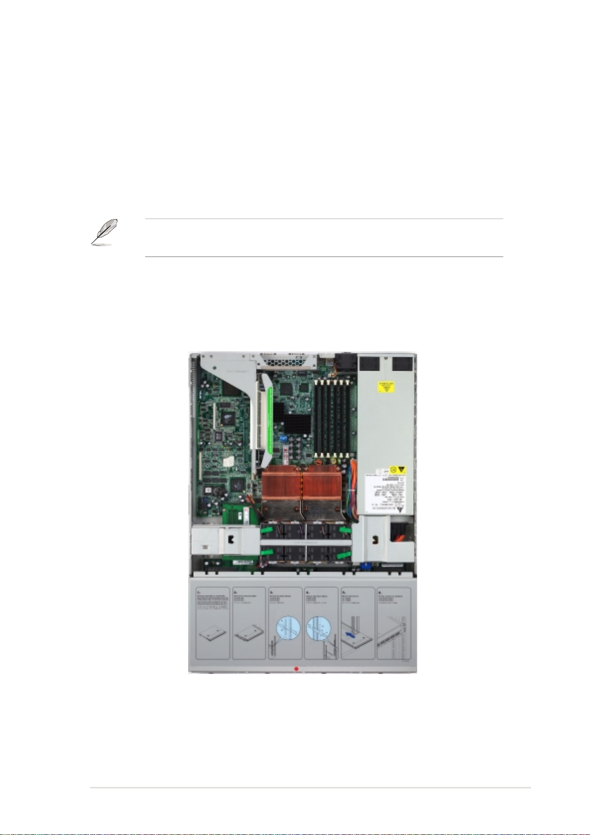
The PR-DLSR is pre-installed in the ASUS AP1600R 1U barebone
server system.
The figure below shows the top view of the PR-DLSR motherboard
installed in the 1U system.
®
Xeon™ processors in 603/604-pin
ASUS PR-DLSR motherboard user guide
1-1

1.2 Special features
1.2.1 Product highlights
Latest processor technology
The PR-DLSR motherboard supports dual Intel® Xeon™ processors via
604-pin surface mount ZIF sockets. The processor features the Intel
NetBurst™ micro-architecture that includes hyper-pipelined technology, a
rapid execution engine, a 400MHz system bus, and an execution trace cache
to offer a significant increase in performance. See page 2-4 for more
information.
DDR memory support
Employing the Double Data Rate (DDR) memory technology, the
PR-DLSR motherboard supports up to 12GB of system memory using
PC2100/1600 registered ECC DDR DIMMs. The ultra-fast 200MHz
memory bus doubles the speed of the PC100 SDRAM to deliver the
required bandwidth for the latest Internet applications. See page 2-7.
®
Dual-channel Ultra-160 SCSI
The LSI® 53C1010R 64-bit/66MHz PCI SCSI controller is onboard to
support dual-channel Ultra-160 SCSI connectors that provide high-speed
data transfer interfaces.
Advanced 64-bit PCI-X slots
The 64-bit/133MHz expansion slot onboard supports a proprietary riser
card with two PCI-X slots (on both sides). The PCI-X slots maximize I/O
bandwidth for the next generation 64-bit PCI-X cards that support
133/100MHz bus. The PCI-X specification 1.0a allows full peer-to-peer
transactions between PCI buses and provides options for intelligent I/O
and server management cards.
Onboard LAN
The motherboard comes with the Intel® 82551QM Fast Ethernet controller
and the Intel® 82544GC Gigabit Ethernet controller to support the latest
LAN technologies.
1-2
Chapter 1: Product introduction

Onboard VGA
The ATI Rage-XL PCI-based VGA controller integrates an 8MB display
SDRAM to provide onboard video solution.
Integrated IDE bridge
The motherboard includes two connectors to support an IDE board with
dual-channel bus master IDE connectors. The IDE connectors support
Ultra DMA 66/33, PIO modes 3 & 4 devices.
ASUS PR-DLSR motherboard user guide
1-3

1.2.2 Value-added solutions
Temperature, fan, and voltage monitoring
The CPU temperature is monitored by the ASUS ASIC to prevent
overheating and damage. The system fan rotations per minute (RPM) is
monitored for timely failure detection. The system voltage levels are
monitored to ensure stable supply of current for critical components.
Dual function power switch
While the system is ON, pressing the power switch for less than 4 seconds
puts the system to sleep mode or to soft-off mode, depending on the BIOS
setting. Pressing the power switch for more than 4 seconds lets the
system enter the soft-off mode regardless of the BIOS setting.
Remote Ring In
This feature allows the system to wake up remotely through an internal or
external modem, if present.
Wake-Up support
The motherboard includes Wake-On-LAN, Wake-On-Ring, and BIOS
Wake-Up features.
Server management
The motherboard comes with an ASMC connector that supports the
optional ASMC-HE/ME/LE card to comply with server reliability, availability,
and serviceability requirements. Remote management response via
remote diagnostics and troubleshooting still works even when the
operating system has stopped functioning.
ACPI ready
The Advanced Configuration power Interface (ACPI) provides more energy
saving features for operating systems that support OS Direct Power
Management (OSPM).
Concurrent PCI
This feature allows multiple PCI transfers from PCI master buses to the
memory and processor.
1-4
Chapter 1: Product introduction

Chassis intrusion detection
The motherboard supports chassis intrusion monitoring through the ASUS
ASIC. A chassis intrusion event is retained in the system memory for more
protection.
Smart BIOS
The 4Mbit firmware gives an easy-to-use interface that provides more
control and protection to the motherboard. The BIOS has a boot block
write protection and supports BIOS Boot Specification (BBS).
Compliance
Both the BIOS and the hardware levels of the motherboard meet the
stringent requirements for SDG 2.0 certification. The new SDG 2.0
requirements for systems and components are based on the following
high-level goals: support for Plug-and-Play compatibility and power
management for configuring and managing all system components, 32-bit
device drivers, and installation procedures for Windows NT/2000/XP.
Color-coded connectors and descriptive icons make identification easy as
required by the PC ‘99 specification.
ASUS PR-DLSR motherboard user guide
1-5

1.3 Motherboard overview
Before you install the PR-DLSR motherboard, familiarize yourself with its
physical configuration and available features to facilitate the motherboard
installation and future upgrades. A sufficient knowledge of the motherboard
specifications will also help you avoid mistakes that may damage the
board and its components.
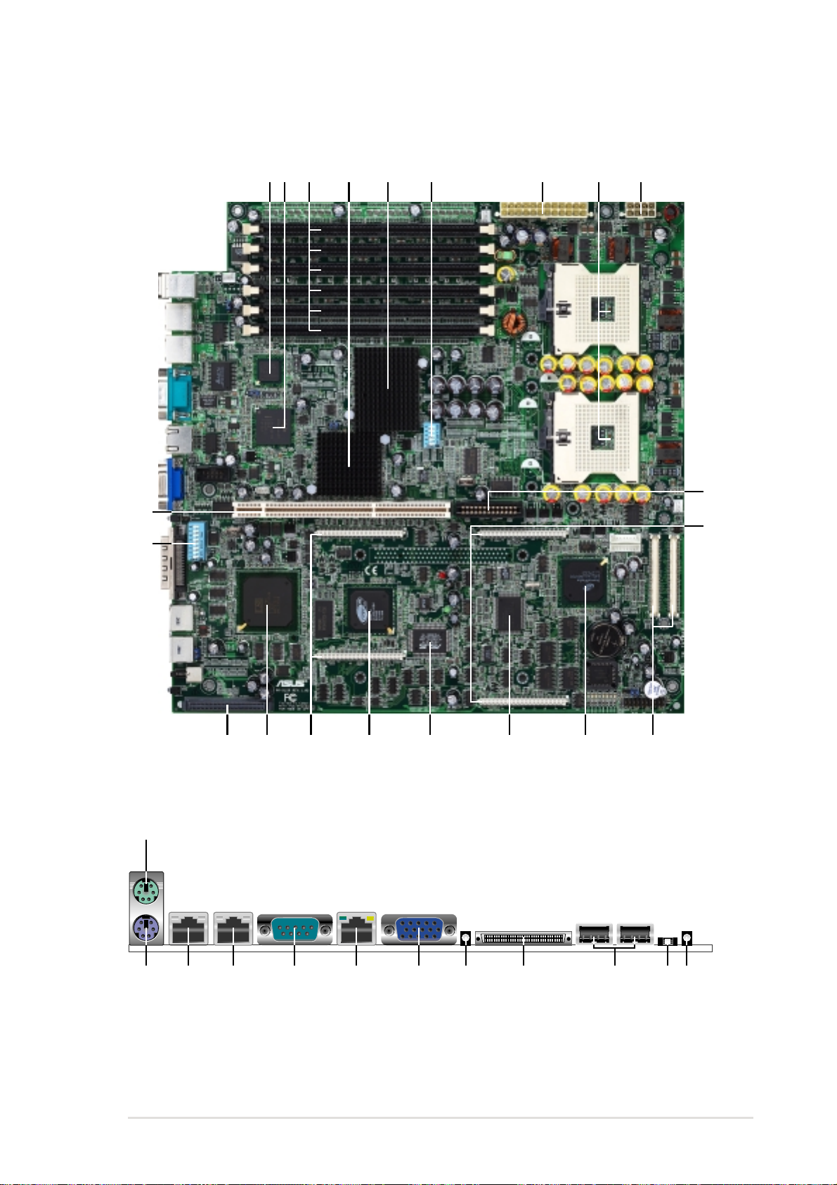
1.3.1 Major components
The following are the major components of the PR-DLSR motherboard as
pointed out in the picture on page 1-7.
1. Intel® 82551QM Fast Ethernet
controller
®
2. Intel
3. DDR DIMM sockets
4. ServerWorks
5. ServerWorks
6. 5-switch DIP (SW1)
7. 24-pin ATX power connector
8. 604-pin CPU sockets
9. 8-pin 12V SSI power connector
10. PCI extended power connector
11. Server management
12. Backplane bridge board
13. ServerWorks
82544GC Gigabit Ethernet
controller
®
64-bit I/O Bridge
(CIOB-X2)
®
Grand Champion
LE North Bridge (CMIC-LE)
daughterboard connectors
connectors
®
Champion South
Bridge (CSB5)
16. ATI Rage-XL VGA controller
17. Zero-channel RAID connectors
®
18. LSI
19. Ultra-160 SCSI connector
20. 8-switch DIP (SW2)
21. 64-bit 133/100MHz PCI slot
22. PS/2 mouse port
23. PS/2 keyboard port
24. RJ-45 port (100/10 Mbps)
25. RJ-45 port (1000/100/10 Mbps)
26. Serial port
27. RJ-45 port (for server
28. VGA port
29. SCSI LED
30. High-density SCSI connector
31. USB 1.1 ports
32. Location switch
SCSI controller
(internal)
management)
1-6
14. LPC super I/O controller
15. ASUS ASIC
See page 1-8 for the specifications of each component. Refer to
Chapter 2 for detailed information on the components.
33. Location LED
Chapter 1: Product introduction
21
20
31 5 8 9
42
6
7
10
11
19
22
24 25 26 27 28 29 30 31 32 33
23
17
1618 14
ASUS PR-DLSR motherboard user guide
1315
12
1-7

1.3.2 Core specifications
®
1
Intel
supports 10BASE-T/100BASE-TX networking protocols.
82551QM Fast Ethernet controller. This LAN controller fully
2
Intel
®
82544GC Gigabit Ethernet controller. This controller is an
integrated Ethernet LAN component that supports 1000Mbps,
100Mbps, and 10Mbps data rates. The 82544GC is optimized for
LAN on Motherboard designs (LOM), enterprise networking, and
Internet appliances that use PCI or PCI-X bus. The controller
provides a 32/64-bit, 33/66MHz interface to the PCI bus that
supports PCI Specification Rev. 2.2, and to the PCI-X extension to
the PCI Local Bus Rev 1.0a at clock rates of up to 133MHz.
3
DDR DIMM sockets. These six 184-pin DIMM sockets support up
to 12GB system memory using registered ECC PC2100/1600 DDR
DIMMs.
4
ServerWorks
®
64-bit I/O Bridge (CIOB-X2). The Champion I/O
Bridge (CIOB-X2) provides a high performance data flow path
between the IMB and the I/O subsystem, which supports multiple
PCI/PCI-X interfaces that allows large, efficient, and flexible I/O
configurations. The CIOB-X2 supports 64-bit PCI/PCI-X I/O buses
that comply with PCI 2.2 specification.
5
ServerWorks
®
Grand Champion LE north bridge (CMIC-LE).
The Champion Memory and I/O Controller LE (CMIC-LE) acts as
the host bridge of the Grand Champion Low End (GCLE)
SystemSet. The CMIC-LE device interfaces directly to the
processor bus, and integrates the functions of the main memory
controller and the Inter Module Bus (IMB) interface unit. The
processor interface supports a 400MHz Front Side Bus (FSB)
providing a 3.2GB/s bandwidth, 2-way interleaved 3.2GB/s memory
bandwidth with up to 12GB registered PC2100/1600 DDR DIMMs,
and two high speed IMBs plus one thin IMB to connect to the south
bridge CSB5.
6
5-switch DIP (SW1). This 5-switch Dual Inline Package (DIP)
allows you to set the CPU external frequency.
7
24-pin ATX power connector. This power connector is for an ATX
power supply.
8
604-pin CPU sockets. Two 604-pin surface mount, Zero Insertion
Force (ZIF) sockets for the Intel
®
Xeon™ processors with a 400
MHz system bus that allows up to 3.2GB/s data transfer rate.
1-8
Chapter 1: Product introduction

9
8-pin 12V SSI power connector. This power connector is for an
SSI-type power supply.
10
11
12
13
14
PCI extended power connector. This connector provides the
additional power required by PCI cards.
Server management daughterboard connectors. These
connectors are for the optional ASUS Server Management
daughterboards.
Backplane bridge board connectors. These connectors are for
the bridge board that connects the motherboard to the backplane
board.
ServerWorks
®
Champion south bridge (CSB5). The Champion
South Bridge (CSB5) primarily acts as a PCI to Low Pin Count
(LPC) bridge, but also supports several integrated functions
including dual-channel ATA/100 IDE controller, 4-port USB 1.1
interface, ACPI power management and detection, XIO-APIC, and
legacy functions 8237DMA, 8259APIC, and 8254 timer.
LPC super I/O controller. This Low Pin Count (LPC) interface
provides the commonly used Super I/O functionality. The chipset
supports UART compatible serial ports, one parallel port with EPP
and ECP capabilities, a floppy drive, and PS/2 keyboard and
mouse.
15
16
17
18
19
ASUS ASIC. This chip monitors, examines, and manages system
status information including CPU and system voltages,
temperature, and fan speeds.
ATI Rage-XL VGA controller. This PCI-based VGA controller
supports up to 8MB display SDRAM for 1280x1024 and true color
resolutions.
Zero-Channel RAID connectors. These connectors are for a
RAID daughterboard that supports advanced RAID functionality.
®
LSI
SCSI controller. The LSI 53C1010R SCSI controller supports
up to 30 SCSI devices through the onboard dual-channel SCSI
connectors.
Ultra-160 SCSI connector (internal). This dual-channel 68-pin
Ultra-160 SCSI connector supports up to 30 SCSI devices, and
data transfers of 160Mbps.
ASUS PR-DLSR motherboard user guide
1-9

20
8-switch DIP (SW2). This 8-switch Dual Inline Package (DIP)
allows you to select the CPU frequency multiple.
21
22
23
24
25
26
27
64-bit 133/100MHz PCI slot. This PCI expansion slot is for the
proprietary riser card with dual PCI-X slots. The PCI-X slots support
bus master PCI-X/PCI cards.
PS/2 mouse port. This green 6-pin connector is for a PS/2 mouse.
PS/2 keyboard port. This purple 6-pin connector is for a PS/2
keyboard.
RJ-45 port (100/10 Mbps). This port allows connection to a Local
Area Network (LAN) through a network hub to support 10BASE-T/
100BASE-TX networking protocols.
RJ-45 port (1000/100/10 Mbps). This port allows connection to a
Local Area Network (LAN) through a network hub to support up to
1000Mbps data transfer rates.
Serial port. This 9-pin COM1 port is for pointing devices or other
serial devices.
RJ-45 port (for server management). This port allows connection
to a Local Area Network (LAN) through a network hub to support
the remote power management feature.
28
29
30
31
32
33
VGA port. This port is for a VGA-monitor or other VGA-compatible
devices.
SCSI LED. This LED indicates the status of the SCSI device
connected to the external SCSI connector.
High-density SCSI connector. This dual-channel 68-pin Ultra-160/
320 SCSI connector supports up to 30 SCSI devices, and data
transfers of 160Mbps/320Mbps.
USB 1.1 ports. These two 4-pin Universal Serial Bus (USB) ports
are available for connecting USB devices.
Location switch. Pressing this switch causes the location LED to
light up, allowing you to locate a specific 1U system when several
system are installed in a rack. This switch has a counterpart on the
front panel. When you press either the front or rear panel location
switch, the location LED on both the front and rear panels light up.
Location LED. This LED indicates the specific 1U system installed
on a rack.
1-10
Chapter 1: Product introduction
Chapter 2
This chapter describes the hardware setup
procedures that you have to perform when
installing system components. It includes
details on the switches, jumpers, and
connectors on the motherboard.
Hardware information

Chapter summary
2.1 Motherboard installation ............................... 2-1
2.2 Motherboard layout ....................................... 2-2
2.3 Before you proceed ....................................... 2-3
2.4 Central Processing Unit (CPU) ..................... 2-4
2.5 System memory ............................................. 2-7
2.6 Expansion slots ........................................... 2-10
2.7 Switches ....................................................... 2-12
2.8 Connectors ................................................... 2-17
ASUS PR-DLSR motherboard
2.1 Motherboard installation
Before you install the motherboard, study the configuration of your chassis
to ensure that the motherboard fits into it. The PR-DLSR uses the
extended ATX form factor that measures 12 x 12 inches (30.5 x 30.5 cm).
Make sure to unplug the power cord before installing or removing the
motherboard. Failure to do so may cause you physical injury and
damage motherboard components.
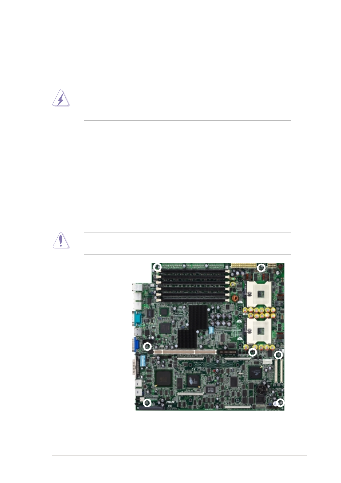
2.1.1 Placement direction
When installing the motherboard, make sure that you place it into the
chassis in the correct orientation. The edge with external ports goes to the
rear part of the chassis as indicated in the image below.
2.1.2 Screw holes
Place seven (7) screws into the holes indicated by circles to secure the
motherboard to the chassis.
Do not overtighten the screws! Doing so may damage the
motherboard.
Place this side towards
the rear of the chassis
ASUS PR-DLSR motherboard user guide
2-1
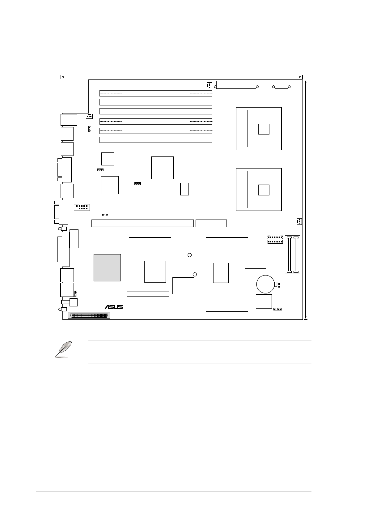
2.2 Motherboard layout
30.5cm (12in)
PS/2
FAN1
T: Mouse
B: Keyboard
LAN100
LAN1G
COM1
ERMCCON
VGA
SCSI_LED
SW2
SCSI-B
USBX1
USBX2
SCSI
LOCSW
LOCLED
34 1
DDR DIMM1 (72 bit, 184-pin module)
DDR DIMM2 (72 bit, 184-pin module)
DDR DIMM3 (72 bit, 184-pin module)
DDR DIMM4 (72 bit, 184-pin module)
J1
DDR DIMM5 (72 bit, 184-pin module)
DDR DIMM6 (72 bit, 184-pin module)
Intel
82551
Fast
Ethernet
J3
Intel
82544GC
Gigabit
Ethernet
ServerWorks
COM2
WOL_CON
PCI1 (Proprietary expansion slot)
®
LSI 53C1010R
SCSI
Controller
PR-DLSR
3568
2U-SCSI
®
LAN1G
CIOB-X2
I/O Bridge
ZCRA1
RAGE XL
Controller
ZCRB1
ServerWorks
CNB GCLE
North Bridge
®
ATI
VGA
®
ASUS
ASIC
with Hardware
Monitor
SW1
LED1
FAN2
PCI_EXTPWR
LED2
EATXPOWER
ERMCA
I/O
Super
ERMCB
mPGA604mPGA604
SYSFAN1
SYSFAN2
®
ServerWorks
RCC CSB5
South Bridge
CR2032 3V
Lithium Cell
CMOS Power
4Mbit
Flash
BIOS
EX12VCON
30.5cm (12 in)
FAN4
BPCON
J7
CHASSIS
2-2
The SCSI features are optional. These components are grayed out in
the above motherboard layout.
Chapter 2: Hardware information
2.3 Before you proceed
Take note of the following precautions before you install motherboard
components or change any motherboard settings.
1. Unplug the power cord from the wall socket before touching any
component.
2. Use a grounded wrist strap or touch a safely grounded object or to
a metal object, such as the power supply case, before handling
components to avoid damaging them due to static electricity.
3. Hold components by the edges to avoid touching the ICs on them.
4. Whenever you uninstall any component, place it on a grounded
antistatic pad or in the bag that came with the component.
5. Before you install or remove any component, ensure that the
ATX power supply is switched off or the power cord is
detached from the power supply. Failure to do so may cause
severe damage to the motherboard, peripherals, and/or
components.
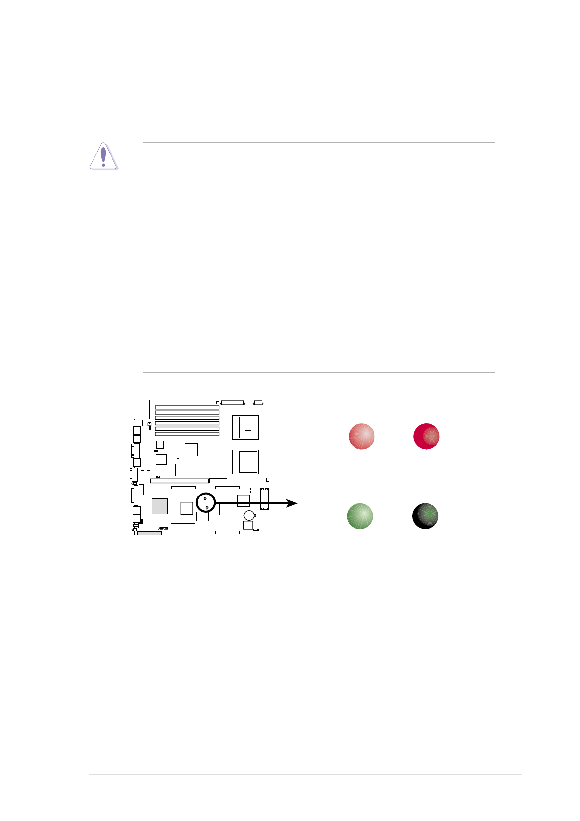
PR-DLSR
®
PR-DLSR Onboard LED
LED1 (RED)
ON
CPU installed
incorrectly
LED2 (GREEN)
ON
Standby
Power
OFF
CPU installed
correctly
OFF
Powered
Off
ASUS PR-DLSR motherboard user guide
2-3
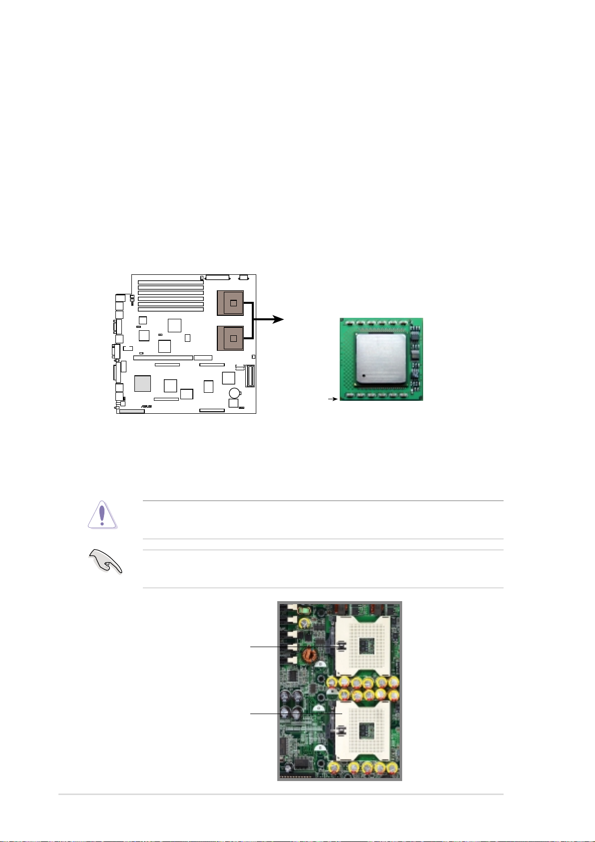
2.4 Central Processing Unit (CPU)
2.4.1 Overview
The motherboard comes with dual surface mount 604-pin Zero Insertion
Force (ZIF) sockets. The sockets are designed for the Intel® Xeon™
Processor in the 603/604-pin package. The processor includes the Intel
NetBurst™ micro-architecture that features the hyper-pipelined
technology, rapid execution engine, 400MHz system bus, and execution
trace cache. Together, these attributes improve system performance by
allowing higher core frequencies, faster execution of integer instructions,
and data transfer rate of up to 3.2GB/s.
Xeon Processor
PR-DLSR
®
PR-DLSR Socket 604
Gold Mark
Note in the illustration that the CPU has a gold triangular mark on one
corner. This mark indicates the processor Pin 1 that should match a
specific corner of the CPU socket.
Incorrect installation of the CPU into the socket may bend the pins and
severely damage the CPU!
The motherboard supports either one or two CPUs. If you are installing
only one CPU, you MUST install it in CPU socket 1.
CPU Socket 1
(outer socket)
2-4
CPU Socket 2
(inner socket)
Chapter 2: Hardware information
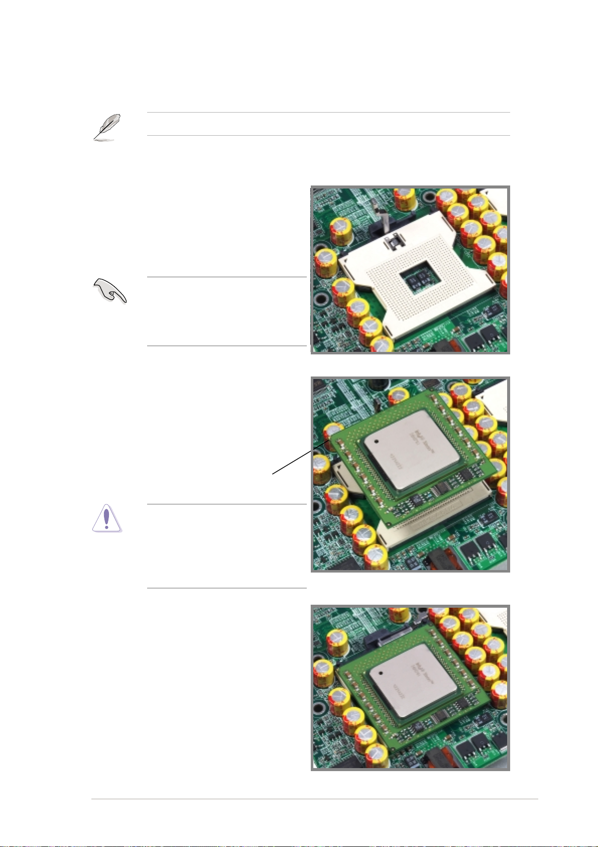
2.4.2 Installing the CPU
If you are installing two CPUs, install in the CPU socket 2 first.
Follow these steps to install a CPU.
1. Locate the 604-pin ZIF sockets on
the motherboard. Unlock the
socket by pressing the lever
sideways, then lift it up to at least
115° angle.
Make sure that the socket
lever is lifted up to at least
115° angle, otherwise the CPU
does not fit in completely.
2. Position the CPU above the
socket as shown.
3. Carefully insert the CPU into the
socket until it fits in place.
Marked Corner
The CPU fits only in one
correct orientation. DO NOT
force the CPU into the socket
to prevent bending the pins
and damaging the CPU!
4. When the CPU is in place, press it
firmly on the socket while you
push down the socket lever to
secure the CPU. The lever clicks
on the side tab to indicate that it is
locked.
ASUS PR-DLSR motherboard user guide
2-5
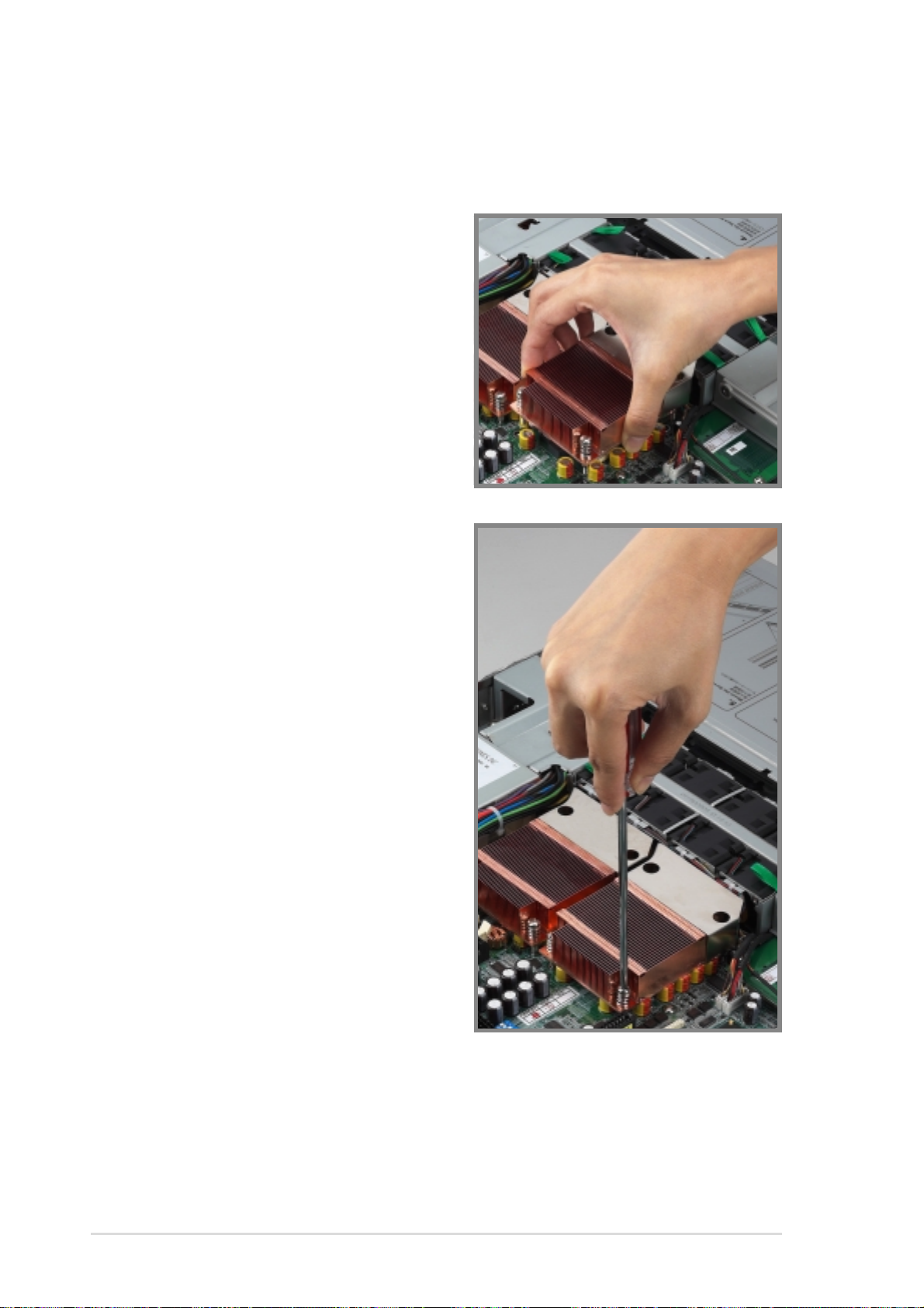
2.4.3 Installing the heatsink
Follow these steps to install the CPU heatsink.
1. Carefully place the heatsink on top
of the installed CPU. The heatsink
fits in only one orientation. Take
note of the heatsink placement as
shown.
2. Use a Phillips screwdriver to twist
each of the four screws to secure
the heatsink to the motherboard.
2-6
Chapter 2: Hardware information
 Loading...