

Asus PE200U User’s Manual

PE200U Series
Desktop PC
User Manual

E17346
Revised Edition V3
November 2020
COPYRIGHT INFORMATION
No part of this manual, including the products and software described in it, may be reproduced,
transmitted, transcribed, stored in a retrieval system, or translated into any language in any form or by
any means, except documentation kept by the purchaser for backup purposes, without the express
written permission of ASUSTeK COMPUTER INC. (“ASUS”).
ASUS PROVIDES THIS MANUAL “AS IS” WITHOUT WARRANTY OF ANY KIND, EITHER EXPRESS
OR IMPLIED, INCLUDING BUT NOT LIMITED TO THE IMPLIED WARRANTIES OR CONDITIONS OF
MERCHANTABILITY OR FITNESS FOR A PARTICULAR PURPOSE. IN NO EVENT SHALL ASUS, ITS
DIRECTORS, OFFICERS, EMPLOYEES OR AGENTS BE LIABLE FOR ANY INDIRECT, SPECIAL, INCIDENTAL,
OR CONSEQUENTIAL DAMAGES (INCLUDING DAMAGES FOR LOSS OF PROFITS, LOSS OF BUSINESS,
LOSS OF USE OR DATA, INTERRUPTION OF BUSINESS AND THE LIKE), EVEN IF ASUS HAS BEEN ADVISED
OF THE POSSIBILITY OF SUCH DAMAGES ARISING FROM ANY DEFECT OR ERROR IN THIS MANUAL OR
PRODUCT.
Products and corporate names appearing in this manual may or may not be registered trademarks or
copyrights of their respective companies, and are used only for identication or explanation and to
the owners’ benet, without intent to infringe.
SPECIFICATIONS AND INFORMATION CONTAINED IN THIS MANUAL ARE FURNISHED FOR
INFORMATIONAL USE ONLY, AND ARE SUBJECT TO CHANGE AT ANY TIME WITHOUT NOTICE, AND
SHOULD NOT BE CONSTRUED AS A COMMITMENT BY ASUS. ASUS ASSUMES NO RESPONSIBILITY OR
LIABILITY FOR ANY ERRORS OR INACCURACIES THAT MAY APPEAR IN THIS MANUAL, INCLUDING THE
PRODUCTS AND SOFTWARE DESCRIBED IN IT.
Copyright © 2020 ASUSTeK COMPUTER INC. All Rights Reserved.
LIMITATION OF LIABILITY
Circumstances may arise where because of a default on ASUS’ part or other liability, you are entitled to
recover damages from ASUS. In each such instance, regardless of the basis on which you are entitled
to claim damages from ASUS, ASUS is liable for no more than damages for bodily injury (including
death) and damage to real property and tangible personal property; or any other actual and direct
damages resulted from omission or failure of performing legal duties under this Warranty Statement,
up to the listed contract price of each product.
ASUS will only be responsible for or indemnify you for loss, damages or claims based in contract, tort
or infringement under this Warranty Statement.
This limit also applies to ASUS’ suppliers and its reseller. It is the maximum for which ASUS, its
suppliers, and your reseller are collectively responsible.
UNDER NO CIRCUMSTANCES IS ASUS LIABLE FOR ANY OF THE FOLLOWING: (1) THIRD-PARTY
CLAIMS AGAINST YOU FOR DAMAGES; (2) LOSS OF, OR DAMAGE TO, YOUR RECORDS OR DATA; OR (3)
SPECIAL, INCIDENTAL, OR INDIRECT DAMAGES OR FOR ANY ECONOMIC CONSEQUENTIAL DAMAGES
(INCLUDING LOST PROFITS OR SAVINGS), EVEN IF ASUS, ITS SUPPLIERS OR YOUR RESELLER IS
INFORMED OF THEIR POSSIBILITY.
SERVICE AND SUPPORT
Visit our multi-language web site at https://www.asus.com/support/

Contents
About this manual .................................................................................................................6
Conventions used in this manual ..............................................................................................7
Typography .......................................................................................................................................7
Package contents ..................................................................................................................8
Chapter 1: Getting to know your Edge Computer
1.1 Features ..........................................................................................................................12
1.1.1 Front view ............................................................................................................................12
1.1.2 Rear view ..............................................................................................................................14
1.2 Motherboard Overview ............................................................................................16
1.2.1 Motherboard layout .........................................................................................................16
1.2.2 System memory .................................................................................................................18
1.2.3 Onboard jumpers ..............................................................................................................19
1.2.4 Internal connectors ..........................................................................................................22
Chapter 2: Using your Edge Computer
2.1 Getting started .............................................................................................................36
2.1.1 Connect the AC power adapter to your Edge Computer ...................................36
2.1.2 Connect a display panel to your Edge Computer .................................................38
2.1.3 Connect the USB cable from keyboard or mouse .................................................40
2.1.4 Turn on your Edge Computer .......................................................................................41
2.2 Turning your Edge Computer o...........................................................................42
2.3 Putting your Edge Computer to sleep .................................................................42
2.4 Entering the BIOS Setup ...........................................................................................42
2.4.1 Load default BIOS settings .............................................................................................43
PE200U Series
3

Chapter 3: Upgrading your Edge Computer
3.1 Removing the bottom cover ...................................................................................46
3.2 Replacing the bottom cover ...................................................................................47
3.3 Installing memory modules ....................................................................................48
3.4 Installing 2.5” storage device ..................................................................................49
3.5 Installing the Mini PCIe or mSATA card ...............................................................51
3.6 Installing a nano SIM card ........................................................................................52
3.7 Installing an SD card...................................................................................................53
3.8 Installing the wireless card ......................................................................................55
3.9 Installing an M.2 SSD..................................................................................................56
3.10 Installing the antennas (optional) .........................................................................57
3.11 Installing the USB 2.0 module (on selected models) ......................................58
3.12 Installing the Serial port module (on selected models) ................................59
3.13 Installing the PoE LAN module (on selected models) ....................................60
3.14 Installing the VESA mount(optional) ....................................................................62
3.15 Installing the wall mount .........................................................................................64
Chapter 4: Using the software
4.1 Installing IEC Vision .....................................................................................................66
4.2 IEC Vision overview .....................................................................................................69
4.2.1 Demographic Mode .........................................................................................................69
4.2.2 Dashboard ...........................................................................................................................71
4.3 Conguring the camera ............................................................................................72
4.3.1 Conguring a USB camera .............................................................................................72
4.3.2 Conguring a PoE IP camera .........................................................................................74
Chapter 5: Watchdog Timer
5.1 Watchdog Timer implementation .........................................................................78
5.2 Watchdog Timer owchart ......................................................................................80
5.3 Watchdog Timer Programming ..............................................................................81
4
PE200U Series

Appendix
Safety information .................................................................................................................86
Setting up your system .................................................................................................................86
Care during use ................................................................................................................................87
Regulatory notices ................................................................................................................88
ASUS contact information ..................................................................................................95
PE200U Series
5

About this manual
This manual provides information about the hardware and software features
of your Edge Computer, organized through the following chapters:
Chapter 1: Getting to know your Edge Computer
This chapter details the hardware components of your Edge Computer.
Chapter 2: Using your Edge Computer
This chapter provides you with information on using your Edge
Computer.
Chapter 3: Upgrading your Edge Computer
This chapter provides you with information on how to upgrade the
memory modules, wireless modules, and hard disk drive / solid state
drive of your Edge Computer.
Chapter 4: Using the software
This chapter provides you with information on how to install the ASUS
IEC Vision software and also provides a brief summary of the software
layout.
Appendix
This section includes notices and safety statements your Edge
Computer.
6
PE200U Series

Conventions used in this manual
To highlight key information in this manual, some text are presented as
follows:
IMPORTANT! This message contains vital information that must be
followed to complete a task.
NOTE: This message contains additional information and tips that can
help complete tasks.
WARNING! This message contains important information that must be
followed to keep you safe while performing certain tasks and prevent
damage to your Edge Computer's data and components.
Typography
Bold text Indicates a menu or an item to select.
Italic
This indicates sections that you can refer to in this manual.
PE200U Series
7
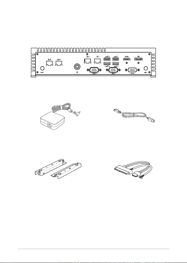
Package contents
Your Edge Computer package contains the following items:
PE200U Series
AC power adapter* Power cord*
Wall mount kit SATA and power cable
8
PE200U Series

NOTE:
• *The bundled power adapter may vary by model and territories.
• Some bundled accessories may vary with dierent models. For
details on these accessories, refer to their respective user manuals.
• The device illustration is for reference only. Actual product
specications may vary with models.
• I f the device or its components fail or malfunction during normal
and proper use within the warranty period, bring the warranty
card to the ASUS Service Center for replacement of the defective
components.
PE200U Series
9


1
Getting to know your Edge
Computer
1.1 Features
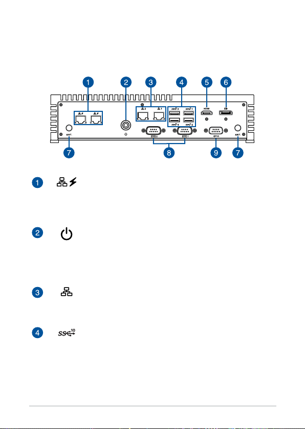
1.1.1 Front view
LAN port with PoE (on selected models)
The 8-pin RJ-45 LAN port supports a standard Ethernet
cable for connection to a local network, and supports
Power over Ethernet (PoE).
Power button
The power button allows you to turn the Edge Computer
on or o. You can use the power button to put your Edge
Computer to sleep mode or press it for four (4) seconds to
force shutdown your Edge Computer.
LAN port
The 8-pin RJ-45 LAN port supports a standard Ethernet
cable for connection to a local network.
USB 3.2 Gen 2 port
The USB 3.2 Gen 2 (Universal Serial Bus) port provides a
transfer rate up to 10 Gbit/s.
12
PE200U Series
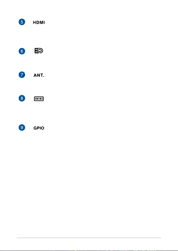
HDMI port
The HDMI (High Denition Multimedia Interface) port
supports a Full-HD device such as an LCD TV or monitor to
allow viewing on a larger external display.
Dual-mode DisplayPort
This port allows you to connect your Edge Computer to an
external display, and supports DVI or HDMI adpaters.
Antenna hole
The antenna hole allows you to connect a wireless
antenna to enhance wireless signal reception.
Serial (COM) connector
The 9-pin RS232/422/485 serial (COM) connector allows
you to connect devices that have serial ports such as bar
code scanner, modem, or printers.
GPIO connector
The 9-pin GPIO (General-purpose Input/Output)
connector allows you to program it for input or output
use, such as lighting control, door control or alarm control.
PE200U Series
13
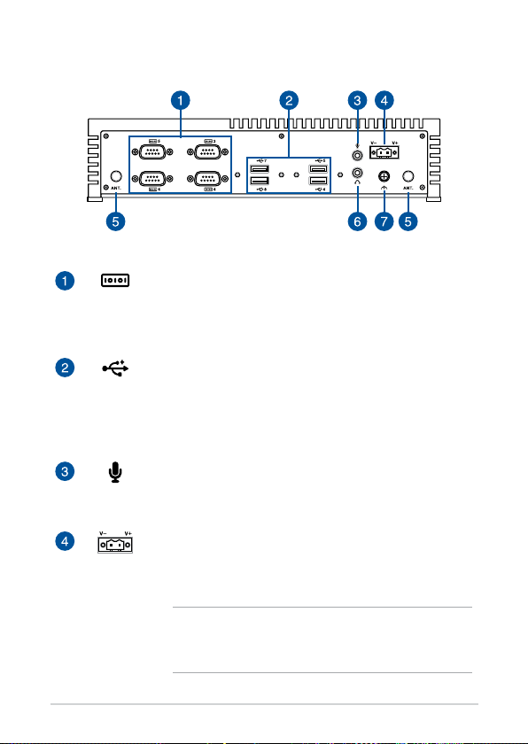
1.1.2 Rear view
Serial (COM) connector (on selected models)
The 9-pin RS-232 serial (COM) connector allows you to
connect devices that have serial ports such as bar code
scanner, modem, or printers.
USB 2.0 port (on selected models)
The USB (Universal Serial Bus) port is compatible with USB
2.0 or USB 1.1 devices such as keyboards, pointing devices,
ash disk drives, external HDDs, speakers, cameras and
printers.
Microphone
The built-in microphone can be used for video
conferencing, voice narrations, or simple audio recording.
Power input
The supplied terminal block power adapter converts AC
power to DC power for use with this jack. Power supplied
through this jack supplies power to the Edge Computer.
14
WARNING! The power adapter may become warm to
hot when in use. Do not cover the adapter and keep
it away from your body.
PE200U Series

Antenna hole
The antenna hole allows you to connect a wireless
antenna to enhance wireless signal reception.
Headphone jack
This port allows you to connect amplied speakers or
headphones.
Functional Earth Ground
The Functional Earth Ground provides you with a
grounding point.
PE200U Series
15
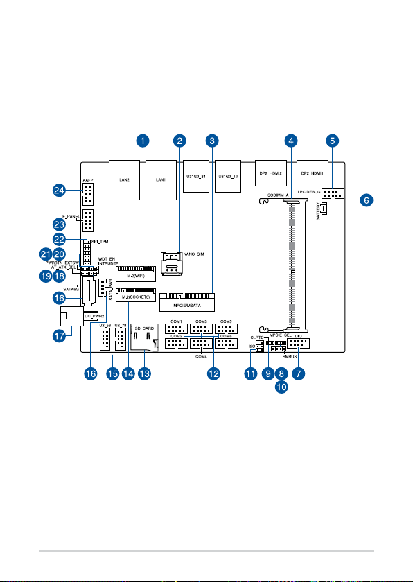
1.2 Motherboard Overview
1.2.1 Motherboard layout
The PE200U Series features a motherboard with a 3.5” dimension (146mm x
105mm).
16
PE200U Series

Layout contents Page
1. M.2 Wi-Fi slot 23
2. Nano SIM Card slot 23
3. Mini PCIe/mSATA slot 21
4. DIMM slot 16
5. Low Pin Count connector 25
6. Battery connector 25
7.. GPIO connector 26
8. Mini PCIe/mSATA conguration jumper 19
9. Clear RTC RAM jumper 17
10. System Management Bus connector 26
11. I2C connector 27
12. Serial Port connector 28
13. Micro SD card slot 22
14. M.2 slot 22
15. USB 2.0 connector 29
16. SATA 6Gb/s & SATA Power connector 20
17. DC-in 4-Pin Power connector 30
18. Chassis Intrusion connector 24
19. AT/ATX Mode Conguration jumper 19
20. HW WDT Enable jumper 18
21. Power button connector 24
22. SPI TPM connector 27
23. System Panel connector 31
24. Line Out / Mic connector 32
PE200U Series
17
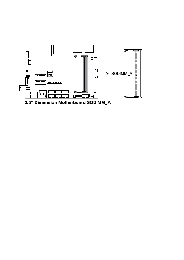
1.2.2 System memory
The motherboard comes with a Small Outline Dual Inline Memory Module
(SODIMM) slot designed for DDR4 (Double Data Rate 4) memory modules.
18
PE200U Series
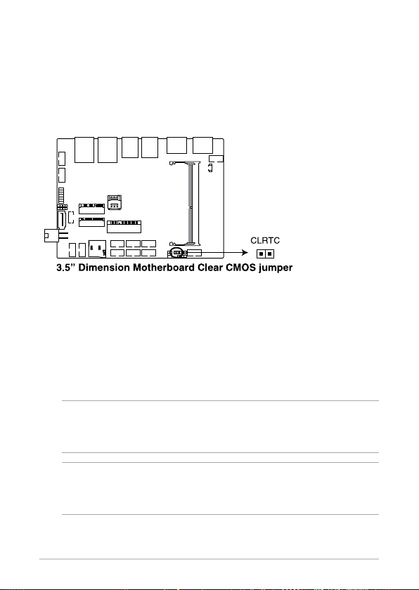
1.2.3 Onboard jumpers
1. Clear RTC RAM jumper
The Clear RTC RAM jumper allows you to clear the Real Time Clock (RTC)
RAM in the CMOS, which contains the date, time, system passwords,
and system setup parameters.
To erase the RTC RAM:
1. Turn OFF the computer and unplug the power cord.
2. Short-circuit pin 1-2 with a metal object or jumper cap for about
5-10 seconds.
3. Plug the power cord and turn ON the computer.
4. Hold down the <Del> key during the boot process and enter
BIOS setup to re-enter data.
WARNING! DO NOT remove the jumper cap from its default position
except when clearing the RTC RAM. Removing the jumper cap will
cause system boot failure!
NOTE: If the steps above do not help, remove the onboard button cell
battery and move the jumper again to clear the CMOS RTC RAM data.
After clearing the CMOS, reinstall the button cell battery.
PE200U Series
19
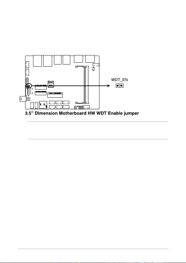
2. HW WDT Enable jumper
A watchdog timer is an electronic timer that is used to detect and
recover from computer malfunctions. The HW WDT (watchdog
timer) Enable jumper allows the HW watchdog resets the system
automatically even when the system crashes.
NOTE: The default setting for this jumper is set to HW WDT enabled
with a jumper cap attached.
20
PE200U Series
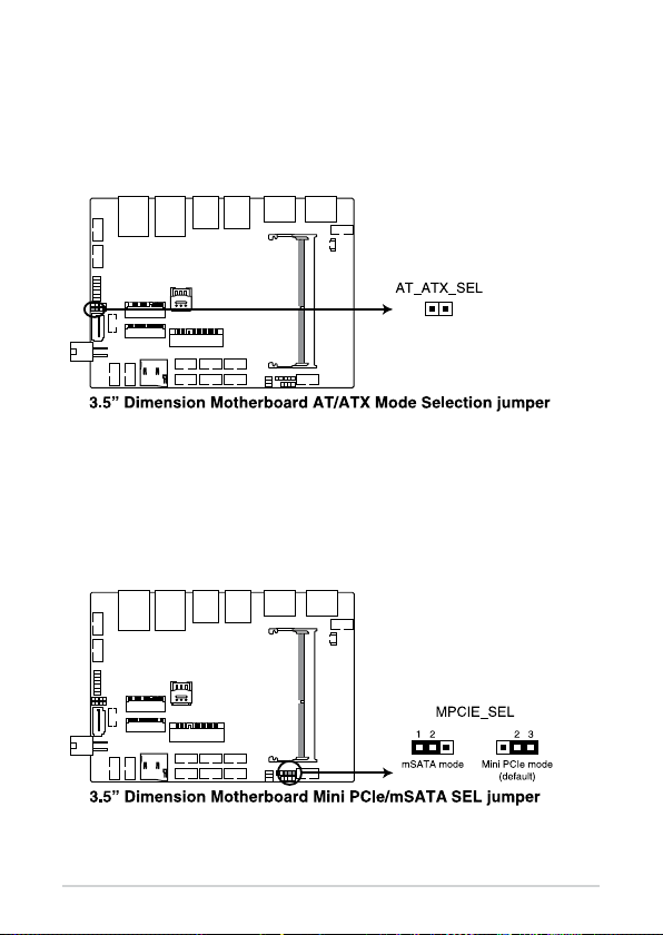
3. AT/ATX Mode Conguration jumper
The AT/ATX Mode Conguration jumper allows you to switch between
AT or ATX modes. The default setting for this jumper is set to ATX mode
with a jumper cap attached, to switch to AT mode, remove the jumper
cap.
4. Mini PCIe/mSATA conguration jumper
The Mini PCIe/mSATA conguration jumper allows you to select
between Mini PCIe mode or mSATA mode. Set to pins 1-2 for mSATA
mode, or set to pins 2-3 for Mini PCIe mode.
PE200U Series
21
1.2.4 Internal connectors
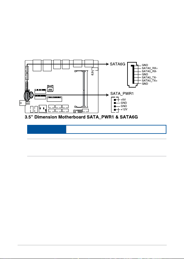
1. SATA 6Gb/s & SATA Power connector
The SATA 6Gb/s and SATA Power connectors allow you to connect SATA
devices such as optical disc drives and hard disk drives via a SATA cable
and power cable.
Connector type
Wafer HD 4P, 2.0mm pitch
NOTE: Ensure to use the bundled cable when connecting a storage
device to this connector.
22
PE200U Series
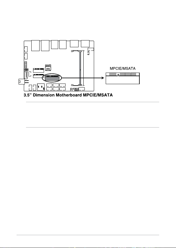
2. Mini PCIe/mSATA slot
The Mini PCIe/mSATA slot allows you to install a Mini PCIe or mSATA
peripheral device.
NOTE:
• The Mini PCIe / mSATA peripheral device is purchased separately.
• The mSATA shares the same slot with a full-length Mini PCIe.
PE200U Series
23
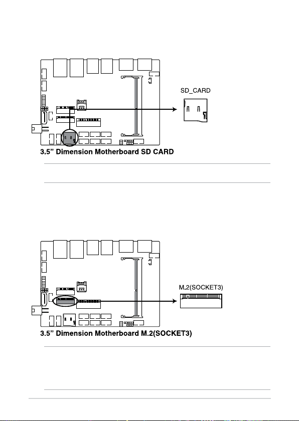
3. Micro SD Card slot
The Micro SD Card slot allows you to install a Micro SD card.
NOTE: The Micro SD card is purchased separately.
4. M.2 slot
The M.2 slot allows you to install 2242 M.2 devices such as 2242 M.2
SSD modules.
NOTE:
• The M.2 SSD module is purchased separately.
• This motherboard supports 2242 PCIE SSD devices only.
24
PE200U Series
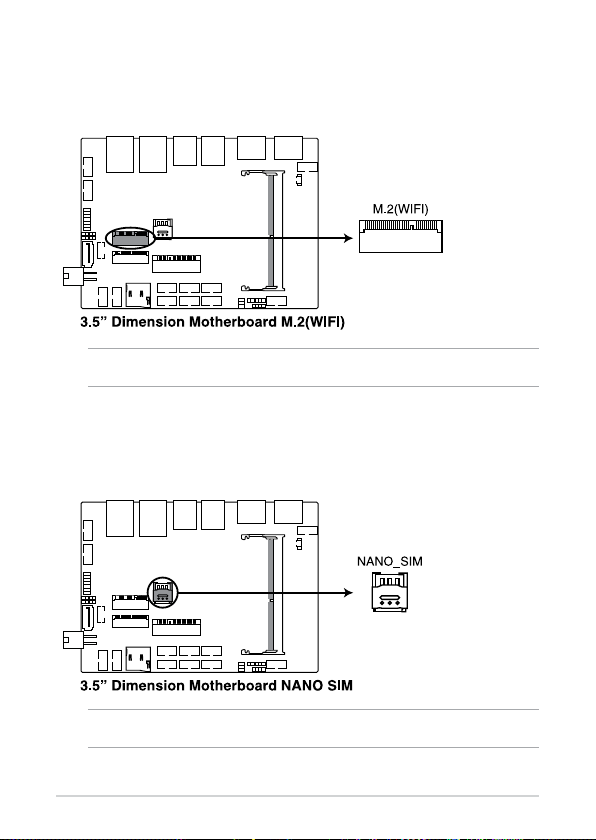
5. M.2 Wi-Fi slot
The M.2 Wi-Fi slot allows you to install an M.2 Wi-Fi module (E-key, type
2230).
NOTE: The M.2 Wi-Fi module is purchased separately.
6. Nano SIM Card slot
The Nano SIM Card slot allows you to install a Nano SIM card.
NOTE: The Nano SIM card is purchased separately.
PE200U Series
25
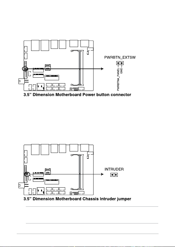
7. Power button connector
The Power Button connector allows you to connect an external power
button.
8. Chassis Intrusion connector
The Chassis Intrusion connector allows you to connect a intrusion
sensor or microswitch for the chassis intrusion detection feature. When
you remove any chassis component, the sensor or microswitch triggers
and sends a high level signal and records a chassis intrusion event.
NOTE: By default, a jumper cap that disables the intrusion detection
feature is installed on the connector to prevent accidental triggers.
26
PE200U Series
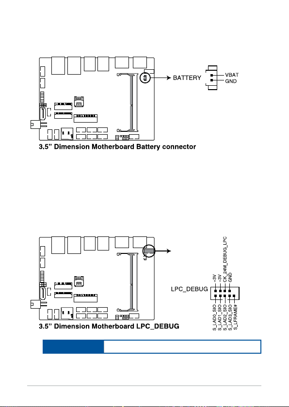
9. Battery connector
The Battery connector allows you to connect the lithium CMOS battery.
10. Low Pin Count connector
The Low Pin Count connector allows you to connect a low pin count
(LPC) debug card that oers a faster, more ecient motherboard
troubleshooting solution. When connected to a debug card, users can
view error and debugging codes on the card and get a better idea of
initialization and recovery processes.
Connector type
BOX header 2x5p, K10, 2.0mm pitch
PE200U Series
27
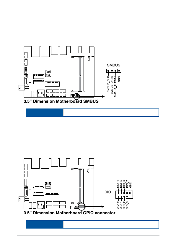
11. System Management Bus connector
The System Management Bus (SMBus) connector allows you to connect
SMBus devices. This connector is generally used for communication
with the system and power management-related tasks.
Connector type
Header 1x4p, 2.0mm pitch
12. GPIO connector
The GPIO connector allows you to connect a general purpose input/
output module which allows you to customize the digital signal input/
output.
28
Connector type
PE200U Series
BOX header 2x5p, K9, 2.0mm pitch
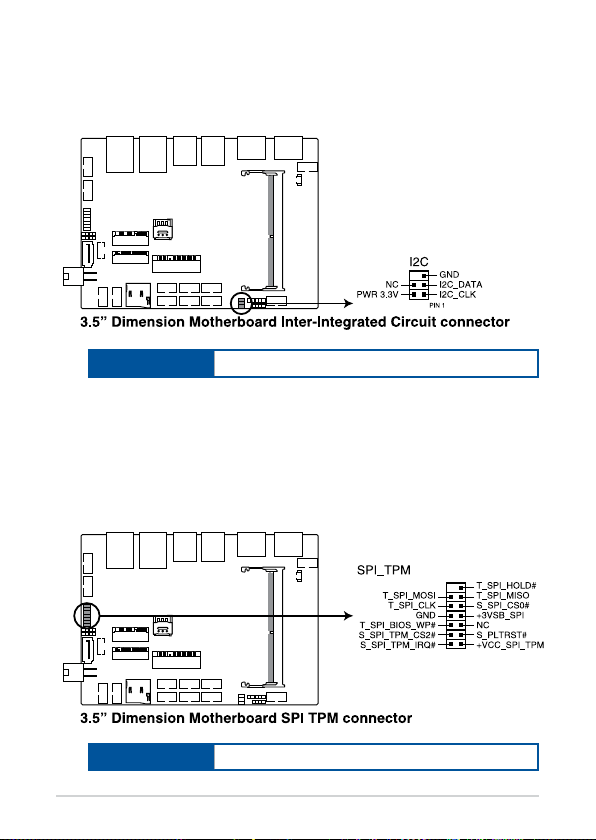
13. I2C connector
The I2C (Inter-Integrated Circuit)connector allows you to connect an
I2C compatible IoT security module.
Connector type
Header 2x3p, K6, 2.0mm pitch
14. SPI TPM connector
The SPI TPM connector supports a Trusted Platform Module (TPM)
system, which can securely store keys, digital certicates, passwords,
and data. A TPM system also helps enhance network security, protects
digital identities, and ensures platform integrity.
Connector type
Header 2x7p,K14, 2.0mm pitch
PE200U Series
29
 Loading...