How it Works
Log In / Sign Up
Buy Points
How it Works
FAQ
Contact Us
Questions and Suggestions
Users
Asus
Loading...
P
PCEAC1N00
PCE-AC56
5
PCE-AC58BT
4
PCE-AC66
2
PCE-AC68
4
PCE-AC88
5
PCE-AX3000
2
PCE-AX58BT
4
PCE-C2500
3
PCE-N10
13
PCE-N13
16
PCE-N15
17
PCE-N53
15
PCH-DL
PCH-DR
PCI-AS300
PCI-AV264CT-N
PCI-AV264GT
PCI-AV264GT/Plus
PCI-AV264VT
PCI CARD
PCI-DA2100
PCI-DA2200
2
PCIE0U00
PCIE-P54NP4
2
PCIe SSD
PCI Express Audio Card Xonar DX
PCI-G31
16
PCI I-486SP3G
2
PCII-A486S
2
PCII-P54NP4
2
PCI I-P54NP4D
2
PCII-P54SP4
2
PCII-P54TP4
2
PCI-L101
PCI-L3C920
PCI-N10
12
PCI-SC875
PCI-SC896
PCI-SIU2
PCI-V264CT
PCI-V264GT
PCI-V264GT/Plus
PCI-V264VT
2
PCI-V775V2
PCI-V775V2C
PD100
PE100A
2
PE2
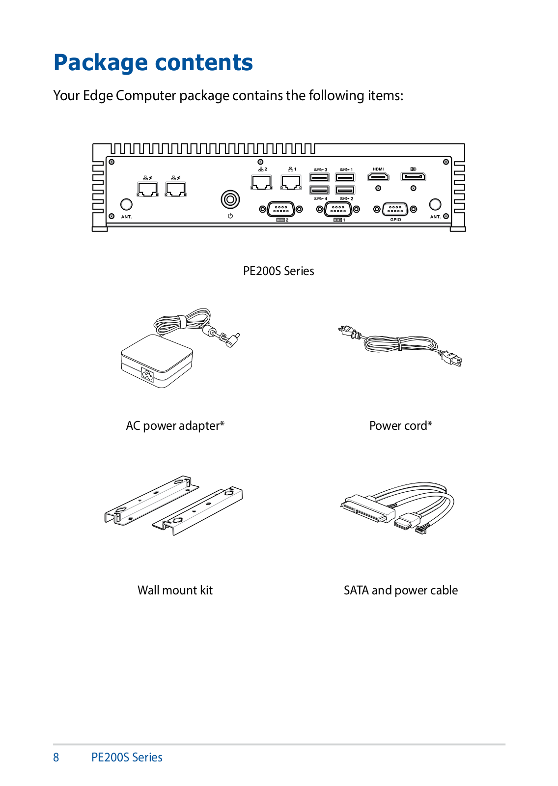
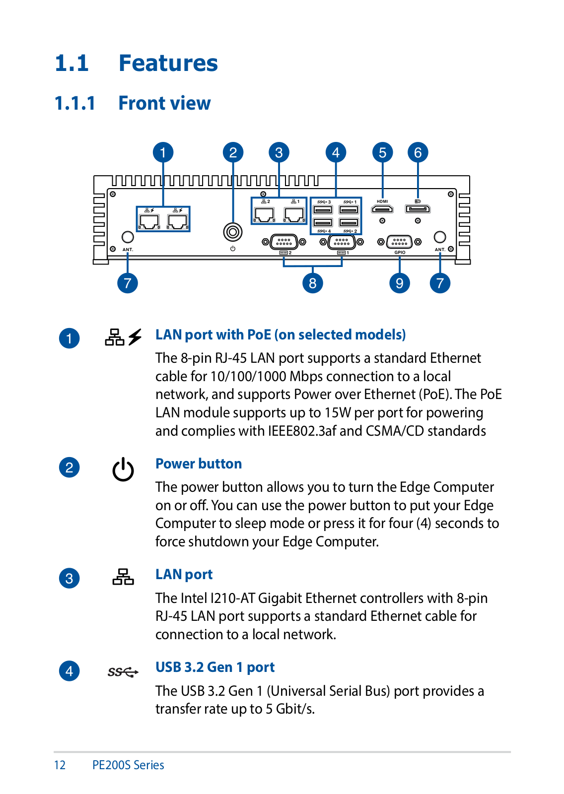
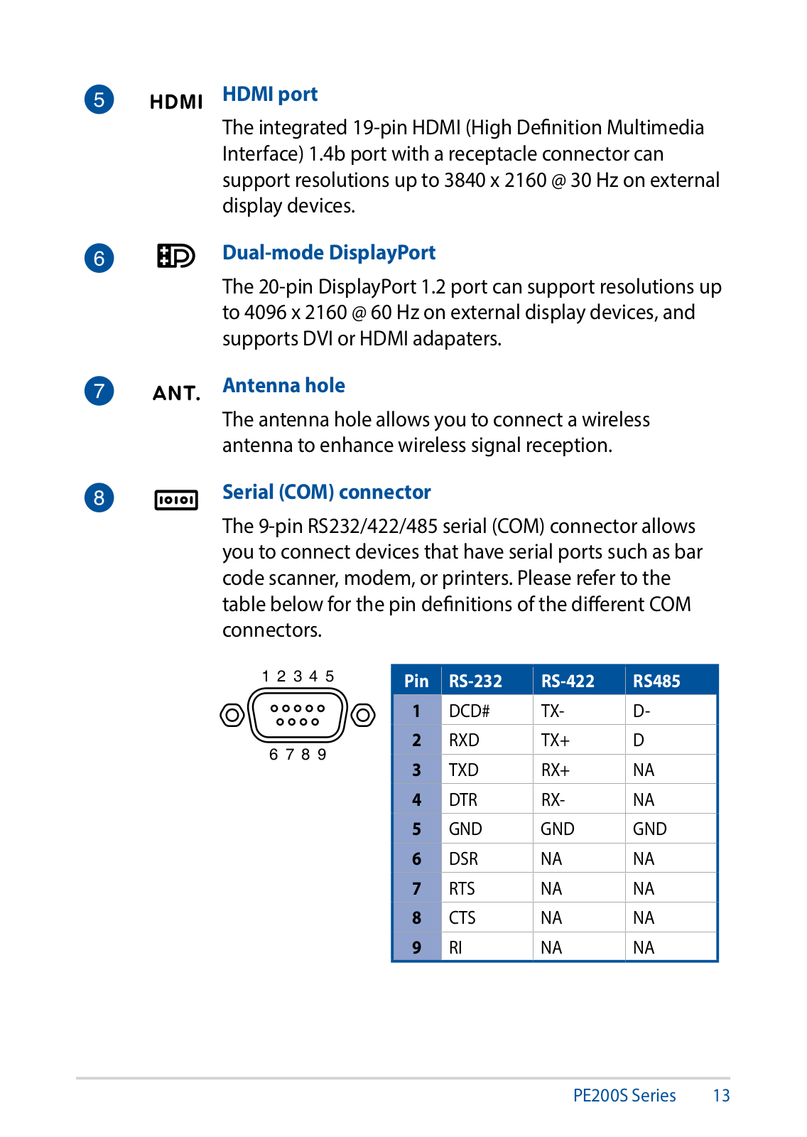
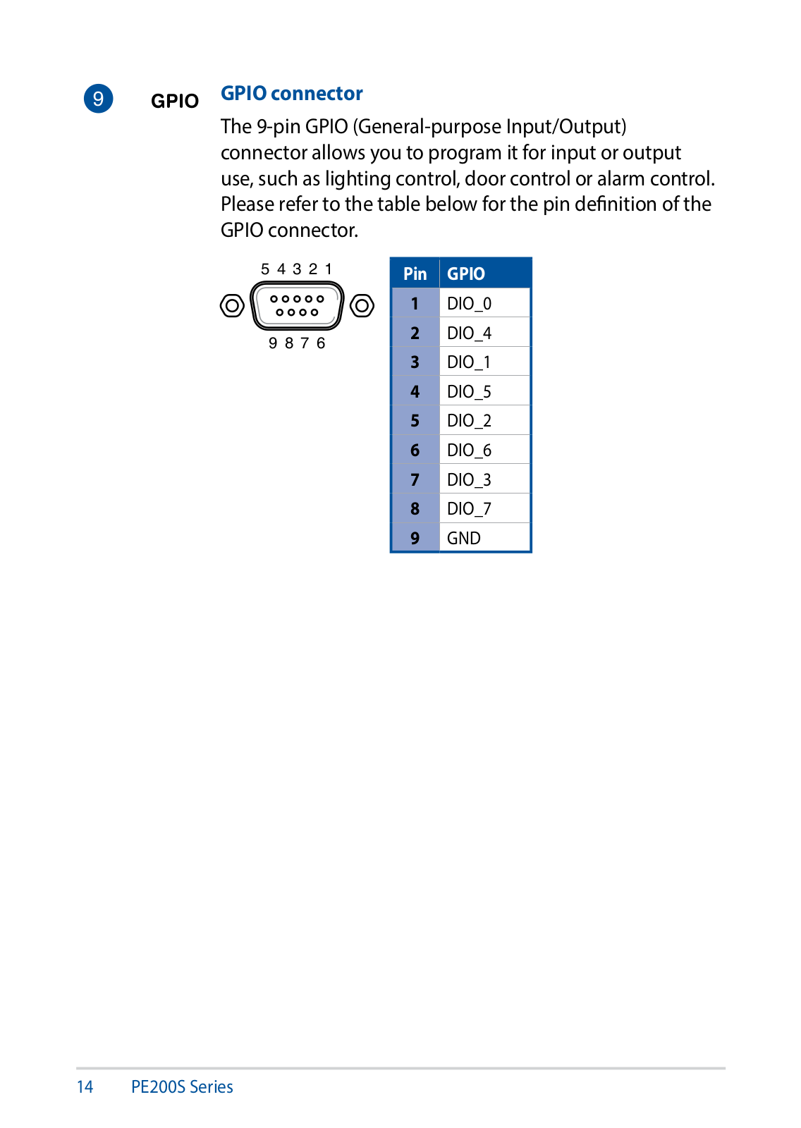
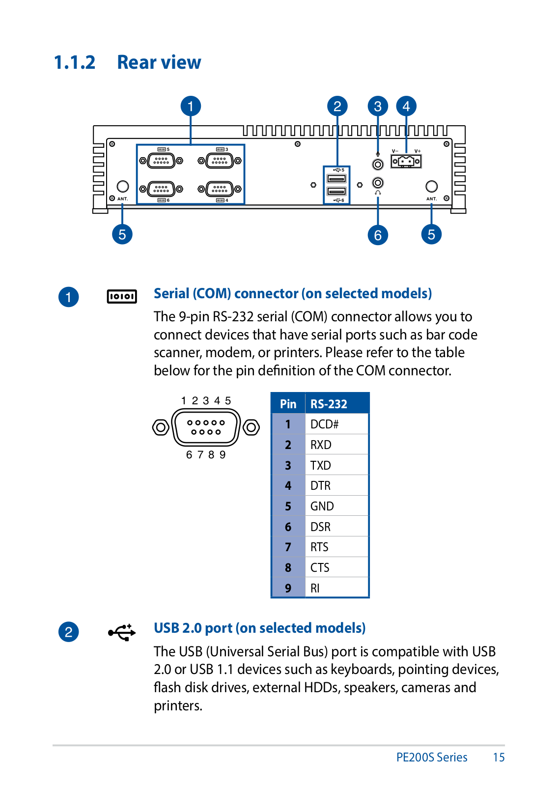
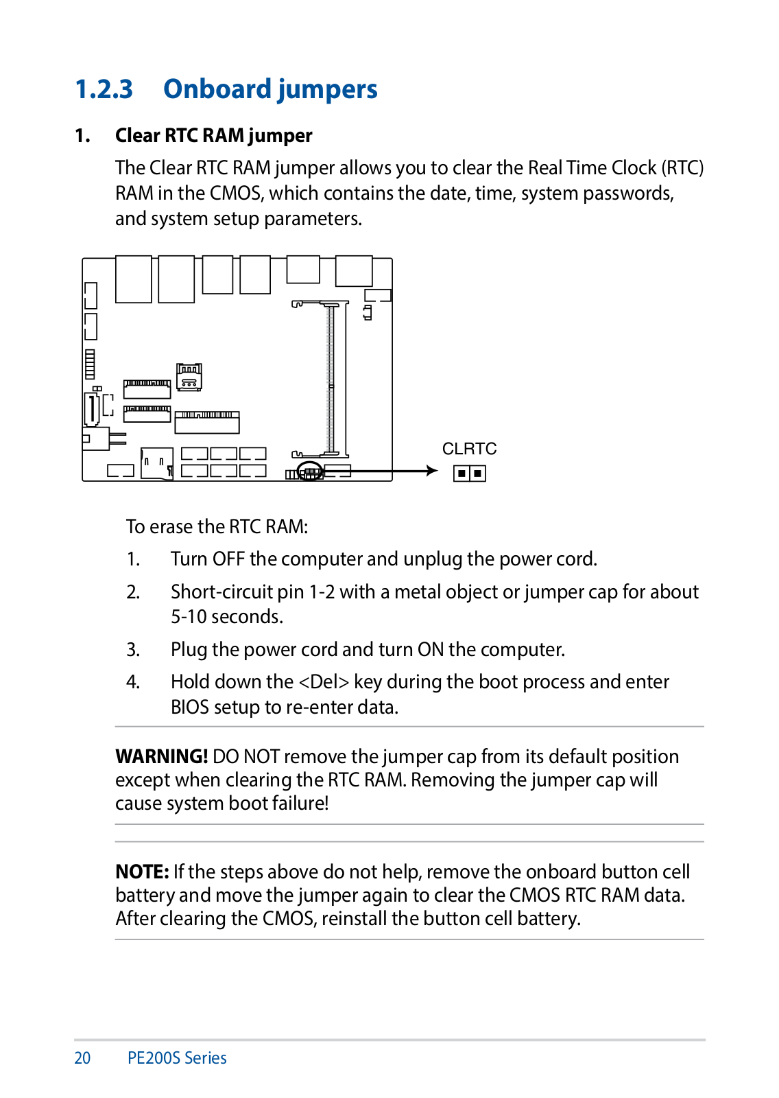
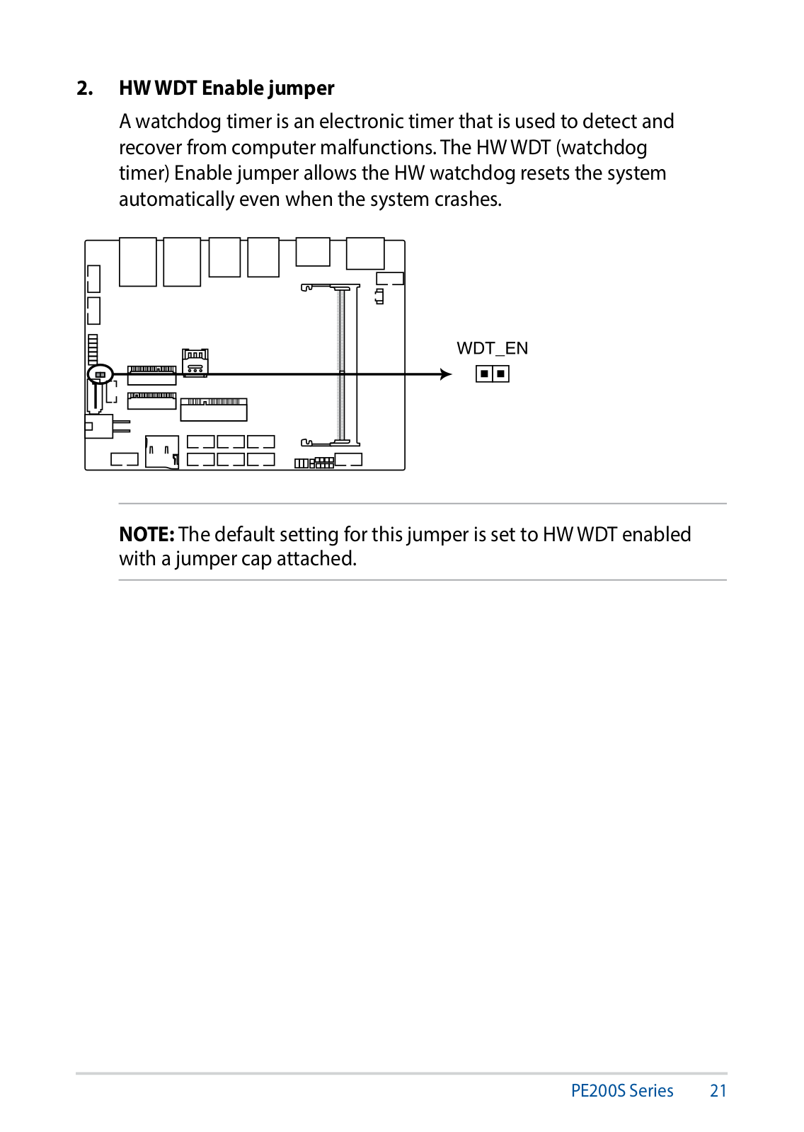
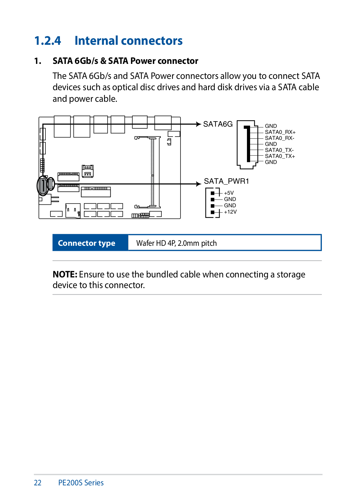
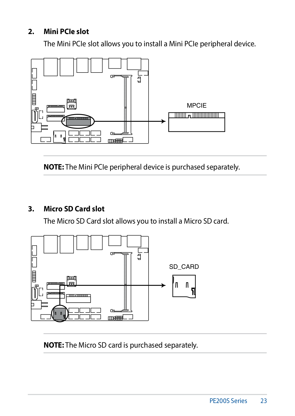
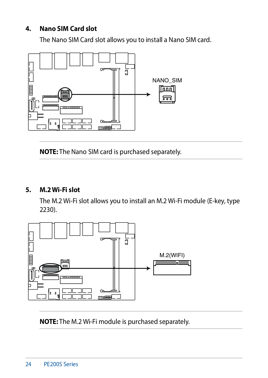
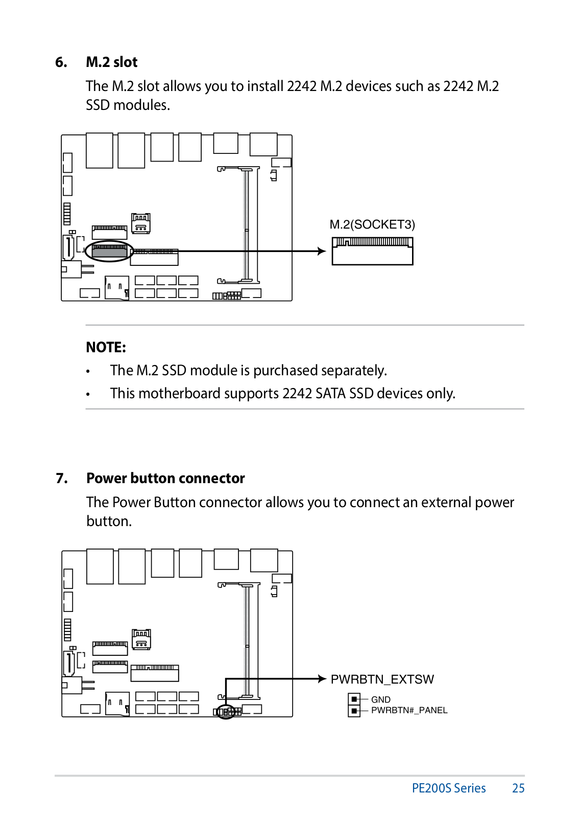
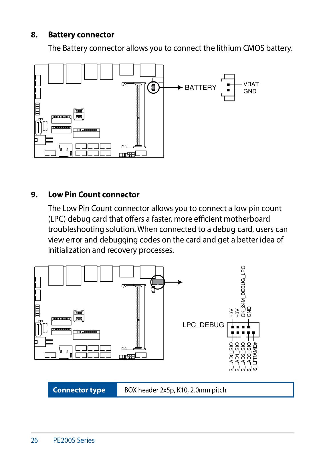
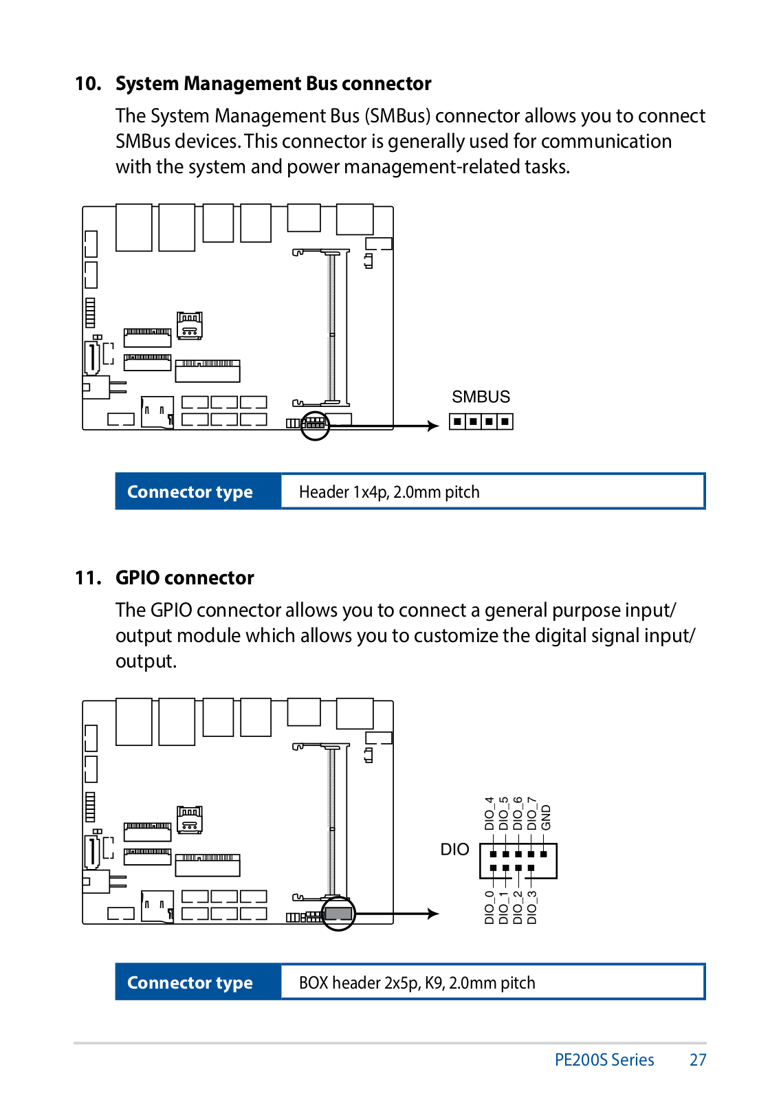
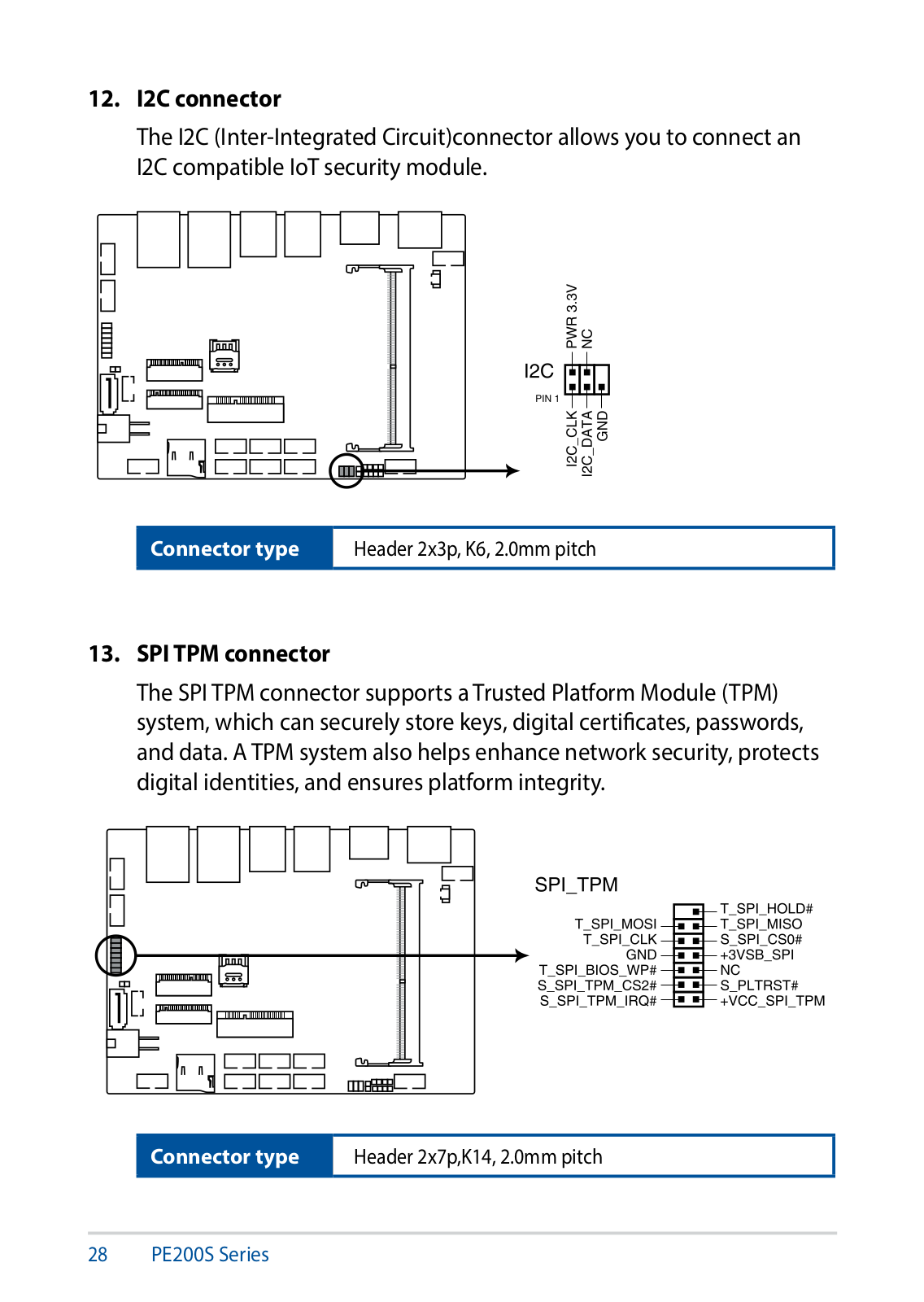
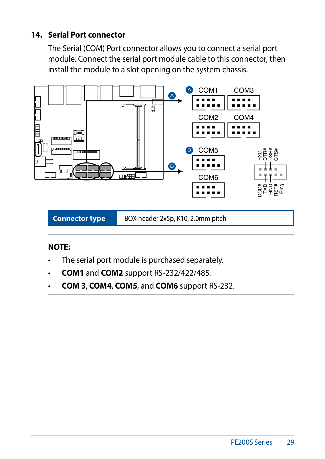
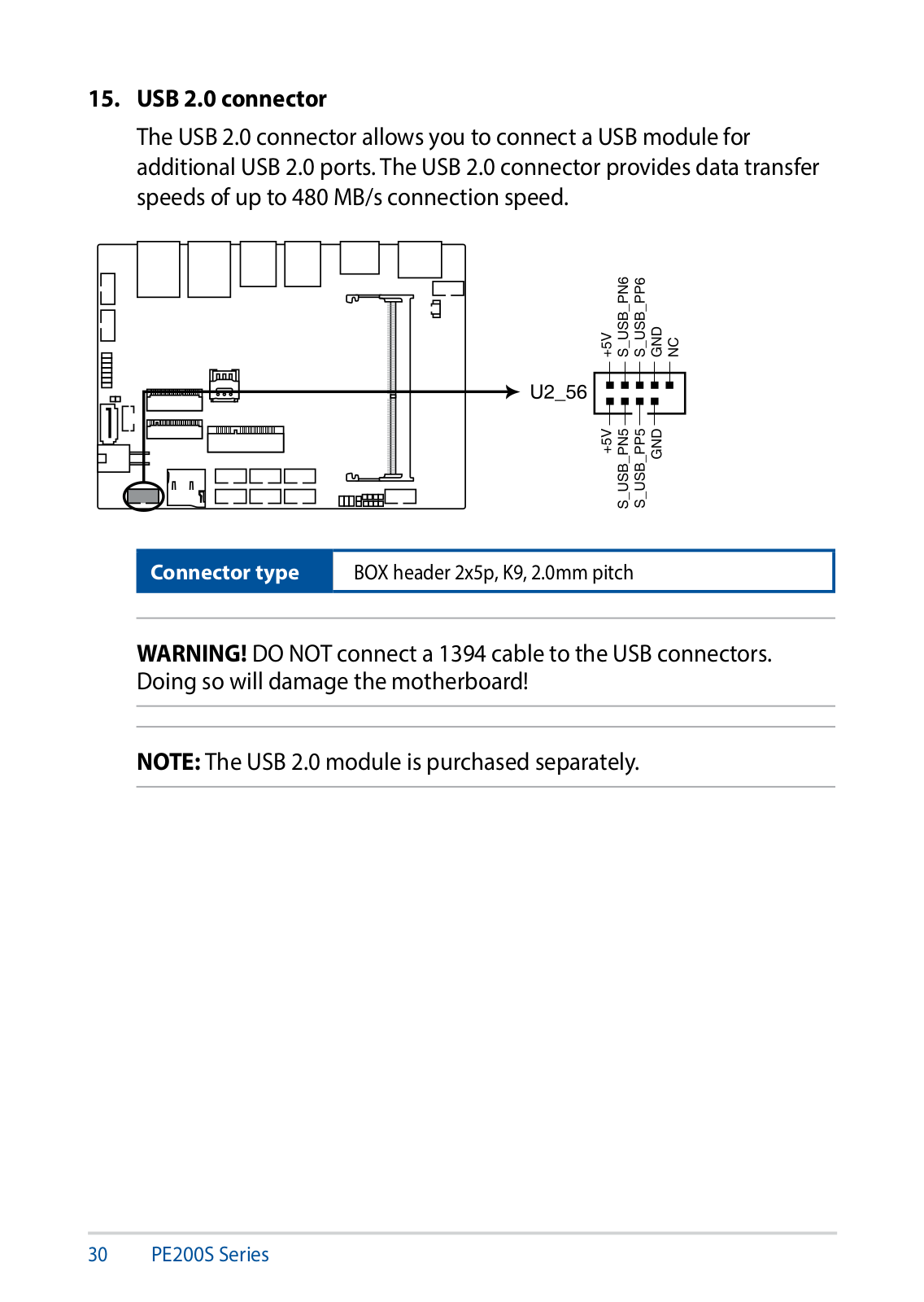
PE200S
4
PE200U
4
PE552L
PE552S
PE6300Hybrid
PE9400 Combo
PEB-10G
PEB-10G/57811-1S
2
PEB-10G/57840-2S
2
PEB-10G/57840-2T
2
PEB-10G/SFP PLUS/DUAL
PEB-10G/SFP PLUS/SINGLE
PEB-G21
2
Pedestal Server TS100-E4/PI2
PEI-10G/82599-2S
2
PEM-FDR
12
PE-P55T2P4D
PF400CG
2
PF451CL
2
PF500KL
6
PFQ3
PG10029
PG191
13
PG221
10
PG221H
8
PG221U
PG221W
PG248Q
18
PG258Q
25
PG259QN
25
PG259QNR
26
PG278Q
14
PG278QE
22
PG278QR
11
PG279
PG279Q
16
PG279QE
26
PG279QR
26
PG279QZ
15
PG27AQ
14
PG27UQ
26
PG27VQ
25
PG3098
PG329Q
26
PG348
PG348Q
18
PG348QR
PG349Q
26
PG35VQ
24
PG43UQ
26
PG4499
Loading...
Loading...
Nothing found
PE200S
Datasheet
2 pgs
666.92 Kb
0
User’s Manual
126 pgs
12.27 Mb
0
User’s Manual
118 pgs
12 Mb
0
User’s Manual
116 pgs
11.84 Mb
0
Table of contents
Loading...
Asus PE200S User’s Manual
...
Asus User’s Manual
Download
Specifications and Main Features
Frequently Asked Questions
User Manual
Download
Loading...
+
86
hidden pages
Unhide
You need points to download manuals.
1 point = 1 manual.
You can buy points or you can get point for every manual you upload.
Buy points
Upload your manuals
 Loading...