

Page 1

R
PCI-V775V2
PCI Graphics Adapter
USER'S MANUAL
Page 2

USER'S NOTICE
No part of this product, including the product and software may be reproduced,
transmitted, transcribed, stored in a retrieval system, or translated into any language in any form by any means without the express written permission of ASUST eK
COMPUTER INC. (hereinafter referred to as ASUS) except documentation kept
by the purchaser for backup purposes.
ASUS provides this manual "as is" without warranty of any kind, either express or
implied, including but not limited to the implied warranties or conditions of merchantability or fitness for a particular purpose. In no event shall ASUS be liable for
any loss or profits, loss of business, loss of use or data, interruption of business, or
for indirect, special, incidental, or consequential damages of any kind, even if ASUS
has been advised of the possibility of such damages arising from any defect or error
in this manual or product. ASUS may revise this manual from time to time without
notice.
Products mentioned in this manual are mentioned for identification purposes only.
Product names appearing in this manual may or may not be registered trademarks
or copyrights of their respective companies.
The product name and revision number are both printed on the board itself. Manual
revisions are released for each board design represented by the digit before and
after the period of the manual revision number . Manual updates are represented by
the third digit in the manual revision number . For updated BIOS, drivers, or product release information you may visit ASUS' home page at: http://www .asus.com.tw/
© Copyright 1996 ASUSTeK COMPUTER INC. All rights reserved.
Product Name: ASUS PCI-V775V2
Manual Revision: 1.02
Release Date: January 1997
II
ASUS PCI-V775V2 User's Manual
Page 3

ASUS CONTACT INFORMATION
ASUSTeK COMPUTER INC.
Marketing Info:
Address: 150 Li-Te Road, Peitou, Taipei, Taiwan, ROC
Telephone: 886-2-894-3447
Fax: 886-2-894-3449
Email: info@asus.com.tw
Technical Support:
Fax: 886-2-895-9254
BBS: 886-2-896-4667
Email: tsd@asus.com.tw
WWW: http://www.asus.com.tw/
Gopher: gopher.asus.com.tw
FTP: ftp.asus.com.tw/pub/ASUS
ASUS COMPUTER INTERNATIONAL
Marketing Info:
Address: 721 Charcot Avenue, San Jose, CA 95131, USA
Telephone: 1-408-474-0567
Fax: 1-408-474-0568
Email: info-usa@asus.com.tw
Technical Support:
BBS: 1-408-474-0555
Email: tsd-usa@asus.com.tw
ASUS COMPUTER GmbH
Marketing Info:
Address: Harkort Str. 25, 40880 Ratingen, BRD, Germany
Telephone: 49-2102-445011
Fax: 49-2102-442066
Email: info-ger@asus.com.tw
Technical Support:
BBS: 49-2102-448690
Email: tsd-ger@asus.com.tw
ASUS PCI-V775V2 User's Manual III
Page 4

CONTENTS
I. Hardware Installation..................................................1
Layout of the ASUS PCI-V775V2 Card........................1
Installation Procedures...................................................2
II. Microsoft Windows 95................................................4
Video Driver Installation ...............................................4
Introduction....................................................................4
New Hardware Found ...............................................4
Using Autorun Screen ...............................................5
Using Windows 95 Control Panel .............................6
Software MPEG & Video Player ...................................7
Installing DirectX and MPEG Movie Player in Win95 .7
Windows 95 Display Settings ........................................8
Adjustment: ...............................................................8
Change Refresh Rate ............................................8
Adjust Performance..............................................9
Hotkey:......................................................................9
Settings:.....................................................................9
III. Microsoft Windows 3.x ...........................................10
Video Driver Installation .............................................10
Installing Video drivers in DOS ..............................10
Installing Video drivers in Windows 3.x .................10
Software MPEG & Video Player .................................11
Installing VFW and MPEG Movie Player in Win3.x .. 11
IV
ASUS PCI-V775V2 User's Manual
Page 5

CONTENTS
Windows 3.x Display Panel .........................................12
Settings:...................................................................12
Tune Performance ..............................................12
Adjustment: .............................................................13
Change Refresh Rate ..........................................13
Hotkey:....................................................................14
DPMS:.....................................................................14
IV. Microsoft Windows NT ...........................................15
Video Driver Installation .............................................15
Installing Display Drivers for Windows NT 4.0 .....15
Installing Display Drivers in Windows NT 3.51.....16
V. IBM OS/2 Video Driver ............................................17
IBM OS/2 Video Driver Installation............................17
VI. Other Video Drivers ................................................18
AutoCAD Video Driver Installation ............................18
Microstation Video Driver Installation ........................18
VII. Display Information ..............................................19
Resolution Table ..........................................................19
1 MB Video Memory ..............................................19
2 MB Video Memory ..............................................20
4 MB Video Memory ..............................................23
VIII. Hardware Information ........................................24
8-bit LPB Connector....................................................24
16-bit LPB Connector..................................................25
A. Questions & Answers................................................26
ASUS PCI-V775V2 User's Manual V
Page 6

FCC & DOC COMPLIANCE
Federal Communications Commission Statement
This device complies with FCC Rules Part 15. Operation is subject to the following
two conditions:
• This device may not cause harmful interference, and
• This device must accept any interference received, including interference that
may cause undesired operation.
This equipment has been tested and found to comply with the limits for a Class B
digital device, pursuant to Part 15 of the FCC Rules. These limits are designed to
provide reasonable protection against harmful interference in a residential installation. This equipment generates, uses and can radiate radio frequency energy and, if
not installed and used in accordance with manufacturer's instructions, may cause
harmful interference to radio communications. However, there is no guarantee that
interference will not occur in a particular installation. If this equipment does cause
harmful interference to radio or television reception, which can be determined by
turning the equipment off and on, the user is encouraged to try to correct the interference by one or more of the following measures:
• Re-orient or relocate the receiving antenna.
• Increase the separation between the equipment and receiver.
• Connect the equipment to an outlet on a circuit different from that to which
the receiver is connected.
• Consult the dealer or an experienced radio/TV technician for help.
WARNING: The use of shielded cables for connection of the monitor to the graphics
card is required to assure compliance with FCC regulations. Changes or modifications to this unit not expressly approved by the party responsible for compliance
could void the user's authority to operate this equipment.
Canadian Department of Communications Statement
This digital apparatus does not exceed the Class B limits for radio noise emissions
from digital apparatus set out in the Radio Interference Regulations of the Canadian Department of Communications.
VI
ASUS PCI-V775V2 User's Manual
Page 7
I. Hardware Installation
Thank you for purchasing the ASUS PCI-V775V2 Graphics
Adapter, the latest S3 Trio64V2/DX Graphics Engine which
provides the best video quality in any scale.
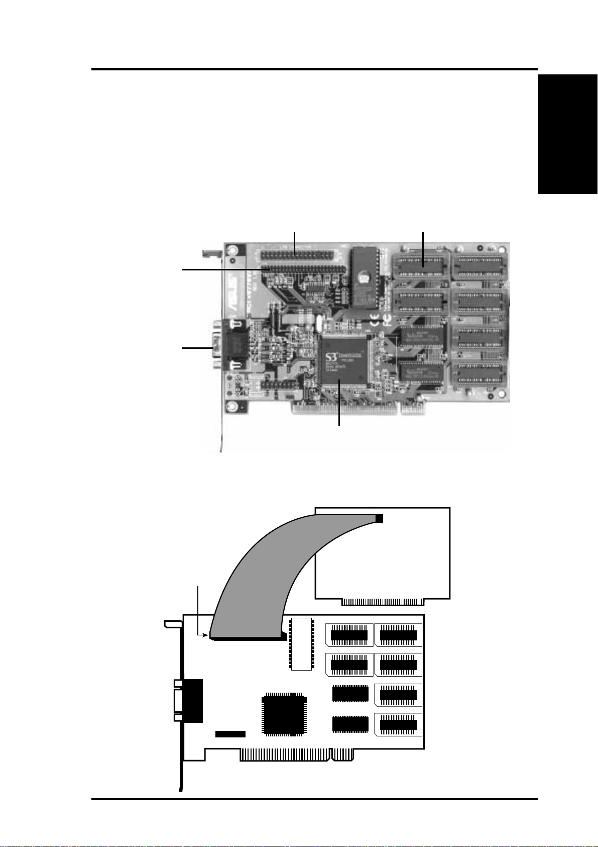
Layout
Layout of the ASUS PCI-V775V2 Card
8-BIT LPB Connector
& Feature Connector
16-BIT LPB
Connector
Video Output
Connector
S3 Trio64V2/DX Chipset
1 MB Video memory is standard. Add two 512KB RAMs to
1-4 MB Memory
I. H/W Installation
upgrade this to 2MB, four for 3 MB, or six for 4 MB.
Optional LPB adapters:
TV Tuners, MPEG,
Video Capture Cards
LPB Connector
ASUS PCI-V775V2 User’s Manual 1
Page 8

I. Hardware Installation
I. H/W Installation
This section tells you how to install the ASUS PCI-V775V2
Procedures
Video Card in your PC computer. The steps provided below
demonstrate how to install the cards in a typical system. Your
system may be slightly different.
WARNING: Computer boards and components contain
very delicate Integrated Circuit (IC) chips. To protect the
computer board and other components against damage from
static electricity , you should follow some precautions whenever you work on your computer.
1. Make sure that you unplug your power supply when adding or removing expansion cards or other system components. Failure to do so may cause severe damage to
both your motherboard and expansion cards.
2. Hold components by the edges and try not to touch the
IC chips, leads, or circuitry.
3. Use a grounded wrist strap before handling computer
components.
4. Place components on a grounded antistatic pad or on the
bag that came with the component whenever the components are separated from the system.
IMPORTANT: Keep the host adapter in its antistatic bag
until you are ready to install it. Before you pick up the
adapter, ground yourself by touching an unpainted surface
on the computer chassis. Even a little static electricity can
destroy a host adapter component!
Installation Procedures
1. Unplug all electrical cords on your computer.
2. Remove the screws for the back of the system unit cover.
3. Remove the system unit cover.
4. Find an unused 5volt PCI bus expansion slot. Make sure
this slot is unobstructed.
2 ASUS PCI-V775V2 User’s Manual
Page 9
I. Hardware Installation
5. Remove the corresponding expansion slot cover from the
computer chassis. The slot cover is the metal strip in the
back of the computer chassis that covers the opening for the
adapter’s external connector.
6. Ground yourself to an antistatic mat or other grounded source.
7. Pick up the board (still in its sleeve) by grasping the edge
bracket with one hand. Avoiding touching board components.
8. Remove the plastic sleeve.
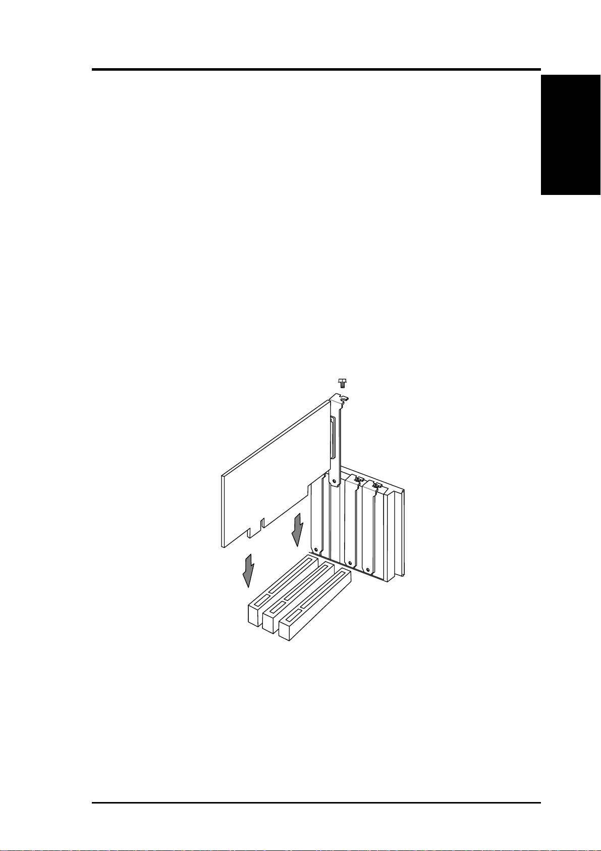
9. Position the card directly over the PCI slot and insert one
end of the board in the slot first. Carefully press the bus
connector on the bottom of the card down into the slot. Be
sure the metal contacts on the bottom of the host adapter are
securely seated in the slot.
Procedures
I. H/W Installation
10.Anchor the board's mounting bracket to the computer chas-
sis using the screw from the slot cover you set aside previously.
11.Replace the cover on the system unit.
12.Connect your analog monitor's 15-pin VGA connector to
the card and fasten the retaining screws (if any).
ASUS PCI-V775V2 User’s Manual 3
Page 10
II. Microsoft Windows 95
Video Driver Installation
Introduction
After installing the ASUS PCI-V775V2 Video card, software
drivers and utilities must be installed. The following are vari-
Driver Installation
II. Windows 95
ous driver installation procedures for Windows 95 under specific situations.
Installing Video drivers in Windows 95 (New Hardware
Found)
If you are installing the ASUS PCI-V775V2 Video card for
Windows 95 for the first time, a New Hardware Found win-
dow will appear:
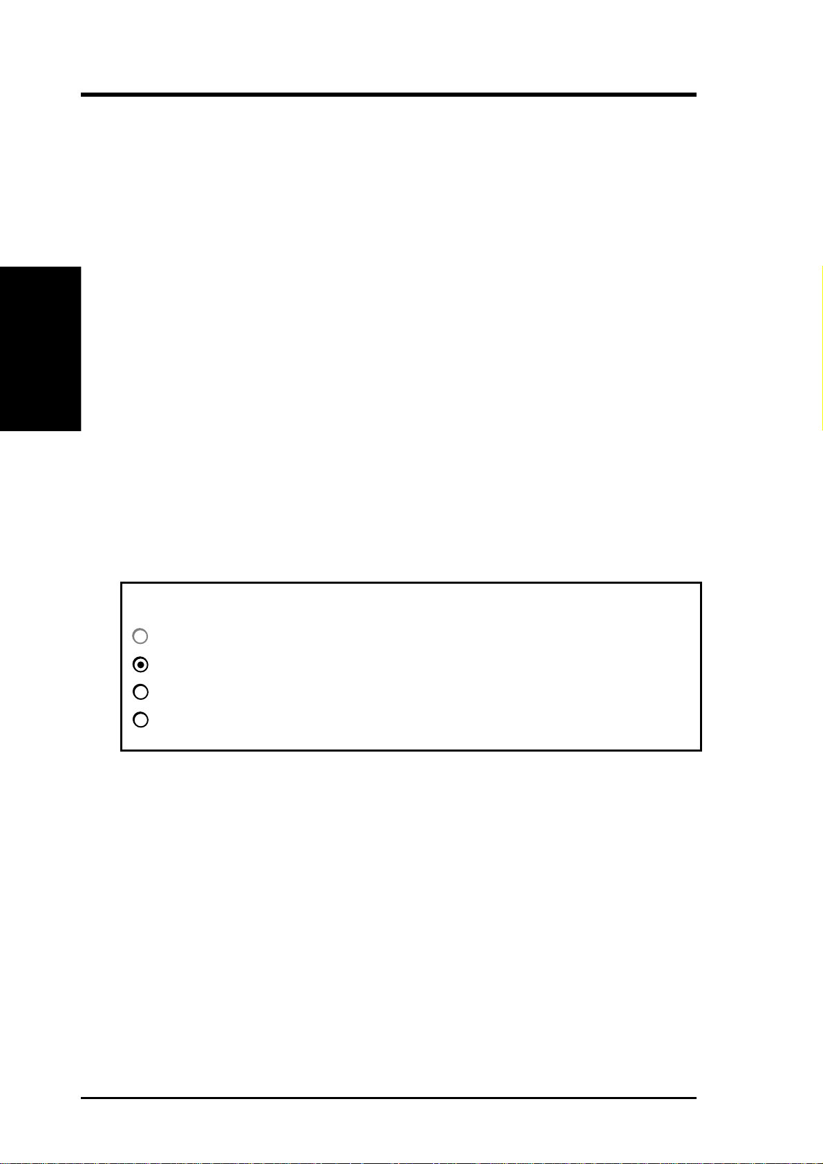
Select which driver you want to install for your new hardware:
Windows default driver
Driver from disk provided by hardware manufacturer
Do not install a driver (W indows will not prompt you again)
Select from a list of alternate drivers
1. Click OK to use the default selection: Driver from disk
provided by hardware manufacturer
2. Insert ASUS installation CD and click Browse button - Open
window appears
3. Select your CD-ROM drive in the Drives: box
4. Select win95
5. Click the OK button - Install from Disk appears - Click OK
button again
6. After restarting Windows, your ASUS card should be automatically detected.
4 ASUS PCI-V775V2 User’s Manual
Page 11

II. Microsoft Windows 95
Video Driver Installation
Updating installation in Windows 95 (Using Autorun Screen)
If an ASUS Video card was installed at one time, Windows 95
Plug and Play may install the original driver upon entering
Windows 95. The driver of previous version may cause your
system to hang. If this happens, switch to the standard VGA
mode (640 x 480 x 16 colors), then restart W indows 95. Insert
the ASUS PCI-V775V2 installation CD. ASUS Windows 95
Install Shell will appear:
II. Windows 95
Driver Installation
If Windows 95 Install Shell does not appear, select
D:\AUTORUN.EXE. The CD-ROM’s autorun facility will
present you with a list of install options. Click Install Win-
dows 95 Display Driver and follow the installation steps.
ASUS PCI-V775V2 User’s Manual 5
Page 12

Video Driver Installation
Installing ASUS PCI-V775V2 V ideo drivers in Windows 95
(Using Windows 95 Control Panel)
Driver Installation
II. Windows 95
1. Start Windows 95, switch display to VGA mode, then restart.
2. Press right key of mouse on your desktop and select Prop-
erties. Click the Settings tab.
II. Microsoft Windows 95
3. Select Change Display Type.
4. Click Change..
5. Click Have Disk. Insert the ASUS PCI-V775V2 installa-
tion CD. Type D:\WIN95 (assuming your CD-ROM drive
is letter D) or click Browse button to select path of display
driver for Windows 95. Click OK. You will see a list of
ASUS S3 cards. Select type of your VGA card and press
OK to start installation.
6. When all files are copied, back to Display Properties window by clicking Close. Press Apply.. Click Yes to restart
Windows.
7. When Windows starts up, your video adapter is now ready
to use.
6 ASUS PCI-V775V2 User’s Manual
Page 13

II. Microsoft Windows 95
Software MPEG & Video Player
For Software MPEG support in Windows 95, you must first
install Microsoft DirectX libraries, then install ASUS MPEG
Movie Player.
Installing Microsoft DirectX and MPEG Movie Player in
Windows 95
Start Windows 95. Insert the ASUS PCI-V775V2 installation
CD. ASUS Windows 95 Install Shell should appear. If Windows 95 Install Shell does not appear, select
D:\AUTORUN.EXE. The CD-ROM’s autorun facility will
present you with a list of install options.
If you have installed DirectX, simply click Install Video Player.
Otherwise, click Install DirectX first.
II. Windows 95
Driver Installation
When driver has successfully been installed, click Install Video
Player and follow the installation steps.
ASUS PCI-V775V2 User’s Manual 7
Page 14

II. Microsoft Windows 95
Windows 95 Display Settings
Changing display settings
To enter the Display Properties at any time, right click your
Display Settings
II. Windows 95
mouse on the desktop and select Properties or double click the
Display icon in the Control Panel. Click the appropriate Tab
as follows:
Adjustment:
Lets you change your
monitor settings,
such as position, size,
refresh rate and performance.
Adjust
display size
Adjust
display position
Change Refresh Rate
List of refresh
rate options
Customize
refresh rate
Test customized
refresh rates
Add to list
8 ASUS PCI-V775V2 User’s Manual
Delete from list
Page 15

II. Microsoft Windows 95
Adjust Performance
Hotkey:
Allows you to assign
hotkeys in the "Value"
box to move your
screen up, down, left,
and right, or zoom in,
zoom out in virtual
Maximum
performance
II. Windows 95
Display Settings
desktop.
List of hotkey
options
Hotkey
enabled
Settings:
Allows you to change
your display settings,
adjust screen resolution and color depth,
virtual desktop, color
palette and font size.
Adjust
screen
resolution
Adjust color
Adjust
font size
ASUS PCI-V775V2 User’s Manual 9
Adjust
virtual
desktop
size
Page 16

Video Driver Installation
The ASUS PCI-V775V2 V ideo drivers for W indows 3.x can be
installed in Windows 3.x or in DOS.
Installing ASUS PCI-V775V2 Video drivers in DOS
Insert the ASUS PCI-V775V2 Video card. Start your computer. T ype D:\W31INST in DOS mode. Input path where
your Windows 3.x system is located.
Driver Installation
III. Windows 3.x
III. Microsoft Windows 3.x
When ASUS driver is successfully installed, you can launch
Windows 3.x by pressing Y key if PCI-V775V2 V ideo card has
been plugged in your system. After W indows 3.x boots up, the
CD-ROM’s autorun facility will present you with a list of install options. You can continue to install the other applications.
Installing ASUS PCI-V775V2 Video drivers in Windows 3.x
Insert the ASUS PCI-V775V2 Video card. Restart your computer. Enter DOS mode. Switch to the standard VGA mode,
then start Windows 3.x and double click autorun.exe. The
CD-ROM’s autorun facility will present you with a list of install options. Click on Install Windows 3.x Display Driver
and follow the installation steps.
10 ASUS PCI-V775V2 User’s Manual
Page 17

III. Microsoft Windows 3.x
Software MPEG & Video Player
For Software MPEG support in Windows 3.X, you must first
install Microsoft V ideo for W indows, then install ASUS MPEG
Movie Player.
Installing Microsoft Video for W indows and MPEG Movie
Player in Windows 3.x
1. Start Windows 3.x
2. Insert the ASUS installation CD
3. Double click autorun.exe
4. The CD-ROM’s autorun facility will present you with a
list of install options
5. Click on Install Video for Windows if you have not in-
stalled V ideo for Windows
III. Windows 3.x
Driver Installation
6. Click on Install Video Player and follow the installation
steps.
ASUS PCI-V775V2 User’s Manual 11
Page 18

Windows 3.x Display Panel
Changing display settings
To enter the ASUS Display Panel, open ASUS S3 Series program group and click ASUS Display Panel icon. Click the
appropriate Tab as follows:
Settings:
Allows you to adjust screen resolution, virtual desktop size,
color palette, font size, and change performance.
III. Windows 3.x
Display Panel
III. Microsoft Windows 3.x
Adjust color
Adjust
font size
Tune Performance
Maximum
performance
Adjust
performance
Adjust
screen
resolution
Adjust virtual
desktop size
Adjust
performance
12 ASUS PCI-V775V2 User’s Manual
Page 19

III. Microsoft Windows 3.x
Windows 3.x Display Panel
Adjustment:
Lets you change your monitor settings, such as display position, size and refresh rate.
Adjust
display size
Adjust
display position
Set to
default values
Change Refresh Rate
List of refresh
rate options
Change refresh rate
Display Panel
III. Windows 3.x
Customize
refresh rate
ASUS PCI-V775V2 User’s Manual 13
Add to list
Test customized
refresh rates
Delete from list
Page 20

III. Microsoft Windows 3.x
Hotkey:
Allows you to assign hotkeys in the "Value" box to move your
virtual screen up, down, left, and right, or zoom in, zoom out,
or lock the screen in virtual desktop.
III. Windows 3.x
Display Panel
DPMS:
Let you configure the time of Standby , Suspend, and PowerOff
mode for your DPMS-compliant monitor to conserve electrical
energy .
List of
hotkey
options
Hotkey
enabled
Value
Description
DPMS
enabled
14 ASUS PCI-V775V2 User’s Manual
Set to
default
values
Page 21

IV. Microsoft Windows NT
Video Driver Installation
Installing ASUS S3 series Display Drivers for Windows NT 4.0
After installing your graphics card, Windows NT will default
to standard VGA mode (640 x 480, 16 colors). The procedure
below describes how you install ASUS S3 series display driver
for W indows NT.
1. Boot W indows NT in standard VGA mode (recommended).
Run Windows NT Display program located in the Control
Panel, under Settings in the Start menu. Alternatively, position the cursor on the background of the desktop, click
the right mouse button, then select Properties from the
popup menu.
2. Select the Settings page.
3. Select Display Type...
4. Select Change... from the display options.
5. Select Have Disk...
6. NT will prompt you for the correct path, enter the path of
driver in CD-ROM such as D:\NT40 (assuming your CDROM drive is letter D).
7. A list of ASUS S3 series video adapters will be displayed.
Select the one you are using, then click on the OK button.
8. W indows NT will once again prompt for confirmation. All
IV. Windows NT
Driver Installation
appropriate files are then copied to the hard disk.
9. Select Apply in Control Panel. Restart Windows NT. W in-
dows NT will start up using the S3 drivers.
10. NT will boot into a default mode and start the Display applet
allowing for mode selection.
ASUS PCI-V775V2 User’s Manual 15
Page 22

IV. Microsoft Windows NT
Video Driver Installation
Installing ASUS
NT 3.51
After installing your graphics card, Windows NT will default
to standard VGA mode (640 x 480, 16 colors). The procedure
below describes how you install ASUS S3 series display driver
for W indows NT.
1. Boot W indows NT in standard VGA mode (recommended).
2. Double-click the Main icon.
3. Double-click the Control Panel icon.
4. Double-click the Display icon.
5. Click Change Display Type.
6. Click Change.
S3 series
Video
Display
Drivers in Windows
Driver Installation
IV. Windows NT
7. Click Other.
8. Insert the ASUS S3 driver CD into your CD-ROM drive.
9. Click OK.
10. Select S3 driver.
11. Click Install.
12. Click Yes to change your system configuration.
13. Click Continue to confirm the full path name.
14. After the files have been copied to your computer, click
15. Reboot Windows NT. After reboot, the Invalid Display
For W indows NT 3.51, type the following: D:\NT351 (assuming your CD-ROM drive is letter D)
OK.
Settings window appears.
16. Click OK. The Display Settings dialogue box appears.
17. Select a desired display mode. For more detailed informa-
tion about changing your display mode, click Help.
16 ASUS PCI-V775V2 User’s Manual
Page 23

V. IBM OS/2 Video Driver
IBM OS/2 Video Driver Installation
The ASUS PCI-V775V2 OS/2 video driver is to be used for
the English version of OS/2 only.
Installing ASUS PCI-V775V2 video drivers in English OS/2
1. Start OS/2 using standard VGA driver
2. Shut down OS/2. Insert the ASUS PCI-V775V2 Video
card. Restart OS/2.
3. Double-click the OS/2 System folder
4. Double-click the Command Prompts folder
5. Double-click the OS/2 Full Screen object
6. Insert the ASUS installation CD (assuming your CD-ROM
drive is letter D)
7. Type D:\OS2 <Enter>, SETUP.CMD <Enter>
8. In the Monitor Configuration Selection Utility, select In-
stall Using Defaults for Monitor Type
9. Click OK when Display Driver Install panel appears
10. Restart OS/2. It will default to 640x480 in 256 colors. T o
change screen resolution and/or color depth, see your OS/
2 User’s Guide.
V. IBM OS/2
Driver Installation
ASUS PCI-V775V2 User’s Manual 17
Page 24

AutoCAD/Microstation
VI. Other Drivers
AutoCAD Video Driver Installation
Installing ASUS PCI-V775V2 AutoCAD Video Drivers
1. Enter DOS mode
2. Insert the ASUS installation CD (assuming your CD-ROM
drive is letter D)
3. Change current directory to D:\DOS\AutoCAD, type IN-
STALL <Enter>
4. Follow the instructions to complete the installation of the
drivers. Type directory name where AutoCAD drivers are
located when installation program asks you. Your video
VI. Other Video Drivers
drivers should be installed and ready to use.
Microstation Video Driver Installation
Installing ASUS PCI-V775V2 Microstation Video Drivers
1. Enter DOS mode
2. Insert the ASUS installation CD (assuming your CD-ROM
drive is letter D)
3. Change current directory to D:\DOS\Mstation, type IN-
STALL <Enter>
4. Follow the instructions to complete the installation of the
drivers. Your video drivers should be installed and ready
to use.
18 ASUS PCI-V775V2 User’s Manual
Page 25

VII. Display Information
Resolution Table
1 MB Video Memory
Resolution & Vertical Horizontal Note
Color Depth Frequency Frequency
640x480x8 60Hz 31.3KHz
72Hz 38.0KHz
75Hz 37.6KHz
85Hz 43.5KHz
100Hz 50.9KHz
160Hz 81.9KHz
800x600x8 60Hz 37.9KHz
72Hz 48.3KHz
75Hz 46.9KHz
85Hz 53.5KHz
100Hz 62.9KHz
150Hz 94.8KHz
Resolution Table
VII. Display Info
1024x768x8 int. 35.4KHz
60Hz 49.8KHz
70Hz 56.6KHz
75Hz 60.0KHz
85Hz 69.0KHz
100Hz 80.8KHz
120Hz 96.7KHz
1152x864x8 60Hz 54.9KHz Win31 Only
72Hz 66.4KHz Win31 Only
75Hz 70.1KHz Win31 Only
85Hz 80.3KHz Win31 Only
100Hz 96.7KHz Win31 Only
640x480x16 60Hz 31.3KHz
72Hz 38.0KHz
75Hz 37.6KHz
85Hz 43.5KHz
100Hz 50.9KHz
160Hz 82.0KHz
800x600x16 60Hz 37.9KHz
72Hz 48.3KHz
75Hz 46.9KHz
85Hz 53.5KHz
100Hz 62.9KHz
150Hz 94.8KHz
640x480x24 60Hz 31.3KHz Win31 Only
640x400x32 70Hz 31.3KHz Win95 Only
int. = Interlace
ASUS PCI-V775V2 User’s Manual 19
Page 26

2 MB Video Memory
VII. Display Info
Resolution Table
VII. Display Information
Resolution & Vertical Horizontal Note
Color Depth Frequency Frequency
640x480x8 60Hz 31.3KHz
72Hz 38.0KHz
75Hz 37.6KHz
85Hz 43.5KHz
100Hz 50.9KHz
160Hz 81.9KHz
800x600x8 60Hz 37.9KHz
72Hz 48.3KHz
75Hz 46.9KHz
85Hz 53.5KHz
100Hz 62.9KHz
150Hz 94.8KHz
1024x768x8 int. 35.4KHz
60Hz 49.8KHz
70Hz 56.6KHz
75Hz 60.0KHz
85Hz 69.0KHz
100Hz 80.8KHz
120Hz 96.7KHz
1152x864x8 60Hz 54.9KHz
72Hz 66.4KHz
75Hz 70.1KHz
85Hz 80.3KHz
100Hz 96.7KHz
1280x1024x8 int. 46.5KHz
60Hz 64.2KHz
72Hz 76.8KHz
75Hz 79.9KHz
85Hz 90.4KHz
1600x1200x8 int. 63.8KHz
60Hz 75.6KHz
72Hz 90.4KHz
75Hz 94.2KHz
int. = Interlace
20 ASUS PCI-V775V2 User’s Manual
Page 27

VII. Display Information
640x480x16 60Hz 31.3KHz
72Hz 38.0KHz
75Hz 37.6KHz
85Hz 43.5KHz
100Hz 50.9KHz
160Hz 82.0KHz
800x600x16 60Hz 37.9KHz
72Hz 48.3KHz
75Hz 46.9KHz
85Hz 53.5KHz
100Hz 62.9KHz
150Hz 94.8KHz
1024x768x16 int. 35.4KHz
60Hz 49.6KHz
70Hz 56.6KHz
75Hz 60.0KHz
85Hz 69.0KHz
100Hz 80.8KHz
120Hz 96.7KHz
640x480x24 60Hz 31.3KHz Win31 Only
640x400x32 70Hz 31.3KHz Win95 Only
640x480x32 60Hz 31.3KHz
72Hz 38.0KHz
75Hz 37.6KHz
85Hz 43.5KHz
100Hz 50.9KHz
160Hz 81.4KHz
800x600x32 60Hz 37.9KHz
72Hz 48.3KHz
75Hz 46.9KHz
85Hz 53.5KHz
100Hz 62.9KHz
150Hz 94.8KHz
Resolution Table
VII. Display Info
int. = Interlace
ASUS PCI-V775V2 User’s Manual 21
Page 28

4 MB Video Memory
VII. Display Info
Resolution Table
VII. Display Information
Resolution & Vertical Horizontal Note
Color Depth Frequency Frequency
640x480x8 60Hz 31.3KHz
72Hz 38.0KHz
75Hz 37.6KHz
85Hz 43.5KHz
100Hz 50.9KHz
160Hz 81.9KHz
800x600x8 60Hz 37.9KHz
72Hz 48.3KHz
75Hz 46.9KHz
85Hz 53.5KHz
100Hz 62.9KHz
150Hz 94.8KHz
1024x768x8 int. 35.4KHz
60Hz 49.8KHz
70Hz 56.6KHz
75Hz 60.0KHz
85Hz 69.0KHz
100Hz 80.8KHz
120Hz 96.7KHz
1152x864x8 60Hz 54.9KHz
72Hz 66.4KHz
75Hz 70.1KHz
85Hz 80.3KHz
100Hz 96.7KHz
1280x1024x8 int. 46.5KHz
60Hz 64.2KHz
72Hz 76.8KHz
75Hz 79.9KHz
85Hz 90.4KHz
1600x1200x8 int. 63.8KHz
60Hz 75.6KHz
72Hz 90.4KHz
75Hz 94.2KHz
640x480x16 60Hz 31.3KHz
72Hz 38.0KHz
75Hz 37.6KHz
85Hz 43.5KHz
100Hz 50.9KHz
160Hz 82.0KHz
22 ASUS PCI-V775V2 User’s Manual
int. = Interlace
Page 29

VII. Display Information
800x600x16 60Hz 37.9KHz
72Hz 48.3KHz
75Hz 46.9KHz
85Hz 53.5KHz
100Hz 62.9KHz
150Hz 94.8KHz
1024x768x16 int. 35.4KHz
60Hz 49.6KHz
70Hz 56.6KHz
75Hz 60.0KHz
85Hz 69.0KHz
100Hz 80.8KHz
120Hz 96.7KHz
1280x1024x16 int. 46.5KHz
60Hz 64.8KHz
72Hz 77.6KHz
75Hz 81.2KHz
85Hz 91.9KHz
Resolution Table
VII. Display Info
640x480x24 60Hz 31.3KHz Win31 Only
640x480x32 60Hz 31.3KHz
72Hz 38.0KHz
75Hz 37.6KHz
85Hz 43.5KHz
100Hz 50.9KHz
160Hz 81.4KHz
800x600x32 60Hz 37.9KHz
72Hz 48.3KHz
75Hz 46.9KHz
640x400x32 70Hz 31.3KHz Win95 Only
85Hz 53.5KHz
100Hz 62.9KHz
150Hz 94.8KHz
1024x768x32 int. 35.4KHz
60Hz 49.6KHz
70Hz 56.6KHz
75Hz 60.0KHz
85Hz 69.0KHz
int. = Interlace
ASUS PCI-V775V2 User’s Manual 23
Page 30

VIII. Hardware Information
8-bit LPB Connector
The LPB (Local Peripheral Bus) Connector is an extension of
the VESA feature connector. An additional 6-pin and 2 pin
space added to the 26-pin feature connector make a 34-pin
header. This allows the normal 26 pin cable used for feature
connector applications to be swap out for a standard 34-pin
cable to achieve LPB operation.
VIII. H/W Information
LPB Connector
2
1
34
33
J1
Pin Signal Description Pin Signal Description
1 GND 2 PA0/LPB0
3 GND 4 PA1/LPB1
5 GND 6 PA2/LPB2
7 EVIDEO/VREQ/VRDY/HS 8 PA3/LPB3
9 ESYNC/NF 10 PA4/LPB4
11 EVCLK/CREQ/CRDY/VS 12 PA5/LPB5
13 N/C 14 PA6/LPB6
15 GND 16 PA7/LPB7
17 GND 18 VCLK/LCLK
19 GND 20 BLANK/NF
21 GND 22 HSYNC/NF
23 N/C 24 VSYNC/NF
25 N/C 26 GND
27 N/C 28 N/C
2
29 GND 30 NF/I
31 N/C 32 NF/I
33 NF/ENABLE2 34 NF/ENABLE1
C CLK
2
C DATA
24 ASUS PCI-V775V2 User’s Manual
Page 31

VIII. Hardware Information
16-bit LPB Connector
This LPB (Local Peripheral Bus) Connector is also an extension of the VESA feature connector . The 16-bit LPB connector
supports a larger data transfer than the 8-bit LPB connector.
2
1
J1A
Pin Signal Description Pin Signal Description
1 GND 2 PA0/LPB0
3 GND 4 PA1/LPB1
5 GND 6 PA2/LPB2
7 EVIDEO/VREQ/VRDY/HS 8 PA3/LPB3
9 ESYNC/NF 10 PA4/LPB4
11 EVCLK/CREQ/CRDY/VS 12 PA5/LPB5
13 N/C 14 PA6/LPB6
15 GND 16 PA7/LPB7
17 GND 18 VCLK/LCLK
19 GND 20 BLANK/NF
21 GND 22 HSYNC/NF
23 N/C 24 VSYNC/NF
25 N/C 26 GND
27 N/C 28 N/C
2
29 GND 30 NF/I
31 N/C 32 NF/I
33 NF/ENABLE2 34 NF/ENABLE1
35 N/C 36 N/C
37 GND 38 PA8/LPB8
39 GND 40 PA9/LPB9
41 GND 42 PA10/LPB10
43 PA12/LPB12 44 PA11/LPB11
45 PA13/LPB13 46 GND
47 PA14/LPB14 48 GND
49 PA15/LPB15 50 GND
C CLK
2
C DATA
50
49
LPB Connector
VIII. H/W Information
ASUS PCI-V775V2 User’s Manual 25
Page 32

A. Questions & Answers
I. After installing the driver, Windows 95 doesn't pr ompt me for r estarting and
the driver still doesn't work after I reboot it.
> You may have installed similar drivers before. Try the following steps to
install:
1. Use right button of mouse to click on My Computer icon on desktop
2. Select Properties. System Properties box appears
3. Click on Device Manager tab
4. You will see a list of devices on your computer
5. If Display adapters appears in the list, click it.
If Display adapters does not appear, jump to step 9. and continue
6. The name of your card will be listed in the box. Double-click it
7. The properties box of your card appears. Select Driver tab
8. Click Change Driver.. and follow the installation steps
A. Q & A
9. Click Other devices, you will see your card is listed
10. Click on the name of card, the properties box appears. Select Driver tab
11. Click Change Driver. and follow the installation steps.
II. After installation and restarting, Windows 95 informs me that display set-
ting is still incorrect. What can I do?
> There may be a conflict between previous and current display drivers. This
is caused by incomplete removal of previous display driver . T ry the following steps to remove it:
1. Use right button of mouse to click on My Computer icon on desktop
2. Select Properties. System Properties box appears
3. Click on Device Manager tab
4. You will see a list of devices on your computer
5. Open Display adapters in the list (double-click it)
6. You will find two (or more) conflicted adapters listed here
7. Remove all previous adapters by selecting them and press Remove
8. Close Device Manager and restart Windows 95
9. Now display driver will work correctly.
III. My monitor is not capable of high resolution or refresh rate.
It depends on display characteristics of your monitor . Consult your monitor
manual for proper configuration.
26 ASUS PCI-V775V2 User’s Manual
 Loading...