

Page 1

R
PCI-SIU2
Ultra2 PCI SCSI Card
USER’S MANUAL
Page 2

User’s Notice
No part of this manual, including the products and software described in it, may be reproduced, transmitted, transcribed, stored in a retrieval system, or translated into any language in any form or by any means,
except documentation kept by the purchaser for backup purposes, without the express written permission
of ASUSTeK COMPUTER INC. (“ASUS”).
ASUS PROVIDES THIS MANUAL “AS IS” WITHOUT WARRANTY OF ANY KIND, EITHER EXPRESS OR IMPLIED, INCLUDING BUT NOT LIMITED TO THE IMPLIED WARRANTIES OR
CONDITIONS OF MERCHANTABILITY OR FITNESS FOR A PARTICULAR PURPOSE. IN NO
EVENT SHALL ASUS, ITS DIRECTORS, OFFICERS, EMPLOYEES OR AGENTS BE LIABLE FOR
ANY INDIRECT, SPECIAL, INCIDENTAL, OR CONSEQUENTIAL DAMAGES (INCLUDING
DAMAGES FOR LOSS OF PROFITS, LOSS OF BUSINESS, LOSS OF USE OR DAT A, INTERRUPTION OF BUSINESS AND THE LIKE), EVEN IF ASUS HAS BEEN ADVISED OF THE POSSIBILITY OF SUCH DAMAGES ARISING FROM ANY DEFECT OR ERROR IN THIS MANUAL OR
PRODUCT.
Product warranty or service will not be extended if: (1) the product is repaired, modified or altered, unless
such repair, modification of alteration is authorized in writing by ASUS; or (2) the serial number of the
product is defaced or missing.
Products and corporate names appearing in this manual may or may not be registered trademarks or
copyrights of their respective companies, and are used only for identification or explanation and to the
owners’ benefit, without intent to infringe.
• ASUS, the ASUS logo, and the PCI-SIU2 name are registered trademarks of ASUS Corporation.
• SmartSCSI and ISGE are trademarks of ASUS Corporation.
• Intel
• IBM and OS/2 are registered trademarks of International Business Machines.
• MS-DOS®, Windows®, Windows®95, Windows®98. and Windows NT® are trademarks or registered
• Adobe and Acrobat are registered trademarks of Adobe Systems Incorporated.
The product name and revision number are both printed on the product itself. Manual revisions are
released for each product design represented by the digit before and after the period of the manual revision number. Manual updates are represented by the third digit in the manual revision number.
For previous or updated manuals, BIOS, drivers, or product release information, contact ASUS at http://
www.asus.com.tw or through any of the means indicated on the following page.
SPECIFICA TIONS AND INFORMATION CONT AINED IN THIS MANUAL ARE FURNISHED FOR
INFORMATIONAL USE ONLY, AND ARE SUBJECT TO CHANGE A T ANY TIME WITHOUT NOTICE, AND SHOULD NOT BE CONSTRUED AS A COMMITMENT BY ASUS. ASUS ASSUMES
NO RESPONSIBILITY OR LIABILITY FOR ANY ERRORS OR INACCURACIES THAT MAY APPEAR IN THIS MANUAL, INCLUDING THE PRODUCTS AND SOFTWARE DESCRIBED IN IT.
®
, i386, i486, i486DX2, and Pentium™ are trademarks of Intel Corporation.
trademarks of Microsoft®Corporation.
Copyright © 1999 ASUSTeK COMPUTER INC. All Rights Reserved.
Product Name: ASUS PCI-SIU2
Manual Revision: 1.00 E437
Release Date: August 1999
2 ASUS PCI-SIU2 User’s Manual
Page 3

ASUS Contact Information
ASUSTeK COMPUTER INC. (Asia-Pacific)
Marketing
Address: 150 Li-Te Road, Peitou, Taipei, Taiwan 112
Telephone: +886-2-2894-3447
Fax: +886-2-2894-3449
Email: info@asus.com.tw
Technical Support
MB/Other (tel): English: +886-2-2890-7121
Notebook (tel): English: +886-2-2890-7122
Server (tel): English: +886-2-2890-7123
Fax: +886-2-2895-9254
Email: tsd@asus.com.tw
Newsgroup: news2.asus.com.tw
WWW: www.asus.com.tw
FTP: ftp.asus.com.tw/pub/ASUS
ASUS COMPUTER INTERNATIONAL (America)
Marketing
Address: 6737 Mowry Avenue, Mowry Business Center, Building 2
Newark, CA 94560, USA
Fax: +1-510-608-4555
Email: info-usa@asus.com.tw
Technical Support
Fax: +1-510-608-4555
BBS: +1-510-739-3774
Email: tsd@asus.com
WWW: www.asus.com
FTP: ftp.asus.com/Pub/ASUS
ASUS COMPUTER GmbH (Europe)
Marketing
Address: Harkortstr. 25, 40880 Ratingen, BRD, Germany
Fax: +49-2102-4420-66
Email: sales@asuscom.de
Technical Support
Hotline: MB/Other: +49-2102-9599-0 Notebook: +49-2102-9599-10
Fax: +49-2102-9599-11
Online Support: www.asuscom.de/de/support
WWW: www.asuscom.de
FTP: ftp.asuscom.de/pub/ASUSCOM
ASUS PCI-SIU2 User’s Manual 3
Page 4

Declarations
Declaration of the Manufacturer/Importer
W e hereby certify that the PCI-SIU2 PCI– Ultra2 SCSI Bus Master Host Adapters, in compliance with the requirements of BMPT Vfg 243/1991, is RFI suppressed. The normal operation of some equipment (e.g., signal generators)
may be subject to specific restrictions. Please observe the notices in the user’s
manual.
The marketing and sale of the equipment was reported to the Federal Office for
T elecommunication Permits (BZT). The right to retest this equipment to verify
compliance with the regulation was given to the ZZF.
EN 55 PCI-SIU2 Declaration of Conformance
This is to certify that the PCI-SIU2 PCI–Ultra2 SCSI Bus Master Host Adapter
is shielded against the generation of radio interference in accordance with the
application of Council Directive 89/336/EEC, Article 4a. Conformity is declared by the application of EN 55 9100UW2:1987 Class B (CISPR 22:1985/
BS 6527:1988).
EN50081-1 GENERIC EMISSIONS STANDARD
EN50082-1 GENERIC IMMUNITY STANDARD
1. IEC 801-2 :1984(1000-4-2:1995);
2. IEC 801-3 :1984(1000-4-3:1995);
3. IEC 801-4 :1988(1000-4-4:1995).
Production Notes
This User’s Manual was created using Macintosh versions of Adobe
PageMaker™ 6.52, Adobe® Photoshop™ 5.0.2, and Macromedia® Freehand™ 8.0.1. The body text type used in this manual is “T imes” (MAC) or
“Times New Roman” (Windows) and headings are “Helvetica” (MAC) or
“Arial” (Windows).
®
4 ASUS PCI-SIU2 User’s Manual
Page 5

FCC & DOC Compliance
Federal Communications Commission Statement
This device complies with FCC Rules Part 15. Operation is subject to the following
two conditions:
• This device may not cause harmful interference, and
• This device must accept any interference received, including interference that
may cause undesired operation.
This equipment has been tested and found to comply with the limits for a Class B
digital device, pursuant to Part 15 of the FCC Rules. These limits are designed to
provide reasonable protection against harmful interference in a residential installation. This equipment generates, uses and can radiate radio frequency energy and, if
not installed and used in accordance with manufacturer's instructions, may cause
harmful interference to radio communications. However, there is no guarantee that
interference will not occur in a particular installation. If this equipment does cause
harmful interference to radio or television reception, which can be determined by
turning the equipment off and on, the user is encouraged to try to correct the interference by one or more of the following measures:
• Re-orient or relocate the receiving antenna.
• Increase the separation between the equipment and receiver.
• Connect the equipment to an outlet on a circuit different from that to which the
receiver is connected.
• Consult the dealer or an experienced radio/TV technician for help.
WARNING! Any changes or modifications to this product not expressly ap-
proved by the manufacturer could void any assurances of safety or performance
and could result in violation of Part 15 of the FCC Rules.
Reprinted from the Code of Federal Regulations #47, part 15.193, 1993. Washington DC: Office of the Federal Register , National Archives and Records Administration, U.S. Government Printing Office.
Canadian Department of Communications Statement
This digital apparatus does not exceed the Class B limits for radio noise emissions
from digital apparatus set out in the Radio Interference Regulations of the Canadian
Department of Communications.
This Class B digital apparatus complies with Canadian ICES-003.
Cet appareil numérique de la classe B est conforme à la norme NMB-003 du Canada.
ASUS PCI-SIU2 User’s Manual 5
Page 6

Contents
User’s Notice................................................................................ 2
ASUS Contact Information ........................................................... 3
Declarations ................................................................................. 4
FCC & DOC Compliance ............................................................. 5
The ASUS PCI-SIU2 Host Adapter .............................................. 9
Minimum System Requirements ............................................. 9
Product Features .................................................................. 11
Product Specifications .......................................................... 12
Host Adapter and the SCSI Bus................................................. 13
SCSI Bus Preparation ................................................................ 13
SCSI Bus Termination ................................................................ 14
Mixing UltraSCSI &U2 (LVD) SCSI Devices ......................... 15
Cabling Examples ................................................................. 15
Installation Basics ................................................................. 17
Installing the PCI-SIU2 Host Adapter ......................................... 18
Hard Disk Drive Preparation ...................................................... 22
Low-level Format........................................................................ 23
Multiple Initiators & Clustering.................................................... 23
Running the SmartSCSI Setup Utility......................................... 25
Main Menu Options .................................................................... 26
Scan Bus............................................................................... 26
Device Setup......................................................................... 26
Adapter Setup ............................................................................ 27
BIOS Setup ................................................................................ 28
Disk Utility .................................................................................. 28
Overview .................................................................................... 29
Installation .................................................................................. 29
ASPI Manager Command Line Options................................ 30
ASPI Disk Driver Command Line Options ............................ 33
Overview .................................................................................... 35
Installation .................................................................................. 35
New Windows 95/95a Installation ......................................... 36
Existing Windows 95/95a System......................................... 38
Updating the ASUS Win 95/95a Device Driver ..................... 40
6 ASUS PCI-SIU2 User’s Manual
Page 7

Contents
New Windows 95B (OSR2) Installation ................................ 41
Existing Windows 95B (OSR2) System ................................ 43
Updating ASUS Win 95B (OSR2) Device Driver................... 44
Overview .................................................................................... 45
Installation .................................................................................. 45
New Windows 98 Installation ................................................ 46
Adding PCI-SIU2 Driver to Existing Win 98 .......................... 48
Updating the ASUS Win 98 Device Driver ............................ 49
Overview .................................................................................... 51
Installation .................................................................................. 51
New Windows NT Installation .................................................... 52
Adding or Replacing a SCSI host adapter: ........................... 53
Adding/updating ASUS driver to existing Win NT:................. 54
Overview .................................................................................... 57
Installation............................................................................. 57
The ReadMe File .................................................................. 57
New IntraNetWare Installation .............................................. 57
Device driver command line options .......................................... 60
Driver Config Options:................................................................ 61
Overview .................................................................................... 63
Installation .................................................................................. 63
New OS/2 installation:................................................................ 64
Adding the driver to an existing OS/2 system ....................... 65
Overview .................................................................................... 67
Installation .................................................................................. 67
Updating interrupts & hardware settings............................... 68
Overview .................................................................................... 71
Installation .................................................................................. 71
Updating interrupts and hardware settings ........................... 71
Installing the ASUS driver in a new UnixWare ...................... 72
Using Multiple Host Adapters ..................................................... 74
B: DOS Space > 1GB ............................................................... 77
MS-DOS, OS/2 & Windows NT.................................................. 78
SCO UNIX.................................................................................. 78
Drives with Multiple Operating Systems..................................... 78
ASUS PCI-SIU2 User’s Manual 7
Page 8

8 ASUS PCI-SIU2 User’s Manual
Page 9

1. Introduction
1
The ASUS PCI-SIU2 Host Adapter
The ASUS® PCI-SIU2™ is a high-performance Ultra2 (Low Voltage Differential) PCI bus master host adapter which provides the interface between the
SCSI bus and the PCI local bus. The PCI-SIU2 supports 32-bit data transfers
across the high bandwidth PCI bus at speeds up to 133 Mbytes per second.
The advanced Integrated Scatter/Gather Engine (ISGE™) reduces the command
overhead time enhancing the overall system response, thus providing exceptional performance for the PCI-SIU2.
An on-board utility program is designed into the host adapter to simplify SCSI
bus set-up. The SmartSCSI
of the PCI-SIU2 into most platforms and with many operating systems. The
SmartSCSI utility will enhance the installation procedure of the host adapter
and allow for complete self-integration in those systems that implement the
current plug and play standards. The PCI-SIU2 complies with plug and play
applications on systems using PCI bus standards.
™
Setup Utility program enables simple integration
The PCI-SIU2 will support asynchronous SCSI bus transfer to a maximum
rate of 10 Mbytes per second and synchronous Ultra2 SCSI bus transfers to a
rate of 80 Mbytes per second. Full support of Ultra2 defined by SCSI specification, disconnect/reconnect and command queuing provides maximum bus
utilization in multiple target implementation.
Minimum System Requirements
• IBM-compatible PC-486, Pentium or above
• Windows 95, W indows 98, W indows NT , W in3.1, DOS 6.0, OS/2, SCO
Unix, SCO UnixWare, or Novell NetWare Operating Systems
• One availiable PCI slot
• SCSI peripheral
ASUS PCI-SIU2 User’s Manual 9
Page 10
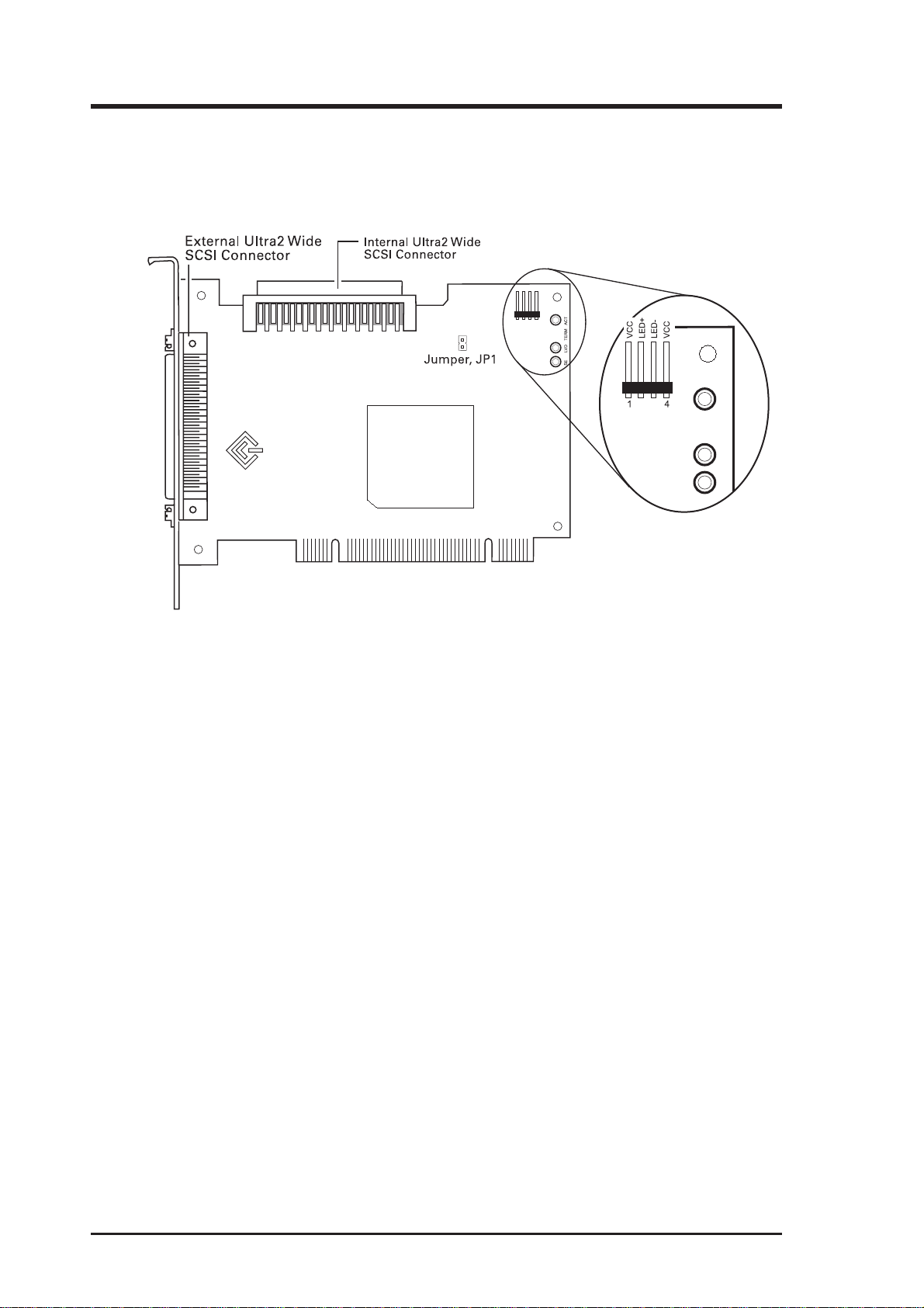
1. Technical Illustration
SE LVD TERM ACT
FIGURE 1 identifies major components pertaining to your PCI-SIU2 host
adapter . You will find it helpful to refer to this illustration while installing the
host adapter and attaching the cables.
ASUS
PCI-SIU2
FIGURE 1 | PCI-SIU2 Board Layout
10 ASUS PCI-SIU2 User’s Manual
Page 11

1. Product Features/Specifications
Product Features
• PCI Compatibility: The PCI Bus is a 32-bit bus with multiplexed
address and data lines. The PCI-SIU2 is compliant with PCI 2.1 bus
protocol, electrical and mechanical specifications.
• Plug and Play: The PCI-SIU2 has an on-board read only memory
(ROM) to provide the necessary configuration mechanisms for installation, configuration, and booting without user intervention.
• 133 MBytes per second PCI burst mode: The 32-bit data path for the
PCI bus structure running in a synchronous mode at 33 MHz gives
maximum operating speeds of 133 MBytes/second.
• 80 MBytes per second data transfer: Up to 80 MBytes/sec synchro-
nous Ultra2 SCSI data transfers for the PCI-SIU2.
• Programmable/Automatic SCSI Termination: Allows the user to
choose between programmable or auto-SCSI termination, eliminating
the need to remove system unit covers each time a change is made in
SCSI bus configuration.
• Onboard BIOS supports MS-DOS, Windows 3.1x: The PCI-SIU2
has the necessary software support on-board–allowing you to run disk
drive operations for MS-DOS and Windows 3.1x without any extra
drivers.
• Operating System Support: Extensively tested and proven reliable,
the PCI-SIU2 guarantees compatibility with DOS/W indows, Windows
95/98, W indows NT , OS/2, SCO Unix, UnixW are, and Novell NetW are.
• ISGE™ Integrated Scatter/Gather Engine: ASUS host adapters have
incorporated advanced hardware functions to provide increased performance in all Scatter/Gather operations.
• No Hardware Jumpers to set: ASUS host adapters embed an intelli-
gent software utility to set configuration options.
• Compatible with Hard Disk, CD-ROM, Optical, T ape, Printer, and
other SCSI products: The PCI-SIU2 is a complete SCSI implementation. All peripherals are compliant with Ultra2 SCSI (L VD), FastSCSI,
SCSI-2 and SCSI-1 and can be used with the PCI-SIU2.
ASUS PCI-SIU2 User’s Manual 11
Page 12

Product Features/Specifications
• 256-byte FIFO: A 256-byte FIFO buffer is designed into the PCI-
SIU2 and is utilized as a caching buffer to manage PCI to SCSI bus
structure timing for data and command transfer.
• Command Queuing: A unique implementation to provide 255 simul-
taneous SCSI commands.
• SCSI compliant: The PCI-SIU2 is fully SCSI compliant, implement-
ing advanced features such as:
• Tag Queuing
• Sync/Async Transfers
• Disconnect / Reselect Arbitration
Product Specifications
Power Requirements
• 5.0 ± 0.25 V at 0.51 Amps maximum not including bus termination
Physical Dimensions
• 5.25” x 3.80” (13.34 cm x 9.96 cm)
Environmental Specifications
Operating Temperature
• 0 to 55°C (32 to 131°F)
• 10% to 90% relative humidity (non-condensing)
Storage Temperature
• -40 to 75°C (-40 to 167°F)
• 5% to 95% relative humidity (non-condensing)
12 ASUS PCI-SIU2 User’s Manual
Page 13

2. Getting Started
2
Host Adapter and the SCSI Bus
The PCI-SIU2 is a bus mastering host adapter which works with the host computer to provide control for the SCSI bus. By daisy chaining peripheral devices together, up to 15 SCSI devices can be connected to the PCI-SIU2. The
host adapter can be placed in any standard PCI slot on the bus.
SCSI Bus Preparation
Peripheral devices attached to the SCSI bus can either be an internal or external device. Each peripheral has a specific device ID, commonly referred to as
a “SCSI ID.” The SCSI ID determines priority when two or more devices are
trying to use the SCSI bus at the same time. No two devices can have the same
ID; the device ID uniquely defines the device to the SCSI bus. The PCI-SIU2
is preset to SCSI ID 7 and should not be changed. This gives it the highest
priority on the SCSI bus. Please refer to your peripheral documentation to
determine switch or jumper settings for SCSI ID’s. Here are some general
guidelines for SCSI IDs:
• SCSI ID numbers don’t have to be sequential, as long as the PCI-SIU2
and each peripheral has a different number. For example, you can
have an internal SCSI peripheral with ID 0, and an external SCSI
periphera1 with ID 6. Gaps in the sequence of numbers don’t matter.
• For internal SCSI peripherals, the SCSI ID usually is set by configur-
ing a jumper on the peripheral.
• For external SCSI peripherals, the SCSI ID usually is set with a switch
on the back of the peripheral.
• SCSI ID 7 has the highest priority on the SCSI bus. The priority of the
remaining IDs, in descending order, is 6 to 0, 15 to 8.
• Most internal SCSI hard disk drives come from the factory preset for
SCSI ID 0.
ASUS PCI-SIU2 User’s Manual 13
Page 14

2. Getting Started
• If you have 8-bit SCSI peripherals, they must use SCSI IDs 0, 1, 2, 3,
4, 5, or 6. SCSI ID 0 is recommended for the first SCSI hard disk drive.
• In Windows 95/98, you can use the Device Manager to view the SCSI
ID (and other details) assigned to each SCSI device installed.
• Through ASUS’s SmartSCSI, you can use the utility to view the SCSI
ID (and other details) assigned to each SCSI device installed.
SCSI Bus Termination
The SCSI bus structure has a length limitation as well as a requirement for
termination at each end of the SCSI cable. The cable is designed to connect in
a daisy chain fashion. No branching is permitted in the SCSI bus. The first
and last physical SCSI device on the SCSI bus must be terminated (see Cabling Examples). T o ensure reliable communication on the SCSI bus, the ends
of the SCSI bus must be properly terminated. This is accomplished when the
peripheral at the end of each cable, or the end of the cable itself, has a terminator installed (or enabled). The peripherals between the ends of each cable must
have its terminator removed (or disabled).
Since the method for terminating a SCSI peripheral can vary widely, refer to
the peripheral’s documentation for instructions on how to enable or disable
termination. Here are some general guidelines for termination:
• Internal Ultra2 peripherals are set at the factory with termination disabled and cannot be changed. Proper termination for internal Ultra2
peripherals is provided by the built-in terminator at the end of the Ultra2 internal SCSI cable.
• Termination on internal SCSI peripherals usually is controlled by manually setting a jumper or a switch on the peripheral, or by physically
removing or installing one or more resistor modules on the peripheral.
• Termination on external SCSI peripherals is usually controlled by installing or removing a SCSI terminator . On some external peripherals,
termination is controlled by setting a switch on the back of the drive.
• By default, termination on the PCI-SIU2 is automatic (the preferred
method). To manually set termination on the PCI-SIU2, see Host
Adapter Setup in Chapter 4.
• Most non Ultra2 SCSI peripherals come from the factory with termination enabled.
14 ASUS PCI-SIU2 User’s Manual
Page 15
2. Getting Started
Mixing UltraSCSI &U2 (LVD) SCSI Devices
The PCI-SIU2 supports legacy drives. However, in order to maximize perfor mance of SCSI I/O’ s it is recommended to only connect LVD (Ultra2) devices
to the PCI-SIU2. If a legacy device is attached to the PCI-SIU2, the devices
attached will be switched to SE (Single-Ended) mode. Then all SE SCSI parameters (# of devices, cable length, cable impedence) will become in effect.
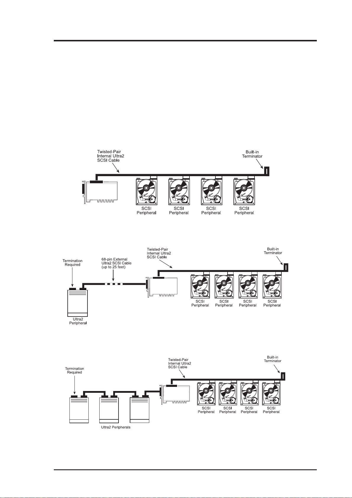
Cabling Examples
ASUS
PCI-SIU2
FIGURE 2 | Connecting internal peripherals
ASUS
PCI-SIU2
FIGURE 3 | Connecting point-to-point external peripheral and internal peripherals
ASUS
PCI-SIU2
FIGURE 4 | Connecting three external peripheral and four internal peripherals
ASUS PCI-SIU2 User’s Manual 15
Page 16

2. Getting Started
PCI-SIU2’ s SCSI termination can be set to auto-termination or programmable
mode via the SmartSCSI Setup Utility. This feature allows the operator to
switch the auto-termination On or Off. If auto-termination is switched Off, the
operator can manually program termination for the host adapter. There are
several ways to manually control terminating the host adapter on the SCSI bus.
The following is a sampling:
ROTCENNOC.TNIROTCENNOC.TXE
OIRANECS
1X NONO
2XNONO
3X X FFOFFO
4X NONO
nip-86
ISCS
)s(eciveD
nip-05
ISCS
)s(eciveD
nip-86
ISCS
)s(eciveD
nip-05
ISCS
)s(eciveD
tiBiHtiBwoL
5XNONO
6X NOFFO
7XX NONO
8XXNONO
9XXXXFFOFFO
01X XNOFFO
11XXNOFFO
21XXX FFOFFO
31X XXFFOFFO
41XX XNOFFO
51XXXNOFFO
NOTE: When mixing 68-pin and 50-pin SCSI devices on the same daisy
chain, it is highly recommended that the 68-pin SCSI device is connected furthest away from the PCI-SIU2 host adapter.
FIGURE 5 | Possible Termination Options Settings
1
Assumption: Host adapter is at the end of the SCSI bus
2
Assumption: Host adapter is in the middle of the SCSI bus
16 ASUS PCI-SIU2 User’s Manual
Page 17
3. Hardware Installation
3
Installation Basics
The internal cable permits connection of multiple internal devices. SCSI devices that are connected to the internal connector are installed inside the host
computer enclosure. The external connector is accesible through the D-shell
connector at the back of the host system and is designed to connect devices
outside the host system enclosure.
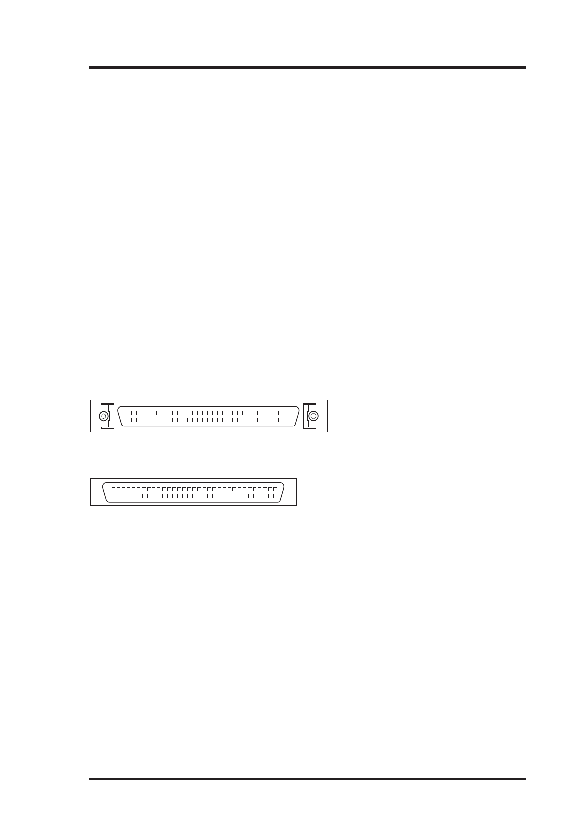
The PCI-SIU2 has one internal 68-pin high-density connector and one external 68-pin high-density connector for a combined support for 15 SCSI devices. The two connectors are the same except for the screw holes on the sides
of the external connector .
High Density External...........
High Density Internal............
FIGURE 5 | Connector Details
NOTE:
Attaching UltraWide or UltraSCSI peripherals to the Ultra2 SCSI segment of the SCSI bus causes the Ultra2 SCSI segment and any attached
peripherals to drop to UltraSCSI performance levels (40 MBytes/sec).
Attaching only Ultra2 peripherals to the PCI-SIU2 ensures that all peripherals on the Ultra2 segment will perform at Ultra2 performance
levels (80 Mbytes/sec).
ASUS PCI-SIU2 User’s Manual 17
Page 18
3. Hardware Installation
Installing the PCI-SIU2 Host Adapter
1 Power down the host computer and all peripherals
Remove the cover from the host system. You may need to refer to the
system manual for cover removal. If necessary, identify the PCI sockets inside the host system with the aid of the system documentation.
2 Use static electricity discharge precautions
Remove possible static discharge potential from any objects that the
host adapter may come in contact with before installation. This can be
accomplished by touching a bare metal chassis rail after you have turned
off the power.
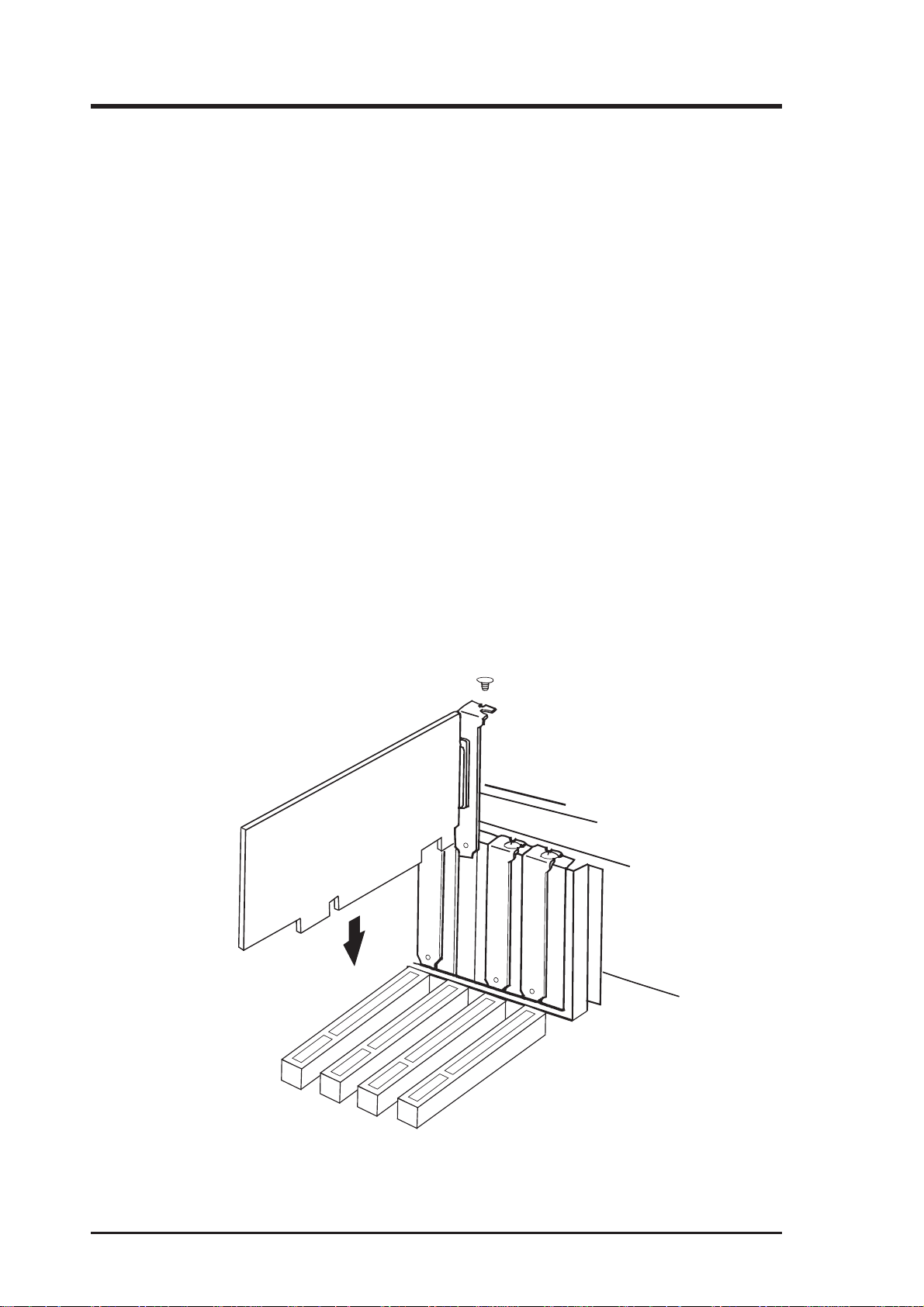
3 Inserting the host adapter
Orient the host adapter for installation so that the external connector is
facing the back of the system unit and align the card with the PCI
connector on the system unit (see FIGURE 6). Holding the adapter by
the mounting bracket and the card edge, match up the card edge connector with the PCI host computer socket and insert the card into the
socket. Once the connector is in the PCI expansion slot socket tighten
the mounting bracket screw to secure the card in place.
FIGURE 6 | Inserting the host adapter into a PCI slot
18 ASUS PCI-SIU2 User’s Manual
Page 19
3. Hardware Installation
4a Installation of internal SCSI devices
A total of 15 SCSI peripherals can be connected to the PCI-SIU2. One
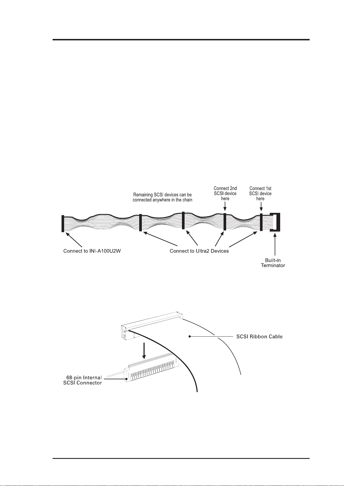
internal 68-pin high density Ultra2 cable is included (see FIGURE 7).
This cable is used to connect internal target devices. The internal cable
is made with multiple connectors attached and used to daisy chain the
host adapters to two or more target devices. The connector on the host
adapter is keyed for proper orientation and insertion. Plug the long end
of the cable to the host adapter and the remaining connectors to the
target SCSI devices. It is important to use the cable with the termination on one end of the cable towards the target device side. The cable
is limited to a total lenghth of 12 meters including external cabling.
Installation of internal cable must be performed before replacing the
cover.
FIGURE 7 |
Self-terminating high-density 68-pin Ultra2 internal cable
(included, may vary in length and number of connectors)
FIGURE 8 | Connecting the 68-pin Ultra2 SCSI cable
ASUS PCI-SIU2 User’s Manual 19
Page 20
3. Hardware Installation
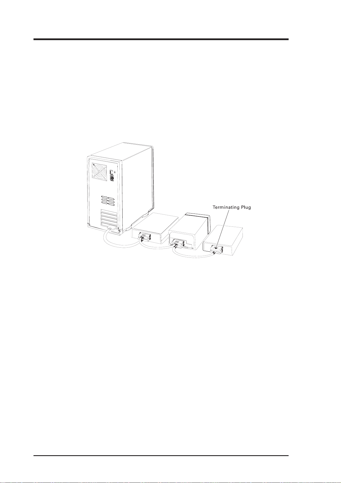
4b Installation of external SCSI devices
Use the 68-pin external Ultra2 SCSI connector to connect your external Ultra2 peripherals. Ultra2 external cables are not included in the
kit. Installation of external SCSI cables can be performed after the
cover has been closed. The cable is limited in length to a total of 12
meters including any internal cabling. The external cable can be daisy
chained to include up to 15 devices with the host adapter in combination with internal devices. The external cable is designed to be inserted only one way, requiring termination at the end peripheral device (FIGURE 9).
FIGURE 9 | External cable connection
NOTE:
We recommend keeping your Ultra2 peripherals seperate from your
non-Ultra2 peripherals. Connecting a non-Ultra2 peripheral to the
Ultra2 SCSI connector forces the Ultra2 SCSI segment and any attached peripherals to drop down to UltraSCSI performance levels (40
MBytes/sec).
T o increase the reliability of the cabling being used with the host adapter, it is
recommended that the following guidelines be observed:
• SCSI-1 – Cabling up to 6 meters (20 feet)
• UltraSCSI – Four devices, up to 3 meters (10 feet)
• UltraSCSI – Eight devices, up to 1.5 meters (5 feet)
• Ultra2 (point-to-point configuration) – Up to 25 meters (82 feet)
• Ultra2 (multiple interconnect config) – Up to 12 meters (39 feet)
• Impedance of the cable should be 120 (±8 ohms); Ultra2
• Impedance of the cable should be 90 (±8 ohms); UltraSCSI & FastSCSI.
• Use high quality shielded connectors for external devices.
20 ASUS PCI-SIU2 User’s Manual
Page 21
3. Hardware Installation
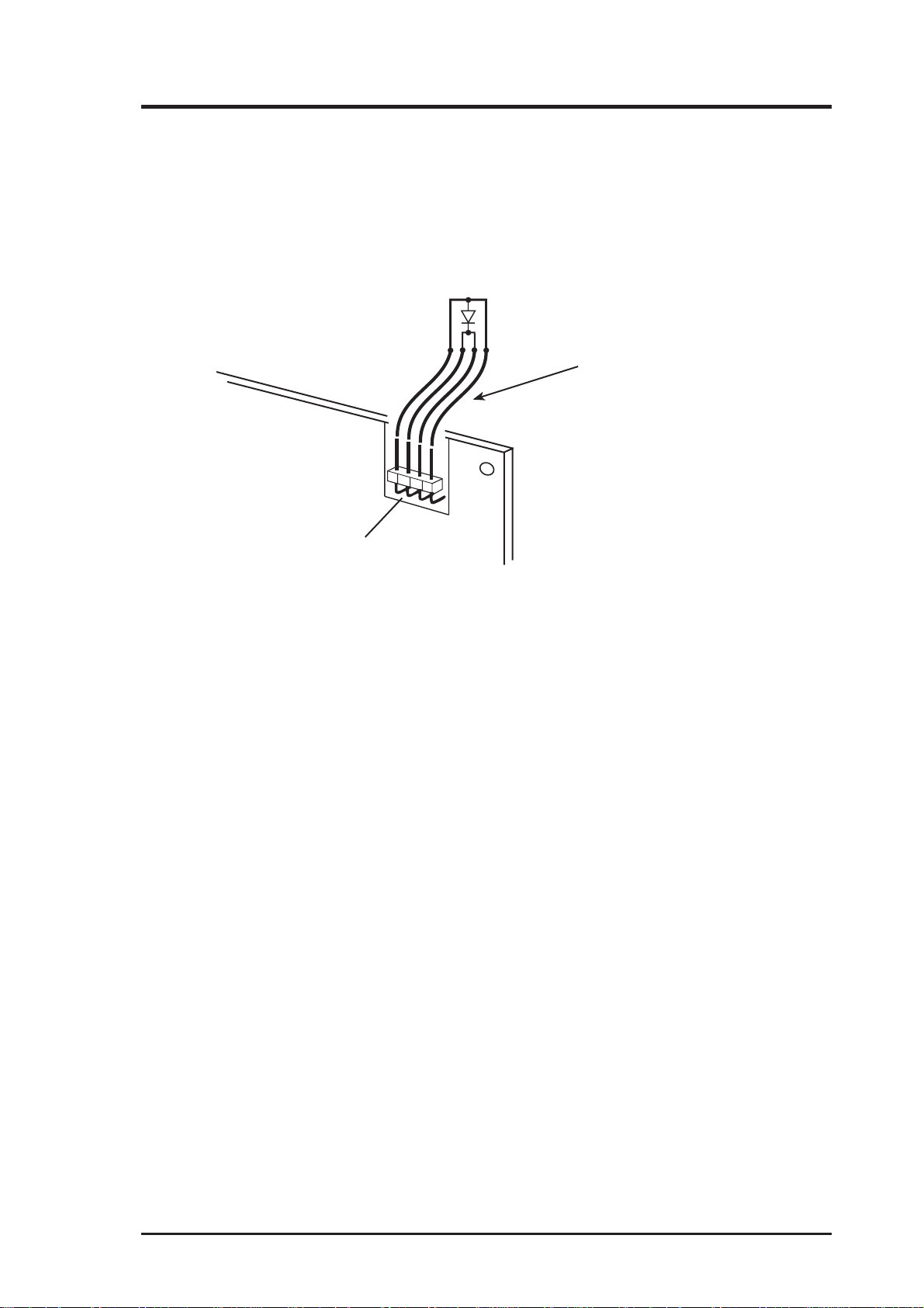
5 Drive activity LED
A drive activity LED is designed into the host adapter to indicate when
a data transfer is being made. Connection to the LED is optional and
cabling is not included with this kit. Each host adapter has one four-pin
connector. Please refer to the host adapter’s illustration (FIGURE 10)
for the LED connector that will accomodate the LED cable.
1
1
LED Connector, J3
Motherboard
Hard Drive
Activity LED cable
FIGURE 10 | Connecting to the motherboard LED
6 Close the cover on the host computer
Visually inspect the configuration you have installed to verify that all
cables have been inserted correctly. Close the cover on the host computer. The hardware installation for the host adapter is now complete.
7 Host computer configuration
Most computer manufacturers with a PCI bus automatically configure
the add on-card or host adapter I/O Port address, IRQ Setting and BIOS
address. If this is not the case with your computer system, you will
need to manually configure your system.
There are two means of configuring the PCI bus from the host computer system:
1. Setting jumpers on the host system motherboard.
2. Setting CMOS BIOS incorporated into the host system.
You will need to refer to the host computer system documentation to
complete PCI bus activation and setup.
If the host system will be using a SCSI device to provide system boot
capability, then the system CMOS drive type settings may need to be
changed. Under some conditions the system will expect the boot disk
to be an IDE drive. This must be changed in order to boot from a SCSI
device.
ASUS PCI-SIU2 User’s Manual 21
Page 22

3. Hardware Installation
8 System startup
The newly installed SCSI bus is now ready to power up. Switch on
peripheral and host computer system power . The system monitor should
display the following information, but may vary, based on the system
BIOS manufacturer.
• The normal Power-On Self Test and memory test procedure.
• The host adapter sign on message including a list of attached SCSI
devices.
The list should match the peripheral devices attached to the bus. In most
cases the host computer system is now configured and ready for use.
Some situations will require that a low-level format be performed using the host adapter SmartSCSI Setup Utility to initialize a SCSI disk
drive and lay the foundation for a bootable SCSI drive.
9 SmartSCSI Setup Utility
The SmartSCSI Setup Utility simplifies the SCSI installation process
by eliminating the need for opening the system to change system jumpers and switch settings. All necessary host adapter functions are accessible through the utility , simplifying customization for your system
needs. ASUS’ s SmartSCSI Setup Utility is divided into five segments
identified by: Scan Bus; Device Setup; Adapter Setup; BIOS Setup;
and Disk Utility. These program functions are accessible by typing
<CTRL><I> at the boot-up prompt when the message comes to view .
Hard Disk Drive Preparation
A new SCSI disk drive is normally low-level formatted at the factory to simplify installation. Every SCSI hard disk drive must be physically low-level
formatted, partitioned, and logically formatted before it can be used to store
data. SCSI hard disks are physically low-level formatted at the factory and do
not usually need to be formatted again.
If you connect a newer SCSI hard disk drive to your SCSI card, you must
partition and logically format the drive. For DOS and Windows (3.x and 95)
use the DOS Fdisk and Format commands (see your computer, DOS, and
Windows documentation). For other operating systems, see your operating
system documentation.
If you are booting from a SCSI hard disk drive, make sure the Hard Disk (or
Drives) setting in your computer’s CMOS setup program is set to None or No
Drives Installed, as is required for SCSI hard disk drives. See your computer
documentation for details.
22 ASUS PCI-SIU2 User’s Manual
Page 23

3. Hardware Installation
If both SCSI and non-SCSI (for example, IDE) disk drives are installed, then
the non-SCSI disk drive is typically the boot drive. If your computer supports
BBS (BIOS Boot Specification), both SCSI and non-SCSI disk drives can
coexist and you can specify which drive to boot from. Refer to your computer
documentation for more information.
Low-level Format
A low-level format will erase any data that is stored on the target disk. Before
attempting to perform a low-level format be sure the data on the target disk
has been backed up. A low-level format can be achieved via the SmartSCSI
Setup Utility for PCI-SIU2.
The low level format sets the media to a state which is easily recognized by
the host adapter on the SCSI bus. Once this format is completed, you will
need to partition the drive. Refer to your operating system documentation for
further information on partitioning drives.
Multiple Initiators & Clustering
A multiple initiator environment is one in which the SCSI bus has two or more
host adapters. T o work in a cluster , the host adapters must perform properly in
such an environment by not resetting the bus without an explicit host command, for example. ASUS’s host adapters are built for multi-initiator operation and adhere strictly to the SCSI standard.
FIGURE 11 illustrates the principal components in a cluster’s I/O system. It
shows a simple cluster with two servers sharing access to online storage (the
basic model for Microsoft’s MSCS clusters). Both servers contain a host
adapter that provides access to the shared external I/O bus. Servers can share
disks or arrays attached to this shared I/O bus. The operating system controls
contention for disk access by using either a component called a distributed
lock manager (DLM) to resolve access conflicts or a shared-nothing model
that partitions disks and arrays, giving each server control over a subset of the
storage under normal circumstances. MSCS uses the shared-nothing approach.
Under some circumstances multiple initiators can be used on a single SCSI
bus. The bus is configured to have more than one host adapter inserted into at
least two distinctly different computer systems sharing peripheral devices. In
these circumstances, it is possible to have one of the two computer systems
turned off. Under these conditions,
ASUS PCI-SIU2 User’s Manual 23
Page 24

3. Hardware Installation
the host adapter has a jumper that can be enabled (closed) to set the active onboard termination on all the time, regardless of whether power is applied or
not. The host adapter is shipped without the jumper installed and need not be
changed in most cases. Visually inspect the configuration you have installed
to verify that all cables have been inserted correctly.
ASUS PCI-SIU2
ASUS PCI-SIU2
FIGURE 11 | Simple multiple initiator model
24 ASUS PCI-SIU2 User’s Manual
Page 25

4. Host Adapter Setup
4
Running the SmartSCSI Setup Utility
To start the SmartSCSI Setup Utility, verify that all devices attached to the
SCSI bus are powered up when the host computer system is turned on. Once
the power switch has been turned on and the system begins its on screen power
up sequence, the ASUS banner will be displayed for a brief period. During this
time the ASUS SmartSCSI Setup Utility is accessible by pressing the <Ctrl>
key and the letter<I> key at the same time. When displayed on your system
monitor, the following message indicates that the SmartSCSI utility is ready to
accept your keyboard input.
!!! Press <Ctrl> <I> for SmartSCSI Setup Utility !!!
FIGURE 12 | SmartSCSI’ s menu driven interface
ASUS PCI-SIU2 User’s Manual 25
Page 26

4. Host Adapter Setup
Main Menu Options
SmartSCSI’s main menu provides five possible setup options for meeting your
system configuration:
Scan Bus
Choosing this option results in the host adapter utility to scan the SCSI bus to
determine peripheral devices attached to the host adapter . All device ID’ s are
displayed on the screen including SCSI ID’s without devices attached. This
allows for a better definition of location and priority on the SCSI bus.
• A device ID should only be changed if it conflicts with another device
address on the same bus. Refer to your peripheral documentation for
changing SCSI ID’s.
• The best ID for a bootable hard disk is SCSI ID-0.
Device Setup
Asynchronous T ransfer. Use this option to set the synchronous data transfer
mode. PCI-SIU2 will transfer data at a maximum rate of 80 MBytes per second in synchronous mode and a maximum rate of 10 Mbytes per second in
asynchronous mode. Use this option to set the synchronous data transfer mode.
The default setting for this option is for synchronous operation. (No)
Maximum Synchronous T ransfer Rate. This option determines the speed at
which data is moved across the SCSI cable. PCI-SIU2 has the option of running from 80 MBytes per second in synchronous mode.
DOS Space > 1 GB. Using this option allows for single disk capacities to be
extended up to 8 GBytes (Yes). Please refer to the Troubleshooting Section
titled DOS Space > 1 GB for further information on this feature.
• (NO) DOS limits the number of cylinders per drive to 1024. The host
adapter defines head and sector usage to 64 heads and 32 sectors. This
format allows for maximum capacity of 1 gigabyte per disk storage.
• (YES) The upper limit can be extended from 1 GByte to 8 GBytes by
increasing the number of heads to 255 and number of sectors used per
track to 63. NOTE: This is a powerful option. Data can be lost by
changing settings.
26 ASUS PCI-SIU2 User’s Manual
Page 27

4. Host Adapter Setup
Spin Up Disk Drive. This option is used to initiate motor spin-up for SCSI
disk drives. The host adapter BIOS can limit system power requirements during power-up. This is accomplished by signaling the device to start at delayed
intervals (default setting will be ‘No’).
Enable Disconnect. The host adapter uses this option to allow a device to
temporarily disconnect from the SCSI bus (referred to as disconnect/reconnect). This allows the host adapter to perform other functions on the bus while
the device is temporarily disconnected. The device and the host adapter can
then reconnect when the bus is needed (default setting will be ‘Yes’).
Enable Wide Negotiation. This option determines whether the host adapter
initiates wide data transfer with the specified SCSI device. However, not all
SCSI devices can handle wide data transfer negotiations properly , which may
cause system failure. Certain old CD-ROM, CD-Recordable, and tape drives
cannot handle a Wide Transfer negotiation request from the PCI-SIU2 and
may fail to start the system. In such cases, use SmartSCSI to disable (NO
check) the W ide Negotiation setting for the SCSI ID of the anomalous device.
Adapter Setup
Host Adapter SCSI Bus ID. Used to change the adapter ’s SCSI ID on the
SCSI bus. The narrow host adapters provides eight ID’ s available numbered 07, with 7 having the highest priority (and ID-7 reserved for the host adapter).
Installation of multiple host adapters is permitted on the same SCSI bus. This
option allows the system to have more than one SCSI bus attached. Under
these conditions, SCSI ID’ s must be mutually exclusive.
SCSI T erminators. This option is used to set host adapter termination located
on the host adapter card. This option is also used to manually control termination on the host adapter. The normal setting for this option is auto.
SCSI Parity Check ON. Select this option to enable or disable parity checking on the SCSI bus by the host adapter. The default setting for this option is
ON (Yes).
ASUS PCI-SIU2 User’s Manual 27
Page 28

4. Host Adapter Setup
BIOS Setup
Enable Host Adapter BIOS. This option controls the host adapter usage of
SCSI disk I/O routines inside the host adapter BIOS. By disabling this option
you will eliminate the host adapter’s ability to utilize boot capabilities in PCISIU2. Setting this to “no” will also disable all subsequent features displayed
by this on-screen panel. The default setting will be on. (Yes)
Boot Device ID. This option selects which SCSI device will be the designated
boot device for the system. The default ID for this option is 0.
BIOS Support for Bootable CD-ROM. This option allows users to boot
from a bootable CD by replying with Yes at the prompt. Only one bootable
CD-ROM will be allowed at a time. The default setting will be off. (No)
BIOS Treat Removable Disks as Fixed Disk. This option is able to treat
removable disks as fixed disks. W ith this option selected you can run removable disk media without additional software drivers. The default setting will
be off. (No)
Disk Utility
These functions will be displayed when a device has been highlighted. Once a
menu has been pulled up, the host adapter will scan all devices and display all
necessary information. Selecting a device allows you to perform either of
these two following actions:
Verify Disk. This option will verify the media of a successfully formatted
device and verify that the drive is functioning properly. Verify will also identify and flag any bad sectors on the disk so that during operation these flagged
sectors will not be used. If a bad sector is found you are given two options
shown below:
• Reassign will assign the flagged location to another sector on the disk.
• Skip will not reassign the flagged location.
Format Disk. Use this option to perform a low level disk format on the target
device. The format will erase all data resident on the targeted disk drive. Refer
to the section titled “Hard Drive Preparation” for additional information.
CAUTION: A low-level format destroys all data on the drive. Be
sure to back up your data before performing this operation. You cannot abort a low-level format once it
has started.
28 ASUS PCI-SIU2 User’s Manual
Page 29

5. MS-DOS Driver Installation
5
Overview
The ASUS ASPI driver will support extended SCSI command functions for
MS-DOS 3.30 or later. The on-board BIOS initialized during the power up
boot routine only supports MS-DOS hard disk operation. If peripherals other
than disks are used, such as CD-ROM or MO, the ASUS ASPI driver will need
to be installed in addition to ASUS CD-ROM and MO drivers.
Installation
The installation procedure guides you through the installation of the ASUS
DOS ASPI. The installation procedure described here requires some experience in MS-DOS setup and administration. The device driver is transferred
from the PCI-SIU2 DRIVER DISK to the hard drive where it is automatically
initialized during the system boot routine.
The PCI-SIU2 DRIVER DISK contains one installation program that per-
form the same task.
Installing the ASPI drivers to an existing MS-DOS
system
The ASPI driver is found on the PCI-SIU2 DRIVER DISK . It is important
that the SCSI bus hardware, and operating system are installed correctly before
proceeding further . If you need help installing the MS-DOS operating system,
please refer to the MS-DOS manual before proceeding.
1. Turn on host system and boot into MS-DOS.
2. Insert the PCI-SIU2 DRIVER DISK into your floppy drive.
3. At the MS-DOS prompt, change to your active floppy drive (e.g.,
type A: <ENTER> ).
4. T ype DOSSETUP <ENTER> (A series of scr eens will guide you
through the installation of the ASPI device drivers).
ASUS PCI-SIU2 User’s Manual 29
Page 30

5. MS-DOS Driver Installation
5 The first screen sets the installation drive and directory that the ASPI
driver will be installed on. Follow the on-screen directions and/or options to continue the installation.
6 To activate the device driver, reboot the system by selecting the Re-
boot Now option at the end of the installation process.
ASPI Manager Command Line Options
Below is a list of command line options. The ASUS ASPI Manager , ASPIA100,
supports command line switches to optimize driver operation. From inside the
CONFIG.SYS file for MS-DOS, use the following format when modifying
the device driver switches:
The standard format for command line switches is:
Device = C:\INIASPI\ASPIA100.SYS [Driver Config Option]
/D Verbose Mode provides detailed information about the driver on
system command line when the driver is initialized.
/L Driver scan eight LUNs for each SCSI Target.
/Bb,dd Scan device only on PCI BUS #b, PCI DEVICE #dd
The range for “b” is from 0 to 7.
The range for “dd” is from 0 to 20.
/Bb Scan all the devices on the PCI BUS #b
The range for “b” is from 0 to 7.
/Sdd Scan device only on the PCI BUS #0 and device #dd
The range for “dd” is from 0 to 20.
/CCBSx Defines the maximum number of concurrent I/O that driver sup-
ports. The range for “x” is from 1 to 16.
30 ASUS PCI-SIU2 User’s Manual
Page 31

5. MS-DOS Driver Installation
ASPI CD-ROM Driver Command Line Options
INICD.SYS is a DOS device driver for supporting SCSI CD-ROM drives. It
is the interface between MSCDEX.EXE (supplied by Microsoft®) and the physical CDROM drive. INICD.SYS is automatically loaded in the CONFIG.SYS
start up file by the ASUS DOSSETUP or SETUP programs. INICD.SYS requires that the ASUS ASPI Manager be loaded. INICD.SYS can be loaded
with either the DEVICE= or DEVICEHIGH= command. INICD.SYS can be
found on PCI-SIU2 DRIVER DISK. Below is a list of command line options
and examples.
/D: /d: This option is used to specify the name of the device driver. The
name specified must also be passed to MSCDEX.EXE on it’s
command line (Using the same /D: or /d: option). The name specified must be 8 or less characters in length. Valid characters are
the A-Z, a-z, 0-9 and underscore. The name must start with a
letter.
Examples: /D:INICD001
/d:mscd001
/d:MYCD01
/T /t This option is used to specify a Time out value to be used when
sending commands to a CDROM drive. If a CDROM drive does
not respond to a command within the specified time out then the
command will be aborted and an appropriate error message will
be displayed. The time out value is specified in minutes. Valid
values are 1-9 and D or d. The D or d values are used to Disable
the time out mechanism. If the time out mechanism is disabled
then faulty hardware can lock up the system.
Examples: /T4
/Td
/TD
/T1
ASUS PCI-SIU2 User’s Manual 31
Page 32

5. MS-DOS Driver Installation
/X /x This option is used to exclude particular CD-ROM drives. Ex-
cluded CDROM drives are identified by specifying the host
adapter, tar get id and lun. These values are spereated by a colon.
Groups of CDROM drives (or wild cards) can also be identified.
Below are examples of the different ways CDROM drives can
be excluded:
/X0:1:2
This will exclude the drive on Host Adapter 0, with target ID 1
and lun 2.
/X0:2
This will exclude the drive on Host Adapter 0, with target ID 2
and ANY lun
/X0
This will exclude ALL drives on Host Adapter 0.
Sample CONFIG.SYS and AUTOEXEC.BAT Files
These samples assume that the user has loaded the ASUS drivers in the following directory: c:\iniaspi.
Config.sys:
DEVICEHIGH=c:\iniaspi\aspia100.sys
DEVICEHIGH=c:\iniaspi\inicd.sys /D:INICD001
Explanation:
The first line loads the ASPI manager and the second line loads the CDROM
driver specifying the device name INICD001.
Autoexec.bat:
C:\INIASPI\Mscdex /D:INICD001
Explanation:
This line will load the Microsoft supplied mscdex.exe file instructing it to
attach to the CD-ROM device driver INICD001. Setup copies Mscdex to the
C:\INIASPI directory during installation.
32 ASUS PCI-SIU2 User’s Manual
Page 33

5. MS-DOS Driver Installation
ASPI Disk Driver Command Line Options
INIDISK.SYS is a DOS block device driver for supporting SCSI fixed disks,
removable disks and MO devices. INIDISK.SYS is automatically loaded in
CONFIG.SYS start up file by the ASUS DOSSETUP or SETUP programs.
INIDISK.SYS requires that the ASUS ASPI Manager be loaded. INIDISK.SYS
can be loaded with either the DEVICE= or DEVICEHIGH= command.
INICD.SYS can be found on the PCI-SIU2 DRIVER DISK 1. Below is a list
of command line options and examples.
/R /r This option specifies the number of logical drives to reserve for
MO and removable disk devices. MO and removable disks media are capable of being partitioned just like a fixed disk. For
every DOS partition on the media a logical DOS drive letter will
be available. INIDISK.SYS will support as many logical drives
as required (up to the maximum supported by DOS) based on the
partitioning of the media that is present when your system boots.
However, the media may be removed at any time and a new disk
may be inserted. The new disk may have more (or less) partitions then the original disk. The /R /r option is used to reserved
drive letters at start up in order to facilitate a disk change to a
disk with more partitions than the original disk present at boot
time. The value after the /R /r option determines how many drive
letters will be reserved on a device basis. For example, if the user
specifies a /R4 option and there are two removable devices attached to the SCSI bus, then a total of eight (8) drive letters will
be reserved.
/T /t This option is used to specify a Time out value to be used when
sending commands to a SCSI drive. If a SCSI drive does not
respond to a command within the specified time out then the command will be aborted and an appropriate error message will be
displayed. The time out value is specified in minutes. Valid values are 1-9 and D or d. The D or d values are used to Disable the
time out mechanism. If the time out mechanism is disabled then
faulty hardware can lock up the system.
Examples: /T4
/Td
/TD
/T1
ASUS PCI-SIU2 User’s Manual 33
Page 34

5. MS-DOS Driver Installation
/X /x This option is used to exclude particular SCSI drives. Excluded
SCSI drives are identified by specifying the host adapter, target
id and lun. These values are spereated by a colon. Groups of
SCSI drives (or wild cards) can also be identified. Below are
examples of the different ways SCSI drives can be excluded:
/X0:1:2
This will exclude the drive on Host Adapter 0, with target ID 1
and lun 2.
/X0:2
This will exclude the drive on Host Adapter 0, with target ID 2
and ANY lun
/X0
This will exclude ALL drives on Host Adapter 0.
SAMPLE CONFIG.SYS
These samples assume that the user has loaded the ASUS drivers in the following directory: c:\iniaspi.
Config.sys:
DEVICEHIGH=c:\iniaspi\aspia100.sys
DEVICEHIGH=c:\iniaspi\inicd.sys /R2
Explanation:
The first line loads the ASPI manager and the second line loads the SCSI disk
driver specifying that a minimum of two drive letters be reserved for each MO
and removable disk attached to the SCSI bus.
ASPI Partition & Format Utility
INIFDISK.EXE is a DOS ASPI partition and format utility. It requires the
ASPIA100.SYS and INIDISK.SYS drivers to be loaded in order for it to function properly . INIFDISK.EXE is installed by the ASUS DOSSETUP or SETUP
programs. Upon invocation, the initial screen will have two windows. The top
window will list all of the SCSI devices installed in the system. The user can
highlight a particular device by using the up and down arrow keys. The bottom window will display information about the device that is currently highlighted in the top window. Inifdisk.exe can partition and format any SCSI
storage device that is not being controlled by the BIOS, this includes SCSI
disks, magnetic optical drives, and removable media devices. INIFDISK will
display two screens in which the bottom portion will explain all commands
possible in the top window.
34 ASUS PCI-SIU2 User’s Manual
Page 35

6. MS Win 95/95b (OSR2) Driver Installation
6
Overview
PCI-SIU2 will support Microsoft W indows 95 and Windows 95B (OSR2) with
the addition of a software driver. The installation procedure described here
requires some experience in Windows 95 system setup and administration.
The device driver is transferred from the PCI-SIU2 Driver Disk 1 to the hard
drive where it is automatically initialized during the system boot routine.
The following files are used for installation and will be found on the PCI-
SIU2 Driver Disk 1 in the A:\win95 directory:
\WIN95\INIA100.MPD
PCI-SIU2 SCSI Host Adapter Windows 95 miniport driver.
\WIN95\INIA100.INF
Windows 95 installation information file.
Installation
The PCI-SIU2 driver developed for Windows 95 is loaded during the system
boot routine and will remain resident on the drive. This is accomplished by
following one of the three installation procedures listed:
• New Windows 95 and Windows 95B (OSR2) installation.
• Adding the ASUS Windows 95 device driver to an existing Windows
95 or Windows 95B (OSR2) system.
• Updating INIA100.MPD device driver
The procedures described to make changes to the system have distinct differ ences. It is strongly suggested that the selected procedure be read and understood before proceeding with the system configuration changes. Please read
the instructions carefully .
To determine which version of Windows 95 you have installed on your system, check the date of the KRNL32.DLL file located in your Windows directory. A file date of 07/11/95 belongs to Windows 95, first release; 12/31/95
belongs to Windows 95a or 95 with Service Pack 1; 08/24/96 reflects Windows 95b or OSR2.
ASUS PCI-SIU2 User’s Manual 35
Page 36

6. MS Win 95/95b (OSR2) Driver Installation
New Windows 95/95a Installation
These instructions will guide you through the installation of the ASUS host
adapter driver while installing Windows 95. Windows 95 will be installed
from either a CD-ROM or floppy diskettes. It is important that the hardware
and DOS 4.01 or higher have been installed successfully before proceeding
further . If installing from a SCSI CD-ROM drive, it is important that the ASUS
ASPI driver, and CD-ROM driver be installed before proceeding further.
1 Access the Windows 95 CD-ROM from either the DOS prompt or from
Microsoft Windows 3.x File Manager. Execute the SETUP.EXE program and follow the instructions on your screen. If you are installing
from floppy diskette, insert the W indows 95 Setup Disk 1 in your floppy
disk drive and boot your system. Follow the instructions on your screen.
2 Once a Windows 95 session is established, use your installed mouse or
the appropriate key strokes to select MY COMPUTER from the MAIN
DESKTOP. Execute the following steps:
• Select CONTROL PANEL from within the MY COMPUTER
icon.
• Select SYSTEM from within the CONTROL PANEL group
• Select DEVICE MANAGER tab from within the SYSTEM group
• Select the OTHER DEVICES category from within the DEVICE
MANAGER listing.
• Select the PCI-SCSI Bus Controller sub-category from within
the OTHER DEVICES listing.
• In the PCI-SCSI Bus Controller Properties window, select the
DRIVER tab, then select “CHANGE DRIVER...”.
• In the SELECT HARDWARE TYPE window , select SCSI CON-
TROLLERS.
• In the SELECT DEVICE window, select “HAVE DISK...”.
36 ASUS PCI-SIU2 User’s Manual
Page 37

6. MS Win 95/95b (OSR2) Driver Installation
3 In the INSTALL FROM DISK window, enter the ASUS Driver path
name:
• Insert the PCI-SIU2 DRIVER DISK 1 into drive A:
• Type: A:\WIN95, select “OK”
4 Select PCI SCSI Host Adapter, select “OK”, then “OK” again to
install the INIA100.MPD driver onto your hard disk drive. It may be
necessary to direct Windows to look for the driver in A:\win95 before
the driver can be copied. This step may need to be repeated mor e than
once.
5 Following installation of the ASUS PCI-SIU2 Windows 95 driver for
all channels, reboot your system to activate the SCSI device driver.
6 It is highly recommended that the ASUS Windows 95 device driver
has been properly installed by selecting MY COMPUTER from the
desktop. Then select CONTROL PANEL:
• Select SYSTEM from within the CONTROL PANEL group,
• Select DEVICE MANAGER from within the SYSTEM group,
• Select SCSI CONTROLLERS from within the DEVICE MAN-
AGER listing, and
• Select PCI SCSI Host Adapter from within the SCSI CONTROL-
LER listing. If “This device is working properly” is displayed
under Device Status, the driver has been correctly installed.
ASUS PCI-SIU2 User’s Manual 37
Page 38

6. MS Win 95/95b (OSR2) Driver Installation
Existing Windows 95/95a System
These instructions will guide you through the installation of the ASUS host
adapter to an existing Windows 95 system. Windows 95 will automatically
detect the presence of new hardware in Plug and Play compliant systems. It is
important that the ASUS hardware has been properly installed before proceeding further .
1 Microsoft Windows 95 will detect the presence of new hardware upon
boot-up and will display a dialog window titled NEW HARDWARE
FOUND and PCI SCSI BUS CONTROLLERS will be highlighted.
• Select: DRIVER FROM DISK PROVIDED BY HARDWARE
MANUF ACTURER, then “OK”
• Select SCSI CONTROLLER from the list of available devices,
then select “HAVE DISK...”
2 In the INSTALL FROM DISK window that is displayed, enter the ASUS
Driver path name:
Insert PCI-SIU2 Driver Disk 1 into drive A:
Type: A:\WIN95, select “OK”
3 Select PCI SCSI Host Adapter, select “OK”, then “OK” again to
install the INIA100.MPD driver onto your hard disk drive. It may be
necessary to direct Windows to look for the driver in A:\win95 before
the driver can be copied. This step may need to be repeated mor e than
once.
4 This completes loading the Host Adapter Driver . You must now reboot
your system to activate the SCSI device driver. .
38 ASUS PCI-SIU2 User’s Manual
Page 39

6. MS Win 95/95b (OSR2) Driver Installation
5 It is highly recommended that you verify the ASUS PCI-SIU2 Win-
dows 95 device driver by selecting MY COMPUTER from the desktop. Then select CONTROL PANEL:
• Select SYSTEM from within the CONTROL PANEL group,
• Select DEVICE MANAGER from within the SYSTEM group,
• Select SCSI CONTROLLERS from within the DEVICE MAN-
AGER listing, and
• Select the PCI SCSI Host Adapter from within the SCSI CON-
TROLLER listing. If “This device is working properly” is displayed under Device Status, the driver has been correctly installed.
ASUS PCI-SIU2 User’s Manual 39
Page 40

6. MS Win 95/95b (OSR2) Driver Installation
Updating the ASUS Win 95/95a Device Driver
1 Once a Windows 95 session is established, use your installed mouse or
the appropriate key strokes to select MY COMPUTER from the Main
Desktop. Execute the following steps:
• Select CONTROL PANEL from within the MY COMPUTER
group.
• Select SYSTEM from within the CONTROL PANEL group.
2 Select the DEVICE MANAGER tab from within the SYSTEM group.
• Select the SCSI CONTROLLERS category from within the DEVICE MANAGER listing.
• Select one of the PCI SCSI Host Adapter sub-categories from
within the SCSI CONTROLLERS listing (or select any other PCISIU2 class of drivers if you are using an older ASUS board).
• In the SCSI HOST ADAPTER PROPERTIES window, select the
DRIVER tab, then select “CHANGE DRIVER...”.
• In the SELECT DEVICE window, select “HAVE DISK...”.
3 In the INSTALL FROM DISK window, enter the ASUS Driver path
name:
• Insert the PCI-SIU2 Driver Disk 1 into drive A:
• Type: A:\WIN95, select “OK”
4 Select PCI SCSI Host Adapter, select “OK” to install the
INIA100.MPD driver onto your hard disk drive.
It may be necessary to direct W indows to look for the driver in A:\win95
before the driver can be copied. This step may need to be repeated
more than once.
This completes updating the Host Adapter Driver . Follow the on-screen directions to restart you computer and activate the new driver .
40 ASUS PCI-SIU2 User’s Manual
Page 41

6. MS Win 95/95b (OSR2) Driver Installation
It is highly recommended that you verify the ASUS PCI-SIU2 Windows 95
device driver by selecting MY COMPUTER from the desktop. Then select
CONTROL PANEL:
• Select SYSTEM from within the CONTROL PANEL group,
• Select DEVICE MANAGER from within the SYSTEM group,
• Select SCSI CONTROLLERS from within the DEVICE MANAGER
listing, and
• Select the PCI SCSI Host Adapter from within the SCSI CONTROL-
LER listing. If “This device is working properly” is displayed on your
screen, the driver has been correctly installed.
New Windows 95B (OSR2) Installation
These instructions will guide you through the installation of the ASUS host
adapter driver while installing Windows 95B (OSR2). Windows 95B will be
installed from either a CD-ROM or floppy diskettes. It is important that the
hardware and DOS 4.01 or higher have been installed successfully before proceeding further . If installing from a SCSI CD-ROM drive, it is important that
the ASUS ASPI driver, and CD-ROM driver be installed before proceeding
further.
1 Access the Windows 95B CD-ROM from the DOS prompt. Since OSR2
is never an upgrade version, you must do a new install from a DOS
prompt. Execute the SETUP.EXE program and follow the instructions on your screen. If you are installing from floppy diskette, insert
the W indows 95 Setup Disk 1 in your floppy disk drive and boot your
system. Follow the instructions on your screen.
2 Once a Windows 95 session is established, use your installed mouse or
the appropriate key strokes to select MY COMPUTER from the MAIN
DESKTOP. Execute the following steps:
• Select CONTROL PANEL from within the MY COMPUTER group
• Select SYSTEM from within the CONTROL PANEL group,
• Select DEVICE MANAGER tab from within the SYSTEM group
• Select the OTHER DEVICES category from within the DEVICE
MANAGER listing
• Select one of the PCI-SCSI Bus Controller sub-category from within
the OTHER DEVICES listing
ASUS PCI-SIU2 User’s Manual 41
Page 42

6. MS Win 95/95b (OSR2) Driver Installation
• In the PCI-SCSI Bus Controller Properties window, select the DRIVER
tab, then select “UPDATE DRIVER...”
• Insert PCI-SIU2 Driver Disk 1 into drive A:
• Select YES, click Next, and Windows will search for the driver
• Select the OTHER LOCATION
• Type A:\WIN95, then select “OK”
• Select “FINISH”
• At window “Insert Disk labled PCI-SIU2 Driver Disk 1” , select “OK”
• At window titled “Copying file”, replace the highlighted directory path
with A:\WIN95, then select “OK” this will complete loading the
INIA100.MPD driver onto your hard disk drive. This step may need to
be done more than once.
3 Following installation of the ASUS PCI-SIU2 Windows 95 driver, re-
boot your system to activate the SCSI device driver.
4 It is highly recommended that you verify Initio’s Windows 95 device
driver by selecting MY COMPUTER from the desktop. Then select
CONTROL PANEL:
• Select SYSTEM from within the CONTROL PANEL group,
• Select DEVICE MANAGER from within the SYSTEM group,
• Select SCSI CONTROLLERS from within the DEVICE MAN-
AGER listing, and
• Select the PCI SCSI Host Adapter from within the SCSI CON-
TROLLER listing. If “This device is working properly” is displayed on your screen, the driver has been correctly installed.
This completes loading the Host Adapter Driver, follow the on-screen directions to complete the Windows 95 installation. Exit and reboot the system to
activate the device driver .
42 ASUS PCI-SIU2 User’s Manual
Page 43

6. MS Win 95/95b (OSR2) Driver Installation
Existing Windows 95B (OSR2) System
These instructions will guide you through the installation of the ASUS host
adapter to an existing Windows 95 system. Windows 95 will automatically
detect the presence of new hardware in Plug and Play compliant systems. It is
important that the ASUS PCI-SIU2 hardware has been properly installed before proceeding further .
1 Microsoft Windows 95 will detect the presence of new hardware upon
boot-up and will display a dialog window titled “update Device driver
wizard”
2 Insert the PCI-SIU2 Driver Disk 1 into floppy drive,:
• Select “NEXT”
• Select the “OTHER LOCATION”
• Type A:\Win95, then select “OK”
• Select “FINISH”
• At window “Insert Disk labled PCI-SIU2 Driver Disk 1”, select
“OK”
• At window titled “Copying file”, replace the highlighted directory path with A:\Win95, then select “OK” this will complete loading the INIA100.MPD driver onto your hard disk drive. Restart
your computer. This step may need to be done more than once.
3 It is highly recommended that you verify the ASUS PCI-SIU2 Win-
dows 95 device driver by selecting MY COMPUTER from the desktop. Then select CONTROL PANEL:
• Select SYSTEM from within the CONTROL PANEL group,
• Select DEVICE MANAGER from within the SYSTEM group,
• Select SCSI CONTROLLERS from within the DEVICE MAN-
AGER listing, and
• Select the PCI SCSI Host Adapter entries from within the SCSI
CONTROLLER listing. If “This device is working properly” is
displayed on your screen, the driver has been correctly installed.
ASUS PCI-SIU2 User’s Manual 43
Page 44

6. MS Win 95/95b (OSR2) Driver Installation
Updating ASUS W in 95B (OSR2) Device Driver
1 Once a Windows 95 session is established, select MY COMPUTER
from your desktop. Execute the following steps:
• Select CONTROL PANEL from within the MY COMPUTER
group
• Select SYSTEM from within the CONTROL PANEL group
• Select the DEVICE MANAGER tab from within the SYSTEM
group
• Select the SCSI CONTROLLERS category from within the DE-
VICE MANAGER listing
• Select the PCI SCSI Host Adapter sub-categories from within
the SCSI CONTROLLERS listing
2 In the SCSI HOST ADAPTER PROPERTIES window, select the
DRIVER tab, then select “UPDATE DRIVER...”
• Select “Next”
• Select the “OTHER LOCATION”
• Type A:\WIN95, then select “OK”
• Select “FINISH”
• At prompt “Insert Disk labled PCI-SIU2 Driver Disk 1,” select
“OK”
• At prompt “Copying file”, replace the highlighted directory path
with A:\win95, then select “OK.” This will complete loading the
INIA100.MPD driver onto your hard disk drive.
This completes updating the Host Adapter Driver. Follow the on-screen directions to restart you computer and activate the new driver .
It is highly recommended that you verify Initio’ s Windows 95 device driver by
selecting MY COMPUTER from the desktop. Then select CONTROL
PANEL:
• Select SYSTEM from within the CONTROL PANEL group,
• Select DEVICE MANAGER from within the SYSTEM group,
• Select SCSI CONTROLLERS from within the DEVICE MANAGER
listing, and
44 ASUS PCI-SIU2 User’s Manual
Page 45

7. Microsoft Windows 98 Driver Installation
7
Overview
PCI-SIU2 will support Microsoft W indows 98 with the addition of a software
driver . The installation procedure described here requires some experience in
Windows 98 system setup and administration. The device driver is transferred
from the PCI-SIU2 Driver Disk 1 to the hard drive where it is automatically
initialized during the system boot routine.
The following files are used for installation and will be found on the PCI-
SIU2 Driver Disk 1:
\WIN95\INIA100.MPD
PCI-SIU2 SCSI Host Adapter Windows 95 miniport driver.
\WIN95\INIA100.INF
Windows 95 installation information file.
NOTE: The PCI-SIU2 W indows 95 and Windows 98 drivers are identical.
Installation
The PCI-SIU2 driver developed for Windows 98 is loaded during the system
boot routine and will remain resident on the drive. This is accomplished by
following one of the three installation procedures listed:
• New Windows 98 installation.
• Adding the ASUS Windows 98 device driver to an existing Windows
98 system.
• Updating INIA100.MPD device driver
The procedures described to make changes to the system have distinct differences. It is strongly suggested that the selected procedure be read and understood before proceeding with the system configuration changes. Please read
the instructions carefully .
ASUS PCI-SIU2 User’s Manual 45
Page 46

7. Microsoft Windows 98 Driver Installation
New Windows 98 Installation
These instructions will guide you through the installation of the ASUS host
adapter driver while installing Windows 98. Windows 98 will be installed
from either a CD-ROM or floppy diskettes. It is important that the hardware
and DOS 4.01 or higher have been installed successfully before proceeding
further. If installing from a SCSI CD-ROM drive, it is important that the
ASUS ASPI driver, and CD-ROM driver be installed before proceeding further.
1 Access the Windows 98 CD-ROM from either the DOS prompt or
from Microsoft W indows 3.x File Manager . Execute the SETUP .EXE
program and follow the instructions on your screen. If you are installing from floppy diskette, insert the W indows 95 Setup Disk 1 in your
floppy disk drive and boot your system. Follow the instructions on
your screen.
2 Once a Windows 98 session is established, use your installed mouse
or the appropriate key strokes to select MY COMPUTER from the
MAIN DESKTOP. Execute the following steps:
• Select CONTROL PANEL from within the MY COMPUTER
icon.
• Select SYSTEM from within the CONTROL PANEL group
• Select DEVICE MANAGER tab from within the SYSTEM group
• Select the OTHER DEVICES category from within the DEVICE
MANAGER listing.
• Select the PCI-SCSI Bus Controller sub-category from within
the OTHER DEVICES listing.
• In the PCI-SCSI Bus Controller Properties window, select the
DRIVER tab, then select “Change/Update Driver,” then click
“Next”.
• SELECT “Search”.
• Check “Specify a Location”, enter “A:\win95”, and click “Next”.
46 ASUS PCI-SIU2 User’s Manual
Page 47

7. Microsoft Windows 98 Driver Installation
3 In the INSTALL FROM DISK window, enter the ASUS Driver path
name:
• Insert the PCI-SIU2 Driver Disk 1 into drive A:
• Type: A:\win95, select “OK”
4 PCI SCSI Host Adapter driver will be displayed. Click “Next” to
install.
5 After the driver has been installed, click “Finish”
6 Following installation of the ASUS PCI-SIU2 Windows 98 driver for
all channels, reboot your system to activate the SCSI device driver(s).
7 It is highly recommended that the ASUS Windows 98 device driver
has been properly installed by selecting MY COMPUTER from the
desktop. Then select CONTROL PANEL:
• Select SYSTEM from within the CONTROL PANEL group,
• Select DEVICE MANAGER from within the SYSTEM group,
• Select SCSI CONTROLLERS from within the DEVICE MAN-
AGER listing, and
• Select PCI SCSI Host Adapter from within the SCSI CONTROL-
LER listing. If “This device is working properly” is displayed
under Device Status, the driver has been correctly installed.
ASUS PCI-SIU2 User’s Manual 47
Page 48

7. Microsoft Windows 98 Driver Installation
Adding PCI-SIU2 Driver to Existing Win 98
These instructions will guide you through the installation of the ASUS host
adapter to an existing Windows 98 system. Windows 98 will automatically
detect the presence of new hardware in Plug and Play compliant systems. It is
important that the ASUS hardware has been properly installed before proceeding further .
1 Microsoft Windows 98 will detect the presence of new hardware upon
boot-up and will display a dialog window titled NEW HARDWARE
FOUND and PCI SCSI BUS CONTROLLERS will be highlighted.
• Select: DRIVER FROM DISK PROVIDED BY HARDWARE
MANUF ACTURER, then “OK”
• Select SCSI CONTROLLER from the list of available devices,
then select “HAVE DISK...”
2 In the INSTALL FROM DISK window that is displayed, enter the ASUS
Driver path name:
Insert PCI-SIU2 DRIVER DISK 1 into drive A:
Type: A:\WIN95, select “OK”
3 Select PCI SCSI Controller, select “OK”, then “OK” again to install
the INIA100.INF driver onto your hard disk drive. It may be necessary
to direct Windows to look for the driver in A:\win95 before the driver
can be copied. This step may need to be repeated more than once.
4 This completes loading the Host Adapter Driver . You must now reboot
your system to activate the SCSI device driver.
5 It is highly recommended that you verify Initio’s Windows 98 device
driver by selecting MY COMPUTER from the desktop. Then select
CONTROL PANEL:
• Select SYSTEM from within the CONTROL PANEL group,
• Select Device Manager from within the SYSTEM group,
• Select SCSI Contr ollers from within the Device Manager listing,
• Select the PCI SCSI Controller from within the SCSI Controller
listing. If “This device is working properly” is displayed under
Device Status, the driver has been correctly installed.
48 ASUS PCI-SIU2 User’s Manual
Page 49

7. Microsoft Windows 98 Driver Installation
Updating the ASUS Win 98 Device Driver
1 Once a Windows 98 session is established, use your installed mouse or
the appropriate key strokes to select MY COMPUTER from the Main
Desktop. Execute the following steps:
• From the Start Menu, go to Settings, and select CONTROL
PANEL.
• Select the SYSTEM icon from within the CONTROL PANEL
group.
2 Select the DEVICE MANAGER tab from within the SYSTEM group.
• Select the SCSI CONTROLLERS category from within the DEVICE MANAGER listing.
• Select one of the PCI SCSI Controllers sub-categories from within
the SCSI CONTROLLERS listing (or select any other PCI-SIU2
class of drivers if you are using an older ASUS board).
• In the SCSI HOST ADAPTER PROPERTIES window, select the
DRIVER tab, then select “UPDATE DRIVER...”.
• In the SELECT DEVICE window, select “HAVE DISK...”.
3 In the INSTALL FROM DISK window, enter the ASUS Driver path
name:
• Insert the PCI-SIU2 DRIVER DISK 1 into drive A:
• Type: A:\win95, select “OK”
4 Select PCI SCSI Controller, select “OK” to install the INIA100.INF
driver onto your hard disk drive.
It may be necessary to direct W indows to look for the driver in A:\win95 before
the driver can be copied. This step may need to be repeated more than once.
This completes updating the Host Adapter Driver . Follow the on-screen directions to restart your computer and activate the new driver .
It is highly recommended that you verify Initio’ s W indows 98 device driver by
selecting MY COMPUTER from the desktop. Then select CONTROL
PANEL:
• Select SYSTEM from within the CONTROL PANEL group,
• Select DEVICE MANAGER from within the SYSTEM group,
ASUS PCI-SIU2 User’s Manual 49
Page 50

7. Microsoft Windows 98 Driver Installation
• Select SCSI CONTROLLERS from within the DEVICE MANAGER
listing, and
• Select the PCI SCSI Host Adapter from within the SCSI CONTROL-
LER listing. If “This device is working properly” is displayed on your
screen, the driver has been correctly installed.
50 ASUS PCI-SIU2 User’s Manual
Page 51

8. Microsoft Windows NT Driver Installation
8
Overview
PCI-SIU2 will support W indows NT v3.5x/4.0 with the addition of a software
driver. A software driver allows the host computer the ability to transfer data
over the SCSI bus. The device driver for Windows NT is copied from the
ASUS driver installation diskette to your hard drive where it is loaded onto the
computing system during installation.
The following files are used for installation and may be found on the PCI-
SIU2 DRIVER DISK:
\WINNT\INIA100.SYS
PCI-SIU2 SCSI Host Adapter Windows-NT miniport driver.
\WINNT\TXTSETUP.OEM
Script file for installing INIA100.SYS during the text setup phase.
\WINNT\OEMSETUP.INF
Script file for installing INIA100.SYS during the windows phase.
Installation
The PCI-SIU2 driver developed for W indows NT will be installed on the hard
drive used for system initialization. The driver is loaded during the system
boot routine and will remain resident on the drive. This is accomplished by
following one of the two installation procedures listed:
• New Windows NT installation
• Adding or updating the PCI-SIU2 Host Adapter Driver to an existing
Windows NT System
The procedures described to make changes to the system have distinct differ ences. It is strongly suggested that the selected procedure be read and understood before proceeding with the system configuration changes. Please read
the instructions carefully .
ASUS PCI-SIU2 User’s Manual 51
Page 52

8. Microsoft Windows NT Driver Installation
New Windows NT Installation
These instructions will guide you through the installation of the ASUS host
adapter driver while installing Windows NT 4.0. Windows NT will be installed from either floppy diskettes or CD-ROM. The Windows NT driver is
located on the PCI-SIU2 DRIVER DISK 1. It is important that the hardware
has been installed successfully before proceeding further .
1 If you are installing Windows NT from floppy diskettes, locate the
Windows NT Disk 1 for Floppy Installation. Make a backup copy of
this diskette before installation.
2 If you are installing Windows NT from a CD version, locate the Win-
dows NT Setup Disk for CD-ROM Installation. Make a backup copy
of this diskette before installation.
3 Insert the backup Windows NT Setup disk into drive A: and turn on
your computer.
4 Follow the instructions on the screen until you come to a window titled:
”WINDOWS NT WORKSTATION SETUP” (for servers, it will read
“WINDOWS NT SERVER SETUP”).
• Press “ENTER” to continue setting up Windows NT.
• Select “S” to skip mass storage detection.
• Select “S” to configure additional SCSI adapters.
5 When prompted by the Windows NT installation, scroll down the list
and select “OTHER (Requires disk provided by a hardwar e manu-
facturer)” from the list of Additional SCSI Adapters. A message will
appear on screen stating to:
• Remove diskette in drive A and set it aside.
• Insert PCI-SIU2 DRIVER DISK 1 and press <ENTER>.
• Select: SCSI Host Adapter, press <ENTER>.
6 The ASUS host adapter driver is now installed The on-screen instruc-
tions will continue for a complete installation of Windows NT. Refer
to your Windows NT users manual for completion of the operating
system installation procedure.
52 ASUS PCI-SIU2 User’s Manual
Page 53

8. Microsoft Windows NT Driver Installation
Adding or Replacing a SCSI host adapter:
NOTE: Windows NT requires that software drivers be loaded before
proceeding with any hardware installation.
If there is currently a SCSI host adapter installed in your system and it is not
manufactured by ASUS Corporation, then you must follow these steps for
proper installation:
1 Before installing the PCI-SIU2 card itself, load the ASUS drivers for
Windows NT. The driver is located on the PCI-SIU2 DRIVER DISK 1.
Follow the instructions in the previous section labeled New Windows
NT Installation.
2 Shut down the computer.
3 Install the PCI-SIU2 card in a slot other than that of the currently oc-
cupied PCI SCSI slot.
4 Reboot the computer.
5 Shut down the computer again (this allows the drivers to recognize the
card).
6 Attach all cables/devices from previous SCSI card to Initio’s PCI-SIU2.
7 If replacing, go into SCSI properties and remove drivers of old SCSI
card.
8 It is highly recommended that you verify the ASUS PCI-SIU2 Win-
dows NT device driver has been properly installed by selecting MY
COMPUTER from the desktop. Then select CONTROL PANEL:
• Select SCSI ADAPTERS from within the CONTROL PANEL
group,
• Select PCI SCSI Host Adapter from within the SCSI CONTROL-
LERS listing. If “This device is working properly” is displayed
on your screen, the driver has been correctly installed.
ASUS PCI-SIU2 User’s Manual 53
Page 54

8. Microsoft Windows NT Driver Installation
Adding/updating ASUS driver to existing W in NT:
For computer systems using other SCSI host adapters or an IDE drive to provide the system boot routine, these instructions will guide you through the
PCI-SIU2 host adapter driver installation. The Windows NT driver will be
found on the PCI-SIU2 DRIVER DISK 1. It is important that the SCSI bus
hardware and Windows NT are installed and configured before proceeding
further.
1 Once a Windows NT session is established, use your installed mouse
or the appropriate key strokes to select MY COMPUTER from the
Main Desktop. Execute the following steps:
• Select CONTROL PANEL from within the MY COMPUTER
group
• Select SCSI ADAPTERS from within the CONTROL PANEL
group.
2 Select the DRIVERS tab from within the SCSI ADAPTERS group.
• In the DRIVERS window, select “ADD…”
3 In the INSTALL DRIVER window, select “HAVE DISK...”.
4 In the INSTALL FROM DISK window that is displayed, enter the ASUS
Driver path name:
• Insert PCI-SIU2 DRIVER DISK 1 into drive A:
• Type: A:\WINNT, select “OK”
5 Select PCI SCSI Host Adapter, select “OK” to install the
INIA100.SYS driver onto your hard disk drive.
6 In the WINDOWS NT SETUP window that is displayed, enter the ASUS
Driver path name to continue:
• Type: A:\WINNT, select “CONTINUE”
7 This completes updating the Host Adapter Driver . Follow the on-screen
directions to restart you computer and activate the new driver
8 It is highly recommended that you verify the ASUS PCI-SIU2 Win-
dows NT device driver has been properly installed by selecting MY
COMPUTER from the desktop. Then select CONTROL PANEL:
54 ASUS PCI-SIU2 User’s Manual
Page 55

8. Microsoft Windows NT Driver Installation
• Select SCSI ADAPTERS from within the CONTROL PANEL
group,
• Select PCI SCSI Host Adapter from within the SCSI CONTROL-
LERS listing. If “This device is working properly” is displayed
on your screen, the driver has been correctly installed.
Installing a new Win NT & ASUS driver without disks
For computer systems installing or upgrading to W indows NT from a floppyless
setup such as a share on your network, these instructions will guide you through
the PCI-SIU2 host adapter driver installation. The Windows NT drivers are
located on the PCI-SIU2 DRIVER DISK. It is important that the hardware
has been installed successfully before proceeding further .
1 Execute a floppyless setup as described by the Windows NT System
Administrator’s Guide
2 When SETUP begins to load, the screen will turn from black to blue
with the text “SETUP IS INSPECTING YOUR COMPUTER’S
HARDWARE CONFIGURATION…” at the top
• Press the F6 key to interrupt this process. You will have two sec-
onds in which to press this key
• Follow the instructions on the screen until you are asked to specify
a SCSI driver.
3 Insert the PCI-SIU2 DRIVER DISK 1 into your local floppy disk
drive, and press <ENTER>.
• Select: PCI SCSI Host Adapter
4 The ASUS host adapter driver is now installed
The on-screen instructions will continue for a complete installation of Win-
dows NT . Refer to your Windows NT System Administrator’s Guide for comple-
tion of the operating system installation procedure.
Installing a new Win NT system from a Bootable CD
ASUS PCI-SIU2 User’s Manual 55
Page 56

8. Microsoft Windows NT Driver Installation
For computer systems installing or upgrading to W indows NT from a bootable
CD, these instructions will guide you through the PCI-SIU2 host adapter driver
installation. The W indows NT driver will be found on the PCI-SIU2 DRIVER
DISK. It is important that the hardware has been installed successfully before
proceeding further .
1 Boot your system from a Windows NT CD.
2 When initial boot screen (Black and white screen prior to blue screen)
shows the message, “Setup is inspecting your computers hardware configuration,” press F6.
3 A setup screen will appear asking which drivers you wish to use.
4 Press the appropriate key to add driver and select other.
5 Windows NT will prompt you for a manufacturer’s supplied disk.
6 Insert the ASUS manager set floppy (marked PCI-SIU2 DRIVER
DISK 1) and press ENTER. The host adapter should be recognized by
Windows NT and the driver will be allowed to load. The operating
system will continue loading and should recognize the hard drives.
56 ASUS PCI-SIU2 User’s Manual
Page 57

9. Novell NetWare Driver Installation
9
Overview
PCI-SIU2 will support Novell NetW are 386 v3.1x, v4.1x, or v5.0 with the addition of a software driver. The installation procedure described here requires
some experience in Novell system setup and administration. The device driver
is transferred from the PCI-SIU2 DRIVER DISK 1 to the hard drive where it is
automatically initialized during the system boot routine. The device drivers listed
can support NetWare versions described after the ASUS file name:
\NETWARE\HAM\INIA100.HAM
HAM device driver
\NETWARE\HAM\INIA100.DDI
HAM device driver installation file
Installation
The drivers developed by ASUS for NetW are will be installed on the disk drive
used for NetWare system initialization. It is strongly recommended that the
selected procedure be read and understood before continuing with the system
configuration or change. Please read the instructions carefully.
The ReadMe File
The Novell Netware ReadMe.txt file on the PCI-SIU2 DRIVER DISK 1
contains important updated information and corrections to this chapter. The
successful installation of the ASUS driver will likely depend on the instruc-
tions given on the ReadMe text file.
New IntraNetWare Installation
Drivers for the ASUS host adapter may be found on PCI-SIU2 DRIVER
DISK 1. In most cases you will load the drivers during a new installation of
NetWare from CD-ROM. The driver is loaded during the NetWare Server
Installation procedure. The NetWare installation program will prompt you for
the required parameters as the installation procedure progresses. It is highly
recommended that you have a copy of the Novell NetWare Installation and
Upgrade Manual for reference.
ASUS PCI-SIU2 User’s Manual 57
Page 58

9. Novell NetWare Driver Installation
1 At the MS-DOS prompt for CD-ROM installation, change directories
to where the installation files are located.e.g., d:\ <ENTER>
2 Type INSTALL <ENTER> to initialize the installation routine
3 Select installation Language. <ENTER>.
4 Select NetWare Server Installation <ENTER>
5 Select product type <ENTER>
6 Select installation type. <ENTER>
7 Enter server name when prompted <ENTER>
At this point the boot files will be copied to the hard drive.
8 After the files are finished being copied you may encounter the follow-
ing message:
Install found the following hardware but found more than one
driver supporting this hardware
PCI.XXXX.XXXX.XXXX.XXXX.XX
Press <Enter> for a list of drivers to choose
From or <F3> to continue without selecting
Press <F3> to continue. Repeat if this screen is shown again.
9 At the Server Driver Summary Screen choose Select/ Edit Disk or
LAN Drivers
10 Highlight Disk CD-ROM Drivers and press <Enter>
11 Press INS followed by F3
12 Place the PCI-SIU2 DRIVER DISK 1 in drive A: and press <Enter>
13 Highlight INIA100.HAM and press <Enter>
14 Highlight Select/Modify Driver Parameters
15 Enter slot number followed by F10
16 Highlight Save parameters and continue and press <Enter>
This will load the HAM driver . If a DSK driver is required or an updated HAM
driver is needed it is recommended that you complete the installation and use
NetWare’s INSTALL utility to update/change the driver.
58 ASUS PCI-SIU2 User’s Manual
Page 59

Adding the ASUS driver to an existing IntraNetWare
1 To begin the installation you will need to change the directory to the
location of the server and initialize the network server, e.g.,
Type CD \ NWSERVER <ENTER> Type SERVER <ENTER>
2 At the NetWare prompt, Type LOAD INSTALL <ENTER>.
3 Select Driver Options from the window by highlighting it using the
UP or DOWN ARROW keys, press <ENTER>
• Select Configure disk and storage device drivers from the win-
dow by highlighting it using the UP or DOWN ARROW keys,
press <ENTER>
4 Highlight Discover and load additional drivers and press <ENTER>
5 Press <Enter> to get list of available drivers
6 Press INS followed by F3
7 Insert PCI-SIU2 DRIVER DISK 1 into the A: drive and press <Enter>
Upgrading/Changing Driver on Existing IntraNetWare
1 To begin the you will need to change the directory to the location of the
server and initialize the network server, e.g.,
Type CD \ NWSERVER <ENTER> Type SERVER <ENTER>
2 At the NetWare prompt, Type LOAD INSTALL <ENTER>.
3 Select Driver Options from the window by highlighting it using the
UP or DOWN ARROW keys, press <ENTER>
• Select Configure disk and storage device drivers from the win-
dow by highlighting it using the UP or DOWN ARROW keys,
press <ENTER>
4 Highlight Deselect a selected driver and press <ENTER>
5 Highlight the driver you wish to replace/upgrade and press <ENTER>
Repeat steps 4 and 5 for each instance of the driver
6 When all of the drivers you wish to upgrade/replace have been removed
highlight Select an additional driver and press <ENTER>
7 Press <INS> followed by <F3>
ASUS PCI-SIU2 User’s Manual 59
Page 60

9. Novell NetWare Driver Installation
8 Enter the location path of the drivers A:\
9 Select the driver you wish to load INIA100.HAM or INIA100.DSK
and press <ENTER>
10 Highlight Select and modify parameters and press <ENTER>
Enter the slot number and press <F10> to continue
11 Highlight Save parameters and continue and press <ENTER>
12 Repeat steps 6 through 11 for each additional adapter installed
Device driver command line options
The ASUS device drivers support command line switches to optimize driver
performance. However, in certain situations some driver optimization may be
advantageous to system performance.
NetW are offers two means of entering command line switches. One method is
for session usage and needs to be entered each time the system is rebooted.
Load (Pathname) INIA100 [Driver Config Option]
The second method listed is for permanent installation. In startup.ncf you can
include the following statement.
Load (Pathname) INIA100 [Driver Config Option]
60 ASUS PCI-SIU2 User’s Manual
Page 61

9. Novell NetWare Driver Installation
Driver Config Options:
/V Verbose Mode provides detail information about driver on sys-
tem command line when driver is initialized.
/!V Non Verbose Mode (default)
/L Driver assumes that all targets have more than one LUN
/!L Driver assumes that all targets only have LUN 0 (default)
/T:xxxx Target enable mask WORD (Default scan all targets)
/B:b,dd Scan device only on PCI BUS #b, PCI DEVICE #dd
/B:b Scan all the devices on PCI BUS #b (from 0 to 7)
/Q:q Specifies maximum number of tag commands per target (default 4)
/!Q No tag
/WR Read after write, hardware verify
/!WR Not verified (default)
/R Support removable media (default)
/!R Will not support removable media
/D Enable support for fixed disk drive (default)
/!D Disable support for fixed disk drive
ASUS PCI-SIU2 User’s Manual 61
Page 62

62 ASUS PCI-SIU2 User’s Manual
Page 63

10. OS/2 Driver Installation
10
Overview
The PCI-SIU2 OS/2 driver will support OS/2, 3.0 & 4.0. The device driver for
OS/2 is copied from the PCI-SIU2 DRIVER DISK 1 to your hard drive where
it is initialized during boot-up.
The installation of ASUS device drivers to support OS/2 include the following
software files and may be found on the PCI-SIU2 DRIVER DISK 1:
\OS2\INIA100. ADD
PCI-SIU2 SCSI Host Adapter OS/2 driver.
\OS2\INIA100.DDP
Script file for installing INIA100.ADD
The ReadMe.txt file on the PCI-SIU2 DRIVER DISK 1 contains important
updated information not mentioned in this chapter. Successful installation of
the ASUS driver will likely depend on the instructions given in the ReadMe
text file.
Installation
The PCI-SIU2 driver developed for OS/2 will be installed on the disk drive
used for system initialization. The driver is loaded during the system boot
routine and will remain resident on the drive. Installation of the drivers can be
accomplished by following one of the procedures listed:
• New OS/2 Installation
• Adding PCI-SIU2 host adapter to existing OS/2
The steps used to install the ASUS drivers have dif ferent system requirements
that may affect basic operation if not installed properly . It is strongly suggested
that the selected procedure be read and understood before proceeding. Please
read all instructions carefully.
ASUS PCI-SIU2 User’s Manual 63
Page 64

10. OS/2 Driver Installation
New OS/2 installation:
These instructions will guide you through the ASUS OS/2 device driver and
OS/2 installation at the same time. The program can be installed from floppy
diskettes or from CD-ROM. The OS/2 driver for the PCI-SIU2 will be found
on the PCI-SIU2 DRIVER DISK 1. It is important that the PCI-SIU2 hardware has been installed successfully before proceeding further .
1 Make a duplicate copy of OS/2 Diskette 1 using a blank diskette and
label it as “OS/2 Diskette 1 for PCI-SIU2”.
2 Copy the INIA100.ADD file from the PCI-SIU2 DRIVER DISK 1
(OS/2 sub-directory) to the root directory on the “OS/2 diskette 1 for
PCI-SIU2”.
3 Using an appropriate text editor modify the CONFIG.SYS on the OS/
2 Diskette 1 for PCI-SIU2 to include the new ASUS driver.
Enter: BASEDEV=INIA100.ADD and save the file.
* * * note place lines after ‘set os2_shell=cdint.exe’ * * *
BASEDEV=INIA100.ADD set copyfromfloppy=1
4 Insert the Installation Diskette into drive A: and turn on your com-
puter . This will begin the OS/2 installation and establish an OS/2 bootable hard drive.
5 When prompted, insert the “OS/2 Diskette 1 for PCI-SIU2.” Follow
the on-screen instructions to continue.
6 Y ou have completed the ASUS device driver installation for OS/2. Fol-
low the on-screen instructions and OS/2 manual for a complete description of OS/2 installation.
64 ASUS PCI-SIU2 User’s Manual
Page 65

10. OS/2 Driver Installation
Adding the driver to an existing OS/2 system
For computer systems using other SCSI host adapters or an IDE device to
provide the system boot routines, these instructions will guide you through
PCI-SIU2 host adapter driver installation. The OS/2 driver will be found on
the PCI-SIU2 DRIVER DISK 1. It is important that the SCSI bus hardware
and OS/2 are installed correctly before proceeding further .
1 Once an OS/2 session is established, insert the PCI-SIU2 DRIVER
DISK 1 into your floppy drive.
2 By using your installed mouse, or by using the appropriate key strokes,
select DEVICE DRIVER INSTALL from the SYSTEM SETUP
group.
3 Select CHANGE source directory to read as the root directory.
4 Select OS2 and select SET.
5 Select DESTINATION DIRECTOR Y .
6 Select CHANGE destination directory to any existing OS/2 directory
or accept the default.
7 Select SET.
8 From the DEVICE DRIVER INSTALLATION GROUP select IN-
STALL.
9 Select PCI SCSI Device Driver for OS/2 select “OK”.
10 Select EXIT to install the OS/2 device driver. Exit and reboot the sys-
tem to activate the device driver.
Device driver command line options
The ASUS device drivers support command line switches to optimize driver
performance. Device drivers normally require no further information to work
effectively. However, in certain situations some driver optimization may be
advantageous to system performance. From inside the CONFIG.SYS file use
the following format to edit the file.
The standard format for command line switches is:
BASEDEV = INIA100.ADD [Driver Config Option]
ASUS PCI-SIU2 User’s Manual 65
Page 66

66 ASUS PCI-SIU2 User’s Manual
Page 67

11. SCO Unix Driver Installation
11
Overview
The PCI-SIU2 SCO UNIX device driver will support SCO UNIX System V/
386 Release 3.2v4.0 or later, SCO Open Desktop v2.0, v3.0 or later , and SCO
Open Server Release 3.0 & 5.0.x. The device driver is transferred from the
floppy diskette to the hard drive where it’ s loaded during system initialization.
The installation of ASUS device drivers to support SCO UNIX include the
following software files and may be found on the INI-9XXXU/9XXXUW
DRIVER DISK 2.
Driver.o
Device driver object file
Space.c
Device driver definition file
Reference Documentation:
• SCO UNIX documentation, installation and user’s guide
• The systems setup and installation guide
• The documentation for system peripherals
• ASUS documentation for the SCSI host adapter
The ReadMe.txt file on the PCI-SIU2 DRIVER DISK 2 contains important
updated information not mentioned in this chapter. Successful installation of
the ASUS driver will likely depend on the instructions given in the ReadMe
text file.
Installation
The SCO UNIX drivers developed by ASUS will be installed on the disk drive
used for system initialization. It is strongly suggested that the selected procedure be read and understood before continuing with the system configuration
or change. Please read the instructions carefully.
ASUS PCI-SIU2 User’s Manual 67
Page 68

11. SCO Unix Driver Installation
Updating interrupts & hardware settings
The following interrupt configuration settings are suggested as the most effective means of providing a controller interrupt to the host adapter:
• Host Adapter interrupt levels available are 9,1 1, 15, (IRQ 1 1 is recommended)
• Avoid using interrupt 10 as the controller interrupt.
• Set first SCSI disk ID to 0 (first time install requirement)
• Set tape target ID to 2. (If tape is in use)
• Set CD-ROM target ID to 5. (If CD-ROM is in use)
Please Refer to your system documentation to set the interrupt levels and your
peripheral documentation for help in setting SCSI IDs.
Installing the PCI-SIU2 in a new SCO UNIX system
1 Insert the SCO UNIX N1 boot disk into the floppy drive and turn on
the system. At the SCO UNIX boot prompt, type: link < ENTER >.
2 The system will ask you what packages you want linked to the system;
type: a10 < ENTER >. The system at this point will boot into SCO
UNIX. Please refer to the SCO UNIX Documentation for additional
information. When prompted by the installation, insert the PCI-SIU2
DRIVER DISK 2 diskette into your floppy drive; Press < ENTER >
3 Please refer to the SCO UNIX Documentation for additional informa-
tion. You have completed the installation of the SCO UNIX driver.
Adding the ASUS driver to an existing SCO UNIX
1 Insert the PCI-SIU2 DRIVER DISK 2 diskette into your floppy drive.
2 Type: “installpkg” under the command prompt, <ENTER>
3 The system will ask you what packages you wish to install.
Type: a10 < ENTER >
4 Change the directory and rebuild the UNIX kernel:
• cd /etc/conf/cf.d < ENTER >
• . /link_unix < ENTER >
5 You have completed the link procedure for the ASUS device driver.
Exit and reboot the system.
68 ASUS PCI-SIU2 User’s Manual
Page 69

11. SCO Unix Driver Installation
Changing to the PCI-SIU2 as the bootable host adapter:
1 Insert the PCI-SIU2 DRIVER DISK 2 diskette into floppy drive.
2 Type: “installpkg” under command prompt and press <ENTER>. The
system will ask you what packages you want to install.
• Type: a10 <ENTER>
3 Change the mscsi file:
• cd /etc/conf/cf.d < ENTER >
• cp mscsi mscsi.bak < ENTER >
• vi mscsi < ENTER >
In the example below, The XXXX would be replaced with a10.
ha attach number ID lun bus
XXXX Stp 0 2 0 0
XXXX Sdsk 0 0 0 0
XXXX Srom 0 5 0 0
4 Rebuild the UNIX kernel:
• . /link_unix < ENTER >
5 You have completed the link procedure for the ASUS device driver.
Exit and reboot the system.
ASUS PCI-SIU2 User’s Manual 69
Page 70

70 ASUS PCI-SIU2 User’s Manual
Page 71

12. SCO UnixWare Driver Installation
12
Overview
The PCI-SIU2 SCO UnixW are device driver will support UnixW are 2.1x. The
device driver is transferred from the floppy diskette to the hard drive where it is
loaded during system initialization.
The installation of ASUS device drivers to support SCO UnixWare may be
found on the PCI-SIU2 DRIVER DISK 2.
The ReadMe.txt file on the PCI-SIU2 DRIVER DISK 2 contains important
updated information not mentioned in this chapter. Successful installation of
the ASUS driver will likely depend on the instructions given in the ReadMe
text file.
Installation
The SCO UnixWare drivers developed by ASUS will be installed on the disk
drive used for system initialization. It is strongly suggested that the selected
procedure be read and understood before continuing with the system configuration or change. Please read the instructions carefully.
Updating interrupts and hardware settings
The following interrupt configuration settings are suggested as the most effective means of providing a controller interrupt to the host adapter:
• Host adapter interrupt level must be set to IRQ 10 for proper installation of the ASUS driver.
Please refer to your system documentation to set the interrupt levels and your
peripheral documentation for help in setting SCSI IDs.
ASUS PCI-SIU2 User’s Manual 71
Page 72

12. SCO UnixWare Driver Installation
Installing the ASUS driver in a new UnixWare
Drivers for the host adapter may be found on the PCI-SIU2 DRIVER DISK 2.
In most cases you will load the drivers during a new installation of UnixWare
from CD-ROM. The driver is loaded during the early stages of the installation
procedure. The UnixWare installation program will prompt you for the required parameters as the installation procedure progresses. It is highly recommended that you have a copy of the SCO UnixW are Installation Handbook and
SCO UnixWare System Owner Handbook for reference.
1 Insert the “SCO UNIXWARE INSTALLATION DISKETTE” into the
floppy drive and turn on the computer. Follow the on-screen installation instructions.
2 When prompted to INSTALL HOST BUS ADAPTER DRIVERS,
insert the PCI-SIU2 DRIVER DISK 2 into drive A: press <Enter>.
3 When prompted to INSTALL ANOTHER HBA DISKETTE, press
<ENTER> to continue.
4 Follow the directions on screen until you come to a window titled: Load-
ing ASUS PCI-SIU2 Host Adapter.
• Select CONTINUE INSTALLATION.
• Select CONTINUE INSTALLATION again.
5 This completes loading the host adapter driver. Follow the on-screen
directions to complete the SCO UnixWare installation. For further information regarding UnixW are installation, refer to the SCO UnixWare
Installation Handbook.
72 ASUS PCI-SIU2 User’s Manual
Page 73

12. SCO UnixWare Driver Installation
Adding the ASUS driver to an existing UnixWare system
1 Once a UnixWare session is established and a command prompt is ready ,
type (recall that UnixWare is case sensitive):
• cp /stand/unix /stand/unix.org , press <ENTER>
• pkgadd -d diskette1 , press <ENTER>
2 Select a100 ihv hba from the list of available host drivers, press <ENTER>.
3 If the PCI-SIU2 is intended to be the bootable host adapter, the next
step to updating the driver will require a revision to the a100 file. These
instructions will guide you through changing the current software settings for UnixWare to establish the PCI-SIU2 as the host adapter for
your boot device:
• At the system command prompt, type
• cd /etc/conf/sdevice.d
• Use “vi” or another editor to modify the file a100 by adding a line
• locate the line $version2
• edit the file by adding the line $static immediately following $version2.
• Rebuild the UnixW are kernel by completing the following steps at
the command prompt :
• /etc/conf/bin/idbuild -B <ENTER>
• cp /etc/conf/cf.d/unix /stand/unix <ENTER>
• cd / <ENTER>
• shutdown -g0 ( 0 is Zero ) <ENTER>
• Y <ENTER>
4 If the host adapter is NOT intended to be bootable, these instructions
will guide you through changing the current software settings for
UnixWare to establish the PCI-SIU2 as a non-bootable host adapter
for your device:
• At the system command prompt, type
• /etc/conf/bin/idbuild -Ma100 <ENTER>
• cd / <ENTER>
• shutdown -g0 ( 0 is Zero ) <ENTER>
• Y <ENTER>
5 Exit the UnixWare program and reboot your system to initialize the
new device driver to control PCI-SIU2.
ASUS PCI-SIU2 User’s Manual 73
Page 74

12. SCO UnixWare Driver Installation
Using Multiple Host Adapters
UnixWare is capable of supporting up to eight SCSI busses. If you choose to
use multiple host adapters in your system, verify that each host adapter shared
interrupt level is set to IRQ10. Please refer to your system documentation to
set the interrupt levels.
Space for each host adapter in the system is configured and allocated by a
separate line in the file /ETC/CONF/SDEVICE.D/a100.
1 V erify that Y is selected in the second field at the line starting at a100
in the file /ETC/CONF/SDEVICE.D/a100 for each PCI-SIU2 in the
system.
UnixW are will automatically rebuild the kernel when an additional PCI-SIU2
is detected.
Removing the ASUS driver from a UnixWare system
1 Once a UnixWare session is established and a command prompt is ready ,
type (recall that UnixWare is case sensitive):
• Type: /etc/conf/bin/idinstall -d a100 <ENTER> to delete the
following files:
/etc/conf/mdevice.d/a100
/etc/conf/sdevice.d/a100
/etc/conf/pack.d/a100/driver.o
/etc/conf/pack.d/a100/space.c
/etc/conf/pack.d/a100/disk.cfg
/etc/conf/pack.d/a100/disk.cfg
2 Then rebuild the UnixWare kernel by executing the following com-
mands at the system prompt:
/etc/conf/bin/idbiuld -B -K <ENTER>
/cp /etc/conf/cf.d/unix /stand/unix <ENTER>
cd/ <ENTER>
shutdown -g0 (where 0 is Zero) <ENTER>
Y <ENTER>
74 ASUS PCI-SIU2 User’s Manual
Page 75

Troubleshooting
In the following section you will find commonly asked questions and answers
to problems encountered during the installation of your host adapter .
Question:What is Ultra2?
Answer: Ultra2 is a subset of the SCSI-2 specifications. Using LVD tech-
nology, which has less susceptibility to noise and has reduced
power consumption (due to the LVD designed into the chip technology), the adapter is able to support Ultra2 wide devices with a
SCSI burst transfer speed of up to 80MB/sec and a point-to-point
(one device) cable length of 25 meters, or 12 meters with two or
more devices.
Question:On boot-up, not all the peripherals are scanned and recognized.
Answer: Verify that each of the SCSI devices on the bus has its own dis-
tinct SCSI ID number and all peripherals are receiving power.
Refer to your peripheral manual for information regarding changing SCSI ID’s.
Verify the SCSI Termination is set correctly. Make sure the last
peripheral on the SCSI bus has termination. See the peripheral
manual for proper termination information.
After the above steps are executed, if you are still not recognizing all attached peripherals, configure the host adapter to operate
in an Asynchronous T ransfer mode by changing its setting under
the SCSI Devices Setup section of the SmartSCSI Setup Utility.
This feature is discussed thoroughly in the chapter entitled Host
Adapter Setup.
Question:Can the PCI-SIU2 support legacy devices?
Answer: This feature will be found on Initio’s dual channel Ultra2 SCSI
host adapter (INI-A200U2W). In addition to supporting both
legacy and Ultra2 devices, the INI-A200U2W will provide support for up to 30 total devices.
Question:What is the connector configuration on the adapter?
Answer: There are two connectors on the adapter: an internal and external
68-pin connector.
ASUS PCI-SIU2 User’s Manual 75
Page 76

Troubleshooting
Question:Can I use the same cables for Ultra2 devices as I use for Ultra
peripherals?
Answer: It is recommended that you use cables specifically designed for
Ultra2 devices. The PCI-SIU2 kit contains a terminated Ultra2
Wide cable with connectors for four Ultra2 peripherals.
Question:What are the computer requirements for the PCI-SIU2?
Answer: The adapter requires a PCI 2.1 compatible PCI bus connection
with Bus Mastering capabilities.
Question:Under SCO UnixWare, the system displays a panic message or
crashes during bootup:
Answer: Reboot the system and verify that the PCI-SIU2 is using IRQ10.
Please Refer to your system documentation to set the interrupt levels
and your peripheral documentation for help in setting SCSI ID’ s.
In order to boot from the old UnixW are kernel, reboot the system
and execute the following steps:
• Begin an interactive boot session by pressing the
<SPACEBAR> at the BOOTING UNIXWARE prompt.
• At the system [boot]# prompt, type KERNEL=unix.org <ENTER>
• Type go <ENTER>
Consult the SCO UnixW ar e Installation Handbook “Troubleshoot-
ing” section to help isolate the problem. If it becomes necessary
to remove the ASUS device driver, please consult the “Removing the ASUS Driver from a SCO UnixWare System” section of
this document.
Question:I don’t have any LVD Ultra2 devices yet. Can I still install my
SCSI-2 devices on the PCI-SIU2 until I get some?
Answer: Yes. In fact, by connecting your standard UltraWide devices to
the card you obtain the equivalent of UltraWide performance at a
3 meter length limit and speeds to 40MB/sec.
Question:What cables are included with the kit?
Answer: The kit contains a 5 connector Ultra2 68-pin terminated cable.
76 ASUS PCI-SIU2 User’s Manual
Page 77

Troubleshooting
Question:How do I set the burst transfer rate for SCSI devices?
Answer: The maximum synchronous transfer rate is set in the SmartSCSI
Utility Interface. By pressing <Ctrl><I> at system bootup, you
can go into the SmartSCSI Ulility, click on Device Setup and
follow the onscreen options to select the desired transfer rate.
Question:Is it necessary that the last SCSI device on the cable is termi-
nated?
Answer: Yes. Improper termination on the host adapter or SCSI bus seg-
ment may cause the card not to initialize and the driver may fail
to load.
Question:On boot-up the message “SCSI BIOS Installed” is displayed, but
my system hangs.
Answer: Verify that the CMOS interrupt structure is set to INTA and the
CMOS IRQ level matches the jumper settings on the motherboard. Refer to your PC user manual.
Question:On boot-up I get a message “Missing Operating System”, dis-
played. The boot drive is greater than 1 gigabyte.
Answer: Verify the “DOS SPACE> 1 GB” is enabled in the PCI-SIU2
SmartSCSI Setup Utility.
B: DOS Space > 1GB
The default disk head mapping for ASUS SCSI host adapter is 255 heads and
63 sectors. This translates to a maximum accessible capacity of 8 GBytes per
drive under MS-DOS.
WARNING: If you have already installed the operating system on
your hard drives, changing the head mapping will cor rupt your files and cause other unexpected pr oblems.
Before changing any “DOS Space > 1GB” option setting, please back up your disk drives. Then you should
run the FDISK utility to delete all the partitions on
your selected disk drive. At this point you can switch
the setting, reinstall the operating system, and restor e
your backed up files.
All device drivers for the PCI-SIU2 will support different head mappings based
on the setting of “DOS Space > 1GB” option.
ASUS PCI-SIU2 User’s Manual 77
Page 78

Troubleshooting
MS-DOS, OS/2 & Windows NT
Under MS-DOS, OS/2 & Windows NT, we recommend you enable “DOS
Space > 1GB” option if your SCSI hard disk has more than 1 GByte capacity
SCO UNIX
SCO UNIX does not have a 1 GByte barrier. Therefore, the “DOS Space >
1GB” option is not required to be enabled; however, you must make sure the
root file system is located below 1024 cylinders in order to perform the kernel
boot routines. If the size of the root file system is greater than 1 GByte or the
location of root file system is beyond 1 GByte, you should enable the “DOS
Space > 1GB” option.
SCO UNIX can not support different head mappings for each disk drive under
the same host adapter. The head mapping will be based on the setting represented by target ID 0.
Drives with Multiple Operating Systems
It is mandatory that the same head mapping be used across multiple operating
systems on one drive. However you can use different head mappings on differ ent drives with the exception of SCO UNIX. It is recommended that you enable “DOS Space > 1GB” option if the capacity of your SCSI hard disk has
more than 1 GByte.
78 ASUS PCI-SIU2 User’s Manual
 Loading...