

PCI-DA2200
PCI-to-Ultra2 SCSI RAID Controller
User’s Manual
Version 1.2

Copyright Information
Copyright © 1999
This edition first published 1999
All rights reserved. No part of this publication may be reproduced, transmitted, transcribed, stored in a retrieval system, or translated into any
language or computer language, in any form or by any means, electronic,
mechanical, magnetic, optical, chemical, manual or otherwise, without the
prior written consent of ASUSTeK Computer Inc.
Disclaimer
ASUSTeK Computer Inc. makes no representations or warranties with respect to the contents hereof and specifically disclaims any implied warranties
of merchantability or fitness for any particular purpose. Furthermore,
ASUSTeK Computer Inc. reserves the right to revise this publication and to
make changes from time to time in the content hereof without obligation to
notify any person of such revisions or changes.
Trademarks
ASUS and ASUSTeK are registered trademarks of Computer Inc.
AMD is a trademark of Advanced Micro Devices, Inc.
DEC and Alpha are registered trademarks of DIGITAL Equipment
Corporation in the U.S. and/or other countries.
Microsoft, Windows, Windows NT and MS-DOS are registered trademarks
of Microsoft Corporation in the U.S. and other countries.
Novell and NetWare are registered trademarks of Novell, Inc. in the U.S.
and/or other countries.
OS/2 and OS/2 Warp are registered trademarks of International Business
Machines Corporation in the U.S.
Solaris is a trademark of Sun Microsystems, Inc.
SCO, OpenServer, and Unix Ware are trademarks or registered trademarks
of The Santa Cruz Operation, Inc. in the U.S. and/or other countries.
All other names, brands, products or services are trademarks or registered
trademarks of their respective companies.

Contact Information
ASUSTeK COMPUTER INC. (Asia-Pacific)
Marketing Address: 150 Li-Te Road, Peitou, Taipei,
Taiwan 112
Telephone: +886-2-2894-3447
Fax: +886-2-2894-3449
Email: info@asus.com.tw
Tech Support Tel (English): +886-2-2894-3447 ext. 706
Tel (Chinese): +886-2-2894-3447 ext. 701
Fax: +886-2-2895-9254
Email: tsd@asus.com.tw
Newsgroup: news2.asus.com.tw
WWW: www.asus.com.tw
FTP: ftp.asus.com.tw/pub/ASUS
ASUS COMPUTER INTERNATIONAL (America)
Marketing Address: 6737 Mowry Avenue, Mowry Business
Center, Building 2, Newark, California
94560, USA
Fax: +1-510-608-4555
Email: info-usa@asus.com.tw
Tech Support Fax: +1-510-608-4555
BBS: +1-510-739-3774
Email: tsd-usa@asus.com.tw
WWW: www.asus.com
FTP: ftp.asus.com.tw/pub/ASUS
ASUS COMPUTER GmbH (Europe)
Marketing Address: Harkort Str. 25, 40880 Ratingen, BRD,
Germany
Telephone: 49-2102-445011
Fax: 49-2102-442066
Email: sales@asuscom.de
Tech Support Hotline: 49-2102-499712
BBS: 49-2102-448690
Email: tsd@asuscom.de
WWW: www.asuscom.de
FTP: ftp.asuscom.de/pub/ASUSCOM

FCC & DOC Compliance
Federal Communications Commission Statement
This device complies with FCC Rules Part 15. Operation is subject to the
following two conditions:
• This device may not cause harmful interference, and
• This device must accept any interference received, including
interference that may cause undesired operation.
This equipment has been tested and found to comply with the limits for a
Class B digital device, pursuant to Part 15 of the FCC Rules. These limits
are designed to provide reasonable protection against harmful interference in
a residential installation. This equipment generates, uses and can radiate
radio frequency energy and, if not installed and used in accordance with
manufacturer's instructions, may cause harmful interference to radio
communications. However, there is no guarantee that interference will not
occur in a particular installation. If this equipment does cause harmful
interference to radio or television reception, which can be determined by
turning the equipment off and on, the user is encouraged to try to correct the
interference by one or more of the following measures:
• Re-orient or relocate the receiving antenna.
• Increase the separation between the equipment and receiver.
• Connect the equipment to an outlet on a circuit different from that to
which the receiver is connected.
• Consult the dealer or an experienced radio/TV technician for help.
WARNING! The use of shielded cables for connection of the monitor to the
graphics card is required to assure compliance with FCC regulations.
Changes or modifications to this unit not expressly approved by the party
responsible for compliance could void the user's authority to operate this
equipment.
Canadian Department of Communications Statement
This digital apparatus does not exceed the Class B limits for radio noise
emissions from digital apparatus set out in the Radio Interference
Regulations of the Canadian Department of Communications.

Table of Contents
Chapter 1 Introduction ............................................................1-1
Chapter 2 Features...................................................................2-1
Chapter 3 Functional Description...........................................3-1
3.1 RAID Management........................................................... 3-1
3.2 Drive Failure Management ............................................... 3-5
3.3 Disk Array Parameters.................................................... 3-11
3.4 Cache Parameters .......................................................... 3-13
3.5 Drive-Side SCSI Parameters.......................................... 3-15
3.6 Dynamic Logical Drive Expansion .................................. 3-20
Chapter 4 Hardware Installation.............................................. 4-1
4.1 The Main Board................................................................4-1
4.2 Installing DRAM SIMM.....................................................4-2
4.3 Basic Operational Set-Up ................................................. 4-3
4.4 Configuration Examples and Termination Settings............ 4-4
Chapter 5 Quick Setup.............................................................5-1
5.1 Using the BIOS RAID Manager......................................... 5-1
Chapter 6 Configuring RAID.................................................... 6-1
6.1 Starting to Build a RAID System Drive.............................. 6-1
6.2 How Does the RAID Controller Work? .............................. 6-4
Chapter 7 BIOS Configuration Utility...................................... 7-1
7.1 Configuration....................................................................7-1
7.2 Color/Monochrome........................................................... 7-5
Chapter 8 Text RAID Manager User Interface.........................8-1
8.1 The Main Menu.................................................................8-1
8.2 Viewing and Editing Logical Drives................................. 8-10
8.3 Viewing and Editing SCSI ID Map................................... 8-27
8.4 Viewing and Editing SCSI Drives.................................... 8-32
8.5 Viewing and Editing SCSI Channels ............................... 8-37
8.6 Viewing and Editing Configuration Parameters ............... 8-62
8.7 System Functions........................................................... 8-79
8.8 Viewing System Information ........................................... 8-86
Chapter 9 Remote Administration........................................... 9-1
9.1 GUI RAID Manager Using SNMP Service ......................... 9-1
Appendix A Driver Installation................................................A-1
1 MS-DOS® ASPI Drivers Installation......................................... A-1
2 NetWare® Driver Installation ...................................................A-3
2.1 Installing NetWare 3.1x ....................................................A-3
2.2 Installing NetWare 4.0x/4.1/4.11 .......................................A-5
3 Windows NT® 3.1/3.51 Driver Installation..............................A-11
3.1 Installing Driver During Windows NT 3.1/3.51 InstallationA-12
3.2 Installing Driver in Existing Windows NT 3.1/3.51 SystemA-13
3.3 Updating Windows NT 3.1/3.51 Device Driver................A-14
3.4 Installing the Driver During Windows NT 4.0 Installation A-15

3.5 Installing the Driver During Installation of Windows NT 4.0
(for DEC Alpha)........................................................................A-17
3.6 Installing the Driver in Existing Windows NT 4.0
(for DEC Alpha)........................................................................A-18
4 Windows® 95/98 Driver Installation .......................................A-19
4.1 Installing Windows 95/98 and the Driver.........................A-19
4.2 Updating Device Driver for Windows 95/98 ....................A-21
5 OS/2® Driver Installation.......................................................A-21
5.1 Installing Driver During OS/2 2.x or 3.0 Installation.........A-22
5.2 Installing Driver in an Existing OS/2 2.x/3.0 System.......A-22
5.3 Updating ASUS PCI-DA2200 OS/2 Device Driver ..........A-23
5.4 ASUS PCI-DA2200 OS/2 Driver Command-Line OptionsA-23
6 Driver Installation for SCO OpenServer and UnixWare .........A-25
6.1 Installing the SCO OpenServer Driver............................A-25
7 Drivers and Utilities for Linux................................................A-27
7.1 Making Floppy Diskettes for Red Hat 5.1 Installation......A-27
7.2 Making Floppy Diskettes for SlackWare 3.2 Installation ..A-28
7.3 Installing Red Hat Linux..................................................A-28
7.4 Installing SlackWare Linux .............................................A-30
7.5 Running the ASUS Text RAID Manager for Linux...........A-31
8 Drivers and Utilities for Sun Solaris™....................................A-32
8.1 Solaris 2.5.x and 2.6 (x86 platform)................................A-32
8.2 Installing the x86 Platform Driver and ASUS Text RAID
Manager...................................................................................A-33
8.3 Drivers and Utilities for Solaris 2.5.x and 2.6 (SPARC
platform) ..................................................................................A-34
8.4 Installing the SPARC platform Driver and ASUS Text RAID
Manager...................................................................................A-35
8.5 Configuring RAID in Solaris with ASUS Text RAID ManagerA-37
Appendix B SCSI Cable Specifications..................................B-1
Appendix C Upgrading BIOS, Firmware, and Boot Record..C-1
Appendix D Sync. Clock Period & Sync. Clock Frequency ...D-1
Appendix E Troubleshooting Guide .......................................E-1
Appendix F Specifications...................................................... F-1
Appendix G Record the Settings............................................G-1
View and Edit Logical Drives......................................................G-1
View and Edit Host LUNs ...........................................................G-2
View and Edit SCSI Drives.........................................................G-2
View and Edit SCSI Channels ....................................................G-3
View and Edit Configuration Parameters ....................................G-3
Index

Chapter 1 Introduction
The ASUS PCI-DA2200 is a PCI-to-SCSI RAID controller specifically
designed to provide RAID 0, 1, 3 or 5 capability to any host system
equipped with a Little Endian PCI Local Bus interface. All the RAID
functions of ASUS PCI-DA2200 are performed by an AMD 5x86 CPU
coupled with high-speed DRAMs and firmware in flash memory. In
effect, it endows the host system with the high-performance and
fault-tolerant disk storage operation of RAID technology. It is also an
ideal solution for weaving several hard disks into one contiguous
volume.
The controller has comprehensive drive failure management that
allows automatic reassignment of reserved blocks when a bad sector
is encountered during a write. Hot-swapping is supported through
automatic disconnection of a failed drive and detection of a reserved
drive followed with background rebuilding of data. The controller
also supports spare drive operation. Remarkably, all of these failure
recovery procedures are transparent to the host system.
The ASUS PCI-DA2200 has been designed with ease of integration
and maintenance in mind. The major features are described in the
next chapter. The controller already includes all the major
operational requirements for a RAID subsystem. The overall features
of a fully-built RAID subsystem will, however, depend on the actual
components used and the creativity of the integrator.
ASUS PCI-DA2200 User’s Manual
1-1
This page is left intentionally blank.
1-2
ASUS PCI-DA2200 User’s Manual

Chapter 2 Features
ü Five operating modes:
Non-RAID Disk Spanning
RAID-0 Disk Striping
RAID-1 Disk Mirroring and Striping (RAID 0+1)
RAID-3 Disk Striping with Dedicated Parity
RAID-5 Multiple Block Striping with Interspersed
Parity
ü Comprehensive failure management including:
§ Automatic bad sector reassignment
§ Hot-swapping
§ Spare drive operation (Supports both Global Spare and Local
Spare)
§ Background rebuilding (Rebuild priority selectable)
§ Verify-after-Write supported on normal writes, rebuild
writes and/or RAID initialization writes
ü PCI Rev. 2.1 compliant
ü PCI form factor: 9.21”(L) x 4.2”(W)
ü Supports up to 15 SCSI drives per channel
ü Up to 8 logical drives, each with independent RAID modes
ü Up to 8 partitions per logical drive
ü Number of drives for each logical drive has no limitation
ü Dynamic mapping of LUNs to logical drives
ü Concurrent/Background logical drive initialization
ü Performance optimization for Sequential or Random I/O
ü Allows multiple drive failure and concurrent multiple drive
rebuild of a RAID (0+1) logical drive
ü Configuration of individual SCSI target parameters
ü Prior to first disk access, it allows adjustment of delay time
during controller initialization to enhance compatibility with
slow-initial drives
ü All channels are Ultra2-Wide-SCSI (downward compatible to
SCSI-1)
ü Compatible and will automatically match any SCSI hard disks
with SCSI-1, SCSI-2 or (Ultra)-Wide-SCSI (1 or 2) specification
ASUS PCI-DA2200 User’s Manual
2-1

ü Full Ultra2 Wide SCSI-2 implementation including Tagged
Command Queuing and Multi-Threaded I/O
ü Uses AMD 5x86-133 CPU with all executable firmware
downloaded into high-speed DRAM
ü EDO DRAM supported for enhanced performance
ü Up to 128 Mbytes of intelligent Read-Ahead/Write-Back cache
ü Firmware resides in easy-to-update Flash Memory
ü GUI RAID Manager and Text RAID Manager interfaces for RAID
management
2-2
ASUS PCI-DA2200 User’s Manual
Chapter 3 Functional Description
The advantages of RAID are: Availability, Capacity and Performance.
Choosing the right RAID level and drive failure management can
increase Availability, subsequently increasing Performance and
Capacity. The ASUS PCI-DA2200 RAID controller provides complete
RAID functionality and enhanced drive failure management.
3.1 RAID Management
RAID stands for Redundant Array of Independent Drives. The
advantages of using a RAID storage subsystem are:
• Provides disk spanning by weaving all connected drives into one
single volume.
• Increases disk access speed by breaking data into several blocks
when reading/writing to several drives in parallel. With RAID,
storage speed increases as more drives are added.
• Provides fault-tolerance by mirroring or parity operation.
What are the RAID levels?
RAID
Level
Description Minimum
Drives
Data
Availability
Performance
Sequential
Performance
Random
NRAID Non-RAID 1 Drive Drive
RAID 0 Disk Striping N ==NRAID R: Highest
W: Highest
RAID 1
(0+1)
RAID 3 Striping with Parity
RAID 5 Striping with
Mirroring Plus
Striping (if N>1)
on dedicated disk
interspersed parity
N+1 >>NRAID
==RAID 5
N+1 >>NRAID
==RAID 5
N+1 >>NRAID
==RAID 5
R: High
W: Medium
R: High
W: Medium
R: High
W: Medium
R: High
W: Highest
R: Medium
W: Low
R: Medium
W: Low
R: High
W: Low
ASUS PCI-DA2200 User’s Manual
3-1
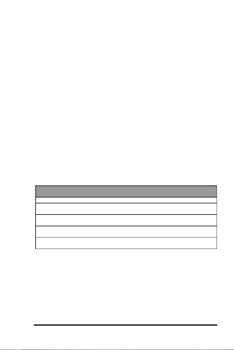
NRAID
Disk Spanning
Minimum
Disks required
Capacity N
Redundancy No
NRAID
+
+
+
1
=
Logical
Drive
2 GB Hard Drive
3 GB Hard Drive
1 GB Hard Drive
2 GB Hard Drive
2 + 3 + 1 + 2 = 8 GB Logical Drive
NRAID stands for Non-RAID. The capacity of all the drives are
combined to become one logical drive (no block striping). In other
words, the capacity of the logical drive is the total capacity of the
physical drives. NRAID does not provide data redundancy.
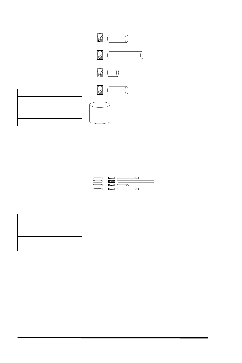
= 2 GB Hard Drive
JBOD
Single-drive Control
2 GB
Logical Drive
3 GB
Logical Drive
1 GB
Logical Drive
2 GB
Logical Drive
=
=
=
1 GB Hard Drive
3 GB Hard Drive
2 GB Hard Drive
Minimum
Disks required
Capacity 1
Redundancy No
JBOD
1
JBOD stands for Just a Bunch of Drives. The controller treats each
drive as a stand-alone disk, therefore each drive is an independent
logical drive. JBOD does not provide data redundancy.
3-2
ASUS PCI-DA2200 User’s Manual
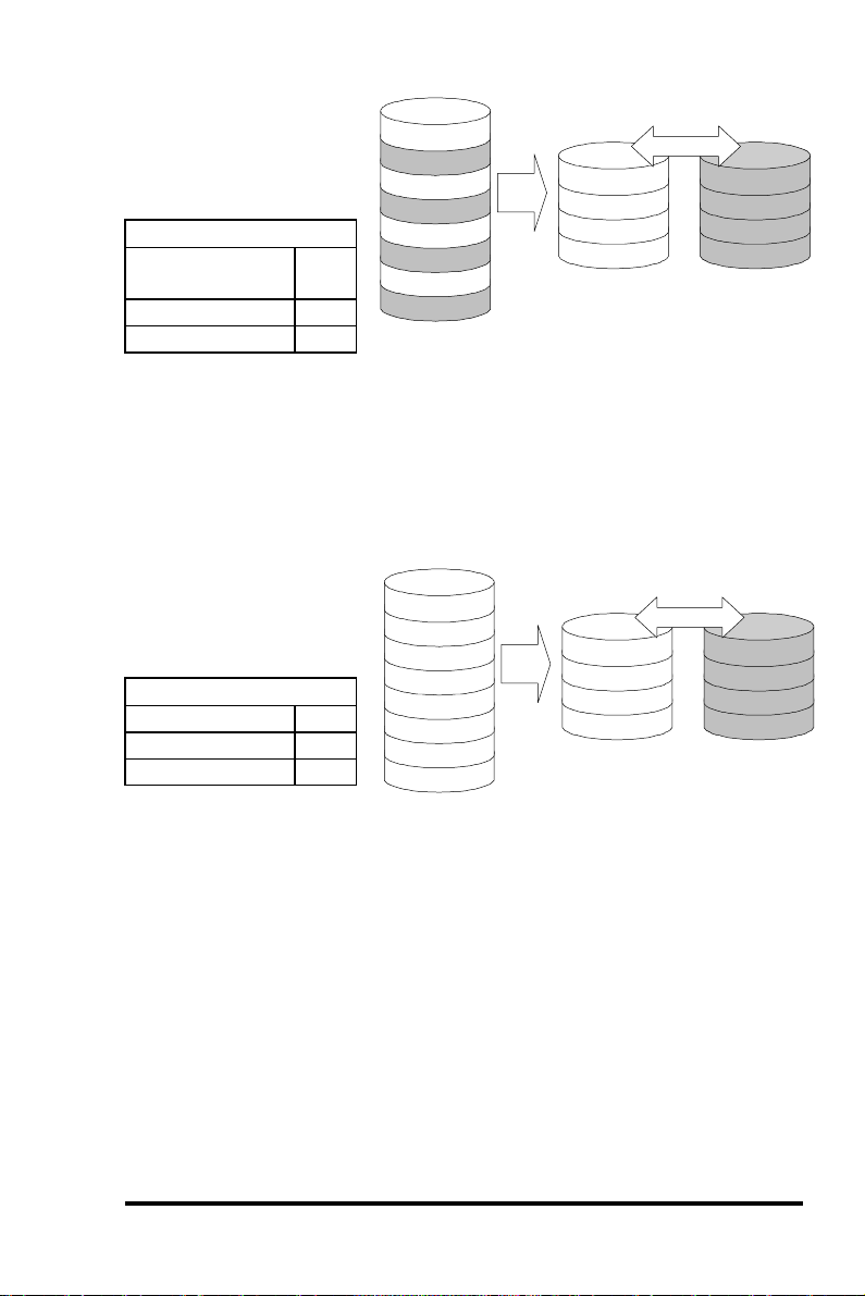
RAID 0
Disk Striping
Minimum
Disks required
Capacity N
Redundancy No
RAID 0
2
Logical Drive
Block 1
Block 2
Block 3
Block 4
Block 5
Block 6
Block 7
Block 8
.
.
Physical Disks
Block 1
Block 3
Block 5
Block 7
.
.
Striping
Block 2
Block 4
Block 6
Block 8
.
.
RAID 0 provides the highest performance but no redundancy. Data
in the logical drive is striped (distributed) across several physical
drives.
RAID 1
Disk Mirroring
Disks required 2
Capacity N/2
Redundancy Yes
RAID 1
Logical Drive
Block 1
Block 2
Block 3
Block 4
Block 5
Block 6
Block 7
Block 8
.
.
Physical Disks
Block 1
Block 2
Block 3
Block 4
.
.
Mirroring
Mirror 1
Mirror 2
Mirror 3
Mirror 4
.
.
RAID 1 mirrors the
data stored in one hard drive to another. RAID 1 can only be
performed with two hard drives. If there are more than two hard
drives, RAID (0+1) will be performed automatically.
ASUS PCI-DA2200 User’s Manual
3-3
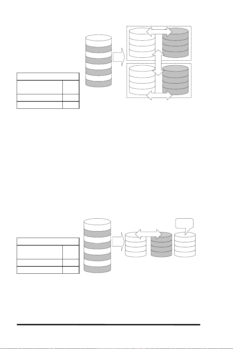
RAID (0+1)
Disk Striping with
Mirroring
RAID (0+1)
Minimum
Disks required
Capacity N/2
Redundancy Yes
Logical Drive
Block 1
Block 2
Block 3
Block 4
Block 5
Block 6
Block 7
4
Block 8
.
.
Physical Disks
Block 1
Block 3
Block 5
Block 7
.
.
Mirror 1
Mirror 3
Mirror 5
Mirror 7
.
.
Striping
Mirror
Striping
Block 2
Block 4
Block 6
Block 8
.
.
Mirror 2
Mirror 4
Mirror 6
Mirror 8
.
.
RAID (0+1) combines RAID 0 and RAID 1 - Mirroring and Striping.
RAID (0+1) allows multiple drive failure because of the full
redundancy of the hard drives. If there are more than two hard
drives assigned to perform RAID 1, RAID (0+1) will be performed
automatically.
IMPORTANT:
“RAID (0+1)” will not appear in the list of RAID levels supported by the
controller. If you wish to perform RAID 1, the controller will determine
whether to perform RAID 1 or RAID (0+1). This will depend on the drive
number that has been selected for the logical drive.
RAID 3
Disk Striping with
Logical Drive Physical Disks
Dedicated Parity Disk
Minimum
Disks required
Capacity N-1
Redundancy Yes
RAID 3
3
Block 1
Block 2
Block 3
Block 4
Block 5
Block 6
Block 7
Block 8
.
.
Block 1
Block 3
Block 5
Block 7
.
.
Striping
Block 2
Block 4
Block 6
Block 8
.
.
RAID 3 performs Block Striping with Dedicated Parity. One drive
member is dedicated to storing the parity data. When a drive
member fails, the controller can recover/regenerate the lost data of
the failed drive from the dedicated parity drive.
3-4
ASUS PCI-DA2200 User’s Manual
Dedicated
Parity
Parity (1,2)
Parity (3,4)
Parity (5,6)
Parity (7,8)
.
.
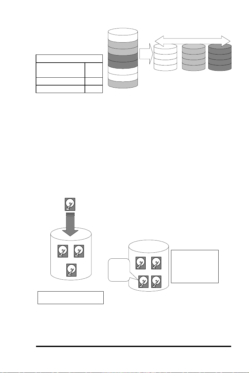
RAID 5
Logical Drive Physical Disks
Striping with
Interspersed Parity
Minimum
Disks required
Capacity N-1
Redundancy Yes
RAID 5
3
Block 1
Block 2
Block 3
Block 4
Block 5
Block 6
Block 7
Block 8
.
.
Striping + non-dedicated Parity
Block 1
Parity (3,4)
Block 6
Block 7
.
.
Block 2
Block 3
Parity (5,6)
Block 8
.
.
Parity (1,2)
Parity (7,8)
Block 4
Block 5
.
.
RAID 5 is similar to RAID 3 but the parity data is not stored in one
dedicated hard drive. Parity information is interspersed across the
drive array. In the event of a failure, the controller can
recover/regenerate the lost data of the failed drive from the other
surviving drives.
3.2 Drive Failure Management
3.2.1 Global and Local Spare Drive
Local Spare Drive
Local Spare Drive is a standby drive
assigned to serve one specified logical
LS
drive. When a member drive of this
specified logical drive fails, the Local
Spare Drive becomes a member drive and
automatically starts to rebuild.
1 2
Logical Drive
Assigns one Local Spare
Drive to a logical drive
Local
3
Spare
Drive
1 2
X
LS
Logical Drive
When one member
drive fails, the Local
Spare Drive joins the
logical drive and
automatically starts
to rebuild.
3
Global Spare Drive does not only serve one specified logical drive.
When a member drive from any of the logical drive fails, the Global
ASUS PCI-DA2200 User’s Manual
3-5
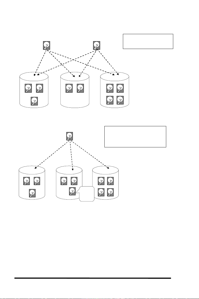
Spare Drive will join that logical drive and automatically starts to
rebuild.
Global Spare Drive
1 2
Logical Drive 0
1 2
Logical Drive 0
3
GS
3
Global Spare Drive
1 2
Logical Drive 1
Global Spare Drive
GS
1 2
X
GS
Logical Drive 1
Global
Spare
Drive
Global Spare Drives serve
any logical drives.
GS
1 2
34
Logical Drive 2
When a member drive from any
logical drive fails, the Global Spare
Drive joins that logical drive and
automatically starts to rebuild.
1 2
34
Logical Drive 2
The ASUS PCI-DA2200 RAID controller provides both Local Spare
Drive and Global Spare Drive functions. On certain occasions,
applying these two functions together will better fit various needs.
Take note though that the Local Spare Drive always has higher
priority than the Global Spare Drive.
In the example shown on the next page, the member drives in Logical
Drive 0 are 9 GB drives, and the members in Logical Drives 1 and 2
are all 4 GB drives. It is not possible for the 4 GB Global Spare Drive
to join Logical Drive 0 because of its insufficient capacity. However
3-6
ASUS PCI-DA2200 User’s Manual
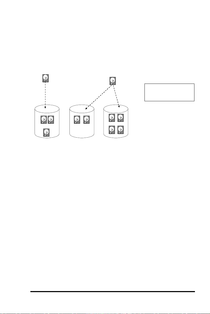
using a 9GB drive as the Global Spare drive for a failed drive that
comes from Logical Drive 1 or 2 will bring huge amount of excess
capacity since these logical drives require 4 GB only. In the settings
below, the 9 GB Local Spare Drive will aid Logical Drive 0 once a
drive in this logical drive failed. If the failed drive is in Logical Drive
1 or 2, the 4 GB Global Spare drive will immediately give aid to the
failed drive.
Local Spare Drive
LS
1 2
(9GB)(9GB)
3
(9GB)
Logical Drive 0
1 2
(4GB) (4GB)
Logical Drive 1
Global Spare Drive
GS(9GB)
(4GB)
1 2
(4GB) (4GB)
34
(4GB) (4GB)
Logical Drive 2
Local Spare Drive always
has higher priority than
Global Spare Drive.
3.2.2 Identifying Drives
Assuming there is a failed drive in the RAID 5 logical drive, make it a
point to replace the failed drive with a new drive to keep the logical
drive working.
When trying to remove a failed drive and you mistakenly removed
the wrong drive, you will no longer be able to read/write the logical
drive because the two drives may have already failed.
To prevent this from happening, the controller provides an easy way
of identifying for the failed drive. That is, the read/write LED of the
failed hard drive will light. This LED will prevent you from
removing the wrong drive, and is also helpful when locating for a
drive.
ASUS PCI-DA2200 User’s Manual
3-7
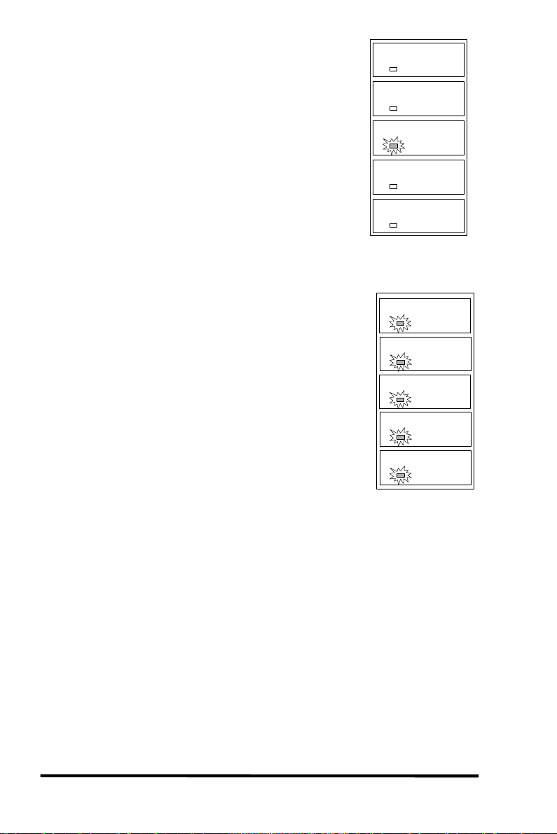
Flash Selected SCSI Drive
The Read/Write LED of the drive you selected
will light steadily for about one minute.
Flash All SCSI Drives
The Read/Write LED of all connected drives will
light for about one minute. If the LED of the
defective drive did not light on the “Flash
Selected SCSI Drive” function, use “Flash All
SCSI Drives”. The “Flash All SCSI Drives”
function will light LEDs of all the drives except
the defective one.
3.2.3 Automatic Rebuild and Manual
R/W LED
R/W LED
LED Steadily ON
R/W LED
R/W LED
LED Steadily ON
LED Steadily ON
LED Steadily ON
LED Steadily ON
LED Steadily ON
3-8
ASUS PCI-DA2200 User’s Manual
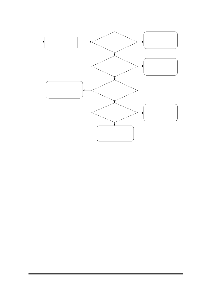
Rebuild
Automatic Rebuild
One member drive
fails in logical drive
Waiting for spare
drive to be added
or manual rebuild
assigned to logical
global spare drive
assigned to logical
No
Auto-Detect Failure
Drive Swap Check Time”
Keep detecting if drive
has been swapped or
spare drive has been
Any
local spare drive
drive?
No
Any
drive?
No
“Periodic
enabled?
Yes
Has the
failed drive been
swapped?
No
added
Yes
Yes
Yes
Rebuild using the
local spare drive
Rebuild using the
global spare drive
Rebuild using the
swapped drive
When a member drive in the logical drive failed, the controller will
first check whether there is a Local Spare Drive assigned to this
logical drive. If yes, it will automatically start to rebuild.
If there is no Local Spare Drive available, the controller will search
for a Global Spare Drive. If there is a Global Spare Drive, it will
automatically rebuild the logical drive.
If neither a Local Spare Drive nor a Global Spare Drive is available,
and the “Periodic Auto-Detect Failure Drive Swap Check Time” is
“Disabled,” the controller will not try to rebuild unless the user
applies a forced manual rebuild.
When the “Periodic Auto-Detect Failure Drive Swap Check Time” is
enabled (i.e., a check time interval has been selected), the controller
will detect whether or not the failed drive has been swapped (by
checking the failed drive’s channel/ID). Once the failed drive has
been swapped, the rebuild will begin immediately.
ASUS PCI-DA2200 User’s Manual
3-9
If the failed drive is not swapped but a local spare drive is added to
rebuild
been replaced?
the logical drive, rebuilding will begin with the spare drive.
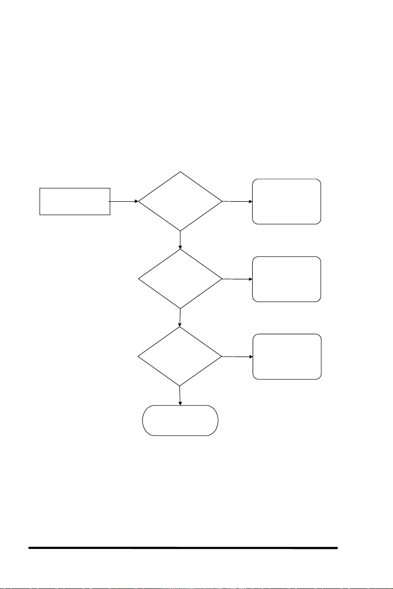
Manual Rebuild
When a user applies forced-manual rebuild, the controller will first
check whether there is any Local Spare Drive assigned to this logical
drive. If yes, it will automatically start to rebuild.
If there is no Local Spare Drive available, the controller will search
for a Global Spare Drive. If there is a Global Spare Drive, it will
automatically rebuild the logical drive.
User applies
forced-manual
Any
Local Spare Drive
assigned to this
logical drive?
No
Any
Global Spare Drive
assigned to this
logical drive?
No
Has the failed drive
No
Wait for
manual rebuild
Yes
Yes
Yes
Rebuild using the
Local Spare Drive
Rebuild using the
Global Spare Drive
Rebuild using the
replaced drive
If neither a Local Spare Drive nor a Global Spare Drive is available,
the controller will detect the SCSI channel and ID of the failed drive.
Once the failed drive has been replaced by a new drive/used drive, it
starts to rebuild using the replaced drive. If there is no available
drive for rebuilding, the controller will not try to rebuild again until
the user applies another forced-manual rebuild.
3-10
ASUS PCI-DA2200 User’s Manual

3.2.4 Concurrent Rebuild in RAID (0+1)
RAID (0+1) allows multiple drive failure and concurrent multiple
drive rebuild. Newly replaced drives must be scanned and set as
Local Spare Drives. These drives will be rebuilt at the same time (you
do not need to repeat the rebuilding process for each drive).
3.3 Disk Array Parameters
3.3.1 Rebuild Priority
Rebuilding time will depend on the capacity of the logical drive. The
ASUS PCI-DA2200 RAID controller provides background rebuilding
ability. Meaning, the controller is able to serve other I/O requests
while rebuilding the logical drives. The rebuilding process is totally
transparent to the host computer or the operating system.
The background rebuild process has four priority options:
• Low
• Normal
• Improved
• High
The default priority is “Low” which uses the controller’s minimum
resources to rebuild. Choosing “Normal” or “Improved” will
speedup the rebuilding process and choosing “High” will use the
controller’s maximum resources to complete the rebuilding process
at the shortest time.
Rebuild priority can be configured through either the Text RAID
Manager or the GUI RAID Manager.
3.3.2 Verify-after-Write
The controller has the ability to force the hard drives to verify after
data has been written to the media of the HDD. There are three
selectable methods:
• Verification on LD Initialization Writes
Performs Verify-after-Write while initializing the logical drive.
• Verification on LD Rebuild Writes
Performs Verify-after-Write during the rebuilding process.
• Verification on LD Normal Drive Writes
Performs Verify-after-Write during normal I/O requests.
ASUS PCI-DA2200 User’s Manual
3-11

Each method can be enabled or disabled individually. Hard drives
will perform Verify-after-Write according to the selected method.
3-12
ASUS PCI-DA2200 User’s Manual

ASUS PCI-DA2200 User’s Manual
3-13

IMPORTANT:
The “Verification on LD Normal Drive Writes” method will affect “write”
performance during normal use.
3.4 Cache Parameters
3.4.1 Optimization for Sequential or Random I/O
When using RAID with applications such as video or image oriented
applications, the application reads/writes from the drive using largeblock, sequential files instead of small-block, random access files. The
ASUS PCI-DA2200 RAID controller provides the options to optimize
for large-sequential I/O or optimize for small-random I/O access.
“Optimization for Sequential I/O” provides a larger – 128K – stripe
size (or “block” size, also known as “chunk” size) than does
“Optimization for Random I/O” (with a size of 32K). A lot of the
controller’s internal parameters will also be changed to optimize for
sequential or random I/O. The change will take effect after the
controller reboots.
If the existing logical drives were built with “Optimization for
Random I/O”, these logical drives will not read/write when using
“Optimization for Sequential I/O” (shows "INVALID") and vice
versa because the stripe size is different. Change it back to the
original setting and reset the controller to make available the logical
drive data again.
3-14
ASUS PCI-DA2200 User’s Manual

ASUS PCI-DA2200 User’s Manual
3-15

IMPORTANT:
Changing the setting to “Optimization for Sequential I/O” or
“Optimization for Random I/O” should be performed only when no logical
drive exist. Otherwise, you will not be able to access the data in the logical
drive later on.
3.5 Drive-Side SCSI Parameters
3.5.1 SCSI Motor Spin-up
When the power supply is unable to provide sufficient current for all
the hard drives and controllers that are powered-up at the same time,
spinning-up the hard drives serially is one of the best way of
consuming lower power-up current.
By default, all hard drives will spin-up when powered-on. These
hard drives can be configured so that all of them will not spin-up at
power-on. There are 3 methods of spinning-up the hard drive’s
motor: Spin-up at power-on, Spin-up serially in random sequence or
Spin-up by SCSI command. Please refer to the hard drive’s user’s
manual for instructions on configuring the hard drive using the
“Spin-up by SCSI command”. The procedure for each brand/model
of hard drive should vary.
Configure all the hard drives as above and enable “SCSI Motor SpinUp” in Drive-Side SCSI Parameters. Power off all hard drives and
controller, and power them on again. All the hard drives will not
spin-up at this time. The controller will then spin-up the hard drives
one by one at four seconds interval.
3-16
ASUS PCI-DA2200 User’s Manual

ASUS PCI-DA2200 User’s Manual
3-17

IMPORTANT:
If the drives are configured as “Delay Motor Spin-up” or “Motor Spin-up
in Random Sequence,” some of these drives may not be ready yet for the
controller to access when the system powers up. Increase the disk access
delay time so that the controller will wait a longer time for the drive to be
ready.
3.5.2 SCSI Reset at Power Up
By default, when the controller is powered up, it will send a SCSI bus
reset command to the SCSI bus. When disabled, it will not send a
SCSI bus reset command on the next power-up.
When connecting dual host computers to the same SCSI bus, the SCSI
bus reset will interrupt all the read/write requests that are being
performed. This may cause some operating systems or host
computers to act abnormally. Disable the “SCSI Reset at Power-up”
to avoid this situation.
3.5.3 Disk Access Delay Time
Sets the delay time before the controller tries to access the hard drives after
power-on. The default is 15 seconds.
3.5.4 SCSI I/O Timeout
The “SCSI I/O Timeout” is the time interval that the controller waits
for a drive to respond. If the controller attempts to read data from or
write data to a drive, but the drive does not respond within the SCSI
I/O timout value, the drive will be judged to be a failed drive.
When the drive itself detects a media error while reading from the
drive platter, it will retry the previous reading or recalibrate the
head. When the drive has encountered a bad block on the media, it
has to reassign the bad block to another spare block. However, all of
this takes time. The time to perform these operations can vary
between different brands and models of drives.
During SCSI bus arbitration, a device with higher priority can utilize
the bus first. A device with lower priority will sometimes get a SCSI
I/O timeout when higher priority devices keep utilizing the bus.
The default setting for “SCSI I/O Timeout” is 7 seconds. It is highly
recommended not to change this setting. Setting the timeout to a
lower value will cause the controller to judge a drive as failed a drive
3-18
ASUS PCI-DA2200 User’s Manual

is still retrying or while a drive is unable to arbitrate the SCSI bus.
Setting the timeout to a greater value will cause the controller to
keep waiting for a drive, and it may sometimes cause a host timeout.
3.5.5 Maximum Tag Count
The maximum number of tags that can be sent to each drive at the
same time. A drive has a built-in cache that is used to sort all of the
I/O requests (“tags”) which are sent to the drive, allowing the drive
to finish the requests faster. The cache size and maximum number of
tags varies between different brands and models of drive. Using the
default setting – “32” – is highly recommended. Changing the
maximum tag count to “Disable” will cause the internal cache of the
drive to be ignored (i.e., not used).
3.5.6 Periodic Drive Check Time
The “Periodic Drive Check Time” is an interval for the controller to
check all of the drives that were on the SCSI bus at controller startup
(a list of all the drives that were detected can be seen under “View
and Edit SCSI Drives”). The default value is “Disabled”. “Disabled”
means that if a drive is removed from the bus, the controller will not
be able to know – so long as no host accesses that drive. Changing the
check time to any other value allows the controller to check – at the
selected interval – all of the drives that are listed under “View and
Edit SCSI Drives.” If any drive is then removed, the controller will be
able to know – even if no host accesses that drive.
3.5.7 SAF-TE Enclosure Monitoring
What is SAF-TE?
SAF-TE stands for SCSI Accessed Fault-Tolerant Enclosures. It is an
enclosure management technology that uses the SCSI bus to interact
with the controller. A SAF-TE-compliant enclosure monitors the fan
temperature, power supply, UPS and also provides drive status
LED’s.
How does it work?
The SAF-TE device, which is often a back-plane within a drive-bay
enclosure, must occupy a connector on one of the drive channels’
SCSI cables. The presence of a SAF-TE device will be detected and its
presence will be displayed in the BIOS configuration utility, Text
RAID Manager and the GUI RAID Manager programs. The RAID
ASUS PCI-DA2200 User’s Manual
3-19
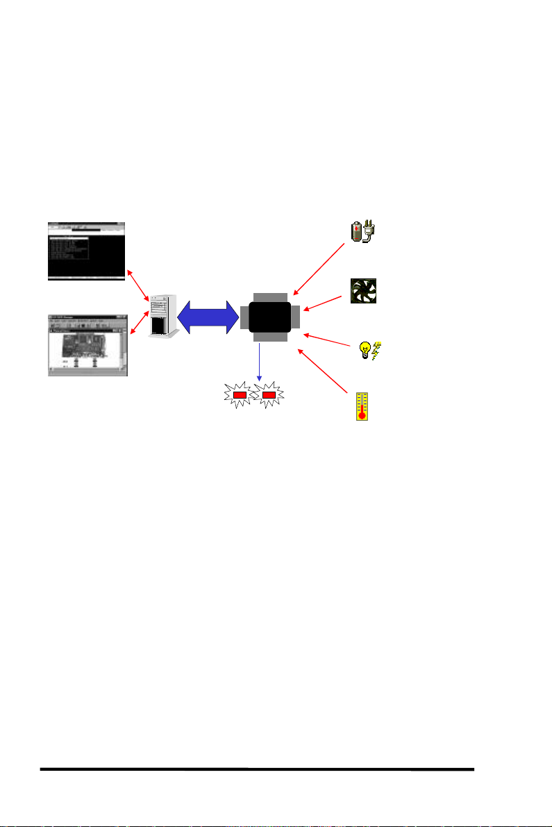
controller communicates with the SAF-TE enclosure with standard
SCSI commands, polling the device in order to get SAF-TE
information.
The default value for “Periodic SAF-TE Device Check Time” is
“Disabled”. If the enclosure does have a SAF-TE device and features,
enable the controller to poll the device by selecting a time interval.
The RAID controller will then check the SAF-TE device status at that
interval.
UPS Failure
Signal Input
Cooling Fan
Failure
Signal Input
Power Supply
Failure
Signal Input
Temperature Alert
Signal Input
Text RAID Manager
error alert
GUI RAID Manager
error alert
SAF-TE Support
PCI-to-SCSI
System with
RAID controller
installed
SAF-TE
Chipset
Drive Status
Indicators
• The SAF-TE chipset connects to the drive channel of the
controller together with the other SCSI drives.
3.5.8 Periodic Auto-Detect Failure Drive
Swap Check Time
The “Drive-Swap Check Time” is the interval at which the controller
checks to see whether a failed drive has been swapped. When a
logical drive’s member drive fails, the controller will detect the failed
drive (at the selected time interval). Once the failed drive has been
swapped with a drive that has adequate capacity to rebuild the
logical drive, the rebuild will begin automatically.
The default setting is “Disabled,” meaning that that the controller
will not Auto-Detect the swap of a failed drive. To enable this
feature, select a time interval.
3-20
ASUS PCI-DA2200 User’s Manual
 Loading...