

Page 1

P9A-I Series
Motherboard
Page 2

E9515
Second Edition
June 2014
Copyright © 2014 ASUSTeK COMPUTER INC. All Rights Reserved.
No part of this manual, including the products and software described in it, may be reproduced, transmitted,
transcribed, stored in a retrieval system, or translated into any language in any form or by any means,
except documentation kept by the purchaser for backup purposes, without the express written permission
of ASUSTeK COMPUTER INC. (“ASUS”).
Product warranty or service will not be extended if: (1) the product is repaired, modied or altered, unless
such repair, modication of alteration is authorized in writing by ASUS; or (2) the serial number of the
product is defaced or missing.
ASUS PROVIDES THIS MANUAL “AS IS” WITHOUT WARRANTY OF ANY KIND, EITHER EXPRESS
OR IMPLIED, INCLUDING BUT NOT LIMITED TO THE IMPLIED WARRANTIES OR CONDITIONS OF
MERCHANTABILITY OR FITNESS FOR A PARTICULAR PURPOSE. IN NO EVENT SHALL ASUS, ITS
DIRECTORS, OFFICERS, EMPLOYEES OR AGENTS BE LIABLE FOR ANY INDIRECT, SPECIAL,
INCIDENTAL, OR CONSEQUENTIAL DAMAGES (INCLUDING DAMAGES FOR LOSS OF PROFITS,
LOSS OF BUSINESS, LOSS OF USE OR DATA, INTERRUPTION OF BUSINESS AND THE LIKE),
EVEN IF ASUS HAS BEEN ADVISED OF THE POSSIBILITY OF SUCH DAMAGES ARISING FROM ANY
DEFECT OR ERROR IN THIS MANUAL OR PRODUCT.
SPECIFICATIONS AND INFORMATION CONTAINED IN THIS MANUAL ARE FURNISHED FOR
INFORMATIONAL USE ONLY, AND ARE SUBJECT TO CHANGE AT ANY TIME WITHOUT NOTICE,
AND SHOULD NOT BE CONSTRUED AS A COMMITMENT BY ASUS. ASUS ASSUMES NO
RESPONSIBILITY OR LIABILITY FOR ANY ERRORS OR INACCURACIES THAT MAY APPEAR IN THIS
MANUAL, INCLUDING THE PRODUCTS AND SOFTWARE DESCRIBED IN IT.
Products and corporate names appearing in this manual may or may not be registered trademarks or
copyrights of their respective companies, and are used only for identication or explanation and to the
owners’ benet, without intent to infringe.
ii
Page 3

Contents
Notices ....................................................................................................................... vi
Safety information ..................................................................................................... vii
About this guide ......................................................................................................... ix
P9A-I Series Specifications Summary...................................................................... xi
Chapter 1: Product Introduction
1.1 Welcome! .................................................................................................... 1-3
1.2 Package contents ......................................................................................1-3
1.3 Serial number label .................................................................................... 1-3
1.4 Special features..........................................................................................1-3
1.4.1 Product highlights........................................................................1-3
1.4.2 Innovative ASUS features ...........................................................1-4
Chapter 2: Hardware Information
2.1 Before you proceed ...................................................................................2-3
2.2 Motherboard overview ............................................................................... 2-4
2.2.1 Placement direction.....................................................................2-4
2.2.2 Screw holes.................................................................................2-4
2.2.3 Motherboard layout .....................................................................2-5
2.2.4 Layout contents ...........................................................................2-6
2.3 Central Processing Unit (CPU) .................................................................2-8
2.4 System memory .........................................................................................2-8
2.4.1 Overview ..................................................................................... 2-8
2.4.2 Memory Congurations ...............................................................2-8
2.4.3 Installing a DIMM on a single clip DIMM socket..........................2-9
2.5 Expansion slots ........................................................................................2-10
2.5.1 Installing an expansion card......................................................2-10
2.5.2 Conguring an expansion card .................................................2-10
2.5.3 Interrupt assignments................................................................2-11
2.5.4 PCI Express x8 slot (x4 Gen2 link) ...........................................2-11
2.6 Onboard LEDs .......................................................................................... 2-12
2.7 Jumpers .................................................................................................... 2-13
2.8 Connectors ............................................................................................... 2-15
2.8.1 Rear panel connectors ..............................................................2-15
2.8.2 Internal connectors....................................................................2-16
Chapter 3: Powering Up
3.1 Starting up for the first time ...................................................................... 3-3
3.2 Powering off the computer ........................................................................3-4
3.2.1 Using the OS shut down function ................................................3-4
3.2.2 Using the dual function power switch ..........................................3-4
iii
Page 4

Contents
Chapter 4: BIOS setup
4.1 Managing and updating your BIOS .......................................................... 4-3
4.1.1 ASUS CrashFree BIOS 3 utility...................................................4-3
4.1.2 ASUS EzFlash Utility...................................................................4-4
4.1.3 BUPDATER utility .......................................................................4-5
4.2 BIOS setup program .................................................................................. 4-7
4.2.1 BIOS menu screen ......................................................................4-8
4.2.2 Menu bar .....................................................................................4-8
4.2.3 Menu items..................................................................................4-9
4.2.4 Submenu items ...........................................................................4-9
4.2.5 Navigation keys ...........................................................................4-9
4.2.6 General help................................................................................4-9
4.2.7 Conguration elds .....................................................................4-9
4.2.8 Pop-up window............................................................................4-9
4.2.9 Scroll bar .....................................................................................4-9
4.3 Main menu ................................................................................................4-10
4.3.1 System Language [English] ......................................................4-10
4.3.2 System Date .............................................................................4-10
4.3.3 System Time .............................................................................4-10
4.4 Advanced menu .......................................................................................4-11
4.4.1 Enable CRID [Disabled] ............................................................4-11
4.4.2 ACPI Settings ............................................................................4-12
4.4.3 NCT6779D Super IO Conguration ..........................................4-13
4.4.4 Serial Port Console Redirection ................................................4-14
4.4.5 Onboard LAN I354 Conguration ..............................................4-16
4.4.6 APM .......................................................................................... 4-17
4.4.7 PCI Subsystem Settings ........................................................... 4-18
4.4.8 Network Stack Conguration.....................................................4-22
4.4.9 CSM Conguration .................................................................... 4-22
4.4.10 Trusted Computing....................................................................4-24
4.4.11 USB Conguration .................................................................... 4-24
4.4.12 iSCSI Conguration...................................................................4-26
4.4.13 Intel(R) Ethernet Connection I354............................................. 4-26
4.4.14 Driver Health ............................................................................. 4-27
4.5 IntelRCSetup menu .................................................................................. 4-28
4.5.1 Processor Conguration............................................................4-29
4.5.2 Thermal Conguration...............................................................4-32
4.5.3 USB Conguration ....................................................................4-36
4.5.4 CK420 Conguration .................................................................4-36
4.5.5 Network Conguration...............................................................4-37
iv
Page 5

Contents
4.5.6 North Bridge Chipset Conguration ..........................................4-37
4.5.7 Wake On Lan Conguration ......................................................4-44
4.5.8 South Bridge Chipset Conguration ..........................................4-44
4.5.9 System Event Log .....................................................................4-48
4.6 Server Mgmt menu ................................................................................... 4-50
4.6.1 System Event Log .....................................................................4-51
4.6.2 View FRU information ...............................................................4-52
4.6.3 BMC network conguration .......................................................4-52
4.6.4 View System Event Log ............................................................4-53
4.6.5 IPv6 BMC Network Conguration .............................................4-53
4.7 Event Logs menu ..................................................................................... 4-55
4.7.1 Change Smbios Event Log Settings .........................................4-55
4.7.2 View Smbios Event Log ............................................................4-56
4.8 Security ..................................................................................................... 4-57
4.9 Boot menu ................................................................................................4-60
4.10 Monitor menu ........................................................................................... 4-61
4.11 Tool menu ................................................................................................. 4-62
4.12 Exit menu .................................................................................................. 4-62
Chapter 5: Driver installation
5.1 Management applications and utilities installation ................................ 5-3
5.2 Running the Support DVD ........................................................................ 5-3
5.3 Installing the LAN driver ..........................................................................5-11
5.4 Installing the VGA driver .........................................................................5-16
5.5 Installing the Intel® I354 Gigabit Adapters driver .................................. 5-19
Appendix A: Reference Information
A.1 Block diagram ........................................................................................... A-3
ASUS contact information .......................................................................................... 1
v
Page 6

Notices
Federal Communications Commission Statement
This device complies with Part 15 of the FCC Rules. Operation is subject to the following two
conditions:
• This device may not cause harmful interference, and
• This device must accept any interference received including interference that may cause
undesired operation.
This equipment has been tested and found to comply with the limits for a Class B digital
device, pursuant to Part 15 of the FCC Rules. These limits are designed to provide
reasonable protection against harmful interference in a residential installation. This equipment
generates, uses and can radiate radio frequency energy and, if not installed and used
in accordance with manufacturer’s instructions, may cause harmful interference to radio
communications. However, there is no guarantee that interference will not occur in a particular
installation. If this equipment does cause harmful interference to radio or television reception,
which can be determined by turning the equipment off and on, the user is encouraged to try
to correct the interference by one or more of the following measures:
• Reorient or relocate the receiving antenna.
• Increase the separation between the equipment and receiver.
• Connect the equipment to an outlet on a circuit different from that to which the receiver is
connected.
• Consult the dealer or an experienced radio/TV technician for help.
The use of shielded cables for connection of the monitor to the graphics card is required
to assure compliance with FCC regulations. Changes or modications to this unit not
expressly approved by the party responsible for compliance could void the user’s authority
to operate this equipment.
Canadian Department of Communications Statement
This digital apparatus does not exceed the Class B limits for radio noise emissions from
digital apparatus set out in the Radio Interference Regulations of the Canadian Department of
Communications.
This class B digital apparatus complies with Canadian ICES-003.
REACH
Complying with the REACH (Registration, Evaluation, Authorization, and Restriction of
Chemicals) regulatory framework, we publish the chemical substances in our products at
ASUS REACH website at http://csr.asus.com/english/REACH.htm.
vi
Page 7

Safety information
Electrical safety
• To prevent electrical shock hazard, disconnect the power cable from the electrical outlet
before relocating the system.
• When adding or removing devices to or from the system, ensure that the power cables
for the devices are unplugged before the signal cables are connected. If possible,
disconnect all power cables from the existing system before you add a device.
• Before connecting or removing signal cables from the motherboard, ensure that all power
cables are unplugged.
• Seek professional assistance before using an adapter or extension cord. These devices
could interrupt the grounding circuit.
• Make sure that your power supply is set to the correct voltage in your area. If you are
not sure about the voltage of the electrical outlet you are using, contact your local power
company.
• If the power supply is broken, do not try to x it by yourself. Contact a qualied service
technician or your retailer.
Operation safety
• Before installing the motherboard and adding devices on it, carefully read all the manuals
that came with the package.
• Before using the product, make sure all cables are correctly connected and the power
cables are not damaged. If you detect any damage, contact your dealer immediately.
• To avoid short circuits, keep paper clips, screws, and staples away from connectors,
slots, sockets and circuitry.
• Avoid dust, humidity, and temperature extremes. Do not place the product in any area
where it may become wet.
• Place the product on a stable surface.
• If you encounter technical problems with the product, contact a qualied service
technician or your retailer.
DO NOT
throw the motherboard in municipal waste. This product has been designed to
enable proper reuse of parts and recycling. This symbol of the crossed out wheeled bin
indicates that the product (electrical and electronic equipment) should not be placed in
municipal waste. Check local regulations for disposal of electronic products.
DO NOT
throw the mercury-containing button cell battery in municipal waste. This symbol
of the crossed out wheeled bin indicates that the battery should not be placed in municipal
waste.
vii
Page 8

Australia statement notice
From 1 January 2012 updated warranties apply to all ASUS products, consistent with
the Australian Consumer Law. For the latest product warranty details please visit http://
support.asus.com. Our goods come with guarantees that cannot be excluded under the
Australian Consumer Law. You are entitled to a replacement or refund for a major failure and
compensation for any other reasonably foreseeable loss or damage. You are also entitled
to have the goods repaired or replaced if the goods fail to be of acceptable quality and the
failure does not amount to a major failure.
If you require assistance please call ASUS Customer Service 1300 2787 88 or visit us at
http://support.asus.com
viii
Page 9

About this guide
This user guide contains the information you need when installing and conguring the
motherboard.
How this guide is organized
This user guide contains the following parts:
• Chapter1:Productintroduction
This chapter describes the features of the motherboard and the new technologies it
supports.
• Chapter2:Hardwareinformation
This chapter lists the hardware setup procedures that you have to perform when
installing system components. It includes description of the switches, jumpers, and
connectors on the motherboard.
• Chapter3:Poweringup
This chapter describes the power up sequence and ways of shutting down the system.
• Chapter4:BIOSsetup
This chapter tells how to change system settings through the BIOS Setup menus.
Detailed descriptions of the BIOS parameters are also provided.
• Chapter5:Driverinstallation
This chapter provides instructions for installing the necessary drivers for different
system components.
• Appendix:Referenceinformation
This appendix includes additional information that you may refer to when conguring
the motherboard.
Where to find more information
Refer to the following sources for additional information and for product and software updates.
1. ASUS websites
The ASUS website provides updated information on ASUS hardware and software
products. Refer to the ASUS contact information.
2. Optional documentation
Your product package may include optional documentation, such as warranty yers,
that may have been added by your dealer. These documents are not part of the
standard package.
ix
Page 10

Conventions used in this guide
To ensure that you perform certain tasks properly, take note of the following symbols used
throughout this manual.
DANGER/WARNING: Information to prevent injury to yourself when trying to
complete a task.
CAUTION: Information to prevent damage to the components when trying to
complete a task
IMPORTANT: Instructions that you MUST follow to complete a task.
.
NOTE: Tips and additional information to help you complete a task.
Typography
Bold text Indicates a menu or an item to select.
Italics
<Key> Keys enclosed in the less-than and greater-than sign means
<Key1> + <Key2> + <Key3> If you must press two or more keys simultaneously, the key
Command
Used to emphasize a word or a phrase.
that you must press the enclosed key.
Example: <Enter> means that you must press the Enter or
Return key.
names are linked with a plus sign (+).
Example: <Ctrl> + <Alt> + <Del>
Means that you must type the command exactly as shown,
then supply the required item or value enclosed in brackets.
Example: At DOS prompt, type the command line:
format A:/S
x
Page 11

P9A-I Series Specifications Summary
Model Name P9A-I/C2750/SAS/4L P9A-I/C2550/SAS/4L P9A-I/C2550/4L
Processor Support / System Bus
Form Factor
ASUS Features
Memory
Expansion
Slots (follow
SSI Location
number)
Storage
Networking
Graphic
Onboard I/O
Connectors
Rear I/O
Connectors
Management
Solution
Monitoring
Fan Speed Control
ASWM Enterprise
Total Slots
Capacity
Memory Type
Total PCI//PCI-X/
PCI-E Slots
Slot Location 7
SATA Controller
SAS Controller
LAN
VGA
PSU Connector
Fan Header
Chassis Intruder
Front LAN LED
Serial Port Header
SATA DOM Power
Connector
M.2 Connector
External USB Port
VGA Port
RJ-45
Software
Out of Band
Remote
Management
CPU Temperature
FAN RPM
Regulatory Compliance
Intel® Atom® C-Series FCBGA processor (Avoton)
C2750 C2550
Mini-ITX, 6.7 in. x 6.7 in.
2 (2 Channels)
Maximum up to 32GB
DDR3 1333/1600 ECC/Non-ECC UDIMM
1
1 x PCI-E x8 (x4 Gen2 link)
2 x SATA 6Gb/s ports (1 for SATA 6Gb/s or M.2 connector)
4 x MiniSAS connector (Marvell
88SE9485 x 2; supports up to 16 SAS/
_
SATA 6Gb/s HDD connections)
4 x Marvell 88E1543 Quad PHY ports
1 x Management port
Aspeed AST2300 32MB
24-pin ATX power connector
4-pin ATX 12V power connector
5 x 4-pin headers
1
4
1
1
1 (NGFF Type 2242, Capacity 16~128 GB)
2 x USB 2.0
1
4 x GbE LAN
1 x Management LAN
ASWM Enterprise
ASMB7-iKVM for KVM-over-Internet
CE, FCC(Class B)
(continued on the next page)
xi
Page 12

P9A-I Series Specifications Summary
Operation temperature:
10oC – 35oC (50oF – 95oF)
Environment
Product SKUs
Specications are subject to change without notice.
Standard Gift Box
Pack with ASMB7
Standard Bulk Pack
with ASMB7
Non operation temperature:
-40oC – 70oC (-40oF – 158oF)
Non operation humidity:
20% – 90% (Non condensing)
xii
Page 13

Chapter 1: Product Introduction
Page 14

Chapter summary
1
This chapter describes the motherboard features and the new technologies it supports. This
chapter contains the following sections:
1.1 Welcome! .................................................................................................... 1-3
1.2 Package contents ......................................................................................1-3
1.3 Serial number label .................................................................................... 1-3
1.4 Special features..........................................................................................1-3
ASUS P9A-I Series
Page 15
1.1 Welcome!
Thank you for buying an ASUS® P9A-I Series motherboard!
The motherboard delivers a host of new features and latest technologies, making it another
standout in the long line of ASUS quality motherboards!
Before you start installing the motherboard and hardware devices on it, check the items in
your package with the list below.
1.2 Package contents
Check your motherboard package for the following items.
Items Standard Gift Box Pack Standard Bulk Pack
CPU fan (P9A-I/C2750/SAS/4L only)
I/O Shield
Cables
Application CD
Packaging Qty.
SATA 6Gb/s cable
COM port cable
Support CD
ASWM Enterprise SDVD
• Install a CPU fan on P9A-I/C2750/SAS/4L, when the airow through the heatsink is
below 1.5CFM.
• If any of the above items is damaged or missing, contact your retailer.
1
1
2 1 2 2
1 1
1 pc per carton 10 pcs per carton
1
1
1.3 Serial number label
Before requesting support from the ASUS Technical Support team, you must take note of the
motherboard's serial number containing 12 characters
below. With the correct serial number of the product, ASUS Technical Support team members
can then offer a quicker and satisfying solution to your problems.
P9A-I Series
xxS2xxxxxxxx
xxS2xxxxxxxx
Made
in
China
合格
shown as the gure
1.4 Special features
1.4.1 Product highlights
Latest processor technology
This motherboard supports the latest Intel® Atom® C-Series FCBGA processor, which has
memory and PCI Express controller integrated to support 2-channel (2 DIMMs) DDR3
memory and 4 PCI Express 2.0 lanes. The Intel® Atom® C-Series FCBGA processor has
improve CPU performance and integrated voltage regulators making it one of the most
powerful and energy efcient CPU in the world.
ASUS P9A-I Series
1-3
Page 16

Intel® Turbo Boost
Intel® Turbo Boost automatically allows the processor to run faster than the marked frequency
if the processor is operating below its power, current, and temperature specication
limits. This technology increases performance of both multi-threaded and single-threaded
workloads.
DDR3 memory support
The motherboard supports ECC/Non-ECC UDIMM DDR3 memory that features data transfer
rates of 1600/1333 MHz to meet the higher bandwidth requirements of server and workstation
applications. The dual-channel DDR3 architecture boosts system performance, eliminates
bottlenecks with peak bandwidth up to 25.6GB/s, and dramatically reduces the memory
voltage to just 1.5V compared to DDR2's memory voltage of 1.8V.
Marvell 88E1543 Quad PHY LAN Solution
The motherboard comes with four LAN controllers and ports which provide a total solution for
your networking needs. The onboard Marvell 88E1543 Quad PHY LAN controllers use the
SGMII interface and could achieve network throughput close to Gigabit bandwidth.
Enhanced Intel SpeedStep Technology (EIST)
The Enhanced Intel SpeedStep Technology (EIST) intelligently manages the CPU resources
by automatically adjusting the CPU voltage and core frequency depending on the CPU
loading and system speed or power requirement.
Serial ATA III technology
The motherboard supports the Serial ATA III 6 Gb/s technology through the Serial ATA
interface. Get enhanced scalability, faster data retrieval, double the bandwidth of current bus
systems with up to 6Gbps data transfer rates.
M.2 Support
This motherboard features the M.2 slot, which shares bandwidth with the SATA 6Gb/s port
and is dedicated to the operating system.
Temperature, fan, and voltage monitoring
The CPU temperature is monitored to prevent overheating and damage. The system fan
rotations per minute (RPM) is monitored for timely failure detection. The chip monitors the
voltage levels to ensure stable supply of current for critical components.
1.4.2 Innovative ASUS features
ASUS Fan Speed technology
The ASUS Fan Speed technology smartly adjusts the fan speeds according to the system
loading to ensure quiet, cool, and efcient operation.
1-4
Chapter 1: Product introduction
Page 17

Chapter 2: Hardware Information
Page 18

Chapter summary
2
This chapter lists the hardware setup procedures that you have to perform when installing
system components. It includes description of the jumpers and connectors on the
motherboard. This chapter contains the following sections:
2.1 Before you proceed ...................................................................................2-3
2.2 Motherboard overview ............................................................................... 2-4
2.3 Central Processing Unit (CPU) .................................................................2-8
2.4 System memory .........................................................................................2-8
2.5 Expansion slots ........................................................................................2-10
2.6 Onboard LEDs .......................................................................................... 2-12
2.7 Jumpers .................................................................................................... 2-13
2.8 Connectors ............................................................................................... 2-15
Chapter 1: Product introduction
Page 19

2.1 Before you proceed
Take note of the following precautions before you install motherboard components or change
any motherboard settings.
• Unplug the power cord from the wall socket before touching any component.
• Use a grounded wrist strap or touch a safely grounded object or a metal object, such
as the power supply case, before handling components to avoid damaging them due
to static electricity.
• Hold components by the edges to avoid touching the ICs on them.
• Whenever you uninstall any component, place it on a grounded antistatic pad or in the
bag that came with the component.
• Before you install or remove any component, ensure that the power supply is switched
off or the power cord is detached from the power supply. Failure to do so may cause
severe damage to the motherboard, peripherals, and/or components.
ASUS P9A-I Series
2-3
Page 20

2.2 Motherboard overview
Before you install the motherboard, study the conguration of your chassis to ensure that the
motherboard ts into it.
To optimize the motherboard features, we highly recommend that you install it in an ATX 2.0
compliant chassis.
Ensure to unplug the chassis power cord before installing or removing the motherboard.
Failure to do so can cause you physical injury and damage motherboard components!
2.2.1 Placement direction
When installing the motherboard, ensure that you place it into the chassis in the correct
orientation. The edge with external ports goes to the rear part of the chassis as indicated in
the image below.
2.2.2 Screw holes
Place four screws into the holes indicated by circles to secure the motherboard to the
chassis.
DO NOT overtighten the screws! Doing so can damage the motherboard.
Place this side towards
the rear of the chassis
2-4
P9A-I
Chapter 2: Hardware information
Page 21

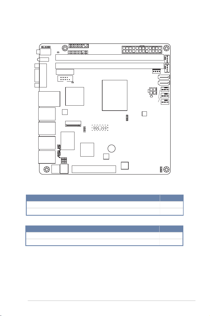
2.2.3 Motherboard layout
P9A-I/C2750/SAS/4L, P9A-I/C2550/SAS/4L
LAN34_LED1
PWR_SW1
LED1
VGA1
DM_LAN1
_USB2_1
LAN1
LAN2
LAN3
LAN4
SB_PWR1
64Mb
BIOS
BATTERY
M.2(SOCKET3)
Marvell
88E1543
Quad PHY
BMC
FW
P9A-I
COM1
BMC_LED1
AST2300
Realtek
RTL8211D
VGA_SW1
BMC_SW1
PHY_SW1
AUX_PANEL1
EATXPWR1
DDR3_DIMM_B1 (64bit, 240-pin module)
DDR3_DIMM_A1 (64bit, 240-pin module)
®
Intel
C-series FCBGA
processor
BUZZER
ICS
VR544200L
MSATA_SW1
Super
I/O
PANEL1
PCIE1
Atom
CLRTC1
ICS
3816565F
SATAPWR1
SATA6G_1
SATA6G_2
CON1
FRNT_FAN2
FRNT_FAN1
CPU_FAN1
RT8166B
Marvell
88SE9485
Marvell
88SE9485
TR1
MiniSAS4MiniSAS3MiniSAS2MiniSAS1
FRNT_FAN4FRNT_FAN3
ASUS P9A-I Series
2-5
Page 22
P9A-I/C2550/4L
LAN34_LED1
SB_PWR1
PWR_SW1
LED1
VGA1
DM_LAN1
_USB2_1
LAN1
LAN2
LAN3
LAN4
64Mb
BIOS
BATTERY
P9A-I/C2550/4L
COM1
BMC_LED1
AST2300
Realtek
RTL8211D
M.2(SOCKET3)
Marvell
88E1543
Quad PHY
VGA_SW1
BMC_SW1
PHY_SW1
BMC
FW
AUX_PANEL1
EATXPWR1
DDR3_DIMM_B1 (64bit, 240-pin module)
DDR3_DIMM_A1 (64bit, 240-pin module)
®
Intel
C-series FCBGA
processor
BUZZER
ICS
VR544200L
MSATA_SW1
Super
I/O
PANEL1
PCIE1
Atom
CLRTC1
ICS
3816565F
SATAPWR1
SATA6G_1
SATA6G_2
FRNT_FAN2
FRNT_FAN1
RT8166B
FRNT_FAN4FRNT_FAN3
CON1
CPU_FAN1
TR1
2.2.4 Layout contents
Slots/Sockets Page
1. DDR3 sockets 2-8
2. PCI Express x8 2-11
Onboard LEDs Page
1. Standby Power LED (SB_PWR1) 2-12
2. Baseboard Management Controller LED (BMC_LED1) 2-12
2-6
Chapter 2: Hardware information
Page 23

Jumpers Page
1. Clear RTC RAM (3-pin CLRTC1)
2. SATA M.2 and SATA II selection (3-pin MSATA_SW1)
3. VGA controller setting (3-pin VGA_SW1) 2-14
4. Baseboard Management Controller setting (3-pin BMC_SW1) 2-14
5. Marvell 88E1543 Quad PHY LAN controller setting (3-pin PHY_
SW1)
Rear panel connectors Page
1. Power button 2-15
2. Location LED 2-15
3. Message LED 2-15
4. HDD Error LED 2-15
5. Video Graphics Adapter port 2-15
6. USB 2.0 ports 1 and 2 2-15
7. RJ-45 ports (4 x GbE LAN, 1 x Management LAN) 2-15
2-13
2-13
2-14
Internal connectors Page
1. Serial ATA 6.0 Gb/s connectors
(7-pin SATA 6G_1 connector [Light Blue])
(7-pin SATA 6G_2 connector [Gray], for SATA 6.0 Gb/s or M.2
connector)
2. Mini-SAS connectors
3. CPU and front fan connectors
(4-pin CPU_FAN1, 4-pin FRNT_FAN1~4)
4. M.2 Socket 3
5. ATX power connectors (24-pin EATXPWR1, 4-pin CON1) 2-18
6. Serial port connector (10-1 pin COM1)
7. System panel connector (20-1 pin PANEL1)
8. LAN34_LED connector (5-1 pin LAN34_LED1)
9. SATA power connector (4-pin SATAPWR1)
10. Thermal sensor cable connector (3-pin TR1)
11. Auxiliary panel connector (20-2 pin AUX_PANEL1) 2-20
ASUS P9A-I Series
2-16
2-21
2-17
2-16
2-17
2-19
2-22
2-18
2-21
2-7
Page 24
2.3 Central Processing Unit (CPU)
The motherboard comes with an integrated Intel® Atom® C-Series FCBGA processor.
P9A-I
Integrated Intel
C-series FCBGA processor
®
Atom
P9A-I CPU
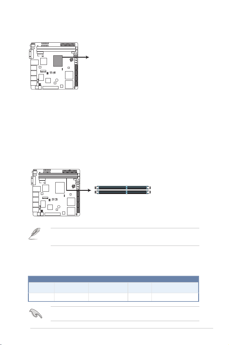
2.4 System memory
2.4.1 Overview
The motherboard comes with two Double Data Rate 3 (DDR3) Dual Inline Memory Modules
(DIMM) sockets.
A DDR3 module has the same physical dimensions as a DDR2 DIMM but is notched
differently to prevent installation on a DDR2 DIMM socket. DDR3 modules are developed for
better performance with less power consumption.
The gure illustrates the location of the DDR3 DIMM sockets:
P9A-I
DIMM_B1
DIMM_A1
P9A-I 240-pin DDR3 DIMM sockets
• When using only one memory module, install it into slot DIMM_A1.
• Always install identical DIMMs into both the slots.
2.4.2 Memory Configurations
You may install 2 GB, 4 GB, 8 GB, and 16 GB Unbuffered with ECC/Non-ECC DDR3 DIMMs
into the DIMM sockets using the memory congurations in this section.
DIMM Slot Per
Channel
2-8
DIMM Populated
per Channel
1 1 Unbuffered DDR3 1333/1600 Single Rank, Dual Rank
Always install DIMMs with the same CAS latency. For optimum compatibility, it is
recommended that you obtain memory modules from the same vendor.
UDIMM
DIMM Type Speed Rank per DIMM
Chapter 2: Hardware information
Page 25
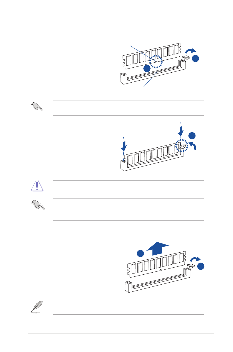
2.4.3 Installing a DIMM on a single clip DIMM socket
1. Unlock a DIMM socket by pressing the
retaining clip outward.
2. Align a DIMM on the socket such that
the notch on the DIMM matches the
DIMM slot key on the socket.
A DIMM is keyed with a notch so that it ts in only one direction. DO NOT force a DIMM into
a socket in the wrong direction to avoid damaging the DIMM.
3. Hold the DIMM by both of its ends
then insert the DIMM vertically into the
socket. Apply force to both ends of the
DIMM simultaneously until the retaining
clip snaps back into place and the
DIMM cannot be pushed in any further
to ensure proper sitting of the DIMM.
Always insert the DIMM into the socket vertically to prevent DIMM notch damage.
• To install two or more DIMMs, refer to the user guide bundled in the motherboard
package.
• Refer to the user guide for qualied vendor lists of the memory modules.
DIMM notch
DIMM slot key
1
2
Unlocked retaining clip
3
Locked Retaining Clip
Removing a DIMM from a single clip DIMM socket
1. Press the retaining clip outward to
unlock the DIMM.
2
2. Remove the DIMM from the socket.
Support the DIMM lightly with your ngers when pressing the retaining clips. The DIMM
might get damaged when it ips out with extra force.
ASUS P9A-I Series
1
2-9
Page 26

2.5 Expansion slots
In the future, you may need to install expansion cards. The following subsections describe the
slots and the expansion cards that they support.
Ensure to unplug the power cord before adding or removing expansion cards. Failure to do
so may cause you physical injury and damage motherboard components.
2.5.1 Installing an expansion card
To install an expansion card:
1. Before installing the expansion card, read the documentation that came with it and
make the necessary hardware settings for the card.
2. Remove the system unit cover (if your motherboard is already installed in a chassis).
3. Remove the bracket opposite the slot that you intend to use. Keep the screw for later
use.
4. Align the card connector with the slot and press rmly until the card is completely
seated on the slot.
5. Secure the card to the chassis with the screw you removed earlier.
6. Replace the system cover.
2.5.2 Configuring an expansion card
After installing the expansion card, congure it by adjusting the software settings.
1. Turn on the system and change the necessary BIOS settings, if any. See Chapter 4 for
information on BIOS setup.
2. Assign an IRQ to the card. Refer to the tables on the next page.
3. Install the software drivers for the expansion card.
When using PCI cards on shared slots, ensure that the drivers support “Share IRQ” or that
the cards do not need IRQ assignments. Otherwise, conicts will arise between the two PCI
groups, making the system unstable and the card inoperable.
2-10
Chapter 2: Hardware information
Page 27
2.5.3 Interrupt assignments
Standard Interrupt assignments
IRQ Priority Standard function
0 1 System Timer
1 2 Keyboard Controller
2 - Programmable Interrupt
3* 12 Communications Port (COM1)
4* 13 --
5 14 Floppy Disk Controller
6* 15 --
7 3 System CMOS/Real Time Clock
8* 4 ACPI Mode when used
9* 5 IRQ Holder for PCI Steering
10* 6 IRQ Holder for PCI Steering
11 8 Numeric Data Processor
12* 9 Primary IDE Channel
13* 10 Secondary IDE Channel
* These IRQs are usually available for ISA or PCI devices.
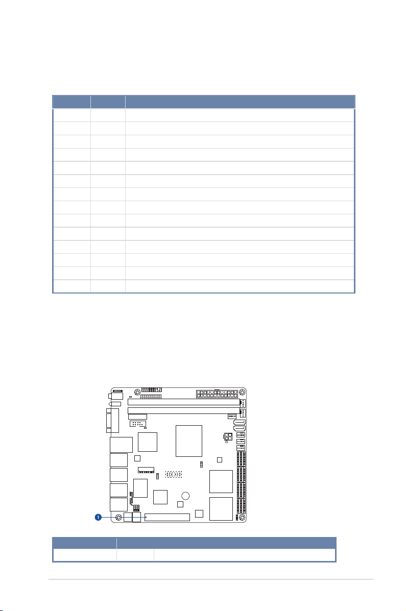
2.5.4 PCI Express x8 slot (x4 Gen2 link)
The onboard PCIE x8 slot provides one x4 Gen2 link to CPU1. This slot supports various
server class high performance add-on cards such as SCSI RAID card, ber-channel card,
and others.
P9A-I
No.(Slot location) Short Description
1
ASUS P9A-I Series
PCIE1
1 x PCI-E x8 (x4 Gen2 link)
2-11
Page 28
2.6 Onboard LEDs
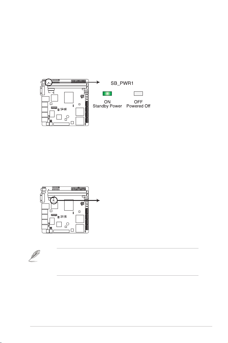
1. Standby Power LED (SB_PWR1)
The motherboard comes with a standby power LED. The green LED lights up to
indicate that the system is ON, in sleep mode, or in soft-off mode. This is a reminder
that you should shut down the system and unplug the power cable before removing or
plugging in any motherboard component. The illustration below shows the location of
the onboard LED.
P9A-I
P9A-I Standby power LED
2. Baseboard Management Controller LED (BMC_LED1)
The green heartbeat LED blinks per second to indicate that the ASMB7 is working
normally. The BMC LED works with the ASUS ASMB7 management device and
indicates its initiation status. When the PSU is plugged and the system is OFF, ASUS
ASMB7 management device starts system initiation for about one (1) minute. The BMC
LED blinks after system initiation nishes.
P9A-I BMC LED
2-12
P9A-I
BMC_LED1
• The heartbeat LED functions only when you install the ASUS ASMB7 Management
card.
• Everytime after the AC power is replugged, you have to wait for about 60 seconds
for the system to power up.
Chapter 2: Hardware information
Page 29
2.7 Jumpers
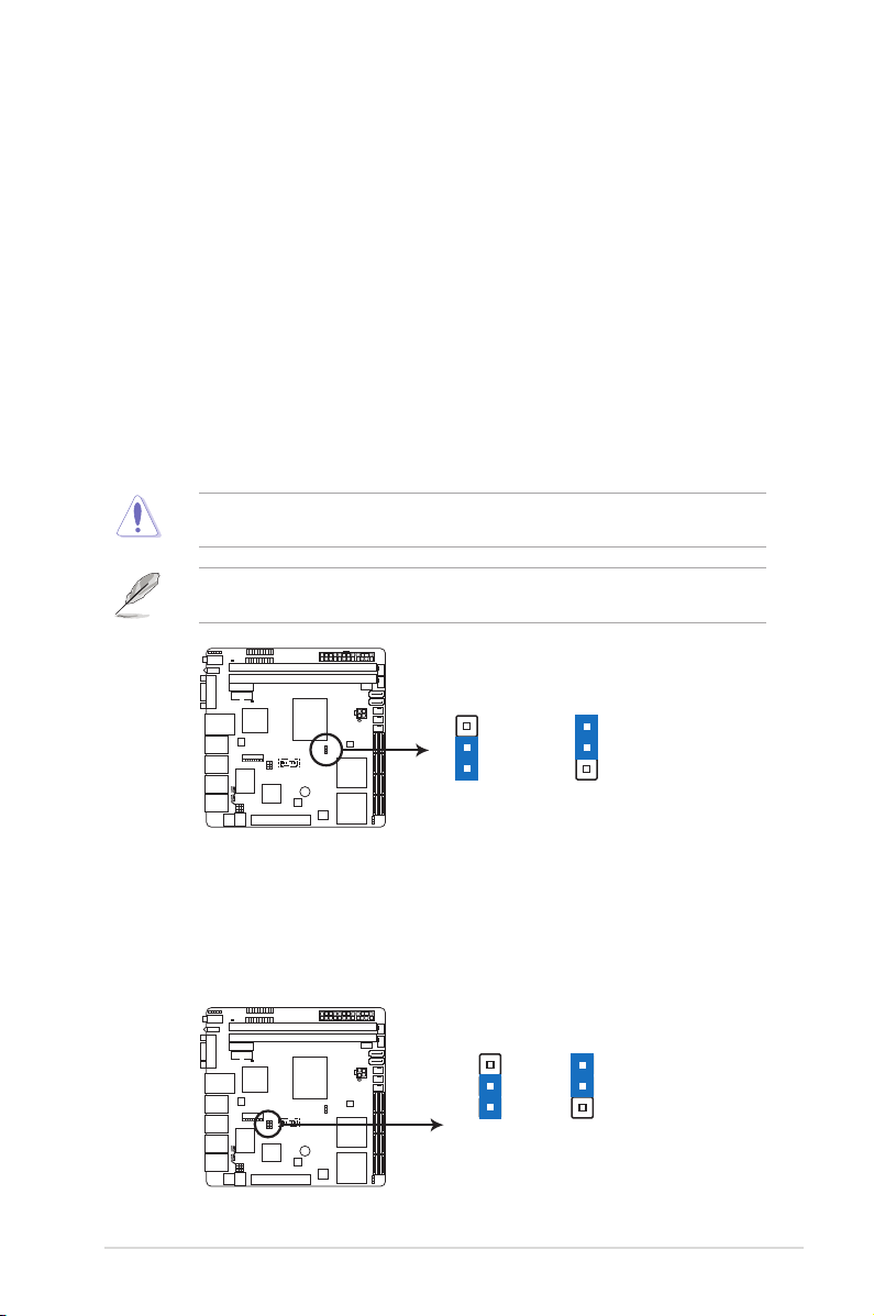
1. Clear RTC RAM (3-pin CLRTC1)
This jumper allows you to clear the Real Time Clock (RTC) RAM in CMOS. You can
clear the CMOS memory of date, time, and system setup parameters by erasing
the CMOS RTC RAM data. The onboard button cell battery powers the RAM data in
CMOS, which include system setup information such as system passwords.
To erase the RTC RAM:
1. Turn OFF the computer and unplug the power cord.
2. Move the jumper cap from pins 1–2 (default) to pins 2–3. Keep the cap on pins
2–3 for about 5–10 seconds, then move the cap back to pins 1–2.
3. Plug the power cord and turn ON the computer.
4. Hold down the <Del> key during the boot process and enter BIOS setup to reenter data.
Except when clearing the RTC RAM, never remove the cap on CLRTC jumper default
position. Removing the cap will cause system boot failure!
If the steps above do not help, remove the onboard battery and move the jumper again to
clear the CMOS RTC RAM data. After the CMOS clearance, reinstall the battery.
P9A-I
(Default)
1 2
Normal
CLRTC
2 3
Clear RTC
P9A-I Clear RTC RAM
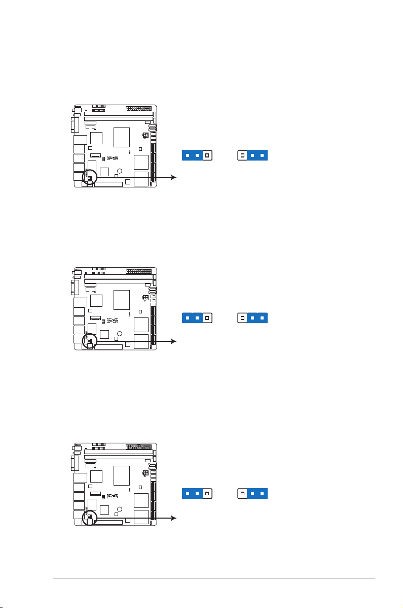
2. SATA M.2 and SATA III selection (3-pin MSATA_SW1)
Set to pins 1–2 to allow the system to automatically enable the SATA M.2 or SATA III
controllers when SATA M.2 or SATA III devices are detected. Set to pins 2–3 to enable
the SATA M.2 controller with SATA III interface disabled.
P9A-I
MSATA_SW1
Auto
(Default)
32
21
m2Sata
P9A-I SATA M.2 and SATA III selection
ASUS P9A-I Series
2-13
Page 30
3. VGA controller setting (3-pin VGA_SW1)
This jumper allows you to enable or disable the onboard VGA controller. Set to pins 1–
2 to activate the VGA feature.
P9A-I
VGA_SW1
1 2
2 3
Enable
(Default)
Disable
P9A-I VGA setting
4. Baseboard Management Controller setting (3-pin BMC_SW1)
This jumper allows you to enable or disable the ASMB7 remote server management
feature.
P9A-I
BMC_SW1
1 2
Enable
(Default)
2 3
Disable
P9A-I BMC setting
5. Marvell 88E1543 Quad PHY LAN controller setting (3-pin PHY_SW1)
This jumper allows you to enable or disable the onboard Marvell 88E1543 Quad PHY
LAN controller. Set to pins 1–2 to enable the onboard Marvell 88E1543 Quad PHY LAN
controller.
P9A-I
PHY_SW1
1 2
2 3
P9A-I LAN controller setting
2-14
Enable
(Default)
Disable
Chapter 2: Hardware information
Page 31

2.8 Connectors
2.8.1 Rear panel connectors
1
78 6
1. Power button.
2. RJ-45 port for BMC.
through a network hub for BMC management function. Refer to the table below for the
LAN port LED indications.
3. RJ-45 ports for LAN1-4.
Network (LAN) through a network hub. LAN1 can be congured as shared BMC LAN.
Refer to the table below for the LAN port LED indications.
4. USB 2.0 ports 1 and 2.
for connecting USB 2.0 devices.
5. Video Graphics Adapter (VGA) port.
VGA-compatible devices.
6. Message LED.
abnormal event occurance.
7. HDD Error LED.
8. Location LED.
Button on the front panel is pressed. This LED helps you visually locate the server
among other servers especially when you are located at the back of the server rack.
Press this button to turn the system on/off.
This port allows Gigabit connection to a Local Area Network (LAN)
These ports allows Gigabit connection to a Local Area
These two 4-pin Universal Serial Bus (USB) ports are available
The message LED is controlled by Hardware monitor to indicate an
The HDD Error LED lights up or ashes when HDD errors are found.
The Location LED is an onboard LED that ligths up when the Location
2
4
This 15-pin port is for a VGA monitor or other
35
LAN port LED indications
Activity/Link LED Speed LED
Status Description Status Description
Off No link Off 10 Mbps connection
Green Linked Orange 100 Mbps connection
Green
(Blinking)
Green
(Blinking then
steady)
ASUS P9A-I Series
Data activity Green 1 Gbps connection
Ready to wake
up from S5
mode
_ _
ACT/LINK
LED
LAN port
SPEED
LED
2-15
Page 32

2.8.2 Internal connectors
1. Serial ATA 6.0 Gb/s connectors
(7-pin SATA 6G_1 connector [Light Blue])
(7-pin SATA 6G_2 connector [Gray], for SATA 6Gb/s or M.2 connector)
These connectors are for the Serial ATA signal cables for Serial ATA hard disk drives
that allows up to 6Gb/s of data transfer rate.
SATA6G_1
GND
GND
GND
RSATA_TXP1
RSATA_TXN1
RSATA_RXP1
P9A-I
P9A-I SATA 6.0Gb/s connectors
• The actual data transfer rate depends on the speed of Serial ATA hard disks installed.
• The gray SATA port 2 shares bandwidth with M.2 Socket 3. Refer to section
Jumpers
of this user guide for more details.
RSATA_RXN1
SATA6G_2
GND
GND
RSATA_TXP2
RSATA_TXN2
RSATA_RXN2
GND
RSATA_RXP2
2.7
2. M.2 Socket 3
This socket allows you to install an M.2 (NGFF) SSD module.
P9A-I
M.2(SOCKET3)
P9A-I M.2(SOCKET3)
• This socket supports M Key and type 2242 storage devices.
• The M.2 Socket 3 shares bandwidth with SATA port 2. Refer to section 2.7 Jumpers
of this user guide for more details.
The M.2 (NGFF) SSD module is purchased separately.
2-16
Chapter 2: Hardware information
Page 33

3. CPU and front fan connectors (4-pin CPU_FAN1, FRNT_FAN1~4)
The fan connectors support cooling fans. Connect the fan cables to the fan connectors
on the motherboard, ensuring that the black wire of each cable matches the ground pin
of the connector.
• DO NOT forget to connect the fan cables to the fan connectors. Insufcient air ow
inside the system may damage the motherboard components.
• These are not jumpers! DO NOT place jumper caps on the fan connectors!
• All fans feature the ASUS Smart Fan technology.
A
C
FRNT_FAN2FRNT_FAN4
GND
A
B
C
D
E
P9A-I
FRNT_FAN3
VCC
SENSE
PWM
B
FRNT_FAN1
GND
VCC
SENSE
PWM
VCC
GND
PWM
SENSE
D E
CPU_FAN1
VCC
GND
PWM
SENSE
PWM
VCC
SENSE
P9A-I Fan connectors
4. Serial port connector (10-1 pin COM1)
This connector is for a serial (COM) port. Connect the serial port module cable to this
connector, then install the module to a slot opening at the back of the system chassis.
COM1
RXD
DTR
DSR
P9A-I
CTS
GND
P9A-I Serial port connector
ASUS P9A-I Series
PIN 1
DCD
TXD
GND
RTS
RI
2-17
Page 34

5. ATX power connectors (24-pin EATXPWR1, 4-pin CON1)
These connectors are for the ATX power supply plugs. The power supply plugs are
designed to t these connectors in only one orientation. Find the proper orientation and
push down rmly until the connectors completely t.
• DO NOT forget to connect the 24-pin and the 4-pin power plugs; otherwise, the system
will not boot up.
• Use of a power supply unit (PSU) with a higher power output is recommended when
conguring a system with more power-consuming devices. The system may become
unstable or may not boot up if the power is inadequate.
• This motherboard supports ATX2.0 PSU or later version.
• Ensure that your PSU can provide at least the minimum power required by your
system.
A
EATXPWR1
+12V DC
+12V DC
CON1
A
P9A-I
B
B
PIN 1
GND
GND
P9A-I ATX power connectors
6. SATA power connector (4-pin SATAPWR1)
This connector is for the SATA power cable. The power cable plug is designed to t
this connector in only one orientation. Find the proper orientation and push down rmly
until the connector completely t.
P9A-I
SATAPWR1
+5V
+5V
GND
GND
P9A-I SATA power connector
2-18
Chapter 2: Hardware information
Page 35

7. System panel connector (20-1 pin PANEL1)
This connector supports several chassis-mounted functions.
P9A-I
P9A-I System panel connector
1. Reset button (2-pin RESET)
This 2-pin connector is for the chassis-mounted reset button for system reboot
without turning off the system power.
2. Power button/soft-off button (2-pin PWRSW)
This connector is for the system power button. Pressing the power button turns
the system on or puts the system in sleep or soft-off mode depending on the
BIOS settings. Pressing the power switch for more than four seconds while the
system is ON turns the system OFF.
3. Hard disk drive activity LED (2-pin +HDLED)
This 2-pin connector is for the HDD Activity LED. Connect the HDD Activity LED
cable to this connector. The HDD Activity LED lights up or ashes when data is
read from or written to the HDD.
4. System warning speaker (4-pin SPEAKER)
This 4-pin connector is for the chassis-mounted system warning speaker. The
speaker allows you to hear system beeps and warnings.
5. Message LED (2-pin MLED)
This 2-pin connector is for the message LED cable that connects to the front
message LED. The message LED is controlled by Hardware monitor to indicate
an abnormal event occurance.
6. System power LED (3-pin PLED)
This 3-pin connector is for the system power LED. Connect the chassis power
LED cable to this connector. The system power LED lights up when you turn on
the system power, and blinks when the system is in sleep mode.
ASUS P9A-I Series
2-19
Page 36

8. Auxiliary panel connector (20-2 pin AUX_PANEL1)
This connector is for additional front panel features including front panel SMB, locator
LED and switch, chassis intrusion, and LAN LEDs.
P9A-I
P9A-I Auxiliary panel connector
1. Front panel SMB (6-1 pin FPSMB)
These LEDs connect the front panel SMBus cable.
2. LAN activity LED (2-pin LAN1LINK and 2-pin LAN2LINK)
These LEDs are for Gigabit LAN activity LEDs on the front panel.
3. Chassis intrusion (4-1 pin AUX_CHASSIS)
These LEDs are for the intrusion detection feature for chassis with intrusion
sensor or microswitch. When you remove any chassis component, the sensor
triggers and sends a high-level signal to these LEDs to record a chassis intrusion
event. The default setting is short CASEOPEN and GND pin by jumper cap to
disable the function.
4. Locator LED (2-pin AUX_LOCLED1 and 2-pin AUX_LOCLED2)
These LEDs are for the Locator LED1 and LED2 on the front panel. Connect the
Locator LED cables to these 2-pin connector. The LEDs will light up when the
Locator button is pressed.
5. Locator Button/Switch (2-pin AUX_BMCLOCBNT)
These LEDs are for the locator button on the front panel. This button queries the
state of the system locator.
2-20
Chapter 2: Hardware information
Page 37

9. Mini-SAS connectors (MiniSAS1~4)
This motherboard comes with four mini Serial Attached SCSI (SAS) connectors, the
storage technology that supports both Serial Attached SCSI and Serial ATA. Each
connector supports up to four deives.
MiniSAS4
MiniSAS3
MiniSAS2
P9A-I
MiniSAS1
P9A-I Mini-SAS connector
10. Thermal sensor cable connector (3-pin TR1)
These connectors are for temperature monitoring. Connect the thermal sensor cables
to these connectors and place the other ends to the devices, which you want to monitor
temperature.
P9A-I
TR1
TR1
GND
TR1
P9A-I Thermal sensor cable connector
ASUS P9A-I Series
2-21
Page 38

11. LAN34_LED connector (5-1 pin LAN34_LED1)
These LEDs are for Gigabit LAN activity LEDs on the front panel. Connect the LAN
LED cable to the backplane for LAN activity indication.
LAN34_LED1
PIN 1
P9A-I
AUX_LAN3LINK#
AUX_LAN3ACT#
AUX_LAN4ACT#
AUX_LAN4LINK#
3 4
P9A-I LAN3 & LAN4 LED
2-22
Chapter 2: Hardware information
Page 39

Chapter 3: Powering Up
Page 40

Chapter summary
3
This chapter describes the power up sequence, and ways of shutting down the system.This
chapter contains the following sections:
3.1 Starting up for the first time ...................................................................... 3-3
3.2 Powering off the computer ........................................................................3-4
ASUS P9A-I Series
Page 41

3.1 Starting up for the first time
1. After making all the connections, replace the system case cover.
2. Be sure that all switches are off.
3. Connect the power cord to the power connector at the back of the system chassis.
4. Connect the power cord to a power outlet that is equipped with a surge protector.
5. Turn on the devices in the following order:
a. Monitor
b. External storage devices (starting with the last device on the chain)
c. System power
6. After applying power, the system power LED on the system front panel case lights up.
For systems with ATX power supplies, the system LED lights up when you press the
ATX power button. If your monitor complies with “green” standards or if it has a “power
standby” feature, the monitor LED may light up or switch between orange and green
after the system LED turns on.
The system then runs the power-on self-test or POST. While the tests are running, the
BIOS beeps or additional messages appear on the screen. If you do not see anything
within 30 seconds from the time you turned on the power, the system may have failed
a power-on test. Check the jumper settings and connections or call your retailer for
assistance.
7. At power on, hold down the <Del> key to enter the BIOS Setup. Follow the instructions
in Chapter 4.
ASUS P9A-I Series
3-3
Page 42

3.2 Powering off the computer
3.2.1 Using the OS shut down function
Using Windows® Server 2008 R2:
1. Click the
2. From the
3. Ensure that the
4. If necessary, key in comments.
5. Click OK.
Using Windows® Server 2012:
1. Press <Ctrl>+<Alt>+<Del>.
2. Click on the Power icon on the lower right side of the screen.
3. Select
4. In the Shutdown Event Tracker, select the
5. Click
Start
Shut Down
want to shut down the computer.
lists. Otherwise, select the option that best describes why you want to shut down the
computer.
button, move the cursor to the triangle on the right of Log off, then click
.
Shutdown Event Tracker
Shut down
Continue
Planned
.
check box is checked.
.
, select the option that best describes why you
Other (Planned)
option in the selection
3.2.2 Using the dual function power switch
While the system is ON, press the power switch for less than four seconds to put the system
to sleep mode or to soft-off mode, depending on the BIOS setting.
Pressing the power switch for more than four seconds lets the system enter the soft-off mode
regardless of the BIOS setting.
3-4
Chapter 3: Powering up
Page 43

Chapter 4: BIOS setup
Page 44

Chapter summary
4
This chapter tells how to change the system settings through the BIOS Setup menus.
Detailed descriptions of the BIOS parameters are also provided.
This chapter contains the following sections:
4.1 Managing and updating your BIOS .......................................................... 4-3
4.2 BIOS setup program .................................................................................. 4-7
4.3 Main menu ................................................................................................4-10
4.4 Advanced menu .......................................................................................4-11
4.5 IntelRCSetup menu .................................................................................. 4-28
4.6 Server Mgmt menu ................................................................................... 4-50
4.7 Event Logs menu ..................................................................................... 4-55
4.8 Security ..................................................................................................... 4-57
4.9 Boot menu ................................................................................................4-60
4.10 Monitor menu ........................................................................................... 4-61
4.11 Tool menu ................................................................................................. 4-62
4.12 Exit menu .................................................................................................. 4-62
ASUS P9A-I Series
Page 45

4.1 Managing and updating your BIOS
The following utilities allow you to manage and update the motherboard Basic Input/Output
System (BIOS) setup:
ASUS CrashFree BIOS 3
1.
To recover the BIOS using a bootable USB ash disk drive when the BIOS le fails or
gets corrupted.
ASUS EzFlash
2.
Updates the BIOS using a USB ash disk.
BUPDATER
3.
Updates the BIOS in DOS mode using a bootable USB ash disk drive.
Refer to the corresponding sections for details on these utilities.
Save a copy of the original motherboard BIOS le to a bootable USB ash disk drive in
case you need to restore the BIOS in the future. Copy the original motherboard BIOS using
the BUPDATER utility.
4.1.1 ASUS CrashFree BIOS 3 utility
The ASUS CrashFree BIOS 3 is an auto recovery tool that allows you to restore the BIOS le
when it fails or gets corrupted during the updating process. You can update a corrupted BIOS
le using a USB ash drive that contains the updated BIOS le.
Prepare a USB ash drive containing the updated motherboard BIOS before using this
utility.
Recovering the BIOS from a USB flash drive
To recover the BIOS from a USB ash drive:
1. Insert the USB ash drive with the original or updated BIOS le to one USB port on the
system.
2. The utility will automatically recover the BIOS. It resets the system when the BIOS
recovery nished.
DO NOT shut down or reset the system while recovering the BIOS! Doing so would cause
system boot failure!
The recovered BIOS may not be the latest BIOS version for this motherboard. Visit the
ASUS website at www.asus.com to download the latest BIOS le.
ASUS P9A-I Series
4-3
Page 46

4.1.2 ASUS EzFlash Utility
The ASUS EzFlash Utility feature allows you to update the BIOS using a USB ash disk
without having to use a DOS-based utility.
Download the latest BIOS from the ASUS website at www.asus.com before using this
utility.
The succeeding BIOS screens are for reference only. The actual BIOS screen displays
may not be the same as shown.
To update the BIOS using EzFlash Utility:
1. Insert the USB ash disk that contains the latest BIOS le to the USB port.
2. Enter the BIOS setup program. Go to the Tool menu to select ASUS EzFlash Utility
and press <Enter> to enable it.
ASUS Tek. EzFlash Utility
Current Platform
Platform : P9A-I
Version : 0201
Build Date :04/10/2014
FS0
System Volume Information <DIR>
P9A-I Bios
P9A-I Bios <DIR>
Windows <DIR>
New Platform
Platform : P9A-I
Version : 0202
Build Date :04/15/2014
<DIR>
[Up/Down/Left/Right]:Switch [Enter]:Choose [q]:Exit
3. Press <Tab> to switch to the Drive eld.
4. Press the Up/Down arrow keys to nd the USB ash disk that contains the latest BIOS
then press <Enter>.
5. Press <Tab> to switch to the Folder Info eld.
6. Press the Up/Down arrow keys to nd the BIOS le then press <Enter>.
7. Reboot the system when the update process is done.
4-4
Chapter 4: BIOS setup
Page 47

• This function can support devices such as a USB ash disk with FAT 32/16 format and
single partition only.
• DO NOT shut down or reset the system while updating the BIOS to prevent system
boot failure!
Ensure to load the BIOS default settings to ensure system compatibility and stability. Press
<F5> and select Yes to load the BIOS default settings.
4.1.3 BUPDATER utility
The succeeding BIOS screens are for reference only. The actual BIOS screen displays may
not be the same as shown.
The BUPDATER utility allows you to update the BIOS le in DOS environment using a
bootable USB ash disk drive with the updated BIOS le.
Updating the BIOS file
To update the BIOS le using the BUPDATER utility:
1. Visit the ASUS website at www.asus.com and download the latest BIOS le for the
motherboard. Save the BIOS le to a bootable USB ash disk drive.
2. Download the BUPDATER utility (BUPDATER.exe) from the ASUS support website at
support.asus.com to the bootable USB ash disk drive you created earlier.
3. Boot the system in DOS mode, then at the prompt, type:
BUPDATER /i[lename].CAP
where [lename] is the latest or the original BIOS le on the bootable USB ash disk
drive, then press <Enter>.
A:\>BUPDATER /i[le name]CAP
ASUS P9A-I Series
4-5
Page 48

The utility veries the le, then starts updating the BIOS le.
FLASH TYPE: MXIC 25L1605A
PATH:
Writing BIOS:
ASUSTek BIOS Update for DOS V1.06 (09/08/04)
Current ROM Update ROM
BOARD: P9A-I
VER: 0201
DATE: 04/10/2014
WARNING! Do not turn off power during ash BIOS
Note
BOARD: P9A-I
VER: 0202
DATE: 04/15/2014
DO NOT shut down or reset the system while updating the BIOS to prevent system boot
failure!
The utility returns to the DOS prompt after the BIOS update process is completed.
4. Reboot the system from the hard disk drive.
The BIOS update is nished! Please restart your system.
C:\>
4-6
Chapter 4: BIOS setup
Page 49

4.2 BIOS setup program
This motherboard supports a programmable rmware chip that you can update using the
provided utility described in section
Use the BIOS Setup program when you are installing a motherboard, reconguring your
system, or prompted to “Run Setup.” This section explains how to congure your system
using this utility.
Even if you are not prompted to use the Setup program, you can change the conguration of
your computer in the future. For example, you can enable the security password feature or
change the power management settings. This requires you to recongure your system using
the BIOS Setup program so that the computer can recognize these changes and record them
in the CMOS RAM of the rmware chip.
The rmware chip on the motherboard stores the Setup utility. When you start up the
computer, the system provides you with the opportunity to run this program. Press <Del>
during the Power-On Self-Test (POST) to enter the Setup utility; otherwise, POST continues
with its test routines.
If you wish to enter Setup after POST, restart the system by pressing <Ctrl>+<Alt>+<Del>,
or by pressing the reset button on the system chassis. You can also restart by turning the
system off then back on. Do this last option only if the rst two failed.
The Setup program is designed to make it as easy to use as possible. Being a menu-driven
program, it lets you scroll through the various sub-menus and make your selections from the
available options using the navigation keys.
• The default BIOS settings for this motherboard apply for most conditions to ensure
optimum performance. If the system becomes unstable after changing any BIOS
settings, load the default settings to ensure system compatibility and stability. Press
<F5> and select
• The BIOS setup screens shown in this section are for reference purposes only, and
may not exactly match what you see on your screen.
• Visit the ASUS website (www.asus.com) to download the latest BIOS le for this
motherboard.
4.1 Managing and updating your BIOS
Yes
to load the BIOS default settings.
.
ASUS P9A-I Series
4-7
Page 50

4.2.1 BIOS menu screen
Menu bar Configuration fieldsMenu items
Aptio Setup Utility - Copyright (C) 2013 American Megatrends, Inc.
Main Advanced IntelRCSetup Server Mgmt Event Logs Security Boot Monitor Tool Exit
BIOS Information
BIOS Vendor American Megatrends
Core Version 5.009
Compliancy UEFI 2.3.1; PI 1.2
BIOS Version 0202 x64
Build Date 04/15/2014
System Language [English]
System Date [Saturday 01/01/2000]
System Time [00:38:01]
Access Level Administrator
Version 2.16.1243. Copyright (C) 2013 American Megatrends, Inc.
Choose the system default
language
General help
Select Screen
→←:
Select Item
↑↓:
Enter: Select
+/-: Change Opt.
F1: General Help
F2: Previous Values
F5: Optimized Defaults
F10: Save & Exit
ESC: Exit
Navigation keys
4.2.2 Menu bar
The menu bar on top of the screen has the following main items:
Main
For changing the basic system conguration
Advanced
IntelRCSetup
Server Mgmt
Event Logs
Security
Boot
Monitor
Tool
Exit
For changing the advanced system settings
For changing the processor and chipset settings
For changing the Server Management settings
For changing the event log settings
For changing the security settings
For changing the system boot conguration
For displaying the system temperature, power status, and changing
the fan settings
For conguring options for special functions
For selecting the exit options
To select an item on the menu bar, press the right or left arrow key on the keyboard until the
desired item is highlighted.
4-8
Chapter 4: BIOS setup
Page 51

4.2.3 Menu items
The highlighted item on the menu bar displays the specic items for that menu. For example,
selecting
Monitor, Security, Tool, and Exit) on the menu bar have their respective menu items.
Main
shows the Main menu items. The other items (Advanced, Event Logs, Boot,
4.2.4 Submenu items
A solid triangle before each item on any menu screen means that the item has a submenu.
To display the submenu, select the item and press <Enter>.
Aptio Setup Utility - Copyright (C) 2013 American Megatrends, Inc.
Main Advanced IntelRCSetup Server Mgmt Event Logs Security Boot Monitor Tool Exit
Enable CRID [Disabled]
ACPI Settings
NCT6779D Super IO Conguration
Enable Compatible Revision
ID
4.2.5 Navigation keys
At the bottom right corner of a menu screen are the navigation keys for the BIOS setup
program. Use the navigation keys to select items in the menu and change the settings.
4.2.6 General help
At the top right corner of the menu screen is a brief description of the selected item.
4.2.7 Configuration fields
These elds show the values for the menu items. If an item is user-congurable, you can
change the value of the eld opposite the item. You cannot select an item that is not usercongurable. A congurable eld is enclosed in brackets, and is highlighted when selected.
To change the value of a eld, select it and press <Enter> to display a list of options.
4.2.8 Pop-up window
Select a menu item and press <Enter> to display a pop-up window with the conguration
options for that item.
4.2.9 Scroll bar
A scroll bar appears on the right side of a menu screen when there are items that do not t
on the screen. Press the Up/Down arrow keys or <Page Up> /<Page Down> keys to display
the other items on the screen.
ASUS P9A-I Series
4-9
Page 52

4.3 Main menu
When you enter the BIOS Setup program, the Main menu screen appears. The Main menu
provides you an overview of the basic system information, and allows you to set the system
date, time, and language settings.
Aptio Setup Utility - Copyright (C) 2013 American Megatrends, Inc.
Main Advanced IntelRCSetup Server Mgmt Event Logs Security Boot Monitor Tool Exit
BIOS Information
BIOS Vendor American Megatrends
Core Version 5.009
Compliancy UEFI 2.3.1; PI 1.2
BIOS Version 0202 x64
Build Date 04/15/2014
System Language [English]
System Date [Saturday 01/01/2000]
System Time [00:38:01]
Choose the system default
language
Access Level Administrator
Version 2.16.1243. Copyright (C) 2013 American Megatrends, Inc.
Select Screen
→←:
Select Item
↑↓:
Enter: Select
+/-: Change Opt.
F1: General Help
F2: Previous Values
F5: Optimized Defaults
F10: Save & Exit
ESC: Exit
4.3.1 System Language [English]
Allows you to choose the BIOS language version from the options. Conguration options:
[English]
4.3.2 System Date
Allows you to set the system date to
Where:
Day = Day of the week
mm = month (numeric value)
dd = day (numeric value)
yyyy = year (numeric value)
[Day mm/dd/yyyy]
.
4.3.3 System Time
Allows you to set the system time to
Where:
hh = hour (numeric value)
mm = minutes (numeric value)
ss = seconds (numeric value)
[hh/mm/ss]
.
4-10
Chapter 4: BIOS setup
Page 53

4.4 Advanced menu
The Advanced menu items allow you to change the settings for the CPU and other system
devices.
Take caution when changing the settings of the Advanced menu items. Incorrect eld
values can cause the system to malfunction.
Aptio Setup Utility - Copyright (C) 2013 American Megatrends, Inc.
Main Advanced IntelRCSetup Server Mgmt Event Logs Security Boot Monitor Tool Exit
PCI Subsystem Settings
Enable CRID [Disabled]
ACPI Settings
Trusted Computing
ACPI Settings
WHEA Conguration
CPU Conguration
NCT6779D Super IO Conguration
PCH-IO Conguration
Serial Port Console Redirection
SATA Conguration
Systems Agent (SA) Conguration
Onboard LAN I354 Conguration
USB Conguration
APM
NCT6779D Super IO Conguration
Intel Server Platforms Services
PCI Subsystem Settings
Onboard LAN Conguration
Network Stack Conguration
MIO Card Conguration
Serial Port Console Redirection
CSM Conguration
APM
Trusted Computing
Network Stack
Intel RC Drivers Version Details
USB Conguration
iSCSI Conguration
Intel(R) Ethernet Connection I354-40:16:7E:7F:D8:07
Intel(R) Ethernet Connection I354-40:16:7E:7F:D8:08
Intel(R) Ethernet Connection I354-40:16:7E:7F:D8:09
Intel(R) Ethernet Connection I354-40:16:7E:7F:D8:0A
Driver Health
PCI, PCI-X and PCI Express
Enable Compatible Revision
Settings.
ID
4.4.1 Enable CRID [Disabled]
Allows you to enable or disable the compatible revision ID. Conguration options: [Enabled]
[Disabled]
ASUS P9A-I Series
4-11
Page 54

4.4.2 ACPI Settings
Advanced
ACPI Settings
Enable ACPI Auto Conguration [Disabled]
Enable Hibernation [Disabled]
ACPI Sleep State [Suspend Disabled]
Lock Legacy Resources [Disabled]
Enable ACPI Auto Configuration [Disabled]
Allows you to enable or disable BIOS ACPI Auto Conguration. Conguration options:
[Enabled] [Disabled]
Aptio Setup Utility - Copyright (C) 2013 American Megatrends, Inc.
Enables or Disables BIOS
ACPI Auto Conguration.
Enabled for Windows XP and
Linux (OS optimized for
Hyper-Threading Technology)
and Disabled for other OS
(OS not optimized for Hyper-
Threading Technology).
When Disabled only one thread
per enabled core is enabled.
→←: Select Screen
↑↓: Select Item
Enter: Select
+/-: Change Opt.
This following items appear only when you set
Enable ACPI Auto Configuration
to
[Disabled].
Enable Hibernation [Disabled]
Enables or disables system ability to Hibernate (0S/S4 sleep state). This option may be not
effective with some OS. Conguration options: [Enabled] [Disabled]
ACPI Sleep State [Suspend Disabled]
Allows you to set the ACPI Sleep State. Conguration options: [Suspend Disabled] [S3 only
(Suspend to RAM)]
Lock Legacy Resources [Disabled]
Allows you to enable or disable Lock Legacy Resources. Conguration options: [Enabled]
[Disabled]
4-12
Chapter 4: BIOS setup
Page 55

4.4.3 NCT6779D Super IO Configuration
Aptio Setup Utility - Copyright (C) 2013 American Megatrends, Inc.
Advanced
NCT6779D Super IO Conguration
Super IO Chip NCT6779D
Serial Port 1 Conguration
Parallel Port Conguration
Serial Port 1 Configuration
The sub-items in this menu allows you to set the parameters of the Serial Port 1 (COM1).
Serial Port [Enabled]
Allows you to enable or disable the serial port (COM 1/2). Conguration options:
[Enabled] [Disabled]
Change Settings [Auto]
This item only appears when you set the Serial Port to [Enabled]. This item allows you
to select the serial port base address. Conguration options:
[Auto]
[IO=3F8h; IRQ=4]
[IO=3F8h: IRQ=3, 4, 5, 6, 7, 9, 10, 11, 12]
[IO=2F8h; IRQ=3, 4, 5, 6, 7, 9, 10, 11, 12]
[IO=3E8h; IRQ=3, 4, 5, 6, 7, 9, 10, 11, 12]
[IO=2E8h; IRQ=3, 4, 5, 6, 7, 9, 10, 11, 12]
Parallel Port Configuration
The sub-items in this menu allow you to set the parallel port conguration.
Parallel Port [Enabled]
Allows you to enable or disable the parallel port (LPT/LPTE). Conguration
options: [Enabled] [Disabled]
Set Parameters of
Serial Port 1 (COMA)
The following items appear only when you set
Change Settings [Auto]
Allows you to select an optimal setting for Super I/O devices. Conguration
options: [Auto] [IO=378h; IRQ=5;] [IO=378h; IRQ=5,6,7,9,10,11,12;]
[IO=278h; IRQ=5,6,7,9,10,11,12;] [IO=3BCh; IRQ=5,6,7,9,10,11,12;]
Device Mode [STD Printe...]
Allows you to select the Printer Port mode. Conguration options: [STD
Printer Mode] [SPP Mode] [EPP-1.9 and SPP Mode] [EPP-1.7 and SPP
Mode] [ECP Mode] [ECP and EPP 1.9 Mode] [ECP and EPP 1.7 Mode]
ASUS P9A-I Series
Parallel Port Configuration
to [Enabled].
4-13
Page 56

4.4.4 Serial Port Console Redirection
Advanced
COM1
Console Redirection [Disabled]
Console Redirection Settings
COM2 (Disabled)
Console Redirection Port Is Disabled
Serial Port for Out-of-Band Management/
Windows Emergency Management Services (EMS)
Console Redirection [Disabled]
Console Redirection Settings
COM1 Console Redirection [Disabled]
Allows you to enable or disable the console redirection feature. Conguration options:
[Disabled] [Enabled]
Aptio Setup Utility - Copyright (C) 2013 American Megatrends, Inc.
Console Redirection
Enable or Disable.
Console Redirection Settings
The
set to [Enabled].
becomes congurable when
Console Redirection
is
COM1 Console Redirection Settings
The settings specify how the host computer and the remote computer (which the user is
using) will exchange data. Both computers should have the same or compatible settings.
Terminal Type [VT-UTF8]
Allows you to set the terminal type.
[VT100] ASCII char set.
[VT100+] Extends VT100 to support color, function keys, among others
[VT-UTF8] Uses UTF8 encoding to map Unicode chars onto 1 or more bytes
[ANSI] Extended ASCII char set
Bits per second [57600]
Selects serial port transmission speed. The speed must be matched on the other side.
Long or noisy lines may require lower speeds. Conguration options: [9600] [19200]
[38400] [57600] [115200]
Data Bits [8]
Allows you to set the data bits. Conguration options: [7] [8]
Parity [None]
Allows you to select the parity bit. A parity bit is sent with the data bits to detect
transmission errors. Conguration options: [None] [Even] [Odd] [Mark] [Space]
Stop Bits [1]
Stop bits indicate the end of a serial data packet. (A start bit indicates the beginning.)
The standard setting is 1 stop bit. Communication with slow devices may require more
than 1 stop bit. Conguration options: [1] [2]
4-14
Chapter 4: BIOS setup
Page 57

Flow Control [Hardware RTS/CTS]
Flow control can prevent data loss from buffer overow. When sending data, if the
receiving buffers are full, a “stop” signal can be sent to stop the data ow. Once the
buffers are empty, a “start” signal can be sent to re-start the ow. Hardware ow control
uses two wires to send start/stop signals. Conguration options: [None] [Hardware
RTS/CTS]
VT -UTF8 Combo Key Support [Enabled]
This allows you to enable the VT -UTF8 Combination Key Support for ANSI/VT100
terminals. Conguration options: [Disabled] [Enabled]
Recorder Mode [Disabled]
This allows you to enable or disable the Recorded mode to capture Terminal data.
Conguration options: [Disabled] [Enabled]
Legacy OS Redirection Resolution [80x24]
This allows you to set the number of rows and columns supported on the Legacy OS.
Conguration options: [80x24] [80x25]
Putty Keypad [VT100]
This allows you to select the FunctionKey and Keypad on Putty. Conguration options:
[VT100] [LINUX] [XTERMR6] [SCO] [ESCN] [VT400]
Redirection After BIOS POST [Always Enable]
This setting allows you to specify if Bootloader is selected than Legacy console
redirection. Conguration options: [Always Enable] [Bootloader]
Serial Port for Out-of-Band Management/Windows Emergency Management
Services (EMS) Settings
The following items only appears when you set the
Console Redirection
to [Enabled].
Out-of-Band Mgmt Port [COM1]
Allows remote management of a Windows Server OS through a serial port.
Conguration options: [COM1] [COM2(Disabled)]
Terminal Type [VT-UTF8]
Allows you to set the terminal type for out-of-band management. Conguration options:
[VT100] ASCII char set.
[VT100+] Extends VT100 to support color, function keys, et.
[VT-UTF8] Uses UTF8 encoding to map Unicode chars onto 1 or more bytes
[ANSI] Extended ASCII char set
Bits per second [115200]
Selects serial port transmission speed. The speed must be matched on the other side.
Long or noisy lines may require lower speeds. Conguration options: [9600] [19200]
[57600] [115200]
Flow Control [None]
Allows you to set the ow control to prevent data loss from buffer overow.
Conguration options: [None] [Hardware RTS/CTS] [Software Xon/Xoff]
ASUS P9A-I Series
4-15
Page 58

4.4.5 Onboard LAN I354 Configuration
This allows you to change the enable or disable the onboard LAN.
Advanced
Onboard LAN I354 Conguration
INTEL I354 LAN1 MAC: 40:16:7E:7F:D8:07
INTEL I354 LAN2 MAC: 40:16:7E:7F:D8:08
INTEL I354 LAN3 MAC: 40:16:7E:7F:D8:09
INTEL I354 LAN4 MAC: 40:16:7E:7F:D8:0A
INTEL Lan1 Enable [Enabled]
INTEL LAN ROM Type [PXE]
INTEL Lan2 Enable [Enabled]
INTEL LAN ROM Type [PXE]
INTEL Lan3 Enable [Enabled]
INTEL LAN ROM Type [PXE]
INTEL Lan4 Enable [Enabled]
INTEL LAN ROM Type [PXE]
Aptio Setup Utility - Copyright (C) 2013 American Megatrends, Inc.
Intel LAN
Enable/Disable
Intel Lan1/Lan2/Lan3/Lan4 Enable [Enabled]
Allows you to enable or disable the Intel LAN function in the system. Conguration Options:
[Enabled] [Disabled]
Intel Lan1/Lan2/Lan3/Lan4 ROM Type [PXE]
Allows you to launch the Intel LAN OpROM. Conguration options: [Disabled] [PXE] [iSCSI]
4-16
Chapter 4: BIOS setup
Page 59

4.4.6 APM
Allows you to congure the Advance Power Management (APM) settings.
Advanced
Restore AC Power Loss [Last State]
Power On By PS/2 Keyboard [Disabled]
Power On By PS/2 Mouse [Disabled]
Power On By PCIE [Disabled]
Power On By Ring [Disabled]
Power On By RTC [Disabled]
Aptio Setup Utility - Copyright (C) 2013 American Megatrends, Inc.
Specify what state
to go to when power
is re-applied after
a power failure (G3
state).
Restore AC Power Loss [Last State]
Allows you to set the state the system will go to after an AC power loss. Conguration
options: [Power Off] [Power On] [Last State]
Power On By PS/2 Keyboard [Disabled]
[Disabled] Disables the Power On by a PS/2 keyboard.
[Space Bar] Sets the Space Bar on the PS/2 keyboard to turn on the system.
[Ctrl-Esc] Sets the Ctrl+Esc key on the PS/2 keyboard to turn on the system.
[Power Key] Sets Power key on the PS/2 keyboard to turn on the system. This feature
requires an ATX power supply that provides at least 1A on the +5VSB lead.
Power On By PS/2 Mouse [Disabled]
[Disabled] Disables the Power On by a PS/2 mouse.
[Enabled] Enables the Power On by a PS/2 mouse. This feature requires an ATX
power supply that provides at least 1A on the +5VSB lead.
Power On By PCIE [Disabled]
This allows you to enable or diasble the PCIE devices to generate a wake event.
Conguration options: [Disabled] [Enabled]
Power On By Ring [Disabled]
[Disabled] Disables Ring to generate a wake event.
[Enabled] Enables Ring to generate a wake event.
Power On By RTC [Disabled]
This item allows you to enable or disable RTC to generate a wake event. When set to [Enabled],
the items
where you can set values.
RTC Alarm Date (Days)
and
Hour/Minute/Second
becomes user-congurable
ASUS P9A-I Series
4-17
Page 60

4.4.7 PCI Subsystem Settings
Allows you to congure PCI, PCI-X, and PCI Express Settings.
Aptio Setup Utility - Copyright (C) 2013 American Megatrends, Inc.
Advanced
PCI Bus Driver Version A5.01.06
PCI Devices Common Settings
PCI Latency Timer [32 PCI Bus Clocks]
PCI-X Latency Timer [64 PCI Bus Clocks]
VGA Palette Snoop [Disabled]
PERR# Generation [Disabled]
SERR# Generation [Disabled]
Above 4G Decoding [Disabled]
SR-IOV Support [Disabled]
PCI Express Settings
PCI Express GEN 2 Settings
PCI Latency Timer [32 PCI Bus Clocks]
Value to be programmed into PCI latency timer register. Conguration options: [32 PCI Bus
Clocks] [64 PCI Bus Clocks] [96 PCI Bus Clocks] [128 PCI Bus Clocks] [160 PCI Bus Clocks]
[192 PCI Bus Clocks] [224 PCI Bus Clocks] [248 PCI Bus Clocks]
PCI-X Latency Timer [64 PCI Bus Clocks]
Value to be programmed into PCI latency timer register. Conguration options: [32 PCI Bus
Clocks] [64 PCI Bus Clocks] [96 PCI Bus Clocks] [128 PCI Bus Clocks] [160 PCI Bus Clocks]
[192 PCI Bus Clocks] [224 PCI Bus Clocks] [248 PCI Bus Clocks]
VGA Palette Snoop [Disabled]
Enables or disables VGA pallette registers snooping. Conguration options: [Disabled]
[Enabled]
PERR# Generation [Disabled]
Enables or disables PCI device to generate PERR#. Conguration options: [Disabled]
[Enabled]
SERR# Generation [Disabled]
Enables or disables PCI device to generate SERR#. Conguration options: [Disabled]
[Enabled]
Above 4G Decoding [Disabled]
This item allows you to enable or disable 64-bit capable devices to be decoded in above 4G
Address Space if your system supports 64-bit PCI decoding. Conguration Options: [Disabled]
[Enabled]
SR-IOV Support [Disabled]
This item allows you to enable or disable Single Root IO Virtualization support when a SRIOV capable PCIe device is installed in your system. Conguration Options: [Disabled]
[Enabled]
Value to be programmed
into PCI Latency Timer
Register.
4-18
Chapter 4: BIOS setup
Page 61

PCI Express Settings
Allows you to change the settings of the PCI Express Devices.
Advanced
Aptio Setup Utility - Copyright (C) 2013 American Megatrends, Inc.
PCI Express Device Register Settings
Relaxed Ordering [Disabled]
Extended Tag [Disabled]
No Snoop [Enabled]
Maximum Payload [Auto]
Maximum Read Request [Auto]
PCI Express Link Register Settings
ASPM Support [Disabled]
WARNING: Enabling ASPM may cause some
PCI-E devices to fail
Extended Synch [Disabled]
Link Training Retry [5]
Link Training Timeout (uS) 1000
Unpopulated Links [Keep Link ON]
Restore PCIE Registers [Disabled]
Enables or Disables PCI
Express Device Relaxed
Ordering.
Relaxed Ordering [Disabled]
Enables or disables PCIe device relaxed ordering. Conguration options: [Disabled] [Enabled]
Extended Tag [Disabled]
Enables or disables Extended Tag. If enabled, allows the device to use an 8-bit tag eld as a
requester. Conguration options: [Disabled] [Enabled]
No Snoop [Enabled]
Enables or disables the PCIe device No Snoop option. Conguration options: [Disabled]
[Enabled]
Maximum Payload [Auto]
Selects the maximum payload size of a PCI Express device or set to [Auto] to allow the BIOS
to automatically set the value. Conguration options: [Auto] [128 Bytes] [256 Bytes] [512
Bytes] [1024 Bytes] [2048 Bytes] [4096 Bytes]
Maximum Read Request [Auto]
Selects the maximum read request size of a PCI Express device or set to [Auto] to allow the
BIOS to automatically set the value. Conguration options: [Auto] [128 Bytes] [256 Bytes] [512
Bytes] [1024 Bytes] [2048 Bytes] [4096 Bytes]
ASPM Support [Disabled]
This item allows you to enable or disable support to Active State Power Management (ASPM).
ASPM is a power management protocol that is used to extend battey life. Conguration
options:
[Disabled] Disables ASPM.
[Auto] BIOS auto conguration.
Extended Synch [Disabled]
Enable this item to allow generation of extended synchronization patterns. Conguration
options: [Disabled] [Enabled]
ASUS P9A-I Series
4-19
Page 62

Link Training Retry [5]
Selects or disables the number of retry attempts that the software will take to retrain the link if
the previous training attempt was unsuccessful. Conguration Options: [Disabled] [2] [3] [5]
Link Training Timeout (us) [1000]
Denes number of Microseconds that the software will wait before polling Link Training bit in
Link Status register. The value ranges from 10 to 10000us.
Unpopulated Links [Keep Link ON]
When this item is set to [Disabled], the software will disable unpopulated PCIe links to save
power. Conguration Options: [Keep Link ON] [Disable Link]
Restore PCIE Registers [Disabled]
On non-PCIe aware operating systems (like Windows Vista), some devices may not be
correctly reinitialized after S3. Enabling this item to restore PCIe device congurations on
S3 resume. Enabling this item may cause problems with other hardware after S3 resume.
Conguration Options: [Enabled] [Disabled]
PCI Express GEN 2 Settings
Allows you to set up the PCIE Gen 2 congurations.
Advanced
Aptio Setup Utility - Copyright (C) 2013 American Megatrends, Inc.
PCI Express GEN2 Device Register Settings
Completion Timeout [Default]
ARI Forwarding [Disabled]
AtomicOp Requester Enable [Disabled]
AtomicOp Egress Blocking [Disabled]
IDO Request Enable [Disabled]
IDO Completion Enable [Disabled]
LTR Mechanism Enable [Disabled]
End-End TLP Prex Blocking [Disabled]
PCI Express GEN2 Link Register Settings
Target Link Speed [Auto]
Clock Power Management [Disabled]
Compliance SOS [Disabled]
Hardware Autonomous Width [Enabled]
Hardware Autonomous Speed [Enabled]
In device Functions that
support Completion Timeout
programmablility, allows
system to modify the
Completion Timeout value.
'Default' 50us to 50ms.
If 'Shorter' is selected,
software will use shorter
timeout ranges supported by
hardware. If 'Longer' is
selected, software will use
Completion Timeout [Default]
Allows system to modify the Completion Timeout value for devices that support Completion
Timeout programmablility. Conguration Options: [Disabled] [Default] [Shorter] [Longer]
ARI Forwarding [Disabled]
If your PCIe device supports this function and this item is set to [Enabled], the downstream
port disables its traditional device number eld being 0 enforcement when turing a Type1
conguration request into a Type0 conguration request, permitting access to extended
functions in an ARI device immediately below the port. Conguration Options: [Disabled]
[Enabled]
AtomicOp Requester Enable [Disabled]
If your PCIe device supports this function and this item is set to [Enabled], this function
initiates AtomicOp Requests only if Bus Master Enable bit is in the Command Register Set.
Conguration Options: [Disabled] [Enabled]
4-20
Chapter 4: BIOS setup
Page 63

AtomicOp Egress Blocking [Disabled]
If your PCIe device supports this function and this item is set to [Enabled], outbound
AtomicOp Requests via Egress ports will be blocked. Conguration Options: [Disabled]
[Enabled]
IDO Request Enable [Disabled]
If your PCIe device supports this function, set this item to [Enabled] to allow setting the
number of ID-Based Ordering (IDO) bit (Attribute[2]) requests to be initiated. Conguration
Options: [Disabled] [Enabled]
IDO Completion Enable [Disabled]
If your PCIe device supports this function, set this item to [Enabled] to allow setting the
number of ID-Based Ordering (IDO) bit (Attribute[2]) requests to be initiated. Conguration
Options: [Disabled] [Enabled]
LTR Mechanism Enable [Disabled]
If your PCIe device supports this function, set this item to [Enabled] to enable the Latency
Tolerance Reporting (LTP) Mechanism. Conguration Options: [Disabled] [Enabled]
End-End TLP Prefix Blocking [Disabled]
If your PCIe device supports this function, set this item to [Enabled] to block forwarding of
TLPs containing End-End TLP Prexes. Conguration Options: [Disabled] [Enabled]
Target Link Speed [Auto]
If your PCIe device supports this function, set this item to [Force to 2.5 GT/s] for downstream
ports. This sets an upper limit on link operational speed by restricting the values advertised
by the upstream component in its training sequences. When [Auto] is selected, hareware
initialized data will be used. Conguration Options: [Auto] [Force to 2.5 GT/s] [Force to 5.0
GT/s]
Clock Power Management [Disabled]
If your PCIe device supports this function, set this item to [Enabled] to permit the device
to use CLKREQ# signal for power management of link clock in accordance to the protocol
dened in appropriate form factor specication. Conguration Options: [Disabled] [Enabled]
Compliance SOS [Disabled]
If your PCIe device supports this function, set this item to [Enabled] to force LTSSM to send
SKP Ordered Sets between sequences when sending Compliance Pattern or Modied
Compliance Pattern. Conguration Options: [Disabled] [Enabled]
Hardware Autonomous Width [Enabled]
If your PCIe device supports this function, set this item to [Disabled] to disable the hardware's
ability to change link width except width size reduction for the purpose of correcting unstable
link operation. Conguration Options: [Disabled] [Enabled]
Hardware Autonomous Speed [Enabled]
If your PCIe device supports this function, set this item to [Disabled] to disable the hardware's
ability to change link speed except speed rate reduction for the purpose of correcting unstable
link operation. Conguration Options: [Disabled] [Enabled]
ASUS P9A-I Series
4-21
Page 64

4.4.8 Network Stack Configuration
Aptio Setup Utility - Copyright (C) 2013 American Megatrends, Inc.
Advanced
Network stack [Disabled]
Network Stack [Disabled]
Enables or disables the network stack feature. Conguration options: [Disabled] [Enabled]
Enable/Disable UEFI
Network Stack
The following items appear only when Network Stack is set to
[Enabled].
Ipv4 PXE Support [Enabled]
Enables or disables the Ipv4 PXE Boot Support. If disabled, Ipv4 PXE boot option will not be
created. Conguration options: [Disabled] [Enabled]
Ipv6 PXE Support [Enabled]
Enables or disables the Ipv6 PXE Boot Support. If disabled, Ipv6 PXE boot option will not be
created. Conguration options: [Disabled] [Enabled]
PXE boot wait time [0]
Sets the wait time to press Esc key to abort the PXE boot.
Media detect time [0]
Sets the wait time (in seconds) to detect a media.
4.4.9 CSM Configuration
Allows you to congure the CSM (Compatibility Support Module) items to fully support the
various VGA, bootable devices and add--on devices for better compatibility.
Advanced
Compatibility Support Module Conguration
CSM Support [Enabled]
CSM16 Module Version 07.71
GateA20 Active [Upon Request]
Option ROM Messages [Force BIOS]
INT19 Trap Response [Immediate]
Boot option lter [Legacy only]
Option ROM execution
Network [Legacy]
Storage [Legacy]
Video [Legacy]
Other PCI devices [UEFI]
Aptio Setup Utility - Copyright (C) 2013 American Megatrends, Inc.
Enable/Disable CSM
Support.
4-22
Chapter 4: BIOS setup
Page 65

CSM Support [Enabled]
Enables or disables the CSM support. Conguration options: [Disabled] [Enabled]
The following items appear only when CSM Support is set to
[Enabled].
GateA20 Active [Upon Request]
This item is useful when any RT code is execute above 1MB. When set to [Upon Request],
the GA20 can be disabled using BIOS services. When set to [Always], disabling of GA20 is
not allowed. Conguration options: [Upon Request] [Always]
Option ROM Messages [Force BIOS]
Allows you to set the display mode for Option ROM. Conguration options: [Force BIOS] [Keep
Current]
INT19 Trap Response [Immediate]
[Immediate] Execute the trap right away.
[Postponed] Execute the trap during legacy boot.
Boot option filter [Legacy only]
Allows you to select the type of devices that you want to boot up. Conguration options: [UEFI
and Legacy] [Legacy only] [UEFI only]
Network [Legacy]
Allows you to select the type of network devices that you want to launch. Conguration options:
[Do not launch] [UEFI] [Legacy]
Storage [Legacy]
Allows you to select the type of storage devices that you want to launch. Conguration options:
[Do not launch] [UEFI] [Legacy]
Video [Legacy]
Allows you to select the type of video devices that you want to launch. Conguration options:
[Do not launch] [UEFI] [Legacy]
Other PCI devices [Legacy]
Allows you to select the type of other PCI devices that you want to launch. Conguration options:
[UEFI] [Legacy]
ASUS P9A-I Series
4-23
Page 66

4.4.10 Trusted Computing
Advanced
Conguration
Security Device Support [Disabled]
Current Status Information
NO Security Device Found
Aptio Setup Utility - Copyright (C) 2013 American Megatrends, Inc.
Enables or Disables BIOS
support for security
device.O.S. will not show
Security Device. TCG
EFI protocol and INT1A
interface will not be
available.
Security Device Support [Disabled]
Allows you to enable or disable BIOS support for security devices. Conguration options:
[Disabled] [Enabled]
4.4.11 USB Configuration
This allows you to make changes on the conguration settings of the USB.
Advanced
USB Conguration
USB Module Version 8.11.01
USB Devices
3 Drives, 2 Keyboards, 1 Mouse,2 Hubs
Legacy USB Support [Enabled]
XHCI Hand-off [Enabled]
EHCI Hand-off [Disabled]
USB Mass Storage Driver Support [Enabled]
Port 60/64 Emulation [Enabled]
USB hardware delays and time-outs:
USB transfer time-out [20 sec]
Device reset time-out [20 sec]
Device power-up delay [Auto]
Mass Storage Devices:
AMI Virtual CDROM0 1.00 [Auto]
AMI Virtual Floppy0 1.00 [Auto]
AMI Virtual HDISK0 1.00 [Auto]
Aptio Setup Utility - Copyright (C) 2013 American Megatrends, Inc.
Enables Legacy USB
support. AUTO option
disables legacy
support if no USB
devices are connected.
DISABLE option will
keep USB devices
available only for
EFI applications.
USB Devices
The
item shows
item shows the auto-detected values. If no USB device is detected, the
None
.
Legacy USB Support [Enabled]
Allows you to enable or disable the support for legacy USB devices. Setting to [Auto] allows
the system to detect the presence of USB devices at startup. If detected, the USB controller
legacy mode is enabled. If no USB device is detected, the legacy USB support is disabled.
Conguration options: [Disabled] [Enabled] [Auto]
XHCI Hand-off [Enabled]
This functions as a workaround for OSes without XHCI hand-off support. Conguration
options: [Disabled] [Enabled]
4-24
Chapter 4: BIOS setup
Page 67

EHCI Hand-off [Disabled]
This functions as a workaround for OSes without EHCI hand-off support. Conguration
options: [Disabled] [Enabled]
USB Mass Storage Driver Support [Enabled]
This allows you to enable or disable the USB Mass Storage driver support. Conguration
options: [Disabled] [Enabled]
Port 60/64 Emulation [Enabled]
This allows you to enable the I/O port 60h/64h emulation support. This should be enabled for
the complete USB keyboard legacy support for non-USB aware OSes. Conguration options:
[Disabled] [Enabled]
USB transfer time-out [20 sec]
Allows you to select the USB transfer time-out value. Conguration options: [1 sec] [5 sec] [10
sec] [20 sec]
Device reset time-out [20 sec]
Allows you to select the USB device reset time-out value. Conguration options: [10 sec] [20
sec] [30 sec] [40 sec]
Device power-up delay [Auto]
This allows you to set the maximum time the device will take before it properly reports itself to
the Host Controller. Conguration options: [Auto] [Manual]
The following item appears only when Device power-up delay is set to [Manual].
Device power-up delay in seconds [5]
Use the <+> or <--> keys to adjust the value. The values range from 1 to 40 seconds with a 1
second increment.
AMI Virtual CDROM0 1.00 [Auto]
This item allows your system to detect the devices according to their media formats.
Conguration options: [Auto] [Floppy] [Forced FDD] [Hard Disk] [CD-ROM]
AMI Virtual Floppy0 1.00 [Auto]
This item allows your system to detect the devices according to their media formats.
Conguration options: [Auto] [Floppy] [Forced FDD] [Hard Disk] [CD-ROM]
AMI Virtual HDISK0 1.00 [Auto]
This item allows your system to detect the devices according to their media formats.
Conguration options: [Auto] [Floppy] [Forced FDD] [Hard Disk] [CD-ROM]
ASUS P9A-I Series
4-25
Page 68

4.4.12 iSCSI Configuration
This allows you to congure the iSCSI Initiator settings.
Advanced
iSCSI Initiator Name
Add an Attempt
Delete Attempts
Change Attempt Order
Aptio Setup Utility - Copyright (C) 2013 American Megatrends, Inc.
The worldwide unique name
of iSCSI Initiator. Only
IQN format is accepted.
4.4.13 Intel(R) Ethernet Connection I354
Advanced
PORT CONFIGURATION MENU
NIC Conguration
Blink LEDs 0
PORT CONFIGURATION INFORMATION
UEFI Driver: Intel(R) PRO/1000 5.8.09
Adapter PBA: 001800-000
Chip Type Intel i350
PCI Device ID 1F41
Bus:Device:Function 00:14:00
Link Status [Disconnected]
MAC Address 40:16:7E:7F:D8:07
Virtual MAC Address 40:16:7E:7F:D8:07
Aptio Setup Utility - Copyright (C) 2013 American Megatrends, Inc.
Enables Legacy USB
support. AUTO option
disables legacy
support if no USB
devices are connected.
DISABLE option will
keep USB devices
available only for
EFI applications.
NIC Configuration
Advanced
Link Speed [Auto Negotiated]
Wake On LAN [Enabled]
Aptio Setup Utility - Copyright (C) 2013 American Megatrends, Inc.
Species the port
speed used for
the selected boot
protocol.
Link Speed [Auto Negotiated]
Species the port speed used for the selected boot protocol. Conguration options: [Auto
Negotiated] [10 Mbps Half] [10 Mbps Full] [100 Mbps Half] [100 Mbps Full]
Wake On LAN [Enabled]
Enables or disables the system to be powered on using an onboard magic packet.
Conguration options: [Disabled] [Enabled]
Blink LEDs [0]
Allows you to identify the physical network port by ashing its LED.
4-26
Chapter 4: BIOS setup
Page 69

4.4.14 Driver Health
Displays the status of the drivers and controllers.
Aptio Setup Utility - Copyright (C) 2013 American Megatrends, Inc.
Advanced
Intel(R) PRO/1000 5.8.09 PCI-E Healthy
Provides Health Status
for the Drivers/
Controllers
ASUS P9A-I Series
4-27
Page 70

4.5 IntelRCSetup menu
The IntelRCSetup menu items allow you to change the processor and chipset settings.
Aptio Setup Utility - Copyright (C) 2013 American Megatrends, Inc.
Main Advanced IntelRCSetup Server Mgmt Event Logs Security Boot Monitor Tool Exit
MRC Version 1.0.0.39
Microcode Revision 00000121
Relax Security Conguration [Disabled]
Processor Conguration
Thermal Conguration
USB Conguration
CK420 Conguration
Network Conguration
North Bridge Chipset Conguration
Wake On Lan Conguration
South Bridge Chipset Conguration
System Event Log
Setup Warning:
Setting items on this Screen to incorrect values
may cause system to malfunction!
Version 2.16.1243. Copyright (C) 2013 American Megatrends, Inc.
Relax Security Configuration [Disabled]
Enable this item to use the BIOS update tools. Conguration options: [Disabled] [Enabled].
Relaxes the security
conguration to be able
to use BIOS update tools
Select Screen
→←:
Select Item
↑↓:
Enter: Select
+/-: Change Opt.
F1: General Help
F2: Previous Values
F5: Optimized Defaults
F10: Save & Exit
ESC: Exit
4-28
Chapter 4: BIOS setup
Page 71

4.5.1 Processor Configuration
Aptio Setup Utility - Copyright (C) 2013 American Megatrends, Inc.
Main Advanced IntelRCSetup Server Mgmt Event Logs Security Boot Monitor Tool Exit
Processor Conguration
Processor ID 000406D8
Processor Frequency 2.407GHz
L1 Cache RAM 448KB
L2 Cache RAM 4096KB
Processor Version Genuine Intel(R) CPU
EIST (GV3) [Auto]
P-state Coordination [Package]
TM1 [Enable]
TM2 Mode [Adaptive Throtting]
CPU C State [Auto]
Enhanced Halt State (C1E) [Disable]
ACPI C2 [C6 NS]
Monitor/Mwait [Enable]
L1 Prefetcher [Enable]
L2 Prefetcher [Enable]
ACPI 3.0 T-States [Disable]
Fast String [Enable]
Machine Check [Enable]
Execute Disable Bit [Enable]
VMX [Enable]
BIST Selection [Disable]
MTRR Default as uncacheable. [Disable]
Extended APIC [Enable]
AES-NI [Enable]
PECI Enable [Enable]
PECI Trusted [Disable]
PECI SMBus Speed [Standard (80 KHz)]
Turbo [Enable]
Version 2.16.1243. Copyright (C) 2013 American Megatrends, Inc.
Navigate to the second page of the screen to see the rest of items in this menu by pressing
the Up or Down arrow keys.
Enable/Disable EIST. GV3
and TM1 must be enabled
for TM2 to be available.
GV3 must be enabled for
Turbo. Auto-Enable for BO
CPU stepping, all others
disabled, change setting
to override.
Select Screen
→←:
Select Item
↑↓:
Enter: Select
+/-: Change Opt.
F1: General Help
F2: Previous Values
F5: Optimized Defaults
F10: Save & Exit
ESC: Exit
To quickly go to the last item of the second page, press the
Page Up
button to go back to the rst item in the rst page.
Aptio Setup Utility - Copyright (C) 2013 American Megatrends, Inc.
Main Advanced IntelRCSetup Server Mgmt Event Logs Security Boot Monitor Tool Exit
RAPL
MSR 606 PKG_POWER_SKU_UNIT a1003
MSR 610 PKG_TURBO_PWR_LIM 468bb8005b89c4
MSR 670 PKG_TURBO_CFG1 40c001
MSR 672 TURBO_WKLD_CFG2 0
Active Processor Cores [All]
CPU Flex Ratio Override [Disable]
CPU Core Ratio 24
Page Down
Denes SKU specic units
used for power, energy
and time
button. Press the
EIST (GV3) [Auto]
Allows you to enable or disable the Enhanced Intel SpeedStep Technology (EIST).
Conguration options: [Auto] [Enable] [Disable]
P-state Coordination [Package]
Selects package or module level P-state Ratio Coordination. VID always resovlves to the
highest P-state VID of any core in the SoC. Conguration options: [Package] [Module]
[Hardware]
ASUS P9A-I Series
4-29
Page 72

TM1 [Enable]
Enables or disables TM1. Conguration options: [Enable] [Disable]
TM2 Mode [Adaptive Throttling]
Selects LFM Throttling or Adaptive Throttling for TM2 mechanisms. Conguration options:
[LFM Throttling] [Adaptive Throttling]
CPU C State [Auto]
Allows you to enable or disable the enhanced Cx state of the CPU. Conguration options: [Auto]
[Enable] [Disable]
Enhanced Halt State (C1E) [Disable]
Allows you to enable or disable the enhanced C1E state of the CPU. Conguration options:
[Enable] [Disable]
ACPI C2 [C6 NS]
Sets the CPU report to OS. Conguration options: [Disable] [C6 NS] [C6 FS]
Monitor/Mwait [Enable]
Enables or disables the Monitor/Mwait instruction. Conguration options: [Enable] [Disable]
L1 Prefetcher [Enable]
This item allows the CPU to prefetch commands and data in the L1 cache, reduces the
DRAM loading time and improves the system performance. Conguration options: [Disable]
[Enable]
L2 Prefetcher [Enable]
This item allows the CPU to prefetch commands and data in the L2 cache, reduces the
DRAM loading time and improves the system performance. Conguration options: [Disable]
[Enable]
ACPI 3.0 T-States [Disable]
Enables or disables the ACPI 3.0 T-States. Conguration options: [Disable] [Enable]
Fast String [Enable]
Set this item to [Enable] to enable fast strings for REP MOVS/STOS. Conguration options:
[Disable] [Enable]
Machine Check [Enable]
Enables or disables the Machine Check. Conguration options: [Disable] [Enable]
Execute Disable Bit [Enable]
Set this item to [Disable] to force the XD feature ag to always return 0. Conguration options:
[Enable] [Disable]
VMX [Enable]
Enables or disables the Vanderpool technology. Conguration options: [Enable] [Disable]
4-30
Chapter 4: BIOS setup
Page 73

BIST Selection [Disable]
Enables or disables BIST. Conguration options: [Enable] [Disable]
MTRR Default as uncacheable. [Disable]
Enable this item to set MTRR to be uncacheable as default. Conguration options: [Enable]
[Disable]
Extended APIC [Enable]
Enables or disables the extended APIC support. Conguration options: [Enable] [Disable]
AES-NI [Enable]
Enables or disables the AES-NI support. Conguration options: [Enable] [Disable]
PECI Enable [Enable]
Enables or disables the Punit PECI support. Conguration options: [Enable] [Disable]
PECI Trusted [Disable]
Enables or disables the Punit Trusted PECI support. Conguration options: [Enable] [Disable]
PECI SMBus Speed [Standard (80 kHz)]
Sets the speed for the physical bus. Conguration options: [Standard (80 kHz)] [Standard (100
kHz)] [Fast Mode (400 kHz)] [Fast Mode (1 MHz)]
Turbo [Enable]
Enables or disables the CPU's turbo capability. This setting only applies for ES2 and higher
CPU. Conguration options: [Enable] [Disable]
Active Processor Cores [All]
Allows you to choose the number of CPU cores to activate in SoC package. Conguration
options: [All] [4] [2]
CPU Flex Ratio Override [Disable]
Enables or disables the CPU Flex Ratio Override programming. Conguration options:
[Disable] [Enable]
ASUS P9A-I Series
4-31
Page 74

4.5.2 Thermal Configuration
Aptio Setup Utility - Copyright (C) 2013 American Megatrends, Inc.
Main Advanced IntelRCSetup Server Mgmt Event Logs Security Boot Monitor Tool Exit
Thermal Conguration
TJ Target 0
TM1 [Enable]
TM1 over TM2 DTYCYC [50.0% clkon]
TM2 Status Enabled
TM2 Mode [Adaptive Throtting]
TM2 Timeout 4
TM1 over TM2 Timeout 16
TM1 over TM2 [Enable]
Out of Spec Threshold 5
Out of Spec Interrupt [Disable]
Cold to Hot Hysteresis 0
Hot to Cold Hysteresis 2
Low Temp Interrupt [Enable]
High Temp Interrupt [Enable]
Threshold 1 5
Threshold 2 10
Threshold 1 Interrupt [Disable]
Threshold 2 Interrupt [Disable]
Thermal Bypass Filter [Enable]
Fast PROCHOT [Disable]
Bi-Directional PROCHOT [Enable]
External PROCHOT Interrupt [Enable]
Thermal Range 0
Offset 80h: PTMC 0
Offset 81h: TTR0 0
Offset 82h: TTR1 0
Offset 83h: TTS 0
Offset 84h: TELB 0
Offset 85h: TTR0B 0
Version 2.16.1243. Copyright (C) 2013 American Megatrends, Inc.
Navigate to the second page of the screen to see the rest of items in this menu by pressing
the Up or Down arrow keys.
Offset below TJMAX to
set as the PROCHOT#
activation temperature.
Valid range 0C to 63C.
Select Screen
→←:
Select Item
↑↓:
Enter: Select
+/-: Change Opt.
F1: General Help
F2: Previous Values
F5: Optimized Defaults
F10: Save & Exit
ESC: Exit
To quickly go to the last item of the second page, press the
Page Up
button to go back to the rst item in the rst page.
Aptio Setup Utility - Copyright (C) 2013 American Megatrends, Inc.
Main Advanced IntelRCSetup Server Mgmt Event Logs Security Boot Monitor Tool Exit
Offset 86h: TTR1B 0
Offset 87h: TTSB 0
Offset 88h: TEL0B 0
Offset 8Bh: CLTT_0 0
Offset 8Ch: CLTT_1 0
Offset 8Dh: CLTT_BW_0 0
Offset 8Eh: CLTT_BW_1 0
Offset C2h: CLTT 0
Offset B0h: DTSC 7
Offset B2h: PTPS 0
RTF Throttle Period [37.5% clkon]
Thermal Trip Events
Page Down
Channel 1 Bandwidth
Trip Threshold (DUNIT).
Specify number of
transactions. Valid Range
0x0 - 0xFFFFFFFF
4-32
button. Press the
Chapter 4: BIOS setup
Page 75

TJ Target [0]
Sets the PROCHOT# activation temperature offset below TJMAX. The values range from 0˚C
to 63˚C.
TM1 [Enable]
Enables or disables TM1. Conguration options: [Enable] [Disable]
TM1 over TM2 DTYCYC [50.0% clkon]
This option determines how much clock modulation is applied when TM1 over TM2 is
engaged. Conguration options: [100% clkon] [87.5% clkon] [75.0% clkon] [62.5% clkon]
[50.0% clkon] [37.5% clkon] [25.0% clkon] [12.5% clkon]
TM2 Mode [Adaptive Throttling]
Selects LFM Throttling or Adaptive Throttling for TM2 mechanisms. Conguration options:
[LFM Throttling] [Adaptive Throttling]
TM2 Timeout [4]
Sets the time between TM2 steps when congured for adaptive mode.
TM1 Over TM2 Timeout [16]
Sets the duration (in seconds) that TM2 holds off TM1 from being engaged.
TM1 Over TM2 [Enable]
Set this item to [Enable] to allow TM1 to engage after the TM1 Over TM2 Timeout if TM2 has
not cooled the processor. Conguration options: [Enable] [Disable]
Out of Spec Threshold [5]
Reach the temperature over TJMAX before the BIOS must execute a graceful shutdown. The
values range from 0˚C to 63˚C.
Out of Spec Interrupt [Disable]
Enables or disables the generation of a thermal interrupt whenever Out of Spec temperature
threshold is crossed. Conguration options: [Enable] [Disable]
Cold to Hot Hysteresis [0]
Sets the temperature above the temperature when TJ Target PROCHOT# asserts (i.e. HOT).
The values range from 0˚C to 7˚C.
Hot to Cold Hysteresis [2]
Sets the temperature below the temperature when TJ Target PROCHOT# is de-asserted (i.e.
NOT_HOT). The values range from 0˚C to 7˚C.
Low Temp Interrupt [Enable]
Set this item to [Enable] to trigger an interrupt when the temperature goes from HOT to NOT_
HOT. Conguration options: [Enable] [Disable]
High Temp Interrupt [Enable]
Set this item to [Enable] to trigger an interrupt when the temperature goes from NOT_HOT to
HOT. Conguration options: [Enable] [Disable]
ASUS P9A-I Series
4-33
Page 76

Threshold 1 [5]
Sets the temperature below TJMAX to signal an interrupt whenever the temperature crosses
this threshold. The values range from 0˚C to 127˚C.
Threshold 2 [10]
Sets the temperature below TJMAX to signal an interrupt whenever the temperature crosses
this threshold. The values range from 0˚C to 127˚C.
Threshold 1 Interrupt [Disable]
Enables or disables the generation of a thermal interrupt whenever Threshold 1 is crossed.
Conguration options: [Enable] [Disable]
Threshold 2 Interrupt [Disable]
Enables or disables the generation of a thermal interrupt whenever Threshold 2 is crossed.
Conguration options: [Enable] [Disable]
Thermal Bypass Filter [Enable]
When this item is enabled, the thermal averaging is bypassed and DTS reports the current
temperature offset. Conguration options: [Enable] [Disable]
Fast PROCHOT [Disable]
Enables or disables FastProcHot. Conguration options: [Enable] [Disable]
Bi-Directional PROCHOT [Enable]
When this item is enabled, PROCHOT# is an output pin only depending on the setting of the
CPU feature ag CPUID_EDX (eax=1) Bit 29. Conguration options: [Enable] [Disable]
External PROCHOT Interrupt [Enable]
Enables or disables the generation of an interrupt when an external device drives the
PROCHOT# pin. Conguration options: [Enable] [Disable]
Thermal Range [0]
Species the lower valid range for DIG_TEMP_READOUT.
Offset 80h: PTMC [0]
Sets the programmable thermtrip management control.
Offset 81h: TTR0 [0]
Sets the rank 0 Bandwidth Trip Thresholds (BUNIT).
Offset 82h: TTR1 [0]
Sets the rank 1 Bandwidth Trip Thresholds (BUNIT).
Offset 83h: TTS [0]
Sets the total Bandwidth Trip Thresholds (BUNIT).
Offset 84h: TELB [0]
Sets the thermal enforcement limits for BW trips (BUNIT).
4-34
Chapter 4: BIOS setup
Page 77

Offset 85h: TTR0B [0]
Sets the channel 0 Bandwidth Trip Thresholds (DUNIT).
Offset 86h: TTR1B [0]
Sets the channel 1 Bandwidth Trip Thresholds (DUNIT).
Offset 87h: TTSB [0]
Sets the total Bandwidth Trip Thresholds (DUNIT).
Offset 88h: TEL0B [0]
Sets the thermal enforcement limits for BW trips (DUNIT).
Offset 8Bh: CLTT_0 [0]
Sets the CLTT_0 thermal compare parameters.
Offset 8Ch: CLTT_1 [0]
Sets the CLTT_1 thermal compare parameters.
Offset 8Dh: CLTT_BW_0 [0]
Sets the CLTT_BW_0 thermal compare parameters.
Offset 8Eh: CLTT_BW_1 [0]
Sets the CLTT_BW_1 thermal compare parameters.
Offset C2h: CLTT [0]
Sets the CLTT BW Trip Event policies.
Offset B0h: DTSC [7]
Sets the digital thermal sensor control.
Offset B2h: PTPS [0]
Sets the programmable Trip Point settings.
RTF Throttle Period [37.5% clkon]
Species the root fabric throttling period. Conguration options: [100% clkon] [87.5% clkon]
[75.0% clkon] [62.5% clkon] [50.0% clkon] [37.5% clkon] [25.0% clkon] [12.5% clkon]
ASUS P9A-I Series
4-35
Page 78

Thermal Trip Events
Allows you to set the thermal trip events.
Aptio Setup Utility - Copyright (C) 2013 American Megatrends, Inc.
Main Advanced IntelRCSetup Server Mgmt Event Logs Security Boot Monitor Tool Exit
Thermal Trip Events
Offset B5h: TTE_AUX0 0
Offset B6h: TTE_AUX1 0
Offset B7h: TTE_AUX2 0
Offset B8h: TTE_AUX3 0
Offset B9h: TTE_VRIccMax 0
Offset BAh: TTE_VRHot 0
Offset BBh: TTE_XXPROCHOT 0
Offset BCh: TTE_SLM0 0
Offset BDh: TTE_SLM1 0
Offset BEh: TTE_SLM2 0
Offset BFh: TTE_SLM3 0
Offset C0h: BWTE 0
Offset C1h: TTE_MEMHOT 0
[20]:SLM3 Prochot
[19]:SLM2 Prochot
[18]:SLM1 Prochot
[17]:SLM0 Prochot
[16]:XXPROCHOT
[15]:MEMHOT [14]:Assert
APICA [11]:MSI [10]:SMI
[9]:SCI [8]:SATA Throttle
[5]:RTF Throttle [1]:
Memory Bandwidth [0]:DDR
2x Refresh(MRC congures
for TE_AUX0)
4.5.3 USB Configuration
Aptio Setup Utility - Copyright (C) 2013 American Megatrends, Inc.
Main Advanced IntelRCSetup Server Mgmt Event Logs Security Boot Monitor Tool Exit
USB Conguration
USB Support [Enabled]
USB IO PM [Enabled]
USB Support [Enabled]
Enables or disables the USB support. Conguration options: [Enabled] [Disabled]
USB IO PM [Enabled]
Enables or disables the USB IO PM. Conguration options: [Enabled] [Disabled]
USB Support Parameters
4.5.4 CK420 Configuration
Aptio Setup Utility - Copyright (C) 2013 American Megatrends, Inc.
Main Advanced IntelRCSetup Server Mgmt Event Logs Security Boot Monitor Tool Exit
CK420 Conguration
CK420 Spread spectrum [Enabled]
CK420 Spread spectrum [Enabled]
Enables or disables the CK420 Spread spectrum. Conguration options: [Enabled] [Disabled]
4-36
Spread spectrum Off/On
Chapter 4: BIOS setup
Page 79

4.5.5 Network Configuration
Aptio Setup Utility - Copyright (C) 2013 American Megatrends, Inc.
Main Advanced IntelRCSetup Server Mgmt Event Logs Security Boot Monitor Tool Exit
EFI Network [Enabled]
Enable/Disable EFI
Network support for LANs
EFI Network [Enabled]
Enables or disables the EFI Network support for LANs. Conguration options: [Enabled]
[Disabled]
4.5.6 North Bridge Chipset Configuration
Aptio Setup Utility - Copyright (C) 2013 American Megatrends, Inc.
Main Advanced IntelRCSetup Server Mgmt Event Logs Security Boot Monitor Tool Exit
North Bridge Chipset Conguration
Memory Information
Total Memory 1024 MB
Memory Frequency DDR3 - 1333 MHz
Pass Gate Setup
Fast Boot [Disabled]
Smm Size (MB) [8]
Force Memory Map Ax [Enabled]
Memory Frequency [Auto]
Memory Channels [Auto]
MRC Debug Messages [Medium]
DDR Voltage [Auto]
Fine Ddr Voltage 100
Mmio High [Auto]
CKE Power Down [Enabled]
ECC Support [Enabled]
Faulty Part Tracking [Disabled]
On Correctable Faulty Part [Halt]
Patrol Scrub Enable [Enabled]
Patrol Scrub Period [24 hours]
Demand Scrub Enable [Enabled]
AB Segments in DRAM [Disabled]
E Segment in DRAM [Enabled]
F Segment in DRAM [Enabled]
ZQ Calibration [Enabled]
Rank Margin Tool [Disabled]
RMT CPGC exp_loop_cnt [12]
RMT CPGC num_bursts [6]
Version 2.16.1243. Copyright (C) 2013 American Megatrends, Inc.
Congures Pass Gate and
Pass Date Test
Select Screen
→←:
Select Item
↑↓:
Enter: Select
+/-: Change Opt.
F1: General Help
F2: Previous Values
F5: Optimized Defaults
F10: Save & Exit
ESC: Exit
ASUS P9A-I Series
4-37
Page 80

Navigate to the second page of the screen to see the rest of items in this menu by pressing
the Up or Down arrow keys.
To quickly go to the last item of the second page, press the
Page Up
button to go back to the rst item in the rst page.
Aptio Setup Utility - Copyright (C) 2013 American Megatrends, Inc.
Main Advanced IntelRCSetup Server Mgmt Event Logs Security Boot Monitor Tool Exit
Propagate Errors to Cores(BMCMODE [Disabled]
CMD Rate [Auto]
Out of order memory processing[Enabled]
Out of order aging threshold 31
New request bypass [Enabled]
Dynamic Self Refresh [Enabled]
PMOP Value for PCO 4
PMOP Value for PCX 7
Per-Bit Margins [Disabled]
Open Page Policy Timer [30-60 ns]
Memory Thermal [Disabled]
Scrambler [Enabled]
Slow Power Down Exit [Enabled]
Vref Override Enable [Disabled]
Timing Conguration
Page Down
To congure the Bunit
Machine Check Mode to
propagate errors to cores
button. Press the
Pass Gate Setup
Aptio Setup Utility - Copyright (C) 2013 American Megatrends, Inc.
Main Advanced IntelRCSetup Server Mgmt Event Logs Security Boot Monitor Tool Exit
Pass Gate Setup
Pass Gate Feature Conguration
Pass Gate Feature Enable [Enabled]
2x Refresh Rate [Disabled]
Pass Gate Stress Test Conguration
Pass Gate Test [Disabled]
Pass Gate Refresh [Disabled]
Pass Gate Test Direction [Lowest->Highest]
Pass Gate Test Repetition 900
Pass Gate Test Iterations 1
Pass Gate Swizzle [Auto]
Pass Gate Pattern [0's]
Pass Gate Target Pattern [1's]
Pass Gate Speed [1x only]
Channel 0:
Rank 0 [Enabled]
Rank 1 [Enabled]
Rank 2 [Enabled]
Rank 3 [Enabled]
Channel 1:
Rank 0 [Enabled]
Rank 1 [Enabled]
Rank 2 [Enabled]
Rank 3 [Enabled]
Pass Gate MonteCarlo [Disabled]
Pass Gate Max Failures 50
Pass Gate Max Repetition 900
Pass Gate Min Repetition 10
Version 2.16.1243. Copyright (C) 2013 American Megatrends, Inc.
Enables/Disables Pass
Gate Feature
Select Screen
→←:
Select Item
↑↓:
Enter: Select
+/-: Change Opt.
F1: General Help
F2: Previous Values
F5: Optimized Defaults
F10: Save & Exit
ESC: Exit
4-38
Chapter 4: BIOS setup
Page 81

Pass Gate Feature Enable [Enabled]
Enables or disables the Pass Gate feature. Conguration options: [Enabled] [Disabled]
2x Refresh Rate [Disabled]
Set this item to [Enabled] to apply 2x Refresh Rate regardless of the temperature.
Conguration options: [Enabled] [Disabled]
Pass Gate Test [Disabled]
Enables or disables the Pass Gate test. Conguration options: [Enabled] [Disabled]
Pass Gate Refresh [Disabled]
Set this item to [Enabled] to enable a refresh period during the pass gate test and the
test will become non-deterministic. Conguration options: [Enabled] [Disabled]
Pass Gate Test Direction [Lowest->Highest]
Sets the Pass Gate test to go through from the lowest to the highest memory modules
or from the highest to the lowest memory modules. Conguration options: [Auto]
[Lowest->Highest] [Highest->Lowest]
Pass Gate Test Repetition [900]
Sets the Pass Gate test repetitions over the same row.
Pass Gate Test Iterations [1]
Sets the Pass Gate test iterations on a row.
Pass Gate Swizzle [Auto]
Enables the Pass Gate Swizzle mode for Samsung memory modules. Conguration
options: [Enabled] [Auto]
Pass Gate Pattern [0's]
Sets the Pass Gate pattern. Conguration options: [0's] [1's]
Pass Gate Target Pattern [1's]
Sets the target Pass Gate pattern. Conguration options: [0's] [1's]
Pass Gate Speed [1x Only]
Sets the Pass Gate speed. Conguration options: [Auto] [1x Only]
Channel 0:
Rank 0 [Enabled]
Allows Rank 0 to be tested. Conguration options: [Enabled] [Disabled]
Rank 1 [Enabled]
Allows Rank 1 to be tested. Conguration options: [Enabled] [Disabled]
Rank 2 [Enabled]
Allows Rank 2 to be tested. Conguration options: [Enabled] [Disabled]
Rank 3 [Enabled]
Allows Rank 3 to be tested. Conguration options: [Enabled] [Disabled]
Channel 1:
Rank 0 [Enabled]
Allows Rank 0 to be tested. Conguration options: [Enabled] [Disabled]
Rank 1 [Enabled]
Allows Rank 1 to be tested. Conguration options: [Enabled] [Disabled]
Rank 2 [Enabled]
Allows Rank 2 to be tested. Conguration options: [Enabled] [Disabled]
Rank 3 [Enabled]
Allows Rank 3 to be tested. Conguration options: [Enabled] [Disabled]
ASUS P9A-I Series
4-39
Page 82

Pass Gate MonteCarlo [Disabled]
Set this item to [Enabled] to search in Algorithm to nd PG Max. Conguration options:
[Enabled] [Disabled]
The following items become congurable only when you set
[Enabled].
Pass Gate Max Failures [50]
Sets the number of failures before going into the repetition value.
Pass Gate Max Repetition [900]
Sets the maximum repetitions for MonteCarlo (Start Value).
Pass Gate Min Repetition [10]
Sets the step decrement value.
Pass Gate MonteCarlo
to
Fast Boot [Disabled]
Enable this item to accelerate the boot speed. Conguration options: [Enabled] [Disabled]
Smm Size (MB) [8]
Species the size of the SMM/TSEG region 1 MB aligned.
Force Memory Map Ax [Enabled]
Enable this item to force Memory Map for Ax parts. Conguration options: [Enabled] [Auto]
Memory Frequency [Auto]
Sets the memory frequency. Conguration options: [Auto] [DDR3-1333] [DDR3-1600]
Memory Channels [Auto]
Sets the working memory channels. Conguration options: [Auto] [Single Channel]
MRC Debug Messages [Medium]
Sets the display of debug output in MRC. Conguration options: [Disabled] [Minimum] [Medium]
[Maximum]
DDR Voltage [Auto]
Sets the memory voltage. Conguration options: [Auto] [1.25V] [1.35V] [1.50V]
Fine Ddr Voltage [100]
Sets the Fine Ddr voltage.
Mmio High [Auto]
Sets the Mmio High size. Conguration options: [Auto] [256MB] [512MB] [1024MB] [2048MB]
[4096MB] [8192MB]
CKE Power Down [Enabled]
Enables or disables the CKE Power Down feature. Conguration options: [Enabled] [Disabled]
ECC Support [Enabled]
Enables or disables the ECC support. Conguration options: [Enabled] [Disabled]
4-40
Chapter 4: BIOS setup
Page 83

Faulty Part Tracking [Disabled]
Enables or disables the Faulty Part Tracking feature. Conguration options: [Enabled]
[Disabled]
On Correctable Faulty Part [Halt]
This item becomes congurable only when you set the previous item to [Enabled]. Sets to
half or continue when a Correctable Faulty DIMM problem appears. Conguration options:
[Halt] [Continue]
Patrol Scrub Enable [Enabled]
Enables or disables the Patrol Scrub support. Conguration options: [Enabled] [Disabled]
Patrol Scrub Period [24 hours]
Sets the Patrol Scrub period. Conguration options: [24 hours] [10 hours] [4 hours] [1 hour]
Demand Scrub Enable [Enabled]
Enables or disables the Demand Scrub support. Conguration options: [Enabled] [Disabled]
AB Segments in DRAM [Disabled]
When this item is enabled, reads and writes targeting A or B segment are routed to DRAM.
Conguration options: [Enabled] [Disabled]
E Segment in DRAM [Enabled]
When this item is enabled, reads and writes targeting E segment are routed to DRAM.
Conguration options: [Enabled] [Disabled]
F Segment in DRAM [Enabled]
When this item is enabled, reads and writes targeting F segment are routed to DRAM.
Conguration options: [Enabled] [Disabled]
ZQ Calibration [Enabled]
Enables or disables the ZQ calibration. Conguration options: [Enabled] [Disabled]
Rank Margin Tool [Disabled]
Enables or disables the Rank Margin Tool support. Conguration options: [Enabled] [Disabled]
RMT CPGC exp_loop_cnt [12]
Sets the CPGC exp_loop_cnt eld for RMT execution.
RMT CPGC num_bursts [6]
Sets the CPGC num_bursts eld for RMT execution.
Propagate Errors to Cores (BMCMODE) [Disabled]
Enables or disables the Bunit Machine Check Mode to propagate errors to cores.
Conguration options: [Enabled] [Disabled]
CMD Rate [Auto]
Sets the CMD rate. Conguration options: [Auto] [1N] [2N] [3N]
ASUS P9A-I Series
4-41
Page 84

Out of order memory processing [Enabled]
Enable this item to improve system performance. Conguration options: [Enabled] [Disabled]
Out of order aging threshold [31]
Species the number of requests that can be processed ahead of another request sitting in
the In-Progress request queue before 000 is disabled.
New request bypass [Enabled]
Enable this item to enable new memory requests to be processed immediately and skip
the In-Progress request queue when the queue is empty. Conguration options: [Enabled]
[Disabled]
Dynamic Self Refresh [Enabled]
Enables or disables dynamic self refresh in the memory controller. Conguration options:
[Enabled] [Disabled]
PMOP Value for PCO [4]
Sets the power mode Opcode for PCO.
PMOP Value for PCX [7]
Sets the power mode Opcode for PCX.
Per-Bit Margins [Disabled]
Enable this item to show per-bit margins in MRC training. Conguration options: [Enabled]
[Disabled]
Open Page Policy Timer [30-60 ns]
Sets the page closure timer. Conguration options: [Disabled] [Immediate] [30-60 ns] [60-120
ns] [120-240 ns] [240-480 ns] [480-960 ns] [1-2 us]
Memory Thermal [Disabled]
Enables or disables the Memory Thermal Management mode. Conguration options: [Enabled]
[Disabled]
Scrambler [Enabled]
Enables or disables the scrambler. Conguration options: [Enabled] [Disabled]
Slow Power Down Exit [Enabled]
Enables or disables slow power down exit from pre-charge. Conguration options: [Enabled]
[Disabled]
Vref Override Enable [Disabled]
Enables or disables Vref Override. Conguration options: [Enabled] [Disabled]
Timing Configuration
The subitems in this menu allow you to set the DRAM timing control features. Use the
<+> and <--> keys to adjust the value. To restore the default setting, type [auto] using the
keyboard and press the <Enter> key.
4-42
Chapter 4: BIOS setup
Page 85

Aptio Setup Utility - Copyright (C) 2013 American Megatrends, Inc.
Main Advanced IntelRCSetup Server Mgmt Event Logs Security Boot Monitor Tool Exit
Timing Conguration
tCL [Auto]
tRCD [Auto]
tRP [Auto]
tRAS [Auto]
tRTP [Auto]
tRRD [Auto]
tFAW [Auto]
tCCD [Auto]
tWTP [Auto]
tWCL [Auto]
Set tCL to Auto / 5 / 6/
7 / 8 / 9 / 10 / 11 / 12/
13 DRAM Clocks
tCL [Auto]
Conguration options: [Auto] [5] ~ [13]
tRCD [Auto]
Conguration options: [Auto] [5] ~ [13]
tRP [Auto]
Conguration options: [Auto] [5] ~ [13]
tRAS [Auto]
Conguration options: [Auto] [14] ~ [34]
tRTP [Auto]
Conguration options: [Auto] [4] ~ [7]
tRRD [Auto]
Conguration options: [Auto] [4] ~ [7]
tFAW [Auto]
Conguration options: [Auto] [16] ~ [36]
tCCD [Auto]
Conguration options: [Auto] [4] [12] [18]
tWTP [Auto]
Conguration options: [Auto] [15] ~ [30]
tWCL [Auto]
Conguration options: [Auto] [5] ~ [9]
ASUS P9A-I Series
4-43
Page 86

4.5.7 Wake On Lan Configuration
Aptio Setup Utility - Copyright (C) 2013 American Megatrends, Inc.
Main Advanced IntelRCSetup Server Mgmt Event Logs Security Boot Monitor Tool Exit
Wake On Lan Conguration
Wake On Lan Conguration [Enable]
Wake On Lan Conguration
settings
Wake On Lan Configuration [Enable]
Enables or disables the Wake On LAN feature. Conguration options: [Enable] [Disable]
4.5.8 South Bridge Chipset Configuration
Aptio Setup Utility - Copyright (C) 2013 American Megatrends, Inc.
Main Advanced IntelRCSetup Server Mgmt Event Logs Security Boot Monitor Tool Exit
South Bridge Chipset Conguration
IQAT Conguration
SMBUS Controller [Enabled]
SMBusIOSFClockGating [Enabled]
Restore On Power Loss [Power Off]
SATA Conguration
PCI Express Ports Conguration
PPM Cong
IQAT Configuration
Aptio Setup Utility - Copyright (C) 2013 American Megatrends, Inc.
Main Advanced IntelRCSetup Server Mgmt Event Logs Security Boot Monitor Tool Exit
IQAT [Enabled]
IQAT Conguration
Hides IQAT device from an
OS
IQAT [Enabled]
Enable this item to hide the IQAT devices from an OS. Conguration options: [Enabled]
[Disabled]
SMBUS Controller [Enabled]
Enables or disables the SMBus controller. Conguration options: [Enabled] [Disabled]
SMBusIOSFClockGating [Enabled]
Enables or disables the SMBus IOSF Clock Gating. Conguration options: [Enabled] [Disabled]
Restore On Power Loss [Power Off]
[Power On] The system goes into on state after an AC power loss.
[Power Off] The system goes into off state after an AC power loss.
[Auto] The system goes into either off or on state, whatever the system state was
4-44
before the AC power loss.
Chapter 4: BIOS setup
Page 87

SATA Configuration
Aptio Setup Utility - Copyright (C) 2013 American Megatrends, Inc.
Main Advanced IntelRCSetup Server Mgmt Event Logs Security Boot Monitor Tool Exit
SATA controller
Sata controller [Enabled]
Sata mode [AHCI]
IDE Mode [Legacy]
Sata speed [Gen 3]
LPM [Disabled]
Overwrite SIR values [Disabled]
SATA Port 1 [Not Installed]
Sata port 1 [Enabled]
Spin up [Disabled]
Hot plug [Enabled]
External device [Disabled]
Mechanical Switch [Disabled]
SATA Port 2 [Not Installed]
Sata port 2 [Enabled]
Spin up [Disabled]
External device [Disabled]
Hot plug [Enabled]
Mechanical Switch [Disabled]
Version 2.16.1243. Copyright (C) 2013 American Megatrends, Inc.
Enables/Disables sata
controller if supported
by current cpu SKU.
Select Screen
→←:
Select Item
↑↓:
Enter: Select
+/-: Change Opt.
F1: General Help
F2: Previous Values
F5: Optimized Defaults
F10: Save & Exit
ESC: Exit
Sata controller [Enabled]
Enables or disables the SATA device. Conguration options: [Enabled] [Disabled]
Sata mode [AHCI]
Allows you to choose how SATA controller(s) should operate. Conguration options: [AHCI]
[IDE]
IDE Mode [Legacy]
This item appears only when you set the SATA Mode Selection item to [IDE]. Conguration
options: [Native] [Legacy]
Sata speed [Gen 3]
Allows you to choose the SATA device operating speed. Conguration options: [Gen 1] [Gen 2]
[Gen 3]
LPM [Disabled]
This item is designed for LPM (link power management) support with a better energy saving
conditions. When disabled, the hot plug function of SATA ports are disabled. Conguration
options: [Disabled] [Enabled]
Overwrite SIR values [Disabled]
Selects whether or not to allow to overwrite SIR values. Conguration options: [Disabled]
[Enabled]
SATA Port 1
Sata port 1 [Enabled]
Enables or disables the SATA device connected to SATA port 1. Conguration options:
[Enabled] [Disabled]
ASUS P9A-I Series
4-45
Page 88

Spin up [Disabled]
Enables or disables the Spin-Up device. Conguration options: [Enabled] [Disabled]
Hot plug [Enabled]
Allows you to enable or disable SATA Hot Plug support. Conguration options: [Disabled]
[Enabled]
External device [Disabled]
Enables or disables other external devices. Conguration options: [Enabled] [Disabled]
Mechanical Switch [Disabled]
Enables or disables the mechanical switch. Conguration options: [Enabled] [Disabled]
SATA Port 2
Sata port 2 [Enabled]
Enables or disables the SATA device connected to SATA port 1. Conguration options:
[Enabled] [Disabled]
Spin up [Disabled]
Enables or disables the Spin-Up device. Conguration options: [Enabled] [Disabled]
External device [Disabled]
Enables or disables other external devices. Conguration options: [Enabled] [Disabled]
Hot plug [Enabled]
Allows you to enable or disable SATA Hot Plug support. Conguration options: [Disabled]
[Enabled]
Mechanical Switch [Disabled]
Enables or disables the mechanical switch. Conguration options: [Enabled] [Disabled]
PCI Express Ports Configuration
Aptio Setup Utility - Copyright (C) 2013 American Megatrends, Inc.
Main Advanced IntelRCSetup Server Mgmt Event Logs Security Boot Monitor Tool Exit
PCI Express Ports Conguration
PCI Express Root Port 1
PCI Express Root Port 2
PCI Express Root Port 3
PCI Express Root Port 4
PCI-to-PCI Bridge
Root Ports De-emphasis
Lane Power Gate [Enabled]
Bifurcation [P3P2P1P0 X4X4X4X4]
Clock Gating Settings [Enabled]
PCI Express Root Port 1
Settings
PCI Express Root Port 1/2/3/4
Aptio Setup Utility - Copyright (C) 2013 American Megatrends, Inc.
Main Advanced IntelRCSetup Server Mgmt Event Logs Security Boot Monitor Tool Exit
Extra Bus Reserved 0
Reserved Memory 10
Reserved I/O 4
Extra Bus Reserved [0]
Sets extra bus reserved for bridges behind the Root Bridge. Conguration options:
[0]~[7]
Reserved Memory [10]
Sets the reserved and prefetchable memory size for the Root Bridge. Conguration
options: [1MB]~[20MB]
4-46
Extra Bus Reserved (0-7)
for bridges behind this
Root Bridge
Chapter 4: BIOS setup
Page 89

Reserved I/O [4]
Sets the reserved I/O for the Root Bridge. Conguration options: [4K] [8K] [12K] [16K]
[20K]
PCI-to-PCI Bridge
Aptio Setup Utility - Copyright (C) 2013 American Megatrends, Inc.
Main Advanced IntelRCSetup Server Mgmt Event Logs Security Boot Monitor Tool Exit
Extra Bus Reserved 0
Extra Bus Reserved (0-7)
for bridges behind this
Root Bridge
Extra Bus Reserved [0]
Sets extra bus reserved for bridges behind the Root Bridge. Conguration options:
[0]~[7]
Root Ports De-emphasis
Aptio Setup Utility - Copyright (C) 2013 American Megatrends, Inc.
Main Advanced IntelRCSetup Server Mgmt Event Logs Security Boot Monitor Tool Exit
Root Ports De-emphasis
PR1 De-emphasis [ -6 dB]
PR2 De-emphasis [ -6 dB]
PR3 De-emphasis [ -6 dB]
PR4 De-emphasis [ -6 dB]
Selectable De-emphasis
(SD)
PR1/2/3/4 De-emphasis [ -6 dB]
Sets the de-emphasis level for root ports 1, 2, 3 and 4. Conguration options: [-6 dB] [-3.5
dB]
Lane Power Gate [Enabled]
Enables or disables the power gate for PCIe root ports. Conguration options: [Enabled]
[Disabled]
Bifurcation [P3P2P1P0 X4X4X4X4]
Sets the root complex bifurcation. Conguration options: [Auto] [------P0 X16] [--P2--P0
X8X8] [--P2P1P0 X8X4X4] [P3P2--P0 X4X4X8] [P3P2P1P0 X4X4X4X4]
Clock Gating Settings [Enabled]
Enables or disables Clock Gating for PCIe devices. Conguration options: [Enabled] [Disabled]
PPM Config
Aptio Setup Utility - Copyright (C) 2013 American Megatrends, Inc.
Main Advanced IntelRCSetup Server Mgmt Event Logs Security Boot Monitor Tool Exit
C-state POPUP [Enabled]
C-state POPUP [Enabled]
Enable this item to allow the system to transit from C3/C4 State to C2 State.
Conguration options: [Enabled] [Disabled]
ASUS P9A-I Series
Enable/Disable C-state
POPUP
4-47
Page 90

4.5.9 System Event Log
Aptio Setup Utility - Copyright (C) 2013 American Megatrends, Inc.
Main Advanced IntelRCSetup Server Mgmt Event Logs Security Boot Monitor Tool Exit
System Event Log
System Errors [Enable]
Memory Event Log
PCIe Event Log
Whea Settings
Native AER [Enable]
System Errors [Enable]
Enables or disables system error reporting. Conguration options: [Enabled] [Disabled] [Auto]
Memory Event Log
Aptio Setup Utility - Copyright (C) 2013 American Megatrends, Inc.
Main Advanced IntelRCSetup Server Mgmt Event Logs Security Boot Monitor Tool Exit
Memory Event Log
Memory Elog Support [Enable]
Log Correctable Errors [Enable]
Log Un-Correctable Errors [Enable]
Memory Elog Support [Enable]
Enables or disables memory error logging support. Conguration options: [Enabled] [Disabled]
Log Correctable Errors [Enable]
Enables or disables correctable memory error logging support. Conguration options:
[Enabled] [Disabled]
Log Un-Correctable Errors [Enable]
Enables or disables un-correctable memory error logging support. Conguration options:
[Enabled] [Disabled]
System Error Enable/
Disable Auto setup
options. If Auto is
selected the enabling or
disabling of errors in
the driver is skipped.
Enable/Disable Memory
Error logging support
PCIe Event Log
Aptio Setup Utility - Copyright (C) 2013 American Megatrends, Inc.
Main Advanced IntelRCSetup Server Mgmt Event Logs Security Boot Monitor Tool Exit
PCIe Event Log
PCIe Elog Support [Enable]
Log Fatal Error [Enabled]
Log Non-Fatal Error [Enabled]
Log Correctable Error [Enabled]
Enable/Disable PCIe Error
logging support
PCIe Elog Support [Enable]
Enables or disables PCIe error logging support. Conguration options: [Enabled] [Disabled]
Log Fatal Error [Enabled]
Enable this item to generate a system event when a fatal PCIe error appears. Conguration
options: [Enabled] [Disabled]
4-48
Chapter 4: BIOS setup
Page 91

Log Non-Fatal Error [Enabled]
Enable this item to generate a system event when a non-fatal PCIe error appears.
Conguration options: [Enabled] [Disabled]
Log Correctable Errors [Enable]
Enable this item to generate a system event when a correctable PCIe error appears.
Conguration options: [Enabled] [Disabled]
Whea Settings
Aptio Setup Utility - Copyright (C) 2013 American Megatrends, Inc.
Main Advanced IntelRCSetup Server Mgmt Event Logs Security Boot Monitor Tool Exit
Whea Settings
WHEA Support [Enable]
WHEA Error Injection 5.0 Extension [Enable]
Whea Logging [Enable]
Enable/Disable WHEA ACPI
support
WHEA Support [Enable]
Allows you to enable or disable the Windows® Hardware Error Architecture (WHEA) support.
Conguration options: [Enable] [Disable]
WHEA Error Injection 5.0 Extension [Enable]
Enable this item to set error type with address and vendor extensions. Conguration options:
[Enable] [Disable]
Whea Logging [Enable]
Enables or disables WHEA logging of errors. Conguration options: [Enable] [Disable]
Native AER [Enable]
Enables or disables Native Advanced Error reporting. Conguration options: [Enable] [Disable]
ASUS P9A-I Series
4-49
Page 92

4.6 Server Mgmt menu
The Server Mgmt menu displays the server management status, and allows you to change
the settings.
Aptio Setup Utility - Copyright (C) 2013 American Megatrends, Inc.
Main Advanced IntelRCSetup Server Mgmt Event Logs Security Boot Monitor Tool Exit
BMC Self Test Status PASSED
BMC Device ID 32
BMC Device Revision 1
BMC Firmware Revision 1.08
IPMI Version 2.0
OS Watchdog Timer [Disabled]
OS Wtd Timer Timeout [10 minutes]
OS Wtd Timer Policy [Reset]
Serial Mux [Disabled]
System Event Log
View FRU information
BMC network conguration
View System Event Log
IPv6 BMC Network Conguration
Version 2.16.1243. Copyright (C) 2013 American Megatrends, Inc.
OS Watchdog Timer [Disabled]
If enabled, starts a BIOS timer which can only be shut off by Intel Management Software
after the OS loads. Helps determine that the OS sucessfully loaded or follows the OS Boot
Watchdog TImer Policy. Conguration options: [Enabled] [Disabled]
OS Wtd Timer Timeout [10 minutes]
Allows you to congure the length of the OS Boot Watchdog Timer. Not available if OS Boot
Watchdog Timer is disabled. Conguration options: [5 minutes] [10 minutes] [15 minutes] [20
minutes]
OS Wtd Timer Policy [Reset]
Allows you to congure how the system should respond if the OS Boot Watchdog Timer
expires. Not available if O/S Boot Watchdog Timer is disabled. Conguration options: [Do
Nothing] [Reset] [Power Down]
Serial Mux [Disabled]
Enables or disables the Serial Mux conguration. Conguration options: [Enabled] [Disabled]
If enabled, starts a BIOS
timer which can only
be shut off by Intel
Management Software
after the OS loads.
Helps determine that the
OS successfully loaded
or follows the OS Boot
Watchdog Timer policy.
Select Screen
→←:
Select Item
↑↓:
Enter: Select
+/-: Change Opt.
F1: General Help
F2: Previous Values
F5: Optimized Defaults
F10: Save & Exit
ESC: Exit
4-50
Chapter 4: BIOS setup
Page 93

4.6.1 System Event Log
The Server Mgmt menu displays the server management status, and allows you to change
the settings.
Aptio Setup Utility - Copyright (C) 2013 American Megatrends, Inc.
Main Advanced IntelRCSetup Server Mgmt Event Logs Security Boot Monitor Tool Exit
Enabling/Disabling Options
SEL Components [Enabled]
Erasing Settings
Erase SEL [No]
When SEL is Full [Do Nothing]
Custom EFI Logging Options
Log EFI Status Codes [Error code]
NOTE: All values changed here do not take effect
until computer is restarted.
SEL Components [Enabled]
Allows you to enable or disable all features of system Event Logging during boot.
Conguration options: [Disabled] [Enabled]
Change this to enable
or disable all features
of System Event Logging
during boot.
• The following items become congurable only when you set
[Enabled].
• All values changed here do not take effect until computer is restarted.
SEL Components
to
Erase SEL [No]
Allows you to choose options for erasing SEL. Conguration options: [No] [Yes, On next
reset] [Yes, On every reset]
When SEL is Full [Do Nothing]
Allows you to choose options for reactions to a full SEL. Conguration options: [Do Nothing]
[Erase Immediately]
Log EFI Status Codes [Error code]
Sets the logging of EFI status codes. Conguration options: [Disabled] [Both] [Error code]
[Progress code]
ASUS P9A-I Series
4-51
Page 94

4.6.2 View FRU information
This menu displays the FRU information.
Aptio Setup Utility - Copyright (C) 2013 American Megatrends, Inc.
Main Advanced IntelRCSetup Server Mgmt Event Logs Security Boot Monitor Tool Exit
FRU information
System Manufacturer Intel
System Product Name EPGSVR
System Version -
System Serial Number -
Board Manufacturer -
Board Product Name -
Board Version -
Board Serial Number Chassis Manufacturer Intel
Chassis Product Name Chassis Serial Number SDR Revision System UUID -
4.6.3 BMC network configuration
This menu displays the FRU information.
Aptio Setup Utility - Copyright (C) 2013 American Megatrends, Inc.
Main Advanced IntelRCSetup Server Mgmt Event Logs Security Boot Monitor Tool Exit
BMC network conguration
DM_LAN1
DM_LAN1 IP Address in BMC: 000.000.000.000
DM_LAN1 Subnet Mask in BMC: 000.000.000.000
DM_LAN1 Gateway Address in BMC : 000.000.000.000
DM_LAN1 MAC Address in BMC: 00.1F.C6.00.20.07
DM_LAN1 Address Source in BMC: DHCP Mode
Conguration Address source [Previous State]
LAN1
LAN1 IP Address in BMC: 000.000.000.000
LAN1 Subnet Mask in BMC: 000.000.000.000
LAN1 Gateway Address in BMC: 000.000.000.000
LAN1 MAC Address in BMC: 00.00.00.00.00.00
LAN1 Address Source in BMC: DHCP Mode
Conguration Address source [Previous State]
Select to congure LAN
channel parameters
statically or
dynamically(by BIOS or
BMC). Unspecied option
will not modify any BMC
network parameters during
BIOS phase
Configuration Address source [Previous State]
Select to congure LAN channel parameters statically or dynamically (by BIOS or BMC).
Unspecied option will not modify any BMC network parameters during BIOS phase.
Conguration options: [Previous State] [Static] [DynamicBmcDhcp] [DynamicBmcNonDhcp]
The following items appear only when you set Conguration Address source to [Static].
Station IP address [0.0.0.0]
Allows you to key in Station IP address.
Subnet mask [0.0.0.0]
Allows you to key in Subnet mask.
Gateway IP address [0.0.0.0]
Allows you to key in Gateway IP address.
4-52
Chapter 4: BIOS setup
Page 95

4.6.4 View System Event Log
This menu displays all system event logs.
Aptio Setup Utility - Copyright (C) 2013 American Megatrends, Inc.
Main Advanced IntelRCSetup Server Mgmt Event Logs Security Boot Monitor Tool Exit
No. of log entries in SEL : 0
<< System Event Log IS Empty >>
01/01/2000 01:19:45 Smbios 0x16 N/A
DESCRIPTION
Log Area Reset
4.6.5 IPv6 BMC Network Configuration
This menu displays the FRU information.
Aptio Setup Utility - Copyright (C) 2013 American Megatrends, Inc.
Main Advanced IntelRCSetup Server Mgmt Event Logs Security Boot Monitor Tool Exit
IPv6 BMC Network Conguration
IPv6 Display Full Field [Enable]
IPv6 Display Full Formula [Enable]
IPv6 Display Letter Case [Upper Case]
IPv6 BMC DM_LAN1:
IPv6 BMC Lan Option [Enable]
IPv6 BMC Lan IP Address source [Previous State]
DM_LAN1 IP Address in BMC: 0:0:0:0:0:0:0:0
DM_LAN1 Prex Length in BMC: 64
DM_LAN1 Gateway Address in BMC : 0:0:0:0:0:0:0:0
DM_LAN1 MAC Address in BMC: 00.1F.C6.00.00.07
DM_LAN1 Address Source in BMC: DHCP Mode
IPv6 BMC LAN1
IPv6 BMC Lan Option [Enable]
IPv6 BMC Lan IP Address source [Previous State]
LAN1 IP Address in BMC: 0:0:0:0:0:0:0:0
LAN1 Prex Length in BMC: 0
LAN1 Gateway Address in BMC: 0:0:0:0:0:0:0:0
LAN1 MAC Address in BMC: 00.00.00.00.00.00
LAN1 Address Source in BMC: DHCP Mode
Display the Full or Brief
IPv6 Field
IPv6 Display Full Field [Enable]
Enable this item to display the full or brief IPv6 eld. Conguration options: [Disable] [Enable]
IPv6 Display Full Formula [Enable]
Enable this item to display the full or brief IPv6 formula. Conguration options: [Disable]
[Enable]
IPv6 Display Letter Case [Upper Case]
Conguration options: [Lower Case] [Upper Case]
IPv6 BMC Lan Option [Enable]
Enables or disables the IPv6 BMC LAN channel. When set to [Disable], BMC networking
cannot be modied during the BIOS phase. Conguration options: [Disable] [Enable]
IPv6 BMC Lan IP Address source [Previous State]
Select to congure LAN channel parameters statically or dynamically (by BIOS or BMC).
Unspecied option will not modify any BMC network parameters during BIOS phase.
Conguration options: [Previous State] [Static] [Dynamic-Obtained by BMC running DHCP]
ASUS P9A-I Series
4-53
Page 96

The following items appear only when you set IPv6 BMC Lan IP Address source to [Static].
IPv6 BMC Lan IP Address
Allows you to key in IPv6 BMC Lan IP address.
IPv6 BMC Lan IP Prefix Length
Allows you to key in IPv6 BMC Lan IP prex length.
IPv6 BMC Lan Default Gateway
Allows you to key in default Gateway IP address for IPv6 BMC Lan.
IPv6 BMC Lan DNS Settings
Allows you to key in the DNS settings for IPv6 BMC Lan.
IPv6 BMC Lan Link IP Address
Allows you to key in IPv6 BMC Lan Link IP address.
IPv6 BMC Lan Link IP Prefix Length
Allows you to key in IPv6 BMC Lan Link IP prex length.
4-54
Chapter 4: BIOS setup
Page 97

4.7 Event Logs menu
The Event Logs menu items allow you to change the event log settings and view the system
event logs.
Aptio Setup Utility - Copyright (C) 2013 American Megatrends, Inc.
Main Advanced IntelRCSetup Server Mgmt Event Logs Security Boot Monitor Tool Exit
Change Smbios Event Log Settings
View Smbios Event Log
4.7.1 Change Smbios Event Log Settings
Aptio Setup Utility - Copyright (C) 2013 American Megatrends, Inc.
Main Advanced IntelRCSetup Server Mgmt Event Logs Security Boot Monitor Tool Exit
Enabling/Disabling Options
Smbios Event Log [Enabled]
Erasing Settings
Erase Event Log [No]
When Log is Full [Do Nothing]
Smbios Event Log Standard Settings
Log System Boot Event [Disabled]
MECI 1
METW 60
Custom Options
Log OEM Codes [Enabled]
Convert OEM Codes [Disabled]
NOTE: All values changed here do not take effect
until computer is restarted.
Smbios Event Log [Enabled]
Allows you to enable or disable all features of Smbios event logging during boot.
Conguration options: [Disabled] [Enabled]
Erase Event Log [No]
This item only appears when Smbios Event Log is set to [Enabled]. This item allows you to
select the options for erasing Smbios event log. Conguration options: [No] [Yes, Next reset]
[Yes, Every reset]
When Log is Full [Do Nothing]
This item only appears when Smbios Event Log is set to [Enabled]. This item allows you
to select the options for reaction when the event logs are full. Conguration options: [Do
Nothing] [Erase Immediately]
Log System Boot Event [Disabled]
Enables or disables logging of system boot event. Conguration options: [Disabled] [Enabled]
MECI [1]
Sets the Multiple Event Count Increment (MECI). The values range from 1 to 255.
METW [60]
Sets the Multiple Event Time Window (METW). The values range from 0 to 99.
Press <Enter> to change
the Smbios Event Log
conguration.
Change this to enable or
disable all features of
Smbios Event Logging during
boot.
ASUS P9A-I Series
4-55
Page 98

Log OEM Codes [Enabled]
Enables or disables logging of EFI status codes as OEM codes (if not already converted to
legacy). Conguration options: [Disabled] [Enabled]
Convert OEM Codes [Disabled]
Enables or disables converting EFI status codes to Standard Smbios types (Not all may be
translated). Conguration options: [Disabled] [Enabled]
4.7.2 View Smbios Event Log
This menu displays all Smbios event logs.
Aptio Setup Utility - Copyright (C) 2013 American Megatrends, Inc.
Main Advanced Event Logs Boot Monitor Security Tool Exit
DATE TIME ERROR CODE SEVERITY
01/01/2000 01:19:45 Smbios 0x16 N/A
Event Logs
DESCRIPTION
Log Area Reset
4-56
Chapter 4: BIOS setup
Page 99

4.8 Security
This menu allows a new password to be created or a current password to be cchanged. The
menu also enables or disables the Secure Boot state and lets the user congure the System
Mode state.
Aptio Setup Utility - Copyright (C) 2013 American Megatrends, Inc.
Main Advanced IntelRCSetup Server Mgmt Event Logs Security Boot Monitor Tool Exit
Password Description
If ONLY the Administrator’s password is set, then
this only limits access to Setup and is only asked
for when entering Setup.
If ONLY the User’s password is set, then this
is a power on password and must be entered to
boot or enter Setup. In Setup the User will have
Administrator rights.
The password must be %d to %d characters long.
in the following range:
Minimum length 3
Maximum length 20
Administrator Password
User Password
Clear User Password
Secure Boot Menu
Secure Flash update
Administrator Password
To set an administrator password:
1. Select the Administrator Password item and press <Enter>.
2. From the Create New Administrator Password box, key in a password, then press
<Enter>.
3. Conrm the password when prompted.
To change an administrator password:
1. Select the Administrator Password item and press <Enter>.
2. From the Enter Current Administrator Password box, key in the current password, then
press <Enter>.
3. From the Create New Administrator Password box, key in a new password, then press
<Enter>.
4. Conrm the password when prompted.
To clear the
Administrator Password,
key in the current
password in the Enter
Current Password box, and
then press <Enter> when
prompted to create/conrm
the password.
To clear the administrator password, follow the same steps as in changing an administrator
password, but press <Enter> when prompted to create/conrm the password.
ASUS P9A-I Series
4-57
Page 100

User Password
To set a user password:
1. Select the User Password item and press <Enter>.
2. From the Create New User Password box, key in a password, then press <Enter>.
3. Conrm the password when prompted.
To change a user password:
1. Select the User Password item and press <Enter>.
2. From the Enter Current User Password box, key in the current password, then press
<Enter>.
3. From the Create New User Password box, key in a new password, then press <Enter>.
4. Conrm the password when prompted.
To clear a user password:
1. Select the Clear User Password item and press <Enter>.
2. Select Yes from the Warning message window then press <Enter>.
Secure Boot Menu
This item allows you to customize the Secure Boot settings.
Aptio Setup Utility - Copyright (C) 2013 American Megatrends, Inc.
System Mode Disabled
Secure Boot Not Active
Secure Boot [Disabled]
Secure Boot Mode [Custom]
Key Management
Security
Secure Boot can be
enabled if
1.System running in
User mode with enrolled
Platform Key (PK)
2.CSM function is
disabled
Secure Boot [Disabled]
This item allows you to enable or disable the Secure Boot ow control. Conguration options:
[Disabled] [Enabled]
Secure Boot Mode [Custom]
This item allows you to select the mode of the Secure boot to change Execution policy and
Secure Boot Key management. Conguration options: [Standard] [Custom]
4-58
Chapter 4: BIOS setup
 Loading...