

Page 1

P8Z68
DELUXE/GEN3
Motherboard
Page 2

E6848
First Edition
September 2011
Copyright © 2011 ASUSTeK COMPUTER INC. All Rights Reserved.
No part of this manual, including the products and software described in it, may be reproduced,
transmitted, transcribed, stored in a retrieval system, or translated into any language in any form or by any
means, except documentation kept by the purchaser for backup purposes, without the express written
permission of ASUSTeK COMPUTER INC. (“ASUS”).
Product warranty or service will not be extended if: (1) the product is repaired, modied or altered, unless
such repair, modication of alteration is authorized in writing by ASUS; or (2) the serial number of the
product is defaced or missing.
ASUS PROVIDES THIS MANUAL “AS IS” WITHOUT WARRANTY OF ANY KIND, EITHER EXPRESS
OR IMPLIED, INCLUDING BUT NOT LIMITED TO THE IMPLIED WARRANTIES OR CONDITIONS OF
MERCHANTABILITY OR FITNESS FOR A PARTICULAR PURPOSE. IN NO EVENT SHALL ASUS, ITS
DIRECTORS, OFFICERS, EMPLOYEES OR AGENTS BE LIABLE FOR ANY INDIRECT, SPECIAL,
INCIDENTAL, OR CONSEQUENTIAL DAMAGES (INCLUDING DAMAGES FOR LOSS OF PROFITS,
LOSS OF BUSINESS, LOSS OF USE OR DATA, INTERRUPTION OF BUSINESS AND THE LIKE),
EVEN IF ASUS HAS BEEN ADVISED OF THE POSSIBILITY OF SUCH DAMAGES ARISING FROM ANY
DEFECT OR ERROR IN THIS MANUAL OR PRODUCT.
SPECIFICATIONS AND INFORMATION CONTAINED IN THIS MANUAL ARE FURNISHED FOR
INFORMATIONAL USE ONLY, AND ARE SUBJECT TO CHANGE AT ANY TIME WITHOUT NOTICE,
AND SHOULD NOT BE CONSTRUED AS A COMMITMENT BY ASUS. ASUS ASSUMES NO
RESPONSIBILITY OR LIABILITY FOR ANY ERRORS OR INACCURACIES THAT MAY APPEAR IN THIS
MANUAL, INCLUDING THE PRODUCTS AND SOFTWARE DESCRIBED IN IT.
Products and corporate names appearing in this manual may or may not be registered trademarks or
copyrights of their respective companies, and are used only for identication or explanation and to the
owners’ benet, without intent to infringe.
Offer to Provide Source Code of Certain Software
This product may contain copyrighted software that is licensed under the General Public License (“GPL”)
and under the Lesser General Public License Version (“LGPL”). The GPL and LGPL licensed code in this
product is distributed without any warranty. Copies of these licenses are included in this product.
You may obtain the complete corresponding source code (as dened in the GPL) for the GPL Software,
and/or the complete corresponding source code of the LGPL Software (with the complete machinereadable “work that uses the Library”) for a period of three years after our last shipment of the product
including the GPL Software and/or LGPL Software, which will be no earlier than December 1, 2011, either
(1) for free by downloading it from http://support.asus.com/download;
or
(2) for the cost of reproduction and shipment, which is dependent on the preferred carrier and the location
where you want to have it shipped to, by sending a request to:
ASUSTeK Computer Inc.
Legal Compliance Dept.
15 Li Te Rd.,
Beitou, Taipei 112
Taiwan
In your request please provide the name, model number and version, as stated in the About Box of the
product for which you wish to obtain the corresponding source code and your contact details so that we
can coordinate the terms and cost of shipment with you.
The source code will be distributed WITHOUT ANY WARRANTY and licensed under the same license as
the corresponding binary/object code.
This offer is valid to anyone in receipt of this information.
ASUSTeK is eager to duly provide complete source code as required under various Free Open Source
Software licenses. If however you encounter any problems in obtaining the full corresponding source code
we would be much obliged if you give us a notication to the email address gpl@asus.com, stating the
product and describing the problem (please do NOT send large attachments such as source code archives
etc to this email address).
ii
Page 3

Contents
Notices .......................................................................................................................vi
Safety information ..................................................................................................... vii
About this guide ....................................................................................................... viii
P8Z68 DELUXE/GEN3 specications summary .......................................................x
Chapter 1: Product introduction
1.1 Welcome! .................................................................................................... 1-1
1.2 Package contents.......................................................................................1-1
1.3 Special features..........................................................................................1-2
1.3.1 Product highlights........................................................................1-2
1.3.2 Dual Intelligent Processors 2 with DIGI+ VRM ........................... 1-3
1.3.3 ASUS Exclusive Features ........................................................... 1-4
1.3.4 ASUS Quiet Thermal Solution ..................................................... 1-5
1.3.5 ASUS EZ DIY .............................................................................. 1-5
1.3.6 Other special features ................................................................. 1-6
Chapter 2: Hardware information
2.1 Before you proceed ...................................................................................2-1
2.2 Motherboard overview ............................................................................... 2-2
2.2.1 Motherboard layout ..................................................................... 2-2
2.2.2 Central Processing Unit (CPU) ................................................... 2-4
2.2.3 System memory .......................................................................... 2-5
2.2.4 Expansion slots ......................................................................... 2-13
2.2.5 Onboard switches ..................................................................... 2-15
2.2.6 Onboard LEDs .......................................................................... 2-19
2.2.7 Internal connectors....................................................................2-25
2.3 Building your computer system ............................................................. 2-34
2.3.1 Additional tools and components to build a PC system ............ 2-34
2.3.2 CPU installation.........................................................................2-35
2.3.3 CPU heatsink and fan assembly installation ............................. 2-37
2.3.4 DIMM installation.......................................................................2-39
2.3.5 Motherboard installation ............................................................ 2-40
2.3.6 ATX Power connection .............................................................. 2-42
2.3.7 SATA device connection ............................................................ 2-43
2.3.8 Front I/O Connector .................................................................. 2-44
2.3.9 Expension Card installation.......................................................2-45
2.3.10 Rear panel connection .............................................................. 2-46
2.3.11 Audio I/O connections ............................................................... 2-48
2.4 Starting up for the rst time .................................................................... 2-50
2.5 Turning off the computer ......................................................................... 2-50
iii
Page 4

Contents
Chapter 3: BIOS setup
3.1 Knowing BIOS ............................................................................................ 3-1
3.2 BIOS setup program .................................................................................. 3-1
3.2.1 EZ Mode......................................................................................3-2
3.2.2 Advanced Mode .......................................................................... 3-3
3.3 Main menu ..................................................................................................3-5
3.4 Ai Tweaker menu ........................................................................................ 3-7
3.5 Advanced menu .......................................................................................3-14
3.5.1 CPU Conguration .................................................................... 3-15
3.5.2 System Agent Conguration...................................................... 3-17
3.5.3 PCH Conguration .................................................................... 3-17
3.5.4 SATA Conguration ................................................................... 3-18
3.5.5 USB Conguration .................................................................... 3-20
3.5.6 Onboard Devices Conguration ................................................ 3-21
3.5.7 APM .......................................................................................... 3-24
3.6 Monitor menu ...........................................................................................3-25
3.7 Boot menu ................................................................................................3-28
3.8 Tools menu ............................................................................................... 3-29
3.8.1 ASUS EZ Flash 2 Utility ............................................................ 3-29
3.8.2. ASUS O.C. Prole ..................................................................... 3-30
3.9 Exit menu .................................................................................................. 3-31
3.10 Updating BIOS .......................................................................................... 3-32
3.10.1 ASUS Update utility...................................................................3-32
3.10.2 ASUS EZ Flash 2 utility ............................................................. 3-35
3.10.3 ASUS CrashFree BIOS 3 utility................................................. 3-36
3.10.4 ASUS BIOS Updater ................................................................. 3-37
Chapter 4: Software support
4.1 Installing an operating system .................................................................4-1
4.2 Support DVD information .......................................................................... 4-1
4.2.1 Running the support DVD ........................................................... 4-1
4.2.2 Obtaining the software manuals..................................................4-2
4.3 Software information ................................................................................. 4-3
4.3.1 AI Suite II.....................................................................................4-3
4.3.2 DIGI+ VRM .................................................................................. 4-4
4.3.3 BT GO! ........................................................................................ 4-5
4.3.4 TurboV EVO ................................................................................ 4-6
4.3.5 EPU ........................................................................................... 4-10
iv
Page 5

Contents
4.3.6 FAN Xpert.................................................................................. 4-11
4.3.7 Probe II......................................................................................4-12
4.3.8 Audio congurations..................................................................4-13
4.4 RAID congurations ................................................................................4-14
4.4.1 RAID denitions ........................................................................ 4-14
4.4.2 Installing Serial ATA hard disks ................................................. 4-15
4.4.3 Setting the RAID item in BIOS .................................................. 4-15
4.4.4 Intel® Rapid Storage Technology Option ROM utility ................4-15
4.4.5 Marvell RAID utility .................................................................... 4-19
4.5 Creating a RAID driver disk.....................................................................4-25
4.5.1 Creating a RAID driver disk without entering the OS ................ 4-25
4.5.2 Creating a RAID driver disk in Windows® .................................. 4-25
4.5.3 Installing the RAID driver during Windows® OS installation ...... 4-26
4.5.4 Using a USB oppy disk drive ................................................... 4-27
Chapter 5: Multiple GPU technology support
5.1 ATI® CrossFireX™ technology .................................................................. 5-1
5.1.1 Requirements .............................................................................. 5-1
5.1.2 Before you begin ......................................................................... 5-1
5.1.3 Installing two CrossFireX™ graphics cards ................................ 5-2
5.1.4 Installing the device drivers ......................................................... 5-3
5.1.5 Enabling the ATI® CrossFireX™ technology ...............................5-3
5.2 NVIDIA® SLI™ technology ......................................................................... 5-4
5.2.1 Requirements .............................................................................. 5-4
5.2.2 Installing two SLI-ready graphics cards ...................................... 5-4
5.2.3 Installing the device drivers ......................................................... 5-5
5.2.4 Enabling the NVIDIA® SLI™ technology ..................................... 5-5
5.3 LucidLogix® Virtu™ solution ..................................................................... 5-8
5.3.1 Hardware installation...................................................................5-8
5.3.2 Software conguration ................................................................ 5-9
v
Page 6

Notices
Federal Communications Commission Statement
This device complies with Part 15 of the FCC Rules. Operation is subject to the following two
conditions:
• This device may not cause harmful interference, and
• This device must accept any interference received including interference that may cause
undesired operation.
This equipment has been tested and found to comply with the limits for a Class B digital
device, pursuant to Part 15 of the FCC Rules. These limits are designed to provide
reasonable protection against harmful interference in a residential installation. This
equipment generates, uses and can radiate radio frequency energy and, if not installed
and used in accordance with manufacturer’s instructions, may cause harmful interference
to radio communications. However, there is no guarantee that interference will not occur
in a particular installation. If this equipment does cause harmful interference to radio or
television reception, which can be determined by turning the equipment off and on, the user
is encouraged to try to correct the interference by one or more of the following measures:
•
Reorient or relocate the receiving antenna.
•
Increase the separation between the equipment and receiver.
•
Connect the equipment to an outlet on a circuit different from that to which the receiver is
connected.
•
Consult the dealer or an experienced radio/TV technician for help.
The use of shielded cables for connection of the monitor to the graphics card is required
to assure compliance with FCC regulations. Changes or modications to this unit not
expressly approved by the party responsible for compliance could void the user’s authority
to operate this equipment.
Canadian Department of Communications Statement
This digital apparatus does not exceed the Class B limits for radio noise emissions from
digital apparatus set out in the Radio Interference Regulations of the Canadian Department
of Communications.
This class B digital apparatus complies with Canadian ICES-003.
REACH
Complying with the REACH (Registration, Evaluation, Authorisation, and Restriction of
Chemicals) regulatory framework, we published the chemical substances in our products at
ASUS REACH website at http://csr.asus.com/english/REACH.htm.
DO NOT throw the motherboard in municipal waste. This product has been designed to
enable proper reuse of parts and recycling. This symbol of the crossed out wheeled bin
indicates that the product (electrical and electronic equipment) should not be placed in
municipal waste. Check local regulations for disposal of electronic products.
DO NOT throw the mercury-containing button cell battery in municipal waste. This symbol
of the crossed out wheeled bin indicates that the battery should not be placed in municipal
waste.
vi
Page 7

Safety information
Electrical safety
• To prevent electrical shock hazard, disconnect the power cable from the electrical outlet
before relocating the system.
• When adding or removing devices to or from the system, ensure that the power cables
for the devices are unplugged before the signal cables are connected. If possible,
disconnect all power cables from the existing system before you add a device.
• Before connecting or removing signal cables from the motherboard, ensure that all
power cables are unplugged.
• Seek professional assistance before using an adapter or extension cord. These devices
could interrupt the grounding circuit.
• Ensure that your power supply is set to the correct voltage in your area. If you are not
sure about the voltage of the electrical outlet you are using, contact your local power
company.
• If the power supply is broken, do not try to x it by yourself. Contact a qualied service
technician or your retailer.
Operation safety
• Before installing the motherboard and adding devices on it, carefully read all the manuals
that came with the package.
• Before using the product, ensure all cables are correctly connected and the power
cables are not damaged. If you detect any damage, contact your dealer immediately.
• To avoid short circuits, keep paper clips, screws, and staples away from connectors,
slots, sockets and circuitry.
• Avoid dust, humidity, and temperature extremes. Do not place the product in any area
where it may become wet.
• Place the product on a stable surface.
• If you encounter technical problems with the product, contact a qualied service
technician or your retailer.
vii
Page 8

About this guide
This user guide contains the information you need when installing and conguring the motherboard.
How this guide is organized
This guide contains the following parts:
• Chapter 1: Product introduction
This chapter describes the features of the motherboard and the new technology it
supports.
• Chapter 2: Hardware information
This chapter lists the hardware setup procedures that you have to perform when
installing system components. It includes description of the switches, jumpers, and
connectors on the motherboard.
• Chapter 3: BIOS setup
This chapter tells how to change system settings through the BIOS Setup menus.
Detailed descriptions of the BIOS parameters are also provided.
• Chapter 4: Software support
This chapter describes the contents of the support DVD that comes with the
motherboard package and the software.
• Chapter 5: Multiple GPU technology support
This chapter describes how to install and congure multiple ATI® CrossFireX™ and
NVIDIA® SLI™ graphics cards.
Where to nd more information
Refer to the following sources for additional information and for product and software updates.
1. ASUS websites
The ASUS website provides updated information on ASUS hardware and software
products. Refer to the ASUS contact information.
2. Optional documentation
Your product package may include optional documentation, such as warranty yers,
that may have been added by your dealer. These documents are not part of the
standard package.
viii
Page 9

Conventions used in this guide
To ensure that you perform certain tasks properly, take note of the following symbols used
throughout this manual.
DANGER/WARNING: Information to prevent injury to yourself when trying to
complete a task.
CAUTION: Information to prevent damage to the components when trying to
complete a task.
IMPORTANT: Instructions that you MUST follow to complete a task.
NOTE: Tips and additional information to help you complete a task.
Typography
Bold text Indicates a menu or an item to select.
Italic
s Used to emphasize a word or a phrase.
<Key> Keys enclosed in the less-than and greater-than sign means
that you must press the enclosed key.that you must press the enclosed key.
Example: <Enter> means that you must press the Enter or
Return key.Return key.
<Key1> + <Key2> + <Key3> If you must press two or more keys simultaneously, the key
names are linked with a plus sign (+).
Example: <Ctrl> + <Alt> + <Del>
ix
Page 10

P8Z68 DELUXE/GEN3 specications summary
CPU LGA1155 socket for Intel® 2nd Generation Core™ i7 / Core™ i5 /Core™ i5 /
Chipset Intel® Z68 Express Chipset
Memory 4 x DIMM, max. 32GB, DDR3 2200(O.C.)* / 2133(O.C.) /
Expansion slots 2 x PCI Express 3.0 / 2.0 x16 slots (single at x16 or dual at x8/x8
Multi-GPU support Supports NVIDIA® Quad-GPU SLI™ TechnologyQuad-GPU SLI™ Technology SLI™ Technology
Storage Intel® Z68 Express Chipset
LAN Dual Gigabit LAN controllers—802.3az Energy Efcient Ethernet
Bluetooth Bluetooth v2.1 + EDR
Core™ i3 / Pentium / Celeron Processors
Supports 32nm / 22nm CPU
Supports Intel® Turbo Boost Technology 2.0
* The Intel® Turbo Boost Technology 2.0 support depends on the
CPU types.
** Refer to www.asus.com for Intel CPU support list
1866(O.C.) / 1600 / 1333 / 1066 MHz, non-ECC, un-buffered
memory
Dual channel memory architecture
Supports Intel® Extreme Memory Prole (XMP)
* Due to CPU behavior, DDR3 2200/2000/1800 MHz memory
module will run at DDR3 2133/1866/1600 MHz frequency as
default.
** Hyper DIMM support is subject to the physical characteristics of
individual CPUs. Some hyper DIMMs only support one DIMM
per channel. Please refer to Memory QVL for details.
*** Refer to www.asus.com or this user manual for the Memory
QVL (Qualied Vendors Lists)
mode)
1 x PCI Express 2.0 x16 slot [black] (at x4 mode, compatible with
PCIe x1 and x4 devices)
2 x PCI Express 2.0 x1 slots
2 x PCI slots
* Actual PCIe speed depends on installed CPU type.
Supports ATI® Quad-GPU CrossFireX™ Technology
Supports Lucidlogix® Virtu™ Technology*
*LucidLogix® Virtu™ supports Windows® 7 operating systems.
- 2 x SATA 6.0 Gb/s ports (gray)
- 4 x SATA 3.0 Gb/s ports (blue)
- Intel® Rapid Storage Technology supports RAID 0, 1, 5, and 10
- Supports Intel® Smart Response Technology on 2nd
generation Intel® Core™ processor family*
*Intel® Smart Response Technology supports Windows® 7/ Vista
operating systems.
Marvell® PCIe 9128 SATA 6.0 Gb/s controller with HyperDuo
function
- 2 x SATA 6.0 Gb/s ports (navy blue)
JMicron® JMB362 SATA controller*
- 2 x eSATA 3.0 Gb/s ports (1 x Power eSATA)
* These SATA ports are for data hard drives only. ATAPI devices
are not supported.
(EEE) appliance
Intel® 82579 Gigabit LAN controller—Dual interconnect between
the Integrated LAN controller and Physical Layer (PHY)
Realtek® 8111E Gigabit LAN controller
ASUS BT GO! Utility
(continued on the next page)
x
Page 11

P8Z68 DELUXE/GEN3 specications summary
Audio Realtek® ALC889 8-channel High Denition Audio CODEC
IEEE 1394 VIA® 6315N controller supports 2 x IEEE 1394a ports
USB 2 x NECNEC® USB 3.0 controllers
ASUS unique features ASUS Dual Intelligent Processors 2 with DIGI+ VRM:
ASUS Q-Design ASUS Q-Code
- Absolute Pitch 192khz/24bit True BD Lossless Sound
- BD Audio Layer Content Protection
- DTS Surround Sensation UltraPC
- Supports Jack-Detection, Multi-Streaming and
Front Panel Jack-Retasking
- Coaxial / Optical S/PDIF Out ports at back I/O
(one at midboard, one at back panel)
- 2 x USB 3.0 ports at midboard for front panel support
- 2 x USB 3.0 ports at back panel (blue)
Intel® Z68 Express Chipset
- 12 x USB 2.0 ports
(4 ports at midboard; 8 ports at back panel)
ASUS DIGI+ VRM
- Industry leading Digital 16 Phase* Power Design
- ASUS DIGI+ VRM Utility
* 12-phase for CPU, 4-phase for iGPU
ASUS EPU
- EPU, EPU switch
ASUS TPU
- Auto Tuning, TurboV, TPU switch
ASUS BT GO! (Bluetooth):
- Folder Sync, BT Transfer, Shot & Send, BT to Net,
Music Player, Personal Manager
ASUS BT Turbo Remote:
- Exclusive Smartphone Interface supporting iPhone,
Android, Windows Mobile, and Symbian systems
ASUS Exclusive Features:
- MemOK!
- AI Suite II
- AI Charger
- Anti Surge
- Disk Unlocker
- ASUS UEFI BIOS EZ Mode featuring friendly graphics user
interface
ASUS Quiet Thermal Solution:
- ASUS Fanless Design: Heat-pipe solution
- ASUS Fan Xpert
ASUS EZ DIY:
- ASUS Q-Shield
- ASUS Q-Connector
- ASUS O.C. Tuner
- ASUS CrashFree BIOS 3
- ASUS EZ Flash 2
ASUS Q-LED (CPU, DRAM, VGA, Boot Device LED)
ASUS Q-Slot
ASUS Q-DIMM
(continued on the next page)
xi
Page 12

P8Z68 DELUXE/GEN3 specications summary
ASUS exclusive
overclocking features
Back panel I/O ports 1 x PS/2 keyboard/mouse combo port
Internal I/O connectors 1 x USB 3.0/2.0 connector supports additional 2 USB ports (19-pin)
BIOS features 64 Mb Flash ROM, UEFI AMI BIOS, PnP, DMI 2.0, WfM 2.0,
Manageability WfM 2.0, DMI 2.0, WOL by PME, WOR by PME, PXE
Support DVD contents Drivers
Form factor ATX form factor: 12 in. x 9.6 in. (30.5 cm x 24.4 cm)
*Specications are subject to change without notice.
Precision Tweaker 2:
- vCore: Adjustable CPU voltage at 0.005V increment
- vCCIO: Adjustable I/O voltage at 0.00625V increment
- vCCSA: 144-step system agent voltage control
- vDRAM Bus: 160-step Memory voltage control
- vPCH: 90-step Chipset voltage control
- vCPU PLL: 160-step CPU & PCH PLL voltage control
SFS (Stepless Frequency Selection):
- BCLK/PCIE frequency tuning from 80MHz up to 300MHz at
0.1MHz increment
Overclocking Protection:
- ASUS C.P.R.(CPU Parameter Recall)
1 x Coaxial S/PDIF Out port
1 x Optical S/PDIF Out port
1 x Bluetooth module
2 x eSATA ports (1 x Power eSATA)
1 x IEEE 1394a port
2 x LAN (RJ-45) ports (1 x Intel® LAN)
2 x USB 3.0/2.0 ports (blue)
8 x USB 2.0/1.1 ports
1 x Clear CMOS switch
8-channel Audio I/O ports
2 x USB 2.0/1.1 connectors support additional 4 USB ports
4 x SATA 6.0 Gb/s connectors (2 x gray; 2 x navy blue)
4 x SATA 3.0 Gb/s connectors (blue)
1 x CPU Fan connector (4-pin)
2 x Chassis Fan connectors (1 x 4-pin, 1 x 3-pin)
2 x Power Fan connectors (2 x 3-pin)
1 x IEEE1394a connector
Front panel audio connector
1 x S/PDIF Out header
24-pin EATX Power connector
8-pin EATX 12V Power connector
System Panel (Q-Connector)
1 x MemOK! button
1 x EPU switch
1 x TPU switch
1 x Power-on switch
1 x Reset switch
SM BIOS 2.5, ACPI 2.0a, Multi-language BIOS,
ASUS EZ Flash 2, ASUS CrashFree BIOS 3,
F12 PrintScreen Function
ASUS Utilities
ASUS Update
Anti-virus software (OEM version)
xii
Page 13
Chapter 1
User Manual
Chapter 1: Product introduction
1.1 Welcome!
Thank you for buying an ASUS® P8Z68 DELUXE/GEN3 motherboard!
The motherboard delivers a host of new features and latest technologies, making it another
standout in the long line of ASUS quality motherboards!
Before you start installing the motherboard, and hardware devices on it, check the items in
your package with the list below.
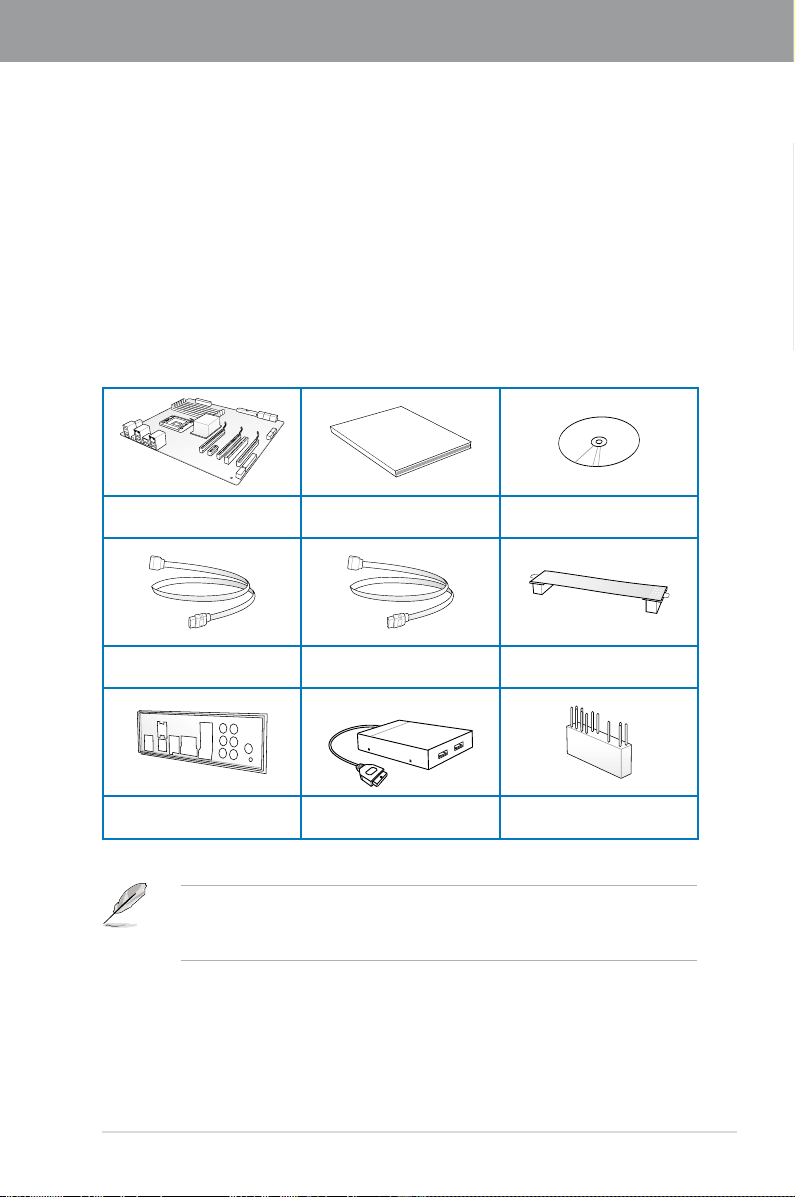
1.2 Package contents
Check your motherboard package for the following items.
Chapter 1
ASUS P8Z68 DELUXE/GEN3
motherboard
4 x Serial ATA 6.0 Gb/s cables 2 x Serial ATA 3.0 Gb/s cables
1 x ASUS Q-Shield
• If any of the above items is damaged or missing, contact your retailer.
• The illustrated items above are for reference only. Actual product specications may
vary with different models.
User guide Support DVD
1 x ASUS front panel
USB 3.0 box
1 x ASUS SLI™ bridge
connector
1 x 2-in-1 ASUS Q-Connector kit
ASUS P8Z68 DELUXE/GEN3 1-1
Page 14

1.3 Special features
1.3.1 Product highlights
Chapter 1
LGA1155 socket for Intel® Second Generation Core™ i7 / Core™ i5 / Core™ i3
Processors
This motherboard supports the Intel® second generation Core™ i7 / Core™ i5 / Core™ i3
processors in LGA1155 package with memory and PCI Express controllers integrated to
support 2-channel (4 DIMMs) DDR3 memory and 16 PCI Express 2.0 lanes. This provides
great graphics performance. Intel® second generation Core™ i7 / Core™ i5 / Core™ i3second generation Core™ i7 / Core™ i5 / Core™ i3
processors are among the most powerful and energy efcient CPUs in the world.
Intel® Z68 Express Chipset
The Intel® Z68 Express Chipset is the latest single-chipset design to support the new 1155
socket Intel® Core™ i7 / Core™ i5 / Core™ i3 second generation processors. It uses serial
point-to-point links, which allows increased bandwidth and stability, and provides an improved
performance. It also provides two SATA 6.0 Gb/s and four SATA 3.0 Gb/s ports for faster
data retrieval at double the bandwidth of current bus systems. Moreover, Intel® Z68 Express
Chipset also supports iGPU function, letting users enjoy the latest Intel integrated graphic
performance.
PCI Express® 3.0
The latest PCI Express bus standard delivers improved encoding for twice the performance
of current PCIe 2.0. Total bandwidth for a x16 link reaches a maximum of 32GB/s, double
the 16GB/s of PCIe 2.0 (in x16 mode). PCIe 3.0 provides users unprecedented data speeds,
combined with the convenience and seamless transition offered by complete backward
compatibility with PCIe 1.0 and PCIe 2.0 devices. It’s a must-have feature for PC users
aiming to improve and optimize graphics performance, as well as have the latest, most
future-proof technology.
* Actual PCIe Speed depends on installed CPU type.
Intel® Smart Response Technology
Intel® Smart Response Technology boosts overall system performance. It uses an installed
fast SSD (min 18.6GB available capacity required) as a cache for frequently accessed data.
Key benets include reduced load and wait times, and lower power consumption through the
elimination of unnecessary hard drive spin. This technology combines SSD performance with
hard drive capacity, operating up to 4X faster than a hard drive-only system, and an important
part of Green ASUS eco-friendly computing.
* Intel® Smart Response Technology supports Windows ® 7/ Vista operating systems.
** Intel® Smart Response Technology is supported by 2nd generation Intel® Core™ processor
family.
*** Operating systems must be installed on the HDD to launch Intel® Smart Response Technology.
The capacity of the SSD is reserved for caching function.
Quad-GPU SLI™ and Quad-GPU CrossFireX™ Support
The motherboard’s powerful Intel® Z68 platform optimizes PCIe allocation in multiple-GPU
congurations of either SLI™ or CrossFireX™. This allows you to enjoy a never before-
experienced brand new gaming style.
1-2 Chapter 1: Product Introduction
Page 15

Dual-Channel DDR3 2200(O.C.) / 2133(O.C.) / 1866(O.C.) / 1600 / 1333 / 1066 Support
The motherboard supports DDR3 memory that features data transfer rates of 2200(O.
C.) / 2133(O.C.) / 1866(O.C.) / 1600 / 1333 / 1066 MHz to meet the higher bandwidth
requirements of the latest 3D graphics, multimedia, and Internet applications. The dualchannel DDR3 architecture enlarges the bandwidth of your system memory to boost system
performance.
* Due to CPU behavior, DDR3 2200/2000/1800 MHz memory module will run at DDR3 2133/1866/1600
MHz frequency as default.
Complete USB 3.0 Integration
ASUS facilitates strategic USB 3.0 accessibility for both the front and rear panel – 4 USB
3.0 ports in total. Experience the latest plug & play connectivity at speeds up to 10 times
faster than USB 2.0. The P8Z68 DELUXE/GEN3 affords greater convenience to high speed
connectivity.
Extra SATA 6.0 Gb/s Support
The Intel® Z68 Express Chipset natively supports the next-generation Serial ATA (SATA)
interface, delivering up to 6.0 Gb/s data transfer. ASUS provides extra SATA 6.0 Gb/s ports
with enhanced scalability, faster data retrieval, and double the bandwidth of current bus
systems.
ASUS Front Panel USB 3.0 Box
ASUS feature-proofs your PC with full USB 3.0 implementation for better computing through
super-fast data transfers. The provided standard-sized USB 3.0 front panel box is compatible
with most PC cases, letting you enjoy the faster throughput of USB 3.0 without relegating
cables and devices to the hard-to-reach rear I/O or having to purchase a new case.
1.3.2 Dual Intelligent Processors 2 with DIGI+ VRM
The world’s rst Dual Intelligent Processors from ASUS pioneered the use of two onboard
chips—EPU (Energy Processing Unit) and TPU (TurboV Processing Unit). New generation
Dual Intelligent Processors 2 with DIGI+ VRM digital power design launch control into a new
era, empowering users with superior exibility and perfect precision to ensure optimized
performance, extreme system stability and greater power efciency.
Chapter 1
DIGI+ VRM
New ASUS DIGI+ VRM upgrades motherboard power delivery to a digital standard. The 16
digital architecture delivers twice the precision power. With iGPU on P8Z68 DELUXE/GEN3
motherboards, DIGI+ VRM intelligently adjust Vcore PWM, integrated graphics voltages
and frequency modulation to minimize power loss through BIOS tuning and the exclusive
user interface. It increases overclocking range while performance reaches its full potential,
adjusting frequencies dynamically and cutting EM interference by half to enhance system
stability through enabled spread spectrum. The DIGI+ VRM digital power design empowers
users with superior exibility and perfect precision to ensure optimized performance. extreme
system stability, and greater power efciency.
ASUS P8Z68 DELUXE/GEN3 1-3
Page 16

2X Precise Power Control
ASUS DIGI+ VRM delivers twice the precision power, intelligently adjusting PWM voltage and
Chapter 1
frequency modulation to minimize power loss while performance reaches its full potential.
2X Less Radiation
ASUS DIGI+ VRM adjusts frequencies dynamically, cutting radiation by half to enhance
system stability through enabling spread spectrum.
TPU
Unleash your performance with ASUS’ simple onboard switch or AI Suite II utility. The TPU
chip offers precise voltage control and advanced monitoring through Auto Tuning and TurboV
functions. Auto tuning offers a user friendly way to automatically optimize the system for fast,
yet stable clock speeds, while TurboV enables unlimited freedom to adjust CPU frequencies
and ratios for optimized performance in diverse situations.
EPU
Tap into the world’s rst real-time PC power saving chip through a simple onboard switch or
AI Suite II utility. Get total system-wide energy optimization by automatically detecting current
PC loadings and intelligently moderating power consumption. This also reduces fan noise
and extends component longevity.
1.3.3 ASUS Exclusive Features
BT GO! (Bluetooth)
Onboard Bluetooth wireless design enables smart connectivity to Bluetooth devices with
no additional adapter. ASUS BT GO! comes with 7 special functions that offer signicant
breakthrough in Bluetooth evolution, including Folder Sync, BT Transfer, BT Turbo Remote,
BT-to-Net, Music Player, Shot and Send, and Personal Manager. All are accessible through
the exclusive, user-friendly ASUS interface.
MemOK!
MemOK! quickly ensures memory boot compatibility. This remarkable memory rescue tool
requires a mere push of a button to patch memory issues. MemOK! determines failsafe
settings and dramatically improves your system boot success.
AI Suite II
With its user-friendly interface, ASUS AI Suite II consolidates all the exclusive ASUS features
into one simple to use software package. It allows you to supervise overclocking, energy
management, fan speed control, voltage and sensor readings, and even interact with mobile
devices via Bluetooth. This all-in-one software offers diverse and ease to use functions, with
no need to switch back and forth between different utilities.
1-4 Chapter 1: Product Introduction
Page 17

1.3.4 ASUS Quiet Thermal Solution
ASUS Fanless Design—Heat-pipe solution
The ASUS heat-pipe features 0-dB thermal solution that offers you a noiseless PC
environment. Its beautiful shape upgrades the visual enjoyment and the heat-pipe design
lowers the temperature of the chipset and power phase area through high efcient heat-
exchange. Combined with usability and aesthetics, the ASUS heat-pipe gives you an
extremely silent and cooling experience with its elegant appearance.
DO NOT uninstall the heat-pipe by yourself. Doing so may bend the tubing and affect the
heat dissipation performance.
ASUS Fan Xpert
ASUS Fan Xpert intelligently allows you to adjust both the CPU and chassis fan speeds
according to different ambient temperatures caused by different climate conditions in different
geographic regions and your PC’s loading. The built-in variety of useful proles offer exible
controls of fan speed to achieve a quiet and cool environment.
1.3.5 ASUS EZ DIY
ASUS UEFI BIOS (EZ Mode)
ASUS UEFI BIOS offers a user-friendly interface that goes beyond traditional keyboard-only
BIOS controls to enable more exible and convenient mouse input. Users can easily navigate
the UEFI BIOS with the smoothness of their operating system. Quick and simple overclocking
and setup sharing is facilitated by the F12 hotkey BIOS snapshot feature. The exclusive EZ
Mode displays frequently-accessed setup info, while the Advanced Mode is for experienced
performance enthusiasts that demand far more intricate system control, including detailed
DRAM information.
Supports hard drives over 2.2TB
ASUS UEFI BIOS natively supports hard drives larger than 2.2TB in 64-bit, with full storage
space utilization helping deliver far more exciting computing than traditional BIOS versions.
ASUS Q-Design
ASUS Q-Design enhances your DIY experience. All of Q-LED, Q-Slot, Q-Code and Q-DIMM
design speed up and simplify the DIY process!
Chapter 1
ASUS Q-Shield
The specially designed ASUS Q-Shield does without the usual "ngers" - making it
convenient and easy to install. With better electric conductivity, it ideally protects your
motherboard against static electricity and shields it against Electronic Magnetic Interference
(EMI).
ASUS Q-Connector
ASUS Q-Connector allows you to easily connect or disconnect the chassis front panel cables
to the motherboard. This unique module eliminates the trouble of connecting the system
panel cables one at a time and avoiding wrong cable connections.
ASUS P8Z68 DELUXE/GEN3 1-5
Page 18

ASUS EZ-Flash 2
ASUS EZ Flash 2 is a user-friendly utility that allows you to update the BIOS without using a
Chapter 1
bootable oppy disk or an OS-based utility.
1.3.6 Other special features
LucidLogix® Virtu
LucidLogix® Virtu is designed for the Intel® Sandy Bridge platform's powerful integrated
graphics. Its GPU virtualization dynamically assigns tasks to the best available graphics
resources based on power, performance and system load on Windows® 7 based PCs. It
allows users to fully utilize the unique capabilities of advanced Sandy Bridge multimedia
features alongside the high end 3D rendering performance provided by installed graphics
cards. When no discrete graphics are needed, the graphics card is put in idle mode to lower
utilization, heat, fan speed and power draw down to near zero, making the system more
environmentally-friendly. For users with diverse needs, LucidLogix® Virtu GPU virtualization
provides great exibility and efciency.
*LucidLogix® Virtu TM supports Windows® 7 operating system.
**Intel® Quick Sync Video feature is supported by 2nd generation Intel® Core™ processor family.
Power eSATA on the Go
The Power eSATA solution combines the eSATA connector and power source together,
allowing you to use external SATA devices without the need of additional power source*.
Easily backup photos, videos and other entertainment contents on external devices.
* Power eSATA requires a specially designed signal cable to provide 5V power for the external
SATA device. The cable is purchased separately.
DTS Surround Sensation UltraPC
DTS Surround Sensation UltraPC delivers exceptional 5.1 surround experience through the
most common PC audio setups—your existing stereo speakers or headphones. In addition
to virtual surround, “Bass enhancement” provides stronger low frequency bass sound, and
“Voice clarication” provides clear human dialogue even with loud background sound. With
these technologies, you may experience a better home-theater audio with ease.
1-6 Chapter 1: Product Introduction
Page 19

Chapter 2
Chapter 2: Hardware information
2.1 Before you proceed
Take note of the following precautions before you install motherboard components or change
any motherboard settings.
• Unplug the power cord from the wall socket before touching any component.
• Before handling components, use a grounded wrist strap or touch a safely grounded
object or a metal object, such as the power supply case, to avoid damaging them due
to static electricity.
• Hold components by the edges to avoid touching the ICs on them.
• Whenever you uninstall any component, place it on a grounded antistatic pad or in the
bag that came with the component.
• Before you install or remove any component, ensure that the ATX power supply is
switched off or the power cord is detached from the power supply. Failure to do so
may cause severe damage to the motherboard, peripherals, or components.
ASUS P8Z68 DELUXE/GEN3 2-1
Page 20
2.2 Motherboard overview
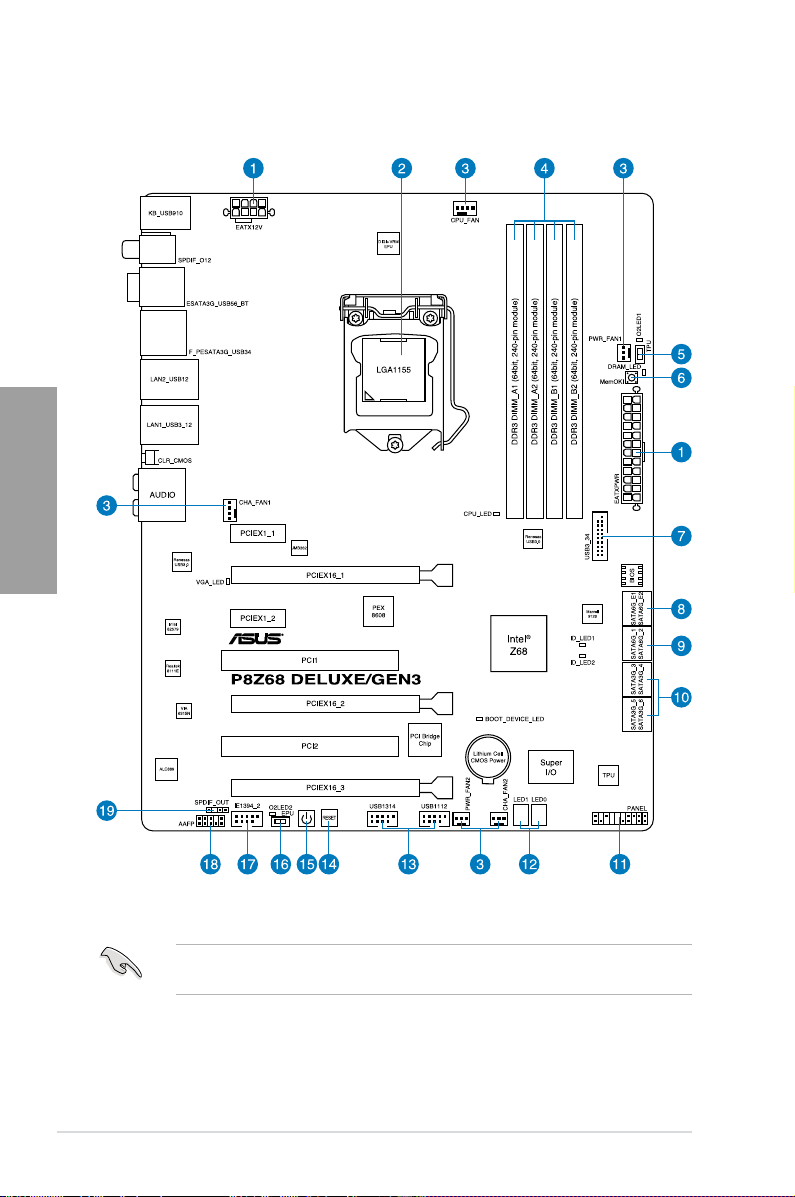
2.2.1 Motherboard layout
Chapter 2
Refer to
2.2.7 Internal connectors
information about rear panel connectors and internal connectors.
2-2 Chapter 2: Hardware information
and
2.3.10 Rear panel connection
for more
Page 21

Layout contents
Connectors/Jumpers/Slots Page
1. ATX power connectors (24-pin EATXPWR, 8-pin EATX12V) 2-31
2. LGA1155 CPU socket 2-4
3. CPU, chassis, and power fan connectors (4-pin CPU_FAN,
4-pin CHA_FAN1, 3-pin CHA_FAN2, 3-pin PWR_FAN1–2)
4. DDR3 DIMM slots 2-5
5. TPU switch 2-17
6. MemOK! switch 2-16
7. USB 3.0 connector (20-1 pin USB3_34) 2-28
8. Marvell® Serial ATA 6.0 Gb/s connectors
(7-pin SATA6G_E1/E2 [navy blue])
9. Intel® Z68 Serial ATA 6.0 Gb/s connectors
(7-pin SATA6G_1/2 [gray])
10. Intel® Z68 Serial ATA 3.0 Gb/s connectors
(7-pin SATA3G_3–6 [blue])
11. System panel connector (20-8 pin PANEL) 2-33
12. Q-Code LED (LED1, LED2) 2-21
13. USB 2.0 connectors (10-1 pin USB1112, USB1314) 2-28
14. Reset switch 2-15
15. Power-on switch 2-15
16. EPU switch 2-18
17. IEEE 1394a port connector (10-1 pin IE1394_2) 2-29
18. Front panel audio connector (10-1 pin AAFP) 2-31
19. Digital audio connector (4-1 pin SPDIF_OUT) 2-29
2-30
2-27
2-25
2-26
Chapter 2
ASUS P8Z68 DELUXE/GEN3 2-3
Page 22
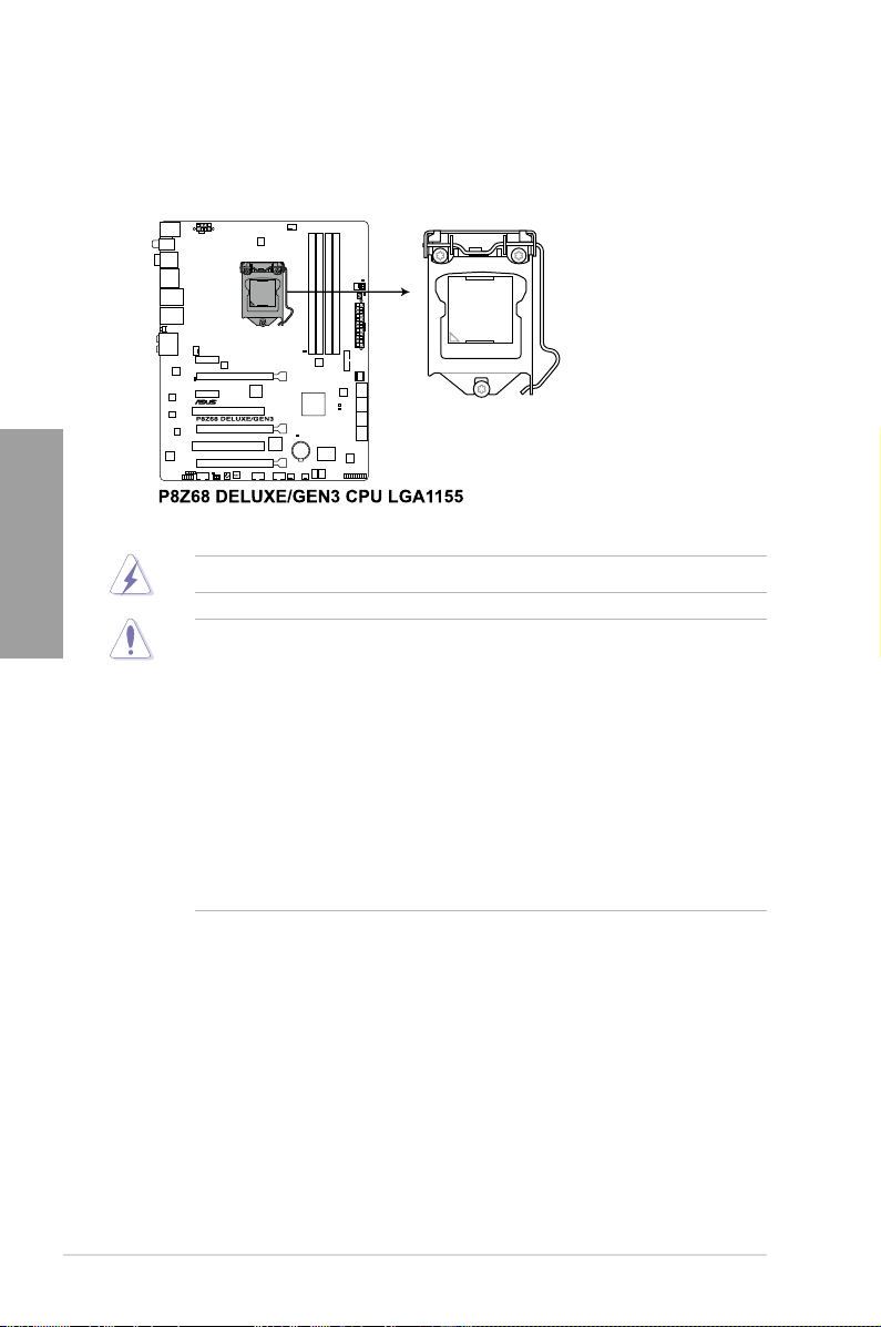
2.2.2 Central Processing Unit (CPU)
The motherboard comes with a surface mount LGA1155 socket designed for the Intel®
2nd Generation Core™ i7 / Core™ i5 / Core™ i3
Chapter 2
/ Pentium / Celeron Processors
Ensure that all power cables are unplugged before installing the CPU.
• The LGA1156 CPU is incompatible with the LGA1155 socket. DO NOT install a
LGA1156 CPU on the LGA1155 socket.
• Upon purchase of the motherboard, ensure that the PnP cap is on the socket and
the socket contacts are not bent. Contact your retailer immediately if the PnP cap
is missing, or if you see any damage to the PnP cap/socket contacts/motherboard
components. ASUS will shoulder the cost of repair only if the damage is shipment/
transit-related.
• Keep the cap after installing the motherboard. ASUS will process Return Merchandise
Authorization (RMA) requests only if the motherboard comes with the cap on the
LGA1155 socket.
• The product warranty does not cover damage to the socket contacts resulting from
incorrect CPU installation/removal, or misplacement/loss/incorrect removal of the PnP
cap.
.
2-4 Chapter 2: Hardware information
Page 23
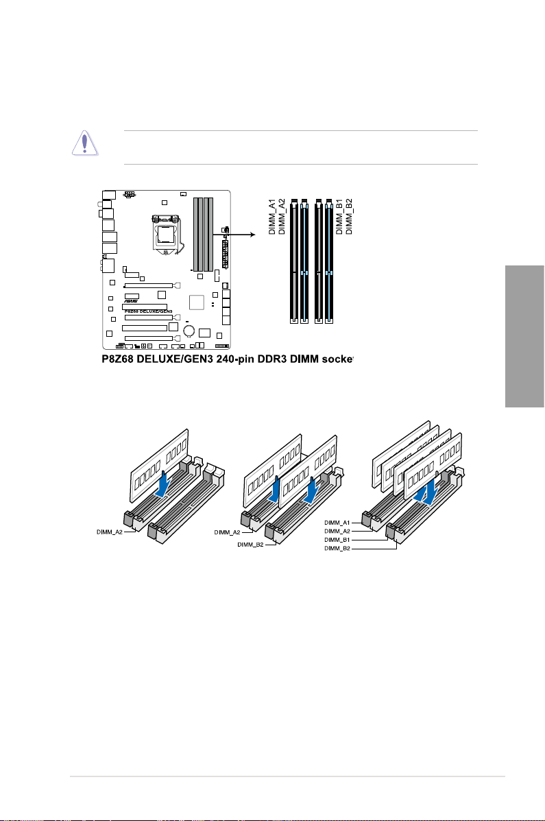
2.2.3 System memory
The motherboard comes with four Double Data Rate 3 (DDR3) Dual Inline Memory Modules
(DIMM) slots.
A DDR3 module is notched differently from a DDR or DDR2 module. DO NOT install a DDR
or DDR2 memory module to the DDR3 slot.
Recommended memory congurations
Chapter 2
ASUS P8Z68 DELUXE/GEN3 2-5
Page 24
Memory congurations
You may install 1GB, 2GB, 4GB and 8GB unbuffered and non-ECC DDR3 DIMMs into the
DIMM sockets.
Chapter 2
• You may install varying memory sizes in Channel A and Channel B. The system maps
the total size of the lower-sized channel for the dual-channel conguration. Any excess
memory from the higher-sized channel is then mapped for single-channel operation.
• Due to CPU behavior, DDR3 2200/2000/1800 MHz memory module will run at DDR3
2133/1866/1600 MHz frequency as default.
• According to Intel CPU spec, DIMM voltage below 1.65V is recommended to protect
the CPU.
• Always install DIMMs with the same CAS latency. For optimum compatibility, we
recommend that you obtain memory modules from the same vendor.
• Due to the memory address limitation on 32-bit Windows OS, when you install 4GB
or more memory on the motherboard, the actual usable memory for the OS can be
about 3GB or less. For effective use of memory, we recommend that you do any of the
following:
- Use a maximum of 3GB system memory if you are using a 32-bit Windows OS.
- Install a 64-bit Windows OS when you want to install 4GB or more on the
motherboard.
For more details, refer to the Microsoft® support site at
http://support.microsoft.com/kb/929605/en-us.
• This motherboard does not support DIMMs made up of 512Mb (64MB) chips or less
(Memory chip capacity counts in Megabit, 8 Megabit/Mb = 1 Megabyte/MB).
• The default memory operation frequency is dependent on its Serial Presence Detect
(SPD), which is the standard way of accessing information from a memory module.
Under the default state, some memory modules for overclocking may operate at a
lower frequency than the vendor-marked value. To operate at the vendor-marked
or at a higher frequency, refer to section
3.4 Ai Tweaker menu
for manual memory
frequency adjustment.
• For system stability, use a more efcient memory cooling system to support a full
memory load (4 DIMMs) or overclocking condition.
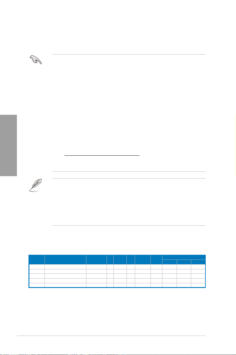
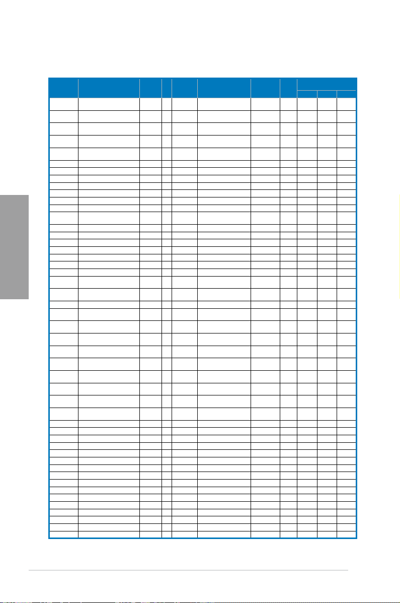
P8Z68 DELUXE/GEN3 Motherboard Qualied Vendors Lists (QVL)
DDR3 2200(O.C.) MHz capability
Vendors Part No. Size
G.SKILL F3-17600CL7D-4GBFLS(XMP) 4GB (2 x 2GB) DS - - 7-10-10-28 1.65 • • •
G.SKILL F3-17600CL8D-4GBPS(XMP) 4GB (2 x 2GB) DS - - 8-8-8-24 1.65 • •
G.SKILL F3-17600CL9D-4GBTDS(XMP) 4GB (2 x 2GB) DS - - 9-9-9-24 1.65 • •
KINGMAX FLKE85F-B8KHA(XMP) 4GB (2 x 2GB) DS - - - 1.5~1.7 • •
KINGMAX FLKE85F-B8KJAA-FEIS(XMP) 4GB (2 x 2GB) DS Kingmax N/A - - • •
SS/DSChip
Brand
Chip
Timing Voltage
NO.
* The memory modules in 2200MHz and above are supported by this motherboard; however, the
actual frequency support varies depending on the O.C. margin of the installed CPU.
2-6 Chapter 2: Hardware information
DIMM socket support (Optional)
1 DIMM 2 DIMM 4 DIMM
Page 25
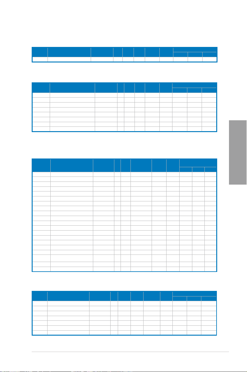
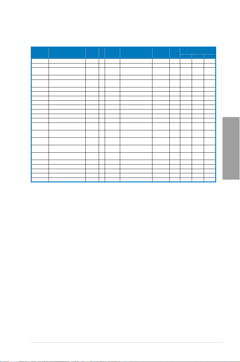
P8Z68 DELUXE/GEN3 Motherboard Qualied Vendors Lists (QVL)
DDR3 2133(O.C.) MHz capability
Vendor Part No. Size
G.SKILL F3-17600CL9D-4GBTDS(XMP) 4GB(2 x 2GB) DS - - 9-9-9-24 1.65 • •
SS/DSChip
Brand
Chip
NO.
Timing Voltage
* The above QVL is for the DDR3 2200 MHz memory module. Due to CPU behavior, DDR3 2200 MHz
memory module will run at DDR3 2133 MHz frequency.
SS/DSChip
Vendor Part No. Size
G.SKILL F3-17066CL9D-4GBTDS(XMP) 4GB ( 2x 2GB ) DS - - - 1.65 • • •
G.SKILL F3-17066CL8D-4GBPS(XMP) 4GB(2 x 2GB) DS - - 8-8-8-24 1.65 • •
G.SKILL F3-17066CL9D-4GBTD(XMP) 4GB(2 x 2GB) DS - - 9-9-9-24 1.65 • •
G.SKILL F3-17066CL9T-6GB-T 6GB(3 x 2GB) DS - - 9-9-9-24 1.65 • •
GEIL GE34GB2133C9DC(XMP) 4GB(2 x 2GB) DS - - 9-9-9-28 1.65 • •
GEIL GU34GB2133C9DC(XMP) 4GB(2 x 2GB) DS - - 9-9-9-28 1.65 • •
KINGSTON KHX2133C9D3T1K2/4GX(XMP) 4GB(2 x 2GB) DS - - 9 1.65 • • •
Patriot PVV34G2133C9K(XMP) 4GB ( 2x 2GB ) DS - - 9-11-9-27 1.66 • • •
Brand
Chip
Timing Voltage
NO.
DIMM socket support (Optional)
1 DIMM 2 DIMM 4 DIMM
DIMM socket support (Optional)
1 DIMM 2 DIMM 4 DIMM
P8Z68 DELUXE/GEN3 Motherboard Qualied Vendors Lists (QVL)
DDR3 1866(O.C.) MHz capability
Vendor Part No. Size
Apacer 78.AAGD5.9KD(XMP) 6GB(3 x 2GB) DS - - 9-9-9-27 - • • •
CORSAIR CMT6GX3M3A2000C8(XMP) 6GB ( 3x 2GB ) DS - - 8-9-8-24 1.65 • • •
Crucial BL12864BE2009.8SFB3(EPP) 1GB SS - - 9-9-9-28 2 • •
G.SKILL F3-16000CL6Q-8GBPIS(XMP) 8GB ( 4x 2GB ) SS - - 6-9-6-24 1.65 • •
G.SKILL F3-16000CL9D-4GBRH(XMP) 4GB(2 x 2GB) DS - - 9-9-9-24 1.65 • • •
G.SKILL F3-16000CL9D-4GBTD(XMP) 4GB(2 x 2GB) DS - - 9-9-9-24 1.65 • • •
G.SKILL F3-16000CL7T-6GBPS(XMP) 6GB(3 x 2GB) DS - - 7-8-7-20 1.65 • •
G.SKILL F3-16000CL9T-6GBPS(XMP) 6GB(3 x 2GB) DS - - 9-9-9-24 1.65 • •
G.SKILL F3-16000CL9T-6GBTD(XMP) 6GB(3 x 2GB) DS - - 9-9-9-24 1.6 • • •
G.SKILL F3-16000CL7Q-8GBFLS(XMP) 8GB(4 x 2GB) DS - - 7-9-7-24 1.65 • •
GEIL GU34GB2000C9DC(XMP) 4GB(2 x 2GB) DS - - 9-9-9-28 2 • •
GEIL GE38GB2000C9QC(XMP) 8GB(4 x 2GB) DS - - 9-9-9-28 1.65 • •
KINGSTON KHX2000C9D3T1K2/4GX(XMP) 4GB ( 2x 2GB ) DS - - - 1.65 • • •
Transcend N/A(XMP) 6GB ( 3x 2GB ) DS - - - - • •
Gingle 9CAASS37AZZ01D1 2GB DS - - 9-9-9-24 - • • •
Patriot PVT36G2000LLK(XMP) 6GB(3 x 2GB) DS - - 8-8-8-24 1.65 • •
Slicon Power SP002GBLYU200S02(XMP) 2GB DS - - - - • •
Team TXD32048M2000C9(XMP) 2GB DS Team T3D1288RT-20 9-9-9-24 1.5 • •
Team TXD32048M2000C9-L(XMP) 2GB DS Team T3D1288LT-20 9-9-9-24 1.5 • •
Team TXD32048M2000C9-L(XMP) 2GB DS Team T3D1288RT-20 9-9-9-24 1.6 • • •
SS/DSChip
Chip NO. Timing Voltage
Brand
* The above QVL is for the DDR3 2000 MHz memory module. Due to CPU behavior, DDR3 2000 MHz
memory module will run at DDR3 1866 MHz frequency.
DIMM socket support
(Optional)
1 DIMM 2 DIMM 4 DIMM
Chapter 2
Vendor Part No. Size
CORSAIR CMT6GX3M3A1866C9(XMP) 6GB ( 3x 2GB ) DS - - 9-9-9-24 1.65 • • •
CORSAIR TR3X6G1866C9DVer4.1(XMP) 6GB(3 x 2GB) DS - - 9-9-9-24 1.65 • •
G.SKILL F3-15000CL9D-4GBRH (XMP) 4GB(2 x 2GB) DS - - 9-9-9-24 1.65 • • •
G.SKILL F3-15000CL9D-4GBTD(XMP) 4GB(2 x 2GB) DS - - 9-9-9-24 1.65 • • •
OCZ OCZ3P1866LV4GK 4GB(2 x 2GB) DS - - 9-9-9 1.65 • •
OCZ OCZ3P1866C9LV6GK 6GB(3 x 2GB) DS - - 9-9-9 1.65 • • •
OCZ OCZ3RPR1866C9LV6GK 6GB(3 x 2GB) DS - - 9-9-9 1.65 • •
SS/DSChip
Brand
Chip
NO.
Timing Voltage
DIMM socket support (Optional)
1 DIMM 2 DIMM 4 DIMM
ASUS P8Z68 DELUXE/GEN3 2-7
Page 26
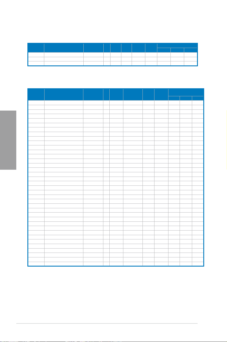
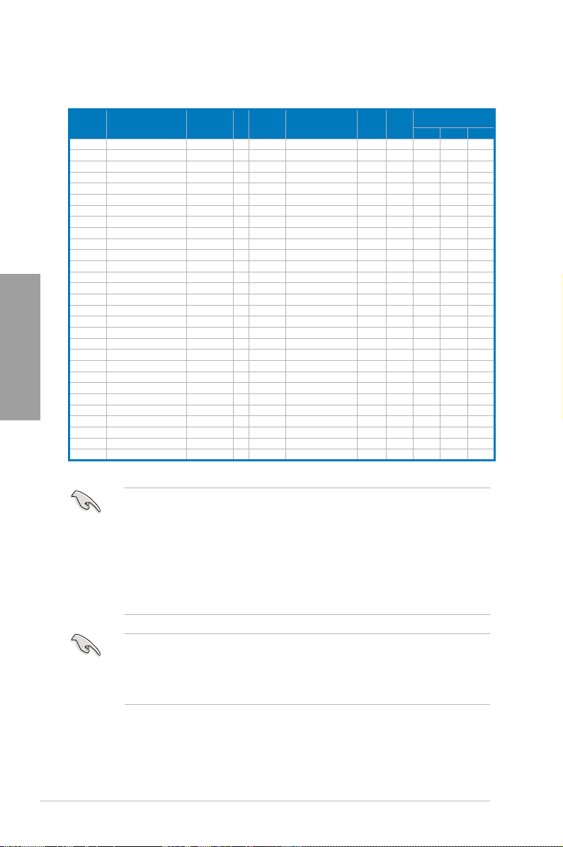
P8Z68 DELUXE/GEN3 Motherboard Qualied Vendors Lists (QVL)
DDR3 1600 MHz capability
Vendor Part No. Size
G.SKILL F3-14400CL6D-4GBFLS(XMP) 4GB(2 x 2GB) DS - - 6-8-6-24 1.65 • •
F3-14400CL9D-4GBRL(XMP) 4GB(2 x 2GB)
G.SKILL
KINGSTON KHX1800C9D3T1K3/6GX(XMP) 6GB(3 x 2GB) DS - - - 1.65 • •
SS/DSChip
DS -
Brand
Chip
NO.
-
Timing Voltage
9-9-9-24 1.6
* The above QVL is for the DDR3 1800 MHz memory module. Due to CPU behavior, DDR3 1800 MHz
memory module will run at DDR3 1600 MHz frequency.
DIMM socket support (Optional)
1 DIMM 2 DIMM 4 DIMM
• •
•
Vendor Part No. Size
A-DATA AX3U1600GC4G9-2G 8GB ( 2x 4GB ) DS - - 9-9-9-24 1.55~1.75 • • •
CORSAIR TR3X3G1600C8DVer2.1(XMP) 3GB(3 x 1GB) SS - - 8-8-8-24 1.65 • • •
CORSAIR CMG4GX3M2A1600C6 4GB ( 2x 2GB ) DS - - 6-6-6-18 1.65 • • •
CORSAIR CMD4GX3M2B1600C8 4GB( 2x 2GB ) DS - - 8-8-8-24 1.65 • • •
Chapter 2
CORSAIR CMG4GX3M2A1600C6 4GB( 2x 2GB ) DS - - 6-6-6-18 1.65 • •
CORSAIR CMX4GX3M2A1600C8(XMP) 4GB( 2x 2GB ) DS - - 8-8-8-24 1.65 • • •
CORSAIR CMD4GX3M2A1600C8(XMP) 4GB(2 x 2GB) DS - - 8-8-8-24 1.65 • • •
CORSAIR CMG4GX3M2A1600C7(XMP) 4GB(2 x 2GB) DS - - 7-7-7-20 1.65 • •
CORSAIR CMX4GX3M2A1600C9(XMP) 4GB(2 x 2GB) DS - - 9-9-9-24 1.65 • • •
CORSAIR TR3X6G1600C8D 6GB(3 x 2GB) DS - - 8-8-8-24 1.65 • •
CORSAIR CMX8GX3M4A1600C9(XMP) 8GB(4 x 2GB) DS - - 9-9-9-24 1.65 • •
Crucial BL12864BN1608.8FF(XMP) 2GB( 2x 1GB ) SS - - 8-8-8-24 1.65 • • •
Crucial BL25664BN1608.16FF(XMP) 2GB DS - - 8-8-8-24 1.65 • • •
G.SKILL F3-12800CL9D-4GBNG 4GB( 2x 2GB ) SS - - - 1.6 • • •
G.SKILL F3-12800CL9D-4GBRL 4GB(2 x 2GB) SS - - - 1.6 • • •
G.SKILL F3-12800CL7D-4GBRH(XMP) 4GB(2 x 2GB) DS - - 7-7-7-24 1.65 • • •
G.SKILL F3-12800CL8D-4GBRM(XMP) 4GB(2 x 2GB) DS - - 8-8-8-24 1.6 • • •
G.SKILL F3-12800CL9D-4GBECO(XMP) 4GB(2 x 2GB) DS - - 9-9-9-24 1.35 • • •
G.SKILL F3-12800CL8T-6GBPI(XMP) 6GB(3 x 2GB) DS - - 8-8-8-21 1.6~1.65 • •
G.SKILL F3-12800CL9T-6GBNQ 6GB(3 x 2GB) DS - - 9-9-9-24 1.5-1.6 • • •
GEIL GV34GB1600C8DC(XMP) 4GB(2 x 2GB) DS - - 8-8-8-28 1.6 • •
KINGMAX FLGD45F-B8MF7(XMP) 1GB SS - - - • • •
KINGSTON KHX1600C8D3K2/4GX(XMP) 4GB ( 2x 2GB ) DS - - 8 1.65 • • •
OCZ OCZ3P1600EB1G 1GB SS - - 7-6-6-24 - • •
OCZ OCZ3G1600LV3GK 3GB(3 x 1GB) SS - - 8-8-8 1.65 • • •
OCZ OCZ3P1600LV3GK 3GB(3 x 1GB) SS - - 7-7-7 1.65 • • •
OCZ OCZ3BE1600C8LV4GK 4GB( 2x 2GB ) DS - - 8-8-8 1.65 • •
OCZ OCZ3BE1600C8LV4GK 4GB( 2x 2GB ) DS - - 8-8-8 1.65 • • •
OCZ OCZ3P1600LV4GK 4GB(2 x 2GB) DS - - 7-7-7 1.65 • •
OCZ OCZ3X1600LV4GK(XMP) 4GB(2 x 2GB) DS - - 8-8-8 1.65 • • •
OCZ OCZ3FXE1600C7LV6GK 6GB ( 3x 2GB ) DS - - 7-7-7 1.65 • •
OCZ OCZ3FXE1600C7LV6GK 6GB(3 x 2GB) DS - - 7-7-7 1.65 • •
OCZ OCZ3G1600LV6GK 6GB(3 x 2GB) DS - - 8-8-8 1.65 • •
OCZ OCZ3X1600LV6GK(XMP) 6GB(3 x 2GB) DS - - 8-8-8 1.65 • • •
OCZ OCZ3X1600LV6GK(XMP) 6GB(3 x 2GB) DS - - 8-8-8 1.65 • • •
Super Talent WP160UX4G9(XMP) 4GB(2 x 2GB) DS - - 9 - • • •
Super Talent WB160UX6G8(XMP) 6GB(3 x 2GB) DS - - - - • • •
SS/DSChip
Brand
Chip NO. Timing Voltage
DIMM socket support
(Optional)
1 DIMM 2 DIMM 4 DIMM
2-8 Chapter 2: Hardware information
Page 27
P8Z68 DELUXE/GEN3 Motherboard Qualied Vendors Lists (QVL)
DDR3 1600 MHz capability (continued)
Vendor Part No. Size
Super Talent WB160UX6G8(XMP) 6GB(3 x 2GB) DS - - 8 - • • •
EK Memory EKM324L28BP8-I16(XMP)
EK Memory EKM324L28BP8-I16(XMP) 4GB(2 x 2GB) DS - - 9 - • • •
GoodRam GR1600D364L9/2G 2GB DS GoodRam GF1008KC-JN - - • • •
KINGTIGER KTG2G1600PG3(XMP) 2GB DS - - - - • • •
Mushkin 996805(XMP) 4GB ( 2x 2GB ) DS - - 6-8-6-24 1.65 • •
Mushkin 996657 4GB(2 x 2GB) DS - - 7-7-7-20 - • • •
Mushkin 998805(XMP)
Patriot PVT33G1600ELK 3GB(3 x 1GB) SS - - 9-9-9-24 1.65 • •
Patriot PGS34G1600LLKA2 4GB ( 2x 2GB ) DS - - 8-8-8-24 1.7 • • •
Patriot PGS34G1600LLKA 4GB( 2x 2GB ) DS - - 7-7-7-20 1.7 • • •
PATRIOT PGS34G1600LLKA 4GB(2 x 2GB) DS - - 7-7-7-20 1.7 • • •
Patriot PVS34G1600ELK 4GB(2 x 2GB) DS - - 9-9-9-24 1.8 • •
PVS34G1600LLK(XMP) 4GB(2 x 2GB)
Patriot
PVS34G1600LLKN 4GB(2 x 2GB) DS - - 7-7-7-20 2.0 • •
Patriot
Patriot PVT36G1600ELK 6GB(3 x 2GB) DS - - 9-9-9-24 1.65 • • •
Patriot PVT36G1600ELK 6GB(3 x 2GB) DS - - 9-9-9-24 1.65 • • •
Patriot PVT36G1600LLK(XMP) 6GB(3 x 2GB) DS - - 8-8-8-24 1.65 • •
4GB( 2x 2GB ) DS
6GB ( 3x 2GB ) DS
SS/DSChip
Brand
-
-
- -
DS
Chip NO. Timing Voltage
- 9
- 6-8-6-24
7-7-7-20 1.9
DIMM socket support
(Optional)
1 DIMM 2 DIMM 4 DIMM
- •
1.65 •
•
•
•
•
•
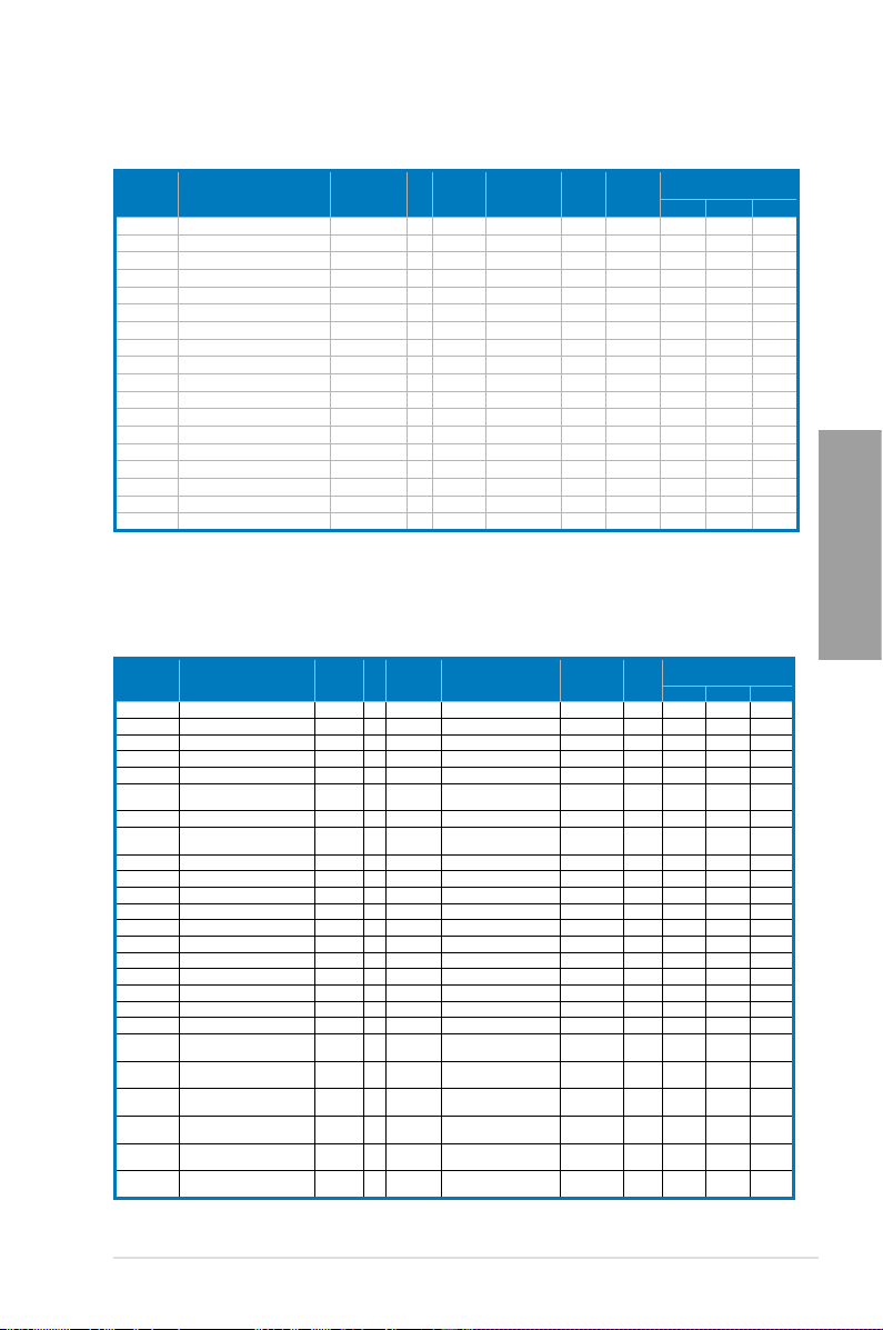
P8Z68 DELUXE/GEN3 Motherboard Qualied Vendors Lists (QVL)
DDR3 1333 MHz capability
Vendor Part No. Size
A-DATA SU3U1333W8G9-B 8GB DS Elpida J4208BASE-DJ-F 9 - • • •
A-DATA SU3U1333B1G9-B 1GB SS Hynix H5TQ1G83TFR - - • • •
A-DATA SU3U1333B2G9-B 2GB DS Hynix H5TQ1G83TFR - - • • •
A-DATA SU3U1333C4G9-B 4GB DS Hynix H5TQ2G83AFR - - • • •
Apacer 78.01GC6.9L0 1GB SS Apacer AM5D5808DEJSBG 9 - • • •
CORSAIR TR3X3G1333C9 (Ver2.1) 3GB(3 x
CORSAIR CM3X1024-1333C9DHX 1GB DS - - - 1.1 • •
CORSAIR CMX8GX3M4A1333C9 8GB(4 x
Crucial CT12864BA1339.8FF 1GB SS MICRON D9KPT 9 - • • •
Crucial CT12864BA1339.8SFD 1GB SS MICRON MT8JF12864AY-1G4D1 - - • • •
Crucial CT12872BA1339.9FF 1GB SS MICRON D9KPT(ECC) 9 - • • •
Crucial BL25664BN1337.16FF(XMP) 2GB DS - - 7-7-7-24 1.65 • • •
Crucial CT25664BA1339.16FF 2GB DS MICRON D9KPT 9 - • • •
Crucial CT25664BA1339.16SFD 2GB DS MICRON D9JNM - - • • •
Crucial CT25672BA1339.18FF 2GB DS MICRON D9KPT(ECC) 9 - • • •
ELPIDA EBJ10UE8BDF0-DJ-F 1GB SS ELPIDA J1108BDSE-DJ-F - - • • •
ELPIDA EBJ10UE8EDF0-DJ-F 1GB SS ELPIDA J1108EDSE-DJ-F - - • • •
ELPIDA EBJ21UE8BAW0-DJ-E 2GB DS ELPIDA J1108BABG-DJ-E 9 - • • •
ELPIDA EBJ21UE8BDF0-DJ-F 2GB DS ELPIDA J1108BDSE-DJ-F - - • • •
G.SKILL F3-10600CL8D-2GBHK 2GB(2 x
G.SKILL F3-10666CL7D-4GBPI(XMP) 4GB(2 x
G.SKILL F3-10666CL7D-4GBRH(XMP) 4GB(2 x
G.SKILL F3-10666CL8D-4GBECO(XMP) 4GB(2 x
G.SKILL F3-10666CL8D-4GBHK(XMP) 4GB(2 x
G.SKILL F3-10666CL8D-4GBRM(XMP) 4GB(2 x
SS/
Chip Brand Chip NO. Timing Voltage
DS
SS - - 9-9-9-24 1.5 • • •
1GB)
DS - - 9-9-9-24 1.5 • • •
2GB)
SS - - - 1.65 • • •
1GB)
DS - - 7-7-7-21 1.5 • • •
2GB)
DS - - 7-7-7-21 1.5 • • •
2GB)
DS - - 8-8-8-24 1.35 • • •
2GB)
DS - - 8-8-8-21 1.5-1.6 • • •
2GB)
DS - - 8-8-8-21 1.5-1.6 • • •
2GB)
DIMM socket support
(Optional)
1 DIMM 2 DIMM 4 DIMM
Chapter 2
ASUS P8Z68 DELUXE/GEN3 2-9
Page 28
P8Z68 DELUXE/GEN3 Motherboard Qualied Vendors Lists (QVL)
DDR3 1333 MHz capability (continued)
Vendor Part No. Size
G.SKILL F3-10666CL9D-8GBRL 8GB ( 2x
GEIL GG34GB1333C9DC 4GB ( 2x
GEIL GB34GB1333C7DC 4GB(2 x
GEIL GG34GB1333C9DC 4GB(2 x
GEIL GV34GB1333C7DC 4GB(2 x
Hynix HMT112U6BFR8C-H9 1GB SS Hynix H5TQ1G83BFR 9 - • • •
Hynix HMT112U6TFR8A-H9 1GB SS Hynix H5TC1G83TFR - - • • •
Hynix HMT125U6BFR8C-H9 2GB DS Hynix H5TQ1G83BFRH9C 9 - • • •
Hynix HMT125U6TFR8A-H9 2GB DS Hynix H5TC1G83TFR - - • • •
KINGMAX FLFE85F-B8KL9 2GB DS KINGMAX KFB8FNLXL-BNF-15A - - • • •
Kingston KVR1333D3N9/1G 1GB SS Elpida J1108BDSE-DJ-F 9 1.5 • • •
Kingston KVR1333D3N9/2G 2GB DS Kingston D1288JPNDPLD9U 9 1.5 • • •
Chapter 2
Kingston KHX1333C9D3UK2/4GX(XMP) 4GB ( 2x
MICRON MT8JTF12864AZ-1G4F1 1GB SS MICRON 9FF22 D9KPT 9 - • • •
MICRON MT8JTF12864AZ-1G4F1 1GB SS MICRON D9KPT 9 - • • •
MICRON MT9JSF12872AZ-1G4F1 1GB SS MICRON D9KPT(ECC) 9 - • • •
MICRON MT16JF25664AZ-1G4F1 2GB DS MICRON D9KPT 9 - • • •
MICRON MT16JTF25664AZ-1G4F1 2GB DS MICRON 9FF22 D9KPT 9 - • • •
MICRON MT18JSF25672AZ-1G4F1 2GB DS MICRON D9KPT(ECC) 9 - • • •
OCZ OCZ3RPX1333EB2GK 1GB SS - - - - • •
OCZ OCZ3G1333LV3GK 3GB(3 x
OCZ OCZ3P1333LV3GK 3GB(3 x
OCZ OCZ3P13332GK 1GB DS - - 7-7-7-20 - • •
OCZ OCZ3G1333ULV4GK 4GB ( 2x
OCZ OCZ3P1333LV4GK 4GB ( 2x
OCZ OCZ3G1333ULV4GK 4GB(2 x
OCZ OCZ3P13334GK 4GB(2 x
OCZ OCZ3P1333LV4GK 4GB(2 x
OCZ OCZ3RPX1333EB4GK 4GB(2 x
OCZ OCZ3G1333LV6GK 6GB(3 x
OCZ OCZ3P1333LV6GK 6GB(3 x
OCZ OCZX1333LV6GK(XMP) 6GB(3 x
PSC AL8F8G73D-DG1 2GB DS PSC A3P1GF3DGF - - • • •
SAMSUNG M378B1G73AH0-CH9 8GB DS SAMSUNG K4B4G0846A-HCH9 - - • • •
SAMSUNG M378B2873DZ1-CH9 1GB SS SAMSUNG K4B1G0846D 9 - • • •
SAMSUNG M378B2873EH1-CH9 1GB SS SAMSUNG K4B1G0846E - - • • •
SAMSUNG M378B2873FHS-CH9 1GB SS SAMSUNG K4B1G0846F - - • • •
SAMSUNG M391B2873DZ1-CH9 1GB SS SAMSUNG K4B1G0846D(ECC) 9 - • • •
SAMSUNG M378B5673DZ1-CH9 2GB DS SAMSUNG K4B1G0846D 9 - • • •
SAMSUNG M378B5673FH0-CH9 2GB DS SAMSUNG K4B1G0846F - - • • •
SAMSUNG M391B5673DZ1-CH9 2GB DS SAMSUNG K4B1G0846D(ECC) 9 - • • •
SAMSUNG M378B5273BH1-CH9 4GB DS SAMSUNG K4B2G0846B-HCH9 9 - • • •
SAMSUNG M378B5273CH0-CH9 4GB DS SAMSUNG K4B2G0846C K4B2G0846C - • • •
Transcend N/A 2GB DS Elpida J1108BDBG-DJ-F - - • • •
ASUS N/A 1GB DS - - - - • •
ATP AQ28M64A8BJH9S 1GB SS SAMSUNG K4B1G0846E - - • • •
ATP AQ28M72D8BJH9S 1GB SS SAMSUNG K4B1G0846D(ECC) - - • • •
ATP AQ56M64B8BJH9S 2GB DS SAMSUNG K4B1G0846D - - • • •
SS/
Chip Brand Chip NO. Timing Voltage
DS
DS - - 9-9-9-24 1.5 • • •
4GB )
DS GEIL GL1L128M88BA115FW 9-9-9-24 1.3 • • •
2GB )
DS GEIL GL1L128M88BA15FW 7-7-7-24 1.5 • • •
2GB)
DS GEIL GL1L128M88BA12N 9-9-9-24 1.3 • • •
2GB)
DS - - 7-7-7-24 1.5 • •
2GB)
DS - - 9 1.25 • • •
2GB )
SS - - 9-9-9 1.65 • •
1GB)
SS - - 7-7-7 1.65 • • •
1GB)
DS - - 8-8-8 1.35 • •
2GB )
DS - - - 1.65 • • •
2GB )
DS - - 8-8-8 1.65 • •
2GB)
DS - - 7 1.8 • •
2GB)
DS - - 7-7-7 1.65 • • •
2GB)
DS - - - 1.85 • •
2GB)
DS - - 9-9-9 1.65 • • •
2GB)
DS - - 7-7-7 1.65 • • •
2GB)
DS NA - 8-8-8 1.6 • • •
2GB)
DIMM socket support
(Optional)
1 DIMM 2 DIMM 4 DIMM
2-10 Chapter 2: Hardware information
Page 29
P8Z68 DELUXE/GEN3 Motherboard Qualied Vendors Lists (QVL)
DDR3 1333 MHz capability (continued)
Vendor Part No. Size
ATP AQ12M72E8BKH9S 4GB DS SAMSUNG K4B2G0846B-HCH9 (ECC) - - • • •
BUFFALO FSX1333D3G-1G 1GB SS - - - - • •
BUFFALO FSH1333D3G-T3G(XMP) 3GB(3 x
BUFFALO FSX1333D3G-2G 2GB DS - - - - • • •
EK Memory EKM324L28BP8-I13 4GB(2 x
Elixir M2F2G64CB88B7N-CG 2GB SS Elixir N2CB2G808N-CG - - • • •
Elixir M2Y2G64CB8HA9N-CG 2GB DS - - - - • • •
Elixir M2Y2G64CB8HC9N-CG 2GB DS - - - - • • •
Elixir M2F4G64CB8HB5N-CG 4GB DS Elixir N2CB2G808N-CG - - • • •
GoodRam GR1333D364L9/2G 2GB DS Qimonda IDSH1G-03A1F1C-13H - - • • •
KINGTIGER F10DA2T1680 2GB DS KINGTIGER KTG1333PS1208NST-C9 - - • • •
KINGTIGER KTG2G1333PG3 2GB DS - - - - • • •
Patriot PDC32G1333LLK 1GB SS PATRIOT - 7 1.7 • •
Patriot PVT33G1333ELK 3GB(3 x
Patriot PGS34G1333LLKA 4GB(2 x
Patriot PVS34G1333ELK 4GB(2 x
Patriot PVS34G1333LLK 4GB(2 x
Patriot PVT36G1333ELK 6GB(3 x
Silicon Power SP001GBLTU1333S01 1GB SS NANYA NT5CB128M8AN-CG - - • • •
Silicon Power SP001GBLTU133S02 1GB SS S-POWER I0YT3E0 9 - • •
Silicon Power SP002GBLTU133S02 2GB DS S-POWER I0YT3E0 9 - • •
Slicon Power SP001GBLTE133S01 1GB SS NANYA NT5CB128M8AN-CG - - • • •
Slicon Power SP002GBLTE133S01 2GB DS NANYA NT5CB128M8AN-CG - - • • •
SS/
Chip Brand Chip NO. Timing Voltage
DS
SS - - 7-7-7-20 - • • •
1GB)
DS - - 9 - • • •
2GB)
SS - - 9-9-9-24 1.65 • • •
1GB)
DS - - 7-7-7-20 1.7 • • •
2GB)
DS - - 9-9-9-24 1.5 • •
2GB)
DS - - 7-7-7-20 1.7 • •
2GB)
DS - - 9-9-9-24 1.65 • • •
2GB)
DIMM socket support
(Optional)
1 DIMM 2 DIMM 4 DIMM
Chapter 2
ASUS P8Z68 DELUXE/GEN3 2-11
Page 30
P8Z68 DELUXE/GEN3 Motherboard Qualied Vendors Lists (QVL)
DDR3 1066 MHz capability
Vendor Part No. Size
Crucial CT12864BA1067.8FF 1GB SS MICRON D9KPT 7 - • • •
Crucial CT12864BA1067.8SFD
Crucial CT12872BA1067.9FF 1GB SS MICRON D9KPT(ECC) 7 - • • •
Crucial CT25664BA1067.16FF 2GB DS MICRON D9KPT 7 - • • •
Crucial CT25664BA1067.16SFD 2GB DS MICRON D9JNL 7 - • • •
Crucial CT25672BA1067.18FF 2GB DS MICRON D9KPT(ECC) 7 - • • •
ELPIDA EBJ10UE8BAW0-AE-E 1GB SS ELPIDA J1108BABG-DJ-E 7 - • • •
ELPIDA EBJ10UE8EDF0-AE-F
ELPIDA EBJ11UD8BAFA-AG-E 1GB DS ELPIDA J5308BASE-AC-E 8 - • •
ELPIDA EBJ21UE8BAW0-AE-E 2GB DS ELPIDA J1108BABG-DJ-E 7 - • • •
ELPIDA EBJ21UE8EDF0-AE-F 2GB DS ELPIDA J1108EDSE-DJ-F - - • • •
GEIL GG34GB1066C8DC 4GB ( 2x 2GB ) DS GEIL GL1L128M88BA115FW 8-8-8-20 1.3 • • •
Hynix HMT112U6AFP8C-G7N0 1GB SS HYNIX H5TQ1G83AFPG7C 7 - • • •
Hynix
Chapter 2
Hynix HMT125U6AFP8C-G7N0 2GB DS HYNIX H5TQ1G83AFPG7C 7 - • • •
Hynix HYMT125U64ZNF8-G7 2GB DS HYNIX HY5TQ1G831ZNFP-G7 7 - • • •
Kingston KVR1066D3N7/1G 1GB SS Kingston D1288JPNDPLD9U 7 1.5 • • •
Kingston KVR1066D3N7/2G 2GB DS Elpida J1108BDSE-DJ-F 7 1.5 • • •
MICRON MT8JTF12864AZ-1G1F1 1GB SS MICRON 8ZF22 D9KPV 7 - • • •
MICRON MT8JTF12864AZ-1G1F1 1GB SS MICRON D9KPT 7 - • • •
MICRON MT9JSF12872AZ-1G1F1 1GB SS MICRON D9KPT(ECC) 7 - • • •
MICRON MT16JTF25664AZ-1G1F1 2GB DS MICRON 8ZF22 D9KPV 7 - • • •
MICRON MT16JTF25664AZ-1G1F1 2GB DS MICRON D9KPT 7 - • • •
MICRON MT18JSF25672AZ-1G1F1 2GB DS MICRON D9KPT(ECC) 7 - • • •
SAMSUNG M378B5273BH1-CF8 4GB DS SAMSUNG K4B2G0846B-HCF8 8 1.5 • • •
Elixir M2Y2G64CB8HA9N-BE 2GB DS - - - - • • •
Elixir M2Y2G64CB8HC5N-BE 2GB DS Elixir N2CB1G80CN-BE - - • • •
Elixir M2Y2G64CB8HC9N-BE 2GB DS - - - - • • •
WINTEC 3DU3191A-10 1GB DS Qimonda IDSH51-03A1F1C-10F 7 - • •
HYMT112U64ZNF8-G7
1GB SS
1GB SS
1GB SS
SS/DSChip
Brand
MICRON
ELPIDA
HYNIX
Chip NO. Timing Voltage
D9JNL 7
J1108EDSE-DJ-F -
HY5TQ1G831ZNFP-G7 7
- •
- •
- •
DIMM socket support
(Optional)
1 DIMM 2 DIMM 4 DIMM
•
•
•
•
•
Side(s): SS - Single-sided DS - Double-sided
DIMM support:
• 1 DIMM:
•
Supports one (1) module inserted into any slot as Single-channel memory
conguration.
Supports two (2) modules inserted into either the blue slots or the black
2 DIMMs:
slots as one pair of Dual-channel memory conguration.
We suggest that you install the module into A2 slot.
We suggest that
you install the modules into slots A2 and B2 for better compatibility.
• 4 DIMMs:
Supports four (4) modules inserted into both the blue and black slots as
two pairs of Dual-channel memory conguration.
• ASUS exclusively provides hyper DIMM support function.
• Hyper DIMM support is subject to the physical characteristics of individual CPUs. Load
the X.M.P. or D.O.C.P. settings in the BIOS for the hyper DIMM support.
• Visit the ASUS website for the latest QVL.
2-12 Chapter 2: Hardware information
Page 31

2.2.4 Expansion slots
Ensure to unplug the power cord before adding or removing expansion cards. Failure to do
so may cause you physical injury and damage motherboard components.
Chapter 2
Slot No. Slot Description
1 PCIe 2.0 x1_1 slot
2 PCIe 3.0/ 2.0 x16_1 slot (single at x16 or dual at x8/x8 mode)
3 PCIe 2.0 x1_2 slot
4 PCI slot 1
5 PCIe 3.0/ 2.0 x16_2 slot (at x8 mode)
6 PCI slot 2
7 PCIe 2.0 x16_3 slot [black] (at x4 mode, compatible with PCIe x1 and x4 devices)
VGA conguration
Single VGA/PCIe card
Dual VGA/PCIe card
ASUS P8Z68 DELUXE/GEN3 2-13
PCI Express operating mode
PCIe 3.0/ 2.0 x16_1 PCIe 3.0/ 2.0 x16_2
x16
(Recommend for single VGA)
x8 x8
N/A
Page 32

IRQ assignments for this motherboard
Chapter 2
Intel PCH SATA
Controller #0
Intel PCH SATA
Controller #1
SMBUS Controller – shared – – – – –
Thermal Controller – shared – – – – –
EHCI #0 – – – – – – – shared
EHCI #1 – – – – – – – shared
PCIE x16_1 shared – – – – – – –
PCIE x16_2 shared – – – – – –
PCIE x16_3 shared – – – – – – –
Renesas Electronics
USB 3.0 #1
Renesas Electronics
USB 3.0 #2
Intel 82579 LAN – shared – – – – – –
PEX PCIE Bridge – – shared – – – –
VIA 6315N shared – – – – – – –
RealTek 8111E – – – shared – – – –
JMicron 362 IDE
Controller
Marvell 9128 Hardware
RAID Controller
PCIE x1_1 – – shared – – – – –
PCIE x1_2 shared – – – – – – –
PCI slot 1 – – shared – – – –
PCI slot 2 shared – – – – – – –
• In single VGA card mode, use the PCIe 3.0/ 2.0 x16_1 slot (navy blue) for a PCI
Express x16 graphics card to get better performance.
• In CrossFireX™ or SLI™ mode, use the PCIe 3.0/ 2.0 x16_1 and PCIe 3.0/ 2.0 x16_2
slots for PCI Express x16 graphics cards to get better performance.
• We recommend that you provide sufcient power when running CrossFireX™ or SLI™
mode. Refer to page 2-31 for details.
• Actual PCIe speed depends on installed CPU type.
• Connect a chassis fan to the motherboard connector labeled CHA_FAN1/2 when using
multiple graphics cards for better thermal environment. See page 2-30 for details.
A B C D E F G H
– – shared – – – – –
– – – shared – – – –
shared – – – – – – –
– – shared – – – – –
shared – – – – – – –
– shared – – – – – –
2-14 Chapter 2: Hardware information
Page 33

2.2.5 Onboard switches
Onboard switches allow you to ne-tune performance when working on a bare or open-
case system. This is ideal for overclockers and gamers who continually change settings to
enhance system performance.
1. Power-on switch
The motherboard comes with a power-on switch that allows you to power up or wake
up the system. The switch also lights up when the system is plugged to a power source
indicating that you should shut down the system and unplug the power cable before
removing or plugging in any motherboard component. The illustration below shows the
location of the onboard power-on switch.
2. Reset switch
Press the reset switch to reboot the system.
Chapter 2
ASUS P8Z68 DELUXE/GEN3 2-15
Page 34

3. MemOK! switch
Installing DIMMs that are incompatible with the motherboard may cause system
boot failure, and the DRAM_LED near the MemOK! switch lights continuously. Press
and hold the MemOK! switch until the DRAM_LED starts blinking to begin automatic
memory compatibility tuning for successful boot.
Chapter 2
• Refer to section
• The DRAM_LED also lights when the DIMM is not properly installed. Turn off the
system and reinstall the DIMM before using the MemOK! function.
• The MemOK! switch does not function under Windows™ OS environment.
• During the tuning process, the system loads and tests failsafe memory settings. It
takes about 30 seconds for the system to test one set of failsafe settings. If the test
fails, the system reboots and test the next set of failsafe settings. The blinking speed
of the DRAM_LED increases, indicating different test processes.
• Due to memory tuning requirement, the system automatically reboots when each
timing set is tested. If the installed DIMMs still fail to boot after the whole tuning
process, the DRAM_LED lights continuously. Replace the DIMMs with ones
recommended in the Memory QVL (Qualied Vendors Lists) in this user manual or on
the ASUS website at www.asus.com.
• If you turn off the computer and replace DIMMs during the tuning process, the system
continues memory tuning after turning on the computer. To stop memory tuning, turn
off the computer and unplug the power cord for about 5–10 seconds.
• If your system fail to boot due to BIOS overclocking, press the MemOK! switch to boot
and load BIOS default settings. A messgae will appear during POST reminding you
that the BIOS has been restored to its default settings.
• We recommend that you download and update to the latest BIOS version from the
ASUS website at www.asus.com after using the MemOK! function.
2.2.6 Onboard LEDs
for the exact location of the DRAM_LED.
2-16 Chapter 2: Hardware information
Page 35

4. TPU switch
Turning this switch to
clock speeds.
will automatically optimize the system for fast, yet stable
Enable
For ensuring the system performance, turn the switch setting to
powered off.
• The TPU LED (O2LED1) near the TPU switch lights when the switch setting is turned
to
. Refer to section
Enable
LED.
• If you change the switch setting to
function will be activated after the next system bootup.
• You may use the TurboV and Auto Tuning feature in the TurboV EVO application,
adjust the BIOS setup program, or enable the TPU switch at the same time. However,
the system will use the last setting you have made.
2.2.6 Onboard LEDs
Enable
for the exact location of the TPU
under the OS environment, the TPU
when the system is
Enable
Chapter 2
ASUS P8Z68 DELUXE/GEN3 2-17
Page 36

5. EPU switch
Turning this switch to
will automatically detect the current PC loadings and
Enable
intelligently moderate the power consumption.
Chapter 2
For ensuring the system performance, turn the switch setting to
powered off.
• The EPU LED (O2LED2) near the EPU switch lights when the switch setting is turned
to
. Refer to section
Enable
LED.
• If you change the switch setting to
function will be activated after the next system bootup.
• You may change the EPU settings in the software application or BIOS setup program,
and enable the EPU function at the same time. However, the system will use the last
setting you have made.
2.2.6 Onboard LEDs
Enable
for the exact location of the EPU
under the OS environment, the EPU
when the system is
Enable
2-18 Chapter 2: Hardware information
Page 37

2.2.6 Onboard LEDs
1. POST State LEDs
The POST State LEDs of CPU, DRAM, VGA card, and HDD indicate key components
status during POST (Power-on Self Test). If an error is found , the LED next to the
error device will continue lighting until the problem is solved. This user-friendly design
provides an intuitional way to locate the root problem within a second.
2. ID LEDs
The ID LEDs provide an elegant embellishment to the motherboard design.
Chapter 2
ASUS P8Z68 DELUXE/GEN3 2-19
Page 38
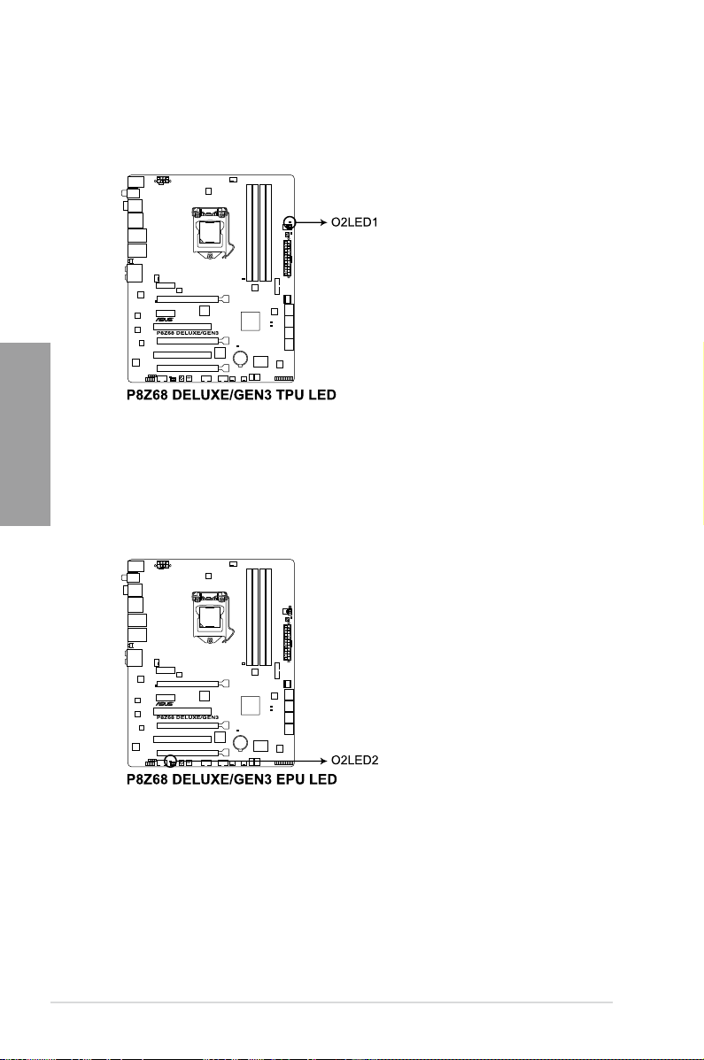
3. TPU LED
The TPU LED lights when the TPU switch is turned to
Chapter 2
4. EPU LED
The EPU LED lights when the EPU switch is turned to
Enable
Enable
.
.
2-20 Chapter 2: Hardware information
Page 39

5. Q-Code LEDs
The Q-Code LED design provides you the 2-digit display, allowing you to know the
system status. Refer to the Q-Code table below for details.
Q-Code table
Code Description
00
01
02
03
04
05
06
07
08
09
0A
0B
0C – 0D
0E
0F
10
11 – 14
15 – 18
19 – 1C
1D – 2A
2B – 2F
30
Not used
Power on. Reset type detection (soft/hard).
AP initialization before microcode loading
System Agent initialization before microcode loading
PCH initialization before microcode loading
OEM initialization before microcode loading
Microcode loading
AP initialization after microcode loading
System Agent initialization after microcode loading
PCH initialization after microcode loading
OEM initialization after microcode loading
Cache initialization
Reserved for future AMI SEC error codes
Microcode not found
Microcode not loaded
PEI Core is started
Pre-memory CPU initialization is started
Pre-memory System Agent initialization is started
Pre-memory PCH initialization is started
OEM pre-memory initialization codes
Memory initialization
Reserved for ASL (see ASL Status Codes section below)
Chapter 2
ASUS P8Z68 DELUXE/GEN3 2-21
Page 40

Q-Code table (continued)
Code Description
31
32 – 36
37 – 3A
3B – 3E
3F – 4E
4F
50 – 53
54
55
56
Chapter 2
57
58
59
5A
5B
5C – 5F
E0
E1
E2
E3
E4 – E7
E8
E9
EA
EB
EC – EF
F0
F1
F2
F3
F4
F5 – F7
F8
F9
FA
FB – FF
60
61
62
Memory Installed
CPU post-memory initialization
Post-Memory System Agent initialization is started
Post-Memory PCH initialization is started
OEM post memory initialization codes
DXE IPL is started
Memory initialization error. Invalid memory type or incompatible memory
speed
Unspecied memory initialization error
Memory not installed
Invalid CPU type or Speed
CPU mismatch
CPU self test failed or possible CPU cache error
CPU micro-code is not found or micro-code update is failed
Internal CPU error
Reset PPI is not available
Reserved for future AMI error codes
S3 Resume is stared (S3 Resume PPI is called by the DXE IPL)
S3 Boot Script execution
Video repost
OS S3 wake vector call
Reserved for future AMI progress codes
S3 Resume Failed
S3 Resume PPI not Found
S3 Resume Boot Script Error
S3 OS Wake Error
Reserved for future AMI error codes
Recovery condition triggered by rmware (Auto recovery)
Recovery condition triggered by user (Forced recovery)
Recovery process started
Recovery rmware image is found
Recovery rmware image is loaded
Reserved for future AMI progress codes
Recovery PPI is not available
Recovery capsule is not found
Invalid recovery capsule
Reserved for future AMI error codes
DXE Core is started
NVRAM initialization
Installation of the PCH Runtime Services
2-22 Chapter 2: Hardware information
Page 41

Q-Code table (continued)
Code Description
63 – 67
68
69
6A
6B – 6F
70
71
72
73 – 77
78
79
7A – 7F
80 – 8F
90
91
92
93
94
95
96
97
98
99
9A
9B
9C
9D
9E – 9F
A0
A1
A2
A3
A4
A5
A6
A7
A8
A9
AA
AB
CPU DXE initialization is started
PCI host bridge initialization
System Agent DXE initialization is started
System Agent DXE SMM initialization is started
System Agent DXE initialization (System Agent module specic)
PCH DXE initialization is started
PCH DXE SMM initialization is started
PCH devices initialization
PCH DXE Initialization (PCH module specic)
ACPI module initialization
CSM initialization
Reserved for future AMI DXE codes
OEM DXE initialization codes
Boot Device Selection (BDS) phase is started
Driver connecting is started
PCI Bus initialization is started
PCI Bus Hot Plug Controller Initialization
PCI Bus Enumeration
PCI Bus Request Resources
PCI Bus Assign Resources
Console Output devices connect
Console input devices connect
Super IO Initialization
USB initialization is started
USB Reset
USB Detect
USB Enable
Reserved for future AMI codes
IDE initialization is started
IDE Reset
IDE Detect
IDE Enable
SCSI initialization is started
SCSI Reset
SCSI Detect
SCSI Enable
Setup Verifying Password
Start of Setup
Reserved for ASL (see ASL Status Codes section below)
Setup Input Wait
Chapter 2
ASUS P8Z68 DELUXE/GEN3 2-23
Page 42

Q-Code table (continued)
Code Description
AC
AD
AE
AF
B0
B1
B2
B3
B4
B5
B6
Chapter 2
B7
B8– BF
C0– CF
D0
D1
D2
D3
D4
D5
D6
D7
D8
D9
DA
DB
DC
Reserved for ASL (see ASL Status Codes section below)
Ready To Boot event
Legacy Boot event
Exit Boot Services event
Runtime Set Virtual Address MAP Begin
Runtime Set Virtual Address MAP End
Legacy Option ROM Initialization
System Reset
USB hot plug
PCI bus hot plug
Clean-up of NVRAM
Conguration Reset (reset of NVRAM settings)
Reserved for future AMI codes
OEM BDS initialization codes
CPU initialization error
System Agent initialization error
PCH initialization error
Some of the Architectural Protocols are not available
PCI resource allocation error. Out of Resources
No Space for Legacy Option ROM
No Console Output Devices are found
No Console Input Devices are found
Invalid password
Error loading Boot Option (LoadImage returned error)
Boot Option is failed (StartImage returned error)
Flash update is failed
Reset protocol is not available
ACPI/ASL Checkpoints
Code Description
0x01
0x02
0x03
0x04
0x05
0x10
0x20
0x30
0x40
0xAC
0xAA
2-24 Chapter 2: Hardware information
System is entering S1 sleep state
System is entering S2 sleep state
System is entering S3 sleep state
System is entering S4 sleep state
System is entering S5 sleep state
System is waking up from the S1 sleep state
System is waking up from the S2 sleep state
System is waking up from the S3 sleep state
System is waking up from the S4 sleep state
System has transitioned into ACPI mode. Interrupt controller is in PIC mode.
System has transitioned into ACPI mode. Interrupt controller is in APIC mode.
Page 43

2.2.7 Internal connectors
1. Intel® Z68 Serial ATA 6.0 Gb/s connectors (7-pin SATA6G_1/2 [gray])
These connectors connect to Serial ATA 6.0 Gb/s hard disk drives via Serial ATA 6.0
Gb/s signal cables.
If you installed Serial ATA hard disk drives, you can create a RAID 0, 1, 5, and 10
conguration with the Intel® Rapid Storage Technology through the onboard Intel® Z68
chipset.
Chapter 2
•
These connectors are set to [AHCI Mode] by default. If you intend to create a Serial
ATA RAID set using these connectors, set the SATA Mode item in the BIOS to [RAID
Mode]. Refer to section 3.5.4 SATA Conguration for details.
• Before creating a RAID set, refer to section 4.4 RAID congurations or the manual
bundled in the motherboard support DVD.
•
When using NCQ, set the
3.5.4 SATA Conguration
•
You must install Windows® XP Service Pack 3 or later versions before using Serial
ATA hard disk drives. The Serial ATA RAID feature is available only if you are using
Windows® XP SP3 or later versions.
ASUS P8Z68 DELUXE/GEN3 2-25
SATA Mode
for details.
in the BIOS to [AHCI Mode]. Refer to section
Page 44

2. Intel® Z68 Serial ATA 3.0 Gb/s connectors (7-pin SATA3G_3–6 [blue])
These connectors connect to Serial ATA 3.0 Gb/s hard disk drives and optical disc
drives via Serial ATA 3.0 Gb/s signal cables.
If you installed Serial ATA hard disk drives, you can create a RAID 0, 1, 5, and 10
conguration with the Intel® Rapid Storage Technology through the onboard Intel® Z68
chipset.
Chapter 2
•
These connectors are set to [AHCI Mode] by default. If you intend to create a Serial
ATA RAID set using these connectors, set the SATA Mode item in the BIOS to [RAID
Mode]. Refer to section 3.5.4 SATA Conguration for details.
• Before creating a RAID set, refer to section 4.4 RAID congurations or the manual
bundled in the motherboard support DVD.
•
When using NCQ, set the
3.5.4 SATA Conguration
•
You must install Windows® XP Service Pack 3 or later versions before using Serial
ATA hard disk drives. The Serial ATA RAID feature is available only if you are using
Windows® XP SP3 or later versions.
SATA Mode
for details.
in the BIOS to [AHCI Mode]. Refer to section
2-26 Chapter 2: Hardware information
Page 45
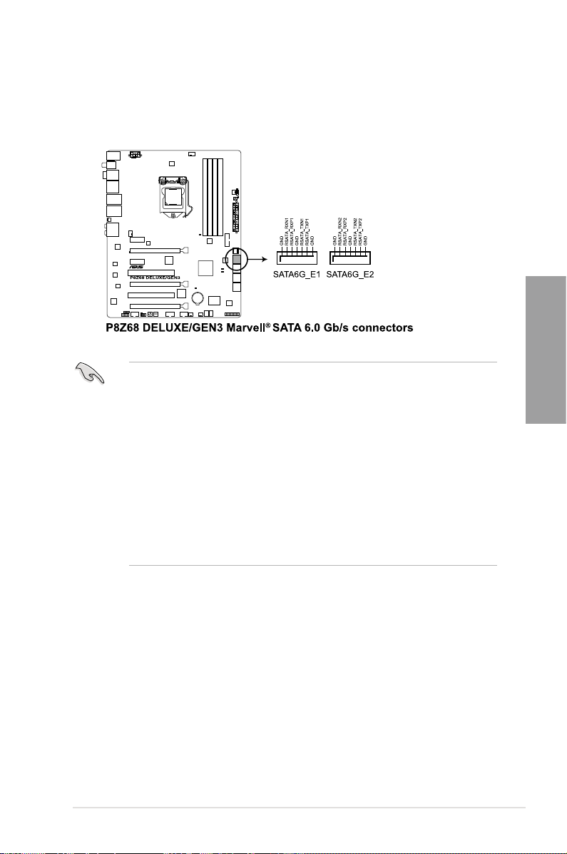
3. Marvell® Serial ATA 6.0 Gb/s connectors (7-pin SATA6G_E1/E2 [navy blue])
These connectors connect to Serial ATA 6.0 Gb/s hard disk drives via Serial ATA 6.0
Gb/s signal cables.
• The SATA6G_E1/E2 (navy blue) connectors are for data drives only. ATAPI device is
not supported.
•
You must install Windows® XP Service Pack 3 or later versions before using Serial ATA
hard disk drives.
•
When using NCQ, set the
Refer to section
• Press <Ctrl> + <M> during POST to enter the Marvell RAID utility to create or delete a
RAID conguration.
• If you want to install a Windows operating system to a RAID conguration created
using the Marvell SATA controller, you have to create a RAID driver disk using the
motherboard support DVD and load the driver during OS installation. For 32/64bit
Windows XP OS, load rst the
91xx SATA Controller Driver
Marvell 91xx SATA Controller Driver
Marvell Storage Controller
3.5.6 Onboard Devices Conguration
Marvell shared library
. For Windows Vista / Windows 7 OS, load only the
.
item in the BIOS to [Enabled].
for details.
driver, and then load
Marvell
Chapter 2
ASUS P8Z68 DELUXE/GEN3 2-27
Page 46

4. USB 3.0 connector (20-1 pin USB3_34)
This connector is for the additional USB 3.0 ports, and complies with the USB 3.0
specicaton that supports up to 480 MBps connection speed. If the USB 3.0 front panel
cable is available from your system chassis, with this USB 3.0 connector, you can have
a front panel USB 3.0 solution.
Chapter 2
5. USB 2.0 connectors (10-1 pin USB1112; USB1314)
These connectors are for USB 2.0 ports. Connect the USB module cable to any of
these connectors, then install the module to a slot opening at the back of the system
chassis. These USB connectors comply with USB 2.0 specication that supports up to
48 MBps connection speed.
You can connect the ASUS front panel USB 3.0 box to this connector to obtain the front
panel USB 3.0 solution.
Never connect a 1394 cable to the USB connectors. Doing so will damage the motherboard!
You can connect the front panel USB cable to the ASUS Q-Connector (USB, blue) rst, and
then install the Q-Connector (USB) to the USB connector onboard if your chassis supports
front panel USB ports.
The USB 2.0 module is purchased separately.
2-28 Chapter 2: Hardware information
Page 47

6. IEEE 1394a port connector (10-1 pin IE1394_2)
This connector is for an IEEE 1394a port. Connect the IEEE 1394a module cable
to this connector, then install the module to a slot opening at the back of the system
chassis.
Never connect a USB cable to the IEEE 1394a connector. Doing so will damage the
motherboard!
The IEEE 1394 bracket is purchased separately.
7. Digital audio connector (4-1 pin SPDIF_OUT)
This connector is for an additional Sony/Philips Digital Interface (S/PDIF) port(s).
Connect the S/PDIF Out module cable to this connector, then install the module to a
slot opening at the back of the system chassis.
Chapter 2
The S/PDIF module is purchased separately.
ASUS P8Z68 DELUXE/GEN3 2-29
Page 48

8. CPU, chassis, and power fan connectors
(4-pin CPU_FAN; 4-pin CHA_FAN1; 3-pin CHA_FAN2; 3-pin PWR_FAN1/2)
Connect the fan cables to the fan connectors on the motherboard, ensuring that the
black wire of each cable matches the ground pin of the connector.
Chapter 2
Do not forget to connect the fan cables to the fan connectors. Insufcient air ow inside the
system may damage the motherboard components. These are not jumpers! Do not place
jumper caps on the fan connectors!
• The CPU_FAN connector supports the CPU fan of maximum 1A (12 W) fan power.
• Only the CPU_FAN, CHA_FAN 1 and CHA_FAN 2 connectors support the ASUS FAN
Xpert feature.
• If you install two VGA cards, we recommend that you plug the rear chassis fan cable
to the motherboard connector labeled CHA_FAN1 or CHA_FAN2 for better thermal
environment.
2-30 Chapter 2: Hardware information
Page 49

9. Front panel audio connector (10-1 pin AAFP)
This connector is for a chassis-mounted front panel audio I/O module that supports
either HD Audio or legacy AC`97 audio standard. Connect one end of the front panel
audio I/O module cable to this connector.
• We recommend that you connect a high-denition front panel audio module to this
connector to avail of the motherboard’s high-denition audio capability.
• If you want to connect a high-denition front panel audio module to this connector, setIf you want to connect a high-denition front panel audio module to this connector, set
the
Front Panel Type
front panel audio module to this connector, set the item to
connector is set to
item in the BIOS setup to
.
[HD]
if you want to connect an AC'97
[HD];
. By default, this
[AC97]
10. ATX power connectors (24-pin EATXPWR; 8-pin EATX12V)
These connectors are for ATX power supply plugs. The power supply plugs are
designed to t these connectors in only one orientation. Find the proper orientation and
push down rmly until the connectors completely t.
Chapter 2
ASUS P8Z68 DELUXE/GEN3 2-31
Page 50

Chapter 2
• For a fully congured system, we recommend that you use a power supply unit
(PSU) that complies with ATX 12 V Specication 2.0 (or later version) and provides a
minimum power of 350 W.
• Do not forget to connect the 4-pin/8-pin EATX12 V power plug; otherwise, the system
will not boot.
• Use of a PSU with a higher power output is recommended when conguring a system
with more power-consuming devices. The system may become unstable or may not
boot up if the power is inadequate.
• If you want to use two or more high-end PCI Express x16 cards, use a PSU with
1000W power or above to ensure the system stability.
• If you are uncertain about the minimum power supply requirement for your system,
refer to the Recommended Power Supply Wattage Calculator at
com/PowerSupplyCalculator/PSCalculator.aspx?SLanguage=en-us
http://support.asus.
for details.
PSU Suggested List
AcBel PC7030 Gigabyte P610A-C1
AcBel API5PC36 GoldenField ATX-S398
AcBel PC6018 GoldenField ATX-S550
AMA AA1200U-C GreatWall BTX-600SE
AMA AA1000U-C HECHUAN ST-ATX330
Antec SG-850 Huntkey R85
Antec EA-380 Huntkey 磐石500
ASUS P-50GA I-cute AP-600S
ASUS P-55GA In-Win COMMANDER-IRP-COM1500
ASUS U-65GA OCZ 1000PXS
ASUS U-75HA OCZ 780MXS
Be quiet BN073 SAMA YUHUI-350P
Be quiet BN077 Seasonic SS-500GB
Be quiet P6-PRO-850W Seasonic SS-850EM
Bubalus PE600WJD Seasonic SS-900HP
CoolerMaster RS-650 Seventeam ST-420BKP
CoolerMaster RS-750 Seventeam ST-522HLP
CoolerMaster RS-850EMBA Seventeam ST550EAJ-05F
CoolerMaster RS-A00-ESBA SHARKOON SHA-R600M
CoolerMaster RS-C50-EMBA-D2 Silverstone SST-ST50EF
Coolive AP-350F Silverstone SST-ST85F
Corsair CMPSU-550VX Silverstone ST1000
Corsair CMPSU-620HX Snake PSH500V
Corsair CMPSU-750TX Snake PSH850V
CWT PSH650V-D Snake PMW-350WL
CWT PSH750V-D Tagan TG1100-U33
Delta GPS-550AB Tagan BZII1200
EnerMAX EPG600AWT Thermaltake W0133RU
EnerMAX EGX1000EWL Thermaltake W0133RE
EnerMAX EIN720AWT TOPower TOP-500P5
FSP ATX-300PNR Zalman ZM600-HP
Gigabyte M550A-D1 Zippy HP2-6500PE (G1)
2-32 Chapter 2: Hardware information
Page 51

11. System panel connector (20-8 pin PANEL)
This connector supports several chassis-mounted functions.
• System power LED (2-pin PLED)
This 2-pin connector is for the system power LED. Connect the chassis power LED
cable to this connector. The system power LED lights up when you turn on the system
power, and blinks when the system is in sleep mode.
• Hard disk drive activity LED (2-pin IDE_LED)
This 2-pin connector is for the HDD Activity LED. Connect the HDD Activity LED cable
to this connector. The IDE LED lights up or ashes when data is read from or written to
the HDD.
• System warning speaker (4-pin SPEAKER)
This 4-pin connector is for the chassis-mounted system warning speaker. The speaker
allows you to hear system beeps and warnings.
• ATX power button/soft-off button (2-pin PWRSW)
This connector is for the system power button. Pressing the power button turns the
system on or puts the system in sleep or soft-off mode depending on the BIOS settings.
Pressing the power switch for more than four seconds while the system is ON turns the
system OFF.
• Reset button (2-pin RESET)
This 2-pin connector is for the chassis-mounted reset button for system reboot without
turning off the system power.
Chapter 2
ASUS P8Z68 DELUXE/GEN3 2-33
Page 52

2.3 Building your computer system
2.3.1 Additional tools and components to build a PC system
1 bag of screws Philips (cross) screwdriver
Chapter 2
PC chassis Power supply unit
Intel LGA 1155 CPU Intel LGA 1155 compatible CPU Fan
DIMM SATA hard disk drive
SATA optical disc drive (optional) Graphics card (optional)
The tools and components in the table above are not included in the motherboard package.
2-34 Chapter 2: Hardware information
Page 53

A
B
2.3.2 CPU installation
The LGA1156 CPU is incompatible with the LGA1155 socket. DO NOT install a LGA1156
CPU on the LGA1155 socket.
1
2
Chapter 2
3
ASUS P8Z68 DELUXE/GEN3 2-35
Page 54

C
B
A
4
Chapter 2
5
6
2-36 Chapter 2: Hardware information
Page 55

2.3.3 CPU heatsink and fan assembly installation
Apply the Thermal Interface Material
to the CPU heatsink and CPU
before you install the heatsink and
fan if necessary.
To install the CPU heatsink and fan assembly
1
B
A
B
A
3 4
2
Chapter 2
ASUS P8Z68 DELUXE/GEN3 2-37
Page 56

To uninstall the CPU heatsink and fan assembly
1
Chapter 2
2
A
B
B
A
2-38 Chapter 2: Hardware information
Page 57

2.3.4 DIMM installation
1
2
3
Chapter 2
To remove a DIMM
B
A
ASUS P8Z68 DELUXE/GEN3 2-39
Page 58
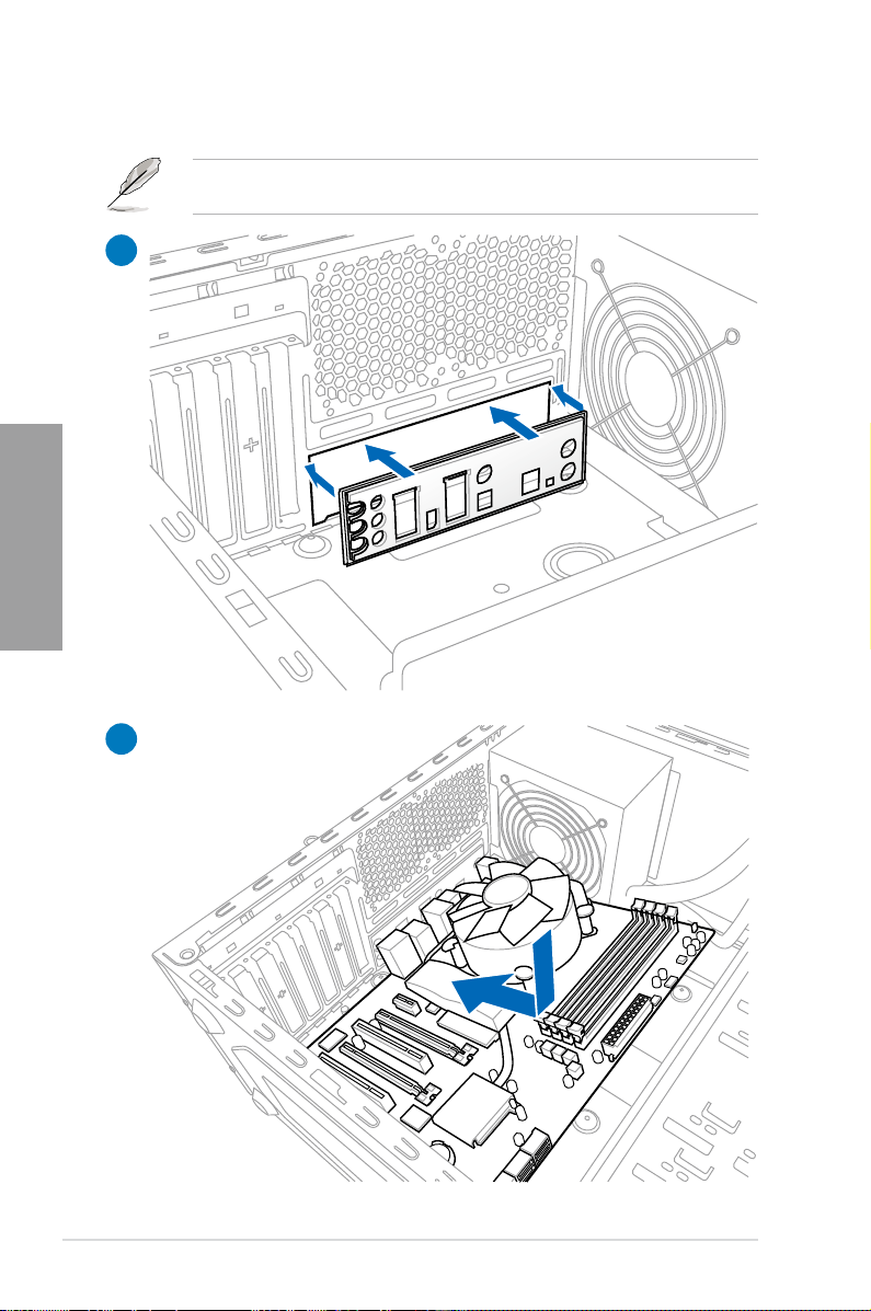
2.3.5 Motherboard installation
1
Chapter 2
2
The diagrams in this section are for reference only. The motherboard layout may vary with
models, but the installation steps remain the same.
2-40 Chapter 2: Hardware information
Page 59

3
Chapter 2
DO NOT overtighten the screws! Doing so can damage the motherboard.
ASUS P8Z68 DELUXE/GEN3 2-41
Page 60

2.3.6 ATX Power connection
1
Chapter 2
2
OR OR
2-42 Chapter 2: Hardware information
Page 61

2.3.7 SATA device connection
1
2
OR
OR
Chapter 2
ASUS P8Z68 DELUXE/GEN3 2-43
Page 62

2.3.8 Front I/O Connector
IDE_LED
POWER SW
RESET SW
IDE_LED-
IDE_LED+
PWR
Reset
Ground
Ground
To install ASUS Q-Connector
1 2
Chapter 2
To install USB 2.0 Connector To install front panel audio connector
AAFP
USB 2.0
To install USB 3.0 Connector
USB 3.0
2-44 Chapter 2: Hardware information
Page 63

2.3.9 Expension Card installation
To install PCIe x16 cards
To install PCIe x1 cards To install PCI cards
Chapter 2
ASUS P8Z68 DELUXE/GEN3 2-45
Page 64

2.3.10 Rear panel connection
Chapter 2
Rear panel connectors
1. PS/2 keyboard/mouse combo port 9. Optical S/PDIF Out port
2. Coaxial S/PDIF Out port 10. External SATA port
3. USB 2.0 ports 5 and 6 11. Power External SATA port
4. Bluetooth module* 12. IEEE 1394a port
5. USB 2.0 ports 3 and 4 13. USB 2.0 ports 1 and 2
6. Realtek® LAN (RJ-45) port** 14. USB 3.0 ports 1 and 2
7. Intel® LAN (RJ-45) port**
(Recommended for single LAN usage)
8. USB 2.0 ports 9 and 10 16. Audio I/O ports***
*, ** and ***: Refer to the tables on the next page for bluetooth module LED, LAN port LED, and
audio port denitions.
2-46 Chapter 2: Hardware information
15. Clear CMOS switch
Page 65

• Press the Clear CMOS switch to clear BIOS setup information only when the system
hangs due to overclocking.
• DO NOT insert a different connector to the external SATA port.
• Due to USB 3.0 controller limitation, USB 3.0 devices can only be used under
Windows® OS environment and after the USB 3.0 driver installation.
• USB 3.0 devices can only be used as data storage only.
• We strongly recommend that you connect USB 3.0 devices to USB 3.0 ports for faster
and better performance for your USB 3.0 devices.
• If you want to use the hot-plug function of the external SATA ports, you have to set the
JMB Storage Controller
JMB36X Controller Driver
Onboard Devices Conguration
item in the BIOS setting to [Enabled] and install the
from the motherboard support DVD. Refer to section
for details.
* Bluetooth module LED indications
Status Description
Off No link
Blue Linked
Blinking Data activity
** LAN ports LED indications
Activity Link LED Speed LED
Status Description Status Description
OFF No link OFF 10 Mbps connection
ORANGE Linked ORANGE 100 Mbps connection
BLINKING Data activity GREEN 1 Gbps connection
ACT/LINK
LED
LAN port
JMicron
3.5.6
Chapter 2
SPEED
LED
*** Audio 2, 4, 6, or 8-channel conguration
Port Headset
2-channel
Light Blue Line In Line In Line In Line In
Lime Line Out Front Speaker Out Front Speaker Out Front Speaker Out
Pink Mic In Mic In Mic In Mic In
Orange – – Center/Subwoofer Center/Subwoofer
Black – Rear Speaker Out Rear Speaker Out Rear Speaker Out
Gray – – – Side Speaker Out
ASUS P8Z68 DELUXE/GEN3 2-47
4-channel 6-channel 8-channel
Page 66

2.3.11 Audio I/O connections
Audio I/O ports
Connect to Headphone and Mic
Chapter 2
Connect to Stereo Speakers
Connect to 2.1 channel Speakers
2-48 Chapter 2: Hardware information
Page 67

Connect to 4.1 channel Speakers
Connect to 5.1 channel Speakers
Chapter 2
Connect to 7.1 channel Speakers
When the DTS Surround Sensation UltraPC function is enabled, ensure to connect the rear
speaker to the gray port.
ASUS P8Z68 DELUXE/GEN3 2-49
Page 68

2.4 Starting up for the rst time
1. After making all the connections, replace the system case cover.
2. Be sure that all switches are off.
3. Connect the power cord to the power connector at the back of the system chassis.
4. Connect the power cord to a power outlet that is equipped with a surge protector.
5. Turn on the devices in the following order:
a. Monitor
b. External SCSI devices (starting with the last device on the chain)
c. System power
6. After applying power, the system power LED on the system front panel case lights up.
For systems with ATX power supplies, the system LED lights up when you press the
ATX power button. If your monitor complies with the “green” standards or if it has a
“power standby” feature, the monitor LED may light up or change from orange to green
Chapter 2
after the system LED turns on.
The system then runs the power-on self tests or POST. While the tests are running, the
BIOS beeps (refer to the BIOS beep codes table below) or additional messages appear
on the screen. If you do not see anything within 30 seconds from the time you turned
on the power, the system may have failed a power-on test. Check the jumper settings
and connections or call your retailer for assistance.
BIOS Beep Description
One short beep VGA detected
One continuous beep followed by two
short beeps then a pause (repeated)
One continuous beep followed by three
short beeps
One continuous beep followed by four
short beeps
Quick boot set to disabled
No keyboard detected
No memory detected
No VGA detected
Hardware component failure
7. At power on, hold down the <Delete> key to enter the BIOS Setup. Follow the
instructions in Chapter 3.
2.5 Turning off the computer
While the system is ON, pressing the power switch for less than four seconds puts the system
on sleep mode or soft-off mode, depending on the BIOS setting. Pressing the power switch
for more than four seconds lets the system enter the soft-off mode regardless of the BIOS
setting.
2-50 Chapter 2: Hardware information
Page 69

Chapter 3
Chapter 3: BIOS setup
3.1 Knowing BIOS
The ASUS UEFI BIOS offers a user-friendly interface that goes beyond traditional
keyboard-only BIOS controls to enable more exible and convenient mouse input. Users
can easily navigate the UEFI BIOS with the same smoothness as their operating system.
The term “BIOS” in this user manual refers to “UEFI BIOS” unless otherwise specied.
BIOS (Basic Input and Output System) stores system hardware settings such as storage
device conguration, overclocking settings, advanced power management, and boot device
conguration that are needed for system startup in the motherboard CMOS. In normal
circumstances, the default BIOS settings apply to most conditions to ensure optimum
performance. We recommend that you not change the default BIOS settings except in
the following circumstances:
• An error message appears on the screen during the system bootup and requests you to
run the BIOS Setup.
• You have installed a new system component that requires further BIOS settings or
update.
Inappropriate settings of the BIOS may result to instability or failure to boot. We strongly
recommend that you change the BIOS settings only with the help of a trained service
personnel.
3.2 BIOS setup program
A BIOS setup program is provided for BIOS item modication. When you start up the
computer, the system provides you with the opportunity to run this program. Press <Del>
during the Power-On Self-Test (POST) to enter the Setup utility. Otherwise, POST continues
with its test routines.
If you wish to enter Setup after POST, press <Ctrl> + <Alt> + <Delete>, or press the reset
button on the system chassis to restart the system. You can also turn the system off and then
turn it back on to restart the system. Do this last option only if the rst two failed.
• The BIOS setup screens shown in this section are for reference purposes only, and
may not exactly match what you see on your screen.
• Ensure that a USB mouse is connected to your motherboard if you want to use the
mouse to control the BIOS setup program.
• If the system becomes unstable after changing any BIOS setting, load the default
settings to ensure system compatibility and stability. Select the Load Optimized
Defaults item under the Exit menu. See section 3.9 Exit Menu for details.
• If the system fails to boot after changing any BIOS setting, try to clear the CMOS and
reset the motherboard to the default value. See sectionSee section 2.2.8 Jumper for information
on how to erase the RTC RAM.
• The BIOS setup program does not support the bluetooth devices.
The BIOS setup program is designed to make it as easy to use as possible. Being a
menu-driven program, it lets you scroll through the various submenus and select from the
available options using a keyboard or a USB mouse.
The BIOS setup program can be used under two modes: EZ Mode and Advanced Mode.
You can change modes from the Exit menu or from the Exit/Advanced Mode button in the
EZ Mode/Advanced Mode screen.
ASUS P8Z68 DELUXE/GEN3 3-1
Chapter 3
Page 70

3.2.1 EZ Mode
By default, the EZ Mode screen appears when you enter the BIOS setup program. The EZ
Mode provides you an overview of the basic system information, and allows you to select
the display language, system performance mode and boot device priority. To access the
Advanced Mode, click Exit/Advanced Mode, then select Advanced Mode.
The default screen for entering the BIOS setup program can be changed. Refer to the
Setup Mode item in sectionsection 3.7 Boot memu for details.
Displays the CPU/motherboard temperature,
CPU/5V/3.3V/12V voltage output,
CPU/chassis/power fan speed
Monday [9/13/2010]
Temperature Voltage Fan Speed
CPU +113.0ºF/+45.0ºC CPU 1.248V 5V 5.160V CPU_FAN 3325RPM PWR_FAN1 N/A
MB +75.2ºF/+40.0ºC 3.3V 3.344V 12V 12.248V CHA_FAN1 N/A CHA_FAN2 N/A
System Performance
Chapter 3
Performance Energy Saving
Boot Priority
Use the mouse to drag or keyboard to navigate to decide the boot priority.
Selects the boot device priority
Displays the system properties of the
selected mode on the right hand side
EFI BIOS Utility - EZ Mode
P8Z68 DELUXE/GEN3
BIOS Version : 0209 Build Date : 03/04/2011
CPU Type : Genuine Intel(R) CPU 0 @ 3.10GHz Speed : 3531 MHz
Total Memory : 512 MB (DDR3 1066MHz)
Quiet
Selects the display language of
the BIOS setup program
Exits the BIOS setup program without saving
the changes, saves the changes and resets
the system, or enters the Advanced Mode
Normal
Power Saving mode
Normal mode ASUS Optimal mode
Selects the boot device priority
Clicks to display all fan
speeds if available
Exit/Advanced Mode
Boot Menu(F8)
Loads optimized default
English
Default(F5)
• The boot device options vary depending on the devices you installed to the system.
• The Boot Menu(F8) button is available only when the boot device is installed to the
system.
3-2 Chapter 3: BIOS setup
Page 71

3.2.2 Advanced Mode
The Advanced Mode provides advanced options for experienced end-users to congure
the BIOS settings. The gure below shows an example of the Advanced Mode. Refer to the
following sections for the detailed congurations.
To access the Advanced Mode, click Exit, then select Advanced Mode.
Back button
Menu items
EFI BIOS Utility - Advanced Mode
Main
Back Advanced\ Onboard Devices Conguration >
HD Audio Controller Enabled
Front Panel Type HD
SPDIF Out Type SPDIF
Renesas USB 3.0 Controller Enabled
Bluetooth Controller Enabled
VIA 1394 Controller Enabled
PCI Express X16_3 slot (black) bandwidth Auto
PCI Express X1_1 slot or USB3.0 switch X1 Slot
Marvell Storage Controller AHCI Mode
Marvell Storage OPROM Enabled
Ai Tweaker
Submenu item
Menu bar
Bluetooth Controller
Disabled
Enabled
Version 2.00.1201. Copyright (C) 2010 American Megatrends, Inc.
Pop-up window
Conguration elds
Advanced Monitor Boot Tool
Scroll bar
General help
Enabled/Disabled Bluetooth Controller
→←: Select Screen
↑↓: Select Item
Enter: Select
+/-: Change Opt.
F1: General Help
F2: Previous Values
F5: Optimized Defaults
F10: Save ESC: Exit
F12: Print Screen
Navigation keys
Exit
Menu bar
The menu bar on top of the screen has the following main items:
Main For changing the basic system conguration
Ai Tweaker For changing the overclocking settings
Advanced For changing the advanced system settings
Monitor For displaying the system temperature, power status, and changing the fan settings.
Boot For changing the system boot conguration
Tool For conguring options for special functions
Exit For selecting the exit options and loading default settings
Chapter 3
ASUS P8Z68 DELUXE/GEN3 3-3
Page 72

Menu items
The highlighted item on the menu bar displays the specic items for that menu. For example,
selecting Main shows the Main menu items.
The other items (Ai Tweaker, Advanced, Monitor, Boot, Tool, and Exit) on the menu bar have
their respective menu items.
Back button
This button appears when entering a submenu. Press <Esc> or use the USB mouse to click
this button to return to the previous menu screen.
Submenu items
A greater than sign (>) before each item on any menu screen means that the item has a
submenu. To display the submenu, select the item and press <Enter>.
Pop-up window
Select a menu item and press <Enter> to display a pop-up window with the conguration
options for that item.
Scroll bar
A scroll bar appears on the right side of a menu screen when there are items that do not t on
the screen. Press the Up/Down arrow keys or <Page Up> / <Page Down> keys to display the
other items on the screen.
Navigation keys
At the bottom right corner of the menu screen are the navigation keys for the BIOS setup
Chapter 3
program. Use the navigation keys to select items in the menu and change the settings.
General help
At the top right corner of the menu screen is a brief description of the selected item. UseUse
<F12> key to capture the BIOS screen and save it to the removable storage device.
Conguration elds
These elds show the values for the menu items. If an item is user-congurable, you can
change the value of the eld opposite the item. You cannot select an item that is not
user-congurable.
A congurable eld is highlighted when selected. To change the value of a eld, select it and
press <Enter> to display a list of options.
3-4 Chapter 3: BIOS setup
Page 73

3.3 Main menu
The Main menu screen appears when you enter the Advanced Mode of the BIOS Setup
program. The Main menu provides you an overview of the basic system information, and
allows you to set the system date, time, language, and security settings.
EFI BIOS Utility - Advanced Mode
Main
BIOS Information
BIOS Version 0202 x64
Build Date 04/25/2011
EC Version MBECE-0020
ME Version 7.1.10.1065
South Bridge Stepping B3 Stepping
CPU Information
Intel(R) Core(TM) CPU 0 @ 3.10GHz
Speed 3100 MHz
Memory Information
Total Memory 512 MB
Speed 1097 MHz
System Language English
System Date [Fri 03/25/2011]
System Time [16:46:15]
Access Level Administrator
> Security
Ai Tweaker
Advanced Monitor Boot Tool
Choose the system default language
Security
The Security menu items allow you to change the system security settings.
EFI BIOS Utility - Advanced Mode
Main
Back Main\ Security >
Password Description
If ONLY the Administrator's password is set,
then this only limits access to Setup and is
only asked for when entering Setup
If ONLY the User's password is set, then this
is a power on password and must be entered to
boot or enter Setup. In Setup the User will
have Administrator rights
Administrator Password Not Installed
User Password Not Installed
Administrator Password
User Password
Ai Tweaker
Advanced Monitor Boot Tool
To clear the administrator password,
key in the current password in the
Enter Current Password box,
and then press <Enter> when
prompted to create/conrm the
password.
Exit
Exit
Chapter 3
• If you have forgotten your BIOS password, erase the CMOS Real Time Clock (RTC)
RAM to clear the BIOS password. See section 2.3.7 Jumper for information on how to
erase the RTC RAM.
• The Administrator or User Password items on top of the screen show the default
Not Installed. After you set a password, these items show Installed.
ASUS P8Z68 DELUXE/GEN3 3-5
Page 74

Administrator Password
If you have set an administrator password, we recommend that you enter the administrator
password for accessing the system. Otherwise, you might be able to see or change only
selected elds in the BIOS setup program.
To set an administrator password:
1. Select the Administrator Password item and press <Enter>.
2. From the Create New Password box, key in a password, then press <Enter>.
3. Conrm the password when prompted.
To change an administrator password:
1. Select the Administrator Password item and press <Enter>.
2. From the Enter Current Password box, key in the current password, then press
<Enter>.
3. From the Create New Password box, key in a new password, then press <Enter>.
4. Conrm the password when prompted.
To clear the administrator password, follow the same steps as in changing an administrator
password, but press <Enter> when prompted to create/conrm the password. After you clear
the password, the Administrator Password item on top of the screen shows Not Installed.
User Password
If you have set a user password, you must enter the user password for accessing the system.
The User Password item on top of the screen shows the default Not Installed. After you set
a password, this item shows Installed.
Chapter 3
To set a user password:
1. Select the User Password item and press <Enter>.
2. From the Create New Password box, key in a password, then press <Enter>.
3. Conrm the password when prompted.
To change a user password:
1. Select the User Password item and press <Enter>.
2. From the Enter Current Password box, key in the current password, then press
<Enter>.
3. From the Create New Password box, key in a new password, then press <Enter>.
4. Conrm the password when prompted.
To clear the user password, follow the same steps as in changing a user password, but press
<Enter> when prompted to create/conrm the password. After you clear the password, the
User Password item on top of the screen shows Not Installed.
3-6 Chapter 3: BIOS setup
Page 75

3.4 Ai Tweaker menu
The Ai Tweaker menu items allow you to congure overclocking-related items.
Be cautious when changing the settings of the Ai Tweaker menu items. Incorrect eld
values can cause the system to malfunction.
The conguration options for this section vary depending on the CPU and DIMM model you
installed on the motherboard.
EFI BIOS Utility - Advanced Mode
Main
Target CPU Turbo-Mode Speed : 4429MHz
Target DRAM Speed : 1097MHz
Ai Overclock Tuner Auto
BCLK/PCIE Frequency 103.0
Turbo Ratio Auto
By All Cores (Can Adjust in OS) 43
Internal PLL Overvoltage Auto
Memory Frequency Auto
iGPU Max. Frequency Auto
EPU Power Saving Mode Disabled
> OC Tuner
> DRAM Timing Control
> CPU Power Management
Ai Tweaker
Version 2.00.1201. Copyright (C) 2010 American Megatrends, Inc.
Advanced Monitor Boot Tool
Scroll down to display the following items:
CPU Voltage 1.176V Offset Mode
Offset Mode Sign +
CPU Offset Voltage Auto
iGPU Offset Mode Sign +
iGPU Offset Voltage Auto
DRAM Voltage 1.515V Auto
VCCIO Voltage 1.062V Auto
CPU PLL Voltage 1.800V Auto
PCH Voltage 1.062V Auto
DRAM DATA REF Voltage on CHA Auto
DRAM CTRL REF Voltage on CHA Auto
DRAM DATA REF Voltage on CHB Auto
DRAM CTRL REF Voltage on CHB Auto
CPU Spread Spectrum Auto
Version 2.00.1201. Copyright (C) 2010 American Megatrends, Inc.
[X.M.P.] When XMP is enabled BLCK
frequency, CPU ratio and memory
parameters will be auto optimized.
→←: Select Screen
↑↓: Select Item
Enter: Select
+/-: Change Opt.
F1: General Help
F2: Previous Values
F5: Optimized Defaults
F10: Save ESC: Exit
F12: Print Screen
Exit
Chapter 3
ASUS P8Z68 DELUXE/GEN3 3-7
Page 76

Ai Overclock Tuner [Auto]
Allows you to select the CPU overclocking options to achieve the desired CPU internal
frequency. Select any of these preset overclocking conguration options:
[Auto] Loads the optimal settings for the system.
[Manual] Allows you to individually set overclocking parameters.
[X.M.P.] If you install memory modules supporting the eXtreme Memory Prole
BCLK/PCIE Frequency [XXX]
Allows you to adjust the CPU and VGA frequency to enhance the system performance. Use
the <+> and <-> keys to adjust the value. You can also key in the desired value using the
numeric keypad. The values range from 80.0MHz to 300.0MHz.
eXtreme Memory Prole [High Performance]
This item appears only when you set the Ai Overclock Tuner item to [X.M.P.] and allows you
to select the X.M.P. mode supported by your memory module.
Conguration options: [Disabled] [Prole #1] [Prole #2]
Turbo Ratio [By All Cores]
Allows you to manually adjust the Trubo CPU ratio.
[Auto] All Turbo ratio are set by Intel CPU default settings.
[By ALL Cores (Can Adjust in OS)] All numbers of active cores will be set to one single
Chapter 3
[By Per Core (Cannot Adjust in OS)] All numbers of active cores can be set to an individual
(X.M.P.) Technology, choose this item to set the proles supported by your
memory modules for optimizing the system performance.
Turbo ratio in OS.
Turbo ratio in BIOS.
By ALL Cores (Can Adjust in OS) [XX]
This item appears only when you set the Turbo Ratio item to [By ALL Cores (Can Adjust in
OS)]. Use the <+> and <-> keys to adjust the value.
1-/2-/3-/4-Core Ratio Limit [XX]
This item appears only when you set the Turbo Ratio item to [By Per Core (Cannot Adjust in
OS)]. Use the <+> and <-> keys to adjust the value.
Internal PLL Overvoltage [Auto]
Allows you to set the Internal PLL Overvoltage.
Conguration options: [Auto] [Enabled] [Disabled]
Memory Frequency [Auto]
Allows you to set the memory operating frequency. The conguration options vary with the
BCLK/PCIE Frequency item settings.
Selecting a very high memory frequency may cause the system to become unstable! If this
happens, revert to the default setting.
3-8 Chapter 3: BIOS setup
Page 77

The following items appears only when you set the Initiate iGPU items to [Enabled].
iGPU Max. Frequency [XXXX]
Use the <+> and <-> keys to adjust the value. The values range from 1100MHz to 3000MHz
with a 50MHz interval.
EPU Power Saving MODE [Disabled]
Allows you to enable or disable the EPU power saving function.
Conguration options: [Disabled] [Enabled]
EPU Setting [Auto]
This item appears only when you set the EPU Power Saving MODE item to [Enabled.] and
allows you to select the EPU power saving mode.
Conguration options: [Auto] [Light Power Saving Mode] [Medium Power Saving Mode] [Max
Power Saving Mode]
OC Tuner
OC Tuner automatically overclocks the frequency and voltage of CPU and DRAM for
enhancing the system performance. Conguration options: [OK] [Cancel]
DRAM Timing Control
The sub-items in this menu allow you to set the DRAM timing control features. Use the <+>
and <-> keys to adjust the value. To restore the default setting, type [auto] using the keyboard
and press the <Enter> key.
Changing the values in this menu may cause the system to become unstable! If this
happens, revert to the default settings.
CPU Power Management
The sub-items in this menu allow you to set the CPU ratio and features.
CPU Ratio [Auto]
Allows you to manually adjust the maximum non-turbo CPU ratio. Use <+> and <-> keys to
adjust the value. The valid value ranges vary according to your CPU model.
Enhanced Intel SpeedStep Technology [Enabled]
Allows you to enable or disable the Enhanced Intel® SpeedStep Technology (EIST).
[Disabled] Disables this function.
[Enabled] The operating system dynamically adjusts the processor voltage and
core frequency which may result in decreased average consumption and
decreased average heat production.
ASUS P8Z68 DELUXE/GEN3 3-9
Chapter 3
Page 78

Turbo Mode [Enabled]
This item appears only when you set the EIST item to [Enabled].
[Enabled] Allows processor cores to run faster than marked frequency in specic
[Disabled] Disables this function.
Long Duration Power Limit [Auto]
Use the <+> and <-> keys to adjust the value.
Long Duration Maintained [Auto]
Use the <+> and <-> keys to adjust the value.
Short Duration Power Limit [Auto]
Use the <+> and <-> keys to adjust the value.
Additional Turbo Voltage [Auto]
Use the <+> and <-> keys to adjust the value.
Primary Plane Current Limit [Auto]
Maximum instaneous current allowed at any given time for CPU cores.
Use <+> and <-> key to adjust the value at 0.125A increment.
DIGI+ VRM
Load-Line Calibration [Auto]
Chapter 3
Load-line is dened by Intel VRM spec and affects CPU voltage. The CPU working voltage
will decrease proportionally to CPU loading. Higher load-line calibration would get higher
voltage and better overclocking performance, but increase the CPU and VRM thermal. This
item allows you to adjust the voltage range from the following percentages to boost the
system performance: 0% (Regular), 25% (Medium), 50% (High), 75% (Ultra High) and 100%
(Extreme).
Conguration options: [Auto] [Regular] [Medium] [High] [Ultra High] [Extreme]
condition.
The following ve items appear only when you set the EIST and Turbo Mode items to
[Enabled].
The actual performance boost may vary depending on your CPU speciation.
VRM Frequency [Auto]
Switching frequency will affect the VRM transient response and component thermal. Setting a
higher frequency gets faster transient response.
[Auto] Allows you to enable or disable the Spread Spectrum item.
[Manual] Allows you to manually set the frequency with a 10k Hz interval.
VRM Spread Spectrum [Disabled]
This item appears only when you set the Frequency item to [Auto] and allows you to enable
the spread spectrum to enhance system stability.
3-10 Chapter 3: BIOS setup
Page 79

VRM Fixed Frequency Mode [XXX]
This item appears only when you set the VRM Frequency item to [Manual] and allows you to
set a xed VRM frequency. Use the <+> and <-> keys to adjust the value. The values range
from 300k Hz to 500k Hz with a 10k Hz interval.
Phase Control [Extreme]
Phase number is the number of woorking VRM phase. Increasing phase number under
heavy system loading to get more transient and better thermal performance. Reducing phase
number under light system loading to increase VRM efciency
[Standard] Proceeds phase control depending on the CPU loading.
[Optimized] Loads the ASUS optimized phase tuning prole.
[Extreme] Proceeds the full phase mode.
[Manual Adjustment] Allows manual adjustment.
Manual Adjustment [Medium]
This item appears only when you set the Phase Control item to [Manual Adjustment].
Conguration options: [Ultra Fast] [Fast] [Medium] [Regular]
Duty Control [T.Probe]
[T.Probe] Maintains the VRM thermal balance.
[Extreme] Maintains the VRM current balance.
CPU Current Capability [100%]
This item provides wider total power range for overclocking. A higher value brings a wider
total power range and extends the overclocking frequency range simultaneously.
Conguration options: [100%] [110%] [120%] [130%] [140%]
The following items appears only when you set the Initiate iGPU items to [Enabled].
iGPU Load-line Calibration [Auto]
Allows you to set the iGPU Load-line Calibration.
Conguration options: [Auto] [Regular] [High] [Extreme]
iGPU Current Capability [100%]
Allows you to set the iGPU Current Capability.
Conguration options: [100%] [140%]
Do not remove the thermal module while changing the DIGI+ VRM related parrameters .
The thermal conditions should be monitored.
Some of the following items are adjusted by typing the desired values using the numeric
keypad and press the <Enter> key. You can also use the <+> and <-> keys to adjust the
value. To restore the default setting, type [auto] using the keyboard and press the <Enter>
key.
ASUS P8Z68 DELUXE/GEN3 3-11
Chapter 3
Page 80

CPU Voltage [Offset Mode]
[Manual Mode] Allows you to set a xed CPU voltage.
[Offset Mode] Allows you to set the Offset voltage.
Offset Mode Sign [+]
This item appears only when you set the CPU Voltage item to [Offset Mode].
[+] To offset the voltage by a positive value.
[–] To offset the voltage by a negative value.
CPU Offset Voltage [Auto]
This item appears only when you set the CPU Voltage item to [Offset Mode] and
allows you to set the Offset voltage. The values range from 0.005V to 0.635V with a
0.005V interval.
CPU Manual Voltage [Auto]
This item appears only when you set the CPU Voltage item to [Manual Mode] and
allows you to set a xed CPU voltage. The values range from 0.800V to 1.990V with a
0.005V interval.
iGPU Offset Mode Sign [+]
[+] To offset the voltage by a positive value.
Chapter 3
[–] To offset the voltage by a negative value.
iGPU Offset Voltage [Auto]
Allows you to set the iGPU Offset voltage. The values range from 0.005V to 0.635V
with a 0.005V interval.
Refer to the CPU documentation before setting the CPU voltage. Setting a high voltage
may damage the CPU permanently, and setting a low voltage may make the system
unstable.
The following items appears only when you set the Initiate iGPU items to [Enabled].
DRAM Voltage [Auto]
Allows you to set the DRAM voltage. The values range from 1.20V to 2.20V with a 0.00625V
interval.
According to Intel CPU spec, DIMMs with voltage requirement over 1.65V may damage
the CPU permanently. We recommend you install the DIMMs with the voltage requirement
below 1.65V.
VCCIO Voltage [Auto]
Allows you to set the VCCIO voltage. The values range from 0.80V to 1.70V with a 0.00625V
interval.
CPU PLL Voltage [Auto]
Allows you to set the CPU and PCH PLL voltage. The values range from 1.20V to 2.20V with
a 0.00625V interval.
3-12 Chapter 3: BIOS setup
Page 81

PCH Voltage [Auto]
Allows you to set the Platform Controller Hub volage. The values range from 0.80V to 1.70V
with a 0.01V interval.
• The values of the CPU Manual Voltage, CPU Offset Voltage, DRAM Voltage, VCCIO
Voltage, and PCH Voltage items are labeled in different color, indicating the risk levels
of high voltage settings.
• The system may need better cooling system to work stably under high voltage
settings.
Black Yellow Pink Red
CPU Manual Voltage 0.8V–1.22V 1.225V–1.280V 1.285V–1.335V 1.340V–1.990V
CPU Offset Voltage 0.005V–0.060V 0.065V–0.120V 0.125V–0.175V 0.180V–0.635V
iGPU Offset Voltage
DRAM Voltage
VCCIO Voltage
CPU PLL Voltage
PCH Voltage
0.005V–0.035V 0.04V–0.065V 0.07V–0.1V 0.105V–0.635V
1.20000V–
1.57500V
0.80000V–
1.10000V
1.20000V–
1.88750V
0.80000V–
1.10000V
1.58125V–
1.65000V
1.10625V–
1.15000V
1.89375V–
1.97500V
1.11000V–
1.15000V
1.65625V–
1.72500V
1.15625V–
1.20625V
1.98125V–
2.06875V
1.16000V–
1.20000V
1.73125V–
2.20000V
1.21250V–
1.70000V
2.07500V–
2.20000V
1.21000V–
1.70000V
DRAM DATA REF Voltage on CHA/B [Auto]
Allows you to set the DRAM DATA Reference Voltage on Channel A/B. The values
range from 0.395x to 0.630x with a 0.005x interval. Different ratio might enhance DRAM
overclocking ability.
DRAM CTRL REF Voltage on CHA/B [Auto]
Allows you to set the DRAM Control Reference Voltage on Channel A/B. The values
range from 0.395x to 0.630x with a 0.005x interval. Different ratio might enhance DRAM
overclocking ability.
CPU Spread Spectrum [Auto]
[Auto] Automatic conguration.
[Disabled] Enhances the BCLK overclocking ability.
[Enabled] Sets to [Enabled] for EMI control.
ASUS P8Z68 DELUXE/GEN3 3-13
Chapter 3
Page 82

3.5 Advanced menu
The Advanced menu items allow you to change the settings for the CPU and other system
devices.
Be cautious when changing the settings of the Advanced menu items. Incorrect eld values
can cause the system to malfunction.
> CPU Conguration
> System Agent Conguration
> PCH Conguration
> SATA Conguration
> USB Conguration
> Onboard Devices Conguration
> APM
Chapter 3
EFI BIOS Utility - Advanced Mode
Main
Ai Tweaker
Version 2.00.1201. Copyright (C) 2010 American Megatrends, Inc.
Advanced Monitor Boot Tool
CPU Conguration Parameters
→←: Select Screen
↑↓: Select Item
Enter: Select
+/-: Change Opt.
F1: General Help
F2: Previous Values
F5: Optimized Defaults
F10: Save ESC: Exit
F12: Print Screen
Exit
3-14 Chapter 3: BIOS setup
Page 83

3.5.1 CPU Conguration
The items in this menu show the CPU-related information that the BIOS automatically
detects.
The items shown in this screen may be different due to the CPU you installed.
EFI BIOS Utility - Advanced Mode
Main
Back Advanced\ CPU Conguration >
CPU Conguration
Intel(R) CPU 0 @ 3.10GHz
EM64T Supported
Processor Speed 3517 MHz
Processor Stepping 206a7
Microcode Revision 14
L1 Cache 256 KB
L2 Cache 1024 KB
L3 Cache 8192 KB
Processor Cores 4
Intel HT Technology Supported
CPU Ratio Range 16-34
CPU Current Ratio 34
CPU Ratio Auto
Intel Adaptive Thermal Monitor Enabled
Hyper-threading Enabled
Active Processor Cores All
Limit CPUID Maximum Disabled
Execute Disable Bit Enabled
Ai Tweaker
Version 2.00.1201. Copyright (C) 2010 American Megatrends, Inc.
Advanced Monitor Boot Tool
Scroll down to display the following items:
Intel Virtualization Technology Disabled
Enhanced Intel SpeedStep Technology Enabled
Turbo Mode Enabled
CPU C1E Auto
CPU C3 Report Auto
CPU C6 Report Auto
Version 2.00.1201. Copyright (C) 2010 American Megatrends, Inc.
Adjust Non-Turbo Ratio
→←: Select Screen
↑↓: Select Item
Enter: Select
+/-: Change Opt.
F1: General Help
F2: Previous Values
F5: Optimized Defaults
F10: Save ESC: Exit
F12: Print Screen
Exit
Chapter 3
CPU Ratio [Auto]
Allows you to set the ratio between the CPU Core Clock and the BCLK Frequency. Use <+>
and <-> keys to adjust the ratio. The valid value ranges vary according to your CPU model.
Intel Adaptive Thermal Monitor [Enabled]
[Enabled] Enables the overheated CPU to throttle its clock speed to cool down.
[Disabled] Disables the CPU thermal monitor function.
ASUS P8Z68 DELUXE/GEN3 3-15
Page 84

Hyper-threading [Enabled]
The Intel Hyper-Threading Technology allows a hyper-threading processor to appear as two
logical processors to the operating system, allowing the operating system to schedule two
threads or processes simultaneously.
[Enabled] Two threads per activated core are enabled.
[Disabled] Only one thread per activated core is enabled.
Active Processor Cores [All]
Allows you to choose the number of CPU cores to activate in each processor package.
Conguration options: [All] [1] [2] [3]
Limit CPUID Maximum [Disabled]
[Enabled] Allows legacy operating systems to boot even without support for CPUs
[Disabled] Disables this function.
Execute Disable Bit [Enabled]
[Enabled] Enables the No-Execution Page Protection Technology.
[Disabled] Forces the XD feature ag to always return to zero (0).
Intel(R) Virtualization Tech [Disabled]
[Enabled] Allows a hardware platform to run multiple operating systems separately
[Disabled] Disables this function.
Enhanced Intel SpeedStep Technology [Enabled]
Chapter 3
Allows you to enable or disable the Enhanced Intel® SpeedStep Technology (EIST).
[Disabled] The CPU runs at its default speed.
[Enabled] The operating system controls the CPU speed.
Turbo Mode [Enabled]
This item appears only when you set the EIST item to [Enabled] and allows you to enable or
disable the Intel® Turbo Mode Technology.
[Enabled] Allows processor cores to run faster than marked frequency in specic
[Disabled] Disables this function.
CPU C1E [Auto]
[Enabled] Enables the C1E support function. This item should be enabled in order to
[Disabled] Disables this function.
CPU C3 Report [Auto]
Allows you to disable or enable the CPU C3 report to OS.
CPU C6 Report [Auto]
Allows you to disable or enable the CPU C6 report to OS.
with extended CPUID functions.
and simultaneously, enabling one system to virtually function as several
systems.
condition.
enable the Enhanced Halt State.
3-16 Chapter 3: BIOS setup
Page 85

3.5.2 System Agent Conguration
EFI BIOS Utility - Advanced Mode
Exit
Main
Back Advanced\ System Agent Conguration >
System Agent Conguration
Initate Graphic Adapter PCIE/PCI
iGPU Memory 64M
Render Standy Enabled
Set this item to [Enabled] to enable Lucid Virtu/ NVIDIA Optimus
Initiate iGPU Enabled
Ai Tweaker
Advanced Monitor Boot Tool
Select which graphics controller to
use as the primary boot device.
Initiate Graphic Adapter [PCIE/PCI]
Allows you to decide which graphics controller to use as the primary boot device.
Conguration options: [PCI/PCIE] [PCIE/PCI]
Render Standy [Enabled]
Allows you to set the Render Standy. Conguration options: [Disabled] [Enabled]
Initiate iGPU [Enabled]
Allows you to set the Initiate iGPU. Conguration options: [Disabled] [Enabled]
3.5.3 PCH Conguration
EFI BIOS Utility - Advanced Mode
Main
Back Advanced\ PCH Conguration >
PCH Conguration
High Precision Timer Enabled
Ai Tweaker
Advanced Monitor Boot Tool
Enabled/Disabled the High Precision
Event Timer.
Exit
Chapter 3
High Precision Timer [Enabled]
Allows you to enable or disable the High Precision Event Timer.
Conguration options: [Enabled] [Disabled]
ASUS P8Z68 DELUXE/GEN3 3-17
Page 86

3.5.4 SATA Conguration
While entering Setup, the BIOS automatically detects the presence of SATA devices. The SATA
Port items show Not Present if no SATA device is installed to the corresponding SATA port.
EFI BIOS Utility - Advanced Mode
Exit
Back Advanced\ SATA Conguration >
SATA Conguration
SATA Mode AHCI Mode
S.M.A.R.T. Status Check Enabled
SATA 6G_1 (Gray) Not Present
Hot Plug Disabled
SATA 6G_2 (Gray) Not Present
Hot Plug Disabled
SATA 3G_3 (Blue) ASUS CB-521 ATAPI
Hot Plug Disabled
SATA 3G_4 (Blue) Not Present
Hot Plug Disabled
SATA 3G_5 (Blue) Not Present
Hot Plug Disabled
SATA 3G_6 (Blue) Not Present
Scroll down to display the following items:
Chapter 3
Hot Plug Disabled
SATA Mode [AHCI Mode]
Allows you to set the SATA conguration.
[Disabled] Disables the SATA function.
[IDE Mode] Set to [IDE Mode] when you want to use the Serial ATA hard disk drives as
[AHCI Mode] Set to [AHCI Mode] when you want the SATA hard disk drives to use the
[RAID Mode] Set to [RAID Mode] when you want to create a RAID conguration from the
Serial-ATA Controller 0 [Enhanced]
This item appear only when you set the previous item to [IDE Mode]
Main
Ai Tweaker
Version 2.00.1201. Copyright (C) 2010 American Megatrends, Inc.
Advanced Monitor Boot Tool
(1) IDE Mode. (2) AHCI Mode. (3)
RAID Mode.
→←: Select Screen
↑↓: Select Item
Enter: Select
+/-: Change Opt.
F1: General Help
F2: Previous Values
F5: Optimized Defaults
F10: Save ESC: Exit
F12: Print Screen
Parallel ATA physical storage devices.
AHCI (Advanced Host Controller Interface). The AHCI allows the onboard
storage driver to enable advanced Serial ATA features that increases
storage performance on random workloads by allowing the drive to
internally optimize the order of commands.
SATA hard disk drives.
3-18 Chapter 3: BIOS setup
Page 87

[Disabled] Disables the SATA function.
[Enhanced] Set to [Enhanced] to support two SATA 6.0 Gb/s and two SATA 3.0 Gb/s
[Compatible] Set to [Compatible] when using Windows 98/NT/2000/MS-DOS. Up to four
devices.
SATA devices are supported under these operating systems.
Serial-ATA Controller 1 [Enhanced]
[Disabled] Disables the SATA function.
[Enhanced] Set to [Enhanced] to support 2 SATA 3Gb/s devices.
S.M.A.R.T. Status Check [Enabled]
S.M.A.R.T. (Self-Monitoring, Analysis and Reporting Technology) is a monitor system. When
read/write of your hard disk errors occur, this feature allows the hard disk to report warning
messages during the POST.
Conguration options: [Enabled] [Disabled]
ASUS P8Z68 DELUXE/GEN3 3-19
Chapter 3
Page 88
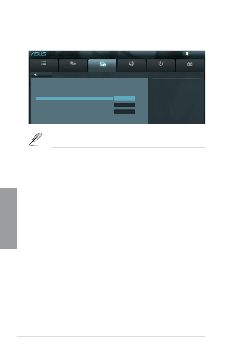
3.5.5 USB Conguration
The items in this menu allow you to change the USB-related features.
Back Advanced\ USB Conguration >
USB Conguration
USB Devices:
1 Keyboard, 1 Mouse, 2 Hubs
Legacy USB Support Enabled
Legacy USB3.0 Support Enabled
EHCI Hand-off Disabled
Legacy USB Support [Enabled]
[Enabled] Enables the support for USB devices on legacy operating systems (OS).
[Disabled] The USB devices can be used only for the BIOS setup program.
[Auto] Allows the system to detect the presence of USB devices at startup. If
Chapter 3
Legacy USB3.0 Support [Enabled]
[Enabled] Enables the support for USB 3.0 devices on legacy operating systems
[Disabled] Disables the function.
EHCI Hand-off [Disabled]
[Enabled] Enables the support for operating systems without an EHCI hand-off
[Disabled] Disables the function.
EFI BIOS Utility - Advanced Mode
Main
Ai Tweaker
Advanced Monitor Boot Tool
Enables Legacy USB support. AUTO
option disables legacy support if no
USB devices are connected. DISABLE
option will keep USB devices
available only for EFI applications.
The USB Devices item shows the auto-detected values. If no USB device is detected, the
item shows None.
detected, the USB controller legacy mode is enabled. If no USB device is
detected, the legacy USB support is disabled.
(OS).
feature.
Exit
3-20 Chapter 3: BIOS setup
Page 89

3.5.6 Onboard Devices Conguration
EFI BIOS Utility - Advanced Mode
Exit
Main
Back Advanced\ Onboard Devices Conguration >
HD Audio controller Enabled
Front Panel Type HD
SPDIF Out Type SPDIF
Renesas USB 3.0 Controller Enabled
Bluetooth Controller Enabled
VIA 1394 Controller Enabled
Marvell Storage Controller Enabled
Marvell Storage OPROM Enabled
JMB Storage Controller Enabled
JMB Storage OPROM Enabled
Display OptionRom in POST Enabled
Ai Tweaker
Version 2.00.1201. Copyright (C) 2010 American Megatrends, Inc.
Advanced Monitor Boot Tool
Scroll down to display the following items:
Realtek LAN Controller Enabled
Realtek PXE OPROM Disabled
Intel LAN Controller Enabled
Intel PXE OPROM Disabled
> Serial Port Conguration
Version 2.00.1201. Copyright (C) 2010 American Megatrends, Inc.
Enabled/Disabled Azalia HD Audio
→←: Select Screen
↑↓: Select Item
Enter: Select
+/-: Change Opt.
F1: General Help
F2: Previous Values
F5: Optimized Defaults
F10: Save ESC: Exit
F12: Print Screen
Chapter 3
HD Audio Controller [Enabled]
[Enabled] Enables the High Denition Audio Controller.
[Disabled] Disables the controller.
The following two items appear only when you set the Azalia HD Audio item to [Enabled].
Front Panel Type [HD]
Allows you to set the front panel audio connector (AAFP) mode to legacy AC’97 or high-
denition audio depending on the audio standard that the front panel audio module supports.
[HD] Sets the front panel audio connector (AAFP) mode to high denition audio.
[AC97] Sets the front panel audio connector (AAFP) mode to legacy AC’97
ASUS P8Z68 DELUXE/GEN3 3-21
Page 90

SPDIF Out Type [SPDIF]
[SPDIF] Sets to [SPDIF] for SPDIF audio output.
[HDMI] Sets to [HDMI] for HDMI audio output.
Renesas USB 3.0 Controller [Enabled]
[Enabled] Enables the USB 3.0 controller.
[Disabled] Disables the controller.
Bluetooth Controller [Enabled]
[Enabled] Enables the onboard bluetooth controller.
[Disabled] Disables the controller.
VIA 1394 Controller [Enabled]
[Enabled] Enables the onboard IEEE 1394a controller.
[Disabled] Disables the controller.
Marvell Storage Controller [AHCI Mode]
Allows you to select the Marvell storage controller operating mode.
[Disabled] Disables the controller.
[IDE Mode] Set to [IDE Mode] when you want to use the Serial ATA hard disk drives as
[AHCI Mode] Set to [AHCI Mode] when you want the SATA hard disk drives to use the
Chapter 3
Marvell Storage OPROM [Enabled]
This item appears only when you set the previous item to [Enabled] and allows you to enable
or disable the OptionRom of the Marvell storage controller.
Conguration options: [Enabled] [Disabled]
Parallel ATA physical storage devices.
AHCI (Advanced Host Controller Interface). The AHCI allows the onboard
storage driver to enable advanced Serial ATA features that increases
storage performance on random workloads by allowing the drive to
internally optimize the order of commands.
JMB Storage Controller [Enabled]
Allows you to enable or disable the JMB storage controller.
Conguration options: [Disabled] [Enabled]
If you want to use the full functin of the JMB storage contorller (ex. AHCI), we recommend
that you set this item to [Enabled] and install the JMicron JMB36X Controller Driver from
the motherboard support DVD.
JMB Storage OPROM [Enabled]
This item appears only when you set the previous item to [Enabled] and allows you to enable
or disable the OptionRom of the JMB storage controller.
Conguration options: [Enabled] [Disabled]
3-22 Chapter 3: BIOS setup
Page 91

Display OptionRom in POST [Enabled]
This item appears only when you set the JMB Storage OPROM item to [Enabled] and
allows you to display or hide the OptionRom of the JMB storage controller during POST.
Conguration options: [Enabled] [Disabled]
Intel LAN Controller [Enabled]
[Enabled] Enables the Intel LAN controller.
[Disabled] Disables the controller.
Intel PXE OPROM [Disabled]
This item appears only when you set the previous item to [Enabled] and allows you to enable
or disable the PXE OptionRom of the Intel LAN controller.
Conguration options: [Enabled] [Disabled]
Serial Port Conguration
The sub-items in this menu allow you to set the serial port conguration.
This item functions only if there is a serial port (COM1) connector on the motherboard.
Serial Port [Enabled]
Allows you to enable or disable the serial port (COM).
Conguration options: [Enabled] [Disabled]
Change Settings [IO=3F8h; IRQ=4]
Allows you to select the Serial Port base address.
Conguration options: [IO=3F8h; IRQ=4] [IO=2F8h; IRQ=3] [IO=3E8h; IRQ=4]IO=2F8h; IRQ=3] [IO=3E8h; IRQ=4]] [IO=3E8h; IRQ=4]IO=3E8h; IRQ=4]]
[IO=2E8h; IRQ=3]IO=2E8h; IRQ=3]]
ASUS P8Z68 DELUXE/GEN3 3-23
Chapter 3
Page 92

3.5.7 APM
EFI BIOS Utility - Advanced Mode
Exit
Back Advanced\ APM >
Restore AC Power Loss Power Off
Power On By PCI Disabled
Power On By PCIE Disabled
Power On By RTC Disabled
Restore AC Power Loss [Power Off]
[Power On] The system goes into on state after an AC power loss.
[Power Off] The system goes into off state after an AC power loss.
[Last State] The system goes into either off or on state, whatever the system state was
Power On By PCI [Disabled]
[Disabled] Disables the PME to wake up from S5 by PCI devices.
[Enabled] Allows you to turn on the system through a PCI LAN or modem card. This
Power On By PCIE [Disabled]
Chapter 3
[Disabled] Disables the PCIE devices to generate a wake event.
[Enabled] Enables the PCIE devices to generate a wake event.
Power On By RTC [Disabled]
[Disabled] Disables RTC to generate a wake event.
[Enabled] When set to [Enabled], the items RTC Alarm Date (Days) and Hour/
Main
Ai Tweaker
Advanced Monitor Boot Tool
Specify what state to go to when
power is re-applied after a power
failure (G3 state).
before the AC power loss.
feature requires an ATX power supply that provides at least 1A on the
+5VSB lead.
Minute/Second will become user-congurable with set values.
3-24 Chapter 3: BIOS setup
Page 93

3.6 Monitor menu
The Monitor menu displays the system temperature/power status, and allows you to change
the fan settings.
EFI BIOS Utility - Advanced Mode
Exit
Main
CPU Temperature +73ºC / +163ºF+73ºC / +163ºF
MB Temperature +31ºC / +87ºF
CPU Fan Speed 4192 RPM
CPU Fan OPT Speed N/A
Chassis Fan 1 Speed N/A
Chassis Fan 2 Speed N/A
Power Fan 1 Speed N/A
CPU Q-Fan Control Enabled
CPU Fan Speed Low Limit 600 RPM
CPU Fan Prole Standard
Chassis Q-Fan Control Enabled
Chassis Fan Speed Low Limit 600 RPM
Chassis Fan Prole Standard
Ai Tweaker
Version 2.00.1201. Copyright (C) 2010 American Megatrends, Inc.
Advanced Monitor Boot Tool
Scroll down to display the following items:
CPU Voltage +1.176 V
3.3V Voltage +3.328 V
5V Voltage +5.120 V
12V Voltage +12.192 V
Anti Surge Support Enabled
Version 2.00.1201. Copyright (C) 2010 American Megatrends, Inc.
→←: Select Screen
↑↓: Select Item
Enter: Select
+/-: Change Opt.
F1: General Help
F2: Previous Values
F5: Optimized Defaults
F10: Save ESC: Exit
F12: Print Screen
Chapter 3
CPU Temperature / MB Temperature [xxx�C/xxx�F][xxx�C/xxx�F]
The onboard hardware monitor automatically detects and displays the CPU and motherboard
temperatures. Select Ignore if you do not wish to display the detected temperatures.
CPU Fan Speed [xxxx RPM] or [Ignore] / [N/A]
CPU Fan OPT Speed [xxxx RPM] or [Ignore] / [N/A]
Chassis Fan 1/2 Speed [xxxx RPM] or [Ignore] / [N/A]
Power Fan 1 Speed [xxxx RPM] or [Ignore] / [N/A]
The onboard hardware monitor automatically detects and displays the CPU, chassis,
and power fan speed in rotations per minute (RPM). If the fan is not connected to the fan speed in rotations per minute (RPM). If the fan is not connected to the
motherboard, the eld shows N/A. Select Ignore if you do not wish to display the detected
speed.
ASUS P8Z68 DELUXE/GEN3 3-25
Page 94

CPU Q-Fan Control [Enabled]
[Disabled] Disables the CPU Q-Fan control feature.
[Enabled] Enables the CPU Q-Fan control feature.
CPU Fan Speed Low Limit [600 RPM]
This item appears only when you enable the CPU Q-Fan Control feature and allows you to
disable or set the CPU fan warning speed.
Conguration options: [Ignore] [200 RPM] [300 RPM] [400 RPM] [500 RPM] [600 RPM]
CPU Fan Profile [Standard]
This item appears only when you enable the CPU Q-Fan Control feature and allows
you to set the appropriate performance level of the CPU fan.
[Standard] Sets to [Standard] to make the CPU fan automatically adjust depending on
[Silent] Sets to [Silent] to minimize the fan speed for quiet CPU fan operation.
[Turbo] Sets to [Turbo] to achieve maximum CPU fan speed.
[Manual] Sets to [Manual] to assign detailed fan speed control parameters.
Chapter 3
the CPU temperature.
The following four items appear only when you set CPU Fan Prole to [Manual].
CPU Upper Temperature [70]
Use the <+> and <-> keys to adjust the upper limit of the CPU temperature. The values range
from 40ºC to 90ºC.
CPU Fan Max. Duty Cycle(%) [100]
Use the <+> and <-> keys to adjust the maximum CPU fan duty cycle. The values range from
20% to 100%. When the CPU temperature reaches the upper limit, the CPU fan will operate at
the maximum duty cycle.
CPU Lower Temperature [20]
Displays the lower limit of the CPU temperature.
CPU Fan Min. Duty Cycle(%) [20]
Use the <+> and <-> keys to adjust the minimum CPU fan duty cycle. The values range from 0% minimum CPU fan duty cycle. The values range from 0%The values range from 0%
to 100%. When the CPU temperature is under 40ºC, the CPU fan will operate at the minimumWhen the CPU temperature is under 40ºC, the CPU fan will operate at the minimum
duty cycle.
Chassis Q-Fan Control [Enabled]
[Disabled] Disables the Chassis Q-Fan control feature.
[Enabled] Enables the Chassis Q-Fan control feature.
Chassis Fan Speed Low Limit [600 RPM]
This item appears only when you enable the Chassis Q-Fan Control feature and allows you
to disable or set the chassis fan warning speed.
Conguration options: [Ignore] [200 RPM] [300 RPM] [400 RPM] [500 RPM] [600 RPM]
3-26 Chapter 3: BIOS setup
Page 95

Chassis Fan Profile [Standard]
This item appears only when you enable the Chassis Q-Fan Control feature and
allows you to set the appropriate performance level of the chassis fan.
[Standard] Sets to [Standard] to make the chassis fan automatically adjust depending
on the chassis temperature.
[Silent] Sets to [Silent] to minimize the fan speed for quiet chassis fan operation.
[Turbo] Sets to [Turbo] to achieve maximum chassis fan speed.
[Manual] Sets to [Manual] to assign detailed fan speed control parameters.
The following four items appear only when you set Chassis Fan Prole to [Manual].
Chassis Upper Temperature [70]
Use the <+> and <-> keys to adjust the upper limit of the CPU temperature. The values range
from 40ºC to 90ºC.
Chassis Fan Max. Duty Cycle(%) [100]
Use the <+> and <-> keys to adjust the maximum chassis fan duty cycle. The values range
from 20% to 100%. When the chassis temperature reaches the upper limit, the chassis fan will
operate at the maximum duty cycle.
Chassis Lower Temperature [40]
Displays the lower limit of the chassis temperature.
CPU Fan Min. Duty Cycle(%) [60]
Use the <+> and <-> keys to adjust the minimum chassis fan duty cycle. The values range from
0% to 100%. When the chassis temperature is under 40ºC, the chassis fan will operate at the
minimum duty cycle.
CPU Voltage, 3.3V Voltage, 5V Voltage, 12V Voltage
The onboard hardware monitor automatically detects the voltage output through the onboard
voltage regulators. Select Ignore if you do not want to detect this item.
Anti Surge Support [Enabled]
This item allows you to enable or disable the Anti Surge function.
Conguration options: [Disabled] [Enabled]
ASUS P8Z68 DELUXE/GEN3 3-27
Chapter 3
Page 96

3.7 Boot menu
The Boot menu items allow you to change the system boot options.
Bootup NumLock State On
Full Screen Logo Enabled
Wait for ‘F1’ If Error Enabled
Option ROM Messages Force BIOS
Setup Mode EZ Mode
Boot Option Priorities
Boot Option #1 P3: xxxxxxx
Boot Option #2 P4: xxxxxxx
Boot Override
> P5: xxxxxxxxxxxx
> P6: xxxxxxxxxxxx
> Hard Drive BBS Priorities
> CD/DVD ROM Drive BBS Priorities
Bootup NumLock State [On]
Chapter 3
[On] Sets the power-on state of the NumLock to [On].
[Off] Sets the power-on state of the NumLock to [Off].
Full Screen Logo [Enabled]
[Enabled] Enables the full screen logo display feature.
[Disabled] Disables the full screen logo display feature.
EFI BIOS Utility - Advanced Mode
Main
Ai Tweaker
Version 2.00.1201. Copyright (C) 2010 American Megatrends, Inc.
Advanced Monitor Boot Tool
Select the keyboard NumLock state
→←: Select Screen
↑↓: Select Item
Enter: Select
+/-: Change Opt.
F1: General Help
F2: Previous Values
F5: Optimized Defaults
F10: Save ESC: Exit
F12: Print Screen
Exit
Set this item to [Enabled] to use the ASUS MyLogo 2™ feature.
Wait For ‘F1’ If Error [Enabled]
[Disabled] Disables this function.
[Enabled] The system waits for the <F1> key to be pressed when error occurs.
Option ROM Messages [Force BIOS]
[Force BIOS] The third-party ROM messages will be forced to display during the boot
[Keep Current] The third-party ROM messages will be displayed only if the third-party
3-28 Chapter 3: BIOS setup
sequence.
manufacturer had set the add-on device to do so.
Page 97

Setup Mode [EZ Mode]
[Advanced Mode] Sets Advanced Mode as the default screen for entering the BIOS setup
[EZ Mode] Sets EZ Mode as the default screen for entering the BIOS setup program.
program.
Boot Option Priorities
These items specify the boot device priority sequence from the available devices. The
number of device items that appears on the screen depends on the number of devices
installed in the system.
• To select the boot device during system startup, press <F8> when ASUS Logo appears.
• To access Windows OS in Safe Mode, do any of the following:
- Press <F5> when ASUS Logo appears.
- Press <F8> after POST.
Boot Override
These items displays the available devices. The number of device items that appears on
the screen depends on the number of devices installed in the system. Click an item to start
booting from the selected device.
3.8 Tools menu
The Tools menu items allow you to congure options for special functions. Select an item
then press <Enter> to display the submenu.
EFI BIOS Utility - Advanced Mode
Main
> ASUS EZ Flash 2 Utility
> ASUS O.C. Prole
> ASUS SPD Information
Ai Tweaker
Advanced Monitor Boot Tool
Be used to update BIOS
Exit
3.8.1 ASUS EZ Flash 2 Utility
Allows you to run ASUS EZ Flash 2. When you press <Enter>, a conrmation message
appears. Use the left/right arrow key to select between [Yes] or [No], then press <Enter> to
conrm your choice.
For more details, refer to section 3.10.2 ASUS EZ Flash 2 utility.
ASUS P8Z68 DELUXE/GEN3 3-29
Chapter 3
Page 98

3.8.2. ASUS O.C. Prole
This item allows you to store or load multiple BIOS settings.
Back Tool\ ASUS O.C. Prole >
O.C. Prole Conguration
Setup Prole 1 Status : Not Installed
Setup Prole 2 Status : Not Installed
Setup Prole 3 Status : Not Installed
Setup Prole 4 Status : Not Installed
Setup Prole 5 Status : Not Installed
Setup Prole 6 Status : Not Installed
Setup Prole 7 Status : Not Installed
Setup Prole 8 Status : Not Installed
Add Your CMOS Prole
Label
Save to Prole 1
Add Your CMOS Prole
Load from Prole 1
Save to Prole
Allows you to save the current BIOS settings to the BIOS Flash, and create a prole. Key in a
prole number from one to eight, press <Enter>, and then select Yes.
Chapter 3
Load from Prole
Allows you to load the previous BIOS settings saved in the BIOS Flash. Key in the proleKey in the prole
number that saved your BIOS settings, press <Enter>, and then select Yes.
EFI BIOS Utility - Advanced Mode
Main
Ai Tweaker
Advanced Monitor Boot Tool
The Setup Prole Status items show Not Installed if no prole is created.
Exit
Save BIOS settings to Prole
• DO NOT shut down or reset the system while updating the BIOS to prevent the
system boot failure!
• We recommend that you update the BIOS le only coming from the same memory/CPU
conguration and BIOS version.
3-30 Chapter 3: BIOS setup
Page 99

3.9 Exit menu
The Exit menu items allow you to load the optimal default values for the BIOS items, and
save or discard your changes to the BIOS items. You can access the EZ Mode from the Exit
menu.
Exit
Load Optimized Defaults
Save Changes & Reset
Discard Changes & Exit
ASUS EZ Mode
Launch EFI Shell from lesystem device
Load Optimized Defaults
This option allows you to load the default values for each of the parameters on the Setup
menus. When you select this option or if you press <F5>, a conrmation window appears.
Select Yes to load the default values.
Save Changes & Reset
Once you are nished making your selections, choose this option from the Exit menu to
ensure the values you selected are saved. When you select this option or if you press <F10>,
a conrmation window appears. Select Yes to save changes and exit.
Discard Changes & Exit
This option allows you to exit the Setup program without saving your changes. When youWhen you
select this option or if you press <Esc>, a conrmation window appears. Select Yes to
discard changes and exit..
ASUS EZ Mode
This option allows you to enter the EZ Mode screen.
Launch EFI Shell from lesystem device
This option allows you to attempt to launch the EFI Shell application (shellx64.e) from one of
the available lesystem devices.
ASUS P8Z68 DELUXE/GEN3 3-31
Chapter 3
Page 100

3.10 Updating BIOS
The ASUS website publishes the latest BIOS versions to provide enhancements on system
stability, compatibility, or performance. However, BIOS updating is potentially risky. If there
is no problem using the current version of BIOS, DO NOT manually update the BIOS.
Inappropriate BIOS updating may result in the system’s failure to boot. Carefully follow the
instructions of this chapter to update your BIOS if necessary.
The following utilities allow you to manage and update the motherboard BIOS setup program.
1. ASUS Update: Updates the BIOS in Windows® environment.
2. ASUS EZ Flash 2: Updates the BIOS using a USB ash drive.
3. ASUS CrashFree BIOS 3: Restores the BIOS using the motherboard support DVD or
a USB ash drive when the BIOS le fails or gets corrupted.
4. ASUS BIOS Updater: Updates and backups the BIOS in DOS environment using the
motherboard support DVD and a USB ash disk drive.
Refer to the corresponding sections for details on these utilities.
3.10.1 ASUS Update utility
Chapter 3
The ASUS Update is a utility that allows you to manage, save, and update the motherboard
BIOS in Windows® environment. The ASUS Update utility allows you to:
• Update the BIOS directly from the Internet
• Download the latest BIOS le from the Internet
• Update the BIOS from an updated BIOS le
• Save the current BIOS le
• View the BIOS version information
This utility is available in the support DVD that comes with the motherboard package.
Visit the ASUS website (www.asus.com) to download the latest BIOS le for this
motherboard.
Save a copy of the original motherboard BIOS le to a USB ash disk in case you need
to restore the BIOS in the future. Copy the original motherboard BIOS using the ASUS
Update or BIOS Updater utilities.
ASUS Update requires an Internet connection either through a network or an Internet
Service Provider (ISP).
Launching ASUS Update
After installing AI Suite II from the motherboard support DVD, launch ASUS Update by
clicking Update > ASUS Update on the AI Suite II main menu bar.
Quit all Windows® applications before you update the BIOS using this utility.
3-32 Chapter 3: BIOS setup
 Loading...