

Page 1

R
AP5000
Dual Pentium® II Server Platform
Installation Guide
Page 2

USER’S NOTICE
No part of this manual, including the products and software described in it, may be
reproduced, transmitted, transcribed, stored in a retrieval system, or translated into
any language in any form or by any means, except documentation kept by the purchaser for backup purposes, without the express written permission of ASUSTeK
COMPUTER INC. (“ASUS”).
ASUS PROVIDES THIS MANUAL “AS IS” WITHOUT WARRANTY OF ANY
KIND, EITHER EXPRESS OR IMPLIED, INCLUDING BUT NOT LIMITED
TO THE IMPLIED WARRANTIES OR CONDITIONS OF MERCHANTABILITY OR FITNESS FOR A PARTICULAR PURPOSE. IN NO EVENT SHALL
ASUS, ITS DIRECTORS, OFFICERS, EMPLOYEES OR AGENTS BE LIABLE
FOR ANY INDIRECT , SPECIAL, INCIDENT AL, OR CONSEQUENTIAL DAMAGES (INCLUDING DAMAGES FOR LOSS OF PROFITS, LOSS OF BUSINESS, LOSS OF USE OR DATA, INTERRUPTION OF BUSINESS AND THE
LIKE), EVEN IF ASUS HAS BEEN ADVISED OF THE POSSIBILITY OF SUCH
DAMAGES ARISING FROM ANY DEFECT OR ERROR IN THIS MANUAL
OR PRODUCT.
Product warranty or service will not be extended if: (1) the product is repaired,
modified or altered, unless such repair, modification of alteration is authorized in
writing by ASUS; or (2) the serial number of the product is defaced or missing.
Products and corporate names appearing in this manual may or may not be registered trademarks or copyrights of their respective companies, and are used only for
identification or explanation and to the owners’ benefit, without intent to infringe.
• Intel, LANDesk, and Pentium are registered trademarks of Intel Corporation.
• IBM and OS/2 are registered trademarks of International Business Machines.
• Symbios is a registered trademark of Symbios Logic Corporation.
• Windows and MS-DOS are registered trademarks of Microsoft Corporation.
• Sound Blaster AWE32 and SB16 are trademarks of Creative Technology Ltd.
• Adobe and Acrobat are registered trademarks of Adobe Systems Incorporated.
The product name and revision number are both printed on the product itself. Manual
revisions are released for each product design represented by the digit before and
after the period of the manual revision number . Manual updates are represented by
the third digit in the manual revision number.
For previous or updated manuals, BIOS, drivers, or product release information, contact ASUS at http://www.asus.com.tw or through any of the means indicated on the
following page.
SPECIFICA TIONS AND INFORMA TION CONTAINED IN THIS MANUAL ARE
FURNISHED FOR INFORMATIONAL USE ONLY, AND ARE SUBJECT TO
CHANGE AT ANY TIME WITHOUT NOTICE, AND SHOULD NOT BE CONSTRUED AS A COMMITMENT BY ASUS. ASUS ASSUMES NO RESPONSIBILITY OR LIABILITY FOR ANY ERRORS OR INACCURACIES THAT MAY
APPEAR IN THIS MANUAL, INCLUDING THE PRODUCTS AND SOFTWARE
DESCRIBED IN IT.
Copyright © 1998 ASUSTeK COMPUTER INC. All Rights Reserved.
Product Name: ASUS AP5000
Manual Revision: 1.00
Release Date: May 1998
2
ASUS AP5000 Installation Guide
Page 3

ASUS CONTACT INFORMATION
ASUSTeK COMPUTER INC.
Marketing
Address: 150 Li-Te Road, Peitou, Taipei, Taiwan 112
Telephone: +886-2-2894-3447
Fax: +886-2-2894-3449
Email: info@asus.com.tw
Technical Support
Fax: +886-2-2895-9254
BBS: +886-2-2896-4667
Email: tsd@asus.com.tw
WWW: www.asus.com.tw
FTP: ftp.asus.com.tw/pub/ASUS
ASUS COMPUTER INTERNATIONAL
Marketing
Address: 6737 Mowry Ave, Mowry Business Center, Building 2,
Newark, CA 94560, USA
Fax: +1-510-608-4555
Email: info-usa@asus.com.tw
Technical Support
Fax: +1-510-608-4555
BBS: +1-510-739-3774
Email: tsd-usa@asus.com.tw
WWW: www.asus.com
FTP: ftp.asus.com.tw/pub/ASUS
ASUS COMPUTER GmbH
Marketing
Address: Harkort Str. 25, 40880 Ratingen, BRD, Germany
Telephone: 49-2102-445011
Fax: 49-2102-442066
Email: info-ger@asus.com.tw
Technical Support
Hotline: 49-2102-499712
BBS: 49-2102-448690
Email: tsd-ger@asus.com.tw
WWW: www.asuscom.de
FTP: ftp.asuscom.de/pub/ASUSCOM
ASUS AP5000 Installation Guide 3
Page 4

(This page was intentionally left blank)
4
ASUS AP5000 Installation Guide
Page 5

CONTENTS
I. INTRODUCTION............................................................................7
Preface .............................................................................................7
II. BARE-BONE KITS........................................................................9
Bare-Bone Kits Overview................................................................9
HOUSING .......................................................................................9
MOTHERBOARD.........................................................................10
DRIVE BAY ..................................................................................11
BACK PLANE BOARD ...............................................................11
SLOT CARD .................................................................................12
III. INTEGRATION ..........................................................................15
PROCEDURES .............................................................................15
SYSTEM UNIT .............................................................................15
Opening the cover ..........................................................................15
Inserting the motherboard ..............................................................16
Installing the memory and power I/O cables .................................17
Installing the CPU..........................................................................17
Installing the memory ..............................................................18
Installing a VGA or PCI add-on card .......................................18
Installing the ATX power switch and other signal pins............18
Closing the cover......................................................................19
CABLING......................................................................................20
DRIVE SETUP ..............................................................................20
Installing a slot card .................................................................21
SAF-TE back plane boards.................................................21
NON SAF-TE back plane boards .......................................22
Indicator lights .........................................................................23
Installing SCSI devices ..................................................................24
Drive locations ...............................................................................24
BACK PLANE BOARD INSTALLATION ..................................26
Integrating the DA-BP4-1(S) ...................................................26
Integrating with the housing.....................................................27
Connecting the SCSI cables .....................................................27
Installing the disk drive bay to the back plane board...............28
POWER SUPPLY UNIT................................................................29
Replacements ...........................................................................29
ASUS AP5000 Installation Guide 5
Page 6
FCC & DOC COMPLIANCE
Federal Communications Commission Statement
This device complies with FCC Rules Part 15. Operation is subject to the
following two conditions:
• This device may not cause harmful interference, and
• This device must accept any interference received, including interference that may cause undesired operation.
This equipment has been tested and found to comply with the limits for a
Class B digital device, pursuant to Part 15 of the FCC Rules. These limits
are designed to provide reasonable protection against harmful interference
in a residential installation. This equipment generates, uses and can radiate
radio frequency energy and, if not installed and used in accordance with
manufacturer’s instructions, may cause harmful interference to radio communications. However, there is no guarantee that interference will not occur in a particular installation. If this equipment does cause harmful interference to radio or television reception, which can be determined by turning the equipment off and on, the user is encouraged to try to correct the
interference by one or more of the following measures:
• Reorient or relocate the receiving antenna.
• Increase the separation between the equipment and receiver.
• Connect the equipment to an outlet on a circuit different from that to
which the receiver is connected.
• Consult the dealer or an experienced radio/TV technician for help.
WARNING! The use of shielded cables for connection of the monitor
to the graphics card is required to assure compliance with FCC regulations. Changes or modifications to this unit not expressly approved by
the party responsible for compliance could void the user’s authority to
operate this equipment.
Canadian Department of Communications Statement
This digital apparatus does not exceed the Class B limits for radio noise
emissions from digital apparatus set out in the Radio Interference Regulations of the Canadian Department of Communications.
6
ASUS AP5000 Installation Guide
Page 7

I. INTRODUCTION
Preface
A Guide to build up the ASUSTeK newer and more powerful server system:
AP5000.
The AP5000 uses the P2L97-DS smart motherboard as its base to support
dual Pentium II processor . W ith a built-in AGP slot, the AP5000 can be both
a server and workstation. The following introductions will guide you to
understand and build up such a best system - AP5000.
Two sections will be introduced as following:
* Bare-Bone Kits Overview
* Integration Procedure
Preface
I. INTRODUCTION
ASUS AP5000 Installation Guide 7
Page 8

I. INTRODUCTION
I. INTRODUCTION
(This page was intentionally left blank)
8 ASUS AP5000 Installation Guide
Page 9
II. BARE-BONE KITS
Bare-Bone Kits Overview
This section will show you the component kits of AP5000 including
housing, motherboard, CPU card, device drive-bay, back plane board,
and slot card.
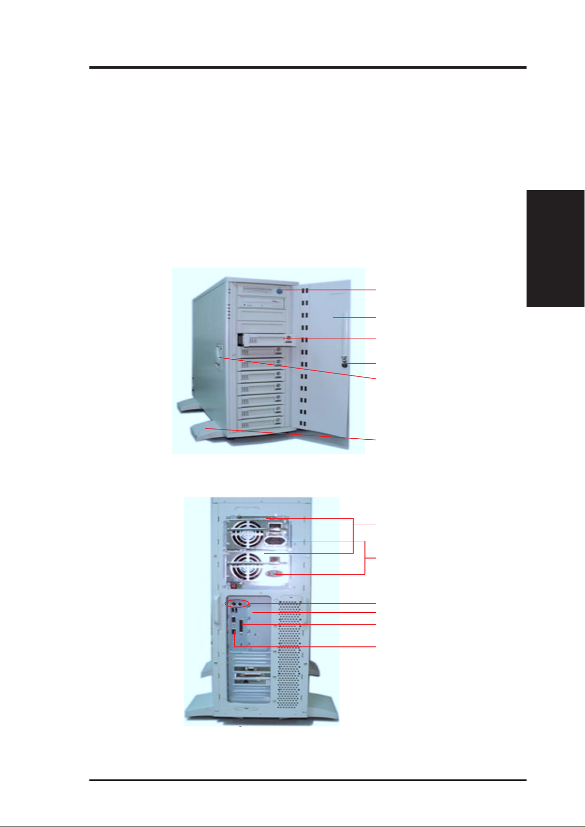
HOUSING
The housing of the AP5000 is ivory white. Its front and back view after
system assembly is shown below:
Power button
Front door
Device drive-bay
II. BARE-BONE KITS
Fig 2-1: Front view of housing
Key locker of front door
Cover install/
remove locker
Tower feet with wheel
Redundant power supply
Power connectors
Parallel I/O port
Fig 2-2: Back side of housing
ASUS AP5000 Installation Guide 9
Serial I/O port
Page 10
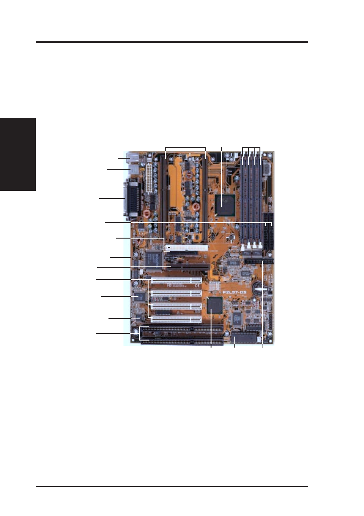
MOTHERBOARD
The AP5000 uses the P2L97-DS motherboard which is designed to support
dual Pentium II processors. For detailed specifications, refer to the P2L97DS user’s manual.
II. BARE-BONE KITS
II. BARE-BONE KITS
PS/2 Mouse (Top)
PS/2 K’Board (Bottom)
USB Port 1 (Top)
USB Port 2 (Bottom)
Parallel (T op)
Primary/Secondary
IDE Connectors
Narrow/Wide SCSI
Connectors (optional)
Adaptec’s 7880
Fast/Wide SCSI Chipset
(optional)
Accelerated
Graphics Port
4 PCI Slots
Multi-I/O Chip
SEC CPU Slots
Intel 440LX
AGPset
DIMM Sockets
Hardware Monitor
(optional)
2 ISA Slots
Fig 2-3: P2L97-DS Layout
Intel PIIX4 PCIset
Programmable
2Mbit Flash ROM
Floppy Disk
Drive
Connector
10 ASUS AP5000 Installation Guide
Page 11

II. BARE-BONE KITS
DRIVE BAY
There are two types of drive bays, that could mount, floppy drive, CDROM drive and hard disk drive. One type is fixed type and another is
removable type which has key-lock feature, refer to the following figures:
Fig 2-4: Fixed type drive bay
Fig 2-5: Hot-Swap drive bay
II. BARE-BONE KITS
BACK PLANE BOARD
The ASUS Back Plane Board, DA-BP4 series, were designed for carrying
four removable SCSI devices per Back Plane Board. Normally those removable SCSI drives are installed on the Hot-Swap Drive Bay with a small
slot card connected together (Fig 2-7). When the completed drive set plugs
in, the slot board of drive Bay and bus of DA-BP4 will be connected together. After that, all the four SCSI-ID of SCSI devices could be managed
from the switches of Back Plane Board (Fig 2-6). Moreover there are two
models of Back Plane Boards available for none SAF-TE and SAF-TE which
are named DA-BP4-1 and DA-BP4-1S. SAF-TE one mounted one more
management chip named GEM200RE in which could provide additional
status information of device drives (Detail refer to chapter 3).
Fig 2-6: DA-BP4 series Back Plane Board
ASUS AP5000 Installation Guide 11
Page 12

II. BARE-BONE KITS
SLOT CARD
The ASUS slot card is DA-BC68 which uses for wide SCSI. Its jumpers and
connectors are shown on Fig:2-7. It will setup with Hot-Swap drive bay.
II. BARE-BONE KITS
Fig 2-7: Jumper & Connector of Slot Card
Golden Finger Bus of Slot Card None DA-BP4-1S
Power Cable Power of SCSI drive None SCSI drive
SCSI connector Connector of wide SCS I DA-BP4-1S
SCSI_ID
(8-pin)
ALED_IN
(2-pin)
KEY SLED PLED ALED_IN SCSI_ID
SCSI Connector
Golden Finger
Power Cable
Items Functions Cables Uses Connect T o
68-pin wide SCSI
cable
SCSI ID could be managed
from DA-BP4-1(S), refer to
Fig: 3-28
Jumper of device accessing
SCSI_ID cable, 8wire,
ALED_IN cable, 2wire, (Red/Black)
ID jumper of
SCSI drive.
*Be sure the
target SCSI ID is
in the right order.
Access jumper of
SCSI drive
PLED (3-pin) Power LED
SLED (3-pin) Status LED
KEY (2-pin) Insure the SCSI drive power
has been off while Key Lock of
Drive Bay being opened. T o
protect device during hotswap.
PLED cable, 3-wire,
(Orange/Black/
Green)
SLED cable, 3-wire,
(Green/Black/Red)
KEY cable, 2-wire,
(Black/Red)
Table 2-1: Jumper of Slot Card with SAF-TE Back Plane Board
12 ASUS AP5000 Installation Guide
Light-1 of Drive
Bay
Light-2 of Drive
Bay
Key Lock of Drive
Bay
Page 13

II. BARE-BONE KITS
Items Functions Cables Uses Connect T o
Golden Finger Bus of Slot Card None DA-BP4-1
Power Cable Power of SCSI drive None SCSI drive
SCSI connector Connector of wide SCS I DA-BP4-1
SCSI_ID (8-pin)
ALED_IN(2-pin)
SLED (3-pin) None None **None
PLED (3-pin) Power LED
KEY (2-pin)
SCSI ID could be managed
from DA-BP4-1(S), refer to
Fig: 3-28
None
Insure the SCSI drive
power has been off while
Key Lock of Drive Bay
being opened. T o pr otect
device during hot-swap.
68-pin wide SCSI
cable
SCSI_ID cable, 8wire,
None **None
PLED cable, 3wire, (Orange/
Black/Green)
KEY cable, 2-wire,
(Black/Red)
ID jumper of
SCSI drive.
*Be sure the
target SCSI ID is
in the right order.
Light-1 of Drive
Bay
Key Lock of
Drive Bay
Table 2-2: Jumper of Slot Card with none SAF-TE Back
Plane Board
** The ALED_IN and SLED jumpers of slot card will be no function if the
Back Plane Board is none SAF-TE, thus they should not connect any cable
on these two jumpers. But the ALED_IN (from SCSI drive) cable and SLED
cable (from Drive Bay) must be connected together directly in order to light
up on Light-2 (Fig: 2-8) of Drive Bay during SCSI device access.
II. BARE-BONE KITS
Fig 2-8: Indicator Light of Drive Bay
ASUS AP5000 Installation Guide 13
Key Lock
Light-2 (SLED)
Light-1 (PLED)
Page 14

(This page was intentionally left blank)
II. BARE-BONE KITS
II. BARE-BONE KITS
14 ASUS AP5000 Installation Guide
Page 15

III. INTEGRATION
PROCEDURES
Along with previous product shipping kits, this section will introduce you on
how to integrate an AP5000 together, and some of the notices you need to be
aware of during installation. The step-by-step procedures have divided to five
topics which are System Unit Integration, CPU Card Installation, Cabling,
Device Drives, Installation, and Back Plane Board Installation.
SYSTEM UNIT
System assembly steps are as follows:
1. Open cover.
2. Remove fan frame.
3. Install the motherboard.
4. Install the CPU, memory, and add-on cards.
Opening the cover
Remove the four screws in the back of the system (Fig 3-1). Follow the
direction on the cover locker to release (Fig 3-2) and remove the cover of
housing (Fig 3-3).
Fig 3-1: Open the cover-locker
Procedures
III. INTEGRATION
Fig 3-2: Release cover lock
ASUS AP5000 Installation Guide 15
Fig 3-3: Remove the cover
Page 16

III. INTEGRATION
III. INTEGRATION
Inserting the motherboard
Set the system down with on a level surface with the open side facing up.
Remove the system fan frame module (Fig 3-4). Put the motherboard support (spacer) in order to balance the power of plugging add-on and CPU
cards (Fig 3-5), then place the motherboard into the housing (Fig 3-6). Next,
screw the motherboard into the housing (Fig 3-7). Please do not over tighten
as this may damage the surface of the motherboard.
Fig 3-4: Remove Fan Frame
Fig 3-5: Put in Main Board Spacer
Fig 3-6: Place the motherboard
Spacer
Fig 3-7: Motherboard installed
16 ASUS AP5000 Installation Guide
Page 17

III. INTEGRATION
Installing the memory and power I/O cables
Next, install the memory, power cable, serial/parallel/VGA brackets, and
HDD/FDD cable (Fig 3-8). For more details about cable paths of device
drives, refer to Cabling (p.20).
I/O ports and brackets
Power connector
SCSI hard disk
connector
Memory
FDD cable connector
Fig 3-8: Installation of Cables, Memory and I/O brackets
Installing the CPU
Pull back the fan frame (Fig 3-9), and install the CPU (Fig 3-10).
Fig 3-9: Pull back the fan frame
Insert the CPU into the retention module. If you only have one CPU, insert
a termination card into the other CPU slot.
III. INTEGRATION
Fig 3-10: Insert CPU
ASUS AP5000 Installation Guide 17
Page 18

III. INTEGRATION
III. INTEGRATION
Installing the memory
Insert the SDRAM (168-pin) into the DIMM socket (Fig 3-11).
Fig 3-11: Insert the SDRAM
Installing a VGA or PCI add-on card
Insert a VGA or PCI add-on card into the PCI slot.
Fig 3-12: Insert a VGA/ PCI add-on card
Installing the ATX power switch and other signal pins
Refer to the P2L97-DS user’s manual to install the ATX power switch pin,
system indicator pin, and IDE device indicator pin. (Fig 3-13).
ATX power switch pin
System power indicator pin
IDE device indicator pin
Fig 3-13
Secure the power switch next to the FDD with screws (Fig 3-13).
Fig 3-14
18 ASUS AP5000 Installation Guide
Page 19

III. Integration Procedures
Closing the cover
Follow the figures below (Fig 3-15, 3-16, 3-17) to complete the hardware installation.
Fig 3-15: CPU and motherboard installed
Fig 3-16: Replace the cover
III. Integration
Closing the Cover
Fig 3-17: Lock the cover
ASUS AP5000 Installation Guide 19
Page 20

III. Integration
Connections
III. Integration Procedures
CABLING
There are three sets of cables, and their locations are indentified in Fig
3-18 and Fig 3-19.
Cabling path for CD-ROM/IDE
drives
Cabling path for Floppy
Cabling path for SCSI hard disk
Fig 3-18: Cable locations
Cabling path for Floppy/CD-ROM/IDE drives
Cabling path for SCSI
Fig 3-19: Cable Path of Floppy, IDE, CD-ROM, and SCSI
DRIVE SETUP
T o install device drives on fix-type drive bay is quite straight forward, simply by screwing the device, inserting it to housing and down at connecting
necessary cables. But for Hot-Swap drive bay, the cables connecting and
means of indicator light on drive bay are quite complex. This section shows
that the installation of slot card with drive bay, the specification of indicator light, device installation and the recommendation of drive position on
the housing.
20 ASUS AP5000 Installation Guide
Page 21

III. Integration Procedures
Installing a slot card
To install a slot card with a Hot-Swap drive bay, there are two types of
cabling methods as shown below; One is for SAF-TE back plane boards
(Fig: 3-20), another is for none SAF-TE back plane boards (Fig: 3-21).
SAF-TE back plane boards
To install SAF-TE one, the five cables should connect to the slot card and
the connections on the other end should be; two cables for SCSI device and
the other three for drive bay, shown below:
KEY SLED PLED ALED_IN SCSI_ID
Jumpers for Drive Bay
CAUTION
* PLED cable, 3-wire (Orange/Black/
Green), connects Green to position #1
of PLED jumper.
* SLED cable, 3-wir e (Green/Black/Red)
connects Red to position #1 of SLED
jumper.
* KEY cable, 2-wir e (Black/Red) connects
Black to position #1 of KEY jumper.
111
Jumpers for SCSI Drive
* SCSI_ID cable, 8-wire, connects be-
tween SCSI_ID jumper of slot card and
ID jumper of SCSI drive. Be sure their
SCSI ID matched
* ALED_IN cable, 2-wire, connects be-
tween ALED_IN of slot card and access
jumper of SCSI drive.
Connections
III. Integration
Fig 3-20: Jumper Location & Cabling with SAF-TE Features
ASUS AP5000 Installation Guide 21
Page 22

III. Integration
Procedures
III. Integration Procedures
NON SAF-TE back plane boards
T o install a slot card for a non SAF-TE back plane board, three cables connect to slot
card shown below, one (SCSI_ID) for SCSI device and the other two (KEY and
PLED) for drive bay. And for the two unconnected cables; SLED and ALED_IN
cables, they should be connected together, so that the SCSI device access status will
present to Light-2 (STATUS LED) of drive bay directly without going through the
slot card, because there is no function for this two jumper on slot card if the Back
Plane Board is non SAF -TE.
KEY SLED PLED ALED_IN SCSI_ID
CAUTION
* PLED cable, 3-wire (Orange/Black/
Green), connects Green to position #1 of
PLED jumper.
* KEY cable, 2-wire (Black/Red) connects
Black to position #1 of KEY jumper .
1 1 1
Jumpers for Drive Bay
Jumpers for SCSI Drive
SLED and ALED_IN
cables link together in
between by this jumper. The
direction should be Green
wire of SLED cable to Red
wire of ALED-IN cable.
* SCSI_ID cable, 8-wir e, connects between
SCSI_ID jumper of slot card and ID
jumper of SCSI drive. Be sure their SCSI
ID matched
Fig 3-21: Jumper Location & Cabling with non SAF-TE Features
22 ASUS AP5000 Installation Guide
Page 23

III. Integration Procedures
Indicator lights
This section shows that the indicator light (Fig 3-22) specification of both
Back Plane Board SAF-TE (Table 3-1) and back plane board non SAF-TE
(Table 3-2). Also the Key lock is used to insure the power is entirely being
off while Key Lock is opened during the process of hot swap.
Key Lock
Light-2 (SLED)
Light-1 (PLED)
Fig 3-22: Indicator Light of Drive Bay
Device Status Indicator Light-1 Indicate Light-2 Color of Light
No Error OFF NO NO
Faulty ON OFF Red
Identify Alternating Fast Blink (3 /sec) Red/Green
between Light-1 and Light-2
Rebuild OFF Fast Blink (3 /sec) Green
Rebuild Stopped OFF ON Green
Ready for Insertion/Removal ON ON Yellow
Predicated Fault Fast Blink (3 /sec) OFF Red
Hot Spare Fast Blink (3 /sec) Fast Blink (3 /sec) Yellow
In Failed Array Fast Blink (3 /sec) ON Red/Yellow
In Critical Array Slow Blink (1 /sec) OFF Red
Requirements
III. Integration
Table 3-1: Device Indicator Specification of SAF-TE
Device Status Indicator Light-1 Indicate Light-2
Power ON OFF
Drive Access ON Blink
Table 3-2: Device Indicator Specification of Non SAF-TE
ASUS AP5000 Installation Guide 23
Page 24

Installing SCSI devices
Next to previous section, the integrated drive bay shown on Fig: 3-23. Then
place the SCSI device on to drive bay and connect necessary cables from
both drive bay and slot card to SCSI device including SCSI cable, power
cable, access status cable and SCSI ID cable. Especially be sure the 8-pin
SCSI ID cable is connecting with correspondent SCSI ID on both SCSI
drive and slot card (Fig: 3-24). Finally screw in the SCSI drive with drive
bay (Fig: 3-25).
III. Integration
SCSI Devices
Fig 3-23: Integrated Drive Bay
III. Integration Procedures
Fig 3-24: Necessary Cables Connect to SCSI device both Front and Back.
Fig 3-25: Screw in device on Drive Bay
Drive locations
The recommendation of drives location is that first top drive used for floppy ,
second for CD-ROM and the rest could be used for Hot-Swap drive bays
(Fig: 3-26). All the devices either carried on Hot-Swap drive bay or FixedType driver bay, should be inserted to housing from the front of housing.
24 ASUS AP5000 Installation Guide
Page 25

III. Integration Procedures
There are types of front covers for floppy , CD-ROM drive, HDD or nothing
installed (refer to Fig-27). Finally after drives are being installed, please
close or lock the front door of the AP5000 to protect them.
Hot-Swap drive bay does not
require a cover.
Fig 3-26: Drive setup
Fig 3-27: 3 types of drive covers
To remove a drive cover, first release the two retainers on each side of the
cover by pressing them in and then out toward the front with a screwdriver
(Fig 3-28). Carefully remove the drive cover from the front using a screwdriver (Fig 3-29).
Fig 3-28
Drive Setup
III. Integration
Fig 3-29
ASUS AP5000 Installation Guide 25
Page 26

BACK PLANE BOARD INSTALLATION
To install Back Plane Board, first we have to integrate DA-BP4-1(S) with
its box, then install on to housing. This section will show you these. Also
enclose the specification sets of jumper and switches.
Integrating the DA-BP4-1(S)
The ASUS DA-BP4-1(S) contains one SCSI connector that will connect to
on-board SCSI port of AP5000, and its back has four PCI slots connecting
to slot card of drive bay to support 4 SCSI drives. There is a box come with
the Back Plane Board for mounting it onto the housing. Below will show
the DA-BP4-1(S) with the box.
Back Plane Board
III. Integration
III. Integration Procedures
IDSEL 3/2/1/0
SCSI ID ID3 ID2 ID1 ID0
0 off off off off
1 off off off on
2 off off on off
3 off off on on
4 off on off off
5 off on off on
6 off on on off
7 off on on on
8 on off off off
9 on off off on
10 on off on off
11 on off on on
12 on on off off
13 on on off on
14 on on on off
15 on on on on
Fig 3-30: Front-Site View of DA-BP4-1(S) & Switches Specification
Per Back Plane Board contains 4 slots
to support 4 SCSI drives and it will connect to Slot Card of Drive Bay.
Fig 3-31: Back-Site View of DA-BP4-1(S)
Fig 3-32: DA-BP4-1(S) with Box together
26 ASUS AP5000 Installation Guide
Page 27

III. Integration Procedures
Integrating with the housing
The housing could carry two Back Plane Boards to support eight SCSI
drives in total, and the first Back Plane Board has to be placed on lower
position of housing (Fig 3-33) and its two notches should connect to the
openings housing with no space in between (Fig 3-34), so that it could enlarge the force while inserting the drive bay. The second Back Plane Board
also has to use similar method mentioned above for the connection. Next,
fix them by screwing in the back and front of hosing as shown in Fig 3-35.
Finally connect SCSI cables and power cables to the Back Plane Boards,
and fix the SCSI cable on the cable clamps to prevent the conflict of re-
moval or installation of Fan Frame (Fig 3-36)
Connecting the SCSI cables
If you are installing one back plane board into the system, connect the SCSI
cable connector to the on-board SCSI connector directly.
If you are installing two back plane boards into the system, insert another
SCSI card and connect the two SCSI cables to it.
Fig 3-33: Place the first back plane board outside in the system from the front door .
Housing
Second back plane board
Fig 3-34: Installing the second back plane board
The screws of the second back plane board
First back plane board
Housing
III. Integration
The screws of the first back plane board
Fig 3-35: Secure the two back plane boards onto the chassis
ASUS AP5000 Installation Guide 27
Page 28

III. Integration
Video Player
III. Integration Procedures
Cables
Power cable
SCSI cable
Cable clamp
Fig 3-36: Be sure the cable clamps are fixed.
Installing the disk drive bay to the back plane board
Lift the hold bar up to a 45˚ angle (Fig 3-37).
Push in firmly to ensure that the bay is connected to the back plane board
(Fig 3-38).
Fig 3-37
Fig 3-38
28 ASUS AP5000 Installation Guide
Page 29

III. Integration Procedures
POWER SUPPLY UNIT
Fan
Power Switches
Power Connector
Module Handle
Power Reset Button
Fig 3-39
Replacements
For a defective power system:
1. Remove the side cover (Fig 3-40).
2. Remove the power cable from the cable clamp (Fig 3-41).
3. Unscrew the six screws (Fig 3-42).
4. Carefully remove the power supply from the left side (Fig 3-43).
III. Integration
Change Settings
Fig: 3-40
ASUS AP5000 Installation Guide 29
Page 30

Fig: 3-41
Remove Driver
III. Integration
III. Integration Procedures
Fig: 3-42
Fig: 3-43
30 ASUS AP5000 Installation Guide
Page 31

III. Integration Procedures
For a defective module:
1. Locate the defective module. Continuous beeping from the power supply indicates that there is a defective module.
2. To stop the beeping sound, press the red button located on the power
supply (Fig 3-44).
3. Unscrew the screw and release the module (Fig 3-45).
4. Grab the module handle and pull the power supply out towards you (Fig
3-46).
5. Replace with a new module.
6. Secure the new module with screws.
Fig: 3-44
Reset Button
Display Driver
III. Integration
Fig: 3-45
ASUS AP5000 Installation Guide 31
Page 32

Remove Driver
III. Integration
Fig: 3-46
III. Integration Procedures
32 ASUS AP5000 Installation Guide
 Loading...