

Page 1

1
P 4S Vers ion 1.1A
Table of Content
FB11362000000
Quick Installation ......................................................3
Before Installation........................................................................3
Layout...........................................................................................4
Item Checklist.......................................................................4
Jumpers/ Connectors..................................................................5
Feat ure.....................................................................10
Motherboard Compon ents Placement......................................10
Block Diagram..............................................................................12
Specifications..............................................................................13
Hardware Setup .......................................................15
Install the Processor...................................................................15
Install Memory Modules..............................................................17
ATX Power Supply Connector....................................................18
Back Panel...................................................................................19
Page 2

Chapter 1 Quick Installation
2
BIOS Setup .............................................................. 20
BIOS Setup.................................................................................20
Main Menu...................................................................................22
Standard CMOS Features..........................................................22
Advanced BIOS Features ................... ........................................26
Advanced Chipset Features........................................................29
Integrated Peripherals...............................................................31
Power Management Setup..........................................................36
PnP/ PCI Configurations.............................................................40
PC Health Status.........................................................................42
IWILL Smart Setting....................................................................42
Load Fail Safe Defaults..............................................................44
Load Optimized Defaults............................................................44
Set Supervisor/ User Password Setting....................................45
Save & Exit Setup.......................................................................46
Exit Without Saving....................................................................46
On board Audio .......................................................47
Audio Features............................................................................47
IWILL 6Ch annels Audio/SuperAudio(Optional)..........................49
Driver Installation.......................................................................51
The Audio Rack..........................................................................53
Page 3

3
Chapter 1 Quick Installation
Q uick Installation
Before Installation
For installation, you may need some or all of the following tools:
Medium size f lat blade screwdriver
Medium size Phillips head screwdriver
A 3/16 inch nut driver or wrench
Users must follow these guidelines to ensure the
motherboard is protected during installation.
1.Make sure your computer is powered-off whenever
working in with inside components
2.The motherboard, like all other electronic equipment,
is sensitive to static. Please take the proper precautions
when handling it. If possible, ground yourself by touching a
metal table or desk. keep the board in its conductive
wrapping until it is configured and ready to be installed in
your system.
3.Keep all magnets away from both your hard and floppy
disk drives, especially magnetic screwdrivers. Keep both
floppy and hard disks apart if disassembed.
4.Keep water and liquids away from your computer and its
components.
Page 4
Chapter 1 Quick Installation
4
Item Checklist
[ V ] The motherboard
[ V ] Operation manual
[ V ] A TA 100/66 IDE cable
[ V ] Floppy cable
[ V ] Power Installer CD
[ V ] 6 Channels Audio (with cable & Bracket)
Optional
[ ] USB riser kit
[ ] Thermal Sensor for System
[ ] Infrared port cable
[ ] Optional Module (SPDIF version only)
[ ] IWILL Super Audio (for SPDIF)
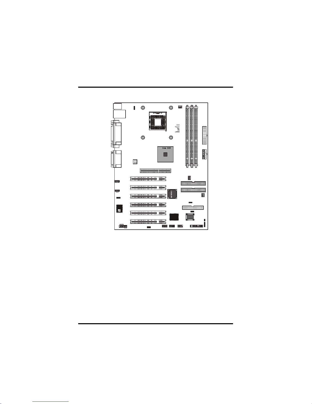
L ayout
i
n
t
e
l
B
I
O
S
C
C
CD-IN
AUDIO
Aux-IN
ATX12v
mPGA478B
CPU
FCPUPS2_SB
AGP
PCI1
PCI2
PCI3
PCI4
PCI5
PCI6
WOL
IR
CMOS
Flash
Fsys
FDD
IDE0
IDE1
Faux
D
DIM
M2DIM
M
3
ATX PWR
AT PWR
SMBUS
C
USB
SMART CARD
Front Pannel Connector
SPDIF
IWILL 6CH bracket
P
4
S
Page 5
5
Chapter 1 Quick Installation
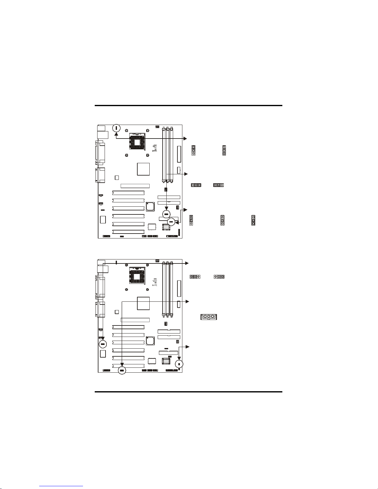
Jumpers/Connectors
PS2_SB
Clear CMOS
Flash Protect jumper
Disabled(Default) Enabled
Clear CMOS
Flashable by H/W Protected by H/WControl by BIOS
(Default)
Normal(Default)
1
1
1
12222331231231233
3
Audio Jumper
Wake-ON-LAN
Case Open
Disabled
PIN Assignment
1: 5VSB
2: GND
3: LAN_Wake
Enabled
(Default)
1 1
1
2 2
2
3 3
3
Page 6
Chapter 1 Quick Installation
6
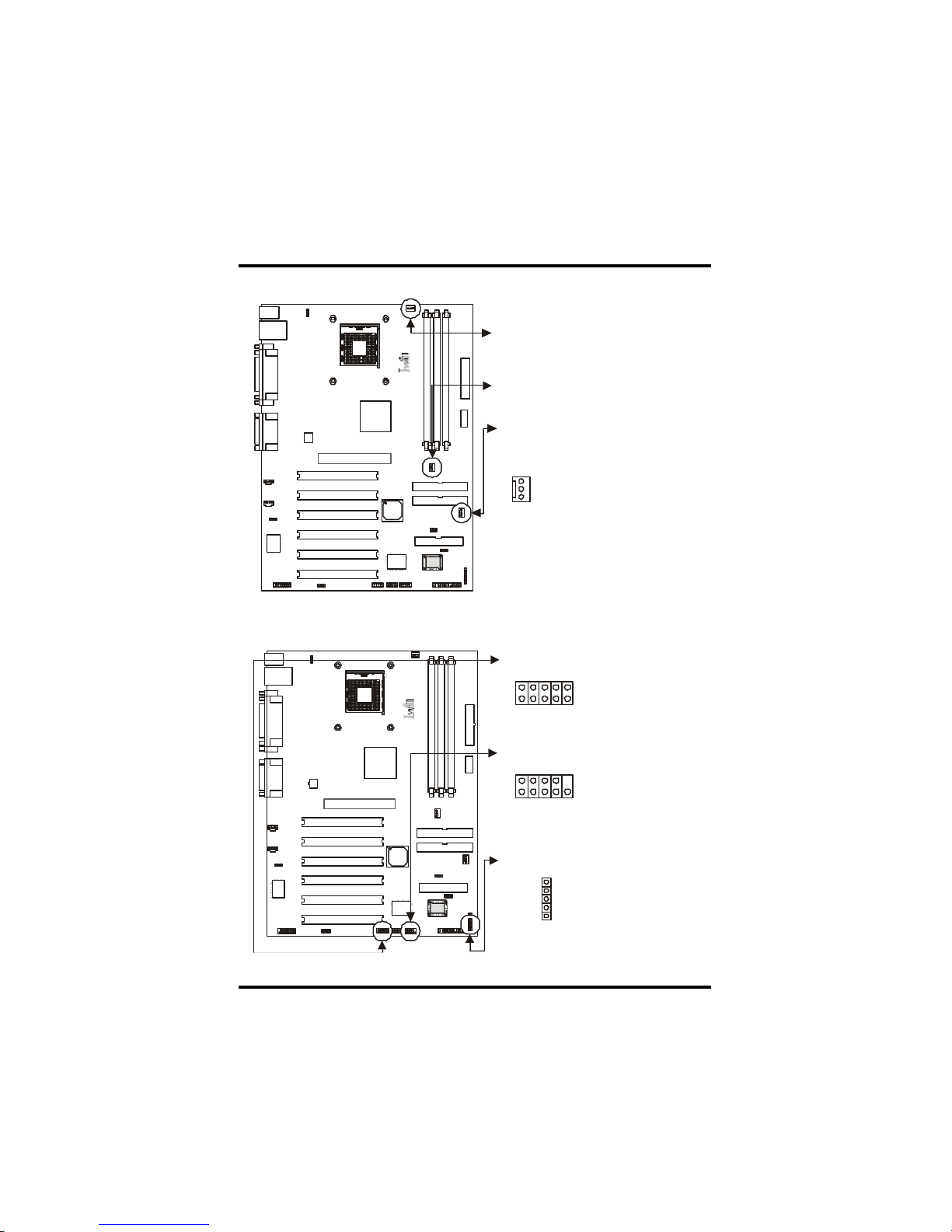
CPU Fan
Auxiliary Fan
System Fan
PIN Assignment
1: GND
2: 12V
3: Sensor
123
Infrared connector (IR)
Internal USB connector
SMBus connector
PIN Assignment
1: SMBUSCLK
2: NC
3: GND
4: SMBDATA
5: VCC
PIN Assignment
1: 5V 6: NC
2: NC 7: CIRRX
3: IRRX 8: 5VSB
4: GND 9: NC
5: IRTX 10: NC
PIN Assignment
1: 5V 6: 5V
2: USBDT2- 7: USBDT33: USBDT2+ 8: USBDT3+
4: GND 9: GND
5: GND 10: NC
12345
1
6 7 8 9
10
2 3 4 5
16789
10
2 3 4 5
Page 7
7
Chapter 1 Quick Installation
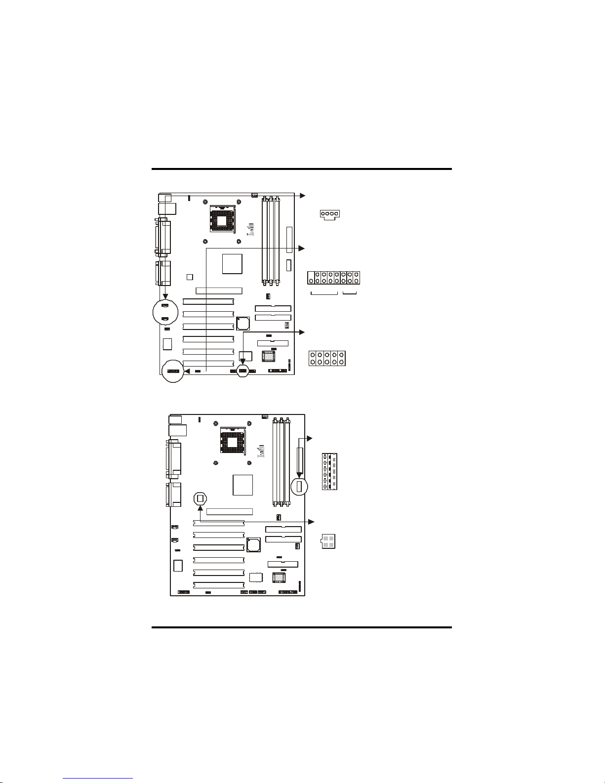
Aux_In/ CD_In Connector
SMART CARD
SPDIF & IWILL 6CH bracket
PIN Assignment
1: +12V 2:NC
3: NC 4: SPDIFO
5: SPDIFI 6: GND
7: NC 8: SPGPIO
9: NC 10: NC
11: BASS 12: XREARR
13: GND 14: GND
15: CENTER 16: XREARL
PIN Assignment
1: Left Channel
2: GND
3: GND
4: Right Channel
PIN Assignment
1: VCC 6: GND
2: SCPWR- 7: SCRST3: NC 8: NC
4: SCIO 9: NC
5: SCCLK 10: SCDSNT
123416789
10
2 3 4 5
SPDIF
6 CH bracket
16789101112131415
16234
5
112233445
6
AT-PWR connector
ATX12V connector
PIN Assignment
1: GND
2: GND
3: GND
4: 3.3V
5: 3.3V
6: 5V
PIN Assignment
1: GND
2: GND
3: 12V
4: 12V
Page 8
Chapter 1 Quick Installation
8
PIN No. Definition PIN No Definition
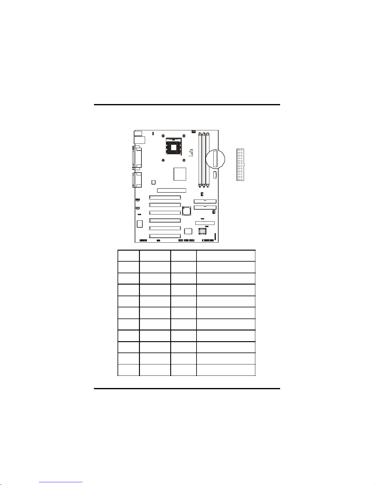
1 +3.3V 11 +3.3V
2 +3.3V 12 -12V
3 Ground 13 Ground
4 +5V 14 Power Supply On
5 Ground 15 Ground
6 +5V 16 Ground
7 Ground 17 Ground
8 Power Good 18 -5V
9 +5V 19 +5V
10 +12V 20 +5V
ATX power connector
11011
20
Page 9
9
Chapter 1 Quick Installation
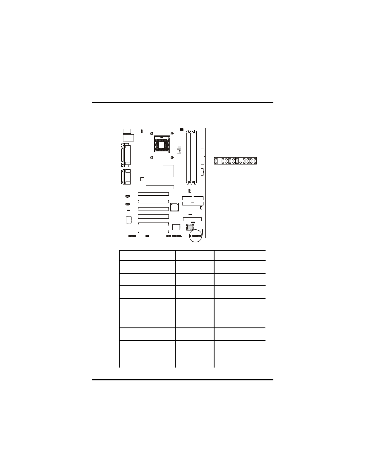
Function PIN NO. Definition
PWR_ON
(Power/Soft_Off)
1,13
ACPI(ACPI LED) 3,4
PIN 3:Anode
PIN 4:Cathode
ALED(IDE LED) 7,8
PIN 7:Anode
PIN 8:Cathode
RST(RESET) 11,12
PIN 11:RST
PIN 12:GND
PLED
(System PowerLED)
15,16,17
PIN 15:VCC
PIN 16:NC
PIN 17:GND
KL
(Keyborard Lock)
18,19
PIN 18:KL
PIN 19:GND
SPKR(Speaker) 21,22,23,24
PIN 21:VCC
PIN 22:NC
PIN 23:NC
PIN 24:SPEAK
(BUZZ)
Front panel connector
12413
12
Page 10
10
Chapter2 Feature
Fea tures
Motherboard Comp onents Placement
i
n
t
e
l
B
I
O
S
C
3
D
X
H
S
P
5
6
C
M
I
8
7
3
8
1234567
8
9
10
11
12
13
14
15
16
17
4
Page 11

11
Chapter2 Feature
[
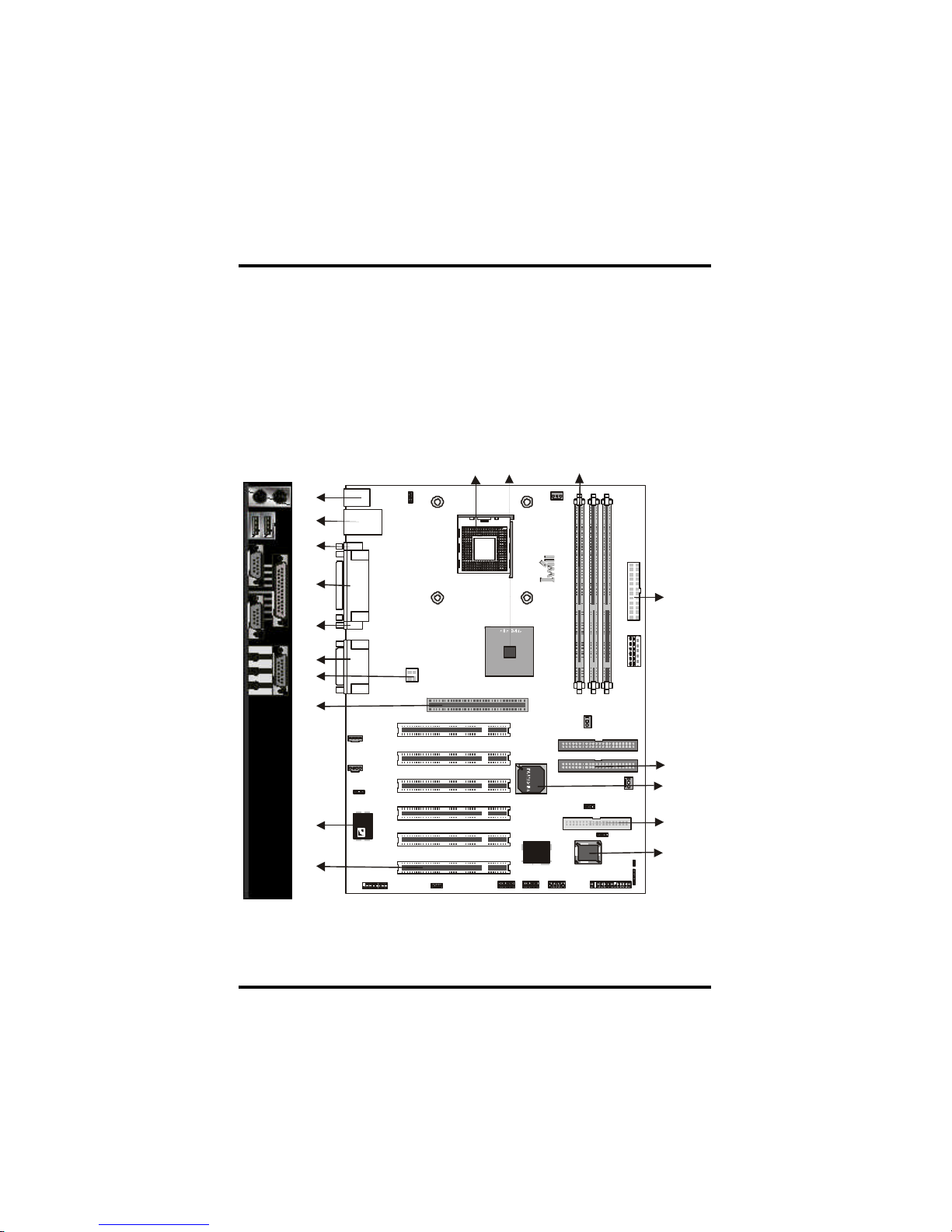
NO. Description
1 CPU Socket (478 Pin)
2 i845 chipset
3 DIMM sockets
4 ATX Power connector/AT Power/ATX 12V
5 FDC connector
6 IDE connector
7 Intel ICH2 chipset
8 FWH chipset for programmable BIOS
9 PCI slots
10 CMI sound chip
11 AGP slot
12 Joystick, Midi Line In / Out, Microphone In
13 Parallel Port
14 COM1
15 COM2
16 USB
17 PS2 Mouse / Keyboard
Page 12
12
Chapter2 Feature
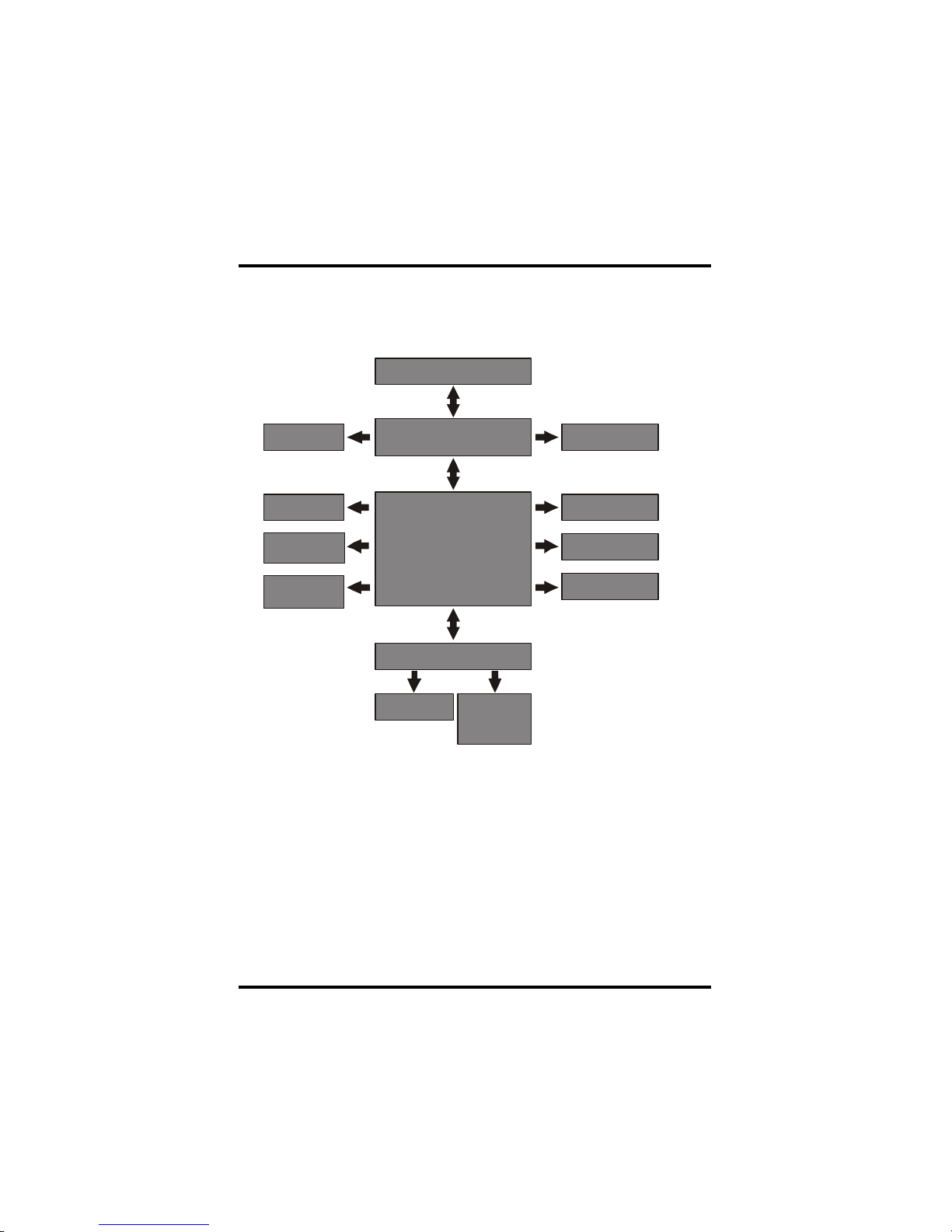
Block Diagram
AGP 4X
SDRAM
IDE Channel x 2
Socket 478 CPU
Super I/O
i845 Chipset
(North Bridge)
ICH2 82801BA
(South Bridge)
PCI x 6
6 Channel sound
H/W Monitoring
Serial Port x 2
Infrared Port
Parallel Port
FDC
2xUSB Ports
Internal USBx2
Keyboard & Mouse
SM Bus
Page 13

13
Chapter2 Feature
Specifications
Processor / (Socket478)
Supports 1 processors
Supports 400M FSB ( Front Side Bus)
Supports Intel Pentium 4 CPU from 1.4 to 1.7 GHz and higher.
CPU Frequency/Voltage Selection
Supports Vcore selection from BIOS
Supports C PU Multiplier selection from BIOS
Supports C PU External Frequency selection f rom BIOS
Memory
Supports PC 100/PC133 SD RAM
Supports E CC DIMMs (Single bit er ror Correction, Multiple bit error
Detection)
Supports 16M /64M/128M/256M/512M DRAM technology
Supports up to 3GB when using 512M technology DR AM
Supports DIMM type 64Mb/128Mb/256Mb Technologies for x8 and x16
DEVICE
Gr aphi cs
Suppo rts AGP 4X1.5V ONLY
General I/O
P CI 2.1/2.2 compliance
Supports 32-bit/33MHz P CI interf ace
Supports LPC interf ace
Suppo rts ATA33/ATA66 /ATA100 IDE inte rface
Supports Floppy interface
Supports 16550A UART interface
Supports EC P/E PP interface
Supports PS2 interface
Supports SIR /FIR /CIR interface
Supports USB interface
Sound support
H W Sound controller on board
Supports CMI8738 H/W 6 Channel and SPDIF
Supports Game/MIDI interface
Supports Win9X/WinNT/Win2000/Linux/N et Ware.
Page 14

14
Chapter2 Feature
Management
Support s voltage monitoring
(+12V/-12V/+5V/-5V/Vcore/Vcore2 /VTT/VIO/Vbat/Vsb)
Supports f an control signal (CPU/AUX/SYS1)
Supports temperature sensor (CP U/AUX/SYS)
Supports Chassis Intrusion
Supports P ower on by LAN/Ext. Modem/Int. Modem /PS2 Keyboard/
P S2 Mouse/RTC/PME
Supports R esum e by LAN/Ext. Modem /Int. Modem/PS2 Keyboard/
P S2 Mouse/RTC/PME
Supports AC PI
Supports AP M
Supports DMI
Supports SMBUS
Suppor ts P nP
Supports BIOS R OM Flash Control
(3-pin jumper provide H/W & S/W protection)
Supports “AC- Loss Recovery”
S upports Manually Assign PCI IRQ
Suppor ts PS2 mouse and P S2 keyboard auto swapping
Power requirement
Onboard DC /DC switching voltage regulator supports VIO up to 10A
current
D escrete voltage regulator for AGP port
Supports adjustable VIO (Normal/Increase 5%/Increase 10%,
Normal=3.4V, jum per/BIOS)
Supports 150A//us Icc slew rate
Expansion Slot, Sockets and Connectors
One Socket478 socket
Three DIMM sockets
On e AGP 1.5V AGP slots
SIX 32bit/33MH z Bus Master PCI slots
Two ID E connectors
One FDC connector
One Intern al USBx2 connectors
One ATX 20-pin power connector
One ATX 4-pin power connector (ATX 12v for Vcore)
One AT 6-pin power connector
Page 15
15
Chapter 3 Hardware Setup
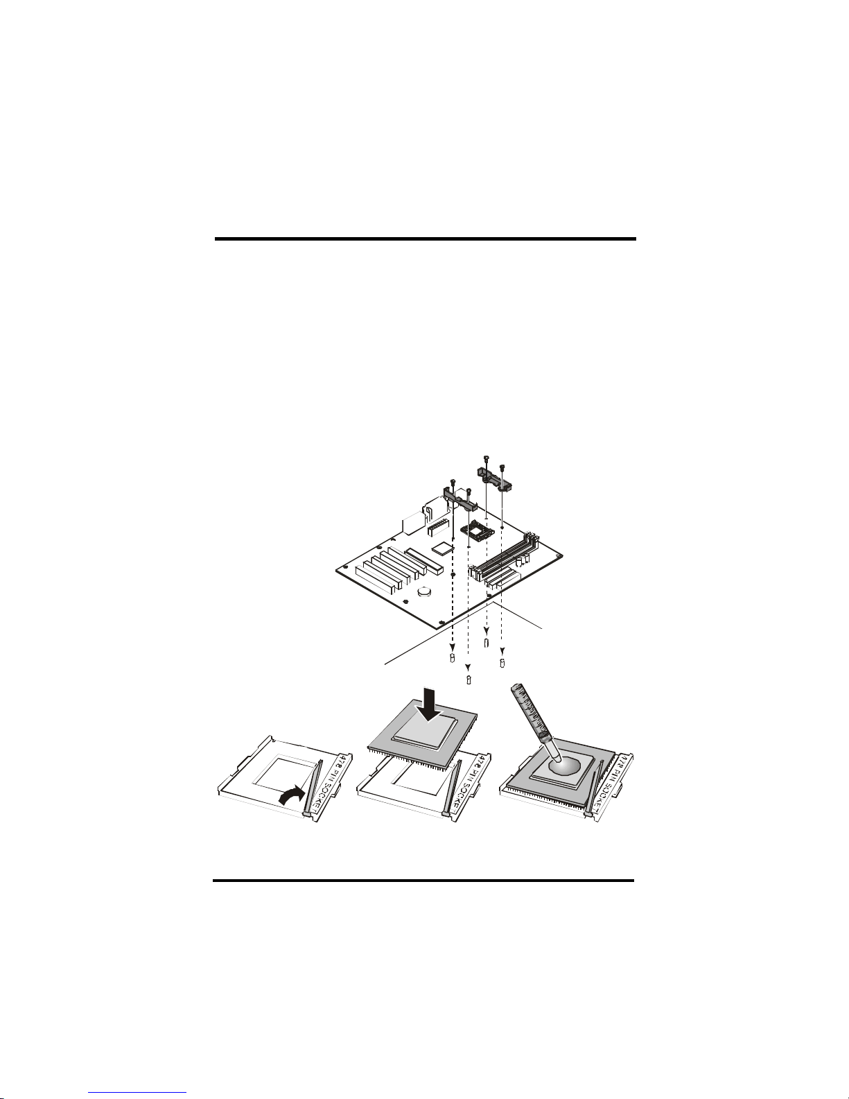
Intel Pentiu m 4 Processor Installation Procedure
Make sur e your chassis supports the Intel Pentium 4 processor.
(A) Insert four standoffs into the four holes below the processor
s ocket.
(B) Install the motherboard into the chassis.
(C ) Secure the retention m echanism s into the f our standoffs
(D ) Open the socket 478 handle
(E ) Install the Pentium 4 processor and close the socket handle
(F) Apply some of the thermal cream to the top of the Pentium 4
Ha rdware Setup
Open the socket handle
Install the processor Apply some cream
Page 16
16
Chapter 3 Hardware Setup
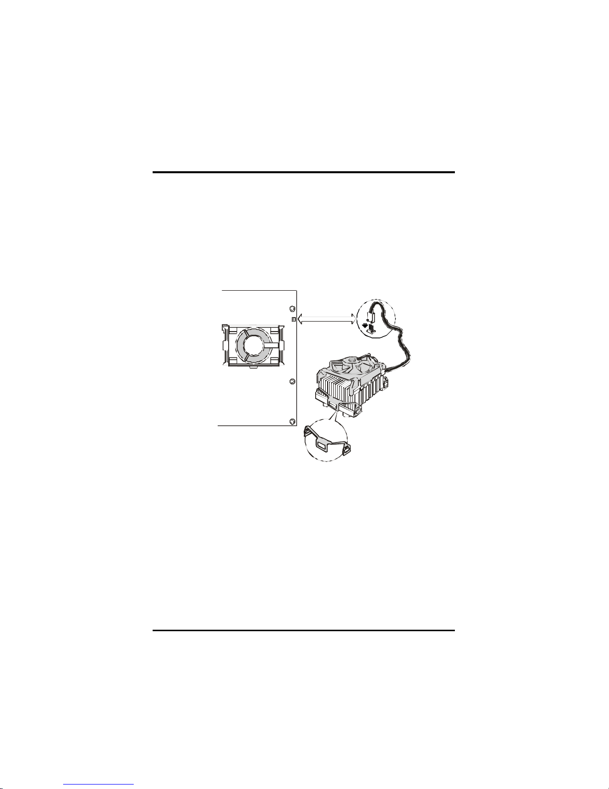
CPU Cooler Installation Notes
Align the C ooler base with the retention m echanism s and place it on the
C PU. Starting with the center tab, install the clips to the retention
mechanism tabs. Connect the processor fan cable connector to the
motherboard header.
Page 17
17
Chapter 3 Hardware Setup
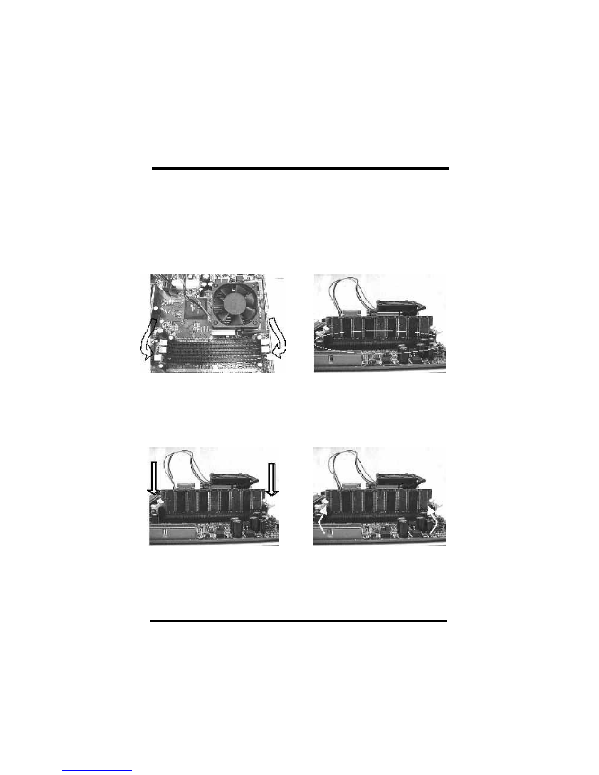
Install Memory Modules
The motherboard has three Memory sckets and supports memory size up
to 3 GB.
Step1: Step2:
Open latches of DIMM socket. Proofread the RAM module to the
DIMM Socket.
Step3: Step4:
Insert the RAM module into the DIMM
socket.
Press the latches into the notches of the
RAM module.
Page 18
18
Chapter 3 Hardware Setup
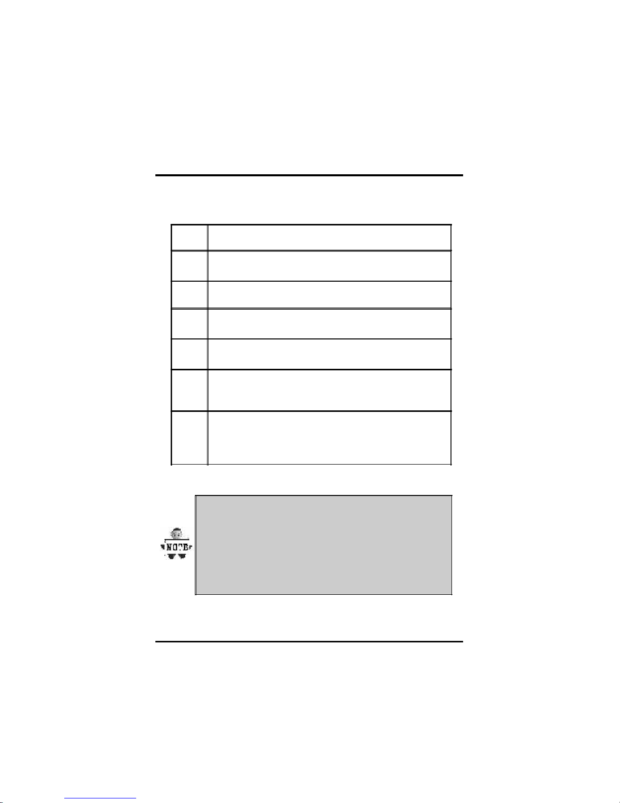
ATX Power Supply Connector
STEP Description
1
After all connections are made, close the system case
over.
2 Be sure that all switches are off.
3
Connect the power cord into the power suppply located
on the back of your system case.
4
Connect the power cord a power outlet that is equipped
with a surge protector.
5
Many of the power supply support 110V/220V by a
switch setting. Switch your power supply to the correct
supply voltage.
6
Turn on your system in the following order
a. The monitor
b. The external devices.
c. The computer system.
Power on procedures
The power LED on the front panel of the chassis will
light. After few seconds, the system will then run poweron tests. Some additional messages will appear on the
screen during the test. If you do not see anything within
30 seconds from the time you turn on the power, the
system may have failed a power-on test. Recheck the
jumper settings and connections or call your retailer for
assistance.
Page 19

19
Chapter 3 Hardware Setup
Function color Description
PS2/Mouse Green
This connector can be used to support
a PS/2 mouse
PS2/
keyboard
Purple
This connector can be used to support
a PS/2 keyboard.
Universal
Serial Bus
Black
This motherboard has two USB ports,
any USB-compatible peripherals
and/or hub can be connected into
either USB port.
Serial port Teal
One serial port is ready for a modem
or other serial devices
Parallel
port
Burgundy
This connector is used for printers, or
other parallel devices.
Joystick,
Midi and
Audio Port
Gold
You may connect joysticks or game
pads to this connector for playing
games, or connect MIDI devices for
playing / editing professional audio.
Line Out (Lime color) can be
connected to headphones or powered
speakers. Line In (Light Blue color)
allows audio sources to be recorded
by your computer or played through
the Line Out connector. Mic (Pink
color) allows microphones to be
connected for inputting voice.
Back Panel
Page 20

20
Chapter 4 BIOS Setup
BIOS Setup
Upgrade BIOS
The BIOS can be upgraded from a diskette with the Award Flash
utility — AWDFLASH .EXE. The BIOS image file, and update utility
are available from IWILL’s WEB site: s upport.iwil l.net
Enter BIOS setup program
Power-on the system by either pressing the P ower-On button, or
by using any of the power-on features provided by the
motherboard. Then, press the <D el> key after the Power-On Self
Test (P OST), and before the scanning of IDE devices. Sim ply look
f or the message “P ress DEL to enter SETUP” displayed at the
bottom of the screen dur ing the boot up process. If the message
disappears bef ore you’ve had a chance to respond, you can restart
the system byturning of f the system power then turn it on again,
orP ressing the “R ESET” button on the system case, or
P ressing <Ctrl>, <Alt> and <Del> keys sim ultaneously.
Generally, the BIOS default settings have been carefully
chosen by IWILL's Engineers provide the absolute
maximum performance and reliability. It is very
dangerous to change any setting without full
understanding. We strongly recommend that you.
DO NOT update BIOS if the system works perfectly.
DO NOT change any setting unless you fully
understand what it means.
BIO S Setup
Page 21

21
Chapter 4 BIOS Setup
Us ing BIOS setup program
?Up Move to the previous f ield
?D own Move to the next field
?Lef t Move to the field on the left hand side
?R ight Move to the field on the right hand side
<Esc> Quit from setup program without saving changes,or
E xit from current m enu page and return to m ain m enu page
<P gUp> or <+> Select the previous value for a field
<P gDn> or <-> Select the next value for a field
<F1> General Help
<F2> Item Help
<F5> P revious Values
<F6> Fail-Safe D efaults
<F7> Optimized D efaults
<F10> Save the current value and exit setup program
If the system is no longer able to boot after changing the settings, the
only way to recover it is to clear the data stored in R TC CMOS. To reset
the R TC CMOS data, take the JP1 jum per cap off pins 1-2, place onto
pins 2-3, and then place back onto pins 1-2 again. This will return the
R TC to the default setting. Then, get into the BIOS setup program ,
choose Load Fail-Safe D efaults ; Load Optimized Defaults, and select the
original manufacturer default settings in your C MOS.
Page 22
22
Chapter 4 BIOS Setup
Main Menu
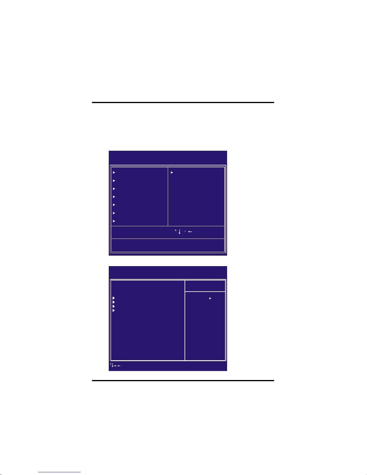
The main m enu allows you to select from several setup pages. U se the
arrow keys to select among these pages and press <E nter> key to enter
the sub- menu. A brief description of each highlighted selection appears
at the bottom of the screen.
Stardard CMOS features
CMOS Setup Utility-Copyright(c) 1984-2001 Award Software
Standard CMOS Features
Advanced BIOS Features
Advanced Chipset Features
Integrated Peripherals
Power Management Setup
PnP/PCI Configurations
PC Health Status
ESC: Quit
F10: Save & Exit Setup
Time, Date Hard Disk Type...
IWILL Smart Setting
Load Fail-Safe Defaults
Load Optimized Defaults
Set Supervisor Password
Set User Password
Save & Exit Setup
Exit Without Saving
: Select Item
CMOS Setup Utility-Copyright(c) 1984-2001 Award Software
Standard CMOS Features
Date (mm:dd:yy)
Time (hh:mm:ss)
IDE Primary Master
IDE Primary Slave
IDE Secondary Master
IDE Secondary Slave
Drive A
Drive B
Floppy 3 Mode Support
Video
Halt On
Base Memory
Extended Memory
Total Memory
Mon, Jun 18 2001
15:17:48
[None]
None]
None]
None]
1.44M,3.5i n.]
[None]
[Disabled]
EGA/VGA]
All Errors]
[
[
[
[
[
[
640k
523264K
524288K
Item Help
Menu Level
Change the day, month,
year and century
: Move Enter: Select +/-/PU/PD: Value F10: Save ESC: Exit F1: General Help
F5: Previous Values F6: Fail-Safe Defaults F7: Optimized Defaults
Page 23

23
Chapter 4 BIOS Setup
Time
This f ield specifies the current time. The time format is <hour>,
<minute>, and <second>. The time is calculated based on the
24-hour (military-time) clock.
IDE Primary Master / Primary Slave / Secondary
Mas ter / Secondary Slave
P ress “E nter” to enter next page for detail hard drive setting.
IDE HDD Auto-Detection
Auto-Detect the H DDs Capacity, and its parameters, ex:
C ylinder, Head and Sector.
IDE Primary Master / Primary Slave / Secondary Master
/ Seconda ry Slave
This f ield specifies type of drive that corresponds to the
drive installed in your system. If you select U ser, please
specif y the correct number of Cylinders, Heads, and
Sect ors.
Manual
Selecting anual lets you set the remaining fields
on this screen. Selects the type of fixed disk.
Auto
(Default Vaule)
BIOS automatically fills in the values for the
cylinders, heads and sectors fields.
None Any Disk Drives are attached
C apacity Auto Display your disk drive size
Access MODE
This field specifies the IDE translation mode.
NORMAL Specifies traditional CHS addressing mode.
LARGE Specifies extended CHS translation mode
LBA Specifies LBA translation mode.
AUTO
(Default Vaule)
BIOS specifies translation method
automatically.
Date
This f ield specifies the current date. The date format is <month>,
<day>, and <year>.
Page 24

24
Chapter 4 BIOS Setup
C ylinders
Set the number of cylinders for this hard disk.
Heads
Set the number of read/write heads
P recomp
Setting a value of 65535 means no hard disk
Sectors
Set the number of sectors per track
Driv e A / Drive B
This f ield specifies the traditional type of floppy drives.
None
(*Drive B default)
Any Floppy drive is connected
360K, 5.25 in.
Specifies extended CHS translation
mode
1.2M, 5.25 in. A 1.2M floppy drive is connected
720K, 3.5 in. A 720K floppy drive is connected.
1.44M, 3.5 in.
(*Drive A default)
A 1.44M floppy drive is connected
2.88M, 3.5 in. A 2.88M floppy drive is connected
Flopp y 3 Mode Support
3 Mode f loppy drive is a type of 3.5-inch drive used by NEC PC98
computers. It supports both 1.2M and 1.44M formats using the
same drive. This field specifies which drive supports 3 Mode.
When a f loppy drive is specified to support 3 Mode, the
respective drive setting in “Drive A / Drive B” f ield will be invalid.
Disabled
(Default Value)
No 3 Mode drive is connectedd
Drive A A 3 Mode drive is connected as drive A
Drive B A 3 Mode drive is connected as drive B
Both Both drive A and drive B are 3 Mode drives
Page 25

25
Chapter 4 BIOS Setup
Video
EGA/VGA
(Default Value)
Specifies EGA or VGA adapterd
CGA 40 Specifies CGA adapter with 40 column mode
CGA 80 Specifies CGA adapter with 80 column mode
MONO Specifies Monochrome adapter
Halt On
All Errors
(Default Value)
Each time the BIOS detects a non-fatal error,
the system will stop and display an error
message
No Errors
The system will stop for any errors that are
detected
All, But Keyboard
The system will stop for any errors except
keyboard error
All, But Diskette
The system will stop for any errors except
diskette error
All, But Disk/Key
The system will stop for any errors except
diskette and key board errors
Base Memory
The P OST (Power-On Self Test) determ ines the amount of base
(conventional) m em ory installed in the system. The value of the
base mem ory is typically 640K. This f ield has no options.
Extended Memory
The BIOS determines how much extended memory is present
during the P OST. This is the amount of m em ory located above
1MB in the processor’s m emory address m ap. This field has no
options.
Total Memory
D isplays the total m em ory available in the system
Page 26
26
Chapter 4 BIOS Setup
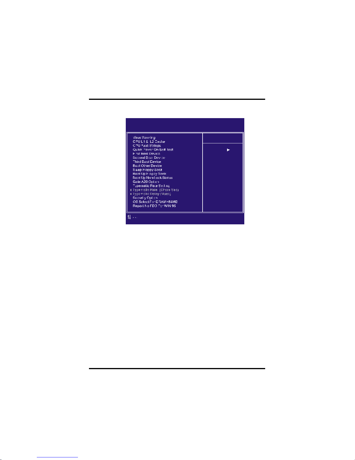
Advanced BIOS Features
This f ield configures the CPU L1 & L2 cache.
When this f unction is enabled and any attempt to write data into
this area is made, the BIOS monitor will display a warning
message on screen and beep. If you want to run an anti-virus
program, we recommend you that it will disable and appear the
Virus Warning function beforehand.
CMOS Setup Utility-Copyright(c) 1984-2001 Award Software
Advanced BIOS Features
[Disabled]
[Enabled]
[Enabled]
[Enabled]
[Floppy]
[HDD-0]
[SCSI]
[Enabled]
[Enabled]
[On]
[Fast]
[Disabled]
[Setup]
[Non-OS2]
[No]
[Disabled]
6
250
Item Help
Menu Level
Allows you to choose
the VIRUS warning
feature for IDE Hard
Disk boot sector
protection. If this
function is enabled
and someone attempt to
write data into this
area , BIOS will show
a warning message on
screen and alarm beep
: Move Enter: Select +/-/PU/PD: Value F10: Save ESC: Exit F1: General Help
F5: Previous Values F6: Fail-Safe Defaults F7: Optimized Defaults
[Enabled, Disabled (Default Value)]
[E nabled(Default Value),Disabled]
CP U Fast-Strings
E nabled is best for performance.
[E nabled(Default Value), Disabled]
Quick Power On Self Test
This field allows the system to skip certain tests while booting.
This will decrease the time needed to boot the system.
[E nable(Default Value), Disabled]
CPU L1& L2 Cache
Virus Warning
Page 27

27
Chapter 4 BIOS Setup
First / Secondary / Third / Boot Other Device
The BIOS attempts to load the operating system from the devices
in the sequence selected in these items.
[Floppy, LS120, H DD-0, SC SI, CDR OM, HDD-1, HDD-2,
H DD-3, ZIP100, LAN, Disabled]
Swap Floppy Drive
When enabled, f loppy drives A and B will be exchanged without
the user physically changing the connection on the cable.
[E nable, Disabled(Default Value)]
Boot Up Floppy Seek
Seeks disk drives during boot up. D isabling speeds boot up.
[E nabled, Disabled (Default Value)]
Boot Up NumLock Status
[ON (Default Value),Off ]
Gate A20 Option
This f ield configures how the gate A20 is handled. The gate A20 is
a device used to address memory above 1 MB. At first, the gate
A20 was handled from a pin on the keyboard. While some
keyboar ds still provide this support, it is more comm on, and m uch
f aster, for modern system chipsets to provide support for gate A20.
[Fast(Default Vaule):GateA20 signal supported by core logic]
[N orm al: GateA20 signal supported by keyboard controller].
Typematic Rate Setting
This f ield determines if the typem atic rate is to be used. When
enabled, the BIOS will report (after a moment) that the key has
been depressed repeatedly. When disabled, the BIOS will report
only once if a key is held down continuously. This feature is used
to accelerate cursor movements using the arrow keys.
[E nable, Disabled(Default Value)]
This field determines the configuration of the numeric keypad after
system boot up. If On, the keypad uses numbers keys. If Off,the
keypad uses arrow keys.
Page 28

28
Chapter 4 BIOS Setup
Typematic Rate (Chars/Sec)
When Typematic R ate Setting enabled, this field specifies how
many characters will be displayed in one second when a key is
held down continuously.
[6(
Default Value)8,10,12,15 ,20,24,30]]
Typematic Delay (Ms ec)
When enabled, typematic delay allows you to select the time delay
between when the key is first pressed and when the acceleration
begins.
[250m sec(Default Value)500m sec,750m sec,1000msec]
Security Option
This f ield configures how the system security is handled. It works
conjunction with SE TTING SUPERVISOR / USER PASSWORD
page to control the security level of the system.
[Setup(Default Value):System needs a password to enter BIOS
setup program.]
[System:System needs a password to boot.]
OS Select for DRAM >64MB
When enabled, this field allows you to access the memory that is
over 64MB under OS/2.
[OS2, No n-OS2(Default Value)]
Report No F DD For WIN 95
[YES, NO(Default Value)]
For a floppy diskless system that runs Windows 95, this f ield should
be set tp Yes.
Page 29

29
Chapter 4 BIOS Setup
This setup page is used to specify advanced features available through
the chipset. The default settings have been chosen carefully for most
operating conditions. DO N OT change the value of any field in this setup
page without full understanding.
The f irst chipset settings deal with CP U access to dynam ic random
access memory (DRAM). The default timings have been carefully
chosen and should only be altered if data is being lost. Such a
scenario might well occur if your system had m ixed speed DRAM
chips installed. Longer delays might result, however this
preserves the integrity of the data held in the slower memory
chips.
DRAM Timing Selectable
Selects Whether DRAM Timing is controlled by the SPD. It is serial
presence detect.
[By SPD (Defa ult Value), By U ser]
CAS Latency Time
This contr ols the number of clocks between the SDRAM read
command and the time that the data actually becomes available.
[2, 3(Default Value)]
CMOS Setup Utility-Copyright(c) 1984-2001 Award Software
Advanced Chipset Features
DRAM Timing Selectable
x CAS Latency Time
x Active to Precharge Delay
x DRAM RAS# to CAS# Delay
x DRAM RAS# Precharge
DRAM Data Integrity Mode
System BIOS Cacheable
Video BIOS Cacheable
Video RAM Cacheable
Delayed Transaction
AGP A perture Size (MB)
Delay Prior to Thermal
[By SPD]
3
6
3
3
Non-ECC
[Enabled]
[Disabled]
[Disabled]
[Enabled]
[64]
[16 Min]
Item Help
Menu Level
: Move Enter: Select +/-/PU/PD: Value F10: Save ESC: Exit F1: General Help
F5: Previous Values F6: Fail-Safe Defaults F7: Optimized Defaults
DRAM Settings
Advanced Chipset F eatures
Page 30

30
Chapter 4 BIOS Setup
Delayed Transaction
When enabled, the south bridge ICH2 will supports the Delayed
Transaction mechanism when it is the target of a P CI transaction.
[E nable(Default Value),Disabled]
AGP Aperture Size (MB)
This f ield configures the main mem ory size for AGP graphics data
used.
[4MB, 8 MB, 16MB, 32MB,64MB(Default Value), 128MB, 256MB]
DRAM RAS# Precharge
If an insufficient number of cycles is allowed for the RAS to
accumulate its charge before DR AM refresh, the ref resh m ay be
incomplete and the D RAM m ay fail to retain data. This controls the
idle(delay) clocks after issueing a prechange command to the
SD R AM.
[2,3(Default Value)]
Sys tem BIOS Cacheable
When enabled, accesses to the system BIOS will be cached.
[E nable(Default Value),Disabled]
Video BIOS Cacheable
When enabled, access to the video BIOS will be cached.
[E nable, Disabled(Default Value)]
Video RAM Cacheable
When Disabled, access to the video memory located at A0000H to
BFFFFH will be cached.
[E nabled, Disabled (Default Value)]
DRAM RAS# to CAS# Delay
This controls the num ber of clocks between the SDRAM active
command and the read / write com m and.
[2,3(Default Value)]
Page 31
31
Chapter 4 BIOS Setup
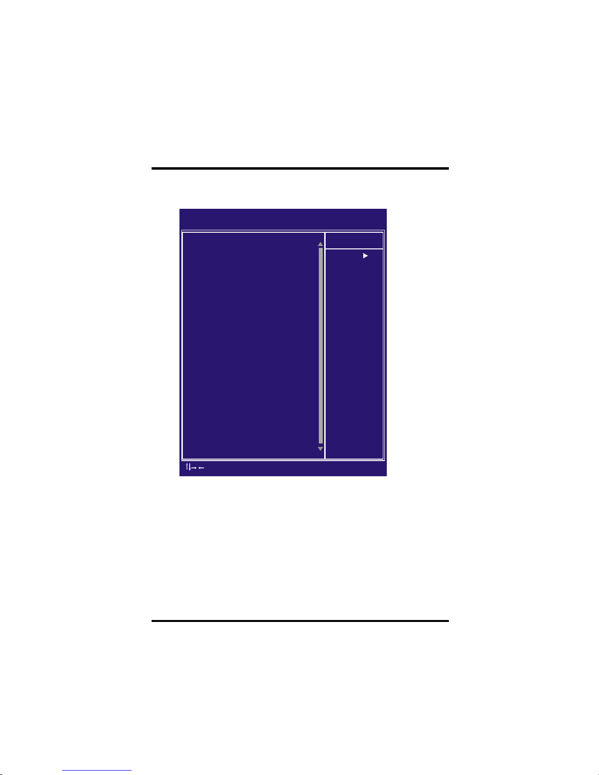
Integrated Peripherals
CMOS Setup Utility-Copyright(c) 1984-2001 Award Software
Integrated Peripherals
On-Chip Primary PCI IDE
On-Chip Secondary PCI IDE
IDE Primary Master PIO
IDE Primary Slave PIO
IDE Secondary Master PIO
IDE Secondary Slave PIO
IDE Primary Master UDMA
IDE Primary Slave UDMA
IDE Secondary Master UDMA
IDE Secondary Slave UDMA
USBController
USB Keyboard Support
Init Display First
IDE HDD Block Mode
POWER ON Function
x kB Power ON Password
x Hot Key Power ON
Onboard FDC Controller
Onboard Serial Port 1
Onboard Serial Port 2
UART Mode Select
x RxD , TxD Active
x IR Transmission Delay
x UR2 Duplex Mode
x Use IR Pins
Onboard Parallel Port
Parallel Port Mode
x EPP Mode Select
x ECP Mode Use DMA
PWRON After PWR-Fail
SCR Port Address
x SCR Port IRQ
[Enabled]
[Enabled]
[Auto]
[Auto]
[Auto]
[Auto]
[Auto]
[Auto]
[Auto]
[Auto]
[Disabled]
[Disabled]
[AGP]
[Enabled]
[BUTTON ONLY]
Enter
Ctrl-F1
[Enabled]
[3F8/IRQ4]
[2F8/IRQ3]
Normal]
Hi , Lo
Enabled
Half
IR-Rx2Tx2
[378/IRQ7]
[SPP]
EPP1.9
3
[Off]
[Disabled]
11
Item Help
Menu Level
: Move Enter: Select +/-/PU/PD: Value F10: Save ESC: Exit F1: General Help
F5: Previous Values F6: Fail-Safe Defaults F7: Optimized Defaults
Page 32

32
Chapter 4 BIOS Setup
Auto(Default Value)
Mode 0
Mode 1
Mode 2
Mode 3
Mode 4
Negotiated with device automatically
Use Mode 0 timing to access device
Use Mode 1 timing to access device
Use Mode 2 timing to access device
Use Mode 3 timing to access device
Use Mode 4 timing to access device
IDE Pr imary Master / Slave UDMA
IDE Secondary Master / Slave UDMA
If you select Au to, the IDE controller uses Ultra DMA 33/66 Mode
to access U ltra DMA-capable IDE devices. Depend on the resent
of negociation with your HDD. The maxim um transfer rate of Ultra
D MA 66 Mode is 66.6 MB/sec.
[Auto(Default Value),Disabled]
USB Controller
Select D isabled if your system contains USB peripherals.
[E nable, Disabled(Default Value)]
USB Keyboard Support
Select E nabled if you want to use USB keyboard under DOS
[E nable, Disabled(Default Value)]
Init Display First
This item allows you to decide which slot to activate first, either
P CI slot or AGP slot.
[P CI Slot,AGP(Default Value)]
PIO Mode 0
PIO Mode 1
PIO Mode 2
PIO Mode 3
PIO Mode 4
3.3 MB/sec
5.2 MB/sec
8.3 MB/sec
11 MB/sec
16.6 MB/sec
IDE Primary Master / Slave PIO
IDE Secondary Master / Slave PIO
These fields configure the P IO (P rogramm able Input Output) transfer
mode for each ID E devices. The m axim um transf er rates of each P IO
mode are listing as follow:
This field enables or disables the onboard ID E contr oller.
[E nable(Default Value), Disabled]
On-Chip primary/Secondary PCI IDE
Page 33

33
Chapter 4 BIOS Setup
The P ower-On button will not function in this m ode.
Password
You can assign a password string
through KB Power-On Pass word field.
Hot KEY
You can assign a hot key through the Hot Key
Power-On field.Pressing this hot key will poweron your system.
Mouse/
Password
Double-Clicking the mouse button or typing the KB
power-on password will automatically power-on
your systrem
Mouse/Hot KEY
Double-Clicking the mouse button or typing the KB
hot-key will power-on your systrem
BUTTON ONLY
(Default Value)
Simply power-on your system by pressing the
Power-On button on the front panel of your PC
case
Keyboard 98
Enables Keyboard 98 function.This founction is
good only for users of Keyboard 98.
KB Pow er ON Password
If you wish to use this function, bring the cursor to the
f ield written Enter, then press <Enter>. The computer will
display the message, E nter Password”. Type your
password and press <Enter>. After the m essage Confirm
P assword is displayed, re-type your password. The KB
P ower-On function will be in eff ect after you save and exit
set up.
To disable a password, bring the cursor to the Enter” f ield
again, then press <Enter>. The computer will display the
message, E nter Password Press <Enter>. A message will
conf irm that the password is disabled.
Power-On Function
This f ield configures the P ower-On mode of the system.
IDE H DD Block Mode
When enabled, the IDE controller will use the faster block m ode to
access devices.
[E nable(Default Value), Disabled]
Page 34

34
Chapter 4 BIOS Setup
This field enables or disables the onboard floppy controller.
[E nable(Default Value),Disabled]
Onboard Serial Port 1 / 2
These fields conf igure the onboard serial ports. There are several
port addresses and IR Q channels to select from .
UART Mode Select
When s ettin g the field to either IrD A or ASKIR, you m ust
select t he active level of receiving and transmission signal.
[Hi,Lo(
Default Value)/Lo,H i/Lo,Lo/Hi,Hi]
IR Transmission delay for Ir DA and ASKIR functions
3F8 / IRQ 4
(Default Vaule)
Port address 3F8h, IRQ 4
2F8 / IRQ 3
(Default Vaule)
Port address 2F8h, IRQ 3
3E8 / IRQ 4 Port address 3E8h, IRQ 4
2E8 / IRQ 3 Port address 2E8h, IRQ 3
Auto BIOS assigns port address and IRQ
channel automatically.
Disabled. Disables serial port
[IrD A, ASKIR, Norm al(Default Value)]
Wh en setti ng the fiel d to either IrDA o r ASKIR , you m ust sele ct
whether or not you require a delay between IR transm issions.
Hot Key Pow er-On
This field specifies key selection for the Keyboard-Power
On hot key.
[C trl-F1,Ctrl-F2,C trl-F3,Ctrl -F4,Ctrl-F5,C trl-F6,Ctrl-F7,C trl-
F8,C trl-F9, Ctrl-F10,Ctrl-F11,C trl-F12]
Onboard F DC Controller
RxD, TxD Active for IrDA a nd ASKI R functions
[E nabledl(Default Value), Disabled]
Page 35

35
Chapter 4 BIOS Setup
Onboard Parallel Port
This field configures the onboard parallel port. There are several port
addresses and IR Q channels to select f rom .
378 / IRQ 7
(Default Value)
Port address 378h, IRQ 7
278 / IRQ 5 Port address 278h, IRQ 5
3BC / IRQ 7 Port address 3BCh, IRQ 7
Disabled
Disables parallel port
Parallel Port Mode
This f ield configures the operating mode of an onboard parallel
port. Ensure you know the specifications of your parallel port
devices before selecting field.
[SP P(Default Value),EPP,ECP EC P +EPP]
EPP Mode Select
When the P arallel Port Mode f ield is configured as EP P,
E CP+EPP mode, the EPP version needs to be specified. Please
ref er to ypur peripheral document before selecting field.
[E PP1.7:Use EPP 1.7 protocol]
[E PP1.9 (Default Value):Use EPP 1.9protocol]
ECP Mode Use DMA
When the P arallel Port Mode f ield is configured as EC P,
E CP+EPP m ode, it needs a DMA channel for data transfer . This
f ield specifies the DMA channel for ECP par allel port use.
[1:U se DMA channel 1]
[3(Default Value):U se DMA channel1]
UR2 Duplex M ode
[Full,H alf(Default Value)]
Use IR Pins
[R xD2,TxD2,IR-Rx2Tx2(Default Value)]
Page 36
36
Chapter 4 BIOS Setup
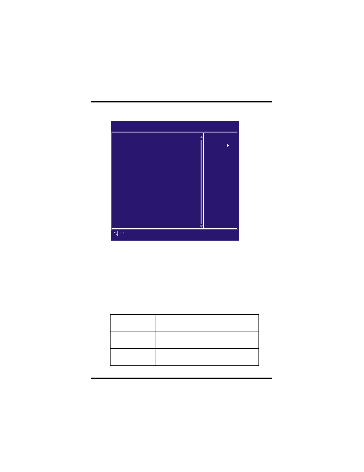
This f eature allows the user to select the default parameters for
the power-saving m ode.
Min saving
When idle for one hour, the system
entersuspend mode.
Max Saving
When idle for fifteen minutes, the system
enters suspend mode.
User Define
(Default Vaule)
User can specify the time the system
enters suspend mode.
E ach power-saving mode has a respective tim er. The value of
the tim er can be assigned or reloaded and it will count down to
zero. When the tim er equals to zero, the system will be forced
into the related suspend or power-saving mode. If any predefined
signal or event is detected during the timer counting period, the
timer restarts autom atically.
Power Management Setup
CMOS Setup Utility-Copyright(c) 1984-2001 Award Software
Power Management Setup
Power Management
Video Off Method
Video Off In Suspend
Suspend Type
MODEM Use IRQ
APM Suspend Timer
APM HDD Power Down Timer
PWR-OFF Mode by PWR-BTTN
Wake Up by PCI card
Wake Up by Ring/LAN
CPU THRM-Throttling
PWROn/Resume by Alarm
x
x
**Reset APM Timer Events**
Primary IDE 0
Date (of Month) Alarm
Time (hh:mm:ss) Alarm
Primary IDE 1
Secondary IDE 0
Secondary IDE 1
FDD, COM, LPT Port
PCI IRQ#
[User Define]
[V /H SYNC+Blank]
[Yes]
[Stop Grant]
[3 ]
[Disabled]
[Disabled]
[Instant-Off]
[Disabled]
[Disabled]
[62.5% ]
[Disabled]
0
0 :0 : 0
[Disabled]
[Disabled]
[Disabled]
[Disabled]
[Disabled]
[Disabled]
Item Help
Menu Level
: Move Enter: Select +/-/PU/PD: Value F10: Save ESC: Exit F1: General Help
F5: Previous Values F6: Fail-Safe Defaults F7: Optimized Defaults
Pow er Management
Page 37

37
Chapter 4 BIOS Setup
Video off Method
V/H SYNC+Blank
(Default Vaule)
Turn off the vertical and horizontal
synchronization ports and write blanks
to the video buffer.
Blank Screen Writes blanks to the video buffer only.
DPMS
Initial display power management
signaling with DPMS.
This determines the manner in which the monitor is blanked.
[N O,Yes(Default Value)]
Sus pend Type
Select the Suspend Type.
[P wrOn Suspend, Stop Grant (Default Value)]
MODEM Us e IRQ
This field specifies the time the system enters power-saving mode.
It is available only when the Power Managem ent f ield is set to
U ser Define.
[1Min, 2Min, 4M in, 8Min, 12Min, 20Min, 30Min , 40Min, 1Hour,
D isabled(Default Value)]
APM HDD Power Down Timer
This field specifies the time the system enters HD D power down.
It is available only when the Power Managem ent f ield is set to
U ser Define.
[1Min, 2Min, 3Min, 4Min, 5Min, 6Min, 7Min, 8Min, 9Min,10Min,
11Min, 12Min, 13Min, 14Min, 15Min, Disabled(Default Value)]
This f ield specifies the function of power button.
seconds, the system turns off.]
PWR-O ff Mode by P WR-BTTN
[Instant-Of f(Default Value):When power button pressed, the system
turns off immediately.]
[D elav 4 Sec: After the power button has been pressed andheld for four
This determines the IR Q in which the MODE M can use.
[3(
Default Value),4,5 ,7,9,10,11,NA]
APM Sus pend Timer
Video Off In Suspend
Page 38

38
Chapter 4 BIOS Setup
Wake up by PCI card
[E nabled, Disabled(Default Value)]
Wake up by RING/LAN
When Wake up by LAN f unction is enabled, the PC can power-on
or “wake up” through LAN (Local Area Network). When Wake up
by RIN G function is enabled, the PC can power-on through an
external modem connected to your P C.
87.5%
Keep 87.5% of CPUs full speed performance
75.0%
Keep 75.0% of CPUs full speed performance
62.5%
(Default Vaule)
Keep 62.5% of CPUs full speed performance
50.0% Keep 50.0% of CPUs full speed performance
37.5% Keep 37.5% of CPUs full speed performance
25.0% Keep 25.0% of CPUs full speed performance
12.5% Keep 12.5% of CPUs full speed performance
CPU THRM-Throttling
[E nabled, Disabled(Default Value)]
When enabled, you can set the date and time to automatically
power-on your PC (sim ilar to an alarm clock).
Enabled Sets Date (0-31) and Timer (hr, min,
sec) to power-on the PC. When date is
set to 0, the Timer is set for every day.
Disabled
(Default Vaule)
Disables RTC alarm function
v
PWROn/Res ume by Alarm
Res et APM Timer Events
This f ield enables the system to detect activity, and restart the
timer of the power-saving m ode.
Primary IDE 0
If enabled, timer restarts whenever the master disk of the
primary IDE channel is active.
[Enabled, Disabled (Default Value)]
Page 39

39
Chapter 4 BIOS Setup
Secondary IDE 0
If enabled, timer restarts whenever the master disk of the
secondary IDE channel is active.
[Enabled, Disabled (Default Value)]
Secondary IDE 1
If enabled, timer restarts whenever the slave disk of the
secondary IDE channel is active.
[Enabled, Disabled (Default Value)]
FDD,COM,LPT PORT/
[Disabled(Default value),Enabled]
PCI IRQ#
[Disabled(Default value),Enabled]
Primary IDE 1
If enabled, timer restarts whenever the slave disk of the primary
IDE channel is active.
[Enabled, Disabled (Default Value)]
Page 40

40
Chapter 4 BIOS Setup
The f ield specifies whether a P lug and Play operating system is
installed.
[Yes,No(Default Value)]
Res et Configuration Data
N orm ally, you leave this field Disabled. Select Enabled to reset
E xtended System Configuration Data (ESCD) when you exit Setup
if you have installed a new add-on and the system reconfiguration
has caused such a serious conflict that the operating system can
not boot.
[E nabled, Disabled(Default Value)]
CMOS Setup Utility-Copyright(c) 1984-2001 Award Software
PnP/PCI Configurations
[No]
[Disabled]
[Auto (ESCD)]
Press Enter
Press Enter
[Disabled]
Item Help
Menu Level
Select Yes if you are
using a Plug and Play
capable operation
system Select No if
you need the BIOS to
configure non-boot
devices
: Move Enter: Select +/-/PU/PD: Value F10: Save ESC: Exit F1: General Help
F5: Previous Values F6: Fail-Safe Defaults F7: Optimized Defaults
PNP OS Installed
Reset Configuration Data
Resources Controlled By
x IRQ Resources
x Memory Resources
PCI/VGA Palette Snoop
PnP/ PCI Configurations
PNP OS Ins talled
Page 41

41
Chapter 4 BIOS Setup
IRQ Resources
When resoruces are controlled manually, assign each system
interrupt a type, depend ing on the type of device using the
interrupt.
IRQ3/4/5/7/9/10/11/12/14/15 assigned to
[PCI/ISA PnP (Default Value), Legacy ISA]
DMA Resources
This sub menu can let you control the memory resource.
Reserved Memory Base
Reserved a low memory for the legacy device (non-PnP device).
[C800,CC00,D000,D400,D800,DC00,N/A(Default Value)]
Reserved Memory Length
Reserved a low memory length for the legacy device (non-PnP
device).
[8K(Default Value),16K,32K,64K]
Res ources Controlled By
The Award P lug and Play BIOS has the capacity to autom atically
conf igure all of the boot and Plug and Play compatible devices.
H owever, this capability m eans absolutely nothing unless you are
using a P lug and Play operating system such as Windows98/95/
N T. If you set this field to “manual” choose specific resources by
going into each of the sub menu that follows this field (a sub menu
is preceded by a “Ø”).
[Manual: R esources controlled by the user .
Auto(ESC D)(Default Vaule): Resources controlled by BIOS
automatically]
PCI / VGA Palette Snoop
This f ield controls the ability of a prim ary PCI graphics controller to
share a common palette with an ISA/VE SA video or MPEG card.
Enabled PCI VGA co-works with ISA MPEG card
Disabled
(Default Vaule)
All cases except above.
Page 42
42
Chapter 4 BIOS Setup
PC Health Status
CMOS Setup Utility-Copyright(c) 1984-2001 Award Software
PC Health Status
Item Help
Menu Level
CPU Warning Temperature
Current CPU Temperature
Current SYS Temperature
Current SYS Temperature
Current CPUFAN Speed
Current AUXFAN Speed
Current SYSFAN Speed
Vcore.
+1.8v
+3.3v
+ 5v
+12v
-12v
- 5v
VBAT(V)
5VSB(V)
Shutdown Temperature
[Disabled]
21 C/69 F
28 C/82 F
45 C/113 F
4500RPM
0RPM
0RPM
1.71V
1.79V
3.36V
5.24V
12.34V
- 12.69V
- 5.04V
3.28V
5.24V
[Disabled]
: Move Enter: Select +/-/PU/PD: Value F10: Save ESC: Exit F1: General Help
F5: Previous Values F6: Fail-Safe Defaults F7: Optimized Defaults
CMOS Setup Utility-Copyright(c) 1984-2001 Award Software
IWILL Smart Setting
Item Help
Menu Level
THE CPU IS
THE CPU ID IS
THE CPU EXPECT SPEED IS
CPU Micro Code Updated to
Spread Spectrum
=**= IWILL Micro Stepping =**=
CPU Clock
CPU Clock Ratio
DRAM Clock
CPU Vcore Setting
BIOS-ROM Flash Protect
: Move Enter: Select +/-/PU/PD: Value F10: Save ESC: Exit F1: General Help
F5: Previous Values F6: Fail-Safe Defaults F7: Optimized Defaults
IWILL Smart Setting
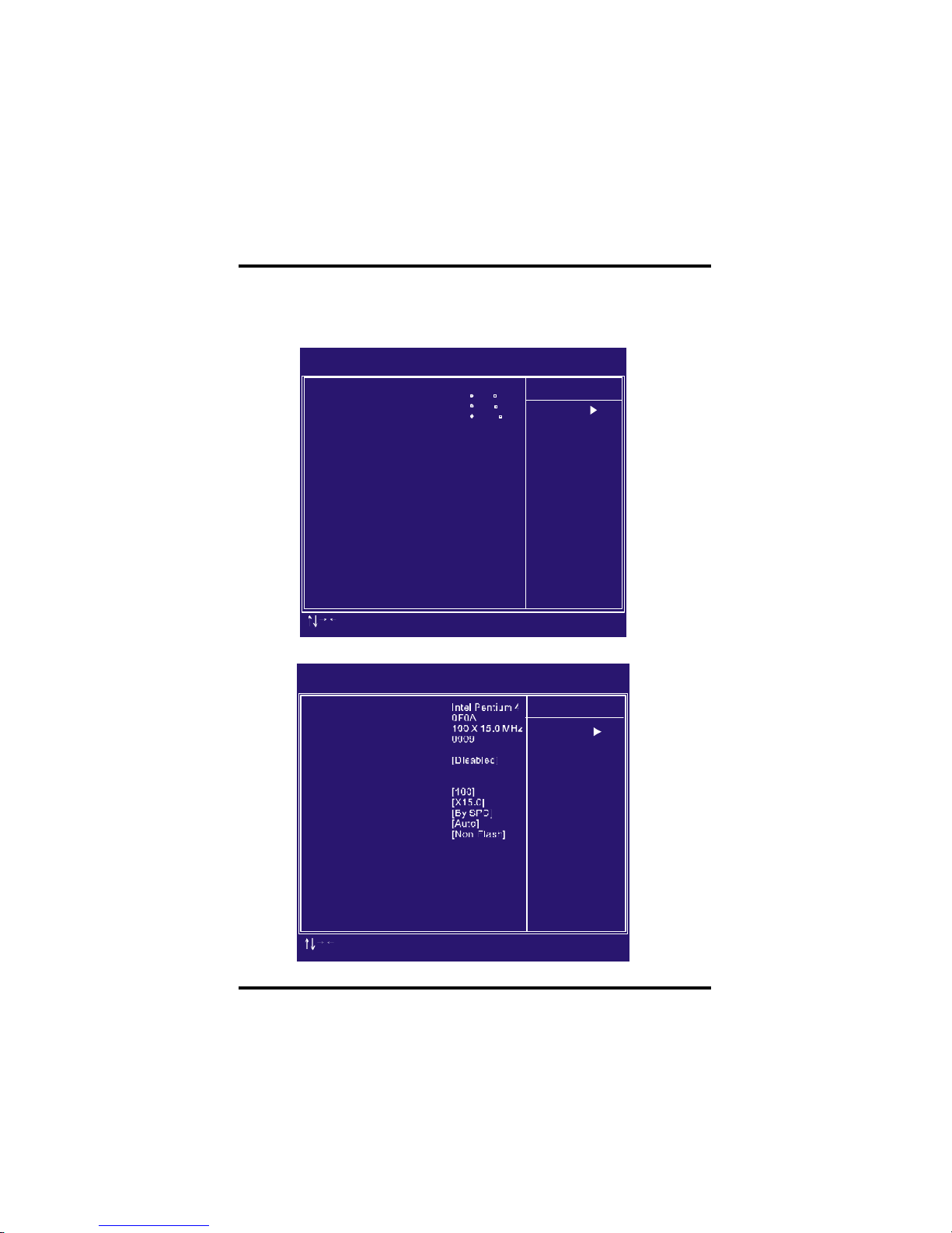
This page is monitoring your status of computer. On the screen displays
C PU/System tem perature, FAN speed, and voltages.
Page 43

43
Chapter 4 BIOS Setup
IWILL MicroStepping
MicroStepping
Microst epping is Iwill's another step forward to provides users a
f uss free CPU frequency set up procedure. It contains two main
f unctions, Auto D etecting CPU s speed and Micro Adjustable CPU
FSB speed.
Auto Detecting CPU speed:
IWILL MicroStepping will auto detect the CP U's factory m ultiplier
setting and C PU FSB to the f actory def ault. This function provides
a "f uss free" CP U set up process for the general users.
Micr o Adjustable CPU FSB speed:
IWILL provides a user friendly overclocking function that allows
users to experience the f un of overclocking. This function allows
user to adjust C PU FSB by 1MHz interval. This is particularly
usef ul when user wants to extract the m ost out of the purchased
C PU. For example: you select f rom 133, 134, 135, 136, 137,
138MH z and up to the maxim um speed that the system can
sustained.In the time should overclocking failed, MicroStepping
will auto detects the CP U's factory m ultiplier setting and set the
C PU FSB to default 66MHz, to protect the CPU installed.
Spread Spectrum
This item configures radiation emitted from the system. When
enabled, system will release less radiation
[E nabled,Disabled(Default Value)]
CPU Vcore Setting
This item display the current status of CP U voltages.
[Auto (De fault Value), 1.1 25V, 1.150V, 1.175V, 1.200V,1.225V,
1.250 V,1.275V,1.300V,1.325V,1.350V,1.375V,1.400V,1.425V,
1.450 V,1.525V,1.550V,1.575V,1.600V,1.625V,1.650V,1.675V,
1.700V,1.725V,1.750V,1.775V,1.800V,1.825V,1.850V]
BIOS-ROM Flash Protect
When select “Non flash”, the BIOS ROM chip will be protecte to
prevent injuring by Virus “please don’t select Flashable” until you
have to upgrade the latest BIOS.
[N on-Flash(Default Value), Flashable]
Page 44
44
Chapter 4 BIOS Setup
Load Fail Safe Defaults
Load Optimized Defaults
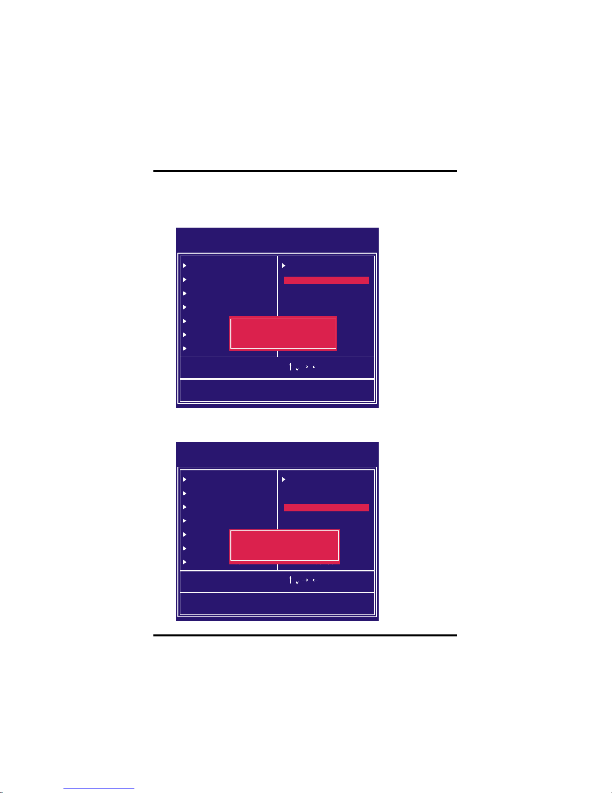
When you press <Enter> on this item you get a confirmation dialog box
with a message similar to:
CMOS Setup Utility-Copyright(c) 1984-2001 Award Software
Standard CMOS Features
Advanced BIOS Features
Advanced Chipset Features
Integrated Peripherals
Power Management Setup
PnP/PCI Configurations
PC Health Status
ESC: Quit
F10: Save & Exit Setup
Load Fail-Safe Defaults
: Select Item
IWILL Smart Setting
Load Fail-Safe Defaults
Load Optimized Defaults
Set Supervisor Password
Set User Password
Save & Exit Setup
Exit Without Saving
Load Fail-Safe Defaults (Y/N)?
CMOS Setup Utility-Copyright(c) 1984-2001 Award Software
Standard CMOS Features
Advanced BIOS Features
Advanced Chipset Features
Integrated Peripherals
Power Management Setup
PnP/PCI Configurations
PC Health Status
ESC: Quit
F10: Save & Exit Setup
Load Optimized Defaults
: Select Item
IWILL Smart Setting
Load Fail-Safe Defaults
Load Optimized Defaults
Set Supervisor Password
Set User Password
Save & Exit Setup
Exit Without Saving
Load Optimized Defaults (Y/N)?
When you press <Enter> on this item you get a confirmation dialog box
with a message similar to: Pressing ‘Y’ loads the BIOS default values for
the m ost stable, minimal-performance system operations.
Page 45
45
Chapter 4 BIOS Setup
CMOS Setup Utility-Copyright(c) 1984-2001 Award Software
Standard CMOS Features
Advanced BIOS Features
Advanced Chipset Features
Integrated Peripherals
Power Management Setup
PnP/PCI Configurations
PC Health Status
ESC: Quit
F10: Save & Exit Setup
Load Optimized Defaults
: Select Item
IWILL Smart Setting
Load Fail-Safe Defaults
Load Optimized Defaults
Set Supervisor Password
Set User Password
Save & Exit Setup
Exit Without Saving
Enter Password:
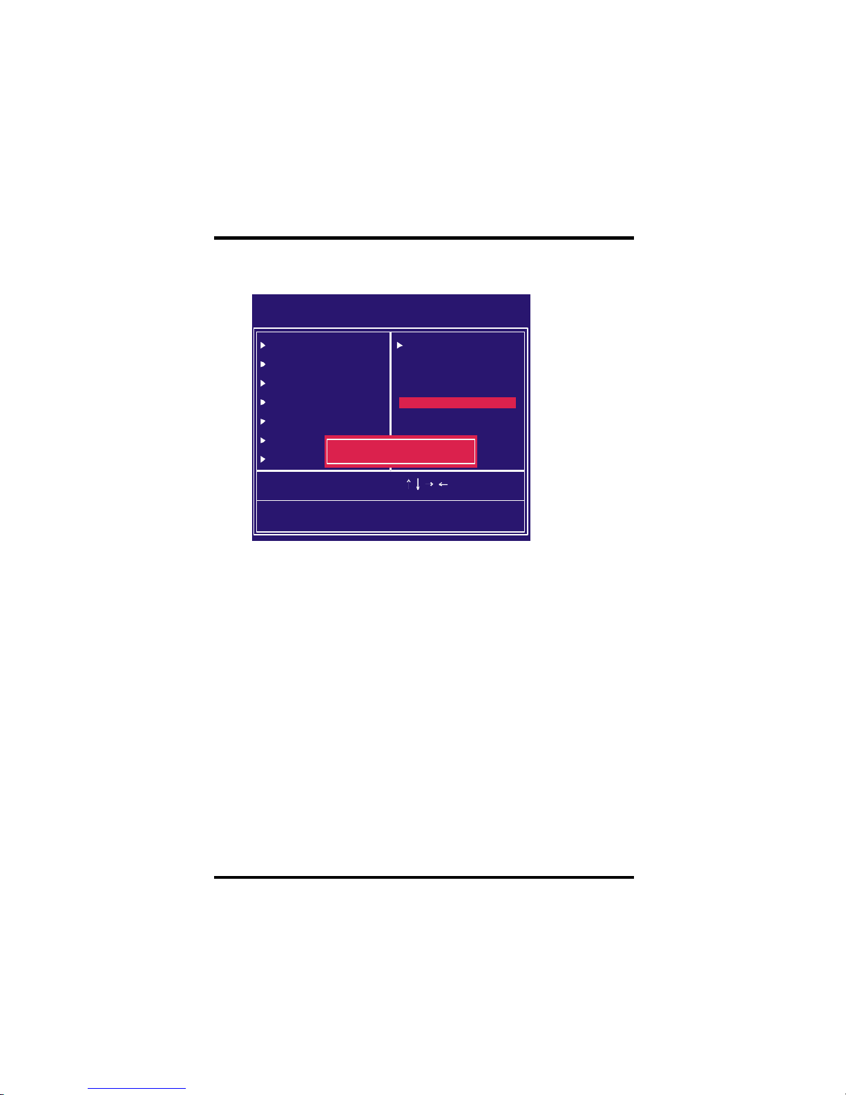
be required to enter the password every tim e you try to enter BIOS Setup
program. This prevents an unauthorized person from changing any part
of your system configuration. Additionally, if the Security Option field is
set as Boot, the BIOS will request a password every time your system
boot. This would prevent unauthorized use of your computer.
If you wish to use this function, bring the cursor to this field, then press
<E nter>. The computer will display the message, “Enter Password”.
Type your password and press <Enter>. After the message onfirm
P assword” is displayed, re-type your password. The Supervisor
P assword function will be in effect after you save and exit setup.
To disable a password, bring the cursor to this field, then press <E nter>.
The com puter will display the message, “E nter Password”. Press
<E nter>. A message will confirm that the password is disabled. Once the
password is disabled, the system will boot and you can enter setup
program freely.
These setup pages are used for password setting. When a password has
been enabled and the Security Option field is set as Setup, you will
Set Supervisor/ User Password Setting
Page 46
46
Chapter 4 BIOS Setup
Exit Without Saving
Save & Exit Setup
CMOS Setup Utility-Copyright(c) 1984-2001 Award Software
Standard CMOS Features
Advanced BIOS Features
Advanced Chipset Features
Integrated Peripherals
Power Management Setup
PnP/PCI Configurations
PC Health Status
ESC: Quit
F10: Save & Exit Setup
Save Data to CMOS
: Select Item
IWILL Smart Setting
Load Fail-Safe Defaults
Load Optimized Defaults
Set Supervisor Password
Set User Password
Save & Exit Setup
Exit Without Saving
SAVE to CMOS and EXIT(Y/N)?
CMOS Setup Utility-Copyright(c) 1984-2001 Award Software
Standard CMOS Features
Advanced BIOS Features
Advanced Chipset Features
Integrated Peripherals
Power Management Setup
PnP/PCI Configurations
PC Health Status
ESC: Quit
F10: Save & Exit Setup
Abandon all Datas
: Select Item
IWILL Smart Setting
Load Fail-Safe Defaults
Load Optimized Defaults
Set Supervisor Password
Set User Password
Save & Exit Setup
Exit Without Saving
Quit Without Saving (Y/N)?
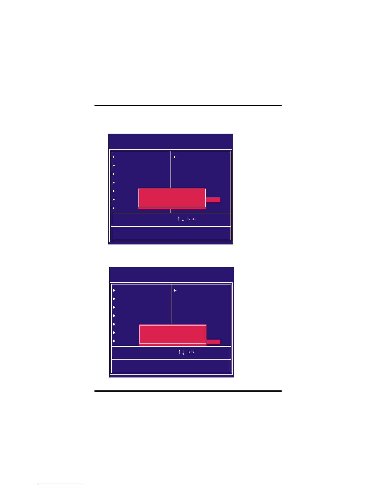
Saves current CMOS value and exit BIOS setup program .
Abandons all CMOS value changes and exits BIOS setup program.
Page 47
47
Chapter 5 On board Audio
Audio Features
Spec ial Feature
1. Full-duplex playback and recording. Built-in 16-bit CODEC.
2. H RTF 3D positional audio, supporting both DirectSound
3D&A3D interfaces. Also supports earphones, 2/4/6 channel
speakers mode.
3. Support Windows 98/Windows 2000 and Windows NT 4.0.
4.Built-in 32 OH M Earphone buff er.
5. MP U-401 Gam e/Midi port and legacy audio SB Pro support.
6. Downloadable Wave Table Synthesizer, supporting Direct
M usic.
Digital Audio (SPDIF IN/OUT)
1. U p to 24-bit stereo 44KHz sampling rate; voice playback/
recording
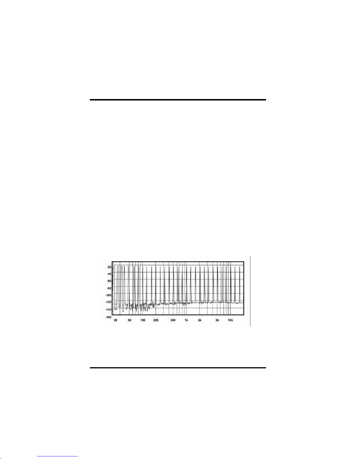
2. Full-duplex playback and recording. 120dB audio quality
measured.
3. Auto detectable SP DIF/IN signal level from 0.5V to 5V.
120 dB audio quality in playback, recording, and by pass modes.
O n board A udio
Page 48

Chapter 5 On board Audio
48
Stereo Mixer
Game and Midi Interface
Fully compatible with MPU-401 Midi UART and Sound Blaster
1. Stereo analog mixing from CD-Audio and Line-in
2. Stereo digital mixing from Voice, FM/Wave-table, and Digital
C D -Audio
3. Mono mixing from MIC. Software adjustable volum e.
Midi mode/Standard IBM P C joystick/game port
Page 49
49
Chapter 5 On board Audio
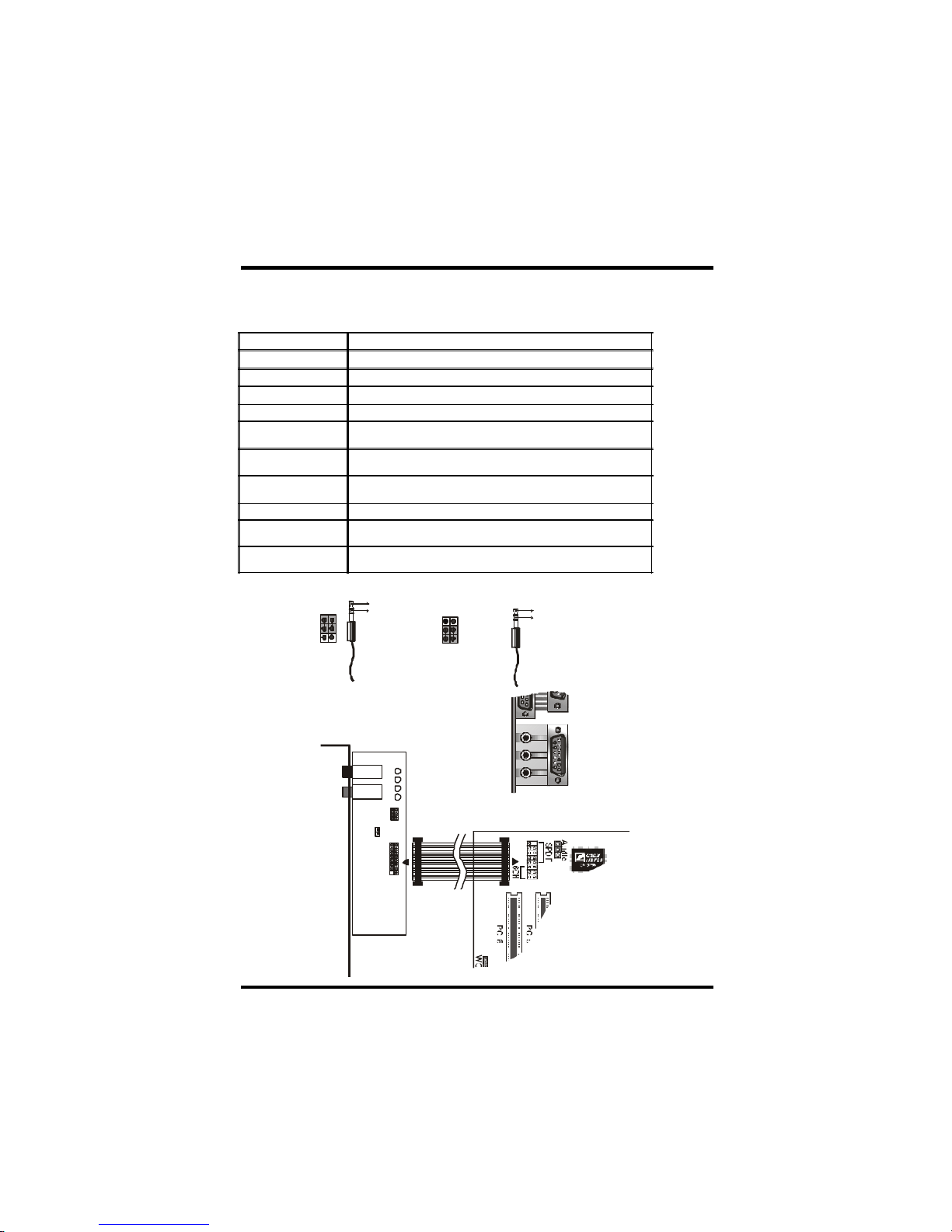
IWILL 6Channels Audio/ SuperAudio (Optional)
JP5 Audio Extension (Digital I/O) Connector
JP7 CD-SPDIF IN
JP10 BASS/Center Select
Line-IN LINE-IN Connect to the audio output port of stereo
Mic-IN Connect to the Microphone (Mono)
Front- Speaker
Output to speakers with the amplifier or earphones or AUDIO-IN of
home stereo
Rear-Speaker
Connect to the rear speakers while four/six channel speakers mode
is enabled
Center/BASS
Connect to the center speaker and BASS while six channel speakers
mode is enabled
GAME/MIDI Connect to Joystick or devices using MIDI interface
RCA SPDIF IN/OUT
Connects to digital audio devices such as DAT and MiniDisc
recorders, via RCA input/output
Optical SPDIF IN/OUT
Connects to digital audio devices such as DAT and MiniDisc
recorders, via optical input/output
JP10 function
exChange
(BASS/Center) Channel
1
2
3
456
Default
1
2
3
4
5
6
BASS channel
Center channel
BASSl
Center channel
J10
Rear-Speaker
Center/BASS
Audio Cable
6Channels Audio
6CH-Audio
J5
1
2
3
4
5
6
J7
Front-Speaker
Line-IN
MIC-IN
Game/MIDI
Connectors and Jumpers
Page 50
Chapter 5 On board Audio
50
J10
Rear-Speaker
Center/BASS
RCA SPDIF IN
Optical SPDIF IN
RCA SPDIF OUT
Optical SPDIF OUT
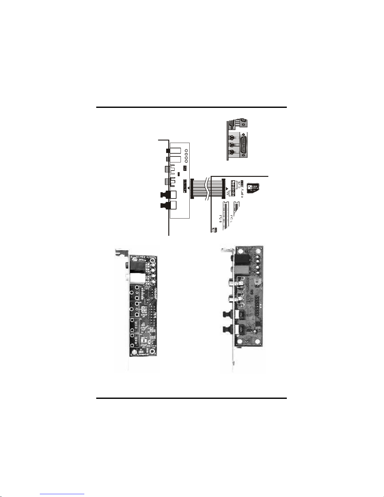
SuperAudio(Optional)
Audio Cable
Front-Speaker
Line-IN
MIC-IN
Game/MIDI
SuperAudio
J5
1
2
3
4
5
6
J7
IWILL 6Channels Audio IWILL SuperAudio (Optional)
Page 51

51
Chapter 5 On board Audio
Win 95/98/ME/2000 Un-Installation
1. C lick “Start”
2. Select “P rogram.”
3. Find “Uninstall device drivers and applications” program in P CI
audio applications.
4. R un it.
5. Follow the on-screen instructions to uninstall the device drivers
or applications.
Bef ore beginning the installation, please make sure that your hard
disk has suf ficient space(min. 4MB). Insert the Power Installer CD
into the C D -ROM Drive.
1. C hange directory to PCI audio DOS drivers folder
(ex. D:\D OSDRV) at DOS prom pt, and type: INSTALL[Enter]
2. Type the DOS utilities path you want to install the file in.
3. P rogram will expand the file to the path you’ve specified.
4. Install program will add initial drivers into AU TOEXEC.BAT file.
DOS Ins tallation
Driver Installation
Win 95/98/ME/2000 Installation
1. C lick “Start” at Windows bottom-left corner.
2. Select “R un”
3. Key in the drive path where the installation C D and installation
program are in; for exam ple, “D :\SETUP.EXE”
4. C lick “OK” to start the applications installation procedure, and
follow the on-screen instructions to complete the installation.
5. When all the application software has been installed, please
shut down Windows system, and reboot your system for new
driver installation. System will install the device drivers
automatically.
Page 52

Chapter 5 On board Audio
52
We recommend that you have Microsoft Windows N T intalled, and
remove any exsisting sound drivers from your current system ,
bef ore you install this PCI sound device driver.
1. C lick “Start” , move the highlight bar to “Setting”, and select the
“Control Panel”.
2. Double-click “Multim edia.”
3. Select “D evices”, and press “Add”
4. Select “Unlisted or Updated Driver” in List of Drivers.”
5. Specif y the drive path where NT drivers are in
(such as D:\N T40\DR V).
6. Select “C -Media CM8738,” and press “OK”.
7. Select prop er I/O value.
8. Press “OK.”
9. Restart the system when being asked.
10. Now, you have already installed the P CI Audio Adapter under
Microsof t Windows NT 4.0 successfully. If you want to install
the Windows applications, continue the following steps.
11. C lick “Start”
12. Select “R un”
13. Key in drive path where the Windows NT application
installation program are in;
for example, “D :\NT40\APP\SE TUP.EXE
14. C lick “OK” to start the installation procedure, and follow the on screen instructions to complete the installation. When all of
application software has been installed, shut down the
Windows NT system, then reboot your system.
Windows NT4.0 Installation
Page 53
53
Chapter 5 On board Audio
About Audio Rack
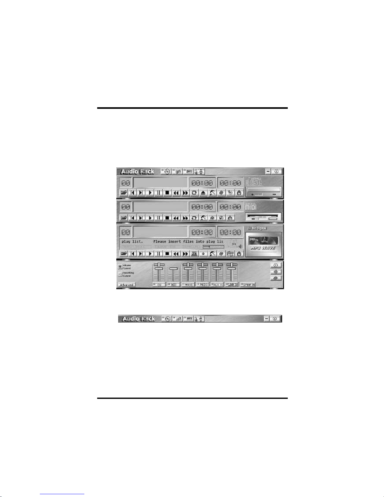
The Audio Rack is consisted of several major components.
Controls the display of the PCI Audio Rack’s components.
Control Center
Introduction
By m eans of a user-friendly interface (as easy as operating your
home stereo system), this P CI audio rack provides you with the
control over your P C’s audio functions, including the advantage of
six speakers m ode enable/ disable, and perfect digital sound (
SP DIF version ONLY) input / output. control.
The Audio Rack
MIDI Player
MIDI Player can play MIDI files, *.mid/*.rmi, and allow you to
create your own playlist.
MP3/Wave Player
Records and plays digital audio (mp3/wave) files. Allows you to
create wave file playlists, and playback the wave files.
CD Player
Plays standard audio CDs. Allows you to create your favorite
song playlists.
Mixer
Controls the volume level of your audio inputs and outputs
Page 54
Chapter 5 On board Audio
54
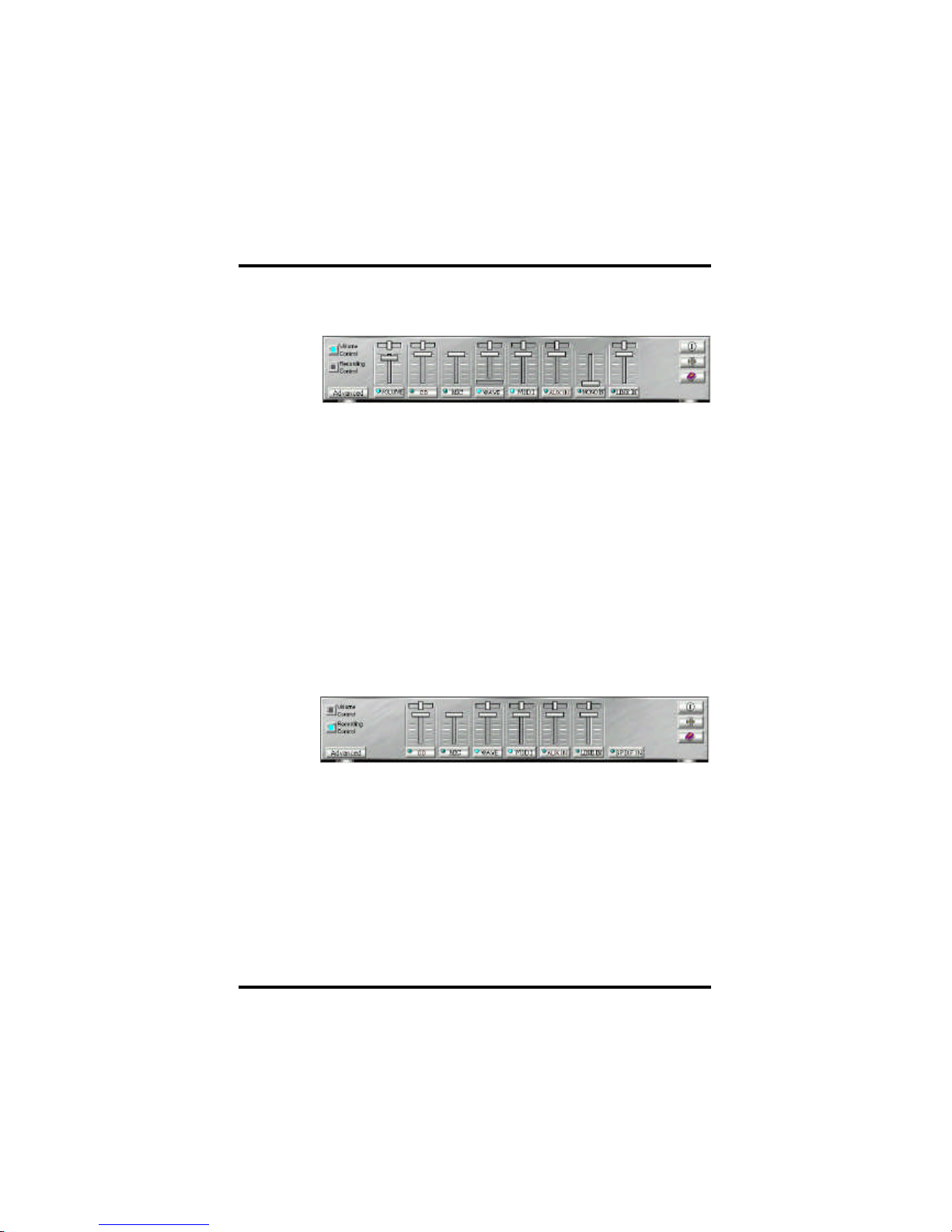
Volume Control
For each output signal, the control slider regulates the loudness whereas
a horizontal slider the balance between the two speakers. The mute
but ton can tem porarily stop the output without changing slider positions.
A button with a lit LE D m eans the output is availabl e, and vice versa.
Several output signals can usually be enabled at once.
V olume: This is the m aster control over all outputs. The power of an
outputRe signal is d eterm ined by both of the volume slider and the
slider for the individual output. To modify all the outputs, adjust the
volume slider. To change individual output(s), adjust its(their) slider(s).
CD: R egulates the CD drive audio input level.
MIC: Regulates the input level of microphone.
WAV E: Regulates wave (voice) playback levels.
MIDI: R egulates the MIDI m usic play level.
AUX IN: R egulates the Auxiliary input play level.
MONO IN: R egulates the Mono input level.
LINE IN: Regulates the Line-In levels.
Advanced: Regulates the advanced settings.
Recording Control
For each input signal, a control slider regulates the loudness wher eas
a horizontal slider the balance between the two channels. The se
lect button can temporarily select input signal without changing slider
positions. A button with a lit LE D m eans it is available, and vice versa.
CD: R egulates the CD drive audio input level.
MIC: R egulates the input level of microphone.
WAV E: Regulates wave (voice) playback level.
FM: R egulates the FM music play level.
AUX IN: R egulates the Auxiliary input play level.
LINE IN: R egulates the Line-In level.
SPDIF IN: E nables the recording from SPDIF in. SPDIF-in is mutu
ally exclusive with other input signals.
Advanced: Regulates the advanced settings.
Mixer
Page 55
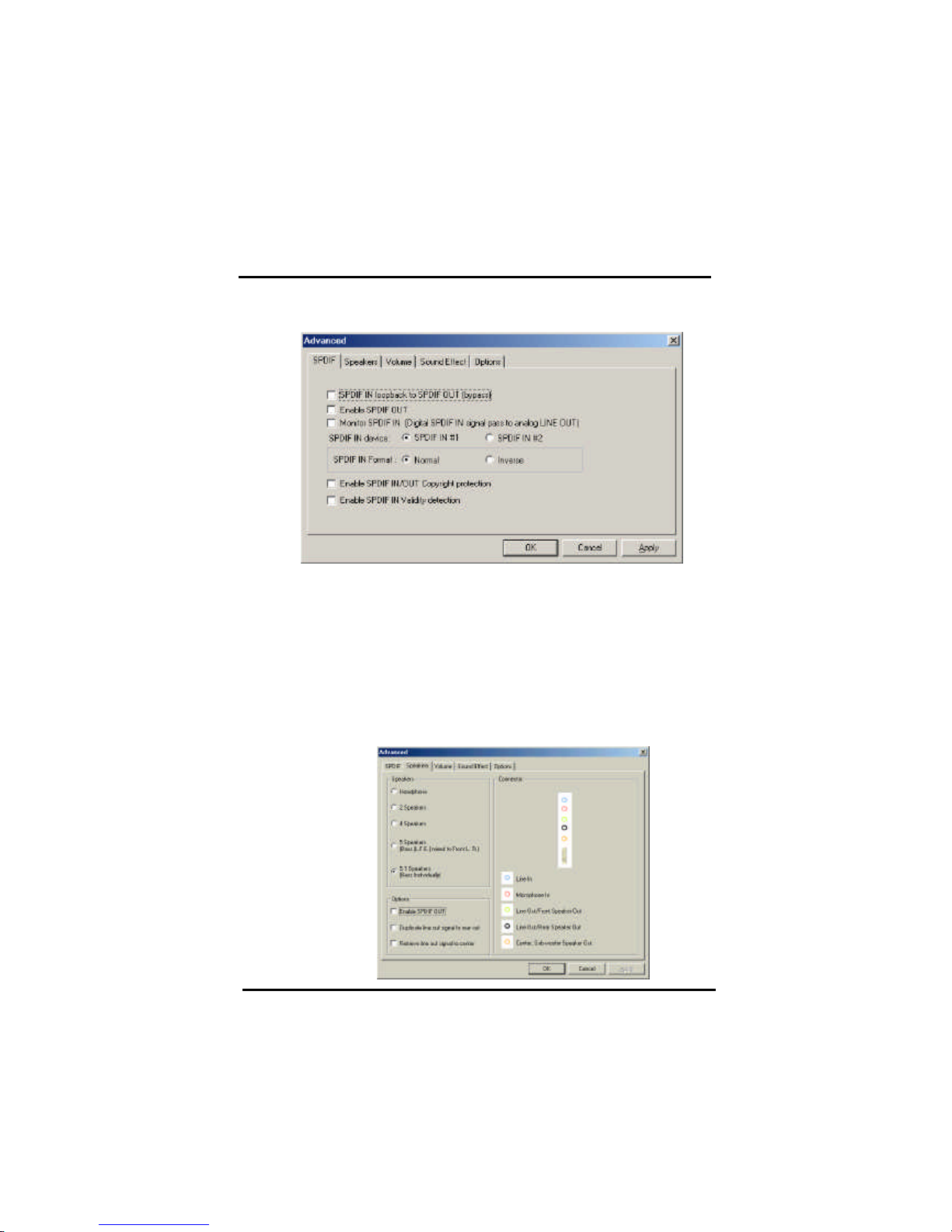
Advanced - SPDIF
SP DIF dialog provides a f ull control over SP DIF IN/OUT functions. You
can use these settings to connect your computer to other pieces of audio device, such as: Mini Disc players, am plifiers… etc.
Advanced - Speakers
Speakers dialog provides an interface allowing you to set your speakers
conf igurations. First, You should make sure what model type your speakers are , and what the correct configurations are. And this dial og also
shows the current status and functions of the phone jacks of your audio
devi ce. You can always ref er to th is to m ake sure whether or not the
connections of your speakers and microphone are correct.
Chapter 5 On board Audio
55
Page 56
Chapter 5 On board Audio
56
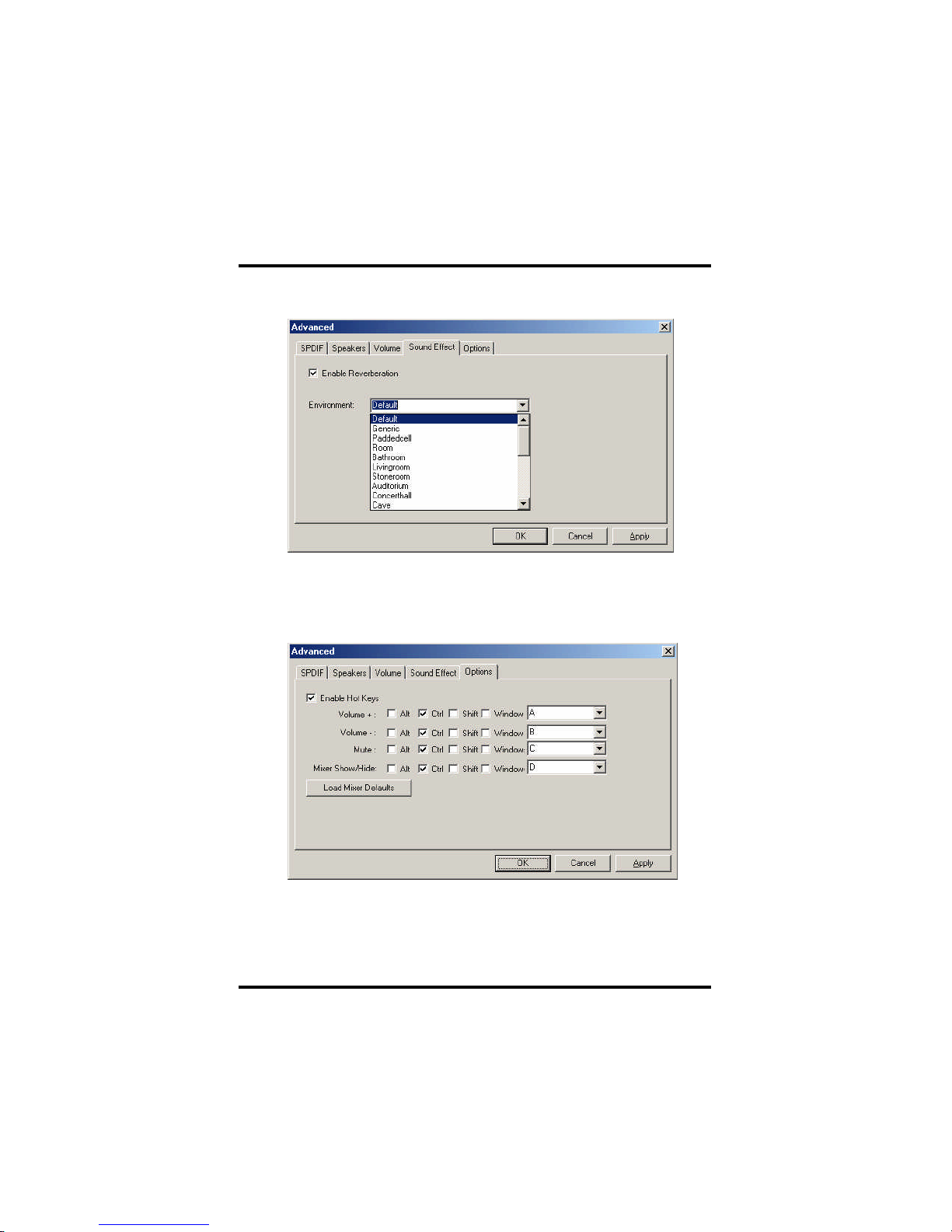
Advanced - S ound effects
Sound e ffects dialog allows you to m odify the special ef fects of the
song and game being played. C urrently, these eff ectors can only be
used for the player or the gam e which ut ilizes D irectSound 2D and 3D
to playback their music.
Advanced - Options
Options dia log provides a hot k ey setting to control the Mixer i n an
easy way. Please note that other applications might be affected by this
if you use the same hot key setting.
P lease use ‘Load Mixer Def aults’ to change all settings to default values.
 Loading...