

Page 1
Pundit P3-PE5
ASUS PC (Desktop Barebone)
Page 2
E300 7
Firs t E diti o n V1
Octo b e r 200 6
Copyright © 2006 ASUSTeK COMPUTER INC. All Rights Reserved.
No part of this manual, including the products and software described in it, may be reproduced,
transmitted, transcribed, stored in a retrieval system, or translated into any language in any form
or by any means, except documentation kept by the purchaser for backup purposes, without the
express written permission of ASUSTeK COMPUTER INC. (“ASUS”).
Product warranty or service will not be extended if: (1) the product is repaired, modied or
altered, unless such repair, modication of alteration is authorized in writing by ASUS; or (2) the
serial number of the product is defaced or missing.
ASUS PROVIDES THIS MANUAL “AS IS” WITHOUT WARRANTY OF ANY KIND, EITHER EXPRESS
OR IMPLIED, INCLUDING BUT NOT LIMITED TO THE IMPLIED WARRANTIES OR CONDITIONS OF
MERCHANTABILITY OR FITNESS FOR A PARTICULAR PURPOSE. IN NO EVENT SHALL ASUS,
ITS DIRECTORS, OFFICERS, EMPLOYEES OR AGENTS BE LIABLE FOR ANY INDIRECT, SPECIAL,
INCIDENTAL, OR CONSEQUENTIAL DAMAGES (INCLUDING DAMAGES FOR LOSS OF PROFITS, LOSS
OF BUSINESS, LOSS OF USE OR DATA, INTERRUPTION OF BUSINESS AND THE LIKE), EVEN IF ASUS
HAS BEEN ADVISED OF THE POSSIBILITY OF SUCH DAMAGES ARISING FROM ANY DEFECT OR
ERROR IN THIS MANUAL OR PRODUCT.
SPECIFICATIONS AND INFORMATION CONTAINED IN THIS MANUAL ARE FURNISHED FOR
INFORMATIONAL USE ONLY, AND ARE SUBJECT TO CHANGE AT ANY TIME WITHOUT NOTICE, AND
SHOULD NOT BE CONSTRUED AS A COMMITMENT BY ASUS. ASUS ASSUMES NO RESPONSIBILITY
OR LIABILITY FOR ANY ERRORS OR INACCURACIES THAT MAY APPEAR IN THIS MANUAL,
INCLUDING THE PRODUCTS AND SOFTWARE DESCRIBED IN IT.
Products and corporate names appearing in this manual may or may not be registered
trademarks or copyrights of their respective companies, and are used only for identication or
explanation and to the owners’ benet, without intent to infringe.
ii
Page 3
Table of contents
Notices ................................................................................................ vi
Safety information ..............................................................................vii
About this guide .................................................................................viii
System package contents .................................................................... x
Cha p te r 1 : S y ste m I n tro d uc t ion
1.1 Welcome! .............................................................................. 1-2
1.2 Front panel ............................................................................
1.3 Rear panel .............................................................................
1.4 Internal components .............................................................
Cha p te r 2 : Bas i c I nst a ll a tio n
2.1 Preparation ........................................................................... 2-2
2.2 Before you proceed ..............................................................
2.3 Removing the cover and front panel assembly .....................
2.4 Central Processing Unit (CPU) ..............................................
2.4.1 Overview .................................................................
2.4.2 Installing CPU ..........................................................
2.4.3 Installing the CPU fan and heatsink assembly .........
2.5 Installing a DIMM ...................................................................
2.5.1 Memory congurations ...........................................
2.5.2 Installing a DDR2 DIMM ...........................................
2.5.3 Removing a DDR2 DIMM ..........................................
2.6 Expansion slots ...................................................................
2.6.1 Installing an expansion card ..................................
2.6.2 Conguring an expansion card ..............................
2.6.3 PCI Express x 1 slot ..............................................
2.6.4 PCI slots ................................................................
2.6.5 PCI Express x 16 slot ............................................
2.7 Installing an optical drive ....................................................
2.8 Removing the card reader
2.9 Installing hard disk drivers (HDDs) ......................................
2.9.1 Hard disk drive bays ..............................................
2.9.2 SATA hard disk drive installation ..........................
2.9.3 IDE hard disk drive installation ..............................
2.9.4 Uninstalling a hard disk drive ................................
................................................... 2-15
1-2
1-4
1-6
2-2
2-3
2-4
2-4
2-4
2-6
2-7
2-7
2-9
2-9
2-10
2-10
2-10
2-12
2-12
2-12
2-13
2-16
2-16
2-16
2-16
2-16
iii
Page 4
Table of contents
2.10 Replacing the covers ........................................................... 2-19
2.10.1 Replacing the front panel assembly ......................
2.10.2 Replacing the system cover ..................................
2.11 Installing the foot stands ....................................................
Cha p te r 3 : Sta r ti n g u p
3.1 Installing an operating system .............................................. 3-2
3.2 Powering up ..........................................................................
3.3 Support CD information ........................................................
3.3.1 Running the support CD ..........................................
3.3.2 Utilities menu ..........................................................
3.3.3 Make Disk ................................................................
3.3.4 ASUS contact information ......................................
3.4 Software information ............................................................
Cha p te r 4 : Mot h er b oar d I n fo
4.1 Introduction .......................................................................... 4-2
4.2 Motherboard layout ..............................................................
4.3 Jumpers ................................................................................
4.4 Connectors ...........................................................................
2-19
2-20
2-21
3-2
3-2
3-3
3-4
3-5
3-5
3-6
4-2
4-3
4-6
Cha p te r 5 : BIO S I n for m at i on
5.1 Managing and updating your BIOS ........................................ 5-2
5.1.1 ASUS Update utility ................................................
5.1.2 Creating a bootable oppy disk ..............................
5.1.3 ASUS EZ Falsh .........................................................
5.1.4 AwardBIOS Flsh Utility .............................................
5.1.5 Saving the current BIOS le ....................................
5.1.6 ASUS CrashFree BIOS 2 utility ..............................
5.2 BIOS setup program ............................................................
5.2.1 BIOS menu screen .................................................
5.2.2 Menu bar ...............................................................
5.2.3 Legend bar ............................................................
iv
5-2
5-5
5-6
5-7
5-9
5-10
5-11
5-12
5-12
5-13
Page 5

Table of contents
5.2.4 Menu items ........................................................... 5-13
5.2.5 Sub-menu items ....................................................
5.2.6 Conguration elds ...............................................
5.2.7 Pop-up window ......................................................
5.2.8 General help ..........................................................
5.3 Main menu ...........................................................................
5.3.1 System Time ........................................................
5.3.2 System Date ........................................................
5.3.3 Primary IDE Master/Slave ......................................
5.3.4 First/Second SATA Master ...................................
5.3.5 HDD SMART Monitoring .........................................
5.4 Advanced menu ..................................................................
5.4.1 CPU Condiguration ................................................
5.4.2 Chipset ..................................................................
5.4.3 PCIPnP ...................................................................
5.4.4 Onboard Device Conguration ..............................
5.4.5 USB Conguration .................................................
5.5 Power menu ........................................................................
5.5.1 ACPI Suspend Type ...............................................
5.5.2 ACPI APIC Support ................................................
5.5.3 APM Conguration ................................................
5.5.4 Hardware Monitor ..................................................
5.6 Boot menu ..........................................................................
5.6.1 Boot Device Priority ..............................................
5.6.2 Hard Disk Drives ....................................................
5.6.3 Boot Settings Conguration .................................
5.6.4 Security .................................................................
5.7 Exit menu ............................................................................
5-13
5-13
5-14
5-14
5-15
5-15
5-15
5-16
5-18
5-19
5-19
5-20
5-21
5-23
5-24
5-25
5-26
5-26
5-26
5-27
5-29
5-31
5-31
5-31
5-32
5-33
5-34
v
Page 6
Notices
Fed er al Co mm un ica ti on s C om mi ssi on S tat em en t
This device complies with Part 15 of the FCC Rules. Operation is subject to
the following two conditions:
•
This device may not cause harmful interference, and
•
This device must accept any interference received including
interference that may cause undesired operation.
This equipment has been tested and found to comply with the limits for a
Class B digital device, pursuant to Part 15 of the FCC Rules. These limits
are designed to provide reasonable protection against harmful interference
in a residential installation. This equipment generates, uses and can radiate
radio frequency energy and, if not installed and used in accordance with
manufacturer’s instructions, may cause harmful interference to radio
communications. However, there is no guarantee that interference will
not occur in a particular installation. If this equipment does cause harmful
interference to radio or television reception, which can be determined by
turning the equipment off and on, the user is encouraged to try to correct
the interference by one or more of the following measures:
•
Reorient or relocate the receiving antenna.
•
Increase the separation between the equipment and receiver.
•
Connect the equipment to an outlet on a circuit different from that to
which the receiver is connected.
•
Consult the dealer or an experienced radio/TV technician for help.
WARNING! The use of shielded cables for connection of the monitor to
the graphics card is required to assure compliance with FCC regulations.
Changes or modications to this unit not expressly approved by the
party responsible for compliance could void the user’s authority to
operate this equipment.
Can ad ia n D ep ar tme nt o f C om mu nic at io ns St at eme nt
This digital apparatus does not exceed the Class B limits for radio noise
emissions from digital apparatus set out in the Radio Interference
Regulations of the Canadian Department of Communications.
This class B digital apparatus complies with Canadian ICES-003.
vi
Page 7
Safety information
Ele ct ri cal s af ety
•
To prevent electrical shock hazard, disconnect the power cable from
the electrical outlet before relocating the system.
•
When adding or removing devices to or from the system, ensure that
the power cables for the devices are unplugged before the signal cables
are connected.
•
If the power supply is broken, do not try to fix it by yourself. Contact a
qualified service technician or your retailer.
Ope ra ti on sa fe ty
•
Before installing devices into the system, carefully read all the
documentation that came with the package.
•
Before using the product, make sure all cables are correctly connected
and the power cables are not damaged. If you detect any damage,
contact your dealer immediately.
•
To avoid short circuits, keep paper clips, screws, and staples away from
connectors, slots, sockets and circuitry.
•
Avoid dust, humidity, and temperature extremes. Do not place the
product in any area where it may become wet. Place the product on a
stable surface.
•
If you encounter technical problems with the product, contact a
qualified service technician or your retailer.
Lithium-Ion Battery Warning
CAUTION: Danger of explosion if battery is incorrectly replaced.
Replace only with the same or equivalent type recommended by
the manufacturer. Dispose of used batteries according to the
manufacturer’s instructions.
VORSICHT: Explosionsgetahr bei unsachgemäßen Austausch der
Batterie. Ersatz nur durch denselben oder einem vom Hersteller
empfohlenem ähnljchen Typ. Entsorgung gebrauchter Batterien nach
Angaben des Herstellers.
LASER PRODUCT WARNING
CLA SS 1 LA SE R PRO DU CT
vii
Page 8
About this guide
Aud ie nc e
This guide provides general information and installation instructions about
the ASUS Pundit P3 - PE5 barebone system. This guide is intended for
experienced users and integrators with hardware knowledge of personal
computers.
How t hi s g ui de is o rg ani ze d
This guide contains the following parts:
1. Chap t e r 1: S y s tem i n t rodu c t i on
This chapter gives a general description of the ASUS
Pundit P3 - PE5. The chapter lists the system features, including
introduction on the front and rear panel, and internal components.
2. Chap t e r 2: B a s ic i n s t alla t i o n
This chapter provides step-by-step instructions on how to install
components in the system.
3. Chap t e r 3: S t a rtin g u p
This chapter helps you power up the system and install drivers and
utilities from the support CD.
4. Chap t e r 4: M o t herb o a r d in f o r mati o n
This chapter gives information about the motherboard that comes
with the system. This chapter includes the motherboard layout,
jumper settings, and connector locations.
5. Chap t e r 5: B I O S in f o r mati o n
This chapter tells how to change system settings through the BIOS
Setup menus and describes the BIOS parameters.
viii
Page 9
Con ve nt ion s us ed in t his g ui de
WARNING: Information to prevent injury to yourself when trying
to complete a task.
CAUTION: Information to prevent damage to the components
when trying to complete a task.
IMPORTANT: Instructions that you MUST follow to complete a
task.
NOTE: Tips and additional information to aid in completing a
task.
Whe re t o f in d mor e in for ma ti on
Refer to the following sources for additional information and for product
and software updates.
1. ASUS W e bsit e s
The ASUS websites worldwide provide updated information on
ASUS hardware and software products. Refer to the ASUS contact
information.
2. Opti o n a l Do c u m enta t i o n
Your product package may include optional documentation, such as
warranty yers, that may have been added by your dealer. These
documents are not part of the standard package.
ix
Page 10
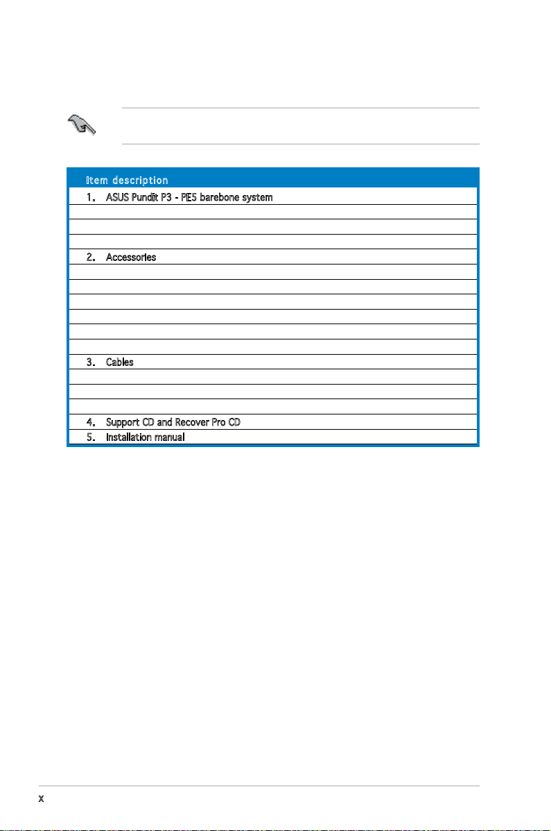
System package contents
Check your Pundit P3 - PE5 system package for the following items.
If any of the items is damaged or missing, contact your retailer
immediately.
Ite m d escri p t i on
1. ASUS Pundit P3 - PE5 barebone system with
• ASUS motherboard
• 275 W PFC power supply unit
• 6-in-1 storage card reader
2. Accessories
• CPU fan and heatsink assembly
• Foot stand and screw (1 pair) for vertical placement
• Rubber stand (x 4) for horizontal placement
• Hard disk drive screw (x 8)
• Optical drive screw (x 2)
• Rubber washer (x 8)
3. Cables
• AC power cable
• Serial ATA signal cable (x 2)
• IDE cable (x 2)
4. Support CD and Recover Pro CD
5. Installation manual
x
Page 11
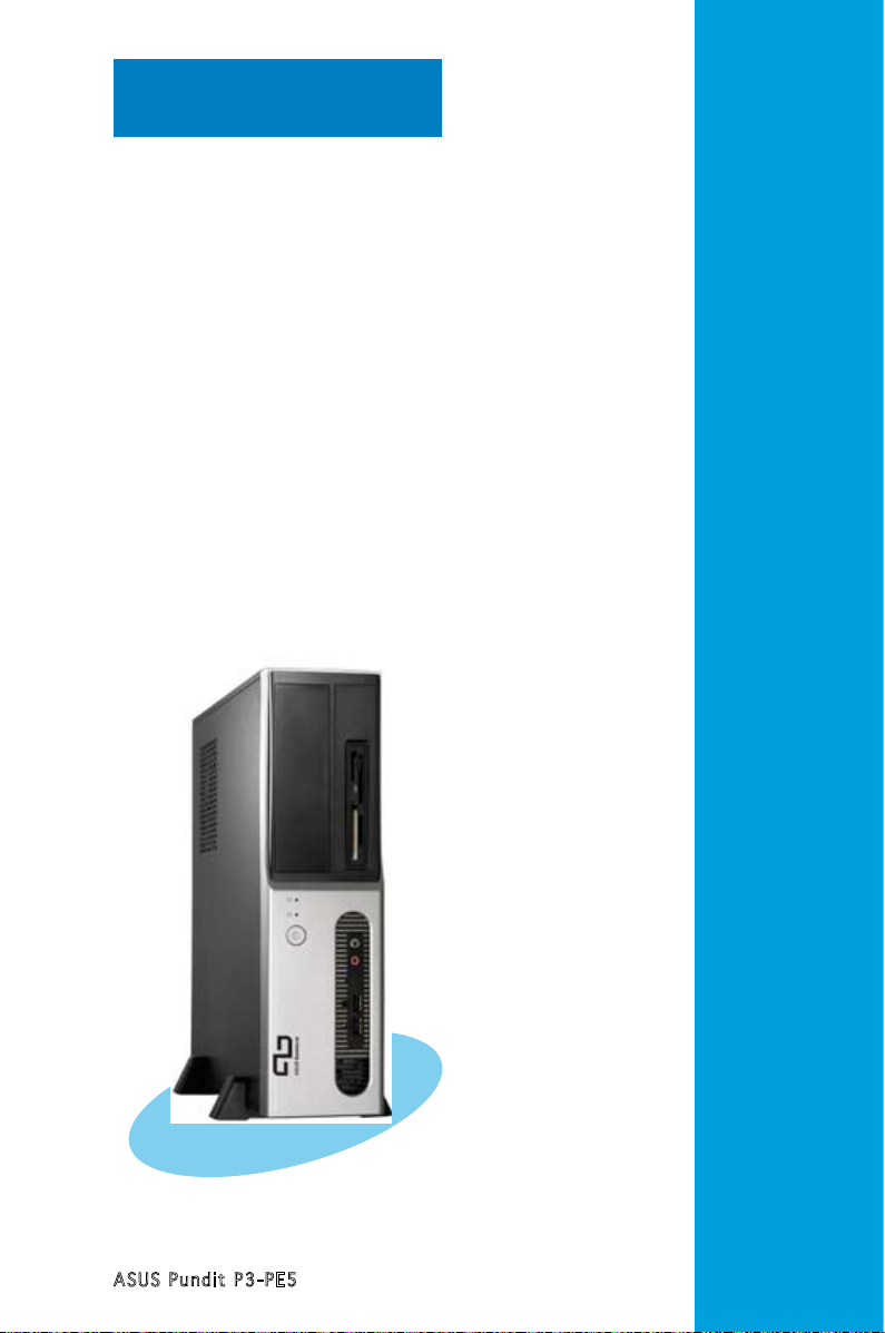
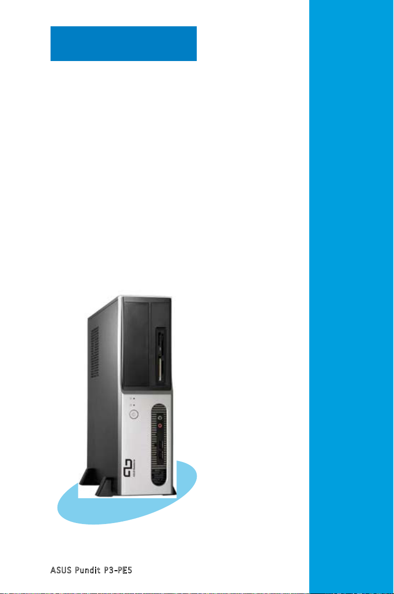
Chapter 1
This chapter gives a general
description of the ASUS
Pundit P3-PE5. The chapter lists
the system features including
introduction on the front and rear
panel, and internal components.
ASUS Pundit P3-PE5
System introduction
Page 12
1.1 Welcome!
Thank you for choosing the ASUS Pundit P3-PE5!
The ASUS Pundit P3-PE5 is an all-in-one barebone system with a versatile
home entertainment feature.
The system comes in a stylish mini-tower casing and powered by the ASUS
motherboard that supports the Intel® Pentium® D, Intel® Pentium® 4 or
Intel® Celeron® processor in the 775-land package.
The system supports up to 2 GB of system memory using
DDR2-533/400 DIMMs, high-resolution graphics via integrated graphics
controller or PCI Express x16 slot, Serial ATA, USB 2.0, and
6-channel audio features the system takes you ahead in the world of power
computing.
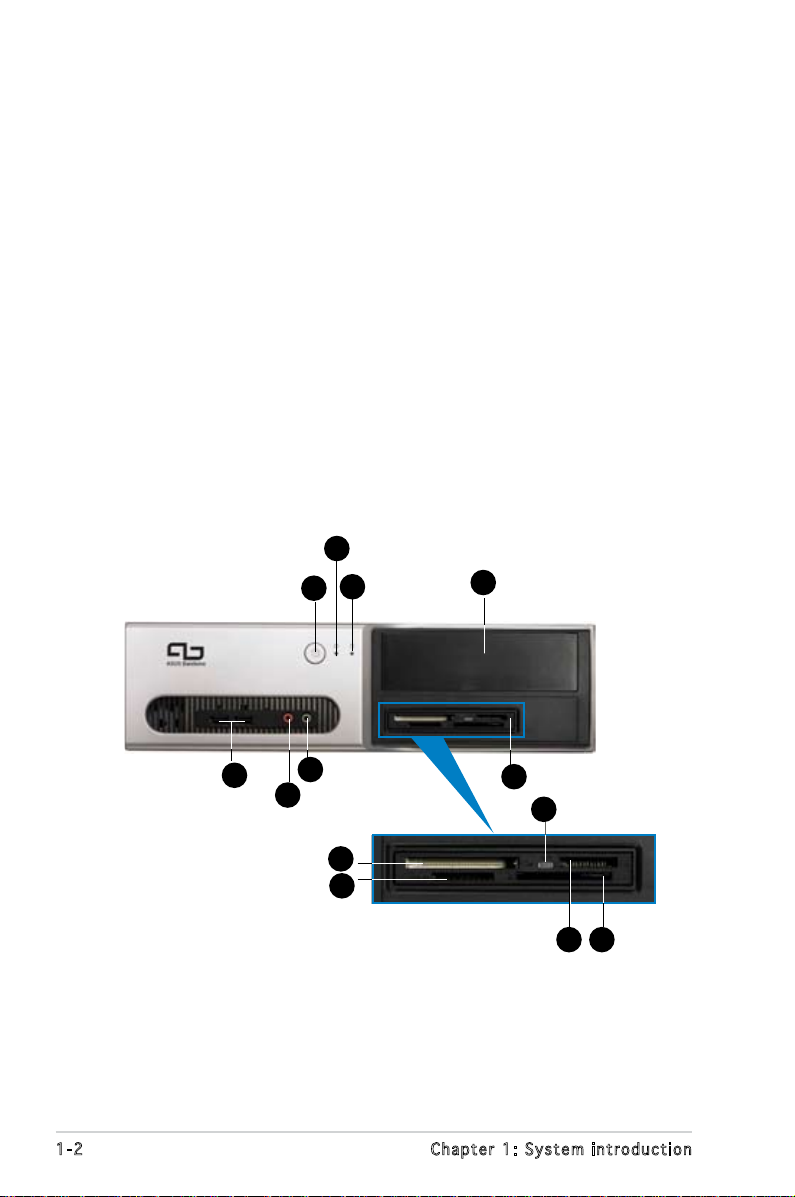
1.2 Front panel
The front panel includes the optical drive bays, power button, and several
I/O ports are located at the front panel.
4
1
3
5
1-2 Chapter 1: System introduction
7
6
11
12
2
8
10
9
13
Page 13
1. HDD LED. This LED lights up when data is read from or written to the
hard disk drive.
2. 5.25-inch bay. This bay is for an IDE optical drive.
3. Power button. Press this button to turn the system on.
4. Power LED.
5. USB 2.0 ports. These Universal Serial Bus 2.0 (USB 2.0) ports are
available for connecting USB 2.0 devices such as a mouse, printer,
scanner, camera, PDA, and others.
6. Microphone port. This Mic (pink) port connects a microphone.
7. Headphone port. This Line In (green) port connects a headphone with
a stereo mini-plug.
8. 6- in1 card reader.
9. Memory Stick/Pro
TM
Card slot.
10. Card reader LED.
11. CompactFlashTM Card slot.
12. Secure DigitalTM /MultimediaCard slot.
13. SmartMediaTM card slot.
1-3ASUS Pundit P3-PE5
Page 14
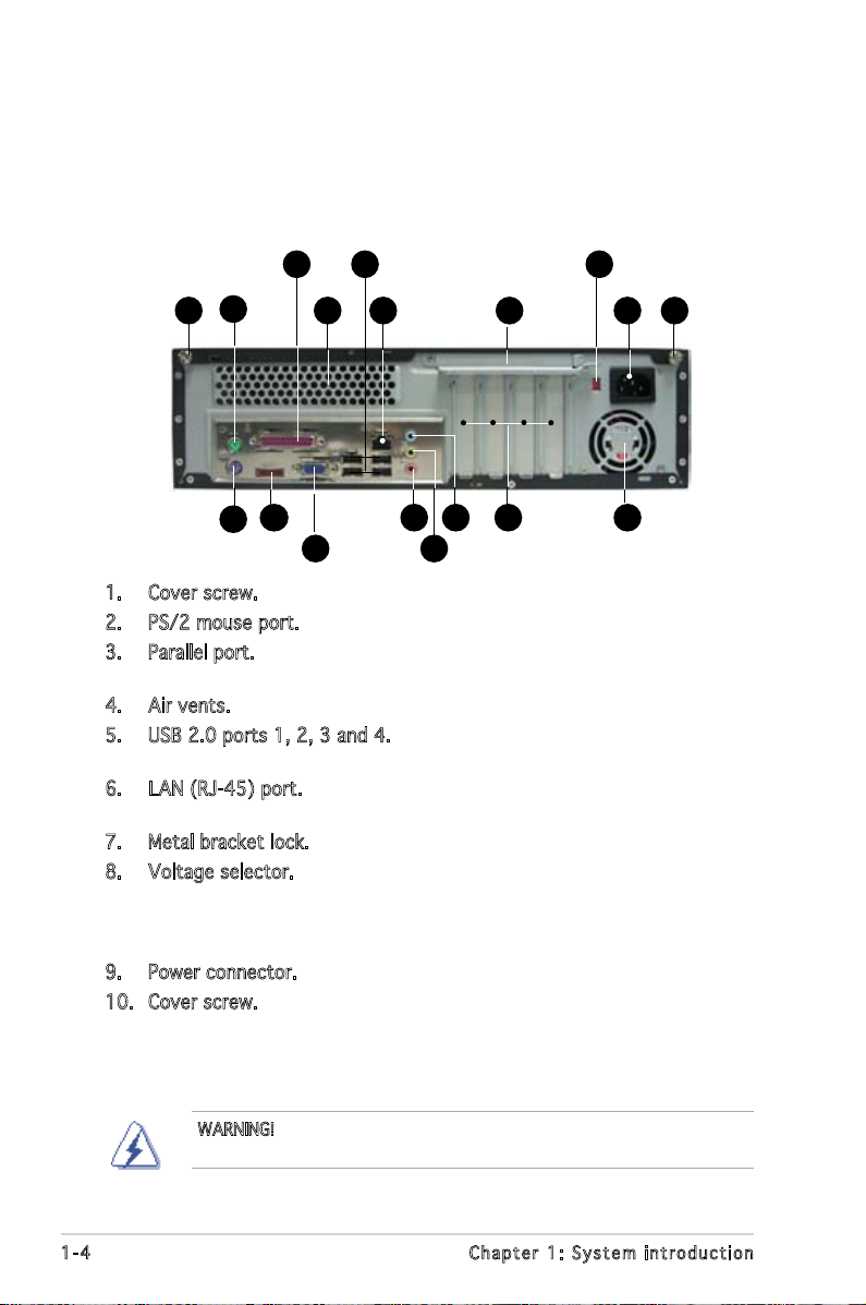
1.3 Rear panel
The system rear panel includes the power connector and several I/O ports
that allow convenient connection of devices.
3
2
1
12
11
5
4
6
14
13 15
7
8
10
9
1816 17
1. Cover screw.
2. PS/2 mouse port. This green 6-pin connector is for a PS/2 mouse.
3. Parallel port. This 25-pin port connects a printer, scanner, or other
devices.
4. Air vents.
5. USB 2.0 ports 1, 2, 3 and 4. These 4-pin Universal Serial Bus (USB)
ports are available for connecting USB 2.0 devices.
6. LAN (RJ-45) port. This port allows Gigabit connection to a Local Area
Network (LAN) through a network hub.
7. Metal bracket lock.
8. Voltage selector. This switch allows you to adjust the system input
voltage according to the voltage supply in your area. If the voltage
supply in your area is 100-127V, set this switch to 115V. If the
voltage supply in your area is 200-240V, set this switch to 230V.
9. Power connector. This connector is for the power cable and plug.
10. Cover screw.
WARNING! Setting the switch to 115V in a 230V environment or 230V
in a 115 environment will seriously damage the system!
1-4 Chapter 1: System introduction
Page 15
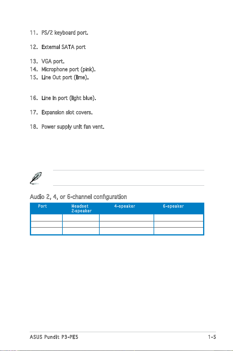
11. PS/2 keyboard port. This purple 6-pin connector is for a
PS/2 keyboard.
12. External SATA port. This port connects to an external SATA box or a
Serial ATA port multiplier.
13. VGA port. This port connects a VGA monitor.
14. Microphone port (pink). This port connects a microphone.
15. Line Out port (lime). This port connects a headphone or a speaker.
In 4-channel and 6-channel conguration, the function of this port
becomes Front Speaker Out.
16. Line In port (light blue). This port connects the tape, CD, DVD player,
or other audio sources.
17. Expansion slot covers. Remove these covers when installing expansion
cards.
18. Power supply unit fan vent. This vent is for the PSU fan that provides
ventilation inside the power supply unit.
Refer to the audio conguration table below for the function of the audio
ports in 2, 4, or 6-channel conguration.
Audio 2, 4, or 6-channel conguration
Por t He a d s et 4-s p e a ker 6- s p e a ker
2-spe a k e r
Light Blue Line In Surround Out Surround Out
Lime Line Out Front Speaker Out Front Speaker Out
Pink Mic In Mic In Center/Bass
1-5ASUS Pundit P3-PE5
Page 16
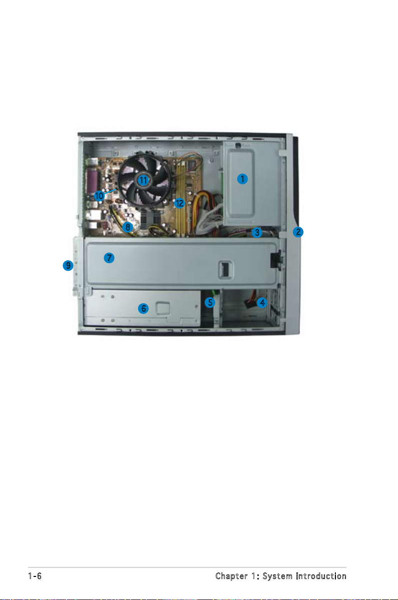
1.4 Internal components
The illustration below is the internal view of the system when you remove
the top cover. The installed components are labeled for your reference.
Proceed to Chapter 2 for instructions on installing additional system
components.
11
10
8
9
7
6
12
1. 5.25-inch empty optical drive bay
2. Front panel cover
3. Optical drive lock
4. Hard disk drive bays
5. Hard disk drive lock
6. Power supply unit
7. Chassis support bracket
1
3
5
4
2
8. ASUS motherboard
9. Metal bracket lock
10. LGA775 socket (under the CPU
fan and heatsink assembly)
11. CPU fan and heatsink assembly
12. DIMM sockets
1-6 Chapter 1: System introduction
Page 17
Chapter 2
This chapter provides step-by-step
instructions on how to install
components in the system.
ASUS Pundit P3-PE5
Basic installation
Page 18
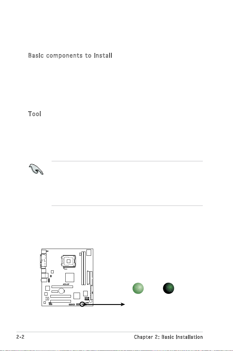
2.1 Preparation
R
Onboard LED
SB_PWR
ON
Standby
Power
OFF
Powered
Off
Before you proceed, make sure that you have all the components you plan
to install in the system.
Bas i c c omp o ne n ts t o i nst a ll
1. Central Processing Unit (CPU)
2. DDR2 Dual Inline Memory Module (DIMM)
3. Expansion card(s)
4. Hard disk drive
5. Optical drive
Too l
Phillips (cross) screw driver
2.2 Before you proceed
Take note of the following precautions before you install components into
the system.
•
Use a grounded wrist strap or touch a safely grounded object or
a metal object, such as the power supply case, before handling
components to avoid damaging them due to static electricity.
•
Hold components by the edges to avoid touching the ICs on them.
•
Whenever you uninstall any component, place it on a grounded
antistatic pad or in the bag that came with the component.
The motherboard comes with an onboard standby power LED. This LED
lights up to indicate that the system is ON, in sleep mode or in soft-off
mode, and not powered OFF. Unplug the power cable from the power outlet
and make sure that the standby power LED is OFF before installing any
system component.
2-2 Chapter 2: Basic installation
Page 19
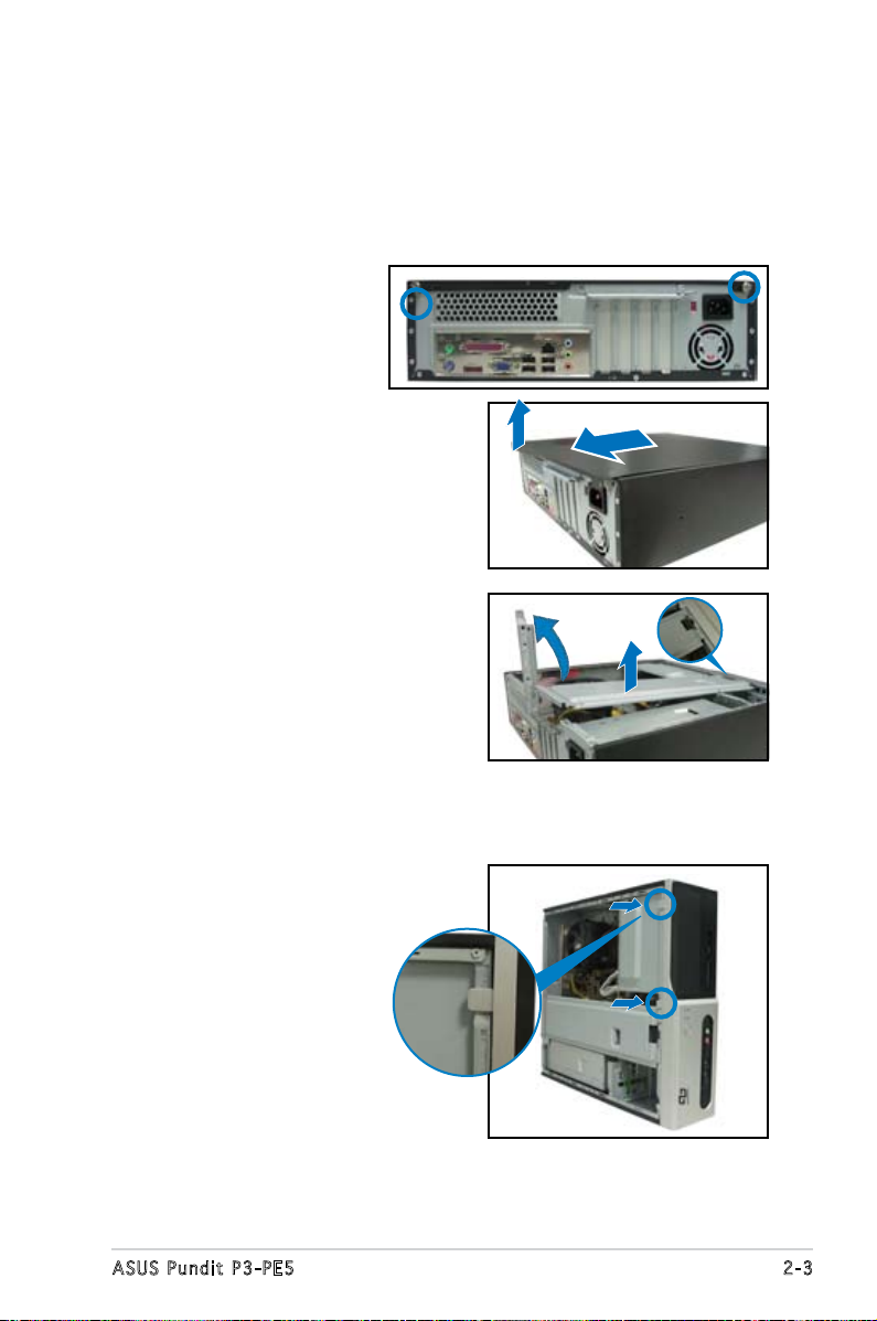
2.3 Removing the cover and front
panel assembly
To remove the cover:
1. Locate two cover
screws.
2. Remove the cover
screws.
3. Pull the cover.
4. Lift the cover, then set aside.
5. Lift the expansion card lock to
a 90º-100º angle.
6. Lift the chassis support
bracket, then remove.
To remove the front panel assembly:
1. Locate the front panel
assembly hooks.
2. Pull the hooks outward to
remove.
2-3ASUS Pundit P3-PE5
Page 20
2.4 Central Processing Unit (CPU)
2.4 .1 Ove rv ie w
The motherboard comes with a surface mount LGA775 socket designed for
the Intel® Pentium® 4 processor in the 775-land package.
• Your boxed Intel® Pentium® 4 LGA775 processor package should
come with installation instructions for the CPU, heatsink, and the
retention mechanism. If the instructions in this section do not match
the CPU documentation, follow the latter.
•
Check your motherboard to make sure that the PnP cap is on the
CPU socket and the socket contacts are not bent. Contact your
retailer immediately if the PnP cap is missing, or if you see any
damage to the PnP cap/socket contacts/motherboard components.
ASUS will shoulder the cost of repair only if the damage is shipment/
transit-related.
•
Keep the cap after installing the motherboard. ASUS will process
Return Merchandise Authorization (RMA) requests only if the
motherboard comes with the cap on the LGA775 socket.
• The product warranty does not cover damage to the socket
contacts resulting from incorrect CPU installation/removal, or
misplacement/loss/incorrect removal of the PnP cap.
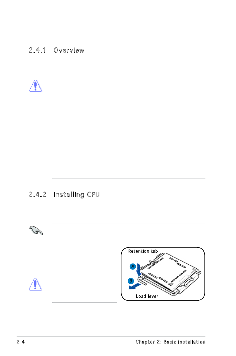
2.4 .2 Ins ta ll ing C PU
To install a CPU:
1. Locate the CPU socket on the motherboard.
Before installing the CPU, make sure that the socket box is facing
towards you and the load lever is on your left.
2. Press the load lever with your
Ret e n t ion t a b
thumb (A), then move it to the
left (B) until it is released from
the retention tab.
To prevent damage to the
socket pins, do not remove
the PnP cap unless you are
installing a CPU.
2-4 Chapter 2: Basic installation
A
B
Loa d l ever
Page 21

3. Lift the load lever in the
direction of the arrow to a 135º
angle.
PnP c a p
Loa d p late
4. Lift the load plate with your
thumb and forenger to a 100º
angle (4A), then push the PnP
cap from the load plate window
to remove (4B).
5. Position the CPU over the
socket, making sure that
the gold triangle is on the
bottom-left corner of the socket
then t the socket alignment
key into the CPU notch.
6. Close the load plate (A), then
push the load lever (B) until it
snaps into the retention tab.
4B
4A
3
CPU n o tch
Gol d
tri a n g le
mar k
Ali g n m ent k e y
A
B
2-5ASUS Pundit P3-PE5
Page 22
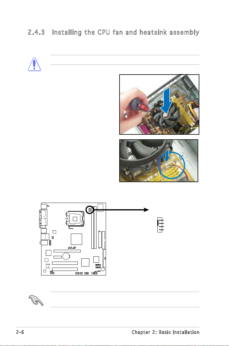
2.4 .3 Ins ta ll ing t he CP U f an a n d he a ts in k a ss em bly
R
Fan Connectors
CPU_FAN
GND
CPU FAN PWR
CPU FAN IN
CPU FAN PWM
The system package includes a proprietary CPU fan and heatsink assembly
to ensure optimum thermal condition and performance.
DO NOT replace the proprietary CPU fan and heatsink with other models!
To install the CPU fan and heatsink
assembly:
1. Place the heatsink on top of the
installed CPU.
2. Drive four screws into the fan
holes to secure the fan to the
motherboard.
3. Connect the CPU fan cable.
Refer to the gure below for the location of the CPU fan connector on
the motherboard.
Do not forget to connect the CPU fan connector! Hardware monitoring
errors can occur if you fail to plug this connector.
2-6 Chapter 2: Basic installation
Page 23
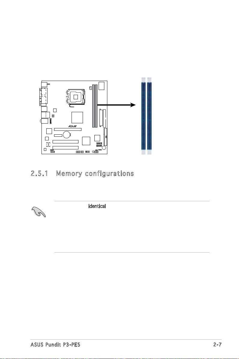
2.5 Installing a DIMM
R
240-pin DDR2 DIMM Sockets
DIMM1
DIMM2
The system motherboard comes with two Double Data Rate 2 (DDR2) Dual
Inline Memory Module (DIMM) sockets.
The following gure illustrates the location of the sockets:
2.5 .1 Mem or y con fi gu rat io ns
You may install up to 2 GB system memory using 256 MB, 512 MB, and 1
GB DDR2 DIMMs.
• Install only identical (the same type and size) DDR2 memory
modules.
• Install only ASUS-certied memory modules. Refer to the DDR2
Qualied Vendors List on the next page for details.
• Always install DIMMs with the same CAS latency. For optimum
compatibility, we recommend that you obtain memory modules from
the same vendor.
2-7ASUS Pundit P3-PE5
Page 24
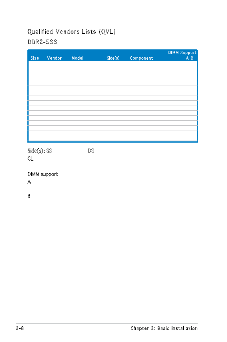
Qua l if i ed V en d ors Li s ts ( QV L )
DDR 2 -53 3
Siz e Ve n d o r Mod e l Side(s) C o m p onen t A B
DIM M S uppor t
512MB SAMSUNG K4T56083QF-GCD5 DS M378T6453FG0-CD5 V
5512MB Inneon HYB18T512800BF37 SS HYS64T64000HU-3.7-B V
1024MB Inneon HYB18T512800BF37 DS HYS64T128020HU-3.7-B V
512MB Hynix HY5PS12821AFP-C3 SS HYMP564U64AP8-C3 V
1024MB ELPIDA E5108AB-5C-E DS EBE11UD8ABFA-5C-E V
512MB CORSAIR MI110052432M8CEC DS VS512MB533D2 V
1024MB KINGMAX E5108AE-5C-E DS KLBD48F-A8EB4 V
512MB Transcend K4T51083QB-GCD5 SS TS64MLQ64V5J V
256MB Aeneon AET960UD00-37C88X SS AET560UD00-370A98X V
512MB Aeneon AET960UD00-37C88X SS AET660UD00-370A98X V
512MB Aeneon AET93F370AG0513 SS AET660UD00-370A98X V
512MB NANYA NT5TU64M8AF-37B SS NT512T64U88A0F-37B V
512MB PQI 64MX8D2-E SS MEAB-423LA V
256MB SimpleTech 858S032F25A SS SVM-42DR2/256 V
1024MB Patriot Heat-Sink Package SS PDC21G5600+XBLK V
1024MB MDT 18D51280D-3.70448 DS M924-533-16 V V
Side(s): SS - Single-sided DS - Double-sided
CL: CAS Latency
DIMM support:
A - Supports one module inserted into either slot, in Single-channel
memory conguration.
B - Supports one pair of modules inserted into both slots as one pair
of Dual-channel memory conguration.
2-8 Chapter 2: Basic installation
Page 25
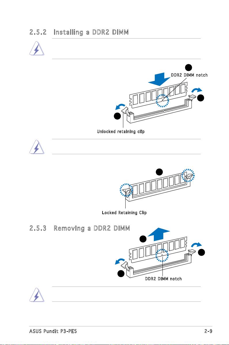
2.5 .2 Ins ta ll ing a D DR2 D IM M
Make sure to unplug the power supply before adding or removing DIMMs
or other system components. Failure to do so may cause severe damage
to both the motherboard and the components.
1. Unlock a DDR2 DIMM socket
by pressing the retaining clips
outward.
2. Align a DIMM on the socket
such that the notch on the
DIMM matches the break on
the socket.
Unl o c k ed re t a i ning c l i p
A DDR2 DIMM is keyed with a notch so that it ts in only one direction.
DO NOT force a DIMM into a socket to avoid damaging the DIMM.
1
2
DDR 2 D IMM n o t c h
1
3. Firmly insert the DIMM into the
socket until the retaining clips
snap back in place and the DIMM
is properly seated.
Loc k e d Reta i n i ng Cl i p
2.5 .3 Rem ov in g a D DR 2 D IM M
Follow these steps to remove a DIMM.
1. Simultaneously press the
retaining clips outward to
unlock the DIMM.
1
Support the DIMM lightly with your ngers when pressing the retaining
clips. The DIMM might get damaged when it ips out with extra force.
2. Remove the DIMM from the socket.
3
2
1
DDR 2 D IMM n o t c h
2-9ASUS Pundit P3-PE5
Page 26
2.6 Expansion slots
In the future, you may need to install expansion cards. The motherboard
has two PCI, one PCI Express™ x1, and one PCI Express™ x16 slot. The
following sub-sections describe the slots and the expansion cards that they
support.
The system supports low prole PCI, PCI Express x16, and PCI Express
x1 cards. You can only install low prole expansion cards on this system.
Ask your retailer for details.
2.6 .1 Exp an si on sl ot s
PCI sl o ts
The PCI slots support cards such as a LAN card, SCSI card, USB card,
andother cards that comply with PCI specications.
PCI Ex p res s x 1 6 s l ot
This motherboard supports PCI Express x16 graphic cards that comply with
the PCI Express specications. The following gure shows a graphics card
installed on the PCI Express x16 slot.
PCI Ex p res s x 1 sl o t
This motherboard supports PCI Express x1 network cards, SCSI cards and
other cards that comply with the PCI Express specications.
Before installing an expansion card, read the documentation that came
with it and make the necessary hardware settings for the card.
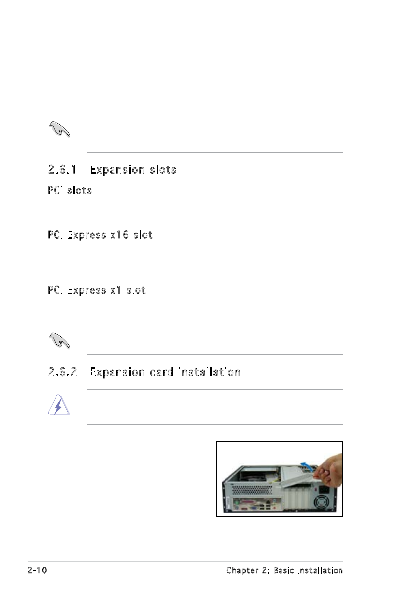
2.6 .2 Exp an si on ca rd in st al lat io n
Make sure to unplug the power cord before adding or removing
expansion cards. Failure to do so may cause you physical injury and
damage motherboard components.
To install an expansion card:
1. Lay the system on its side on a
at and stable surface.
2. Lift the expansion card lock to a
90º-100º angle.
2-10 Chapter 2: Basic installation
Page 27
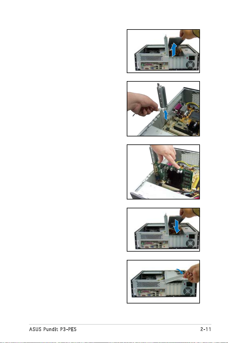
2. Remove the chassis support
bracket.
3. Remove the metal cover opposite
the slot that you intend to use.
4. Align the card connector with
the slot and press rmly until
the card is completely seated
on the slot.
5. If you have already installed a hard
disk drive, replace the chassis
support bracket; otherwise,
install other components before
replacing the chassis support
bracket.
6. Replace the expansion card lock
to secure the card to the chassis.
2-11ASUS Pundit P3-PE5
Page 28
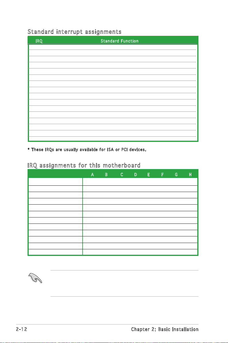
Sta n da r d i n te r rup t a s sig n me n ts
IRQ S tand a r d Func t i o n
0 System Timer
1 Keyboard Controller
2 Re-direct to IRQ#9
3 IRQ holder for PCI steering*
4 Communications Port (COM1)*
5 IRQ holder for PCI steering*
6 Floppy Disk Controller
7 Printer Port (LPT1)*
8 System CMOS/Real Time Clock
9 IRQ holder for PCI steering*
10 IRQ holder for PCI steering*
11 IRQ holder for PCI steering*
12 PS/2 Compatible Mouse Port*
13 Numeric Data Processor
14 Primary IDE Channel
15 Secondary IDE Channel
* T h e s e IRQ s a re us u a l l y av a i l a ble f o r ISA o r P CI d e v i c es.
IRQ as s ign m en t s f o r t his mo t her b oa r d
A B C D E F G H
PCI slot 1 shared — — — — — — —
PCI slot 2 — shared — — — — — —
PCI Express x 16 slot shared — — — — — — —
PCI Express x 1 slot — shared — — — — — —
Onboard USB controller 1 — — — — — — — shared
Onboard USB controller 2 — — — shared — — — —
Onboard USB controller 3 — — shared — — — — —
Onboard USB controller 4 — — — shared — — — —
Onboard USB 2.0 controller — — — — — — — shared
Onboard IDE port — — — shared — — — —
Onboard HD audio shared — — — — — — —
Onboard LAN — shared — — — — — —
When using PCI cards on shared slots, ensure that the drivers support
“Share IRQ” or that the cards do not need IRQ assignments. Otherwise,
conicts will arise between the two PCI groups, making the system
unstable and the card inoperable.
2-12 Chapter 2: Basic installation
Page 29
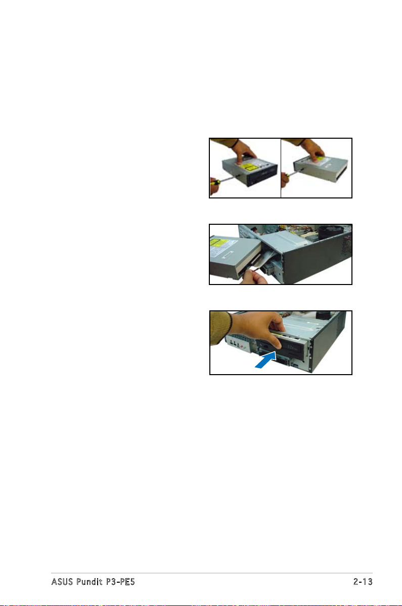
2.7 Installing an optical drive
Refer to the instructions in this section if you wish to install a new optical
drive.
Follow these steps to install an optical drive:
1. Drive a screw on the top right
screw hole on both sides of
the drive.
2. Connect the IDE and audio
cable at the back of the drive.
3. Push the drive all the way into
the bay until the drive lock clicks.
4. Connect a 4-pin power plug
from the power supply unit to
the power connector at the
back of the drive.
2-13ASUS Pundit P3-PE5
Page 30

Uni ns ta lli ng t he op ti cal d ri ve
In the future, you may have to upgrade or replace a defective optical drive.
To uninstall the optical drive:
1. Remove the front panel assembly following the instructions in section.
2. Locate the optical drive screw lock.
3. Push the lock to release the
optical drive screw (A), then
slightly pull the drive out from
the bay (B).
4. Disconnect the IDE, audio, and
power cables and plugs from the
back of the drive.
5. Pull out the drive completely
from the bay, then replace it
following the instructions in the
previous section.
A
B
2-14 Chapter 2: Basic installation
Page 31

2.8 Removing the card reader
In the future, you may have to remove or replace the 6-in-1 card reader.
To uninstall the card reader:
1. Remove the front panel assembly following the instructions in “2.3.2
Removing the front panel assembly”.
2. Locate the lock on both sides of
the card reader assembly.
3. Press the card reader lock
inwards(A), then slightly pull the
card reader assembly outward
(B) until the USB cable and plug
is exposed.
4. Disconnect the USB cable and
plug from the card reader
assembly, then set the card
reader assembly aside.
A
B
2-15ASUS Pundit P3-PE5
Page 32

2.9 Installing hard disk drives (HDDs)
The system comes with two 3.5-inch drive bays (labeled 1 and 2) for
installation of two Serial ATA hard disk drives or one IDE HDD (if you have
installed an optical drive).
2.9 .1 Har d di sk dr iv e b ay s
The drive bays incorporate a
screw-less design that allows you
to install and remove a hard disk
drive without driving screws on the
chassis. Each drive bay has a HDD
screw lock and four screws rails (two
on each side of the bay) that trap
the HDD screws and secure the drive
in the place.
HDD s c rew l o c k
When installing one hard disk drive, install it on the upper HDD bay.
2.9 .2 SAT A ha rd di sk dr iv e ins ta ll ati on
To install a SATA hard disk drive:
Scr e w rails
1
2
Scr e w rails
1. Insert the rubber washers to
the HDD screws. Refer to the
illustration on the right.
Rubber washer mat
1
2. Drive four screws (two on
each side of the drive) on the
drive screw holes.
2
2-16 Chapter 2: Basic installation
Rub b e r wash e r
2
Page 33

3. Connect one end of the
supplied 7-pin SATA cable
to the SATA connector at
the back of the drive, then
connect the other end to
a SATA connector on the
motherboard. See page 4-7
for the location of the SATA
connectors.
4. Connect the 15-pin SATA power
plug from the power supply unit
to the power connector at the
back of the drive.
5. Place the HDD on the tray.
Make sure that the HDD
screws are aligned with the
screw holes and rails.
6. When the HDD screws align
with the screw rails, push
the drive carefully until it is
completely ushed on the bay.
The HDD screw lock clicks
to indicate that the drive is
properly in place.
HDD s c rew l o c k
2-17ASUS Pundit P3-PE5
Page 34

2.9 .3 IDE h ar d d is k dri ve i nst al la tio n
Set the IDE HDD as master device before connecting the IDE cable and
power plug. Refer to the HDD documentation for details.
To install an IDE hard disk drive:
1. Follow steps 1 to 2 of the previous section.
2. Connect the IDE cable (gray connector) to the IDE interface at the
back of the drive. Match the red stripe on the cable with Pin 1 on the
IDE interface.
3. Connect a power cable from the power supply unit to the power
connector at the back of the drive.
4. Follow steps 5 to 6 of the previous section to complete installation.
2.9 .4 Uni ns ta lli ng a ha rd d isk d ri ve
In the future, you may have to upgrade or replace a defective hard disk
drive.
To uninstall the hard disk drive:
1. Press the HDD screw lock (A),
then push the drive out from
the bay (B) until the drive
screws are released from the
screw rails.
B
A
2. Slightly lift the HDD, then
remove all plugs at the back of
the drive.
3. Install a new HDD following the
instructions in the previous
section.
2-18 Chapter 2: Basic installation
Page 35

2.10 Replacing the covers
After you install all the necessary components on the system, replace the
covers following the instructions in this section:
2.1 0. 1 R ep la c in g th e f ro nt pa ne l a ss em bl y
To replace the front panel assembly:
1. Hook the hinge-like tabs to the holes on the right side of the chassis.
Hin g e - like t a b s
2. Swing the left edge of the front panel inward, then attach the front
panel assembly hooks to the chassis until they snap in place.
Do not use too much force when replacing the front panel assembly.
2-19ASUS Pundit P3-PE5
Page 36

2.1 0. 2 R ep la c in g th e s ys te m c ov er
To replace the metal chassis support:
1. Reinstall the metal chassis
support and the expansion
card lock.
2. Match and insert the hooks
of the cover to the elongated
holes on the side of the
chassis. All eight hooks (four
hooks on both sides) of the
cover must properly t the
designated holes.
3. Slide the cover toward the front
panel until it is in place.
4. Replace the cover screws.
2-20 Chapter 2: Basic installation
Page 37

2.11 Installing the foot stands
You need to install the foot stands to place the system vertically on your
desktop.To install the foot stands:
1. Lay the system on its side on a
at, stable, and elevated surface,
then locate two screw holes on
the left side of the system.
2. Extend the left side of the
system at least 3 cm from the
edge of the surface to facilitate
installation.
3. Align the foot stand and chassis
screw holes.
4. Drive in a screw to secure the
footstand to the chassis.
5. Follow the same procedures when
installing the second foot stand.
The photo on the right shows
the system in a vertical desktop
placement.
2-21ASUS Pundit P3-PE5
Page 38

Chapter 3
This chapter helps you power up
the system and install drivers and
utilities from the support CD.
ASUS Pundit P3-PE5
Starting up
Page 39

3.1 Installing an operating system
The barebone system supports Windows® 2000/XP operating systems
(OS). Always install the latest OS version and corresponding updates so
you can maximize the features of your hardware.
Because motherboard settings and hardware options vary, use the setup
procedures presented in this chapter for general reference only. Refer to
your OS documentation for more information.
3.2 Powering up
Press the system power button ( ) to enter the OS.
Pre s s to tu r n ON th e s y stem
3.3 Support CD information
The support CD that came with the system contains useful software and
several utility drivers that enhance the system features.
•
Screen display and driver options may not be the same for different
operating system versions.
•
The contents of the support CD are subject to change at any time
without notice. Visit the ASUS website for updates.
3-2 Chapter 3: Starting up
Page 40

3.3 .1 Run ni ng th e su ppo rt C D
To begin using the support CD, place the CD in your optical drive. The
CD automatically displays the Drivers menu if Autorun is enabled in your
computer.
Cli c k an ic o n to
dis p l a y sup p o r t
CD/ m o t herbo a r d
inf o r m ation
Cli c k an it e m to in s t a ll
If Autorun is NOT enabled in your computer, browse the contents of the
support CD to locate the le ASSETUP.EXE from the BIN folder.
Double-click the ASSETUP.EXE to run the CD.
ASU S I n stA l l - In s ta l lat i on Wiz a rd for Dr i ver s
Automatically installs all the necessary drivers for this motherboard.
VIA 4 i n 1 Dri ver s
Installs the VIA 4 in 1 drivers.
VIA / S3 G Un i Chr ome Fam ily Dis pla y Dr ive r
Installs the VIA/S3G Unichrome Family Display driver.
Sou n dM A X A D 198 6A A udi o D r ive r
Allows you to install the SoundMAX AD1986A audio driver.
JMo c ro n JM B 36X RA I D C ont r oll er D riv er
Installs the JMocron JMB36X RAID Controller Driver.
VIA Rh i ne F am i ly F as t Et h er n et A da p ter Dr i ver
Installs the VIA Rhine Family FAst Ethernet Adapter driver.
3-3ASUS Pundit P3-PE5
Page 41

3.3 .2 Uti li ti es me nu
The Utilities menu shows the applications and other software that the
motherboard supports.
ASU S I n stA l l- I nst a ll a tio n W i zar d f o r U t ili tie s
Installs the ASUS InstAll-Installation Wizard Utilities.
ASU S P C Pr o be II
This smart utility monitors the fan speed, CPU temperature, and system
voltages, and alerts you of any detected problems. This utility helps you keep
your computer in healthy operating condition.
ASU S U p dat e
The ASUS Update utility allows you to update the motherboard BIOS in a
Windows® environment. This utility requires an Internet connection either through
a network or an Internet Service Provider (ISP). See page 5-8 for details.
ASU S S c ree n S a ver
Installs the ASUS screen saver.
Ado b e R ead e r V 7.0
Installs the Adobe® Acrobat® Reader V7.0 that allows you to open, view, and
print documents in Portable Document Format (PDF).
Mic r os o ft D ir e ctX 9. 0 c D r ive r
Installs the Microsoft® DirectX 9.0c driver.
3-4 Chapter 3: Starting up
Page 42

3.3 .3 Mak e Di sk
VIA RA I D D r iv e r D i sk
Creates the VIA RAID driver disk.
Mak e J M icr o n J MB3 6 X 3 2/6 4 bit RA I D D r iv e r
Creates the JMicron JMB36X 32/64bit RAID driver disk.
3.3 .4 ASU S Co nta ct i nfo rm at ion
Click the Contact tab to display the ASUS contact information. You can also
nd this information on the inside front cover of this user guide.
3-5ASUS Pundit P3-PE5
Page 43

3.4 Software information
Most of the applications in the support CD have wizards that will
conveniently guide you through the installation. View the online help or
readme le that came with the software for more information.
ASU S PC Pr ob e II
PC Probe II is a utility that monitors the computer’s vital components
and alerts you of any problem with these components. PC Probe II senses
fan rotations, CPU temperature, and system voltages, among others. PC
Probe II is software-based, allowing you to start monitoring your computer
the moment you turn it on. With this utility, you are assured that your
computer is always at a healthy operating condition.
Ins t al l ing PC Pro b e I I
To install PC Probe II on your computer:
1. Place the support CD to the optical drive. The
appears if your computer has an enabled Autorun feature.
If Autorun is not enabled in your computer, browse the contents of the
support CD to locate the setup.exe le from the ASUS PC Probe II folder.
Double-click the setup.exe le to start installation.
2. Click the Utilities tab, then click ASUS PC Probe II.
3. Follow the screen instructions to complete installation.
Drivers installation tab
Lau n ch i ng P C P rob e I I
You can launch the PC Probe II right after installation or anytime from the
Windows® desktop.
To launch the PC Probe II from the Windows® desktop, click Start > All
Programs > ASUS > PC Probe II. The PC Probe II main window appears.
After launching the application, the PC Probe II icon appears in the
Windows® taskbar. Click this icon to
close or restore the application.
Usi n g P C P r ob e II
Main window
The PC Probe II main window allows
you to view the current status of
your system and change the utility
conguration. By default, the main window displays the Preference section.
You can close or restore the Preference section by clicking on the triangle on
the main window right handle.
Cli c k to cl o s e the
Pre f e r ence p a n el
3-6 Chapter 3: Starting up
Page 44

But t o n F u nctio n
Opens the Conguration window
Opens the
Opens the
Opens the
Opens the
Opens the hard disk drive, memory, CPU usage window
Shows/Hides the
Minimizes the application
Closes the application
Report window
Desktop Management Interface window
Peripheral Component Interconnect window
Windows Management Instrumentation window
Preference section
Sensor alert
When a system sensor detects a problem, the main window right handle
turns red, as the illustrations below show.
When displayed, the monitor panel for that sensor also turns red. Refer to
the Monitor panels section for details.
Pre f er e nce s
You can customize the application using the
Preference section in the main window. Click
the box before each preference to activate or
deactivate.
3-7ASUS Pundit P3-PE5
Page 45

Har d wa r e m o ni t or p an e ls
The hardware monitor panels display the current value of a system sensor
such as fan rotation, CPU temperature, and voltages.
The hardware monitor panels come in two display modes: hexagonal (large)
and rectangular (small). When you check the Enable Monitoring Panel
option from the Preference section, the monitor panels appear on your
computer’s desktop.
Sma l l displ a y
Lar g e displ a y
Changing the monitor panels position
To change the position of the monitor panels on the desktop,
click the arrow down button of the Scheme options, then
select another position from the list box. Click OK when
nished.
Moving the monitor panels
All monitor panels move together using
a magnetic effect. If you want to detach
a monitor panel from the group, click the
horseshoe magnet icon. You can now move
or reposition the panel independently.
Adjusting the sensor threshold value
You can adjust the sensor threshold
value in the monitor panel by clicking
the arrow buttons. You can also
adjust the threshold values using the
Cong window.
You cannot adjust the sensor threshold
values in a small monitoring panel.
Cli c k to
inc r e a se
val u e
Cli c k to
dec r e a se
val u e
3-8 Chapter 3: Starting up
Page 46

Monitoring sensor alert
The monitor panel turns red when a component value exceeds or is lower
than the threshold value. Refer to the illustrations below.
Sma l l displ a y
Lar g e displ a y
WMI br o wse r
Click to display the
WMI (Windows Management
Instrumentation) browser. This
browser displays various Windows®
management information. Click an
item from the left panel to display
on the right panel. Click the plus
sign (+) before WMI Information to
display the available information.
You can enlarge or reduce the browser size by dragging the bottom right
corner of the browser.
DMI br o wse r
Click to display the DMI
(Desktop Management Interface)
browser. This browser displays
various desktop and system
information. Click the plus sign (+)
before DMI Information to display
the available information.
3-9ASUS Pundit P3-PE5
Page 47

PCI br o wse r
Click to display the
PCI (Peripheral Component
Interconnect) browser. This
browser provides information on
the PCI devices installed on your
system. Click the plus sign (+)
before the PCI Information item to
display available information.
Usa g e
The Usage browser displays real-time information on the CPU, hard disk
drive space, and memory usage. Click to display the Usage browser.
CPU usage
The CPU tab displays real-time CPU
usage in line graph representation.
If the CPU has an enabled HyperThreading, two separate line graphs
display the operation of the two
logical processors.
Hard disk drive space usage
The Hard Disk tab displays the used
and available hard disk drive space.
The left panel of the tab lists all
logical drives. Click a hard disk drive
to display the information on the
right panel. The pie chart at the
bottom of the window represents
the used (blue) and the available
HDD space.
3-10 Chapter 3: Starting up
Page 48

Memory usage
The Memory tab shows both used
and available physical memory.
The pie chart at the bottom of the
window represents the used (blue)
and the available physical memory.
Con f ig u rin g P C Pr o be II
Click to view and adjust the sensor threshold values.
The Cong window has two tabs: Sensor/Threshold and Preference. The
Sensor/Threshold tab enables you to activate the sensors or to adjust the
sensor threshold values. The Preference tab allows you to customize sensor
alerts, change temperature scale, or enable the Q-Fan feature.
Loa d s the d e f a u lt
thr e s h old v a l u es
for e a ch se n s o r
App l i e s you r
cha n g e s
Can c e l s or
ign o r e s you r
cha n g e s
Lo ads y our s ave d
co nfigu ratio n
Sav e s your
con f i g urati o n
3-11ASUS Pundit P3-PE5
Page 49

Chapter 4
This chapter gives information
about the motherboard that comes
with the system. This chapter
includes the motherboard layout,
jumper settings, and connector
locations.
ASUS Pundit P3-PE5
Motherboard info
Page 50

LGA775
DDR2 DIMM1 (128 bit,240-pin module)
DDR2 DIMM2 (128 bit,240-pin module)
VIA
P4M890
VIA
8237A
4Mb
BIOS
PCIEX16
PCIEX1
PCI1
PCI2
CR2032 3V
Lithium Cell
CMOS Power
SEC_IDE
PRI_IDE
FLOPPY
SATA2
SATA1
CD AUX
AAFP
USB56
USB78
CHA_FAN
CPU_FAN
Super I/O
EATXPWR
ATX12V
SATA_A
BUZZER
CLRTC
CHASSIS
USBPW56
USBPW78
USBPW56
USBPW78
SPDIF_OUT
KBPWR
SB_PWR
F_PANEL
ADI1986A
RTL8201CL
JMB363
Below:Mic In
Center:Line Out
To p:Line In
USB12
RJ-45
Top:
USB3
USB4
Bottom:
R
PS/2KBMS
T: Mouse
B: Keyboard
VGA
ESATA
PARALLEL PORT
21.8cm (8.6in)
24.5cm (9.6in)
4.1 Introduction
The Pundit P3-PE5 barebone system comes with an ASUS motherboard.
This chapter provides technical information about the motherboard for
future upgrades or system reconguration.
4.2 Motherboard layout
4-2 Ch a p t e r 4 : M o t h e r b o a r d i n f o
Page 51

4.3 Jumpers
R
Clear RTC RAM
CLRTC
Normal Clear CMOS
(Default)
2 31 2
1. Clea r R TC R A M (CLR T C )
This jumper allows you to clear the Real Time Clock (RTC) RAM in
CMOS. You can clear the CMOS memory of date, time, and system
setup parameters by erasing the CMOS RTC RAM data. The onboard
button cell battery powers the RAM data in the CMOS, which includes
the system setup information such as system passwords.
To erase the RTC RAM:
1. Turn OFF the computer and unplug the power cord.
2. Remove the battery.
3. Move the jumper cap from pins 1-2 (default) to pins 2-3. Keep
the cap on pins 2-3 for about 5-10 seconds, then move the cap
back to pins 1-2.
4. Re-install the battery.
5. Plug the power cord and turn ON the computer.
6. Hold down the <Del> key during the boot process and enter BIOS
setup to re-enter data.
Except when clearing the RTC RAM, never remove the cap on CLRTC
jumper default position. Removing the cap will cause system boot failure.
4-3ASUS Pundit P3-PE5
Page 52

2. USB d e v ice w a k e-up ( 3 -pin U S BPW1 2 , U SBPW 3 4 , USB P W 5 6,
R
USB Device Wake Up
3
2
2
1
USBPW12
USBPW34
+5V
(Default)
+5VSB
3
2
2
1
USBPW56
USBPW78
+5V
(Default)
+5VSB
USBP W 7 8 )
Set these jumpers to +5V to wake up the computer from S1 sleep
mode (CPU stopped, DRAM refreshed, system running in low power
mode) using the connected USB devices. Set to +5VSB to wake up
from S3 and S4 sleep modes (no power to CPU, DRAM in slow refresh,
power supply in reduced power mode).
The USBPWR12 and USBPWR34 jumpers are for the rear USB ports.
The USBPWR56 and USBPWR78 jumper is for the internal USB
connectors that you can connect to additional USB ports.
• The USB device wake-up feature requires a power supply that can
provide 500mA on the +5VSB lead for each USB port; otherwise,
the system would not power up.
• The total current consumed must NOT exceed the power supply
capability (+5VSB) whether under normal condition or in sleep mode.
4-4 Ch a p t e r 4 : M o t h e r b o a r d i n f o
Page 53

3. Keyb o a r d po w e r (3- p i n KBP W R )
R
Keyboard Power Setting
(Default)
+5V +5VSB
KBPWR
2 31 2
This jumper allows you to enable or disable the keyboard wake-up
feature. Set this jumper to pins 2-3 (+5VSB) if you wish to wake up
the computer when you press a key on the keyboard (the default is
the Space Bar). This feature requires an ATX power supply that can
supply at least 1A on the +5VSB lead, and a corresponding setting in
the BIOS.
4-5ASUS Pundit P3-PE5
Page 54

R
SATA_A Connector
SATA_A
GND
RSATA_TXP1
RSATA_TXN1
GND
RSATA_RXP1
RSATA_RXN1
GND
4.4 Connectors
R
SATA Connectors
SATA2
GND
GND
GND
RSATA_RXN2
RSATA_TXN2
RSATA_TXN2
RSATA_RXP2
SATA1
GND
RSATA_TXP1
RSATA_TXN1
GND
RSATA_RXP1
RSATA_RXN1
GND
1. Seri a l ATA c o n nect o r s 1&2 ( 7 -pin S A TA1, S A T A2 [ B l a ck])
These connectors are for the Serial ATA signal cables for Serial ATA
hard disk drives.
Important notes on Serial ATA:
• You must install Windows
®
2000 Service Pack 4 or the Windows® XP
Service Pack1 before using Serial ATA hard disk drives.
• When using the connectors in
Standard IDE mode, connect the primary
(boot) hard disk drive to the SATA1 or SATA2 connector.
Ser i a l ATA c o nnec t o r A ( 7 - p in S A T A _A [ R E D ])
4-6 Ch a p t e r 4 : M o t h e r b o a r d i n f o
Page 55

2 ID E co n n e ctor s ( 40-1 p i n PR I _ I DE, S E C _IDE )
R
IDE Connectors
NOTE: Orient the red markings
(usually zigzag) on the ID
ribbon cable to PIN 1.
SEC_IDE
PRI_IDE
The onboard IDE connectors are for Ultra DMA 133/100/66 signal
cable(s). There are three connectors on each Ultra DMA 133/100/66
signal cable: blue, black, and gray. Connect the blue connector to
the motherboard’s IDE connector, then select one of the following
modes to congure your device(s).
Drive jumper
setting
Single device Cable-Select or
Master
Two devices Cable-Select Master
Master
Slave
Mode Cable of
device(s)
- Black
Slave
Master
Slave
Cable connector
Black
Gray
Black or gray
• Pin 20 on the IDE connector is removed to match the covered hole
on the Ultra DMA cable connector. This prevents incorrect insertion
when you connect the IDE cable.
• Use the 80-conductor IDE cable for Ultra DMA 133/100/66 IDE
devices.
If any device jumper is set as “Cable-Select”, make sure all other device
jumpers have the same setting.
4-7ASUS Pundit P3-PE5
Page 56

4. CPU F a n con n e c tor ( 4 - pin C P U _FAN )
R
Fan Connectors
CPU_FAN
GND
CPU FAN PWR
CPU FAN IN
CPU FAN PWM
R
USB2.0 Connectors
USB78
USB+5V
USB_P8-
USB_P8+
GND
NC
USB+5V
USB_P7-
USB_P7+
GND
1
USB56
USB+5V
USB_P6-
USB_P6+
GND
NC
USB+5V
USB_P5-
USB_P5+
GND
1
The fan connector support cooling fans of 350 mA~740 mA (8.88 W
max.) or a total of 1 A~2.22 A (26.64 W max.) at +12V. Connect the
fan cable to the fan connector on the motherboard, making sure that
the black wire of each cable matches the ground pin of the connector.
Do not forget to connect the fan cables to the fan connectors.
Insufcient air ow inside the system may damage the motherboard
components. These are not jumpers! Do not place jumper caps on the
fan connectors!
5. USB c o n nect o r s (10 - 1 p in U S B 5 6, U S B 7 8)
These connectors are for USB 2.0 ports. Connect the USB/GAME
module cable to any of these connectors, then install the module to a
slot opening at the back of the system chassis. These USB connectors
comply with USB 2.0 specication that supports up to 480 Mbps
connection speed.
Never connect a 1394 cable to the USB connectors. Doing so will
damage the motherboard!
4-8 Ch a p t e r 4 : M o t h e r b o a r d i n f o
The USB module is purchased separately.
Page 57

6. ATX p o w er c o n n ecto r s (24- p i n EAT X P W R, 4 - p i n AT X 1 2 V )
R
ATX Power Connector
+3 Volts
+3 Volts
Ground
+5 Volts
+5 Volts
Ground
Ground
Power O
+5V Standby
+12 Volts
-5 Volts
+5 Volts
+3 Volts
-12 Volts
Ground
Ground
Ground
PSON#
Ground
+5 Volts
+12 Volts
+3 Volts
+5 Volts
Ground
GND
GND
ATX12V
EATXPWR
+12VDC +12VDC
R
Internal Audio Connectors
AUX
(White)
Right Audio Channel
Left Audio Channel
Ground
Ground
CD
(black)
Right Audio Channel
Left Audio Channel
Ground
Ground
These connectors are for ATX power supply plugs. The plugs from
the power supply are designed to t these connectors in only one
orientation. Find the proper orientation and push down rmly until the
connectors completely t.
•
Do not forget to connect the 4-pin ATX +12 V power plug;
otherwise, the system will not boot.
• Use of a PSU with a higher power output is recommended when
conguring a system with more power-consuming devices. The
system may become unstable or may not boot up if the power is
inadequate.
• Make sure that your power supply unit (PSU) can provide at least
the minimum power required by your system.
7. Inte r n a l au d i o con n e c tors ( 4 -pin C D , 4- p i n AUX )
These connectors allow you to receive stereo audio input from sound
sources such as a CD-ROM, TV tuner, or MPEG card.
Enable the CD-IN function in the audio utility when using this connector.
4-9ASUS Pundit P3-PE5
Page 58

8. Fron t p anel a u dio c o n nect o r (10- 1 p in A A F P )
R
Digital Audio Connector
+5V
SPDIFOUT
GND
SPDIF_OUT
R
Azalia Analog Front Panel Connector
HP_HD
MIC2_L
HP_R
HP_L
MIC2_JD
Jack_Sense
MIC2_R
PRESENSE#
AGND
AAFP
This connector is for a chassis-mounted front panel audio I/O module
that supports HD Audio standard.
We recommend that you connect a high-denition front panel audio
module to this connector to avail of the motherboard’s high-denition
audio capability.
9. Digi t a l aud i o conn e c t or ( 4 - 1 pin S P DIF_ O U T )
This connector is for an additional Sony/Philips Digital Interface
(S/PDIF) port(s). Connect the S/PDIF module cable to this connector,
then install the module to a slot opening at the back of the system
chassis.
The S/PDIF module is purchased separately.
4-10 Ch a p t e r 4 : M o t h e r b o a r d i n f o
Page 59

10. C h a ssis i n trus i o n con n e c tor ( 4 - 1 pi n C HASS I S )
R
Chassis Intrusion Connector
CHASSIS
+5VSB_MB
Chassis Signal
GND
(Default)
This connector is for a chassis-mounted intrusion detection sensor
or switch. Connect one end of the chassis intrusion sensor or switch
cable to this connector. The chassis intrusion sensor or switch sends
a high-level signal to this connector when a chassis component
is removed or replaced. The signal is then generated as a chassis
intrusion event.
By default, the pins labeled “Chassis Signal” and “Ground” are shorted
with a jumper cap. Remove the jumper cap only when you intend to
use the chassis intrusion detection feature.
4-11ASUS Pundit P3-PE5
Page 60

12. S y s tem p a n el c o n n ecto r ( 10-1 p i n F_ P A N EL)
R
System Panel Connector
F_PANEL
PLED-
PWR
PLED+
Ground
GNDReset
IDELED+
IDELED-
HD LED RESET
PLED PWRSW
This connector supports several chassis-mounted functions.
The sytem panel connector is color-coded for easy connection. Refer to
the connector description below for details.
•
System power LED (2-pin PLED)
This 3-pin connector is for the system power LED. Connect the
chassis power LED cable to this connector. The system power LED
lights up when you turn on the system power, and blinks when the
system is in sleep mode.
• Hard disk drive activity (2-pin HDLED)
This 2-pin connector is for the HDD Activity LED. Connect the HDD
Activity LED cable to this connector. The IDE LED lights up or ashes
when data is read from or written to the HDD.
• Power/Soft-off button (2-pin PWRSW)
This connector is for the system power button. Pressing the power
button turns the system ON or puts the system in SLEEP or SOFT-OFF
mode depending on the BIOS settings. Pressing the power switch for
more than four seconds while the system is ON turns the system OFF.
• Reset button (2-pin RESET)
This 2-pin connector is for the chassis-mounted reset button for
system reboot without turning off the system power.
4-12 Ch a p t e r 4 : M o t h e r b o a r d i n f o
Page 61

Chapter 5
This chapter tells how to change
system settings through the BIOS
Setup menus and describes the
BIOS parameters.
ASUS Pundit P3-PE5
BIOS setup
1
Page 62

5.1 Managing and updating your BIOS
The following utilities allow you to manage and update the motherboard
Basic Input/Output System (BIOS) setup.
1.
ASUS Update (Updates the BIOS in Windows® environment)
ASUS EZ Flash (Updates the BIOS during the Power-On Self Test)
2.
Award BIOS Flash Utility (Updates the BIOS in DOS mode)
3.
ASUS CrashFree BIOS 2 (Updates the BIOS when the BIOS le fails or
4.
gets corrupted.)
Refer to the corresponding sections for details on these utilities.
Save a copy of the original motherboard BIOS le to a bootable oppy
disk in case you need to restore the BIOS in the future. Copy the original
motherboard BIOS using the ASUS Update or Award BIOS Flash utilities.
5.1 .1 ASU S Up dat e ut ili ty
The ASUS Update is a utility that allows you to manage, save, and update
the motherboard BIOS in Windows® environment. The ASUS Update utility
allows you to:
• Save the current BIOS le
• Download the latest BIOS le from the Internet
• Update the BIOS from an updated BIOS le
• Update the BIOS directly from the Internet, and
• View the BIOS version information.
This utility is available in the support CD that comes with the motherboard
package.
ASUS Update requires an Internet connection either through a network
or an Internet Service Provider (ISP).
Ins t al l ing AS U S U p dat e
To install ASUS Update:
1. Place the support CD in the optical drive. The Drivers menu appears.
2. Click the Utilities tab, then click Install ASUS Update VX.XX.XX.
3. The ASUS Update utility is copied to your system.
Quit all Windows® applications before you update the BIOS using this
utility.
5-2 Chapter 5: BIOS setup
Page 63

Upd a ti n g t h e B IOS th r oug h t h e I n te r net
To update the BIOS through the Internet:
1. Launch the ASUS Update utility from the Windows
Start > Programs > ASUS > ASUSUpdate > ASUSUpdate. The ASUS
Update main window appears.
®
desktop by clicking
2. Select Update BIOS from
the Internet option from the
drop-down menu, then click
Next.
3. Select the ASUS FTP site
nearest you to avoid network
trafc, or click Auto Select.
Click Next.
5-3ASUS Pundit P3-PE5
Page 64

4. From the FTP site, select the
BIOS version that you wish to
download. Click Next.
5. Follow the screen instructions to
complete the update process.
The ASUS Update utility is
capable of updating itself
through the Internet. Always
update the utility to avail all
its features.
Upd a ti n g t h e B IOS th r oug h a BIO S f i le
To update the BIOS through a BIOS le:
1. Launch the ASUS Update utility from the Windows
clicking Start > Programs > ASUS > ASUSUpdate > ASUSUpdate. The
ASUS Update main window appears.
2. Select Update BIOS from a le
option from the drop-down menu,
then click Next.
®
desktop by
3. Locate the BIOS le from the
Open window, then click Open.
4. Follow the screen instructions to
complete the update process.
5-4 Chapter 5: BIOS setup
Page 65

5.1 .2 Cre at in g a b oo tab le f lop py d isk
1. Do either one of the following to create a bootable oppy disk.
DOS environment
a. Insert a 1.44MB oppy disk into the drive.
format
b. At the DOS prompt, type
Windows® XP environment
a. Insert a 1.44 MB oppy disk to the oppy disk drive.
b. Click
Start from the Windows® desktop, then select My Computer.
c. Select the 3 1/2 Floppy Drive icon.
d. Click File from the menu, then select
Floppy Disk window appears.
e. Select
Create an MS-DOS startup disk from the format options
eld, then click Start.
Windows® 2000 environment
To create a set of boot disks for Windows
a. Insert a formatted, high density 1.44 MB oppy disk into the drive.
®
b. Insert the Windows
c. Click
Start, then select Run.
2000 CD to the optical drive.
d. From the Open eld, type
D:\bootdisk\makeboot a:
assuming that D: is your optical drive.
e. Press <Enter>, then follow screen instructions to continue.
A:/S then press <Enter>.
Format. A Format 3 1/2
®
2000:
2. Copy the original or the latest motherboard BIOS le to the bootable
oppy disk.
5-5ASUS Pundit P3-PE5
Page 66

5.1 .3 ASU S EZ Fl as h uti li ty
The ASUS EZ Flash feature allows you to update the BIOS without having
to go through the long process of booting from a oppy disk and using
a DOS-based utility. The EZ Flash utility is built-in the BIOS chip so it is
accessible by pressing <Alt> + <F2> during the Power-On Self Tests
(POST).
To update the BIOS using EZ Flash 2:
1. Download the latest BIOS le from ASUS website (www.asus.com), or
obtain it from the support CD.
2. Save the BIOS le to a oppy disk, then boot the system from oppy
disk.
3. Press <Alt> + <F2> during POST, the following screen appears:
EZFlash starting BIOS update
Checking for oppy...
4. Insert the oppy disk that contains the BIOS le to the oppy disk
drive. When the correct BIOS le is found, EZ Flash performs the BIOS
update process and automatically reboots the system when done.
Do not shut down or reset the system while updating the BIOS to
prevent system boot failure!
5-6 Chapter 5: BIOS setup
Page 67

5.1 .4 Awa rd BI OS Fl as h U ti li ty
The Basic Input/Output System (BIOS) can be updated using the
AwardBIOS Flash Utility. Follow these instructions to update the BIOS using
this utility.
1. Download the latest BIOS le from the ASUS web site. Rename the le
to P5VD2MX.BIN and save it to a oppy disk.
Save only the updated BIOS le in the oppy disk to avoid loading the
wrong BIOS le.
2. Copy the AwardBIOS Flash Utility (awdash.exe) from the Software
folder of the support CD to the oppy disk with the latest BIOS le.
3. Boot the system in DOS mode using the bootable oppy disk you
created earlier.
4. When the A:> appears, replace the bootable oppy disk with the
oppy disk containing the new BIOS le and the Award BIOS Flash
Utility.
5. At the prompt, type
awdash then press
<Enter>. The Award
BIOS Flash Utility
screen appears.
AwardBIOS Flash Utility for ASUS V1.17
(C) Phoenix Technologies Ltd. All Rights Reserved
For P4M890-8237A-P5VD2-MX DATE:05/04/2006
Flash Type - SST 49LF004B LPC (4MB)
File Name to Program: P5VD2MX.bin
6. Type the BIOS le
name in the File Name
to Program eld, then
press <Enter>.
Message: Please input File Name!
AwardBIOS Flash Utility for ASUS V1.17
(C) Phoenix Technologies Ltd. All Rights Reserved
For P4M890-8237A-P5VD2-MX DATE:05/04/2006
Flash Type - SST 49LF004B LPC (4MB)
File Name to Program: P5VD2MX.bin
Message: Do You Want To Save Bios (Y/N)
5-7ASUS Pundit P3-PE5
Page 68

7. Press <N> when the utility prompts you to save the current BIOS le.
The following screen appears.
8. The utility veries the
BIOS le in the oppy
disk and starts ashing
the BIOS le.
Do not turn off or reset the system during the ashing process!
AwardBIOS Flash Utility for ASUS V1.17
(C) Phoenix Technologies Ltd. All Rights Reserved
For P4M890-8237A-P5VD2-MX DATE:05/04/2006
Flash Type - SST 49LF004B LPC (4MB)
File Name to Program: P5VD2MX.bin
Programming Flash Memory - OFE00 OK
Write OK No Update Write Fail
Warning: Don’t Turn Off Power Or Reset System!
9. The utility displays
a Flashing Complete
message indicating that
you have successfully
ashed the BIOS le.
Remove the oppy disk
then press <F1> to
restart the system.
AwardBIOS Flash Utility for ASUS V1.17
(C) Phoenix Technologies Ltd. All Rights Reserved
For P4M890-8237A-P5VD2-MX DATE:05/04/2006
Flash Type - SST 49LF004B LPC (4MB)
File Name to Program: P5VD2MX.bin
Flashing Complete
Press <F1> to Continue
Write OK No Update Write Fail
F1
Reset
5-8 Chapter 5: BIOS setup
Page 69

5.1 .5 Sav in g the c ur ren t BI OS fi le
You can use the AwardBIOS Flash Utility to save the current BIOS le. You
can load the current BIOS le when the BIOS le gets corrupted during the
ashing process.
Make sure that the oppy disk has enough disk space to save the le.
To save the current BIOS le using the AwardBIOS Flash Utility:
1. Follow steps 1 to 6 of
the previous section.
2. Press <Y> when the
utility prompts you to
save the current BIOS
le. The following screen
appears.
3. Type a lename for
the current BIOS le in
the Save current BIOS
as eld, then press
<Enter>.
4. The utility saves the
current BIOS le to the
oppy disk, then returns
to the BIOS ashing
process.
AwardBIOS Flash Utility for ASUS V1.17
(C) Phoenix Technologies Ltd. All Rights Reserved
For P4M890-8237A-P5VD2-MX DATE:05/04/2006
Flash Type - SST 49LF004B LPC (4MB)
File Name to Program: P5VD2MX.bin
Save current BIOS as:
Message:
AwardBIOS Flash Utility for ASUS V1.17
(C) Phoenix Technologies Ltd. All Rights Reserved
For P4M890-8237A-P5VD2-MX DATE:05/04/2006
Flash Type - SST 49LF004B LPC (4MB)
File Name to Program: P5VD2MX.bin
Checksum:
Save current BIOS as:
Message: Please Wait!
AwardBIOS Flash Utility for ASUS V1.17
(C) Phoenix Technologies Ltd. All Rights Reserved
For P4M890-8237A-P5VD2-MX DATE:05/04/2006
Flash Type - SST 49LF004B LPC (4MB)
File Name to Program: P5VD2MX.bin
Now Backup System BIOS to
File!
Message: Please Wait!
5-9ASUS Pundit P3-PE5
Page 70

5.1 .6 ASU S Cr ash Fr ee BI OS 2 ut il it y
The ASUS CrashFree BIOS 2 is an auto recovery tool that allows you to
restore the BIOS le when it fails or gets corrupted during the updating
process. You can update a corrupted BIOS le using the motherboard
support CD or the oppy disk that contains the updated BIOS le.
Prepare the motherboard support CD or the oppy disk containing the
updated motherboard BIOS before using this utility.
Rec o ve r ing th e BI O S f rom th e su p po r t C D
To recover the BIOS from the support CD:
1. Turn on the system.
2. Insert the motherboard support CD to the optical drive.
3. The utility displays the following message and automatically checks
the CD for the BIOS le.
Award BootBlock BIOS v1.0
Copyright (c) 2000, Award Software, Inc.
BIOS ROM checksum error
Detecting IDE ATAPI device...
When found, the utility reads the BIOS le and starts ashing the
corrupted BIOS le.
Award BootBlock BIOS v1.0
Copyright (c) 2000, Award Software, Inc.
BIOS ROM checksum error
Detecting IDE ATAPI device...
Found CDROM, try to Boot from it... Pass
DO NOT shut down or reset the system while updating the BIOS! Doing
so can cause system boot failure!
4. Restart the system after the utility completes the updating process.
5-10 Chapter 5: BIOS setup
Page 71

5.2 BIOS setup program
This motherboard supports a programmable Low-Pin Count (LPC) chip
that you can update using the provided utility described in section “4.1
Managing and updating your BIOS.”
Use the BIOS Setup program when you are installing a motherboard,
reconguring your system, or prompted to“Run Setup.” This section
explains how to congure your system using this utility.
Even if you are not prompted to use the Setup program, you can change
the conguration of your computer in the future. For example, you can
enable the security password feature or change the power management
settings. This requires you to recongure your system using the BIOS Setup
program so that the computer can recognize these changes and record
them in the CMOS RAM of the LPC chip.
The LPC chip on the motherboard stores the Setup utility. When you start
up the computer, the system provides you with the opportunity to run this
program. Press <Del> during the Power-On Self-Test (POST) to enter the
Setup utility; otherwise, POST continues with its test routines.
If you wish to enter Setup after POST, reboot the system by doing any of
the following procedures:
• Restart using the OS standard shut-down procedure.
• Press <Ctrl>+<Alt>+<Del> simultaneously.
• Press the reset button on the system chassis.
• Press the power button to turn the system off then back on.
Using the power button, reset button, or the <Ctrl>+<Alt>+<Del> keys
to force reset from a running operating system can cause damage to
the data or system. We recommend to always shut-down the system
properly from the operating system.
The Setup program is designed to make it as easy to use as possible. Being
a menu-driven program, it lets you scroll through the various sub-menus
and make your selections from the available options using the navigation
keys.
• The default BIOS settings for this motherboard apply for most
conditions to ensure optimum performance. If the system becomes
unstable after changing any BIOS settings, load the default settings
to ensure system compatibility and stability. Select the Load Default
Settings item under the Exit Menu.
• The BIOS setup screens shown in this section are for reference
purposes only, and may not exactly match what you see on your
screen.
• Visit the ASUS website (www.asus.com) to download the latest BIOS
le for this motherboard.
5-11ASUS Pundit P3-PE5
Page 72

5.2 .1 BIO S me nu sc re en
Con f i g urati o n field sMen u i tems
Gen e r a l hel pMen u b ar
Main Advanced Power Boot Exit
System Time 15 : 30 : 36
System Date Thu, Apr 6 2006
Legacy Diskette A: [1.44M, 3.5 in.]
Primary IDE Master [None]
Primary IDE Slave [None]
Secondary IDE Master [None]
Secondary IDE Slave [None]
First SATA Master [None]
Second SATA Master [None]
HDD SMART Monitoring [Disabled]
Installed Memory 512MB
Usable Memory 447MB
F1:Help ↑↓ : Select Item -/+: Change Value F5: Setup Defaults
ESC: Exit →←: Select Menu Enter: Select SubMenu F10: Save and Exit
Sub - m e nu it e m s
Phoenix-Award BIOS CMOS Setup Utility
Item Specic Help
Change the day, month,
year and century.
Select Menu
Leg e n d bar
5.2 .2 Men u ba r
The menu bar on top of the screen has the following main items:
Main For changing the basic system conguration
Advanced For changing the advanced system settings
Power For changing the advanced power management (APM)
conguration
Boot For changing the system boot conguration
Exit For selecting the exit options and loading default
settings
To select an item on the menu bar, press the right or left arrow key on the
keyboard until the desired item is highlighted.
• The BIOS setup screens shown in this chapter are for reference
purposes only, and may not exactly match what you see on your
screen.
• Visit the ASUS website (www.asus.com) to download the latest BIOS
information.
5-12 Chapter 5: BIOS setup
Page 73

5.2 .3 Leg en d bar
At the bottom of the Setup screen is a legend bar. The keys in the legend
bar allow you to navigate through the various setup menus. The following
table lists the keys found in the legend bar with their corresponding
functions.
Navigation Key Function
<F1> Displays the General Help screen
<F5> Loads setup default values
<Esc> Exits the BIOS setup or returns to the main menu from a
sub-menu
Left or Right arrow Selects the menu item to the left or right
Up or Down arrow Moves the highlight up or down between elds
Page Down or – (minus) Scrolls backward through the values for the highlighted eld
Page Up or + (plus) Scrolls forward through the values for the highlighted eld
<Enter> Brings up a selection menu for the highlighted eld
<F10> Saves changes and exit
5.2 .4 Men u it ems
The highlighted item on the menu bar displays the specic items for that
menu. For example, selecting Main shows the Main menu items.
The other items (Advanced, Power, Boot, and Exit) on the menu bar have
their respective menu items.
5.2 .5 Sub -m en u i te ms
A solid triangle before each item on any menu screen means that the
item has a sub-menu. To display the sub-menu, select the item and press
<Enter>.
5.2 .6 Con fi gu rat io n fie ld s
These elds show the values for the menu items. If an item is
user-congurable, you can change the value of the eld opposite the item.
You cannot select an item that is not user-congurable.
A congurable eld is enclosed in brackets, and is highlighted when
selected. To change the value of a eld, select it then press <Enter> to
display a list of options. Refer to “4.2.7 Pop-up window.”
5-13ASUS Pundit P3-PE5
Page 74

5.2 .7 Pop -u p win do w
Select a menu item then press <Enter> to display a pop-up window with
the conguration options for that item.
Main Advanced Power Boot Exit
System Time 15 : 30 : 36
System Date Thu, Apr 6 2006
Legacy Diskette A: [1.44M, 3.5 in.]
Primary IDE Master [None]
Primary IDE Slave [None]
Secondary IDE Master [None]
Secondary IDE Slave [None]
First SATA Master [None]
Second SATA Master [None]
HDD SMART Monitoring [Disabled]
Installed Memory 512MB
Usable Memory 447MB
F1:Help ↑↓ : Select Item -/+: Change Value F5: Setup Defaults
ESC: Exit →←: Select Menu Enter: Select SubMenu F10: Save and Exit
Phoenix-Award BIOS CMOS Setup Utility
HDD SMART Monitoring
Disabled ..... [ ]
Enabled ..... [ ]
↑↓ :Move ENTER:Accept ESC:Abort
Select Menu
Item Specic Help
Pop - u p menu
5.2 .8 Gen er al he lp
At the top right corner of the menu screen is a brief description of the
selected item.
5-14 Chapter 5: BIOS setup
Page 75

5.3 Main menu
When you enter the BIOS Setup program, the Main menu screen appears,
giving you an overview of the basic system information.
Refer to section “4.2.1 BIOS menu screen” for information on the menu
screen items and how to navigate through them.
Main Advanced Power Boot Exit
System Time 15 : 30 : 36
System Date Thu, Apr 6 2006
Legacy Diskette A: [1.44M, 3.5 in]
Primary IDE Master [None]
Primary IDE Slave [None]
Secondary IDE Master [None]
Secondary IDE Slave [None]
First SATA Master [None]
Second SATA Master [None]
HDD SMART Monitoring [Disabled]
Installed Memory 512MB
Usable Memory 447MB
F1:Help ↑↓ : Select Item -/+: Change Value F5: Setup Defaults
ESC: Exit →←: Select Menu Enter: Select SubMenu F10: Save and Exit
Phoenix-Award BIOS CMOS Setup Utility
Item Specic Help
Change the day, month,
year and century.
Select Menu
5.3 .1 Sys te m Tim e [x x:x x: xx ]
Allows you to set the system time.
5.3 .2 Sys te m Dat e [D ay xx /x x/x xx x]
Allows you to set the system date.
5-15ASUS Pundit P3-PE5
Page 76
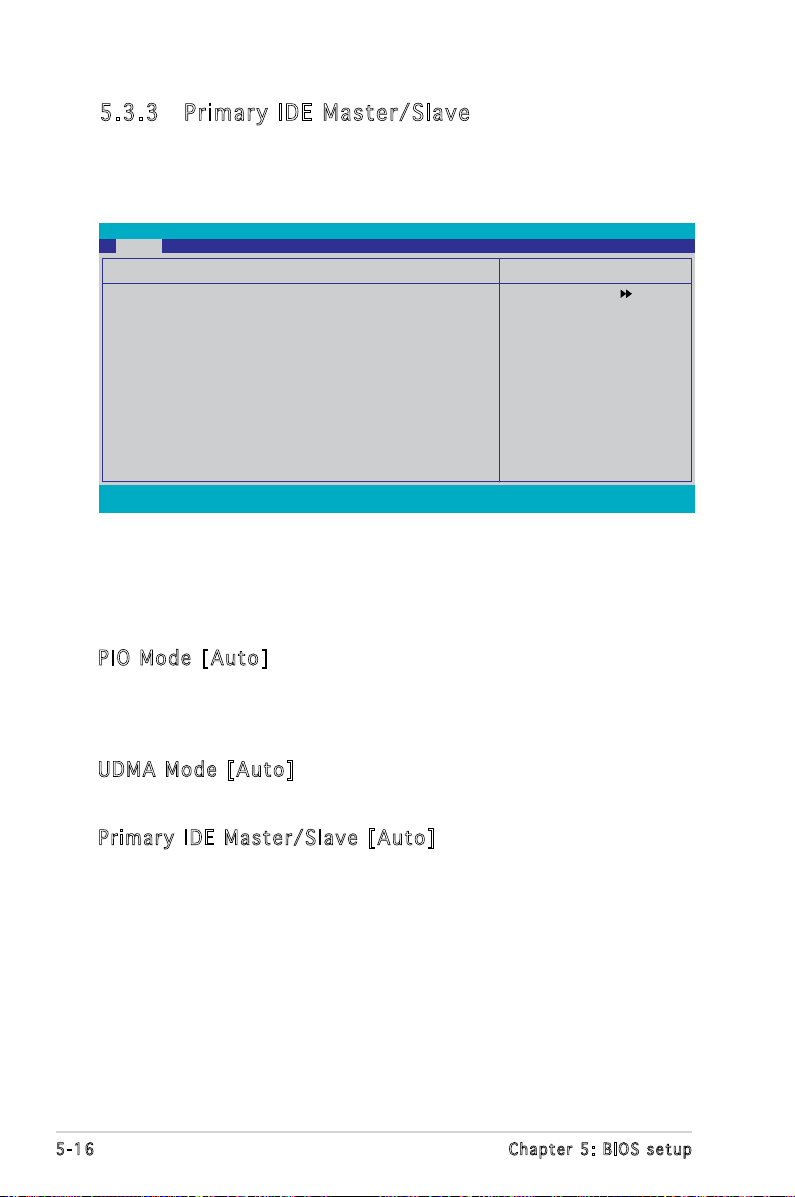
5.3 .3 Pri ma ry ID E Ma ste r/ Sl ave
While entering Setup, the BIOS automatically detects the presence of IDE
devices. There is a separate sub-menu for each IDE device. Select a device
item then press <Enter> to display the IDE device information.
Main
Primary IDE Master
Primary IDE Master [Auto]
Access Mode [Auto]
Capacity 0 MB
Cylinder 0
Head 0
Sector 0
PIO Mode [Auto]
UDMA Mode [Auto]
Transfer Mode None
F1:Help ↑↓ : Select Item -/+: Change Value F5: Setup Defaults
ESC: Exit →←: Select Menu Enter: Select SubMenu F10: Save and Exit
Phoenix-Award BIOS CMOS Setup Utility
Select Menu
Item Specic Help
Press [Enter] to select.
The BIOS automatically detects the values opposite the dimmed items
(Capacity, Cylinder, Head, Sector and Transfer Mode). These values are not
user-congurable. These items show N/A if no IDE device is installed in the
system.
PIO Mo d e [ A ut o ]
Sets the PIO mode for the IDE device.
Conguration options: [Auto] [Mode 0] [Mode 1] [Mode 2] [Mode 3]
[Mode 4]
UDM A M o de [ Au t o]
Disables or sets the UDMA mode. Conguration options: [Disabled] [Auto]
Pri m ar y ID E M a ste r /S l ave [A u to]
Select [Auto] to automatically detect an IDE hard disk drive. If automatic
detection is successful, the BIOS automatically lls in the correct values
for the remaining elds on this sub-menu. If the hard disk was already
formatted on a previous system, the setup BIOS may detect incorrect
parameters. Select [Manual] to manually enter the IDE hard disk drive
parameters. If no drive is installed select [None]. Conguration options:
[None] [Auto] [Manual]
5-16 Chapter 5: BIOS setup
Page 77

Acc e ss Mod e [ A uto ]
The default [Auto] allows automatic detection of an IDE hard disk drive.
Select [CHS] for this item if you set the IDE Primary Master/Slave to
[Manual]. Conguration options: [CHS] [LBA] [Large] [Auto]
Before attempting to congure a hard disk drive, make sure you have
the correct conguration information supplied by the drive manufacturer.
Incorrect settings may cause the system to fail to recognize the
installed hard disk.
Cap a ci t y
Displays the auto-detected hard disk capacity. This item is not
congurable.
Cyl i nd e r
Shows the number of the hard disk cylinders. This item is not congurable.
Hea d
Shows the number of the hard disk read/write heads. This item is not
congurable.
Sec t or
Shows the number of sectors per track. This item is not congurable.
Tra n sf e r M o de
Shows the Transfer mode. This item is not congurable.
After entering the IDE hard disk drive information into BIOS, use a disk
utility, such as FDISK, to partition and format new IDE hard disk drives.
This is necessary so that you can write or read data from the hard disk.
Make sure to set the partition of the Primary IDE hard disk drives to
active.
5-17ASUS Pundit P3-PE5
Page 78

5.3 .4 First / Second SATA Master
While entering Setup, the BIOS automatically detects the presence of Serial
ATA devices. There is a separate sub-menu for each SATA device. Select a
device item then press <Enter> to display the SATA device information.
Main
Extended IDE Drive [Auto]
Access Mode [Auto]
Capacity 0 MB
Cylinder 0
Head 0
Landing Zone 0
Sector 0
F1:Help ↑↓ : Select Item -/+: Change Value F5: Setup Defaults
ESC: Exit →←: Select Menu Enter: Select SubMenu F10: Save and Exit
Phoenix-Award BIOS CMOS Setup Utility
First SATA Master
Select Menu
Item Specic Help
Selects the type of xed
disk connected to the
system.
The BIOS automatically detects the values opposite the dimmed items
(Capacity, Cylinder, Head, Landing Zone and Sector). These values are not
user-congurable. These items show 0 if no SATA device is installed in the
system.
Ext e nd e d I D E D riv e [ A uto ]
Selects the type of xed disk connected to the system.
Conguration options: [None] [Auto]
Acc e ss Mod e [ A uto ]
Sets the sector addressing mode. Conguration options: [Large] [Auto]
Before attempting to congure a hard disk drive, make sure you have
the correct conguration information supplied by the drive manufacturer.
Incorrect settings may cause the system to fail to recognize the
installed hard disk.
Cap a ci t y
Displays the auto-detected hard disk capacity. This item is not
congurable.
Cyl i nd e r
Shows the number of the hard disk cylinders. This item is not congurable.
5-18 Chapter 5: BIOS setup
Page 79

Hea d
Shows the number of the hard disk read/write heads. This item is not
congurable.
Lan d in g Zo n e
Shows the number of landing zone per track. This item is not congurable.
Sec t or
Shows the number of sectors per track. This item is not congurable.
After entering the IDE hard disk drive information into BIOS, use a disk
utility, such as FDISK, to partition and format new IDE hard disk drives.
This is necessary so that you can write or read data from the hard disk.
Make sure to set the partition of the Primary IDE hard disk drives to
active.
5.3 .5 HDD S MA RT Mo ni tor in g [Di sa bl ed]
Allows you to enable or disable the HDD Self-Monitoring Analysis and
Reporting Technology (SMART) feature. Conguration options: [Disabled]
[Enabled]
5.3 .6 Ins ta ll ed Me mo ry [x xx MB ]
Shows the size of installed memory.
5.3 .7 Usa bl e Mem or y [XX X MB ]
Shows the size of usable memory.
5.4 Advanced menu
The Advanced menu items allow you to change the settings for the CPU
and other system devices.
Take caution when changing the settings of the Advanced menu items.
Incorrect eld values can cause the system to malfunction.
Main Advanced Power Boot Tools Exit
CPU Conguration
Chipset
PCIPnP
Onboard Device Conguration
USB Conguration
Phoenix-Award BIOS CMOS Setup Utility
Item Specic Help
Adjust system frequency/
voltage.
Select Menu
5-19ASUS Pundit P3-PE5
Page 80

5.4 .1 CPU C on fig ur at ion
Advanced
CPU Type Intel Genuine Processor
CPU Speed 3.80GHz
Cache RAM 2048K
Current FSB Frequency 200MHz
Delay Prior to Thermal [4 Min]
Thermal Management [TM 1]
TM2 Bus Ratio 14 X
TM2 Bus VID 0.8375V
Limit CPUID MaxVal [Disabled]
Enhanced C1 (C1E) [Enabled]
Excute Disable Bit [Enabled]
Enhanced Intel SpeedStep(tm) Tech.[Disabled]
CPU L1 & L2 Cache [Enabled]
Hyper-Threading TEchnology [Enabled]
The r ma l Ma n ag e men t [ TM 1 ]
Conguration options: [TM 1] [TM 2]. Thermal Monitor 1: On die throtting;
Thermal Monitor 2: Ratio & VID transition
Lim i t C PUI D M a xVa l [ D isa b le d ]
Conguration options: [Disabled] [Enabled].
Enh a nc e d C 1 ( C 1E) [En abl e d]
The process will lower the core to bus ratio and VID when physcial
pprocess enter an enhance C1 state. Conguration options: [Disabled]
[Enabled].
Exe c ut e Di s ab l e B i t [ Ena b le d ]
When disabled, forces the XD feature ag to always return 0. Conguration
options: [Disabled] [Enabled].
Phoenix-Award BIOS CMOS Setup Utility
CPU Conguration
Select Menu
Item Specic Help
DRAM timing and control.
Enh a nc e d I n te l Sp e ed S tep ( tm ) Te c h. [Di s ab l ed]
Enable this function for adjusting CPU speed according to CPU workload.
Conguration options: [Disabled] [Enabled].
CPU L1& L2 C ach e [ E nab led ]
Conguration options: [Disabled] [Enabled].
Hyp e r- T rea d in g Te c hn o log y [ E nab l ed ]
Set to [Enable] when using Windows XP and Linux 2.4.X, set to [Disabled]
when using other OS.
5-20 Chapter 5: BIOS setup
Page 81

5.4 .2 Chi ps et
Advanced
DRAM Clock/Drive Control
Frequency/Voltage control
Top Performance [Disabled]
Primary Display Adapter [PCI-E]
VGA Share Memory Size [64M]
F1:Help ↑↓ : Select Item -/+: Change Value F5: Setup Defaults
ESC: Exit →←: Select Menu Enter: Select Sub-menu F10: Save and Exit
DRA M C l ock / Dr i ve C on t rol
Advanced
Current DRAM Frequency 266MHz
DRAM Clock [By SPD]
DRAM Timing [Auto By SPD]
SDRAM CAS Latency [DDR/DDR2] 2.5/4
Bank Interleave Disabled
Precharge to Acive(Trp) 4T
Active to Precharge(Tras) 07T
Active to CMD(Trcd) 4T
REF to ACT/REF 20T/21T
ACT(0) to ACT(1) 3T
Phoenix-Award BIOS CMOS Setup Utility
Chipset
Phoenix-Award BIOS CMOS Setup Utility
DRAM Clock/Drive Control
Select Menu
Item Specic Help
Select Menu
Item Specic Help
F1:Help ↑↓ : Select Item -/+: Change Value F5: Setup Defaults
ESC: Exit →←: Select Menu Enter: Select Sub-menu F10: Save and Exit
DRAM Clock [By SPD]
Sets the DRAM clock. Conguration options: [By SPD] [200 MHz] [266
MHz].
DRAM Timing [Auto By SPD]
Sets the DRAM Timing. Conguration options: [Manual] [Auto by SPD]
[Turbo] [Ultra].
5-21ASUS Pundit P3-PE5
Page 82

Fre q ue n cy/ v ol t age co n tro l
Advanced
CPU Clock Ratio [19 X]
Async CPU/PCIE Clock [Sync Mode]
CPU Clock [200MHz]
Spread Spectrum [Disabled]
F1:Help ↑↓ : Select Item -/+: Change Value F5: Setup Defaults
ESC: Exit →←: Select Menu Enter: Select Sub-menu F10: Save and Exit
CPU Clock Ratio [19 X]
Sets the CPU clock ratio by keying in a DEC number. Min = 14, Max = 19.
Async CPU/PCIE Clock [Sync Mode]
Sets the Async CPU/PCIE clock. Conguration options: [Sync Mode] [Async
Mode].
CPU Clock [200MHz]
Sets the CPU clock by keying in a DEC number. Min = 200, Max = 232.
Spread Spectrum [Disabled]
Sets the spread spectrum. Conguration options: [Disabled] [+/- 0.1%]
[+/- 0.2%] [+/- 0.3%]...[+/- 1.0%].
Phoenix-Award BIOS CMOS Setup Utility
Frequency/Voltage control
Select Menu
Item Specic Help
Top Pe r for m an c e [ D is a ble d ]
Conguration options: [Disabled] [Enabled]
Pri m ar y Di s pl a y A d ap t er [ PC I -E]
Select which graphics controller to use as the primary boot device.
Conguration options: [PCI] [PCI-E]
VGA Sh a re M em o ry S iz e [6 4 M]
Sets the VGA Share Memory Size. Conguration options: [Disabled] [16M]
[32M] [64M]
5-22 Chapter 5: BIOS setup
Page 83

5.4 .3 PCI Pn P
Advanced
Phoenix-Award BIOS CMOS Setup Utility
PCIPnP
Plug & Play O/S [No]
Resources Controlled By [Auto]
x IRQ Resources
Assign IRQ For VGA [Enabled]
** PCI Express relative items **
Maximum Payload Size [4096]
Select Menu
Item Specic Help
Plu g & Pla y O / S [ N o]
When set to [No], the BIOS congures all the devices in the system.
When set to [Yes] and if you install a Plug and Play operating system, the
operating system congures the Plug and Play devices not required for
boot. Conguration options: [No] [Yes]
Res o ur c es C on t rol l ed By [ Au t o]
When set to [Auto], the BIOS automatically congures all the boot and
Plug and Play compatible devices. Set to [Manual] if you want to assign the
IRQ DMA and memory base address elds. Conguration options: [Auto]
[Manual]
The item IRQ Resources becomes user-congurable when you set
Resources Controlled By to [Manual].
IRQ Re s our c es
Advanced
IRQ-5 assigned to [PCI Device]
IRQ-7 assigned to [PCI Device]
IRQ-9 assigned to [PCI Device]
IRQ-10 assigned to [PCI Device]
IRQ-11 assigned to [PCI Device]
IRQ-14 assigned to [PCI Device]
IRQ-15 assigned to [PCI Device]
Phoenix-Award BIOS CMOS Setup Utility
IRQ Resources
Select Menu
Item Specic Help
Legacy ISA for devices
compliant with the original
PC AT bus specication,
PCI/ISA PnP for devices
compliant with the Plug
and Play standard whether
designed for PCI or ISA
bus architecture.
IRQ-xx assigned to
When set to [PCI Device], the specic IRQ is free for use of PCI/PnP
devices. When set to [Reserved], the IRQ is reserved for legacy ISA
devices. Conguration options: [PCI Device] [Reserved]
Ass i gn IRQ fo r VG A [ E nab l ed ]
Conguration options: [Enabled] [Disabled]
Max i mu m Pa y lo a d S i ze [40 9 6]
Conguration options: [128] [256] [512] [1024] [2048] [4096]
5-23ASUS Pundit P3-PE5
Page 84

5.4 .4 Onbo ar d Dev ic e Con fi gu rat io n
Advanced
Onboard Device Conguration
JMicron RAID controller [IDE]
SATA Controller [Enabled]
SATA Controller Mode [IDE]
Ex-SATA/PCI-E*1 Option [Ex-SATA]
HDA Controller [Auto]
Onboard LAN [Enabled]
Onboard LAN Boot ROM [Disabled]
Serial Port1 Address [3F8/IRQ4]
Parallel Port Address [378/IRQ7]
Parallel Port Mode [Bi-Directiional]
ECP Mode Use DMA [3]
Midi Port Address [330]
Midi Port IRQ [10]
F1:Help ↑↓ : Select Item -/+: Change Value F5: Setup Defaults
ESC: Exit →←: Select Menu Enter: Select Sub-menu F10: Save and Exit
JMi c ro n RA I D c ont r ol l er [ ID E ]
Allows you to disable JMicron RAID controller or sets to IDE/RAID mode.
Conguration options: [Disabled] [IDE] [RAID]
SAT A C o ntr o ll e r [ E na b led ]
Enable/Disable Onchip SATA. Conguration options: [Disabled] [Enabled]
SAT A C o ntr o ll e r M o de [ID E ]
Select SATA mode. Conguration options: [IDE] [RAID]
Ex- S AT A /PC I -E * 1 O p ti o n [ E x- S ATA ]
Allows you to switch Ex-SATA and PCI-E*1 controller.
Conguration options: [Ex-SATA] [PCI-E*1]
Phoenix-Award BIOS CMOS Setup Utility
Item Specic Help
Press [Enter] to set
Select Menu
HDA Co n tro l le r [A u to ]
Enable/Disable High Denition Audio controller. Conguration options:
[Auto] [Disabled]
Onb o ar d LA N [ E nab l ed ]
Enable/Disable onboard LAN. Conguration options: [Enabled] [Disabled]
Onb o ar d LA N B o ot R OM [Di s ab l ed]
Enable/Disable the bootrom of the onboard LAN. Conguration options:
[Enabled] [Disabled]
Ser i al Por t 1 A ddr e ss [3F 8 /IR Q4]
Enable/Disable the bootrom of the onboard LAN. Conguration options:
[Enabled] [Disabled]
5-24 Chapter 5: BIOS setup
Page 85

Par a ll e l P o rt Add r es s [3 7 8/I RQ7 ]
Select parallel port address. Conguration options: [Disabled] [378/IRQ7]
[278/IRQ5] [3BC/IRQ7]
Par a ll e l P o rt Mod e [ B i-D i re c tio n al ]
Select parallel port mode. Conguration options: [Normal] [EPP] [ECP] [Bi-
Directional]
ECP Mo d e U s e D MA [ 3]
Select ECP Mode use DMA. Conguration options: [1] [3]
Mid i P o rt A dd r ess [3 3 0]
Select Midi port address. Conguration options: [Disabled] [330] [300]
Mid i P o rt I RQ [10 ]
Select Midi port IRQ. Conguration options: [5] [10]
5.4 .5 USB Co nf igu ra ti on
The items in this menu allows you to change the USB-related features.
Select an item then press <Enter> to display the conguration options.
Advanced
USB Controller [Enabled]
USB2.0 Controller [Enabled]
USB Legacy support [Enabled]
Phoenix-Award BIOS CMOS Setup Utility
USB Conguration
Select Menu
Item Specic Help
Enable or Disable the USB
Controller.
USB Co n tro l le r [E n ab l ed]
Enable or disable USB 1.1 and 2.0 controller. Conguration options:
[Disabled] [Enabled]
USB 2.0 Co n tro lle r [E nab l ed]
Enables or disables the USB 2.0 controller. Conguration options: [Disabled]
[Enabled]
USB Le g acy su p por t [ A uto ]
Enable/Disable USB legacy device (USB keyboard and USB mouse) support.
Conguration options: [Auto] [Enabled] [Disabled]
5-25ASUS Pundit P3-PE5
Page 86

5.5 Power menu
The Power menu items allow you to change the settings for the Advanced
Conguration and Power Interface (ACPI) and the Advanced Power
Management (APM). Select an item then press <Enter> to display the
conguration options.
Main Advanced Power Boot Tools Exit
ACPI Suspend Type [S1&S3]
ACPI APIC support [Enabled]
APM Conguration
Hardware Monitor
F1:Help ↑↓ : Select Item -/+: Change Value F5: Setup Defaults
ESC: Exit →←: Select Menu Enter: Select SubMenu F10: Save and Exit
5.5 .1 ACP I Su spe nd T ype [ S1 &S3 ]
Allows you to select the Advanced Conguration and Power Interface
(ACPI) state to be used for system suspend. Conguration options: [S1
(POS)] [S3(STR)] [S1&S3]
5.5 .2 ACP I AP IC Su pp ort [ En abl ed ]
Allows you to enable or disable the Advanced Conguration and Power
Interface (ACPI) support in the Application-Specic Integrated Circuit
(ASIC). When set to Enabled, the ACPI APIC table pointer is included in the
RSDT pointer list. Conguration options: [Disabled] [Enabled]
Phoenix-Award BIOS CMOS Setup Utility
Item Specic Help
Press [Enter] to select
whether or not to restart
the system after AC power
loss.
Select Menu
5-26 Chapter 5: BIOS setup
Page 87

5.5 .3 APM C on fig ur at ion
Power
Power Up By PS/2 Mouse [Disabled]
Power Up By PS/2 Keyboard [Disabled]
Power on By PCI Devices [Disabled]
Power on By External Modem [Disabled]
Power on By On-board LAN [Disabled]
Power On By RTC Alarm [Disabled]
x Date (of Month) Alarm 0
x Time (hh:mm:ss) Alarm 0 : 0 : 0
Restore on AC Power Loss [Power Off]
PWR Button < 4 secs [Instant-Off]
F1:Help ↑↓ : Select Item -/+: Change Value F5: Setup Defaults
ESC: Exit →←: Select Menu Enter: Select SubMenu F10: Save and Exit
Phoenix-Award BIOS CMOS Setup Utility
APM Conguration
Select Menu
Item Specic Help
Pow e r U p B y P S /2 M ous e [ D isa ble d ]
Disable or enable Power up by PS/2 Mouse function.
Conguration options: [Disabled] [Enabled]
Pow e r U p B y P S /2 K eyb oar d [D isa b led ]
Enable or disable Power up by PS/2 Keyboard function. Conguration
options: [Disabled] [Enabled]
Pow e r O n B y P C I D e vi c es [ Di s abl e d]
Enable or disable Power on by PCI Devices function. Conguration options:
[Disabled] [Enabled]
Pow e r o n B y E x ter n al Mod e m [ Dis a bl e d]
Enable or disable Power on By External Modem function. Conguration
options: [Disabled] [Enabled]
Pow e r o n B y O n -bo a rd LAN [D i sab l ed ]
Enable or disable Wake up on LAN function.Conguration options: [Insant-
Off] [Suspend]
Pow e r o n B y R T C A l ar m [D i sa b led ]
Enable or disable Power on by RTC Alarm function.When this function is
enabled, you can set the date and time of the resume by alarm function.
Conguration options: [Insant-Off] [Suspend]
5-27ASUS Pundit P3-PE5
Page 88

Res t or e on AC Pow e r L oss [P o wer Of f ]
Allows you to select to/not to restart the system after AC power loss.
Conguration options: [Power Off] [Power On] [Last State]
PWR Bu t ton < 4 se c s [ Ins t an t -Of f ]
When sets to [Instant-Off], the system will go to Soft-off instantly when
power-button pressed for less than 4 seconds. When sets to [Suspend],
the system will go to Suspend when power button is pressed.
Conguration options: [Suspend] [Instant-Off]
5-28 Chapter 5: BIOS setup
Page 89

5.5 .4 Har dw ar e M on it or
The items in this sub-menu displays the hardware monitor values
automatically detected by the BIOS. It also allows you to change CPU Q-Fan
feature-related parameters. Select an item then press <Enter> to display
the conguration options.
Power
Q-Fan Controller [Enabled]
Vcore Voltage [1.29V]
3.3V Voltage [3.33V]
5V Voltage [4.96V]
x 12V Voltage [11.96V]
CPU Temperature 54C
M/B Temperature 40C
CPU Fan Speed 2136 RPM
CPU Fan Speed warning [800 RPM]
Start Up Temperature (C) [50]
Full Speed Temperature (C) [70]
Start Up PWM [60]
Slope PWM [4 PWM/C]
F1:Help ↑↓ : Select Item -/+: Change Value F5: Setup Defaults
ESC: Exit →←: Select Menu Enter: Select SubMenu F10: Save and Exit
Q-F a n C ont r ol l er [ En a ble d ]
Disable or Enable the Q-Fan controller. Conguration options: [Disabled]
[Enabled]
Vco r e V olt a ge [En a bl e d]
Sets the Vcore Voltage. Conguration options: [1.29V] [Ignored]
Phoenix-Award BIOS CMOS Setup Utility
Hardware Monitor
Select Menu
Item Specic Help
Press [Enter] to enable or
disable.
3.3 V Vo lta g e, 5V V olt age , 12 V V o lta ge
The onboard hardware monitor automatically detects the voltage output
through the onboard voltage regulators.
CPU Te m per a tu r e, M /B Tem p er a tur e
The onboard hardware monitor automatically detects and displays the
motherboard and CPU temperatures. These items are not user-congurable.
CPU Fa n Sp e ed
The o n b oard h a rdwa r e moni t o r aut o m a tica l l y det e c t s an d
disp l a y s th e C PU f a n spee d s in r o t a tion s p er m i n u te ( R P M ).
Thes e i tems a r e no t u ser- c o n figu r a b le.
CPU Fa n Sp e ed war n in g [ 8 00 R PM ]
Allows you to disable or set the CPU fan warning speed.
Conguration options: [Disabled] [800 RPM] [1200 RPM] [1600 RPM]
5-29ASUS Pundit P3-PE5
Page 90

Sta r t U p T e mp e rat u re (C) [50 ]
Fan will srart up when temperature over this value. Sets the value by keying
in a DEC number. Min = 0, Max = 100.
Ful l S p eed Te m per a tu r e ( C ) [ 70]
Fan will become full speed when temperature over this value. Sets the value
by keying in a DEC number. Min = 0, Max = 100.
Sta r t U p P W M [ 60]
Set P W M val u e when f a n st a r t up. S e ts t h e valu e b y ke y i n g in a
DEC n u m ber. M i n = 0 , Max = 1 2 7.
Slo p e P WM [ 4 P WM/ C ]
Set PWM increase value when temperature up one degree. Conguration
options: [0 PWM/C] [1 PWM/C] [2 PWM/C] [4 PWM/C] [8 PWM/C]...[64
PWM/C]
5-30 Chapter 5: BIOS setup
Page 91

5.6 Boot menu
The Boot menu items allow you to change the system boot options. Select
an item then press <Enter> to display the sub-menu.
Main Advanced Power Boot Tools Exit
Boot Device Priority
Removable Drives
Hard Disk Drives
Boot Settings Conguration
Security
F1:Help ↑↓ : Select Item -/+: Change Value F5: Setup Defaults
ESC: Exit →←: Select Menu Enter: Select Sub-menu F10: Save and Exit
5.6 .1 Boo t De vic e Pr ior it y
Boot
1st Boot Device [Hard Disk]
2nd Boot Device [CDROM]
3rd Boot Device [CDROM]
4th Boot Device [Disabled]
1st ~ 4 th B oot De v ice
These items specify the boot device priority sequence from the available
devices. The number of device items that appears on the screen depends
on the number of devices installed in the system. Conguration options:
[Removable] [Hard Disk] [CDROM] [Legacy LAN] [Disabled]
Rem o va b le D ri v es
This item lists the detected removable drives and allows you to select
removable boot device priority. Select a device from the list and use <+>
and <-> to move it up /down in the list.
Phoenix-Award BIOS CMOS Setup Utility
Phoenix-Award BIOS CMOS Setup Utility
Boot Device Priority
Select Menu
Item Specic Help
Select Boot Device
Priority
Select Menu
Item Specic Help
Select Your Boot
Device Priority
5.6 .2 Har d Di sk Dr iv es
Allows you to assign hard disk drives attached to the system.
Boot
1. Bootable Add-in Cards
Phoenix-Award BIOS CMOS Setup Utility
Hard Disk Drives
Select Menu
Item Specic Help
5-31ASUS Pundit P3-PE5
Page 92

5.6 .3 Boo t Se tti ng s Con fi gu rat io n
Boot Settings Conguration
Case Open Warning [Enabled]
Quick Boot [Enabled]
Boot Up Floppy Seek [Disabled]
Bootup Mun-Lock [On]
Typematic Rate Setting [Disabled]
x Typematic Rate (Chars/Sec) 6
x Typematic Delay (Msec) 250
OS Select For DRAM > 64MB [Non-OS2]
Full Screen LOGO [Enabled]
Halt On [All, But Keyboard]
F1:Help ↑↓ : Select Item -/+: Change Value F5: Setup Defaults
ESC: Exit →←: Select Menu Enter: Select Sub-menu F10: Save and Exit
Phoenix-Award BIOS CMOS Setup Utility
Boot
Item Specic Help
Press [Enter] to
enable or disable.
Select Menu
Cas e O p en W ar n ing [E n abl e d]
Allows you to enable or disable the Case Open Warning feature.
Conguration options: [Disabled] [Enabled]
Qui c k B oot [E n abl e d]
Allows the system to skip certain tests while booting. This will decrease
the time needed to boot the system. Conguration options: [Disabled]
[Enabled]
Boo t U p Fl o pp y Se e k [ Dis a bl e d]
Allows the system to test oppy drives to determine whether they have 40
or 80 tracks. Conguration options: [Disabled] [Enabled]
Boo t U p Nu m -L o ck [ On ]
Selects power on state for NumLock. Conguration options: [Off] [On]
Typ e ma t ic R at e Se t ti n g [ D is a ble d ]
Keystrokes repeat at a rate determined by the keyboard controller when enabled, the typematic rate and typematic delay can be selected.
Conguration options: [Disabled] [Enabled]
5-32 Chapter 5: BIOS setup
Page 93

OS S el e ct f or DRA M > 64M B [ N on- O S2]
Set this item to OS2 only when you are running on an OS/2 operating
system with an installed RAM of greater than 64 KB. Conguration options:
[Non-OS2] [OS2]
Ful l S c ree n L O GO [ En a ble d ]
Allows you to enable or disable the full screen logo display feature.
Conguration options: [Disabled] [Enabled]
Hal t O n [A l l, But Ke y boa r d]
Allows you to error report type.
Conguration options: [All Errors] [No Errors] [All, But Keyboard] [All, But
Diskette] [All, But Disk/Key]
5.6 .4 Sec ur it y
Boot
Supervisor Password Clear
User Password Clear
Password Check [Setup]
Sup e rv i sor Pa s swo r d
Use r P a ssw o rd
These elds allow you to set passwords:
To set a password:
Phoenix-Award BIOS CMOS Setup Utility
Security
Item Specic Help
Select Menu
1. Select an item then press <Enter>.
2. Type in a password using a combination of a maximum of eight (8)
alpha-numeric characters, then press <Enter>.
3. When prompted, conrm the password by typing the exact characters
again, then press <Enter>. The password eld setting is changed to
Set.
To clear the password:
1. Select the password eld and press <Enter> twice. The following
message appears:
PASSWORD DISABLED !!!
Press any key to continue...
5-33ASUS Pundit P3-PE5
Page 94

2. Press any key to continue. The password eld setting is changed to
Clear.
A note about passwords
The Supervisor password is required to enter the BIOS Setup program
preventing unauthorized access. The User password is required to
boot the system preventing unauthorized use.
Forgot your password?
If you forget your password, you can clear it by erasing the CMOS
Real Time Clock (RTC) RAM. The RAM data containing the password
information is powered by the onboard button cell battery. If you
need to erase the CMOS RAM, refer to section “2.6 Jumper” for
instructions.
Pas s wo r d C h ec k
This eld requires you to enter the password before entering the BIOS
setup or the system. Select [Setup] to require the password before
entering the BIOS Setup. Select [System] to require the password before
entering the system. Conguration options: [Setup] [System]
5.7 Exit menu
The Exit menu items allow you to load the optimal or failsafe default values
for the BIOS items, and save or discard your changes to the BIOS items.
Main Advanced Power Boot Tools Exit
Exit & Save Changes
Exit & Discard Changes
Load Setup Default
Discard Changes
Phoenix-Award BIOS CMOS Setup Utility
Item Specic Help
This option save data
to CMOS and exiting
the setup menu.
Select Menu
F1:Help ↑↓ : Select Item -/+: Change Value F5: Setup Defaults
ESC: Exit →←: Select Menu Enter: Select Sub-menu F10: Save and Exit
5-34 Chapter 5: BIOS setup
Page 95

Pressing <Esc> does not immediately exit this menu. Select one of the
options from this menu or <F10> from the legend bar to exit.
Exi t & Sav e C h ang e s
Once you are nished making your selections, choose this option from the
Exit menu to ensure the values you selected are saved to the CMOS RAM.
An onboard backup battery sustains the CMOS RAM so it stays on even
when the PC is turned off. When you select this option, a conrmation
window appears. Select YES to save changes and exit.
If you attempt to exit the Setup program without saving your changes,
the program prompts you with a message asking if you want to save
your changes before exiting. Press <Enter> to save the changes while
exiting.
Exi t & Dis c ar d Ch a ng e s
Select this option only if you do not want to save the changes that you
made to the Setup program. If you made changes to elds other than
System Date, System Time, and Password, the BIOS asks for a conrmation
before exiting.
ASU S E Z Fl a sh 2
Press Enter to run ASUS EZ Flash 2 utility.
Loa d S e tup De f aul t s
This option allows you to load the default values for each of the
parameters on the Setup menus. When you select this option or if you
press <F5>, a conrmation window appears. Select YES to load default
values. Select Exit & Save Changes or make other changes before saving
the values to the non-volatile RAM.
Dis c ar d Ch a ng e s
This option allows you to discard the selections you made and restore the
previously saved values. After selecting this option, a conrmation appears.
Select YES to discard any changes and load the previously saved values.
5-35ASUS Pundit P3-PE5
 Loading...