

Page 1
P3-P5G43
ASUS PC (Desktop Barebone)
User Manual
Download the latest manual from the ASUS website: www.asus.com
Page 2

E4226
First Edition
December 2008
Copyright © 2008 ASUSTeK Computer Inc. All Rights Reserved.
No part of this manual, including the products and software described in it, may be reproduced,
transmitted, transcribed, stored in a retrieval system, or translated into any language in any form or by any
means, except documentation kept by the purchaser for backup purposes, without the express written
permission of ASUSTeK Computer Inc. (“ASUS”).
Product warranty or service will not be extended if: (1) the product is repaired, modied or altered, unless
such repair, modication of alteration is authorized in writing by ASUS; or (2) the serial number of the
product is defaced or missing.
ASUS PROVIDES THIS MANUAL “AS IS” WITHOUT WARRANTY OF ANY KIND, EITHER EXPRESS
OR IMPLIED, INCLUDING BUT NOT LIMITED TO THE IMPLIED WARRANTIES OR CONDITIONS OF
MERCHANTABILITY OR FITNESS FOR A PARTICULAR PURPOSE. IN NO EVENT SHALL ASUS, ITS
DIRECTORS, OFFICERS, EMPLOYEES OR AGENTS BE LIABLE FOR ANY INDIRECT, SPECIAL,
INCIDENTAL, OR CONSEQUENTIAL DAMAGES (INCLUDING DAMAGES FOR LOSS OF PROFITS,
LOSS OF BUSINESS, LOSS OF USE OR DATA, INTERRUPTION OF BUSINESS AND THE LIKE),
EVEN IF ASUS HAS BEEN ADVISED OF THE POSSIBILITY OF SUCH DAMAGES ARISING FROM ANY
DEFECT OR ERROR IN THIS MANUAL OR PRODUCT.
SPECIFICATIONS AND INFORMATION CONTAINED IN THIS MANUAL ARE FURNISHED FOR
INFORMATIONAL USE ONLY, AND ARE SUBJECT TO CHANGE AT ANY TIME WITHOUT NOTICE,
AND SHOULD NOT BE CONSTRUED AS A COMMITMENT BY ASUS. ASUS ASSUMES NO
RESPONSIBILITY OR LIABILITY FOR ANY ERRORS OR INACCURACIES THAT MAY APPEAR IN THIS
MANUAL, INCLUDING THE PRODUCTS AND SOFTWARE DESCRIBED IN IT.
Products and corporate names appearing in this manual may or may not be registered trademarks or
copyrights of their respective companies, and are used only for identication or explanation and to the
owners’ benet, without intent to infringe.
ii
Page 3

Contents
Notices .......................................................................................................... v
Safety information ...................................................................................... vi
About this guide ........................................................................................ vii
System package contents .......................................................................... ix
Chapter 1: System introduction
1.1 Welcome! ...................................................................................... 1-2
1.2 Front panel ....................................................................................
1.3 Rear panel .....................................................................................
1.4 Internal components ....................................................................
Chapter 2: Getting started
2.1 Installing an operating system ................................................... 2-2
2.2 Support CD information ..............................................................
2.2.1 Running the support CD .................................................
2.2.2 Drivers menu ...................................................................
2.2.3 Utilities menu ..................................................................
2.2.4 Manual menu ..................................................................
2.2.5 ASUS contact information ...............................................
2.2.6 Other information ............................................................
Chapter 3: Motherboard info
3.1 Motherboard overview ................................................................. 3-2
3.2 Jumpers ........................................................................................
3.3 Connectors ...................................................................................
3.3.1 Rear panel connectors ....................................................
3.3.2 Internal connectors .........................................................
1-2
1-4
1-7
2-2
2-2
2-3
2-4
2-5
2-6
2-7
3-3
3-5
3-5
3-5
Chapter 4: BIOS setup
4.1 Managing and updating your BIOS ............................................ 4-2
4.1.1 Creating a bootable oppy disk .......................................
4.1.2 ASUS EZ Flash 2 utility ...................................................
4.1.3 AFUDOS utility ................................................................
4.1.4 ASUS CrashFree BIOS 3 utility ......................................
4.1.5 ASUS Update utility ........................................................
4.2 BIOS setup program ..................................................................
4.2.1 BIOS menu screen ........................................................
4-2
4-4
4-5
4-7
4-9
4-12
4-13
iii
Page 4

Contents
4.2.3 Navigation keys ............................................................. 4-13
4.2.2 Menu bar .......................................................................
4.2.4 Menu items ...................................................................
4.2.5 Sub-menu items ............................................................
4.2.6 Conguration elds .......................................................
4.2.7 Pop-up window .............................................................
4.2.8 Scroll bar .......................................................................
4.2.9 General help .................................................................
4.3 Main menu ..................................................................................
4.3.1 System Time ................................................................
4.3.2 System Date ................................................................
4.3.3 SATA 1~2 ......................................................................
4.3.4 Storage Conguration ...................................................
4.3.5 System Information .......................................................
4.4 Advanced menu .........................................................................
4.4.1 JumperFree Conguration ............................................
4.4.2 CPU Conguration ........................................................
4.4.3 Chipset ..........................................................................
2.4.4 Onboard Devices Conguration ....................................
4.4.5 USB Conguration ........................................................
4.4.6 PCI PnP ........................................................................
4.5 Power menu ................................................................................
4.5.1 Suspend Mode .............................................................
2.5.2 ACPI 2.0 Support .........................................................
2.5.3 ACPI APIC Support ......................................................
4.5.4 APM Conguration ........................................................
4.5.5 Hardware Monitor .........................................................
4.6 Boot menu ..................................................................................
4.6.1 Boot Device Priority ......................................................
4.6.2 Boot Settings Conguration ..........................................
4.6.3 Security .........................................................................
4.7 Tools menu .................................................................................
4.7.1 ASUS EZ Flash 2 ..........................................................
4.7.2 Express Gate ...............................................................
4.7.3 AI NET 2
4.8 Exit menu ....................................................................................
........................................................................ 4-39
4-13
4-14
4-14
4-14
4-14
4-14
4-14
4-15
4-15
4-15
4-16
4-17
4-18
4-19
4-19
4-22
4-24
4-27
4-28
4-29
4-30
4-30
4-30
4-30
4-31
4-32
4-33
4-33
4-34
4-35
4-37
4-37
4-38
4-40
iv
Page 5

Notices
Federal Communications Commission Statement
This device complies with Part 15 of the FCC Rules. Operation is subject to the
following two conditions:
•
This device may not cause harmful interference, and
•
This device must accept any interference received including interference that
may cause undesired operation.
This equipment has been tested and found to comply with the limits for a
Class B digital device, pursuant to Part 15 of the FCC Rules. These limits are
designed to provide reasonable protection against harmful interference in a
residential installation. This equipment generates, uses and can radiate radio
frequency energy and, if not installed and used in accordance with manufacturer’s
instructions, may cause harmful interference to radio communications. However,
there is no guarantee that interference will not occur in a particular installation. If
this equipment does cause harmful interference to radio or television reception,
which can be determined by turning the equipment off and on, the user is
encouraged to try to correct the interference by one or more of the following
measures:
•
Reorient or relocate the receiving antenna.
•
Increase the separation between the equipment and receiver.
•
Connect the equipment to an outlet on a circuit different from that to which the
receiver is connected.
•
Consult the dealer or an experienced radio/TV technician for help.
WARNING! The use of shielded cables for connection of the monitor to the
graphics card is required to assure compliance with FCC regulations. Changes
or modications to this unit not expressly approved by the party responsible for
compliance could void the user’s authority to operate this equipment.
Canadian Department of Communications Statement
This digital apparatus does not exceed the Class B limits for radio noise emissions
from digital apparatus set out in the Radio Interference Regulations of the
Canadian Department of Communications.
This class B digital apparatus complies with Canadian ICES-003.
Macrovision Corporation Product Notice
This product incorporates copyright protection technology that is protected by
U.S. patents and other intellectual property rights. Use of this copyright protection
technology must be authorized by Macrovision, and is intended for home and other
limited viewing uses only unless otherwise authorized by Macrovision. Reverse
engineering or disassembly is prohibited.
v
Page 6

Safety information
Electrical safety
•
To prevent electrical shock hazard, disconnect the power cable from the
electrical outlet before relocating the system.
•
When adding or removing devices to or from the system, ensure that the power
cables for the devices are unplugged before the signal cables are connected.
•
If the power supply is broken, do not try to x it by yourself. Contact a qualied
service technician or your retailer.
Operation safety
•
Before installing devices into the system, carefully read all the documentation
that came with the package.
•
Before using the product, make sure all cables are correctly connected and the
power cables are not damaged. If you detect any damage, contact your dealer
immediately.
•
To avoid short circuits, keep paper clips, screws, and staples away from
connectors, slots, sockets and circuitry.
•
Avoid dust, humidity, and temperature extremes. Do not place the product in
any area where it may become wet. Place the product on a stable surface.
• Do not block the air vents on the chassis. Always provide proper
ventilation for this product.
• We recommend that you use this product in environments with an
ambient temperature below 40oC.
If you encounter technical problems with the product, contact a qualied
•
service technician or your retailer.
Lithium-Ion Battery Warning
CAUTION: Danger of explosion if battery is incorrectly replaced. Replace
only with the same or equivalent type recommended by the manufacturer.
Dispose of used batteries according to the manufacturerís instructions.
VORSICHT: Explosionsgetahr bei unsachgemäßen Austausch der Batterie.
Ersatz nur durch denselben oder einem vom Hersteller empfohlenem
ähnljchen Typ. Entsorgung gebrauchter Batterien nach Angaben des
Herstellers.
LASER PRODUCT WARNING
CLASS 1 LASER PRODUCT
vi
Page 7

About this guide
Audience
This guide provides general information and installation instructions about the
ASUS P3-P5G43 barebone system. This guide is intended for experienced users
and integrators with hardware knowledge of personal computers.
How this guide is organized
This guide contains the following parts:
1. Chapter 1: System introduction
This chapter gives a general description of the barebone system. The chapter
lists the system features including introduction on the front and rear panels,
and internal components.
2. Chapter 2: Getting started
This chapter helps you power up the system and install drivers and utilities
from the support CD.
3. Chapter 3: Motherboard info
This chapter gives information about the motherboard that comes with the
system. This chapter includes the motherboard layout, jumper settings, and
connector locations.
4. Chapter 4: BIOS setup
This chapter tells how to change system settings through the BIOS Setup
menus and describes the BIOS parameters.
vii
Page 8

Conventions used in this guide
WARNING: Information to prevent injury to yourself when trying to
complete a task.
CAUTION: Information to prevent damage to the components when
trying to complete a task.
IMPORTANT: Instructions that you MUST follow to complete a task.
NOTE: Tips and additional information to aid in completing a task.
Where to nd more information
Refer to the following sources for additional information and for product and
software updates.
1. ASUS Websites
The ASUS websites worldwide provide updated information on ASUS
hardware and software products. Refer to the ASUS contact information.
2. Optional Documentation
Your product package may include optional documentation, such as warranty
yers, that may have been added by your dealer. These documents are not
part of the standard package.
viii
Page 9

System package contents
Check your P3-P5G43 system package for the following items.
If any of the items is damaged or missing, contact your retailer immediately.
Item description
1. ASUS P3-P5G43 barebone system with
• ASUS motherboard
• 220 W PFC power supply unit
• 6-in-1 storage card reader
2. Accessories
• Foot stand and screw (1 pair) for vertical placement
• Rubber stand (x 4) for horizontal placement
• Hard disk drive screw (x 8)
• Optical drive screw (x 2)
• Rubber washer (x 8)
3. Cables
• AC power cable
• Serial ATA signal cable (x 2)
• IDE cable (x 1)
4. Support CD
5. Quick Installation Guide
ix
Page 10

x
Page 11
Chapter 1
This chapter gives a general
description of the barebone system.
The chapter lists the system features
including introduction on the front and
rear panels, and internal components.
System introduction
Page 12
1.1 Welcome!
Thank you for choosing the ASUS P3-P5G43!
The ASUS P3-P5G43 is an all-in-one barebone system with powerful and exible
features.
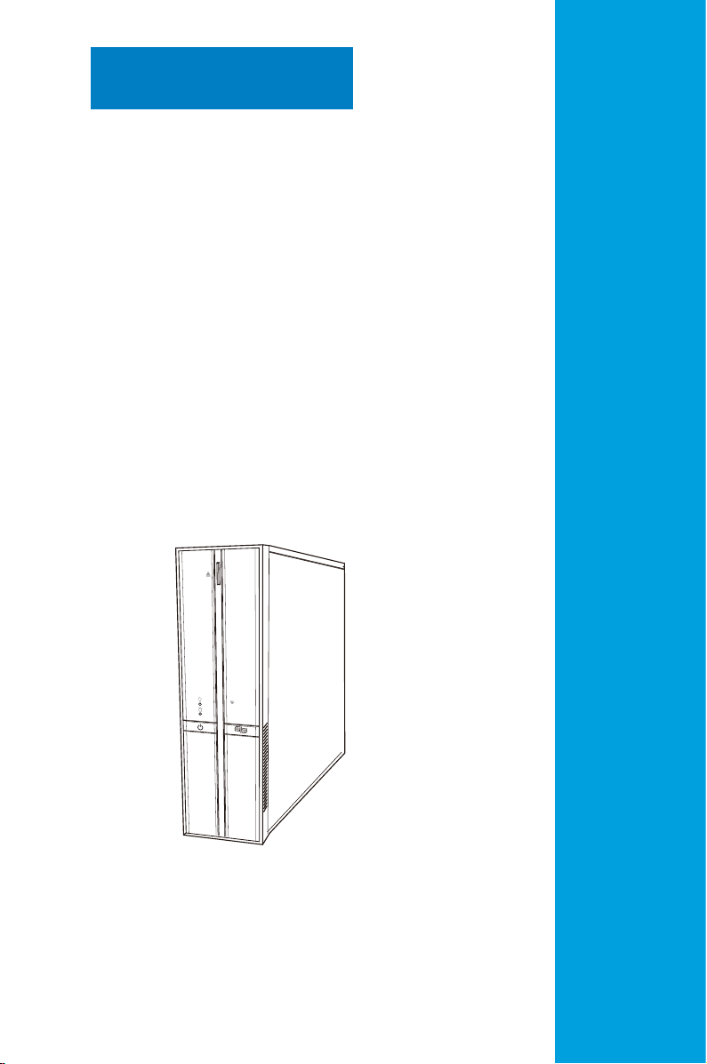
The system comes in a stylish book-size casing, and powered by the ASUS
motherboard that supports the Intel® CoreTM 2 Quad / CoreTM 2 Extreme /
TM
Core
2 Duo / Pentium® Extreme / Pentium® D / Pentium® 4 / Celeron® processors
in the 775-land package.
With audio capabilities, extensive connectivity, and Fast Ethernet LAN, P3-P5G43
is designed for the sophisticated. The system’s ergonomic design allows vertical or
horizontal placement so you can maximize your desktop space.
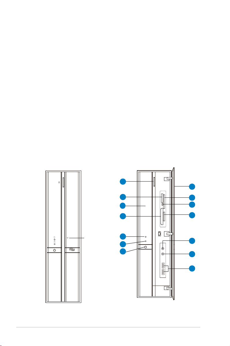
1.2 Front panel
The front panel includes the front panel cover, connectors, power button, and
LEDs.
Close Open
1
2
3
4
Press here to
open the front
panel cover
1-2 Chapter 1: System introduction
5
6
7
8
9
10
11
12
13
14
Page 13
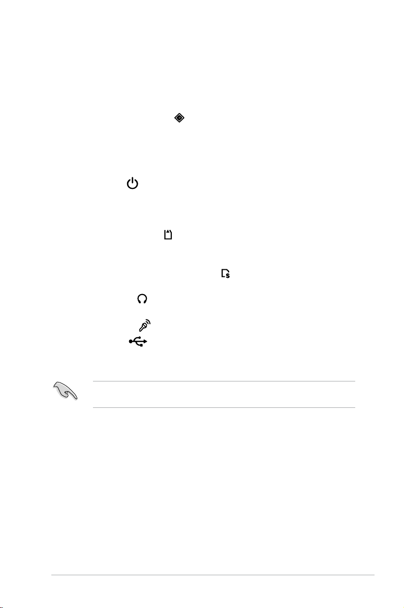
1. Optical drive eject button. Press this button to eject the optical drive tray.
®
2. Memory Stick
/Memory Stick Pro™ card slot*. This slot is for a Memory
Stick®/Memory Stick Pro™ storage card.
3. Optical drive/bay cover.
Covers the optical drive or optical drive bay.
4. CompactFlash® card slot* . This slot is for a CompactFlash® storage
card.
5. Power LED.
6. HDD LED.
This LED lights up to indicate that the system is ON.
This LED lights up when data is being read from or written to the
hard disk drive.
7. Power button . Press this button to turn the system on or off.
8. Front panel cover.
Covers the 6-in-1 card reader and front panel I/O ports.
Press the indicated area to open the front panel cover. Refer to the illustration
in the previous page.
9. SmartMedia
10. Card reader LED.
®
card slot* . This slot is for a SmartMedia® storage card.
This LED lights up when data is being read from or written
to a storage card inserted in any of the card reader slots.
11. Secure Digital™/MultimediaCard slot*
. This slot is for a Secure
Digital™/MultimediaCard storage card.
12. Headphone port
. This port connects a headphone with a stereo
mini-plug.
13. Microphone port
14. USB 2.0 ports
. This Mic (pink) port connects a microphone.
. These Universal Serial Bus 2.0 (USB 2.0) ports are
available for connecting USB 2.0 devices such as a mouse, printer, scanner,
camera, PDA, and others.
* Use and format a storage card according to the documentation that comes
with it.
1-3ASUS P3-P5G43
Page 14
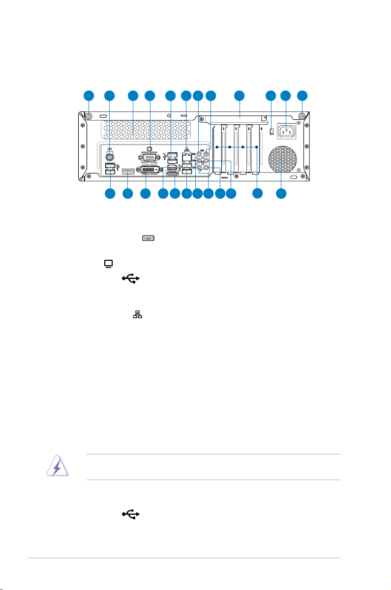
1.3 Rear panel
1394
ESATA
DVI
HDMI
The system rear panel includes the power connector and several I/O ports that
allow convenient connection of devices.
1
12 13 14 16 17
18 19 20 2115
10 11765432 18 9
22
23
1. Cover screw. Secures the system cover.
2. PS/2 keyboard port
3. Air vent.
4. VGA port
Provides ventilation for the system.
. Connects a VGA monitor.
5. USB 2.0 ports
. This 6-pin connector is for a PS/2 keyboard.
. These Universal Serial Bus 2.0 (USB 2.0) ports are
available for connecting USB 2.0 devices such as a mouse, printer, scanner,
camera, PDA, and others.
6. LAN (RJ-45) port
. This port allows Fast Ethernet connection to a Local
Area Network (LAN) through a network hub.
7. Center / Subwoofer port (orange).
This port connects the center /
subwoofer speakers.
8. Line In port (light blue).
This port connects a tape, CD, DVD player, or other
audio sources.
9. Metal bracket lock.
10. Voltage selector.
Secures the expansion slot/card metal brackets.
Allows you to adjust the system input voltage according to
the voltage supply in your area. If the voltage supply in your area is 100-127
V, set the switch to 115 V. If the voltage supply in your area is 200-240 V, set
the switch to 230 V.
Setting the switch to 115 V in a 230 V environment will seriously damage the
system!
11. Power connector. Connects the power cable and plug.
12. USB 2.0 ports
. These Universal Serial Bus 2.0 (USB 2.0) ports are
available for connecting USB 2.0 devices such as a mouse, printer, scanner,
camera, PDA, and others.
1-4 Chapter 1: System introduction
Page 15
13. HDMI port. This port is for a High-Denition Multimedia Interface (HDMI)
connector, and is HDCP compliant allowing playback of HD DVD, Blu-Ray
and other protected content
14. DVI port.
This port is for any DVI-D compatible device. DVI-D can’t be
converted to output RGB Signal to CRT and isn’t compatible with DVI-I.
Dual display output support
• This table indicates that whether the following dual display outputs are
supported for your motherboard:
Dual display outputs Supported Not supported
DVI + D-Sub •
DVI + HDMI •
• During POST, only the monitor connected to the D-Sub port has display.
Playback of HD DVD and Blu-Ray Discs
• For better playback quality, we recommend that you follow the system
HDMI + D-Sub •
The dual display function works only under Windows.
requirements listed below.
Suggested list
CPU AMD® Athlon 4400+
DIMM DDR2 800 (1GB or higher)
BIOS setup Frame Buffer Size--256MB or higher
Playback
software
CyberLink® PowerDVD 7.3
(not supporting video acceleration)
File format
Non-protected clips 1920 x 1080p 1920 x 1080p
HD-DVD 1920 x 1080p 1280 x 1080p
Blu-Ray 1280 x 1080p 1280 x 1080p
• Supported DVD formats: VC-1, H.264, and MPEG-2.
• To play HD DVD or Blu-Ray Disc, ensure to use HDCP compliant devices
and softwares.
Windows XP Windows Vista
Best resolution
1-5ASUS P3-P5G43
Page 16
15. IEEE1394a port. This 6-pin IEEE 1394a port provides high-speed
connectivity for audio/video devices, storage peripherals, PCs, or portable
devices.
16. External SATA port.
DO NOT insert different connectors to the external SATA port.
This port connects to an external Serial ATA device.
17. USB 2.0 ports . These Universal Serial Bus 2.0 (USB 2.0) ports are
available for connecting USB 2.0 devices such as a mouse, printer, scanner,
camera, PDA, and others.
18.
Rear Speaker Out port (black).
This port connects the rear speakers in a
4-channel, 6-channel, or 8-channel audio conguration.
Side Speaker Out port (gray)
19.
. This port connects the side speakers in an
8-channel audio conguration.
20. Microphone port (pink). This port connects a microphone.
21. Line Out port (lime).
This port connects a headphone or a speaker. In
4-channel, 6-channel, and 8-channel conguration, the function of this port
becomes Front Speaker Out.
Refer to the audio conguration table below for the function of the audio ports in
2, 4, 6, or 8-channel conguration.
Audio 2, 4, 6, or 8-channel conguration
Port Headset
2-channel
Light Blue Line In Line In Line In Line In
Lime Line Out Front Speaker Out Front Speaker Out Front Speaker Out
Pink Mic In Mic In Mic In Mic In
Orange – – Center/Subwoofer Center/Subwoofer
Black – Rear Speaker Out Rear Speaker Out Rear Speaker Out
Gray – – – Side Speaker Out
4-channel 6-channel 8-channel
22. Expansion slots. You can insert expansion boards into these slots to add
memory and graphics capabilities to the system.
23. Power fan vent.
The fan vent allows air to be circulated by the power supply
fan.
1-6 Chapter 1: System introduction
Page 17
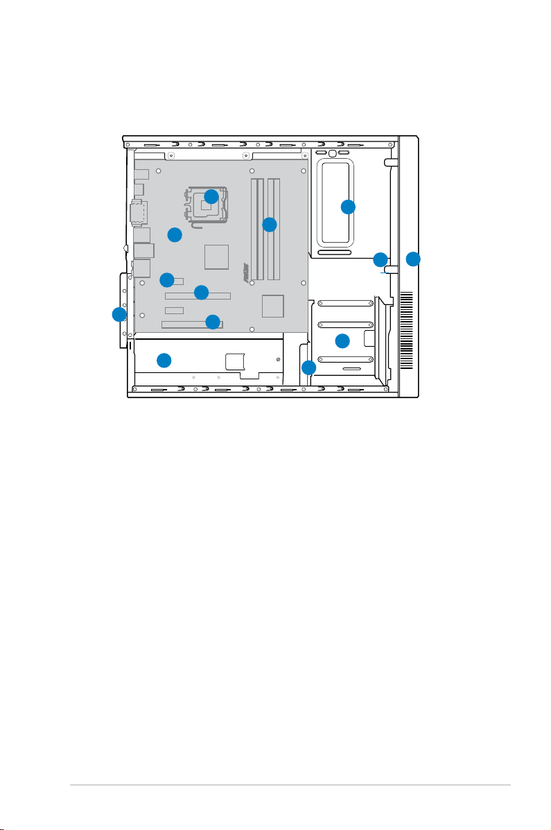
1.4 Internal components
R
The illustration below is the internal view of the system when you remove the side
cover and the chassis support bracket. The installed components are labeled for
your reference.
12
10
9
8
11
6
7
1. 5.25-inch empty optical drive bay
2. Front panel assembly
3. Optical drive lock
4. Hard disk drive bays
5. Hard disk drive lock
6. Power supply unit
7. PCI slots
1
13
4
5
8. PCI Express x16 slot
9. PCI Express x1 slot
10. ASUS motherboard
11. Metal bracket lock
12. LGA775 socket
13. DIMM sockets
2
3
1-7ASUS P3-P5G43
Page 18

1-8 Chapter 1: System introduction
Page 19
Chapter 2
This chapter helps you to power up the
system and install drivers and utilities
from the support CD.
Getting started
Page 20
2.1 Installing an operating system
This motherboard supports Windows® XP/64-bit XP/Vista/64-bit Vista operating
systems (OS). Always install the latest OS version and corresponding updates to
maximize the features of your hardware.
• Motherboard settings and hardware options vary. Use the setup
procedures presented in this chapter for reference only. Refer to your OS
documentation for detailed information.
®
• Make sure that you install the Windows
before installing the drivers for better compatibility and system stability.
XP Service Pack2 or later versions
2.2 Support CD information
The support CD that came with the motherboard package contains the drivers,
software applications, and utilities that you can install to avail all motherboard
features.
The contents of the support CD are subject to change at any time without
notice. Visit the ASUS website (www.asus.com) for updates.
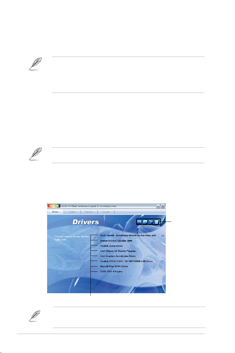
2.2.1 Running the support CD
Place the support CD to the optical drive. The CD automatically displays the
Drivers menu if Autorun is enabled in your computer.
Click an icon to
display support
CD/motherboard
information
Click an item to install
If Autorun is NOT enabled in your computer, browse the contents of the support
CD to locate the le ASSETUP.EXE from the BIN folder. Double-click the
ASSETUP.EXE to run the CD.
2-2 Chapter 2: Getting started
Page 21
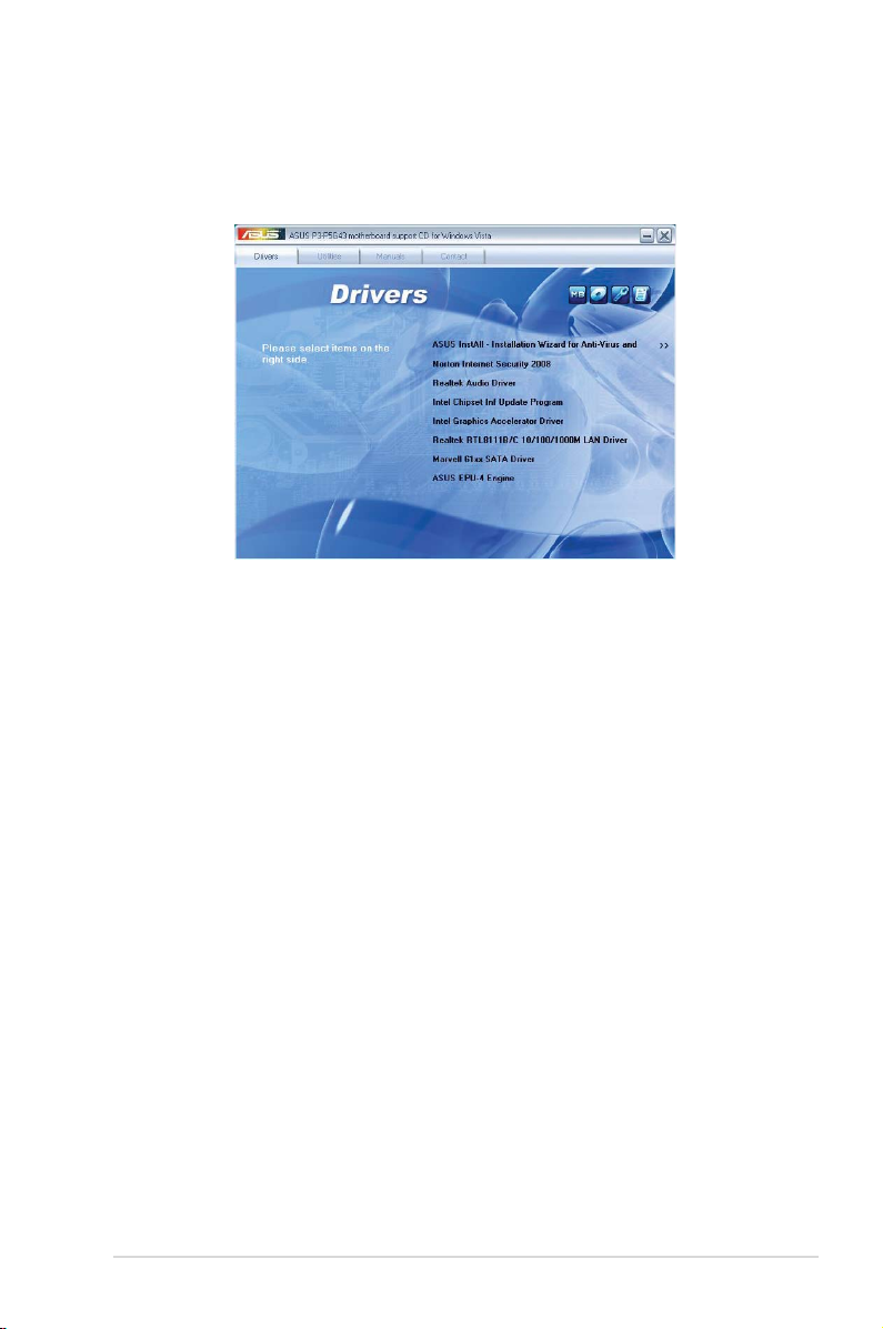
2.2.2 Drivers menu
The drivers menu shows the available device drivers if the system detects installed
devices. Install the necessary drivers to activate the devices.
ASUS InstAll- Installation Wizard for Anti-Virus and Drivers
Installs the ASUS InstAll- Installation Wizard for Anti-Virus and Drivers.
Norton Internet Security 2008
Installs the Norton Internet Security 2008.
Realtek Audio Driver
Install the Realtek® Audio Driver.
Intel(R) Chipset Inf Update Program
Installs the Intel® chipset Inf update program.
Intel(R) Graphics Accelerator Driver
Installs the Intel® graphics accelerator driver.
Realtek RTL8111B/C 10/100/1000M LAN Driver
Installs the Realtek® RTL8111B/C 10/100/1000M LAN driver.
Marvell 61xx SATA Driver
Installs the Marvell 61xx SATA driver.
ASUS EPU-4 Engine
Installs the ASUS EPU-4 Engine driver and utilities.
ASUS P3-P5G43 2-3
Page 22
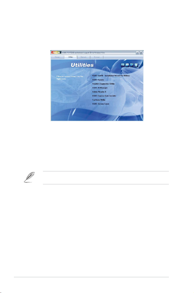
2.2.3 Utilities menu
The Utilities menu shows the applications and other software that the motherboard
supports.
ASUS InstAll-Installation Wizard for Utilities
Installs all of the utilities through the Installation Wizard.
ASUS Update
Allows you to download the latest version of the BIOS from the ASUS website.
Before using the ASUS Update, make sure that you have an Internet connection
so that you can connect to the ASUS website.
Realtek Diagnostics Utility
Installs the Realtek® Diagnostics Utility.
ASUS AI Manager
Installs the ASUS AI Manager.
Adobe Reader 8
Installs the Adobe® Reader 8 that allows you to open, view, and print documents in Portable
Document Format (PDF).
ASUS Express Gate Installer
Installs the ASUS Express Gate application.
2-4 Chapter 2: Getting started
Page 23

FarStone Utility
Installs the FarStone Utility.
ASUS Screen Saver
Installs the ASUS screensaver.
2.2.4 Manual menu
The Manual menu contains a list of supplementary user manuals. Click an item to
open the folder of the user manual.
Most user manual les are in Portable Document Format (PDF). Install the
Adobe® Reader from the Utilities menu before opening a user manual le.
ASUS P3-P5G43 2-5
Page 24

2.2.5 ASUS contact information
Click the Contact tab to display the ASUS contact information.
2-6 Chapter 2: Getting started
Page 25

2.2.6 Other information
The icons on the top right corner of the screen give additional information on the
motherboard and the contents of the support CD. Click an icon to display the
specied information.
Motherboard Info
Displays the general specications of the motherboard.
Motherboard
ASUSTeK Computer INC.
Manuafacture
P3-P5G43
Product Name
x.xx
Version
BIOS
American Megatrends. Inc.
Vendor
0306
BIOS Version
09/19/2008
BIOS Release Date
BIOS ROM Size
1024 KB
Browse this CD
Displays the support CD contents in graphical format.
P3-P5G43
ASUS P3-P5G43 2-7
Page 26

Technical support Form
Displays the ASUS Technical Support Request Form that you have to ll out when
requesting technical support.
Filelist
Displays the contents of the support CD and a brief description of each in text
format.
2-8 Chapter 2: Getting started
Page 27

Chapter 3
This chapter gives information about
the motherboard that comes with the
system. This chapter includes the
motherboard layout, jumper settings,
and connector locations.
Motherboard info
Page 28

3.1 Motherboard overview
R
24.4cm(9.6in)
PCIEX16
PCIEX1_2
PCI1
PCIEX1_1
USB1112 USB910
USBPW9-12
USBPW78
USB78
PS2_USBPW5-6
USBPW1-4
8Mb
BIOS
Super I/O
CR2032 3V
Lithium Cell
CMOS Power
24.4cm(9.6in)
PS/2KBMS
USB56
RTL
81111C
LGA775
CPU_FAN
Intel ICH10
Marvell
6111B2
Intel G43
SATA12
CLRTC
SB_PWR
CD
DDR2 DIMM_A1 (64 bit,240-pin module)
DDR2 DIMM_A2 (64 bit,240-pin module)
DDR2 DIMM_B1 (64 bit,240-pin module)
DDR2 DIMM_B2 (64 bit,240-pin module)
PANEL
JMB381
PRI_EIDE
RTM870T-954
ALC1200
AAFP
SPDIF_OUT
CHASSIS
LAN1_USB12
1394
ESATA
USB34
AUDIO
HDMI
VGA_DVI
CHA_FAN
EATXPWR
ATX12V
Motherboard layout
3-2
Refer to section 1.3 Rear Panel and 3.3.2 Internal Connectors for more
information about rear panel connectors and internal connectors.
Chapter 3: Motherboard info
Page 29

Clear RTC RAM
R
CLRTC
Normal
Clear CMOS
(Default)
1 2 2 3
3.2 Jumpers
1. Clear RTC RAM (3-pin CLRTC)
This jumper allows you to clear the Real Time Clock (RTC) RAM in
CMOS. You can clear the CMOS memory of date, time, and system setup
parameters by erasing the CMOS RTC RAM data. The onboard button
cell battery powers the RAM data in CMOS, which include system setup
information such as system passwords.
To erase the RTC RAM:
1. Turn OFF the computer and unplug the power cord.
2. Move the jumper cap from pins 1-2 (default) to pins 2-3. Keep the cap on
pins 2-3 for about 5-10 seconds, then move the cap back to pins 1-2.
3. Plug the power cord and turn ON the computer.
4. Hold down the
<Del> key during the boot process and enter BIOS setup
to re-enter data.
Except when clearing the RTC RAM, never remove the cap on CLRTC jumper
default position. Removing the cap will cause system boot failure!
• If the steps above do not help, remove the onboard battery and move the
jumper again to clear the CMOS RTC RAM data. After clearing the CMOS,
reinstall the battery.
• You do not need to clear the RTC when the system hangs due to
overclocking. For system failure due to overclocking, use the CPU
Parameter Recall (C.P.R.) feature. Shut down and reboot the system, then
the BIOS automatically resets parameter settings to default values.
ASUS P3-P5G43
3-3
Page 30

2. USB device wake-up (3-pin PS2_USBPW5-6, USBPW1-4, USBPW78,
USB Device Wake Up
R
3
2
2
1
USBPW1-4
+5
V
(D
e
fa
u
lt
)
+5VSB
3
2
2
1
PS2_USBPW5-6
+5
V
(D
e
fa
u
lt
)
+5VSB
3
2
2
1
USBPW9-12
+5
V
(D
e
fault)
+5VSB
3
2
2
1
USBPW78
+5
V
(D
e
fault
)
+5VSB
USBPW9-12)
These jumpers allow you to wake up the computer from S1 mode (CPU
stopped, DRAM refreshed, system running in low power mode) using the
connected USB device. Set this jumper to pins 2-3 (+5VSB) to wake up the
computer from S3 and S4 modes (no power to CPU, DRAM in slow refresh,
power supply in reduced power mode).
• The USB device wake-up feature requires a power supply that can
provide 500mA on the +5VSB lead for each USB port; otherwise,
the system would not power up.
• The total current consumed must NOT exceed the power supply
capability (+5VSB) whether under normal condition or in sleep mode.
3-4
Chapter 3: Motherboard info
Page 31

3.3 Connectors
Digital Audio Connector
R
+5V
SPDIFOUT
GND
SPDIF_OUT
Internal Audio Connector
R
CD
(black)
Right Audio Channel
Left Audio Channel
Ground
Ground
3.3.1 Rear panel connectors
Refer to section “1.3 Rear panel” for a description of the rear panel I/O ports.
3.3.2 Internal connectors
1. Digital Audio connector (4-1 pin SPDIF_OUT)
This connector is for the S/PDIF audio module to allow digital sound output.
Connect one end of the S/PDIF audio cable to this connector and the other
end to the S/PDIF module.
The S/PDIF out module is purchased separately.
2. Optical drive audio connector (4-pin CD)
These connectors allow you to receive stereo audio input from sound sources
such as a CD-ROM, TV tuner, or MPEG card.
ASUS P3-P5G43
3-5
Page 32

3. IDE connector (40-1 pin PRI_EIDE)
IDE Connector
R
NOTE: Orient the red markings
(usually zigzag) on the ID
ribbon cable to PIN 1.
PRI_EIDE
PIN1
The onboard IDE connector is for the Ultra DMA 133/100/66/33 signal cable.
There are three connectors on each Ultra DMA 133/100/66/33 signal cable:
blue, black, and gray. Connect the blue connector to the motherboard’s IDE
connector, then select one of the following modes to congure your device.
Drive jumper setting Mode of
Cable connector
device(s)
Single device Cable-Select or Master - Black
Two devices Cable-Select Master
Black
Slave Gray
Master Master Black or gray
Slave Slave
• Pin 20 on the IDE connector is removed to match the covered hole on the
Ultra DMA cable connector. This prevents incorrect insertion when you
connect the IDE cable.
• Use the 80-conductor IDE cable for Ultra DMA 133/100/66/33 IDE devices.
If any device jumper is set as “Cable-Select,” make sure all other device
jumpers have the same setting.
3-6
Chapter 3: Motherboard info
Page 33

4. Serial ATA connectors (7-pin SATA1 [red], SATA2 [red])
SATA Connectors
R
GND
RSAT
A_TXP1
RSAT
A_TXN1
GND
RSAT
A_RXP1
RSAT
A_RXN1
GND
SATA1
GND
RSAT
A_TXP2
RSAT
A_TXN2
GND
RSAT
A_RXP2
RSAT
A_RXN2
GND
SATA2
These connectors are for the Serial ATA signal cables for Serial ATA hard disk
drives.
Follow any of the methods below
to connect a SATA device:
• Connect the Right-angle
side of the SATA cable to
SATA1 connector and the
other side to a SATA device.
• Connect the Straight-out
side of the SATA cable to
SATA2 connector and the
other side to a SATA device.
Right-angle side
Straight-out side
ASUS P3-P5G43
3-7
Page 34

5. USB connectors (10-1 pin USB78, USB90, USB1112)
R
USB 2.0 Connectors
USB78
USB+5V
USB_P8-
USB_P8+
GND
NC
USB+5V
USB_P7-
USB_P7+
GND
1
USB910
USB+5V
USB_P10-
USB_P10+
GND
NC
USB+5V
USB_P9-
USB_P9+
GND
1
USB1112
USB+5V
USB_P12-
USB_P12+
GND
NC
USB+5V
USB_P11-
USB_P11+
GND
1
These connectors are for USB 2.0 ports. Connect the USB module cable
to any of these connectors, then install the module to a slot opening at the
back of the system chassis. These USB connectors comply with USB 2.0
specication that supports up to 480 Mbps connection speed.
Never connect a 1394 cable to the USB connectors. Doing so will damage the
motherboard!
The USB module is purchased separately.
3-8
Chapter 3: Motherboard info
Page 35

6. CPU and chassis fan connectors (4-pin CPU_FAN, 3-pin CHA_FAN,)
Fan Connectors
R
CPU_FAN
GND
CPU FAN PWR
CPU FAN IN
CPU FAN PWM
CHA_FAN
GND
Rotation
+12V
The fan connectors support cooling fans of 350 mA ~ 2000 mA (24 W max.)
or a total of 1 A ~ 7 A (84 W max.) at +12V. Connect the fan cables to the
fan connectors on the motherboard, making sure that the black wire of each
cable matches the ground pin of the connector.
Do not forget to connect the fan cables to the fan connectors. Insufcient air
ow inside the system may damage the motherboard components. These are
not jumpers! Do not place jumper caps on the fan connectors!
Only the CPU-FAN connector support the ASUS Advanced Q-Fan feature.
ASUS P3-P5G43
3-9
Page 36

Front Panel Audio Connector
R
SENSE2_RETUR
PORT1L
PORT1R
PORT2R
SEBSE_SEND
PORT2L
SENSE1_RETUR
PRESENSE#
GND
AAFP
Legacy AC’97
compliant definition
NC
MIC2
Line out_R
Line out_L
NC
NC
MICPWR
NC
AGND
HD-audio-compliant
pin definition
7. Chassis intrusion connector (4-1 pin CHASSIS)
Intrusion Connector
R
CHASSIS
+5VSB_MB
Chassis Signal
GND
(Default)
This connector is for a chassis-mounted intrusion detection sensor or switch.
Connect one end of the chassis intrusion sensor or switch cable to this
connector. The chassis intrusion sensor or switch sends a high-level signal to
this connector when a chassis component is removed or replaced. The signal
is then generated as a chassis intrusion event.
By default , the pin labeled “Chassis Signal” and “ Ground” are shorted with
a jumper cap. Remove the jumper caps only when you intend to use the
chassis intrusion detection feature.
8. Front panel audio connector (10-1 pin AAFP)
This connector is for a chassis-mounted front panel audio I/O module that
supports either HD Audio or legacy AC’97 audio standard.
•
We recommend that you connect a high-denition front panel audio
module to this connector to avail of the motherboard’s high-denition audio
capability.
• By default, this connector is set to HD Audio. If you want to connect a High
Denition front panel audio module to this connector, set the Front Panel
Support Type item in the BIOS to [HD Audio]. See section “4.4.3 Chipset”
for details.
3-10
Chapter 3: Motherboard info
Page 37

9. ATX power connectors (24-pin EATXPWR, 4-pin ATX12V)
ATX Power Connector
R
EATXPWR
+3 Volts
+3 Volts
Ground
+5 Volts
+5 Volts
Ground
Ground
Power OK
+5V Standby
+12 Volts
-5 Volts
+5 Volts
+3 Volts
-12 Volts
Ground
Ground
Ground
PSON#
Ground
+5 Volts
+12 Volts
+3 Volts
+5 Volts
Ground
ATX12V
GND
+12V DC
GND
+12V DC
These connectors are for ATX power supply plugs. The power supply plugs
are designed to t these connectors in only one orientation. Find the proper
orientation and push down rmly until the connectors completely t.
•
For a fully congured system, we recommend that you use a power supply
unit (PSU) that complies with ATX 12 V Specication 2.0 (or later version)
and provides a minimum power of 400 W.
• Do not forget to connect the 4-pin ATX12V power plug; otherwise, the
system will not boot.
• Use of a PSU with a higher power output is recommended when
conguring a system with more power-consuming devices. The system
may become unstable or may not boot up if the power is inadequate.
• The ATX 12 V Specication 2.0-compliant (400W) PSU has been tested to
support the motherboard power requirements.
ASUS P3-P5G43
3-11
Page 38

10. System panel connector (20-8 pin F_PANEL)
System Panel Connector
R
* Requires an ATX power supply
NEL
PLED-
PWR
+5V
Speaker
Ground
RESET
Ground
Reset
Ground
Ground
PWRSW
PLED+
IDE_LED-
IDE_LED+
IDE_LED
PLED SPEAKER
PA
This connector supports several chassis-mounted functions.
• System power LED (2-pin PLED)
This 2-pin connector is for the system power LED. Connect the chassis
power LED cable to this connector. The system power LED lights up when
you turn on the system power, and blinks when the system is in sleep mode.
• Hard disk drive activity LED (2-pin IDE_LED)
This 2-pin connector is for the HDD Activity LED. Connect the HDD Activity
LED cable to this connector. The IDE LED lights up or ashes when data is
read from or written to the HDD.
• System warning speaker (4-pin SPEAKER)
The 4-pin connector is for the chasiss-mounted system warning speaker. The
speaker allows you to hear system beeps and warnings.
• ATX power button/soft-off button (2-pin PWRSW)
This connector is for the system power button. Pressing the power button
turns the system on or puts the system in sleep or soft-off mode depending
on the BIOS settings. Pressing the power switch for more than four seconds
while the system is ON turns the system OFF.
• Reset button (2-pin RESET)
This 2-pin connector is for the chassis-mounted reset button for system
reboot without turning off the system power.
3-12
Chapter 3: Motherboard info
Page 39

Chapter 4
This chapter tells how to change
the system settings through the BIOS
Setup menus. Detailed descriptions
of the BIOS parameters are also
provided.
ASUS P3-P5G43
BIOS setup
Page 40

4.1 Managing and updating your BIOS
The following utilities allow you to manage and update the motherboard Basic
Input/Output System (BIOS) setup.
1.
ASUS EZ Flash 2: Updates the BIOS in DOS mode using a oppy disk or a
USB ash disk.
2. ASUS AFUDOS: Updates the BIOS in DOS mode using a bootable oppy
disk.
ASUS CrashFree BIOS 3: Updates the BIOS using a oppy disk, a USB
3.
ash disk, or the motherboard support DVD when the BIOS le fails or gets
corrupted.
ASUS Update: Updates the BIOS in Windows® environment.
4.
Refer to the corresponding sections for details on these utilities.
Save a copy of the original motherboard BIOS le to a bootable oppy disk or
a USB ash disk in case you need to restore the BIOS in the future. Copy the
original motherboard BIOS using the ASUS Update or AFUDOS utilities.
4.1.1 Creating a bootable oppy disk
1. Do either of the following to create a bootable oppy disk.
DOS environment
a. Insert a 1.44MB oppy disk into the drive.
b. At the DOS prompt, type
format A:/S then press <Enter>.
Windows® XP environment
a. Insert a 1.44 MB oppy disk to the oppy disk drive.
b. Click
c. Select the 3 1/2 Floppy Drive icon.
d. Click
Disk window appears.
e. Select
then click Start.
4-2 Chapte 4: BIOS setup
Start from the Windows® desktop, then select My Computer.
File from the menu, then select Format. A Format 3 1/2 Floppy
Create an MS-DOS startup disk from the format options eld,
Page 41

Windows® Vista environment
a. Insert a formatted, high density 1.44 MB oppy disk to the oppy disk
drive.
b. Click
c. Right-click Floppy Disk Drive then click
from the Windows® desktop, then select Computer.
Format to display the
Format 3 1/2 Floppy dialog box.
d. Select the
e. Click
Create an MS-DOS startup disk check box.
Start.
2. Copy the original or the latest motherboard BIOS le to the bootable oppy
disk.
ASUS P3-P5G43 4-3
Page 42

4.1.2 ASUS EZ Flash 2 utility
The ASUS EZ Flash 2 feature allows you to update the BIOS without having to go
through the long process of booting from a oppy disk and using a DOS-based
utility. The EZ Flash 2 utility is built-in the BIOS chip so it is accessible by pressing
<Alt> + <F2> during the Power-On Self Tests (POST).
To update the BIOS using EZ Flash 2:
1. Visit the ASUS website (www.asus.com) to download the latest BIOS le for
the motherboard.
2. Save the BIOS le to a oppy disk or a USB ash disk, then restart the
system.
3. You can launch the EZ Flash 2 in two ways.
(1) Insert the oppy disk / USB ash disk that contains the BIOS le to the
oppy disk drive or the USB port.
Press
(2) Enter BIOS setup program. Go to the
<Alt> + <F2> during POST to display the following.
ASUSTek EZ Flash 2 BIOS ROM Utility V3.25
FLASH TYPE: MXIC 25L8005
Current ROM
BOARD: P5QL-EM P3-P5G43
VER: 0306 (H:00 B:02)
DATE: 09/19/2008
PATH: A:\
A:
Note
[Ente r] S elec t or Load [ Tab] S witc h [V ] Dr ive In fo
[Up/Down/Home/End] Move [B] Backup [ESC] Exit
Update ROM
BOARD: Unknown
VER: Unknown
DATE: Unknown
Tools menu then select EZ Flash
2 and press <Enter>.
You can switch between drives by pressing
<Tab> before the correct le
is found. Then press <Enter>.
4. When the correct BIOS le is found, EZ Flash 2 performs the BIOS update
process and automatically reboots the system when done.
• This function can support devices such as USB ash disks, or oppy disks
with
FAT 32/16
• DO NOT shut down or reset the system while updating the BIOS to prevent
system boot failure!
format and single partition only.
4-4 Chapte 4: BIOS setup
Page 43

4.1.3 AFUDOS utility
The AFUDOS utility allows you to update the BIOS le in DOS environment using
a bootable oppy disk with the updated BIOS le. This utility also allows you to
copy the current BIOS le that you can use as backup when the BIOS fails or gets
corrupted during the updating process.
Copying the current BIOS
To copy the current BIOS le using the AFUDOS utility:
• Ensure that the oppy disk is not write-protected and has at least 1.2MB
free space to save the le.
• The succeeding BIOS screens are for reference only. The actual BIOS
screen displays may not be same as shown.
1. Copy the AFUDOS utility (afudos.exe) from the motherboard support DVD to
the bootable oppy disk you created earlier.
2. Boot the system in DOS mode, then at the prompt type:
afudos /o[lename]
where the [lename] is any user-assigned lename not more than eight
alphanumeric characters for the main lename and three alphanumeric
characters for the extension name.
A:\>afudos /oOLDBIOS1.rom
Main lename Extension name
3. Press
<Enter>. The utility copies the current BIOS le to the oppy disk.
A:\>afudos /oOLDBIOS1.rom
AMI Firmware Update Utility - Version 1.19(ASUS V2.07(03.11.24BB))
Copyright (C) 2002 American Megatrends, Inc. All rights reserved.
Reading ash ..... done
Write to le...... ok
A:\>
The utility returns to the DOS prompt after copying the current BIOS le.
ASUS P3-P5G43 4-5
Page 44

Updating the BIOS le
To update the BIOS le using the AFUDOS utility:
1. Visit the ASUS website (www.asus.com) and download the latest BIOS le for
the motherboard. Save the BIOS le to a bootable oppy disk.
Write the BIOS lename on a piece of paper. You need to type the exact BIOS
lename at the DOS prompt.
2. Copy the AFUDOS utility (afudos.exe) from the motherboard support DVD to
the bootable oppy disk you created earlier.
3. Boot the system in DOS mode, then at the prompt type:
afudos /i[lename]
where [lename] is the latest or the original BIOS le on the bootable oppy
disk.
A:\>afudos /iP3P5G43.ROM
4. The utility veries the le and starts updating the BIOS.
A:\>afudos /iP3P5G43.ROM
AMI Firmware Update Utility - Version 1.19(ASUS V2.07(03.11.24BB))
Copyright (C) 2002 American Megatrends, Inc. All rights reserved.
WARNING!! Do not turn off power during ash BIOS
Reading le ....... done
Reading ash ...... done
Advance Check ......
Erasing ash ...... done
Writing ash ...... 0x0008CC00 (9%)
Do not shut down or reset the system while updating the BIOS to prevent
system boot failure!
5. The utility returns to the DOS prompt after the BIOS update process is
completed. Reboot the system from the hard disk drive.
A:\>afudos /iP3P5G43.ROM
AMI Firmware Update Utility - Version 1.19(ASUS V2.07(03.11.24BB))
Copyright (C) 2002 American Megatrends, Inc. All rights reserved.
WARNING!! Do not turn off power during ash BIOS
Reading le ....... done
Reading ash ...... done
Advance Check ......
Erasing ash ...... done
Writing ash ...... done
Verifying ash .... done
Please restart your computer
A:\>
4-6 Chapte 4: BIOS setup
Page 45

4.1.4 ASUS CrashFree BIOS 3 utility
The ASUS CrashFree BIOS 3 is an auto recovery tool that allows you to restore
the BIOS le when it fails or gets corrupted during the updating process. You can
update a corrupted BIOS le using the motherboard support DVD , the oppy disk,
or the USB ash disk that contains the updated BIOS le.
• Prepare the motherboard support DVD, the oppy disk, or the USB ash
disk containing the updated motherboard BIOS before using this utility.
• Make sure that you rename the original or updated BIOS le in the oppy
disk or the USB ash disk to P3P5G43.ROM.
Recovering the BIOS from a oppy disk
To recover the BIOS from a oppy disk:
1. Turn on the system.
2. Insert the oppy disk with the original or updated BIOS le to the oppy disk
drive.
3. The utility displays the following message and automatically checks the
oppy disk for the original or updated BIOS le.
Bad BIOS checksum. Starting BIOS recovery...
Checking for oppy...
When found, the utility reads the BIOS le and starts ashing the corrupted
BIOS le.
Bad BIOS checksum. Starting BIOS recovery...
Checking for oppy...
Floppy found!
Reading le “P3P5G43.ROM”. Completed.
Start ashing...
DO NOT shut down or reset the system while updating the BIOS! Doing so can
cause system boot failure!
4. Restart the system after the utility completes the updating process.
ASUS P3-P5G43 4-7
Page 46

Recovering the BIOS from the support DVD
To recover the BIOS from the support DVD:
1. Remove any oppy disk from the oppy disk drive, then turn on the system.
2. Insert the support DVD to the optical drive.
3. The utility displays the following message and automatically checks the
oppy disk for the original or updated BIOS le.
Bad BIOS checksum. Starting BIOS recovery...
Checking for oppy...
When no oppy disk is found, the utility automatically checks the optical drive
for the original or updated BIOS le. The utility then updates the corrupted
BIOS le.
Bad BIOS checksum. Starting BIOS recovery...
Checking for oppy...
Floppy not found!
Checking for CD-ROM...
CD-ROM found!
Reading le “P3P5G43.ROM”. Completed.
Start ashing...
4. Restart the system after the utility completes the updating process.
The recovered BIOS may not be the latest BIOS version for this motherboard.
Visit the ASUS website (www.asus.com) to download the latest BIOS le.
Recovering the BIOS from the USB ash disk
To recover the BIOS from the USB ash disk:
1. Insert the USB ash disk that contains BIOS le to the USB port.
2. Turn on the system.
3. The utility will automatically checks the devices for the BIOS le When found,
the utility reads the BIOS le and starts ashing the corrupted BIOS le.
4. Restart the system after the utility completes the updating process.
• Only the USB ash disk with FAT 32/16 format and single partition can
support ASUS CrashFree BIOS 3. The device size should be smaller than
8GB.
• DO NOT shut down or reset the system while updating the BIOS! Doing so
can cause system boot failure!
4-8 Chapte 4: BIOS setup
Page 47

4.1.5 ASUS Update utility
The ASUS Update is a utility that allows you to manage, save, and update the
motherboard BIOS in Windows® environment. The ASUS Update utility allows you
to:
• Save the current BIOS le
• Download the latest BIOS le from the Internet
• Update the BIOS from an updated BIOS le
• Update the BIOS directly from the Internet, and
• View the BIOS version information.
This utility is available in the support DVD that comes with the motherboard
package.
ASUS Update requires an Internet connection either through a network or an
Internet Service Provider (ISP).
Installing ASUS Update
To install ASUS Update:
1. Place the support DVD in the optical drive. The
2. Click the
Utilities tab, then click Install ASUS Update. See page 2-4 for the
Drivers menu appears.
Utilities screen menu.
3. Follow the onscreen instructions to complete the installation.
Quit all Windows® applications before you update the BIOS using this utility.
ASUS P3-P5G43 4-9
Page 48

Updating the BIOS through the Internet
To update the BIOS through the Internet:
1. Launch the ASUS Update utility from the Windows
> Programs > ASUS > ASUSUpdate > ASUSUpdate. The ASUS Update
main window appears.
®
desktop by clicking Start
2. Select Update BIOS from
the Internet option from the
drop-down menu, then click Next.
4-10 Chapte 4: BIOS setup
3. Select the ASUS FTP site nearest
you to avoid network trafc, or
click Auto Select. Click Next.
Page 49

4. From the FTP site, select the BIOS
version that you wish to download.
Click Next.
5. Follow the screen instructions to
complete the update process.
The ASUS Update utility is
capable of updating itself
through the Internet. Always
update the utility to avail all its
features.
Updating the BIOS through a BIOS le
To update the BIOS through a BIOS le:
1. Launch the ASUS Update utility from the Windows® desktop by clicking
> Programs > ASUS > ASUSUpdate > ASUSUpdate. The ASUS Update
main window appears.
2. Select
Update BIOS from a le
option from the drop-down menu,
then click Next.
3. Locate the BIOS le from the Open
window, then click Open.
4. Follow the screen instructions to
P3P5G43.ROM
complete the update process.
P3P5G43
Start
ASUS P3-P5G43 4-11
Page 50

4.2 BIOS setup program
This motherboard supports a programmable rmware chip that you can update
using the provided utility described in section “2.1 Managing and updating your
BIOS.”
Use the BIOS Setup program when you are installing a motherboard, reconguring
your system, or prompted to “Run Setup”. This section explains how to congure
your system using this utility.
Even if you are not prompted to use the Setup program, you can change the
conguration of your computer in the future. For example, you can enable the
security password feature or change the power management settings. This
requires you to recongure your system using the BIOS Setup program so that the
computer can recognize these changes and record them in the CMOS RAM of the
SPI chip.
The rmware chip on the motherboard stores the Setup utility. When you start up
the computer, the system provides you with the opportunity to run this program.
Press <Del> during the Power-On Self-Test (POST) to enter the Setup utility;
otherwise, POST continues with its test routines.
If you wish to enter Setup after POST, reboot the system by doing any of the
following procedures:
• Restart using the OS standard shut-down procedure.
• Press
• Press the reset button on the system chassis.
• Press the power button to turn the system off then back on.
<Ctrl>+<Alt>+<Del> simultaneously.
Using the power button, reset button, or the <Ctrl>+<Alt>+<Del> keys to
force reset from a running operating system can cause damage to your data
or system. We recommend to always shut-down the system properly from the
operating system.
The Setup program is designed to make it as easy to use as possible. Being a
menu-driven program, it lets you scroll through the various sub-menus and make
your selections from the available options using the navigation keys.
• The default BIOS settings for this motherboard apply for most conditions
to ensure optimum performance. If the system becomes unstable after
changing any BIOS settings, load the default settings to ensure system
compatibility and stability. Select the Load Setup Defaults item under the
Exit Menu. See section “4.8 Exit Menu.”
• The BIOS setup screens shown in this section are for reference purposes only,
and may not exactly match what you see on your screen.
• Visit the ASUS website (www.asus.com) to download the latest BIOS le
for this motherboard.
4-12 Chapte 4: BIOS setup
Page 51

4.2.1 BIOS menu screen
Menu bar Conguration eldsMenu items
System Time [00: 38 : 56]
System Date [Mon 09/27/2008]
SATA1 : [Not Detected]
SATA2 : [Not Detected]
Storage Conguration
System Information
General help
Use [ENTER], [TAB]
or [SHIFT-TAB] to
select a eld.
Use [+] or [-] to
congure system time.
Navigation keysSub-menu items
4.2.2 Menu bar
The menu bar on top of the screen has the following main items:
Main For changing the basic system conguration
Advanced For changing the advanced system settings
Power For changing the advanced power management (APM)
conguration
Boot For changing the system boot conguration
Tools For conguring options for special functions
Exit For selecting the exit options and loading default
settings
To select an item on the menu bar, press the right or left arrow key on the keyboard
until the desired item is highlighted.
4.2.3 Navigation keys
At the bottom right corner of a menu screen are the navigation keys for that
particular menu. Use the navigation keys to select items in the menu and change
the settings.
Some of the navigation keys differ from one screen to another.
ASUS P3-P5G43 4-13
Page 52

4.2.4 Menu items
The highlighted item on the menu bar
displays the specic items for that
menu. For example, selecting Main
shows the Main menu items.
The other items (Advanced, Power,
Boot, Tool, and Exit) on the menu bar
have their respective menu items.
4.2.5 Sub-menu items
A solid triangle before each item on any menu screen means that the iteam has a
sub-menu. To display the sub-menu, select the item and press <Enter>.
System Time [11:56:54]
System Date [Wed 04/16/2008]
SATA1 [Not Detected]
SATA2 [Not Detected]
Storage Conguration
System Information
Main menu items
Use [ENTER], [TAB]
or [SHIFT-TAB] to
select a eld.
Use [+] or [-] to
congure system
time.
4.2.6 Conguration elds
These elds show the values for the menu items. If an item is user- congurable,
you can change the value of the eld opposite the item. You cannot select an item
that is not user-congurable.
A congurable eld is enclosed in brackets, and is highlighted when selected. To
change the value of a eld, select it then press <Enter> to display a list of options.
Refer to “4.2.7 Pop-up window.”
4.2.7 Pop-up window
Select a menu item then press <Enter> to display a pop-up window with the
conguration options for that item.
4.2.8 Scroll bar
A scroll bar appears on the right side of a menu screen when there are items that
do not t on the screen. Press the
<Up> / <Down> arrow keys or <Page
Up> / <Page Down> keys to display
the other items on the screen.
4.2.9 General help
At the top right corner of the menu
screen is a brief description of the
selected item.
4-14 Chapte 4: BIOS setup
Pop-up window
Scroll bar
Page 53

4.3 Main menu
When you enter the BIOS Setup program, the Main menu screen appears, giving
you an overview of the basic system information.
Refer to section “4.2.1 BIOS menu screen” for information on the menu screen
items and how to navigate through them.
Main Advanced Power Boot Tools Exit
System Time [19:34:30]
System Date [Mon 09/27/2008]
SATA 1 :[Not Detected]
SATA 2 :[Not Detected]
Storage Conguration
System Information
v02.58 (C)Copyright 1985-2008, American Megatrends, Inc.
BIOS SETUP UTILITY
4.3.1 System Time [xx:xx:xx]
Allows you to set the system time.
4.3.2 System Date [Day xx/xx/xxxx]
Allows you to set the system date.
Use [ENTER], [TAB]
or [SHIFT-TAB] to
select a eld.
Use [+] or [-] to
congure system
Time.
Select Screen
Select Item
Change Field
+-
Tab Select Field
F1 General Help
F10 Save and Exit
ESC Exit
ASUS P3-P5G43 4-15
Page 54

4.3.3 SATA 1~2
Select Screen
Select Item
+- Change Option
F1 General Help
F10 Save and Exit
ESC Exit
While entering Setup, the BIOS automatically detects the presence of SATA
devices. There is a separate sub-menu for each SATA device. Select a device item
then press <Enter> to display the IDE device information.
SATA 1
Device : Not Detected
Type [Auto]
LBA/Large Mode [Auto]
Block(Multi-Sector Transfer) M [Auto]
PIO Mode [Auto]
DMA Mode [Auto]
SMART Monitoring [Auto]
32Bit Data Transfer [Enabled]
v02.58 (C)Copyright 1985-2008, American Megatrends, Inc.
Select the type of
device connected to the
system.
The BIOS automatically detects the values opposite the dimmed items (Device,
Vendor, Size, LBA Mode, Block Mode, PIO Mode, Async DMA, Ultra DMA, and
SMART monitoring). These values are not user-congurable. These items show
N/A if no IDE device is installed in the system.
Type [Auto]
Selects the type of IDE drive. Setting to Auto allows automatic selection of the
appropriate IDE device type. Select CDROM if you are specically conguring a
CD-ROM drive. Select ARMD (ATAPI Removable Media Device) if your device
is either a ZIP, LS-120, or MO drive. Conguration options: [Not Installed] [Auto]
[CDROM] [ARMD]
LBA/Large Mode [Auto]
Enables or disables the LBA mode. Setting to Auto enables the LBA mode if the
device supports this mode, and if the device was not previously formatted with LBA
mode disabled. Conguration options: [Disabled] [Auto]
Block (Multi-Sector Transfer) M [Auto]
Enables or disables data multi-sectors transfers. When set to Auto, the data
transfer from and to the device occurs multiple sectors at a time if the device
supports multi-sector transfer feature. When set to [Disabled], the data transfer
from and to the device occurs one sector at a time. Conguration options:
[Disabled] [Auto]
4-16 Chapte 4: BIOS setup
Page 55

PIO Mode [Auto]
Selects the PIO mode. Conguration options: [Auto] [0] [1] [2] [3] [4]
DMA Mode [Auto]
Selects the DMA mode. Conguration options: [Auto]
SMART Monitoring [Auto]
Enables or disables the S.M.A.R.T. (Self Monitoring and Reporting Technology)
capability of your hard drive. This features allows your system to report read/write
errors of the hard drive and to issue warnings when a third party hardware monitor
utility is installed. Conguration options: [Auto] [Disabled] [Enabled]
32Bit Data Transfer [Enabled]
Enables or disables 32-bit data transfer. Conguration options: [Disabled]
[Enabled]
4.3.4 Storage Conguration
The items in this menu allow you to set or change the congurations for the SATA
devices installed in the system. Select an item then press <Enter> if you want to
congure the item.
SATA Conguration
SATA Conguration [Enhanced]
Congure SATA as [IDE]
Hard Disk Write Protect [Disabled]
IDE Detect Time Out (Sec) [35]
Options
Disabled
Compatiable
Enhanced
SATA Conguration [Enhanced]
Conguration options: [Disabled] [Compatible] [Enhanced]
Configure SATA as [IDE]
Sets the conguration for the Serial ATA connectors supported by the
Southbridge chip. Conguration options: [IDE] [AHCI]
Due to Intel chipset driver support regulation, the AHCI mode is not supported in
Windows XP environment. The AHCI mode is only supported by Windows Vista
with OS built-in driver.
Hard Disk Write Protect [Disabled]
Disables or enables device write protection. This will be effective only if device is
accessed throuh BIOS. Conguration option: [Disabled] [Enabled]
ASUS P3-P5G43 4-17
Page 56

IDE Detect Time Out (Sec) [35]
Selects the time out value for detecting ATA/ATAPI devices.
Conguration options: [0] [5] [10] [15] [20] [25] [30] [35]
4.3.5 System Information
This menu gives you an overview of the general system specications. The BIOS
automatically detects the items in this menu.
BIOS Information
Version : 0306
Build Date : 09/19/08
Processor
Type : Intel(R) Core(TM)2 CPU 6300 @ 1.86GHz
Speed : 1866MHz
Count : 2
System Memory
Installed Size: 1024MB
Usable Size: 990MB
BIOS Information
Displays the auto-detected BIOS information.
Processor
Displays the auto-detected CPU specication.
System Memory
Displays the auto-detected system memory.
4-18 Chapte 4: BIOS setup
Page 57

4.4 Advanced menu
The Advanced menu items allow you to change the settings for the CPU and other
system devices.
Take caution when changing the settings of the Advanced menu items. Incorrect
eld values can cause the system to malfunction.
Main Advanced Power Boot Tools Exit
JumperFree Conguration
CPU Conguration
Chipset
Onboard Devices Conguration
USB Conguration
PCIPnP
v02.58 (C)Copyright 1985-2008, American Megatrends, Inc.
BIOS SETUP UTILITY
4.4.1 JumperFree Conguration
Congure System Frequency/Voltage
AI Overclocking [Auto]
DRAM Frequency [Auto]
Memory Over Voltage [Auto]
NB Voltage [Auto]
CPU Voltage [Auto]
Adjust System
frequency/voltage.
Select Screen
Select Item
+- Change Field
Tab Select Field
F1 General Help
F10 Save and Exit
ESC Exit
Select the target CPU
frequency, and the
relevant parameters
will be autoadjusted.
Frequencies higher
than CPU manufacturer
recommends are not
guaranteed to be
stable. If the system
becomes unstable,
return to the
default.
AI Overclocking [Auto]
Allows selection of CPU overclocking options to achieve desired CPU internal
frequency. Select either one of the preset overclocking conguration options:
Manual - allows you to individually set overclocking parameters.
Auto - loads the optimal settings for the system.
Overclock Prole - loads overclocking proles with optimal parameters for
stability when overclocking.
ASUS P3-P5G43 4-19
Page 58

The following item appears only when you set the AI Overclocking item to
[Manual].
CPU Frequency [xxx]
Displays the frequency sent by the clock generator to the system bus and PCI bus.
The value of this item is auto-detected by the BIOS. Use the <+> and <-> keys to
adjust the CPU frequency. You can also type the desired CPU frequency using the
numeric keypad. The values range from 133 to 600. Refer to the table below for
the correct Front Side Bus and CPU External Frequency settings.
FSB / CPU External Frequency Synchronization
Front Side Bus CPU External Frequency
FSB 1333 333 MHz
FSB 1066 266 MHz
FSB 800 200 MHz
The following item appears only when you set the AI Overclocking item to
[Overclock Prole].
Overclock Options [Overclock 5%]
Allows you to select the overclock options. Conguration options: [Overclock 5%]
[Overclock 10%] [Overclock 15%] [Overclock 20%] [Overclock 30%]
4-20 Chapte 4: BIOS setup
Page 59

DRAM Frequency [Auto]
Allows you to set the DDR2 operating frequency. Conguration options: [Auto]
[667 MHz] [800 MHz] [1067MHz]
The following table shows the DRAM Frequency options that appear when the
FSB value is 1333, 1066, and 800.
FSB
Auto 667MHz 800MHz 960MHz 1000MHz 1067MHz 1100MHz 1200MHz
1333 v v v v v
1066 v v v v
800 v v v
Selecting a very high DRAM frequency may cause the system to become
unstable! If this happens, revert to the default setting.
DRAM Frequency
Memory Over Voltage [Auto]
Allows you to adjust Memory Over voltage and each step is 6.25mV
NB Voltage [Auto]
Allows you to set the NB voltage. Conguration options: [Auto] [1.1V] [1.198V]
[1.3V] [1.388V]
Setting a very high voltage may damage the component permanently, and
setting a very low voltage may cause the system to become unstable.
CPU Voltage [Auto]
Allows you to set the CPU VCore voltage. The values range from 0.8500V to 1.55V
with a 0.00625V interval. Conguration options: [Auto]
Setting a very high voltage may damage the component permanently, and
setting a very low voltage may cause the system to become unstable.
ASUS P3-P5G43 4-21
Page 60

4.4.2 CPU Conguration
The items in this menu show the CPU-related information that the BIOS
automatically detects.
Advanced
Congure advanced CPU settings
Module Version: 3D.06
Manufacturer: Intel
Brand String: Intel(R) Core(TM)2 CPU 6300 @ 1.86GHz
Frequency: 1.86GHz
FSB Speed: 1066MHz
Cache L1: 64 KB
Cache L2: 2048 KB
Ratio Status: Unlocked (Max:07.0, Min:06.0)
Ratio Actual Value:7
CPUID: 6F2
CPU Ratio Setting [Auto]
C1E Support [Enabled]
Max CPUID Value Limit [Disabled]
Vanderpool Technology [Enabled]
CPU TM function [Enabled]
Execute Disable Bit [Enabled]
Intel(R) SpeedStep(tm) tech. [Enabled]
v02.58 (C)Copyright 1985-2008, American Megatrends, Inc.
BIOS SETUP UTILITY
Sets the ratio between
CPU Core Clock and the
FSB Frequency.
NOTE: If an invalid
ratio is set in CMOS
then actual and
setpoint values may
differ.
NOTE:
Please Key in ratio
numbers directly!
CPU Ratio Setting [Auto]
Sets the ratio between CPU Core Clock and the FSB frequency. Conguration
options: [Auto].
If an invalid ratio is set in CMOS then actual and setpoint values my differ.
Key in ratio numbers directly.
C1E Support [Enabled]
Allows you to enable or disable Inter CPU Enhanced Halt (C1E) function, a
CPU power-saving function in system halt state. When enabled, the CPU core
frequency and voltage will be reduced during the system halt state to decrease
power consumption. Conguration options: [Disabled] [Enabled]
Max CPUID Value Limit [Disabled]
Allows you to determine whether to limit CPUID maximum value. Set this item to
[Disabled] for Windows XP operating system; set this item to [Enabled] for legacy
operating system such as Windows NT4.0. (Default: Disabled)
Conguration options: [Disabled] [Enabled]
4-22 Chapte 4: BIOS setup
Page 61

Vanderpool Technology [Enabled]
Enables or disables Intel® Virtualization Technology. Virtualization enhanced by
Intel® Virtualization Technology allows a platform to run multiple operating systems
and applications in independent partitons. With virtualization, one computer
system can function as multiple virtual systems. Conguration options: [Enabled]
[Disabled]
CPU TM function [Enabled]
Enables or disables Intel® CPU Thermal Monitor (TM) function, a CPU overheating
protection function. When enabled, the CPU core frequency and voltage are
reduced when the CPU overheats. Conguration options: [Disabled] [Enabled]
Execute Disable Bit [Enabled]
Enables or disables Intel® Execute Disable Bit function. This function enhance
protection of your computer, reducing exposure to viruses and malicious
buffer overow attacks when working with its supporting software and system.
Conguration options: [Disabled] [Enabled]
The following item appears only when you installed an Intel® Pentium® 4 or later
CPU that supports the Enhanced Intel SpeedStep® Technology (EIST).
Intel® SpeedStep™ Technology [Enabled]
Allows you to use the Enhanced Intel® SpeedStep® Technology. When set to
[Enabled], you can adjust the system power settings in the operating system to
use the EIST feature. Set this item to [Disabled] if you do not want to use the
EIST. Conguration options: [Enabled] [Disabled]
ASUS P3-P5G43 4-23
Page 62

4.4.3 Chipset
The Chipset menu allows you to change the advanced chipset settings. Select an
item then press <Enter> to display the sub-menu.
Advanced Chipset Settings
WARNING: Setting wrong values in below sections
may cause system to malfunction.
North Bridge Conguration
South Bridge Conguration
Congure North Bridge
features.
North Bridge Conguration
North Bridge Chipset Conguration
Memory Remap Feature [Enabled]
Congure DRAM Timing by SPD [Enabled]
Initiate Graphic Adapter [PEG/PCI]
IGD Graphics Mode Select [Enabled, 32MB]
GTT Graphics Memory Size [No VT mode, 2MB]
DVMT Mode Select [DVMT Mode]
DVMT Memory [256MB]
Protect Audio Video Path Mode [Lite]
Options
Options
128MB
256MB
Memory Remap Feature [Disabled]
Allows you to enable or disable the remapping of overlapped PCI memory above
the total physical memory. We recommend that you set this item to Enabled when
you install 4GB memory. Conguration options: [Enabled] [Disabled]
Congure DRAM Timing by SPD [Enabled]
Allows you to enable or disable congurating DRAM Timing by SPD. Conguration
options: [Enabled] [Disabled]
Initiate Graphic Adapter [PEG/PCI]
Allows you to select the graphics controller as the primary boot device.
Conguration options: [IGD] [PCI/IGD] [PCI/PEG] [PEG/IGD][PEG/PCI]
4-24 Chapte 4: BIOS setup
Page 63

IGD Graphics Mode Select [Enabled, 32MB]
Sets the IGD graphics mode.
Conguration options: [Disabled] [Enabled, 32MB] [Enabled, 64MB] [Enabled,
128MB]
DVMT Mode Select [DVMT Mode]
Allows you to select the graphics memory type.
Conguration options: [DVMT Mode]
DVMT Memory [256MB]
Configuration options: [128MB] [256MB] [Maximum DVMT]
This option only appears when installing 1GB DDR2 DIMMs into the DIMM
sockets.
Protect Audio Video Path Mode [Lite]
Allows you to set PAVP mode.
Conguration options: [Disabled] [Lite] [Paranoid]
To use the High-Bandwidth Digital Content Protection (HDCP) function, set this
option to either [Lite] or [Paranoid]. If you select Paranoid Mode, the system
reserves 96MB for playing and storing the decrypted contents. The operation
system and other programs cannot use this reserved memory, and Vista Aero
(DWM) is disabled.
Feature PAVP Lite PAVP Paranoid
Compressed video buffer is encrypted Yes Yes
HW 128-bit AES decryption Yes Yes
Protected memory (96MB reserved during boot) No Yes
ASUS P3-P5G43 4-25
Page 64

South Bridge Conguration
South Bridge Chipset Conguration
Audio Controller [Enabled]
Front Panel Type [HD Audio]
SPDIF_OUT Mode Setting [SPDIF Output]
Options
Enabled
Disabled
Options
Audio Controller [Enabled]
Allows you to set the audio controller. Conguration options: [Enabled] [Disabled]
Front Panel Support Type [HD Audio]
Allows you to select the front panel support type. If High Denition Audio
Front Panel used, please set HD Audio mode. Conguration options: [AC97]
[HD Audio]
SPDIF_OUT Mode Setting [SPDIF Output]
Allows you to select SPDIF_OUT mode setting. Conguration options: [HDMI
Output] [SPDIF Output]
4-26 Chapte 4: BIOS setup
Page 65

2.4.4 Onboard Devices Conguration
Onboard Device Conguration
Onboard LAN [Enabled]
LAN Option ROM [Disabled]
Marvell IDE controller [Enabled]
1394 Controller [Enabled]
Onboard PCIEX GbE LAN_
Enable/Disable
Onboard LAN [Enabled]
Allows you to enable or disable the onboard LAN controller.
Conguration options: [Enabled] [Disabled]
LAN Option ROM [Disabled]
Allows you to enable or disable the LAN option ROM in the onboard LAN
controller. This item appears only when the Onboard LAN item is set to
Enabled. Conguration options: [Disabled] [Enabled]
Marvell IDE controller [Enabled]
Allows you to enable or disable Marvell IDE controller.
Conguration options: [Enabled] [Disabled]
1394 controller [Enabled]
Allows you to enable or disable 1394 controller.
Conguration options: [Enabled] [Disabled]
ASUS P3-P5G43 4-27
Page 66

4.4.5 USB Conguration
The items in this menu allows you to change the USB-related features. Select an
item then press <Enter> to display the conguration options.
USB Conguration
Module Version - 2.24.3-13.4
USB Devices Enabled:
None
USB Functions [Enabled]
USB 2.0 Controller [Enabled]
Legacy USB Support [Auto]
USB 2.0 Controller Mode [HiSpeed]
The Module Version and USB Devices Enabled items show the
auto-detected values. If no USB device is detected, the item shows None.
Options
Options
Disabled
Enabled
USB Functions [Enabled]
Allows you to disable or select the different values of the USB functions.
Conguration options: [Disabled] [Enabled]
USB 2.0 Controller [Enabled]
Allows you to enable or disable USB 2.0 controller.
Conguration options: [Enabled] [Disabled]
Legacy USB Support [Auto]
Allows you to enable or disable support for Legacy USB storage devices, including
USB ash drives and USB hard drives. Setting to [Auto] allows the system to
detect the presence of USB devices at startup. If detected, the USB controller
legacy mode is enabled. If no USB device is detected, the legacy USB support is
disabled. Conguration options: [Disabled] [Enabled] [Auto]
USB 2.0 Controller Mode [HiSpeed]
Allows you to congure the USB 2.0 controller in HiSpeed (480 Mbps) or Full
Speed (12 Mbps). Conguration options: [FullSpeed] [HiSpeed]
4-28 Chapte 4: BIOS setup
Page 67

4.4.6 PCI PnP
The PCI PnP menu items allow you to change the advanced settings for PCI/PnP
devices. The menu includes setting IRQ and DMA channel resources for either
PCI/PnP or legacy ISA devices, and setting the memory size block for legacy ISA
devices.
Take caution when changing the settings of the PCI PnP menu items. Incorrect
eld values can cause the system to malfunction.
Advanced
Advanced PCI/PnP Settings
WARNING: Setting wrong values in below sections
may cause system to malfunction.
Plug And Play O/S [No]
v02.58 (C)Copyright 1985-2008, American Megatrends, Inc.
BIOS SETUP UTILITY
No: lets the BIOS
congure all the
devices in the
system.
Yes: lets the
operating system
congure Plug and
Play (PnP) devices
not required for
boot if your system
has a Plug and Play
operating system.
Select Screen
Select Item
+- Change Option
F1 General Help
F10 Save and Exit
ESC Exit
Plug and Play O/S [No]
When set to [No], BIOS congures all the devices in the system. When set to
[Yes] and if you install a Plug and Play operating system, the operating system
congures the Plug and Play devices not required for boot. Conguration options:
[No] [Yes]
ASUS P3-P5G43 4-29
Page 68

4.5 Power menu
The Power menu items allow you to change the settings for the Advanced
Power Management (APM). Select an item then press <Enter> to display the
conguration options.
Main Advanced Power Boot Tools Exit
Suspend Mode [Auto]
ACPI 2.0 Support [Disabled] ACPI APIC Support [Enabled]
APM Conguration
Hardware Monitor
BIOS SETUP UTILITY
Select the ACPI state
used for System
Suspend.
4.5.1 Suspend Mode [Auto]
Allows you to select the Advanced Conguration and Power Interface (ACPI) state
to be used for system suspend. Conguration options: [S1 (POS) Only] [S3 Only]
[Auto]
[S1(POS) Only] - Enables the system to enter the ACPI S1 (Power on Suspend)
sleep state. In S1 sleep state, the system appears suspended
and stays in a low power mode. The system can be resumed at
any time.
[S3 Only] - Enables the system to enter the ACPI S3 (Suspend to RAM) sleep
state (default). In S3 sleep state, the system appears to be off
and consumes less power than in the S1 state. When signaled by a
wake-up device or event, the system resumes to its working state
exactly where it was left off.
[Auto] - Detected by OS.
2.5.2 ACPI 2.0 Support [Disabled]
Allows you to add more tables for Advanced Conguration and Power Interface
(ACPI) 2.0 specications. Conguration options: [Disabled] [Enabled]
2.5.3 ACPI APIC Support [Enabled]
Allows you to enable or disable the Advanced Conguration and Power Interface
(ACPI) support in the Application-Specic Integrated Circuit (ASIC). When set
to Enabled, the ACPI APIC table pointer is included in the RSDT pointer list.
Conguration options: [Disabled] [Enabled]
4-30 Chapte 4: BIOS setup
Page 69

4.5.4 APM Conguration
APM Conguration
Restore on AC Power Loss [Power Off]
Resume On By PS/2 KB/MOUSE [Disabled]
Resume On Ring [Disabled]
Resume On PCI Devices [Disabled]
Resume On PCIE Devices [Disabled]
Resume On RTC Alarm [Disabled]
<Enter> to select
whether or not to
restart the system
after AC power
loss.
Restore on AC Power Loss [Power Off]
When set to [Power Off], the system goes into off state after an AC power loss.
When set to [Power On], the system goes on after an AC power loss. When set to
[Last State], the system goes into either off or on state, whatever the system state
was before the AC power loss. Conguration options: [Power Off] [Power On]
[Last State]
Power On By PS/2 KB/Mouse [Disabled]
When set to [Enabled], this parameter allows you to use the PS/2 KB/mouse to
turn on the system. This feature requires an ATX power supply that provides at
least 1A on the +5VSB lead. Conguration options: [Disabled] [Enabled]
Resume On Ring [Disabled]
Allows you to enable or disable RI to generate a wake event.
Conguration options: [Disabled] [Enabled]
Resume On PCI Devices [Disabled]
When set to [Enabled], this parameter allows you to wake the system through a
PCI LAN or modem card. This feature requires an ATX power supply that provides
at least 1A on the +5VSB lead. Conguration options: [Disabled] [Enabled]
Resume On PCIE Devices [Disabled]
When set to [Enabled], this parameter allows you to wake the system through a
PCI Express card. This feature requires an ATX power supply that provides at least
1A on the +5VSB lead. Conguration options: [Disabled] [Enabled]
Resume On RTC Alarm [Disabled]
Allows you to enable or disable RTC to generate a wake event. When this item is
set to Enabled, the items RTC Alarm Date, RTC Alarm Hour, RTC Alarm Minute,
and RTC Alarm Second appear with set values. Conguration options: [Disabled]
[Enabled]
ASUS P3-P5G43 4-31
Page 70

4.5.5 Hardware Monitor
Power
Hardware Monitor
CPU Temperature [39ºC/102ºF]
MB Temperature [30ºC/86ºF]
CPU Fan Speed [4891RPM]
CPU Q-Fan Control [Disabled]
Chassis Fan Speed [N/A]
Chassis Q-Fan Control [Disabled]
VCORE Voltage [1.344V]
3.3V Voltage [3.152V]
5V Voltage [4.838V]
12V Voltage [11.712V]
v02.58 (C)Copyright 1985-2006, American Megatrends, Inc.
v02.58 (C)Copyright 1985-2008, American Megatrends, Inc.
BIOS SETUP UTILITY
CPU Temperature
Select Screen
Select Item
+- Change Field
F1 General Help
F10 Save and Exit
ESC Exit
CPU Temperature [xxxºC/xxxºF] or [Ignored]
MB Temperature [xxxºC/xxxºF] or [Ignored]
The onboard hardware monitor automatically detects and displays the motherboard
and CPU temperatures. Select Ignored if you do not wish to display the detected
temperatures.
CPU Fan Speed (RPM) [xxxxRPM] or [Ignored]
The onboard hardware monitor automatically detects and displays the CPU
fan speed in rotations per minute (RPM). If the fan is not connected to the
motherboard, the eld shows N/A. Select Ignored if you do not wish to display the
detected speed.
CPU Q-Fan Control [Disabled]
Allows you to enable or disable the Q-Fan control. Conguration options:
[Disabled] [Enabled]
Chassis Fan Speed [Ignored] or [N/A]
The onboard hardware monitor automatically detects and displays the Chassis
fan speed in rotations per minute (RPM). If the fan is not connected to the
motherboard, the eld shows N/A. Select Ignored if you do not wish to display the
detected speed.
Chassis Q-Fan Control [Disabled]
Allows you to enable or disable the Chassis Q-Fan control. Conguration options:
[Disabled] [Enabled]
4-32 Chapte 4: BIOS setup
Page 71

VCORE Voltage, 3.3V Voltage, 5V Voltage, 12V Voltage [xxxV] or
[Ignored]
The onboard hardware monitor automatically detects the voltage output through
the onboard voltage regulators.
4.6 Boot menu
The Boot menu items allow you to change the system boot options. Select an item
then press <Enter> to display the sub-menu.
Main Advanced Power Boot Tools Exit
Boot Settings
Boot Device Priority
Boot Settings Conguration
Security
v02.58 (C)Copyright 1985-2008, American Megatrends, Inc.
4.6.1 Boot Device Priority
BIOS SETUP UTILITY
Species the Boot
Device Priority
sequence.
A virtual oppy disk
drive (Floppy Drive B:)
may appear when you set
the CD-ROM drive as the
rst boot device.
Select Screen
Select Item
Enter Go to Sub Screen
F1 General Help
F10 Save and Exit
ESC Exit
Main Advanced Power Boot Tools Exit
Boot Device Priority
1st Boot Device [1st FLOPPY DRIVE]
2nd Boot Device [Hard Drive]
3rd Boot Device [ATAPI CD-ROM]
BIOS SETUP UTILITY
Species the boot
sequence from the
available devices.
1st ~ xxth Boot Device [XX Drive]
These items specify the boot device priority sequence from the available devices.
The number of device items that appears on the screen depends on the number of
devices installed in the system. Conguration options: [xx Drive] [Disabled]
ASUS P3-P5G43 4-33
Page 72

4.6.2 Boot Settings Conguration
Boot Settings Conguration
Quick Boot [Enabled]
Full Screen Logo [Enabled]
AddOn ROM Display Mode [Force BIOS]
Bootup Num-Lock [On]
Wait For ‘F1’ If Error [Enabled]
Hit ‘DEL’ Message Display [Enabled]
Allows BIOS to skip
certain tests while
booting. This will
decrease the time
needed to boot the
system.
Quick Boot [Enabled]
Enabling this item allows the BIOS to skip some power on self tests (POST) while
booting to decrease the time needed to boot the system. When set to [Disabled],
BIOS performs all the POST items. Conguration options: [Disabled] [Enabled]
Full Screen Logo [Enabled]
This allows you to enable or disable the full screen logo display feature.
Conguration options: [Disabled] [Enabled]
Set this item to [Enabled] to use the ASUS MyLogo2™ feature.
AddOn ROM Display Mode [Force BIOS]
Allows you to set display mode for Option ROM.
Conguration options: [Force BIOS] [Keep Current]
Bootup Num-Lock [On]
Allows you to select the power-on state for the NumLock. Conguration options:
[Off] [On]
Wait for ‘F1’ If Error [Enabled]
When set to Enabled, the system waits for the F1 key to be pressed when error
occurs. Conguration options: [Disabled] [Enabled]
Hit ‘DEL’ Message Display [Enabled]
When set to Enabled, the system displays the message “Press DEL to run Setup”
during POST. Conguration options: [Disabled] [Enabled]
4-34 Chapte 4: BIOS setup
Page 73

4.6.3 Security
The Security menu items allow you to change the system security settings. Select
an item then press <Enter> to display the conguration options.
Security Settings
Supervisor Password : Not Installed
User Password : Not Installed
Change Supervisor Password
Change User Passward
<Enter> to change
password.
<Enter> again to
disabled password.
Change Supervisor Password
Select this item to set or change the supervisor password. The Supervisor
Password item on top of the screen shows the default Not Installed. After you set
a password, this item shows Installed.
To set a Supervisor Password:
1. Select the
2. From the password box, type a password composed of at least six letters
and/or numbers, then press <Enter>.
3. Conrm the password when prompted.
The message “Password Installed” appears after you successfully set your
password.
To change the supervisor password, follow the same steps as in setting a
supervisor password.
To clear the supervisor password, select the Change Supervisor Password then
press <Enter>. The message “Password uninstalled” appears.
Change Supervisor Password item and press <Enter>.
If you forget your BIOS password, you can clear it by erasing the CMOS Real
Time Clock (RTC) RAM. See section “3.2 Jumpers” for information on how to
erase the RTC RAM.
ASUS P3-P5G43 4-35
Page 74

After you have set a supervisor password, the other items appear to allow you to
change other security settings.
Security Settings
Supervisor Password : Installed
User Password : Installed
Change Supervisor Password
User Access Level [Full Access]
Change User Password
Clear User Password
Password Check [Setup]
<Enter> to change
password.
<Enter> again to
disabled password.
User Access Level [Full Access]
This item allows you to select the access restriction to the Setup items.
Conguration options: [No Access] [View Only] [Limited] [Full Access]
No Access prevents user access to the Setup utility.
View Only allows access but does not allow change to any eld.
Limited allows changes only to selected elds, such as Date and Time.
Full Access allows viewing and changing all the elds in the Setup utility.
Change User Password
Select this item to set or change the user password. The User Password item on
top of the screen shows the default Not Installed. After you set a password, this
item shows Installed.
To set a User Password:
1. Select the
2. On the password box that appears, type a password composed of at least six
letters and/or numbers, then press <Enter>.
3. Conrm the password when prompted.
The message “Password Installed” appears after you set your password
successfully.
To change the user password, follow the same steps as in setting a user password.
Change User Password item and press <Enter>.
Clear User Password
Select this item to clear the user password.
Password Check [Setup]
When set to [Setup], BIOS checks for user password when accessing the Setup
utility. When set to [Always], BIOS checks for user password both when accessing
Setup and booting the system. Conguration options: [Setup] [Always]
4-36 Chapte 4: BIOS setup
Page 75

4.7 Tools menu
The Tools menu items allow you to launch special functions. Select an item then
press <Enter> to display the sub-menu.
Main Advanced Power Boot Tools Exit
ASUS EZ Flash 2
Express Gate [Enabled]
Enter OS Timer [10 Seconds]
Reset User Data [No]
AI NET 2
v02.58 (C)Copyright 1985-2008, American Megatrends, Inc.
BIOS SETUP UTILITY
Press ENTER to run
the utility to select
and update BIOS.
This utility doesn't
support :
1.NTFS format
Select Screen
Select Item
+- Change Field
Enter Go to Sub
Screen
F1 General Help
F10 Save and Exit
ESC Exit
4.7.1 ASUS EZ Flash 2
Allows you to run ASUS EZ Flash 2. When you press <Enter>, a conrmation
message appears. Use the left/right arrow key to select between [Yes] or [No],
then press <Enter> to conrm your choice. See section 4.1.2 for details.
ASUSTek EZ Flash 2 BIOS ROM Utility V3.25
FLASH TYPE: MXIC 25L8005
Current ROM
BOARD: P5QL-EM P3-P5G43
VER: 0306 (H:00 B:02)
DATE: 09/19/2008
PATH: A:\
A:
Update ROM
BOARD: Unknown
VER: Unknown
DATE: Unknown
Note
[Ente r] S elec t or Load [ Tab] S witc h [V ] Dr ive In fo
[Up/Down/Home/End] Move [B] Backup [ESC] Exit
This function only supports FAT 32/16 format.
ASUS P3-P5G43 4-37
Page 76

4.7.2 Express Gate [Enabled]
Allows you to enable or disable the ASUS Express Gate feature. The ASUS
Express Gate feature is a unique instant-on environment that provides quick
access to the Internet browser and Skype. Conguration options: [Enabled]
[Disabled]
Enter OS Timer [10 Seconds]
Sets countdown duration that the system waits at the Express Gate’s rst screen
before starting Windows or other installed OS. Choose [Prompt User] to stay at
the rst screen of Express Gate for user action.
Conguration options: [Prompt User] [1 second] [3 seconds] [5 seconds]
[10 seconds] [15 seconds] [20 seconds] [30 seconds]
Reset User Data [No]
Allows you to clear Express Gate’s user data.
Conguration options: [No] [Reset]
When setting this item to [Reset], make sure to save the setting to the BIOS
so that the user data will be cleared the next time you enter the Express
Gate. User data includes the Express Gate’s settings as well as any personal
information stored by the web browser (bookmarks, cookies, browsing
history, etc.). This is useful in the rare case where corrupt settings prevent the
Express Gate environment from launching properly.
The rst time wizard will run again when you enter the Express Gate
environment after clearing its settings.
4-38 Chapte 4: BIOS setup
Page 77

4.7.3 AI NET 2
AI NET 2
Pair Status Length
Check Realtek LAN cable [Disabled]
Check Realtek LAN
cable during POST.
It will take 3 to 10
seconds to diagnose
LAN cable.
Select Screen
Select Item
+- Change Option
F1 General Help
F10 Save and Exit
ESC Exit
Check Realtek LAN cable [Disabled]
Enables or disables checking of the Realtek LAN cable during the Power-On
Self-Test (POST).
Conguration options: [Disabled] [Enabled]
ASUS P3-P5G43 4-39
Page 78

4.8 Exit menu
Exit system setup
after saving the
changes.
F10 key can be used
for this operation.
The Exit menu items allow you to load the optimal or failsafe default values for the
BIOS items, and save or discard your changes to the BIOS items.
Main Advanced Power Boot Tools Exit
Exit Options
Exit & Save Changes
Exit & Discard Changes
Discard Changes
Load Setup Defaults
Pressing <Esc> does not immediately exit this menu. Select one of the options
from this menu or <F10> from the legend bar to exit.
BIOS SETUP UTILITY
Exit & Save Changes
Once you are nished making your selections, choose this option from the Exit
menu to ensure the values you selected are saved to the CMOS RAM. An onboard
backup battery sustains the CMOS RAM so it stays on even when the PC is turned
off. When you select this option, a conrmation window appears. Select OK to save
changes and exit.
If you attempt to exit the Setup program without saving your changes, the
program prompts you with a message asking if you want to save your changes
before exiting. Press <Enter> to save the changes while exiting.
Exit & Discard Changes
Select this option only if you do not want to save the changes that you made to the
Setup program. If you made changes to elds other than System Date, System
Time, and Password, the BIOS asks for a conrmation before exiting.
Discard Changes
This option allows you to discard the selections you made and restore the
previously saved values. After selecting this option, a conrmation appears. Select
OK to discard any changes and load the previously saved values.
Load Setup Defaults
This option allows you to load the default values for each of the parameters on the
Setup menus. When you select this option or if you press <F5>, a conrmation
window appears. Select OK to load default values. Select Exit & Save Changes
or make other changes before saving the values to the non-volatile RAM.
4-40 Chapte 4: BIOS setup
 Loading...