


ASUS P3-P5G31 User Manual
P3-P5G31
ASUS PC (Desktop Barebone)
Download the latest manual from the ASUS website: www.asus.com

E3491
First Edition
December 2007
Copyright © 2007 ASUSTeK COMPUTER INC. All Rights Reserved.
No part of this manual, including the products and software described in it, may be reproduced,
transmitted, transcribed, stored in a retrieval system, or translated into any language in any form or by any
means, except documentation kept by the purchaser for backup purposes, without the express written
permission of ASUSTeK COMPUTER INC. (“ASUS”).
Product warranty or service will not be extended if: (1) the product is repaired, modied or altered, unless
such repair, modication of alteration is authorized in writing by ASUS; or (2) the serial number of the
product is defaced or missing.
ASUS PROVIDES THIS MANUAL “AS IS” WITHOUT WARRANTY OF ANY KIND, EITHER EXPRESS
OR IMPLIED, INCLUDING BUT NOT LIMITED TO THE IMPLIED WARRANTIES OR CONDITIONS OF
MERCHANTABILITY OR FITNESS FOR A PARTICULAR PURPOSE. IN NO EVENT SHALL ASUS, ITS
DIRECTORS, OFFICERS, EMPLOYEES OR AGENTS BE LIABLE FOR ANY INDIRECT, SPECIAL,
INCIDENTAL, OR CONSEQUENTIAL DAMAGES (INCLUDING DAMAGES FOR LOSS OF PROFITS,
LOSS OF BUSINESS, LOSS OF USE OR DATA, INTERRUPTION OF BUSINESS AND THE LIKE),
EVEN IF ASUS HAS BEEN ADVISED OF THE POSSIBILITY OF SUCH DAMAGES ARISING FROM ANY
DEFECT OR ERROR IN THIS MANUAL OR PRODUCT.
SPECIFICATIONS AND INFORMATION CONTAINED IN THIS MANUAL ARE FURNISHED FOR
INFORMATIONAL USE ONLY, AND ARE SUBJECT TO CHANGE AT ANY TIME WITHOUT NOTICE,
AND SHOULD NOT BE CONSTRUED AS A COMMITMENT BY ASUS. ASUS ASSUMES NO
RESPONSIBILITY OR LIABILITY FOR ANY ERRORS OR INACCURACIES THAT MAY APPEAR IN THIS
MANUAL, INCLUDING THE PRODUCTS AND SOFTWARE DESCRIBED IN IT.
Products and corporate names appearing in this manual may or may not be registered trademarks or
copyrights of their respective companies, and are used only for identication or explanation and to the
owners’ benet, without intent to infringe.
ii

Contents
Notices ......................................................................................................... vi
Safety information ..................................................................................... vii
About this guide ....................................................................................... viii
System package contents ........................................................................... x
Chapter 1: System Introduction
1.1 Welcome! ...................................................................................... 1-2
1.2 Front panel ....................................................................................
1.3 Rear panel .....................................................................................
1.4 Internal components ....................................................................
Chapter 2: Basic Installation
2.1 Preparation ................................................................................... 2-2
2.2 Before you proceed .....................................................................
2.3 Removing the cover
2.3.1 Removing the system cover ............................................
2.3.2 Removing the front panel assembly ................................
2.4 Installing a CPU ............................................................................
2.4.1 CPU installation ..............................................................
2.4.2 Installing the CPU fan and heatsink assembly ................
2.5 Installing a DIMM ........................................................................
2.5.1 Memory congurations ...................................................
2.5.2 Installing a DIMM ..........................................................
2.5.3 Removing a DIMM ........................................................
2.6 Installing an expansion card .....................................................
2.6.2 Expansion card installation ...........................................
2.7 Installing an optical drive ..........................................................
Uninstalling the optical drive ........................................................ 2-20
2.8 Removing the card reader .........................................................
2.9 Installing hard disk drives (HDDs) ............................................
2.9.1 Hard disk drive bays .....................................................
2.9.2 SATA hard disk drive installation ...................................
2.9.3 IDE hard disk drive installation ......................................
2.9.4 Uninstalling a hard disk drive ........................................
s ................................................................... 2-3
1-2
1-4
1-6
2-2
2-3
2-4
2-5
2-5
2-8
2-10
2-11
2-15
2-15
2-16
2-16
2-19
2-21
2-22
2-22
2-22
2-24
2-24
iii

Contents
2.10 Replacing the covers ................................................................. 2-25
2.10.1 Replacing the front panel assembly ..............................
2.10.2 Replacing the system cover ..........................................
2.11 Installing the foot stands ...........................................................
2.12 Selecting the voltage .................................................................
Chapter 3: Getting started
3.1 Installing an operating system ................................................... 3-2
3.2 Support CD information ..............................................................
3.2.1 Running the support CD .................................................
3.2.2 Drivers menu ...................................................................
3.2.3 Utilities menu ..................................................................
3.2.4 ASUS contact information ...............................................
3.2.5 Other information ............................................................
Chapter 4: Motherboard info
4.1 Motherboard overview ................................................................. 4-2
4.2 Jumper ..........................................................................................
4.3 Connectors ...................................................................................
4.3.1 Rear panel connectors ....................................................
4.3.2 Internal connectors .........................................................
2-25
2-26
2-27
2-28
3-2
3-2
3-3
3-4
3-5
3-5
4-3
4-5
4-5
4-5
Chapter 5: BIOS setup
5.1 Managing and updating your BIOS ............................................ 5-2
5.1.1 Creating a bootable oppy disk .......................................
5.1.2 ASUS EZ Flash 2 utility ...................................................
5.1.3 AFUDOS utility ................................................................
5.1.4 ASUS CrashFree BIOS 3 utility ......................................
5.1.5 ASUS Update utility ........................................................
5.2 BIOS setup program ..................................................................
5.2.1 BIOS menu screen ........................................................
5.2.2 Menu bar .......................................................................
5.2.3 Navigation keys .............................................................
5.2.4 Menu items ...................................................................
5.2.5 Sub-menu items ............................................................
5.2.6 Conguration elds .......................................................
iv
5-2
5-3
5-4
5-6
5-9
5-12
5-13
5-13
5-13
5-14
5-14
5-14

Contents
5.2.7 Pop-up window ............................................................. 5-14
5.2.8 Scroll bar .......................................................................
5.2.9 General help .................................................................
5.3 Main menu ..................................................................................
5.3.1 System Time ................................................................
5.3.2 System Date ................................................................
5.3.3 Legacy Diskette A ........................................................
5.3.4 Primary, Third and Fourth IDE Master/Slave ................
5.3.5 IDE Conguration ..........................................................
5.3.6 System Information .......................................................
5.4 Advanced menu .........................................................................
5.4.1 AI NET2 ........................................................................
5.4.2 USB Conguration ........................................................
5.4.3 CPU Conguration ........................................................
5.4.4 Chipset ..........................................................................
5.4.5 Onboard Devices Conguration ....................................
5.4.6 PCI PnP ........................................................................
5.5 Power menu ................................................................................
5.5.1 Suspend Mode .............................................................
5.5.2 ACPI 2.0 Support .........................................................
5.5.3 ACPI APIC Support ......................................................
5.5.4 APM Conguration ........................................................
5.5.5 Hardware Monitor .........................................................
5.6 Boot menu ..................................................................................
5.6.1 Boot Device Priority ......................................................
5.6.2 Boot Settings Conguration ..........................................
5.6.3 Security .........................................................................
5.7 Tools menu .................................................................................
ASUS EZ Flash 2 ......................................................................... 5-35
5.8 Exit menu ....................................................................................
5-14
5-14
5-15
5-15
5-15
5-15
5-16
5-17
5-18
5-19
5-19
5-20
5-22
5-24
5-26
5-27
5-28
5-28
5-28
5-28
5-29
5-30
5-31
5-31
5-32
5-33
5-35
5-36
v

Notices
Federal Communications Commission Statement
This device complies with Part 15 of the FCC Rules. Operation is subject to the
following two conditions:
•
This device may not cause harmful interference, and
•
This device must accept any interference received including interference that
may cause undesired operation.
This equipment has been tested and found to comply with the limits for a
Class B digital device, pursuant to Part 15 of the FCC Rules. These limits are
designed to provide reasonable protection against harmful interference in a
residential installation. This equipment generates, uses and can radiate radio
frequency energy and, if not installed and used in accordance with manufacturer’s
instructions, may cause harmful interference to radio communications. However,
there is no guarantee that interference will not occur in a particular installation. If
this equipment does cause harmful interference to radio or television reception,
which can be determined by turning the equipment off and on, the user is
encouraged to try to correct the interference by one or more of the following
measures:
•
Reorient or relocate the receiving antenna.
•
Increase the separation between the equipment and receiver.
•
Connect the equipment to an outlet on a circuit different from that to which the
receiver is connected.
•
Consult the dealer or an experienced radio/TV technician for help.
WARNING! The use of shielded cables for connection of the monitor to the
graphics card is required to assure compliance with FCC regulations. Changes
or modications to this unit not expressly approved by the party responsible for
compliance could void the user’s authority to operate this equipment.
Canadian Department of Communications Statement
This digital apparatus does not exceed the Class B limits for radio noise emissions
from digital apparatus set out in the Radio Interference Regulations of the
Canadian Department of Communications.
This class B digital apparatus complies with Canadian ICES-003.
Macrovision Corporation Product Notice
This product incorporates copyright protection technology that is protected by
U.S. patents and other intellectual property rights. Use of this copyright protection
technology must be authorized by Macrovision, and is intended for home and other
limited viewing uses only unless otherwise authorized by Macrovision. Reverse
engineering or disassembly is prohibited.
vi

Safety information
Electrical safety
•
To prevent electrical shock hazard, disconnect the power cable from the
electrical outlet before relocating the system.
•
When adding or removing devices to or from the system, ensure that the power
cables for the devices are unplugged before the signal cables are connected.
•
If the power supply is broken, do not try to x it by yourself. Contact a qualied
service technician or your retailer.
Operation safety
•
Before installing devices into the system, carefully read all the documentation
that came with the package.
•
Before using the product, make sure all cables are correctly connected and the
power cables are not damaged. If you detect any damage, contact your dealer
immediately.
•
To avoid short circuits, keep paper clips, screws, and staples away from
connectors, slots, sockets and circuitry.
•
Avoid dust, humidity, and temperature extremes. Do not place the product in
any area where it may become wet. Place the product on a stable surface.
•
If you encounter technical problems with the product, contact a qualied
service technician or your retailer.
Lithium-Ion Battery Warning
CAUTION: Danger of explosion if battery is incorrectly replaced. Replace
only with the same or equivalent type recommended by the manufacturer.
Dispose of used batteries according to the manufacturerís instructions.
VORSICHT: Explosionsgetahr bei unsachgemäßen Austausch der Batterie.
Ersatz nur durch denselben oder einem vom Hersteller empfohlenem
ähnljchen Typ. Entsorgung gebrauchter Batterien nach Angaben des
Herstellers.
LASER PRODUCT WARNING
CLASS 1 LASER PRODUCT
The symbol of the crossed out wheeled bin indicates that the
product (electrical, electronic equipment, Mercury-containing button
cell battery) should not be placed in municipal waste. Check local
regulations for disposal of electronic products.
vii

About this guide
Audience
This guide provides general information and installation instructions about the
ASUS P3-P5G31 barebone system. This guide is intended for experienced users
and integrators with hardware knowledge of personal computers.
How this guide is organized
This guide contains the following parts:
1. Chapter 1: System introduction
This chapter gives a general description of the barebone system. The chapter
lists the system features including introduction on the front and rear panel,
and internal components.
2. Chapter 2: Basic installation
This chapter provides step-by-step instructions on how to install components
in the system.
3. Chapter 3: Getting started
This chapter helps you power up the system and install drivers and utilities
from the support CD.
4. Chapter 4: Motherboard info
This chapter gives information about the motherboard that comes with the
system. This chapter includes the motherboard layout, jumper settings, and
connector locations.
5. Chapter 5: BIOS setup
This chapter tells how to change system settings through the BIOS Setup
menus and describes the BIOS parameters.
viii

Conventions used in this guide
WARNING: Information to prevent injury to yourself when trying to
complete a task.
CAUTION: Information to prevent damage to the components when
trying to complete a task.
IMPORTANT: Instructions that you MUST follow to complete a task.
NOTE: Tips and additional information to aid in completing a task.
Where to nd more information
Refer to the following sources for additional information and for product and
software updates.
1. ASUS Websites
The ASUS websites worldwide provide updated information on ASUS
hardware and software products. Refer to the ASUS contact information.
2. Optional Documentation
Your product package may include optional documentation, such as warranty
yers, that may have been added by your dealer. These documents are not
part of the standard package.
ix
System package contents
Check your P3-P5G31 system package for the following items.
If any of the items is damaged or missing, contact your retailer immediately.
Item description
1. ASUS P3-P5G31 barebone system with
• ASUS motherboard
• 220 W PFC power supply unit
• 6-in-1 storage card reader
2. Accessories
• Foot stand and screw (1 pair) for vertical placement
• Rubber stand (x 4) for horizontal placement
• Hard disk drive screw (x 8)
• Optical drive screw (x 2)
• Rubber washer (x 8)
3. Cables
• AC power cable
• Serial ATA signal cable (x 2)
• IDE cable (x 1)
4. Support CD and Recover Pro CD
• Support CD
• Recover PRO CD (only support Windows 2000/XP)
5. Quick Installation Guide
x
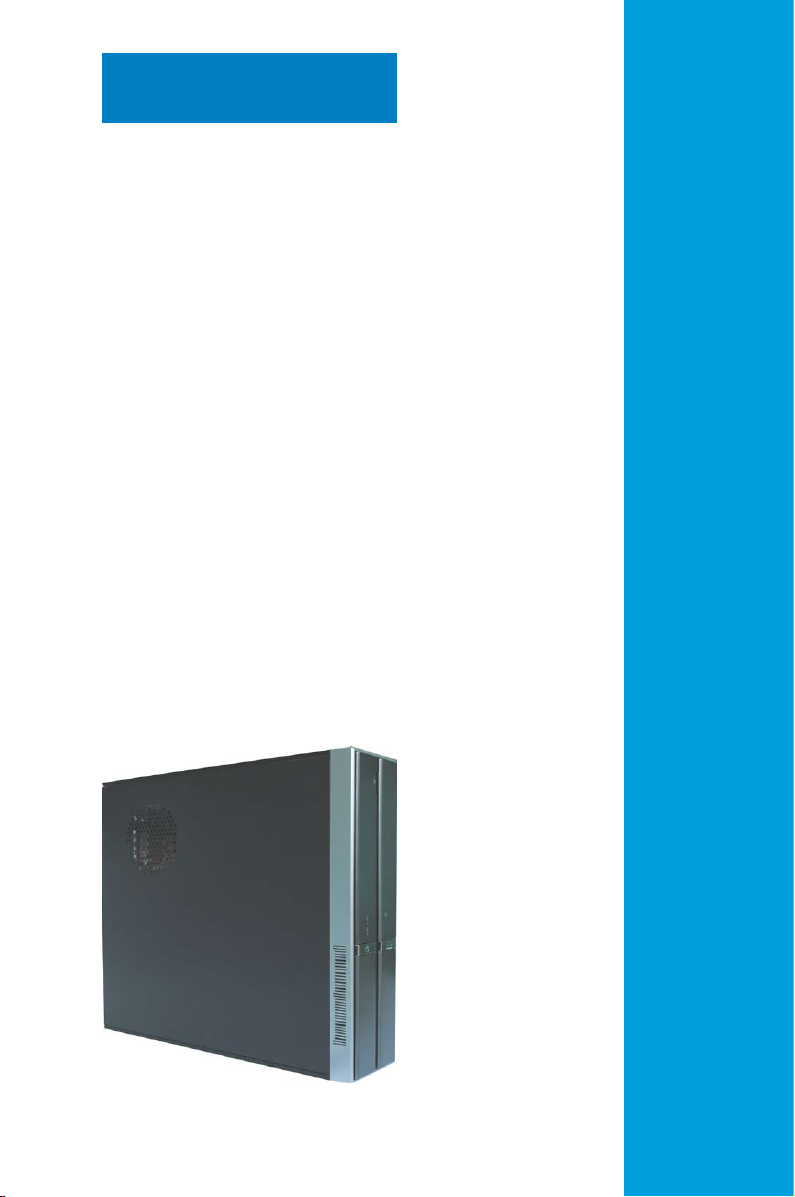
Chapter 1
This chapter gives a general
description of the barebone system.
The chapter lists the system features
including introduction on the front and
rear panel, and internal components.
ASUS P3-P5G31
System introduction
1.1 Welcome!
Thank you for choosing the ASUS P3-P5G31!
The ASUS P3-P5G31 is an all-in-one barebone system with powerful and exible
features.
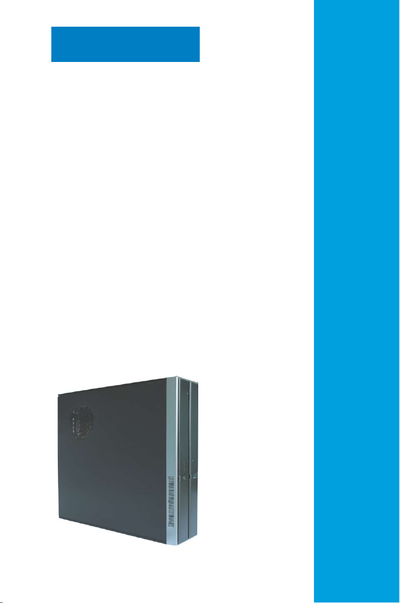
The system comes in a stylish book-size casing, and powered by the ASUS
motherboard that supports the Intel® CoreTM 2 Extreme/Core
TM
2 Duo/ Pentium
®
4/Celeron® D processors in the 775-land package.
With audio capabilities, extensive connectivity, and Fast Ethernet LAN, P3-P5G31
is designed for the sophisticated. The system’s ergonomic design allows vertical or
horizontal placement so you can maximize your desktop space.
With these and many more, the P3-P5G31 denitely delivers the cutting edge
technology for your computing and multimedia needs.
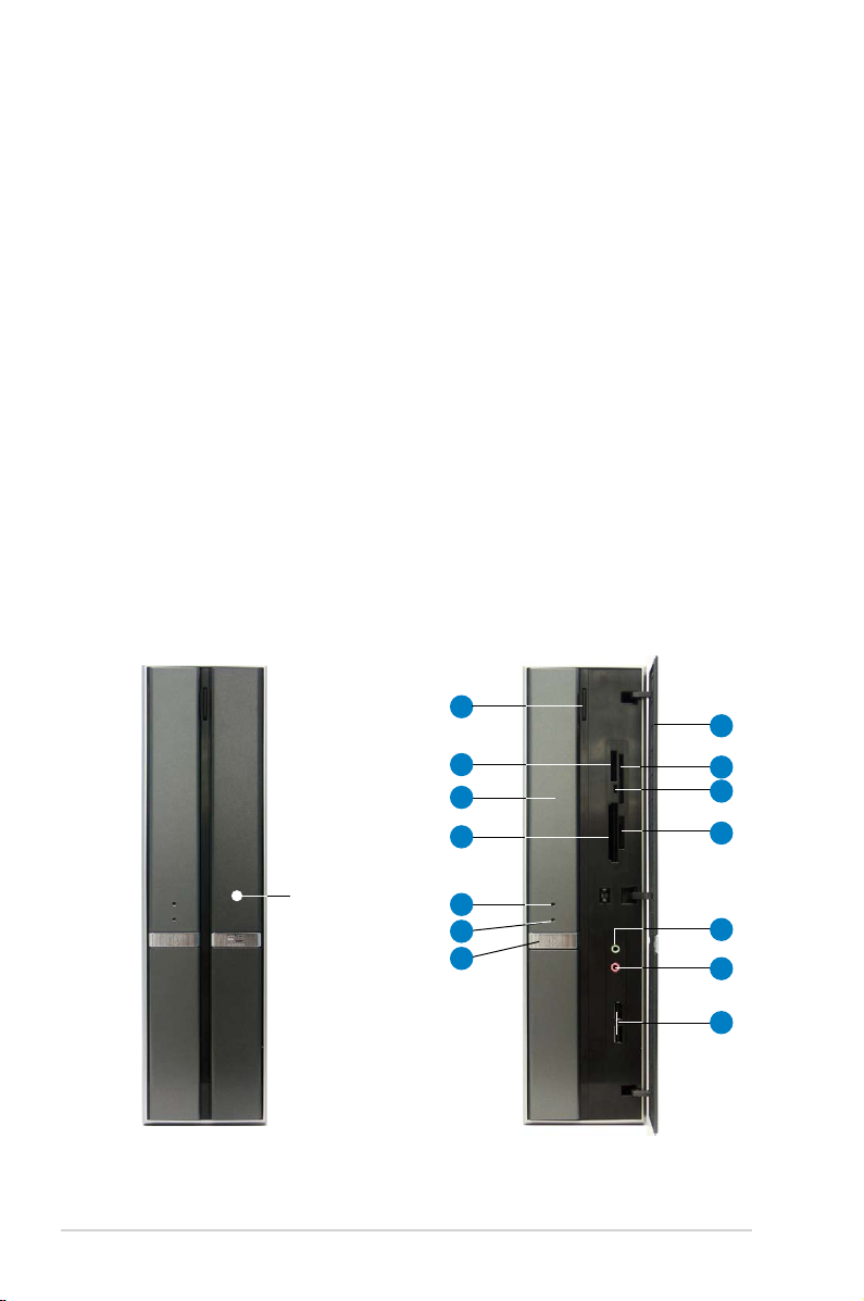
1.2 Front panel
The front panel includes the front panel cover, connectors, power button, and
LEDs.
Close Open
1
2
3
4
Press here to open
the front panel
cover
1-2 Chapter 1: System introduction
5
6
7
8
9
10
11
12
13
14
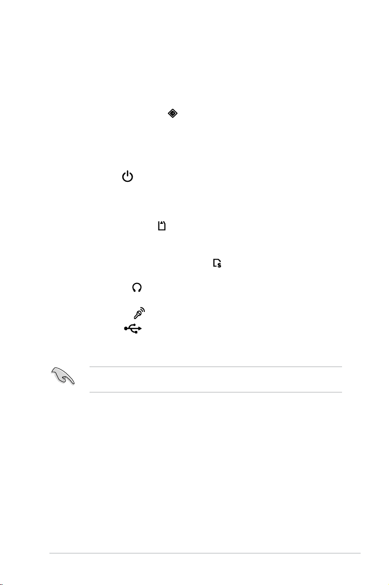
1. Optical drive eject button. Press this button to eject the optical drive tray.
®
2. Memory Stick
/Memory Stick Pro™ card slot*. This slot is for a Memory
Stick®/Memory Stick Pro™ storage card.
3. Optical drive/bay cover.
Covers the optical drive or optical drive bay.
4. CompactFlash® card slot* . This slot is for a CompactFlash® storage
card.
5. Power LED.
6. HDD LED.
This LED lights up to indicate that the system is ON.
This LED lights up when data is being read from or written to the
hard disk drive.
7. Power button . Press this button to turn the system on or off.
8. Front panel cover.
Covers the 6-in-1 card reader and front panel I/O ports.
Press the indicated area to open the front panel cover. Refer to the illustration
in the previous page.
9. SmartMedia
10. Card reader LED.
®
card slot* . This slot is for a SmartMedia® storage card.
This LED lights up when data is being read from or written
to a storage card inserted in any of the card reader slots.
11. Secure Digital™/MultimediaCard slot*
. This slot is for a Secure
Digital™/MultimediaCard storage card.
12. Headphone port
. This port connects a headphone with a stereo mini-
plug.
13. Microphone port
14. USB 2.0 ports
. This Mic (pink) port connects a microphone.
. These Universal Serial Bus 2.0 (USB 2.0) ports are
available for connecting USB 2.0 devices such as a mouse, printer, scanner,
camera, PDA, and others.
* Use and format a storage card according to the documentation that comes
with it.
1-3ASUS P3-P5G31
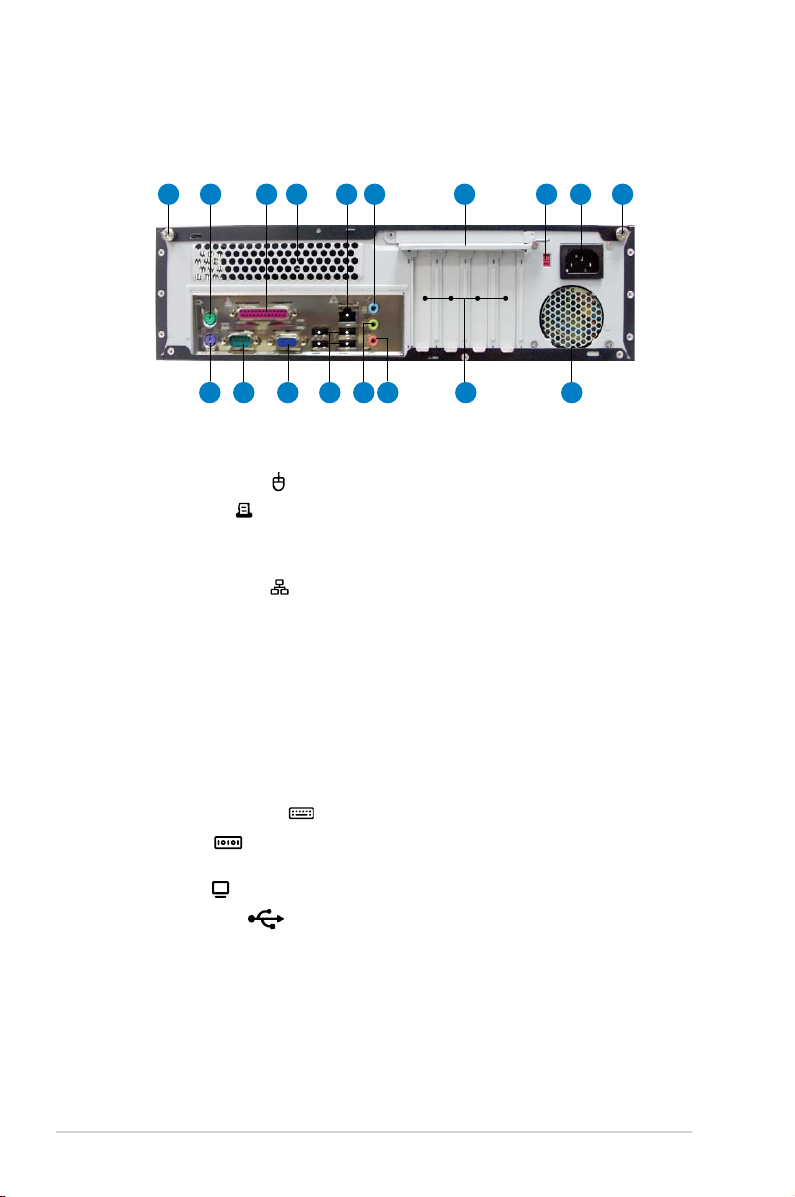
1.3 Rear panel
The system rear panel includes the power connector and several I/O ports that
allow convenient connection of devices.
1
10 11 12 13 14 15 16 17
8 9765432 1
1. Cover screw. Secures the system cover.
2. PS/2 mouse port . This green 6-pin connector is for a PS/2 mouse.
3. Parallel port
. This 25-pin port connects a printer, scanner, or other
devices.
4. Air vent.
5. LAN (RJ-45) port
Provides ventilation for the system.
. This port allows Fast Ethernet connection to a Local
Area Network (LAN) through a network hub.
6. Line In port (light blue).
This port connects a tape, CD, DVD player, or other
audio sources.
7. Metal bracket lock.
8. Voltage selector.
Secures the expansion slot/card metal brackets.
Allows you to adjust the system input voltage according to
the voltage supply in your area. See the section 2.12 Selecting the voltage
before adjusting this switch.
9. Power connector.
Connects the power cable and plug.
10. PS/2 keyboard port . This purple 6-pin connector is for a PS/2 keyboard.
11. COM port
. This port connects a mouse, modem, or other devices that
confoms with serial specication.
12. VGA port
13. USB 2.0 ports
. Connects a VGA monitor.
. These Universal Serial Bus 2.0 (USB 2.0) ports are
available for connecting USB 2.0 devices such as a mouse, printer, scanner,
camera, PDA, and others.
14. Line Out port (lime).
This port connects a headphone or a speaker. In
4-channel, and 6-channel conguration, the function of this port becomes
Front Speaker Out.
1-4 Chapter 1: System introduction
15. Microphone port (pink). This port connects a microphone.
Refer to the audio conguration table below for the function of the audio ports in
2, 4, or 6-channel conguration.
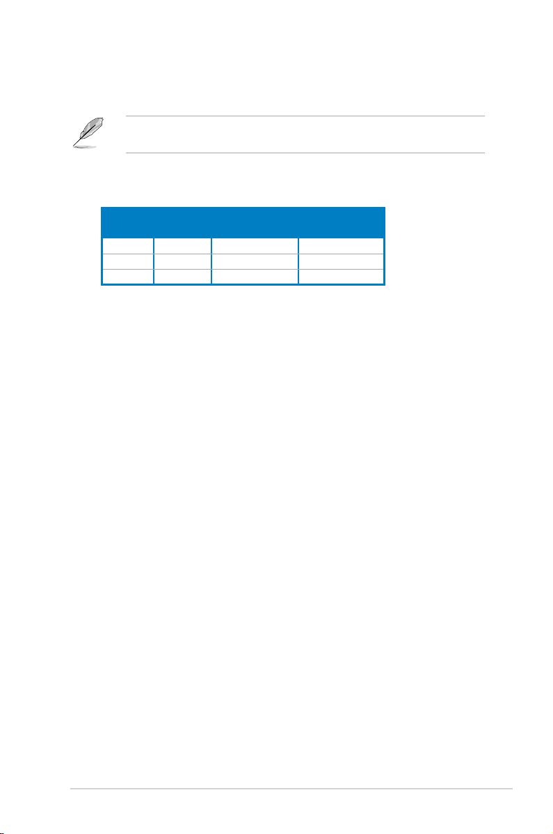
Audio 2, 4, or 6-channel conguration
Port
Light Blue Line In Rear Speaker Out Rear Speaker Out
Lime Line Out Front Speaker Out Front Speaker Out
Pink Mic In Mic In Bass/Center
16. Expansion slots.
Headset
2-channel
4-channel 6-channel
You can insert expansion boards into these slots to add
memory and graphics capabilities to the system.
17. Power fan vent.
The fan vent allows air to be circulated by the power supply
fan.
1-5ASUS P3-P5G31
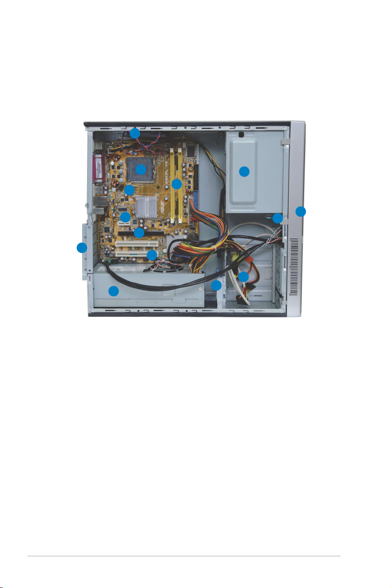
1.4 Internal components
The illustration below is the internal view of the system when you remove the top
cover and the chassis support bracket. The installed components are labeled
for your reference. Proceed to Chapter 2 for instructions on installing additional
system components.
14
12
10
9
8
11
6
7
1. 5.25-inch empty optical drive bay
2. Front panel cover
3. Optical drive lock
4. Hard disk drive bays
5. Hard disk drive lock
6. Power supply unit
7. PCI slots
13
1
3
4
5
8. PCI Express x16 slot
9. PCI Express x1 slot
10. ASUS motherboard
11. Metal bracket lock
12. LGA775 socket
13. DIMM sockets
14. Chassis fan
2
1-6 Chapter 1: System introduction
Chapter 2
This chapter provides step-bystep instructions on how to install
components in the system.
ASUS P3-P5G31
Basic installation
2.1 Preparation
R
Onboard LED
SB_PWR
ON
Standby
Power
OFF
Powered
Off
Before you proceed, make sure that you have all the components you plan to
install in the system.
Basic components to install
1. Central processing unit (CPU)
2. DDR2 Dual Inline Memory Module (DIMM)
3. Expansion card(s)
4. Hard disk drive
5. Optical drive
2.2 Before you proceed
Take note of the following precautions before you install components into the
system.
•
Use a grounded wrist strap or touch a safely grounded object or a metal
object, such as the power supply case, before handling components to
avoid damaging them due to static electricity.
•
Hold components by the edges to avoid touching the ICs on them.
•
Whenever you uninstall any component, place it on a grounded antistatic
pad or in the bag that came with the component.
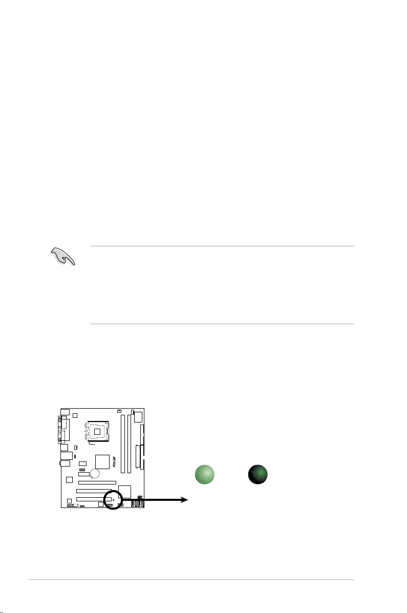
The system motherboard comes with an onboard standby power LED. This LED
lights up to indicate that the system is ON, in sleep mode or in soft-off mode, and
not powered OFF. Unplug the power cable from the power outlet and make sure
that the standby power LED is OFF before installing any system component.
2-2 Chapter 2: Basic installation
2.3 Removing the covers
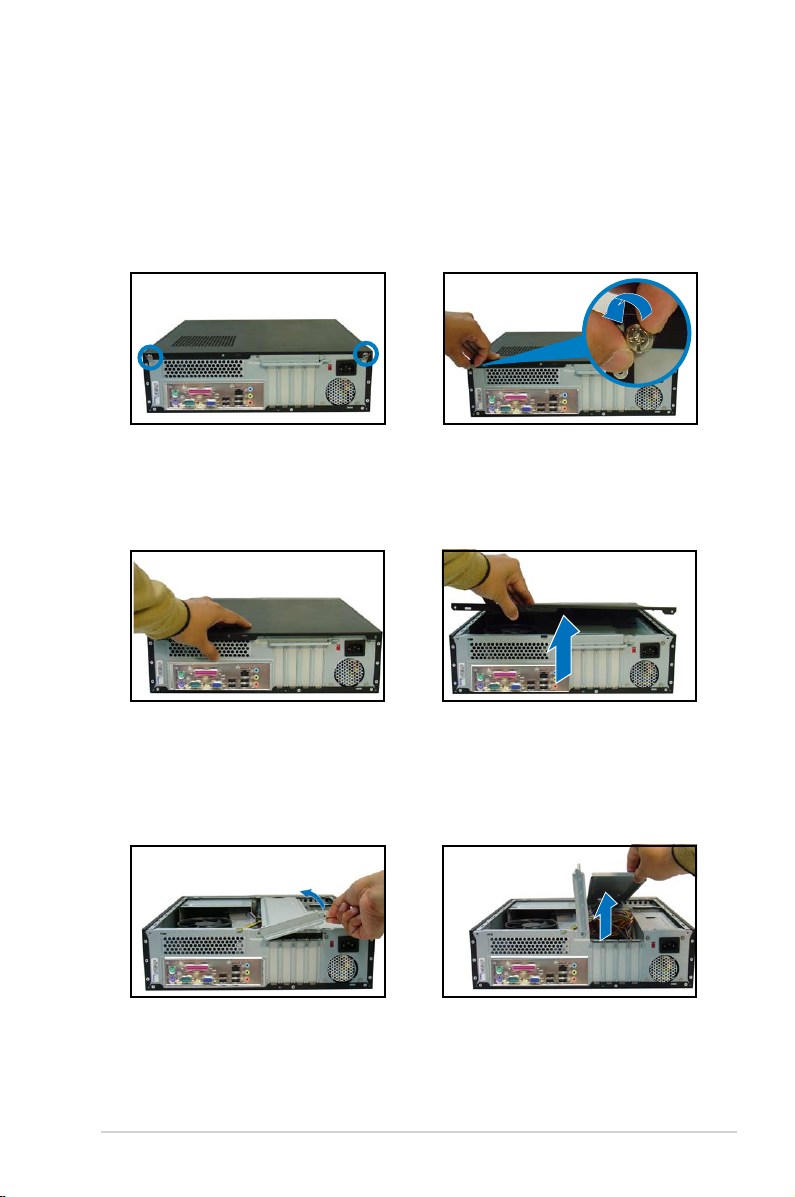
2.3.1 Removing the system cover
To remove the cover and metal chassis support:
1. On the rear panel, locate the two
thumb screws that secure the
cover to the chassis.
3. Slightly pull the cover toward the
rear panel until the cover hooks
disengages from the chassis
holes.
5. Lift the expansion card lock to a
90º-100º angle.
2. Remove the cover screws.
Keep the screws for later use.
4. Lift the system cover, then set
aside.
6. Lift the chassis support
bracket to a 45º angle, then
carefully pull to release. Set
the chassis support bracket
aside.
2-3ASUS P3-P5G31
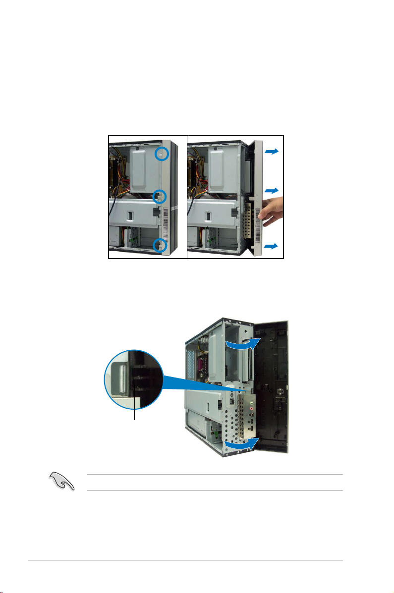
2.3.2 Removing the front panel assembly
To remove the front panel assembly:
1. Place the system vertically.
2. Locate the front panel assembly hooks.
3. Pull the hooks outward to release the front panel assembly.
4. Swing the left edge of the front panel assembly outward.
5. Unhook the hinge-like tabs from the holes on the right side of the chassis to
detach.
Hinge-like tab
Do not use too much force when removing the front panel assembly.
2-4 Chapter 2: Basic installation
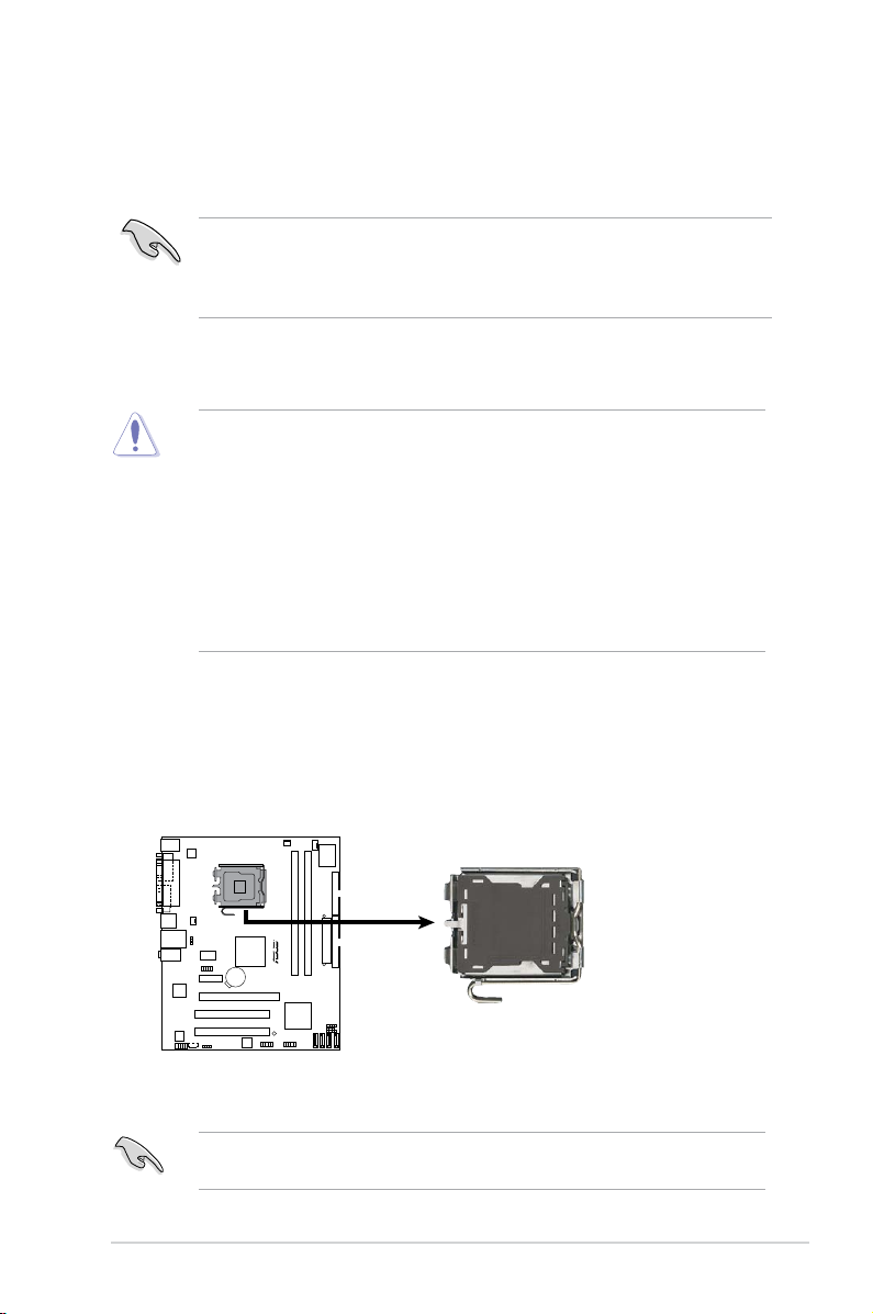
2.4 Installing a CPU
R
CPU Socket 775
The motherboard comes with a surface mount LGA775 socket designed for
the Intel® Core™2 Quad / Core™2 Extreme / Core™2 Duo / Pentium® Extreme /
Pentium® D/ Pentium® 4 processors.
This system is designed for Intel® 65W desktop processors. Other Intel®
processors higher than 65W may not provide optimum performance.
Refer to ASUS CPU support list for more details.
http://support.asus.com/cpusupport/cpusupport.aspx?SLanguage=en-us.
2.4.1 CPU installation
• Your boxed Intel® LGA775 processor package should come with installation
instructions for the CPU, heatsink, and the retention mechanism. If the
instructions in this section do not match the CPU documentation, follow the
latter.
•
Check your motherboard to make sure that the socket contacts are not
bent. Contact your retailer immediately if you see any damage to the socket
contacts/motherboard components. ASUS will shoulder the cost of repair
only if the damage is shipment/transit-related.
• The product warranty does not cover damage to the socket contacts
resulting from incorrect CPU installation or removal.
Installing the CPU
To install a CPU:
1. Locate the CPU socket on the motherboard.
Before installing the CPU, make sure that the socket box is facing towards you
and the load lever is on your left.
2-5ASUS P3-P5G31
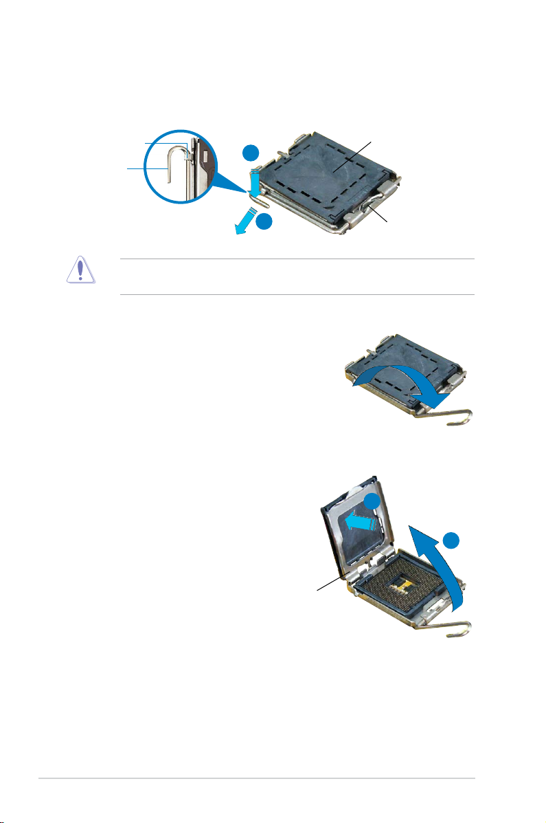
2. Press the load lever with your thumb (A) and move it to the left (B) until it is
released from the retention tab.
Retention tab
Load lever
To prevent damage to the socket pins, do not remove the PnP cap unless you
are installing a CPU.
A
B
3. Lift the load lever in the direction of
the arrow to a 135º angle.
4. Lift the load plate with your thumb
and forenger to a 100º angle (A),
then push the PnP cap from the load
plate window to remove (B).
PnP Cap
This side of the cam box
should face you.
B
A
Load plate
2-6 Chapter 2: Basic installation
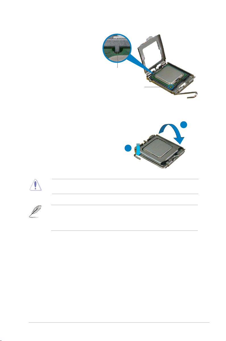
5. Position the CPU over
the socket, making sure
that the gold triangle is
on the bottom-left corner
of the socket. The socket
alignment key should t into
the CPU notch.
Alignment key
Gold triangle mark
6. Close the load plate (A), then push
the load lever (B) until it snaps into
the retention tab.
The CPU ts in only one correct orientation. DO NOT force the CPU into the
socket to prevent bending the connectors on the socket and damaging the CPU!
The motherboard supports Intel® LGA775 processors with the Intel® Enhanced
Memory 64 Technology (EM64T), Enhanced Intel SpeedStep® Technology
(EIST), and Hyper-Threading Technology. Refer to the Appendix for more
information on these CPU features.
A
B
2-7ASUS P3-P5G31
2.4.2 Installing the CPU fan and heatsink assembly
The Intel® LGA775 processor requires a specially designed heatsink and fan
assembly to ensure optimum thermal condition and performance.
• When you buy a boxed Intel® processor, the package includes the CPU fan
and heatsink assembly. If you buy a CPU separately, make sure that you
use only Intel®-certied multi-directional heatsink and fan.
®
• Your Intel
and requires no tool to install.
If you purchased a separate CPU heatsink and fan assembly, make sure that
the Thermal Interface Material is properly applied to the CPU heatsink or CPU
before you install the heatsink and fan assembly.
LGA775 heatsink and fan assembly comes in a push-pin design
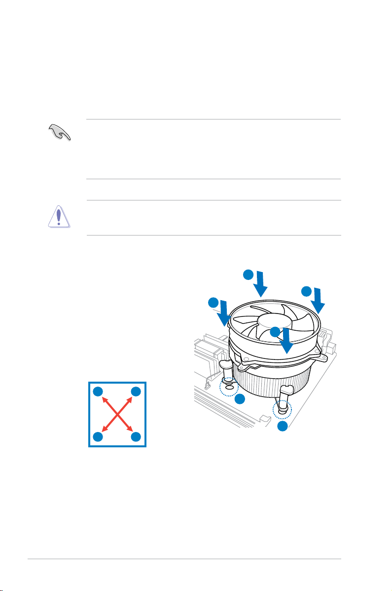
To install the CPU heatsink and fan:
1. Place the heatsink on top of the
installed CPU, making sure that the
four fasteners match the holes on
the motherboard.
2. Push down two fasteners at a time
in a diagonal sequence to secure
the heatsink and fan assembly in
place.
A
B
B
A
A
B
B
A
1
1
2-8 Chapter 2: Basic installation
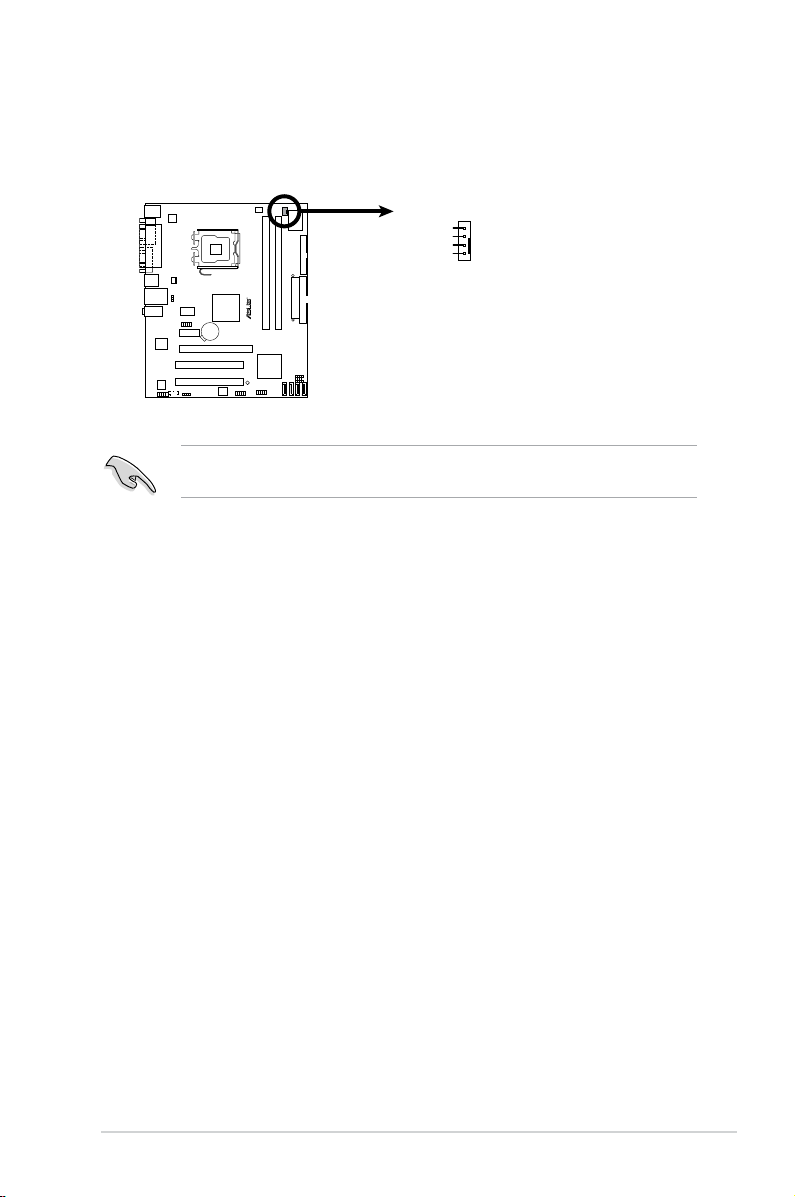
3. When the fan and heatsink assembly is in place, connect the CPU fan cable
R
CPU Fan Connector
GND
CPU FAN PWR
CPU FAN IN
CPU FAN PWM
CPU_FAN
to the connector on the motherboard.
Do not forget to connect the CPU fan connector! Hardware monitoring errors
can occur if you fail to plug this connector.
2-9ASUS P3-P5G31
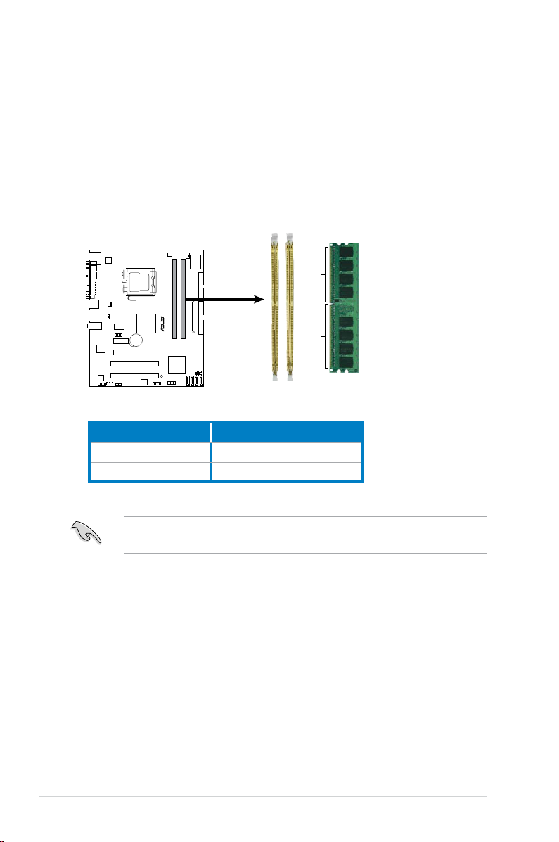
2.5 Installing a DIMM
R
240-pin DDR2 DIMM Sockets
128 Pins
112 Pins
DIMM_B1
DIMM_A1
The motherboard comes with two Double Data Rate 2 (DDR2) Dual Inline Memory
Modules (DIMM) sockets.
A DDR2 module has the same physical dimensions as a DDR DIMM but has a
240-pin footprint compared to the 184-pin DDR DIMM. DDR2 DIMMs are notched
differently to prevent installation on a DDR DIMM socket.
The gure illustrates the location of the DDR2 DIMM sockets:
Channel Sockets
Channel A DIMM_A1
Channel B DIMM_B1
Install a memory module in DIMM_A1 slot to support the Intel® Quiet System
Technology and for optimum performance.
2-10 Chapter 2: Basic installation
2.5.1 Memory congurations
You may install 256 MB, 512 MB, 1 GB and 2 GB unbuffered non-ECC DDR2
DIMMs into the DIMM sockets.
• You may install varying memory sizes in Channel A and Channel B. The
system maps the total size of the lower-sized channel for the dual-channel
conguration. Any excess memory from the higher-sized channel is then
mapped for single-channel operation.
• Always install DIMMs with the same CAS latency. For optimum compatibility,
it is recommended that you obtain memory modules from the same vendor.
• If you are using a Windows 31-bit version operating system (e.g. 32-bit
Windows XP, 32-bit Windows Vista) without the Physical Address Extension
(PAE) support, the system will allocate a certain amount of memory space for
system devices.
• We recommend that you install only a maximum of 3GB system memory
when using a Windows 32-bit version operating system without the PAE.
The excess over 3GB of installed memory will not cause any problem;
however, the system can not use this excess memory space and the
system will display less than the total size of physical memory installed.
• This motherboard does not support memory modules made up of 128 Mb
chips or double sided x16 memory modules.
Notes on memory limitations
• Due to chipset limitation, this motherboard can only support up to
4 GB on the operating systems listed below. You may install a maximum
of 2 GB DIMMs on each slot, but only DDR2-800 and DDR2-667 2 GB
density modules are available for this conguration.
Windows
Windows® 2003 Server
Windows
• Some old-version DDR2-800 DIMMs may not match Intel®
On-Die-Termination (ODT) requirement and will automatically downgrade
to run at DDR-667. If this happens, contact your memory vendor to check
the ODT value.
32-bit 64-bit
®
®
XP
Vista
Windows® XP x64 Edition
Windows® 2003 Server x64 Edition
Windows® Vista x64 Edition
2-11ASUS P3-P5G31
DDR2 Qualied Vendors List
The following tables list the memory modules that have been tested and qualied
for use with this motherboard. Visit the ASUS website (www.asus.com) for the
latest DDR2 DIMM modules for this motherboard.
DDR2 667 Qualified Vendors List
Size Vendor Model Brand Side(s) Part No.
256MB Kingston KVR667D2N5/256 Kingston SS E2508AB-6E-E • •
256MB Kingston KVR667D2N5/256 Kingston SS D3216TLSAKL3U • •
256MB Kingston KVR667D2N5/256 Inneon SS HYB18T256800AF3SW6533154 • •
512MB Kingston KVR667D2N5/512 Kingston SS D6408TE8WL-27 • •
512MB Kingston KVR667D2N5/512 Elpida SS E5108AGBG-6E-E • •
1G Kingston KVR667D2N5/1G Kingston DS D6408TE8WL-3 • •
1G Kingston KVR667D2N5/1G Kingston DS D6408TEBGGL3U • •
1G Kingston KVR667D2N5/1G Elpida DS E5108AGBG-6E-E • •
512MB Samsung KRM378T6553CZ0-CE6 Samsung SS K4T51083QC • •
512MB Samsung KRM378T6453FZ0-CE6 Samsung DS K4T56083QF-ZCE6 • •
512MB Samsung M378T6553CZ3-CE6 Samsung SS K4T51083QC-ZCE6 • •
1G Samsung M378T2953CZ3-CE6 Samsung DS K4T51083QC-ZCE6 • •
1G Samsung KRM378T2953CZ0-CE6 Samsung DS K4T51083QC-ZCE6 • •
256MB Qimonda HYS64T32000HU-3S-A Qimonda SS HYB18T512160AF-3SSSS17310 • •
512MB Qimonda HYS64T32000HU-3S-A Qimonda SS HYB18T5128000AF-3SSSS27416 • •
512MB Qimonda HYS64T64000HU-3S-A Qimonda SS HYB18T512800AF3SFSS05346 • •
1G Qimonda HYS64T128020HU-3S-A Qimonda DS HYB18T512800AF3SSSS28104 • •
512MB Corsair VS512MB667D2 Corsair SS 64M8CFEGPS0900647 • •
512MB Corsair VS512MB667D2 Corsair DS MIII0052532M8CEC • •
1G Corsair VS1GB667D2 Corsair DS MID095D62864M8CEC • •
1G Corsair XMS2-5400 Corsair DS Heat-SinkPackage • •
256MB HY HYMP532U64CP6-Y5AB Hynix SS HY5PS121621CFP-Y5 • •
512MB HY HYMP564U64AP8-Y4AA Hynix SS HY5PS12821AFP-Y4 • •
512MB HY HYMP564U64AP8-Y5AA Hynix SS HY5PS12821AFP-Y5 • •
1G HY HYMP512U64AP8-Y5AB Hynix DS HY5PS12821AFP-Y5 • •
1G HY HYMP512U64CP8-Y5AB Hynix DS HY5PS12521CFP-Y5 • •
512MB Kingmax KLCC28F-A8EB5 Elpida SS E5108AE-6E-E • •
512MB Kingmax KLCC28F-A8KB5 Kingmax SS KKEA88B4LAUG-29DX • •
1G Kingmax KLCD48F-A8KB5 Kingmax DS KKEA88B4LAUG-29DX • •
512MB Apacer 78.91092.420 Elpida SS E5108AE-6E-E • •
512MB Apacer AU512E667C5KBGC Apacer SS AM4B5708MIJS7E0627B • •
512MB Apacer AU512E667C5KBGC Apacer SS AM4B5708GQJS7E06332F • •
1G Apacer AU01GE667C5KBGC Apacer DS AM4B5708GQJS7E0636B • •
1G Apacer 78.01092.420 Elpida DS E5108AE-6E-E • •
1G Apacer AU01GE667C5KBGC Apacer DS AM4B5708MIJS7E0627B • •
512MB ADATA M20EL5G3H3160B1C0Z Elpida SS E5108AE-6E-E • •
512MB ADATA M20AD5G3H3166I1C52 ADATA SS AD29608A8A-3EG20648 • •
512MB ADATA M20AD5G3H3166I1C52 ADATA SS AD29608A8A-3EG20718 • •
1G ADATA M2OAD5G3I4176I1C52 ADATA DS AD29608A8A-3EG20645 • •
512MB ADATA M2GVD5G3H31A4I1C52 ADATA SS AD29608A8A-3EG20615 • •
DIMM support
A* B*
(continued on the next page)
2-12 Chapter 2: Basic installation

DDR2 667 Qualified Vendors List
Size Vendor Model Brand Side(s) Part No.
512MB VDATA M2YVD5G3H31P4I1C52 VDATA SS VD29608A8A-3EG20627 • •
512MB VDATA M2GVD5G3H166I1C52 VDATA SS VD29608A8A-3EG20637 • •
1G VDATA M2GVD5G3I41P6I1C52 VDATA DS VD29608A8A-3EG20627 • •
1G VDATA M2GVD5G3I41C4I1C52 VDATA DS VD29608A8A-3EC20620 • •
1G VDATA M2GVD5G3I4176I1C52 VDATA DS VD29608A8A-3EG20641 • •
512MB PSC AL6E8E63B-6E1K PSC SS A3R12E3GEF637BLC5N • •
1G PSC AL7E8E63B-6E1K PSC DS A3R12E3GEF637BLC5N • •
256MB Nanya NT256T64UH4A1FY-3C Nanya SS NT5TU32M16AG-3C • •
512MB Nanya NT512T64U88A1BY-3C Nanya SS NT5TU64M8AE-3C • •
512MB MDT MDT512MB MDT SS 18D51280D-30648 • •
1G MDT MDT1024MB MDT DS 18D51200D-30646 • •
1G MDT MDT1024MB MDT DS 18D51280D-30646E • •
1G PQI DDR2-667U1G Hynix DS HY5PS12821BFP-E3A • •
512MB AENEON AET660UD00-30DA98Z AENEON SS AET93F30DA0552 • •
512MB AENEON AET660UD00-30DB97X AENEON SS AET93R300B0634 • •
1G AENEON AET760UD00-30DA98Z AENEON DS AET93F30DA8EE47414G0540 • •
512MB AENEON AET660UD00-30DA98Z AENEON SS AET93F300A0606
1G AENEON AET760UD00-30DA98Z AENEON DS AET93F30DA0604 • •
1G AENEON AET760UD00-30DB97X AENEON DS AET93R300B0639 • •
512MB TAKEMS TMS51B264C081-665QI takeMS SS MS18T51280-3 • •
512MB TAKEMS TMS51B264C081-665AP takeMS SS MS18T51280-3S0627D • •
1G TAKEMS TMS1GB264C081-665QI takeMS DS MS18T51280-3 • •
1G TAKEMS TMS1GB264C081-665AE takeMS DS MS18T51280-3SEA07100 • •
1G TAKEMS TMS1GB264C081-665AP takeMS DS MS18T51280-3SP0717A • •
512MB VERITECH GTP512HLTM45EG VERITECH SS VTD264M8PC6G01A164129621 • •
1G VERITECH GTP01GHLTM55EG VERITECH DS VTD264M8PC6G01A164129621 • •
512MB GEIL GX21GB5300DC GEIT SS Heat-SinkPackage • •
512MB TEAM TVDD512M667C5 TEAM SS T2D648MT-6 • •
1G TEAM TVDD1.02M667C4 TEAM DS T2D648PT-6 • •
512MB Century CENTURY512MB Nanya SS NT5TU64M8AE-3C • •
512MB Century CENTURY512MB Hynix SS HY5PS12821AFP-Y5 • •
1G Century CENTURY1G Hynix DS HY5PS12821AFP-Y5 • •
1G Century CENTURY1G Nanya DS NT5TU64M8AE-3C • •
512MB KINGBOX 512MB667MHz KINGBOX SS EPD264082200-4 • •
1G KINGBOX DDRII1G667MHz KINGBOX DS EPD264082200-4 • •
DIMM support
A* B*
Side(s): SS - Single Sided DS - Double Sided
DIMM Support:
A - supports one module inserted into either slot, in a Single-channel memory
conguration.
B - supports on pair of modules inserted into either the yellow slots or the black
slots as one pair of Dual-channel memory conguration.
2-13ASUS P3-P5G31
DDR2 800 Qualified Vendors List
Size Vendor Model Brand Side(s) Part No.
512MB Kingston KVR800D2N5/512 Samsung SS K4T51083QC-ZCE7 • •
512MB Kingston KVR800D2N5/512 Promos SS V59C1512804QBF25S0054707PEBPA • •
1G Kingston KVR800D2N5/1G Samsung DS K4T51083QC-ZCE7 • •
1G Kingston KHX6400D2LL/1G Kingston DS Heat-Sink Package • •
1G Kingston KVR800D2N5/1G Nanya DS NT5TU64M8BE-25C62321800CP • •
1G Kingston KHX6400D2LLK2/1GN Kingston DS Heat-Sink Package • •
2G Kingston KHX6400D2K2/2G Kingston DS Heat-Sink Package • •
512MB Samsung KR M378T6553CZ3-CE7 Samsung SS K4T51083QC-ZCE7 • •
1G Samsung KR M378T2953CZ3-CE7 Samsung DS K4T51083QC-ZCE7 • •
256MB Qimonda HYS64T32001HU-2.5-A Qimonda SS HYB18T256800AF25SSS49313 • •
512MB Qimonda HYS64T64020HU-2.5-A Qimonda DS HYB18T256800AF25SSS25063 • •
1G Corsair CM2X1024-6400 Corsair DS Heat-Sink Package • •
1G Corsair XMS2-6400 Corsair DS Heat-Sink Package • •
1G Corsair XMS2-6400 Corsair DS Heat-Sink Package • •
512MB HY HYMP564U64AP8-S6 AA Hynix SS HY5PS12821AFP-S6 • •
512MB HY HYMP564U64BP8-S5 AB Hynix SS HY5PS12821BFP-S5 • •
512MB HY HYMP564U64CP8-S5 AB Hynix SS HY5PS12821CFP-S5 • •
1G HY HYMP512U64AP8-S6 AA Hynix DS HY5PS12821AFP-S6 • •
1G HY HYMP512U64BP8-S5 AB Hynix DS HY5PS12821BFP-S5 • •
1G HY HYMP512U64CP8-S5 AB Hynix DS HY5PS12821CFPS5 • •
2G Apacer AHU02GE800C5N1C Apacer DS Heat-Sink Package •
512MB ADATA M20AD6G3H3160I1E58 ADATA SS AD29608A8A-25EG80720 • •
512MB VDATA M2GVD6G3H3160I1E53 VDATA SS VD29608A8A-25EG30648 • •
1G VDATA M2GVD6G3I4170I1E53 VDATA DS VD29608A8A-25EG30647 • •
512MB PSC AL6E8E63B-8E1K PSC SS A3R12E3HEF641B9A05 • •
1G PSC AL7E8E63B-8E1K PSC DS A3R12E3HEF641B9A05 • •
512MB AENEON AET660UD00-25DB98X AENEON SS AET93F25DB 0621 • •
1G AENEON AET760UD00-25DB97X AENEON DS AET93R25DB 0640 • •
512MB SIS SLY264M8-JGE-3 SIS SS DDRII6408-8E 7212 • •
1G SIS SLY264M8-JGE-3 SIS DS DDRII6408-8E 7301 • •
512MB TAKEMS TMS51B264C081-805EP takeMS SS MS18T51280-2.5P0710 • •
1G TAKEMS TMS1GB264C081-805EP takeMS DS MS18T51280-2.5P0716 • •
512MB VERITECH GTU512HLTXX4EG Veritech SS VTD264M8PC4G03A169045648 • •
1G VERITECH GTU01GHLTXX4EG Veritech DS VTD264M8PC4G03A169045648 • •
1G UMAX 1GB,DDR2,PC6400 UMAX DS U2S12D30TP-8E • •
DIMM support
A* B*
Side(s): SS - Single Sided DS - Double Sided
DIMM Support:
A - supports one module inserted into either slot, in a Single-channel memory
conguration.
B - supports on pair of modules inserted into either the yellow slots or the black
slots as one pair of Dual-channel memory conguration.
2-14 Chapter 2: Basic installation
 Loading...