

Page 1

®
P3B-1394
IEEE-1394 Motherboard
USER’S MANUAL
Page 2

USER'S NOTICE
No part of this manual, including the products and software described in it, may be reproduced, transmitted, transcribed, stored in a retrieval system, or translated into any language in
any form or by any means, except documentation kept by the purchaser for backup purposes,
without the express written permission of ASUSTeK COMPUTER INC. (“ASUS”).
ASUS PROVIDES THIS MANUAL “AS IS” WITHOUT WARRANTY OF ANY KIND,
EITHER EXPRESS OR IMPLIED, INCLUDING BUT NOT LIMITED T O THE IMPLIED
WARRANTIES OR CONDITIONS OF MERCHANT ABILITY OR FITNESS FOR A PARTICULAR PURPOSE. IN NO EVENT SHALL ASUS, ITS DIRECTORS, OFFICERS,
EMPLOYEES OR AGENTS BE LIABLE FOR ANY INDIRECT, SPECIAL, INCIDENTAL, OR CONSEQUENTIAL DAMAGES (INCLUDING DAMAGES FOR LOSS OF
PROFITS, LOSS OF BUSINESS, LOSS OF USE OR DATA, INTERRUPTION OF BUSINESS AND THE LIKE), EVEN IF ASUS HAS BEEN ADVISED OF THE POSSIBILITY
OF SUCH DAMAGES ARISING FROM ANY DEFECT OR ERROR IN THIS MANUAL
OR PRODUCT.
Product warranty or service will not be extended if: (1) the product is repaired, modified or
altered, unless such repair, modification of alteration is authorized in writing by ASUS; or (2)
the serial number of the product is defaced or missing.
Products and corporate names appearing in this manual may or may not be registered trademarks or copyrights of their respective companies, and are used only for identification or
explanation and to the owners’ benefit, without intent to infringe.
• Intel, LANDesk, and Pentium are registered trademarks of Intel Corporation.
• Celeron is a trademark of Intel Corporation.
• Vortex and Wavetracing are trademarks of Aureal Semiconductor Incorporated.
• IBM and OS/2 are registered trademarks of International Business Machines.
• Symbios is a registered trademark of Symbios Logic Corporation.
• Windows and MS-DOS are registered trademarks of Microsoft Corporation.
• Adobe and Acrobat are registered trademarks of Adobe Systems Incorporated.
The product name and revision number are both printed on the product itself. Manual revi-
sions are released for each product design represented by the digit before and after the period
of the manual revision number. Manual updates are represented by the third digit in the manual
revision number.
For previous or updated manuals, BIOS, drivers, or product release information, contact ASUS
at http://www.asus.com.tw or through any of the means indicated on the following page.
SPECIFICATIONS AND INFORMATION CONTAINED IN THIS MANUAL ARE FURNISHED FOR INFORMATIONAL USE ONLY, AND ARE SUBJECT TO CHANGE AT
ANY TIME WITHOUT NOTICE, AND SHOULD NOT BE CONSTRUED AS A COMMITMENT BY ASUS. ASUS ASSUMES NO RESPONSIBILITY OR LIABILITY FOR
ANY ERRORS OR INACCURACIES THAT MA Y APPEAR IN THIS MANUAL, INCLUDING THE PRODUCTS AND SOFTWARE DESCRIBED IN IT.
Copyright © 1999 ASUSTeK COMPUTER INC. All Rights Reserved.
Product Name: ASUS P3B-1394
Manual Revision: 2.02 E455
Release Date: September 1999
2 ASUS P3B-1394 User’s Manual
Page 3

ASUS CONTACT INFORMATION
ASUSTeK COMPUTER INC. (Asia-Pacific)
Marketing
Address: 150 Li-Te Road, Peitou, Taipei, Taiwan 112
Telephone: +886-2-2894-3447
Fax: +886-2-2894-3449
Email: info@asus.com.tw
Technical Support
MB/Other (tel): English: +886-2-2890-7121
Notebook (tel): English: +886-2-2890-7122
Server (tel): English: +886-2-2890-7123
Fax: +886-2-2895-9254
Email: tsd@asus.com.tw
Newsgroup: news2.asus.com.tw
WWW: www.asus.com.tw
FTP: ftp.asus.com.tw/pub/ASUS
ASUS COMPUTER INTERNATIONAL (America)
Marketing
Address: 6737 Mowry Avenue, Mowry Business Center, Building 2
Newark, CA 94560, USA
Fax: +1-510-608-4555
Email: info-usa@asus.com.tw
Technical Support
Fax: +1-510-608-4555
BBS: +1-510-739-3774
Email: tsd@asus.com
WWW: www.asus.com
FTP: ftp.asus.com/Pub/ASUS
ASUS COMPUTER GmbH (Europe)
Marketing
Address: Harkortstr. 25, 40880 Ratingen, BRD, Germany
Fax: +49-2102-4420-66
Email: sales@asuscom.de
Technical Support
Hotline: MB/Other: +49-2102-9599-0 Notebook: +49-2102-9599-10
Fax: +49-2102-9599-11
Online Support: www.asuscom.de/de/support
WWW: www.asuscom.de
FTP: ftp.asuscom.de/pub/ASUSCOM
ASUS P3B-1394 User’s Manual 3
Page 4

CONTENTS
1. INTRODUCTION .............................................................................. 7
1.1 How This Manual Is Organized .................................................. 7
1.2 Item Checklist ............................................................................. 7
2. FEATURES ......................................................................................... 8
2.1 The ASUS P3B-1394 Motherboard ............................................ 8
2.1.1 Specifications..................................................................... 8
2.1.2 Special Features ............................................................... 10
2.1.3 Performance Features ...................................................... 10
2.1.4 Intelligence....................................................................... 11
2.2 ASUS P3B-1394 Part Locations ............................................... 12
2.3 ASUS P3B-1394 Part Descriptions .......................................... 13
3. HARDWARE SETUP ...................................................................... 14
3.1 Motherboard Layout ................................................................. 14
3.2 Layout Contents ........................................................................ 15
3.3 Hardware Setup Procedure ....................................................... 17
3.4 Motherboard Settings................................................................ 17
3.5 System Memory (DIMM) ......................................................... 20
3.5.1 General DIMM Notes ...................................................... 20
3.5.2 DIMM Installation ........................................................... 21
3.6 Central Processing Unit (CPU) ................................................. 22
3.6.1 Universal Retention Mechanism...................................... 22
3.6.2 Heatsinks.......................................................................... 22
3.6.3 Installing the Processor .................................................... 23
3.6.4 Recommended Heatsinks for Slot 1 Processors .............. 25
3.6.5 Precautions....................................................................... 26
3.7 Expansion Cards ....................................................................... 27
3.7.1 Expansion Card Installation Procedure............................ 27
3.7.2 Assigning IRQs for Expansion Cards .............................. 27
3.7.3 Assigning DMA Channels for ISA Cards ........................ 28
3.7.4 Accelerated Graphics Port (AGP).................................... 28
3.8 External Connectors.................................................................. 29
3.9 Power Connection Procedures .................................................. 39
4. BIOS SETUP.................................................................................... 40
4.1 Managing and Updating Your BIOS ......................................... 40
4.1.1 Upon First Use of the Computer System ......................... 40
4.1.2 Updating BIOS Procedures (only when necessary)......... 41
4 ASUS P3B-1394 User’s Manual
Page 5

CONTENTS
4.2 BIOS Setup ............................................................................... 43
4.3 Standard CMOS Setup.............................................................. 44
4.4 BIOS Features Setup................................................................. 47
4.5 Chipset Features Setup.............................................................. 51
4.6 Power Management Setup ........................................................ 54
4.7 PNP and PCI Setup ................................................................... 57
4.8 Load BIOS Defaults.................................................................. 59
4.9 Load Setup Defaults.................................................................. 59
4.10 Supervisor Password & User Password .................................... 60
4.11 IDE HDD Auto Detection......................................................... 61
4.12 Save & Exit Setup ..................................................................... 62
4.13 Exit Without Saving .................................................................. 62
5. SOFTWARE SETUP....................................................................... 63
5.1 Operating Systems .................................................................... 63
5.2 Starting Windows For the First Time ........................................ 63
5.3 P3B-1394 Support CD .............................................................. 64
5.4 Intel LDCM Administrator Setup ............................................. 66
5.5 Intel LDCM Client Setup.......................................................... 67
5.6 Install 1394 Host Controller Driver .......................................... 69
5.7 Install ASUS PC Probe Vx.xx .................................................. 70
5.8 Install ASUS Update Vx.xx ...................................................... 71
5.9 Install PC-Cillin 98 Vx.xx ........................................................ 72
5.10 Install ADOBE AcroBat Reader Vx.x ...................................... 73
5.11 Uninstalling Programs .............................................................. 75
5.12 Ulead VideoStudio 3.0 SE DV.................................................. 75
6. SOFTWARE REFERENCE ............................................................ 77
6.1 Intel LANDesk Client Manager................................................ 77
6.2 ASUS PC Probe ........................................................................ 83
6.3 Ulead V ideoStudio 3.0 .............................................................. 89
7. APPENDIX........................................................................................ 93
7.1 PCI-L101 Fast Ethernet Card ................................................... 93
7.2 S370 Series CPU Cards ............................................................ 95
7.3 Glossary .................................................................................... 97
ASUS P3B-1394 User’s Manual 5
Page 6

FCC & DOC COMPLIANCE
Federal Communications Commission Statement
This device complies with FCC Rules Part 15. Operation is subject to the following
two conditions:
• This device may not cause harmful interference, and
• This device must accept any interference received, including interference that
may cause undesired operation.
This equipment has been tested and found to comply with the limits for a Class B
digital device, pursuant to Part 15 of the FCC Rules. These limits are designed to
provide reasonable protection against harmful interference in a residential installation. This equipment generates, uses and can radiate radio frequency energy and, if
not installed and used in accordance with manufacturer's instructions, may cause
harmful interference to radio communications. However, there is no guarantee that
interference will not occur in a particular installation. If this equipment does cause
harmful interference to radio or television reception, which can be determined by
turning the equipment off and on, the user is encouraged to try to correct the interference by one or more of the following measures:
• Re-orient or relocate the receiving antenna.
• Increase the separation between the equipment and receiver.
• Connect the equipment to an outlet on a circuit different from that to which
the receiver is connected.
• Consult the dealer or an experienced radio/TV technician for help.
WARNING! Any changes or modifications to this product not expressly ap-
proved by the manufacturer could void any assurances of safety or performance
and could result in violation of Part 15 of the FCC Rules.
Canadian Department of Communications Statement
This digital apparatus does not exceed the Class B limits for radio noise emissions
from digital apparatus set out in the Radio Interference Regulations of the Canadian Department of Communications.
This Class B digital apparatus complies with Canadian ICES-003.
Cet appareil numérique de la classe B est conforme à la norme NMB-003 du Canada.
6 ASUS P3B-1394 User’s Manual
Page 7

1. INTRODUCTION
1.1 How This Manual Is Organized
This manual is divided into the following sections:
1. Introduction Manual information and checklist
2. Features Information and specifications concerning this product
3. Hardware Setup Instructions on setting up the motherboard and jumpers
4. BIOS Setup Instructions on setting up the BIOS software
5. Software Setup Instructions on setting up the included support software
6. Software Reference Reference material for the included support software
7. Appendix Optional items and general reference
1.2 Item Checklist
Please check that your package is complete. If you discover damaged or missing
items, please contact your retailer.
(1) ASUS Motherboard
Manual / Checklist
1. INTRODUCTION
(1) Universal Retention Mechanism for SECC2/SECC/SEPP processors
(1) Ribbon cable for master and slave IDE drives
(1) Ribbon cable for (1) 5.25” and (2) 3.5” floppy disk drives
(1) Bag of spare jumper caps
(1) ASUS Support CD with drivers and utilities
(1) Ulead VideoStudio™ 3.0 CD
(1) This Motherboard User’s Manual
IEEE-1394+COM2 serial cable connector set, which includes the following:
(1) 1394 CON board
(2) 8-to-6 pin cables
(1) Serial COM2 cable
(1) Metal bracket
ASUS IrDA-compliant infrared module (optional)
ASUS S370 Series CPU cards (optional)
ASUS PCI-L101 Wake-On-LAN 10/100 Ethernet Card (optional)
ASUS P3B-1394 User’s Manual 7
Page 8

2.1 The ASUS P3B-1394 Motherboard
The ASUS P3B-1394 is carefully designed for the demanding PC user who wants
advanced features processed by the fastest CPU.
2.1.1 Specifications
• Multi-Speed: Supports Intel Pentium® III (450MHz and faster), Pentium® II
2. FEATURES
Specifications
• 1394-1995 and 1394.A Ready: Integrated TI
• Intel AGPset: Features Intel’s 440BX AGPset with I/O subsystems and front-side
2. FEATURES
(233MHz to 450MHz), and CeleronTM (266MHz and faster) processors.
®
400Mbps capable link-layer controller and 400Mbps physical layer controller provide a fast, scalable, easy-touse digital interface for throughput intensive consumer electronics devices such
as, DV camcorders, digital cameras, scanners, and printers. IEEE-1394 supports
traditional asynchronous data transfer as well as isochronous (real-time) data
transfer.
bus (FSB) platform, which boosts the traditional 66MHz external bus speed to 100MHz.
• Multi-Cache: Supports processors with 512, 256, 128, or 0KB Pipelined Burst
Level 2 cache.
• Anti-Boot Virus BIOS: Features a programmable BIOS, offering enhanced
Advanced Configuration Power Interface (ACPI) support for Windows 98 com-
patibility , built-in firmware-based virus protection through T rend ChipA way V irus
codes, and autodetection of most devices for virtually automatic setup.
• PC100 Memory Support: Equipped with two DIMM sockets to support Intel
PC100-compliant SDRAMs (8, 16, 32, 64, 128, or 256MB) up to 512MB. These
new SDRAMs are necessary to meet the critical enhanced 100MHz bus speed
requirement.
• PCI Audio with AC’97 Codec (optional): Features Aureal’s Vortex 2 positional 3D audio chip with A3D 2.0 hardware support. A3D 2.0 provides many
advanced 3D audio features, including Aureal W avetracing
waves in real-time to simulate the acoustic characteristics of the environment
for true 3D audio.
• Peripheral Wake Up: Supports modem wake up and LAN card wake up func-
tions from sleep or soft-off mode.
TM
, which traces sound
• PC Health Monitoring: Provides an easier way to examine and manage system
status information, such as CPU and system voltages, temperatures, and fan
status through the onboard hardware ASIC and the bundled LDCM by Intel or
PC Probe from ASUS.
8
ASUS P3B-1394 User’s Manual
Page 9

2. FEATURES
• AGP Slot: Supports an Accelerated Graphics Port card for high performance,
component level interconnect targeted at 3D graphical display applications using a 1X or 2X mode bus.
• Legacy Free: Provides three 32-bit PCI (rev 2.2) expansion slots with no ISA,
eliminating bottlenecks, and system memory management issues. PCI supports
up to 133MB/s maximum throughput.
• Multi-I/O: Provides two high-speed UART compatible serial ports and one paral-
lel port with EPP and ECP capabilities.
• UltraDMA/33 Bus Master IDE: Comes with an onboard PCI Bus Master IDE con-
troller with two connectors that support four IDE devices in two channels. Supports
UltraDMA/33, PIO Modes 3 and 4, and Bus Master IDE DMA Mode 2, as well as
Enhanced IDE devices, such as Tape Backup, CD-ROM, CD-R/RW, and LS-120
drives.
Specifications
2. FEATURES
• Universal Retention Mechanism: Supports a Pentium
aged in a Single Edge Contact Cartridge (SECC2/SECC) or a Celeron
®
III / II processor pack-
TM
proces-
sor packaged in a Single Edge Processor Package (SEPP).
• Wake-On-LAN Connector: Supports Wake-On-LAN activity through an op-
tional ASUS PCI-L101 10/100 Fast Ethernet PCI card (see 7.1 PCI-L101 LAN
Card) or a similar ethernet card.
ASUS P3B-1394 User’s Manual 9
Page 10

2. FEATURES
2.1.2 Special Features
• ACPI Ready: Advanced Configuration Power Interface (ACPI) provides more
Energy Saving Features for operating systems that support OS Direct Power
Management (OSPM) functionality . W ith these features implemented in the OS,
PCs can be ready around the clock, yet satisfy all the energy saving standards.
To fully utilize the benefits of ACPI, an ACPI-supported OS such as Windows
98 must be used.
2. FEATURES
Specifications
• Suspend and Go: Suspend-to-RAM provides maximum power savings as an
• Desktop Management Interface (DMI): Supports DMI through BIOS, which
• Easy Installation: Incorporates BIOS that supports autodetection of hard disk
• PC’98 Compliant: Both the BIOS and hardware levels of ASUS smart series
• Symbios SCSI BIOS: Supports optional ASUS SCSI controller cards through
alternative to leaving the computer ON and QuickStart
asleep waiting for system bootup (Suspend-to-RAM supported OS required).
allows hardware to communicate within a standard protocol creating a higher
level of compatibility. (Requires DMI-enabled components.)
drives, PS/2 mouse, and Plug and Play devices to make the setup of hard disk
drives, expansion cards, and other devices virtually automatic.
motherboards meet PC’98 compliancy. The new PC’98 requirements for systems and components are based on the following high-level goals: Support for
Plug and Play compatibility and power management for configuring and managing all system components, and 32-bit device drivers and installation procedures for Windows95/98/NT .
the onboard SYMBIOS firmware.
TM
so that you do not fall
2.1.3 Performance Features
• 1394 for High Speed Bi-Directional Data T ransfer (100/200/400Mbps): Fast-
est interface for existing and future consumer electronics devices.
• Concurrent PCI: Concurrent PCI allows multiple PCI transfers from PCI mas-
ter busses to the memory and processor.
• Double the IDE Transfer Speed: ASUS smart series motherboards with Intel
chipsets improves IDE transfer rate using Bus Master UltraDMA/33 IDE which
can handle data transfer up to 33MB/s.
• SDRAM Optimized Performance: Supports the new generation memory - Syn-
chronous Dynamic Random Access Memory (SDRAM) which increases the data
transfer rate to 800MB/s max using PC100-compliant SDRAM.
10
ASUS P3B-1394 User’s Manual
Page 11

2. FEATURES
2.1.4 Intelligence
• Dual Function Power Button: Pushing the power button for less than 4 sec-
onds when the system is in the working state places the system into one of two
states: sleep mode or soft-off mode, depending on the BIOS or OS setting (see
PWR Button < 4 Secs in 4.6 Power Management Setup). When the power
button is pressed for more than 4 seconds, the system enters the soft-off mode
regardless of the BIOS setting.
• Fan Status Monitoring and Alarm: To prevent system overheat and system
damage, the CPU, power supply, and system fans can be monitored for RPM
and failure. All fans are set for its normal RPM range and alarm thresholds.
• Message LED (requires ACPI OS support): Turbo LEDs now act as informa-
tion providers. Through the way a particular LED illuminates, the user can determine the stage the computer is in. A simple glimpse provides useful information to the user.
• Remote Ring On (requires modem): This allows a computer with this mother-
board to be turned on remotely through an internal or external modem. With this
feature, users can access their computers from anywhere in the world!
Specifications
2. FEATURES
• System Resources Alert: Today’s operating systems such as Windows 95/98/
NT and OS/2, require much more memory and hard drive space to present enormous user interfaces and run large applications. The system resource monitor
will warn the user before the system resources are used up to prevent possible
application crashes. Suggestions will give the user information on managing
their limited resources more efficiently.
• Temperature Monitoring and Alert: CPU temperature is monitored by the
ASUS ASIC through the CPU’s internal thermal diode (on Pentium III, Deschutes
Pentium II, and PPGA370 Celeron in conjunction with the ASUS S370-D or
S370-L CPU card) to prevent system overheat and system damage.
• Voltage Monitoring and Alert: System voltage levels are monitored to ensure
stable voltage to critical motherboard components. Voltage specifications are
more critical for future processors, so monitoring is necessary to ensure proper
system configuration and management.
ASUS P3B-1394 User’s Manual 11
Page 12
2. FEATURES
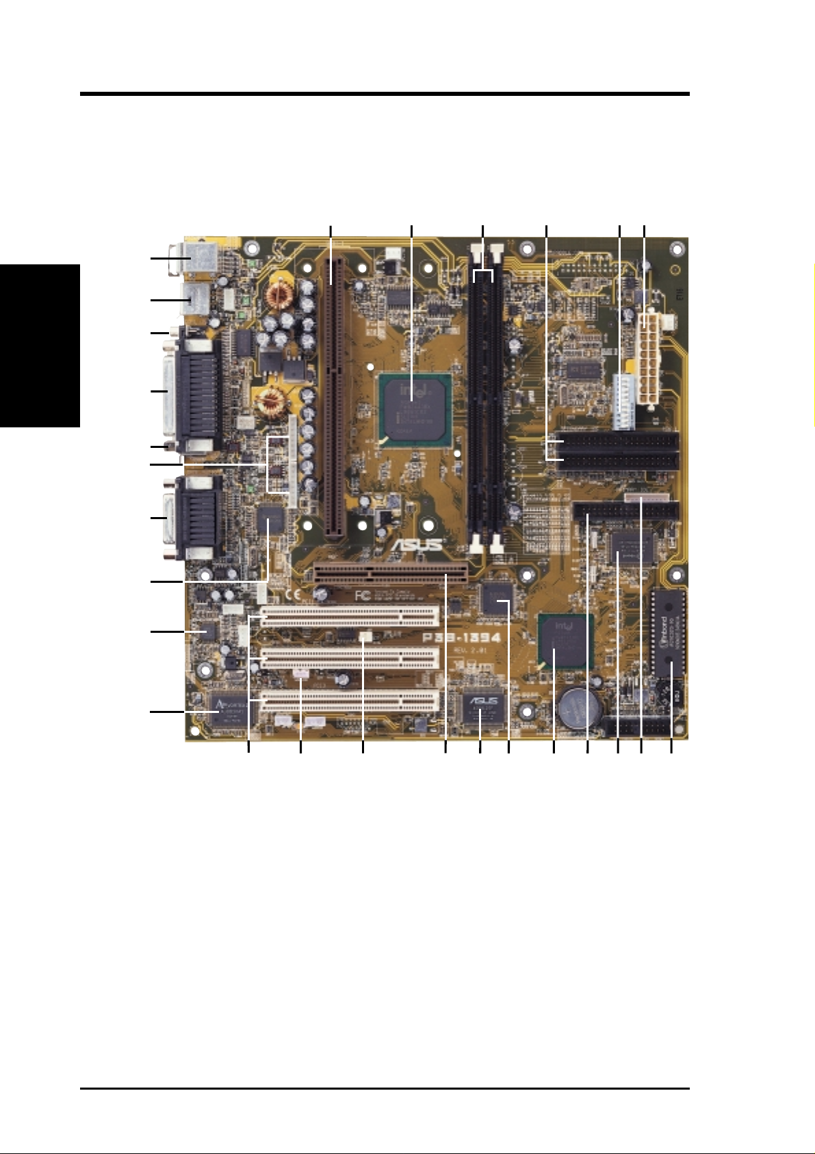
2.2 ASUS P3B-1394 Part Locations
2. FEATURES
Specifications
27
26
25
24
23
22
21
20
1
2
3
4
5
6
19
18
17
16
14
13
1215
11
10
9
8
7
12
ASUS P3B-1394 User’s Manual
Page 13

2. FEATURES
2.3 ASUS P3B-1394 Part Descriptions
1 SEC CPU Socket
2 Intel 440BX AGPset
3 2 DIMM Sockets
4 Primary, Secondary IDE Connectors
5 Function DIP Switches
6 ATX Power Connector
7 Programmable Flash EEPROM
8 Serial COM2 Header
9 Multi I/O Chip
10 Floppy Disk Drive Connector
11 Intel PIIX4E PCIset
2. FEATURES
Motherboard Parts
12 TI 1394 Link Layer Chip
13 ASUS ASIC with hardware monitor
14 Accelerated Graphics Port
15 Wake-On-Ring Connector
16 Wake-On-LAN Connector
17 3 PCI Slots
18 Aureal 3D PCI Audio (optional)
19 AC’97 V2.1 Audio CODEC (for audio model only)
20 TI 1394 Physical Layer Chip
21 T: Joystick/MIDI Connector
B: Line Out, Line In, Microphone In Connectors
(for audio model only)
22 IEEE-1394 Headers (channels 2 & 3)
23 IEEE-1394 Connector (channel 1)
24 Parallel Port Connector
25 Serial Port Connector
26 2 USB Connectors
27 T: PS/2 Mouse Connector
B: PS/2 Keyboard Connector
ASUS P3B-1394 User’s Manual 13
Page 14
3. HARDWARE SETUP
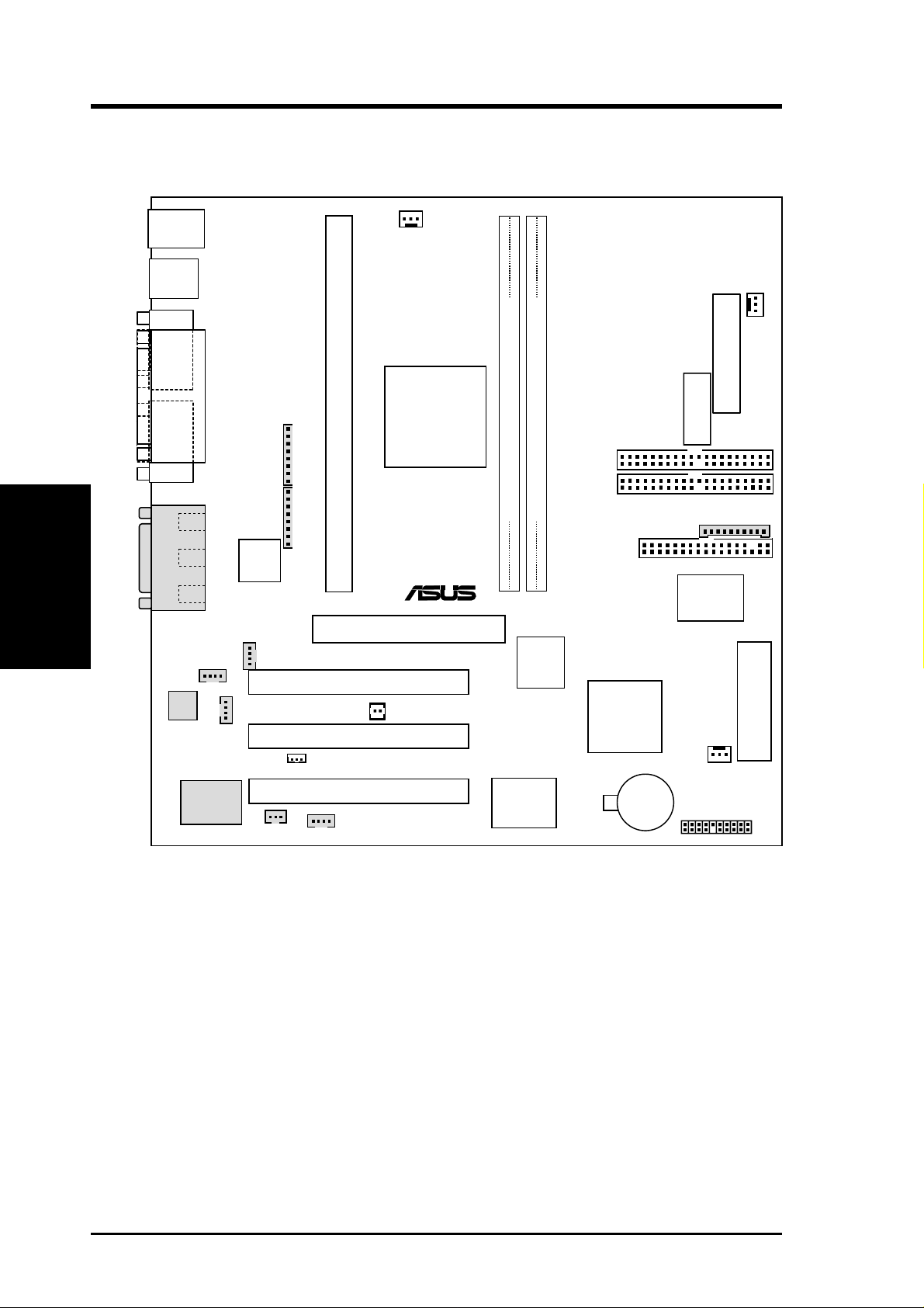
3.1 Motherboard Layout
PS2
KBMS
USB
T: Port1
B: Port2
COM1
PRINTER
PARALLEL PORT
1394_
CON
Motherboard Layout
3. H/W SETUP
GAME_AUDIO
Audio
Codec
Line
Out
Line
In
Mic
In
MODEM
Audio
Chipset
1394HEAD2
1394HEAD3
1394
Physical
Layer
Chip
CD_IN
AUX_CON
SPDIFOUT
CPU_FAN
Intel
Slot 1
440BX
AGPset
Accelerated Graphics Port
PCI Slot 1 (PCI1)
PCI Slot 2 (PCI2)
WOL_CON
PCI Slot 3 (PCI3)
VIDEO
(AGP)
WOR
Row
0
®
P3B-1394
ASUS
ASIC
with Hardware
Monitor
3
2
1
PWR_FAN
ATXPWR
ATX Power Connector
(DIP_SW)
DIP Switches
SECONDARY
DIMM Socket 1 (64/72-bit, 168-pin module)
DIMM Socket 2 (64/72-bit, 168-pin module)
IDE
PRIMARY
IDE
COM2
FLOPPY DISK DRIVE CONN.
Multi
I/O
1394
Link
Layer
Chip
Intel
PIIX4E
PCIset
CHA_FAN
CR2032 3V
Lithium Cell
CMOS Power
PANEL
2Mbit Flash EEPROM
(Programmable BIOS)
(Grayed items are optional at the time of purchase.)
14
ASUS P3B-1394 User’s Manual
Page 15

3. HARDWARE SETUP
3.2 Layout Contents
Motherboard Settings
1) DIP_SW 6–10 p. 18 CPU External Frequency Selection
2) DIP_SW 2–5 p. 19 CPU Core:BUS Frequency Multiple Selection
Expansion Slots/Sockets
1) System Memory p. 20 System Memory Support
2) DIMM1, DIMM2 p. 22 DIMM Memory Module Support
3) SLOT-1 p. 23 CPU Support
4) PCI1, PCI2, PCI3 p. 27 32-bit PCI Bus Expansion Slots
5) AGP p. 28 Accelerated Graphics Port
Connectors
1) PS2KBMS p. 29 PS/2 Mouse Port Connector (6 pin-female)
2) PS2KBMS p. 29 PS/2 Keyboard Port Connector (6-pin female)
3) USB p. 30 Universal Serial Bus Connectors 1 & 2 (Two 4-pin female)
4) PRINTER p. 30 Parallel Port Connector (25-pin female)
5) COM1 p. 30 Serial Port Connector (9-pin male)
6) 1394_CON p. 31 1394 Connector (6-pin male)
7) GAME_AUDIO p. 31 Joystick/MIDI Connector (15-pin female) (optional)
8) GAME_AUDIO p. 31 Audio Port Connectors (Three 1/8” female) (optional)
9) PRIMARY IDE p. 32 Primary/Secondary IDE Connectors (Two 40-1 pins)
SECONDARY IDE
10) FLOPPY p. 32 Floppy Drive Port Connector (34 pins)
11) CHA_, PWR_, CPU_F AN p. 33 Chassis, Power Supply, CPU Fan Connectors (3 pins)
12) WOL_CON p. 34 Wake-On-LAN Connector (3 pins)
13) WOR p. 34 Wake-On-Ring Connector (2 pins)
14) 1394HEAD2/3 p. 35 IEEE-1394 Headers (Two 8-pin male) (optional)
15) MODEM, AUX_CON, p. 35 Internal Audio Connectors (Four 4 pins)
CD_IN, VIDEO
16) MLED (PANEL) p. 36 System Message LED (2 pins)
17)
KEYLOCK (
18) SMI (PANEL) p. 36 System Management Interrupt Lead (2 pins)
19) SPEAKER (PANEL) p. 36 System Warning Speaker Connector (4 pins)
20) PWR (PANEL) p. 36 ATX / Soft-Off Switch Lead (2 pins)
PANEL
)
p. 36 Keyboard Lock Switch Lead (2 pins)
3. H/W SETUP
Layout Contents
21) IDELED (PANEL) p. 36 IDE Device Activity LED (2 pins)
22)
PLED (
23) RESET (PANEL) p. 36 Reset Switch Lead (2 pins)
24) ATXPWR p. 37 ATX Power Supply Connector (20 pins)
25) COM2 p. 38 Serial Port Header (10 pins)
26) SPDIFOUT p. 38 Digital Audio Interface (3 pins)
PANEL
)
p. 36 System Power LED Lead (3 pins)
ASUS P3B-1394 User’s Manual 15
Page 16

(This page was intentionally left blank.)
3. H/W SETUP
3. HARDWARE SETUP
16
ASUS P3B-1394 User’s Manual
Page 17
3. HARDWARE SETUP
3.3 Hardware Setup Procedure
Before using your computer, you must complete the following steps:
1. Check Motherboard Settings
2. Install Memory Modules
3. Install the Central Processing Unit (CPU)
4. Install Expansion Cards
5. Connect Ribbon Cables, Panel Wires, and Power Supply
6. Setup the BIOS Software
3.4 Motherboard Settings
This section explains in detail how to change your motherboard’s function settings
through the use of switches and/or jumpers.
WARNING! Computer motherboards and expansion cards contain very delicate
Integrated Circuit (IC) chips. T o protect them against damage from static electricity, you should follow some precautions whenever you work on your computer.
1. Unplug your computer when working on the inside.
2. Use a grounded wrist strap before handling computer components. If you do
not have one, touch both of your hands to a safely grounded object or to a
metal object, such as the power supply case.
3. Hold components by the edges and try not to touch the IC chips, leads or
connectors, or other components.
4. Place components on a grounded antistatic pad or on the bag that came with
the component whenever the components are separated from the system.
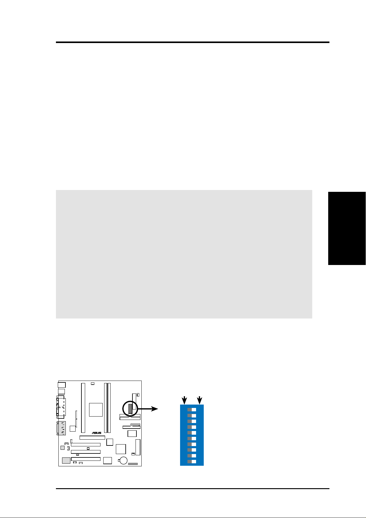
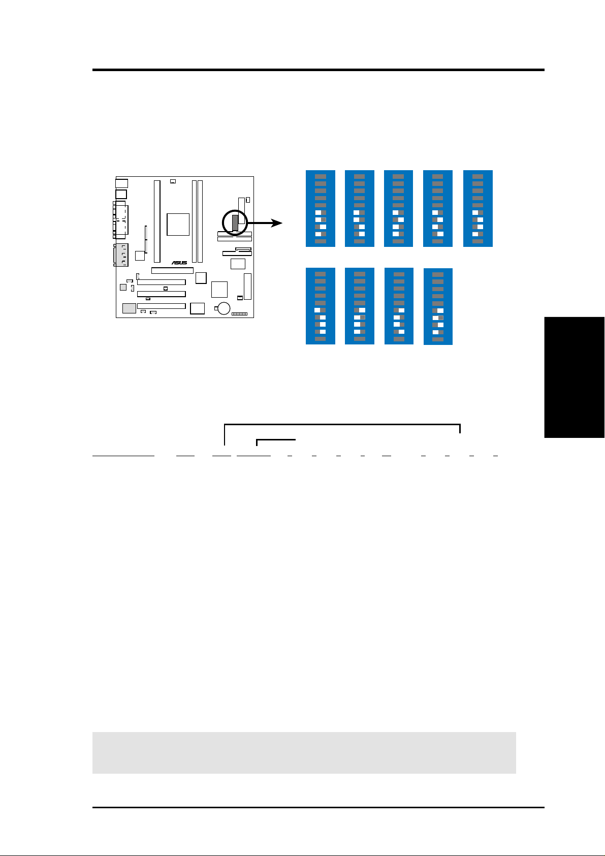
Motherboard Features Settings (DIP Switches - DIP_SW)
The motherboard’s onboard functions are adjusted through the DIP switches. The
white block represents the switch’s position. The example below shows all the
switches in the OFF position.
DIP_SW
®
P3B-1394
ON
OFFON
10. Frequency Selection
9.
Frequency Selection
8.
Frequency Selection
Frequency Selection
7.
6. Frequency Selection
4. Frequency Multiple
3. Frequency Multiple
2. Frequency Multiple
1. Clear CMOS
12345678910
3. H/W SETUP
Motherboard Settings
P3B-1394 DIP Switches
ASUS P3B-1394 User’s Manual 17
Page 18
3. HARDWARE SETUP
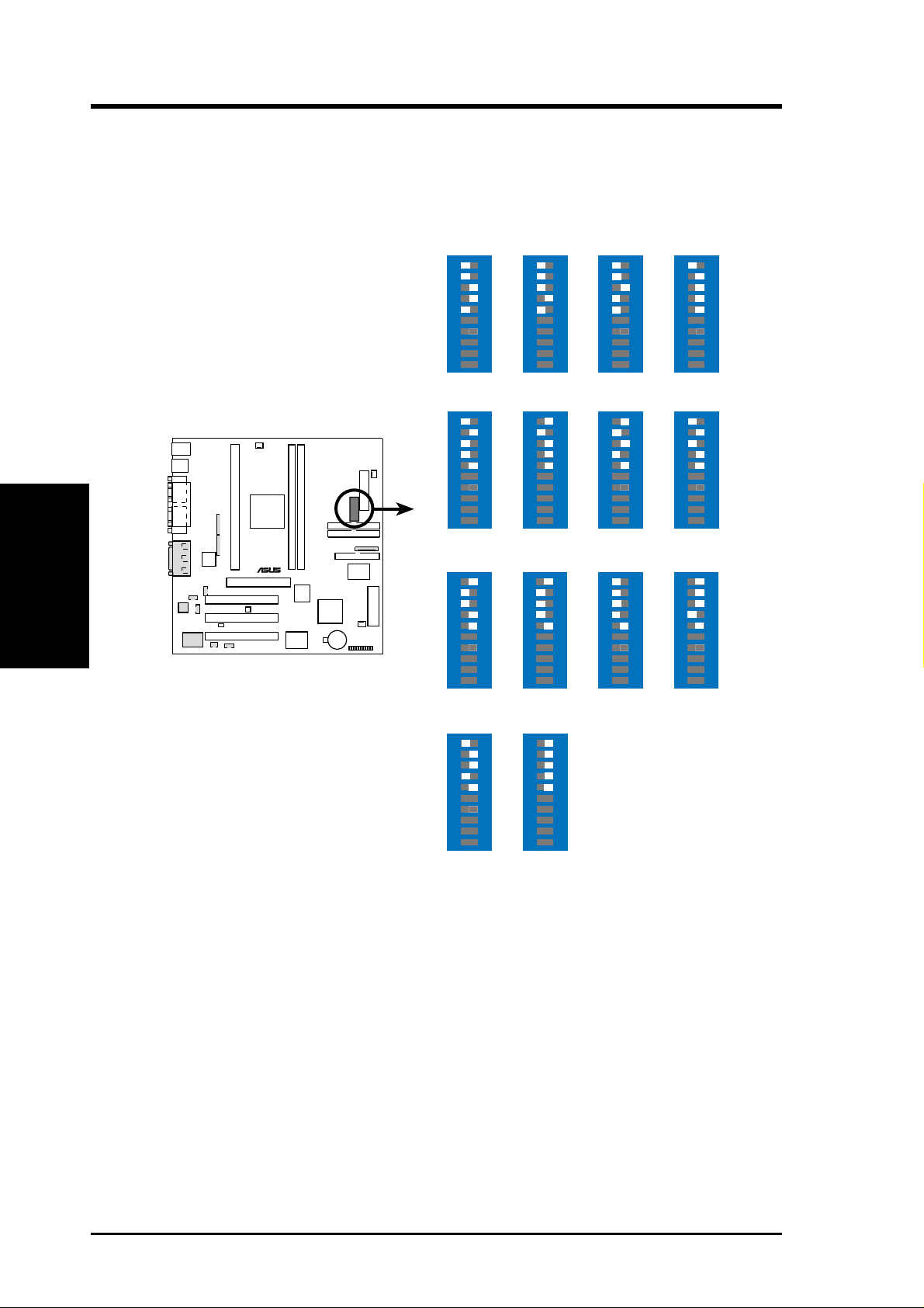
1) CPU External Frequency Selection (DIP_SW Switches 6-10)
This option tells the clock generator what frequency to send to the CPU, DRAM, and
the PCI bus. This allows the selection of the CPU’s External frequency (or BUS Clock).
The BUS Clock multiplied by the Frequency Multiple equals the CPU’s Internal fre-
quency (the advertised CPU speed).
Motherboard Settings
3. H/W SETUP
P3B-1394
CPU External
Frequency Settings
®
P3B-1394
CPU
PCI
CPU
PCI
CPU
PCI
ON
66.0MHz
33.4MHz
ON
103.0MHz
34.3MHz
ON
115.0MHz
38.3MHz
12345678910
12345678910
12345678910
ON
75.0MHz
37.5MHz
ON
105MHz
35MHz
ON
120.0MHz
40.0MHz
12345678910
12345678910
12345678910
ON
83.0MHz
41.6MHz
ON
110.0MHz
36.7MHz
ON
124.0MHz
41.3MHz
12345678910
12345678910
12345678910
ON
100.0MHz
33.4MHz
ON
112.0MHz
37.3MHz
ON
124.0MHz
31.0MHz
12345678910
12345678910
12345678910
CPU
PCI
ON
133.0MHz
44.3MHz
12345678910
ON
133.0MHz
33.3MHz
12345678910
NOTE: Overclocking your processor is not recommended. It may result in a slower
speed. Voltage Regulator Output Selection (VID) is not needed for the Pentium III /
II / Celeron processor because it sends VID signals directly to the onboard power
controller.
18
ASUS P3B-1394 User’s Manual
Page 19
3. HARDWARE SETUP
2) CPU Core:BUS Frequency Multiple (DIP_SW Switches 1-4)
This option sets the frequency multiple between the Internal frequency of the
CPU and the CPU’s External frequency. These must be set in conjunction with the
CPU Bus Frequency.
DIP_SW
ON
4.5x(9/2)
ON
7.0x(7/1)
1 2345678910
5.0x(5/1)
1 2345678910
ON
1 2345678910
®
P3B-1394
P3B-1394 CPU Core:External
Frequency Multiple
ON
3.0x(3/1)
ON
5.5x(11/2)
1 2345678910
3.5x(7/2)
1 2345678910
6.0x(6/1)
ON
ON
1 2345678910
ON
4.0x(4/1)
1 2345678910
ON
6.5x(13/2)
1 2345678910
1 2345678910
Set the DIP switches by the Internal speed of your processor as follows:
(CPU Ext. Freq.) (Freq. Multiple)
Intel CPU Model
Pentium III 600MHz 6.0x 100MHz [OFF] [OFF] [OFF] [OFF] [ON] [ON] [ON] [ON] [OFF]
Pentium III 550MHz 5.5x 100MHz [OFF] [OFF] [OFF] [OFF] [ON] [OFF] [OFF] [OFF] [ON]
Pentium III 500MHz 5.0x 100MHz [OFF] [OFF] [OFF] [OFF] [ON] [ON] [OFF] [OFF] [ON]
Pentium III/II 450MHz 4.5x 100MHz [OFF] [OFF] [OFF] [OFF] [ON] [OFF] [ON] [OFF] [ON]
Pentium II 400MHz 4.0x 100MHz [OFF] [OFF] [OFF] [OFF] [ON] [ON] [ON] [OFF] [ON]
Pentium II 350MHz 3.5x 100MHz [OFF] [OFF] [OFF] [OFF] [ON] [OFF] [OFF] [ON] [ON]
Freq Mult Ext Freq 6 7 8 9 10 2 3 4 5
3. H/W SETUP
Motherboard Settings
Celeron 500MHz 7.5x 66MHz [ON] [OFF] [OFF] [ON] [ON] [OFF] [OFF] [ON] [OFF]
Celeron 466MHz 7.0x 66MHz [ON] [OFF] [OFF] [ON] [ON] [ON] [OFF] [ON] [OFF]
Celeron 433MHz 6.5x 66MHz [ON] [OFF] [OFF] [ON] [ON] [OFF] [ON] [ON] [OFF]
Celeron 400MHz 6.0x 66MHz [ON] [OFF] [OFF] [ON] [ON] [ON] [ON] [ON] [OFF]
Celeron 366MHz 5.5x 66MHz [ON] [OFF] [OFF] [ON] [ON] [OFF] [OFF] [OFF] [ON]
Pentium II/Celeron 333MHz 5.0x 66MHz [ON] [OFF] [OFF] [ON] [ON] [ON] [OFF] [OFF] [ON]
Pentium II/Celeron 300MHz 4.5x 66MHz [ON] [OFF] [OFF] [ON] [ON] [OFF] [ON] [OFF] [ON]
Pentium II/Celeron 266MHz 4.0x 66MHz [ON] [OFF] [OFF] [ON] [ON] [ON] [ON] [OFF] [ON]
Pentium II 233MHz 3.5x 66MHz [ON] [OFF] [OFF] [ON] [ON] [OFF] [OFF] [ON] [ON]
For updated processor settings, please visit ASUS’ web site (see ASUS CONTACT INFORMATION).
WARNING! Frequencies above 100MHz exceed the specifications for the on-
board Intel Chipset and are not guaranteed to be stable.
ASUS P3B-1394 User’s Manual 19
Page 20
3. HARDWARE SETUP
3.5 System Memory (DIMM)
NOTE: No hardware or BIOS setup is required after adding or removing memory.
This motherboard uses only Dual Inline Memory Modules (DIMMs). Sockets are
available for 3.3Volt (power level) unbuffered Synchronous Dynamic Random Ac-
cess Memory (SDRAM). One side (with memory chips) of the DIMM takes up one
row on the motherboard.
To utilize the chipset’s Error Checking and Correction (ECC) feature, you must use a
DIMM module with 9 chips per side (standard 8 chips/side + 1 ECC chip) and make
the proper settings through 4.5 Chipset Features Setup.
Memory speed setup is recommended through SDRAM Configuration in 4.5 Chipset
Features Setup.
System Memory
3. H/W SETUP
Install memory in any combination as follows:
DIMM Location 168-pin DIMM Total Memory
Socket 1 (Rows 0&1) SDRAM 8, 16, 32, 64, 128, 256MB x1
Socket 2 (Rows 2&3) SDRAM 8, 16, 32, 64, 128, 256MB x1
NOTE: At the time this User’s Manual was written, 256MB DIMMs are only avail-
able as registered memory (128Mbit cells).
3.5.1 General DIMM Notes
• For the system CPU bus to operate at 100MHz, use only PC100-compliant
• ASUS motherboards support SPD (Serial Presence Detect) DIMMs. This is the
• Two possible memory chips are supported: SDRAM with and without ECC.
• SDRAM chips are generally thinner with higher pin density than EDO (Ex-
• BIOS shows SDRAM memory on bootup screen.
• Single-sided DIMMs come in 16, 32, 64,128MB; double-sided come in 32, 64,
Total System Memory (Max 512MB) =
DIMMs. When this motherboard operates at 100MHz, most system will not
even boot if non-compliant modules are used because of the strict timing issues
involved under this speed. If your DIMMs are not PC100-compliant, set the
CPU bus frequency to 66MHz RAM to ensure system stability.
memory of choice for best performance vs. stability.
tended Data Output) chips.
128, 256MB.
20
ASUS P3B-1394 User’s Manual
Page 21
3. HARDWARE SETUP
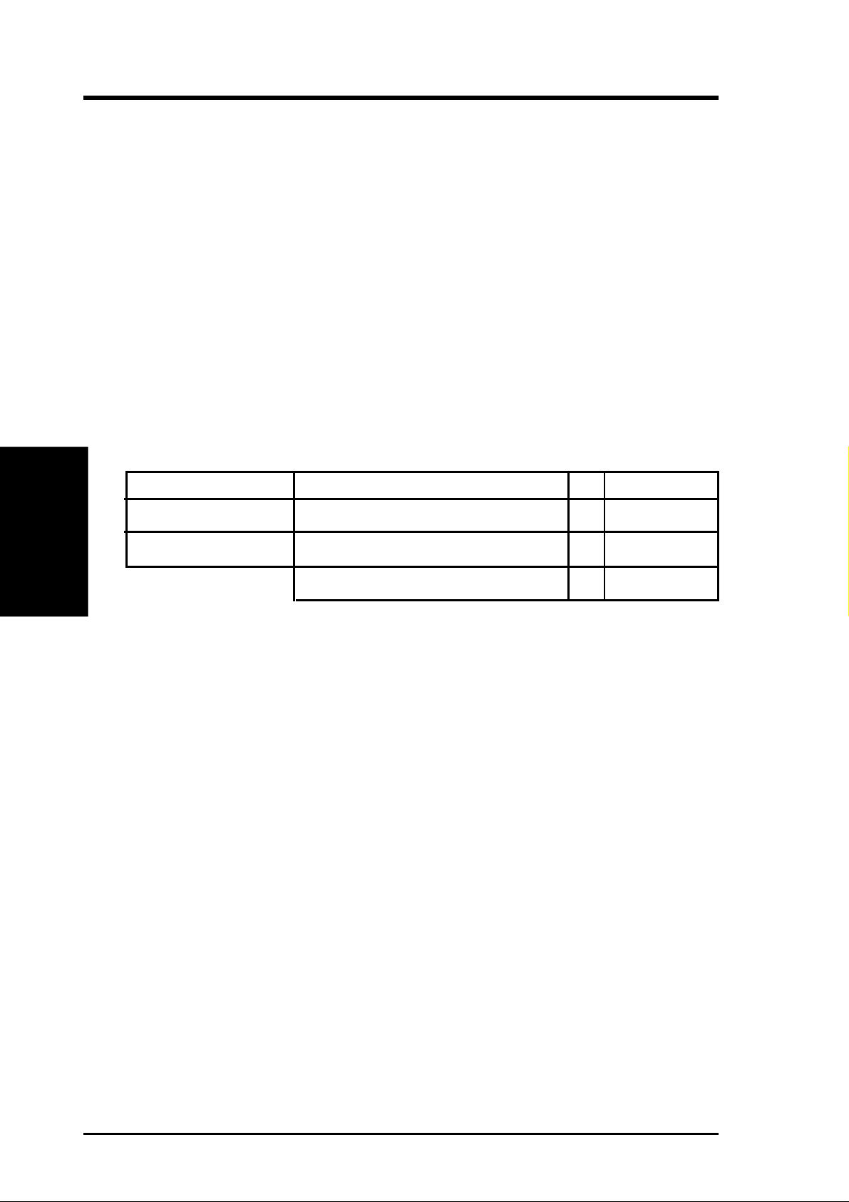
3.5.2 DIMM Installation
Insert the module(s) as shown. Because the number of pins are different on either
side of the breaks, the module will only fit in the orientation shown. DRAM SIMM
modules have the same pin contacts on both sides. SDRAM DIMMs have different
pin contacts on each side and therefore have a higher pin density.
Lock
88 Pins
®
60 Pins
P3B-1394
20 Pins
P3B-1394 168-Pin DIMM Memory Sockets
The DIMMs must be 3.3Volt unbuffered SDRAMs. To determine the DIMM type,
check the notches on the DIMMs (see figure below).
168-Pin DIMM Notch Key Definitions (3.3V)
DRAM Key Position
RFU
Buffered
Unbuffered
Voltage Key Position
5.0V
Reserved
3.3V
3. H/W SETUP
System Memory
The notches on the DIMM will shift between left, center, or right to identify the type
and also to prevent the wrong type from being inserted into the DIMM slot on the
motherboard. You must tell your retailer the correct DIMM type before purchasing.
This motherboard supports four clock signals per DIMM.
ASUS P3B-1394 User’s Manual 21
Page 22
3. HARDWARE SETUP
3.6 Central Processing Unit (CPU)
NOTE: The following pictures are provided for reference purposes only. The appearance of your retention mechanism and fan may be different from the examples.
3. H/W SETUP
CPU
Your motherboard provides a Slot 1 connector for a Pentium
®
III processor packaged in a Single Edge Contact Cartridge (SECC2), a Pentium® II processor packaged in SECC2/SECC, or a Celeron™ processor packaged in a Single Edge Processor Package (SEPP). An ASUS S370 CPU card can allow Socket 370 processors to
be used on any ASUS motherboard with the Slot 1 connector (See 7.2 S370 Series
CPU Cards for instructions on using this card).
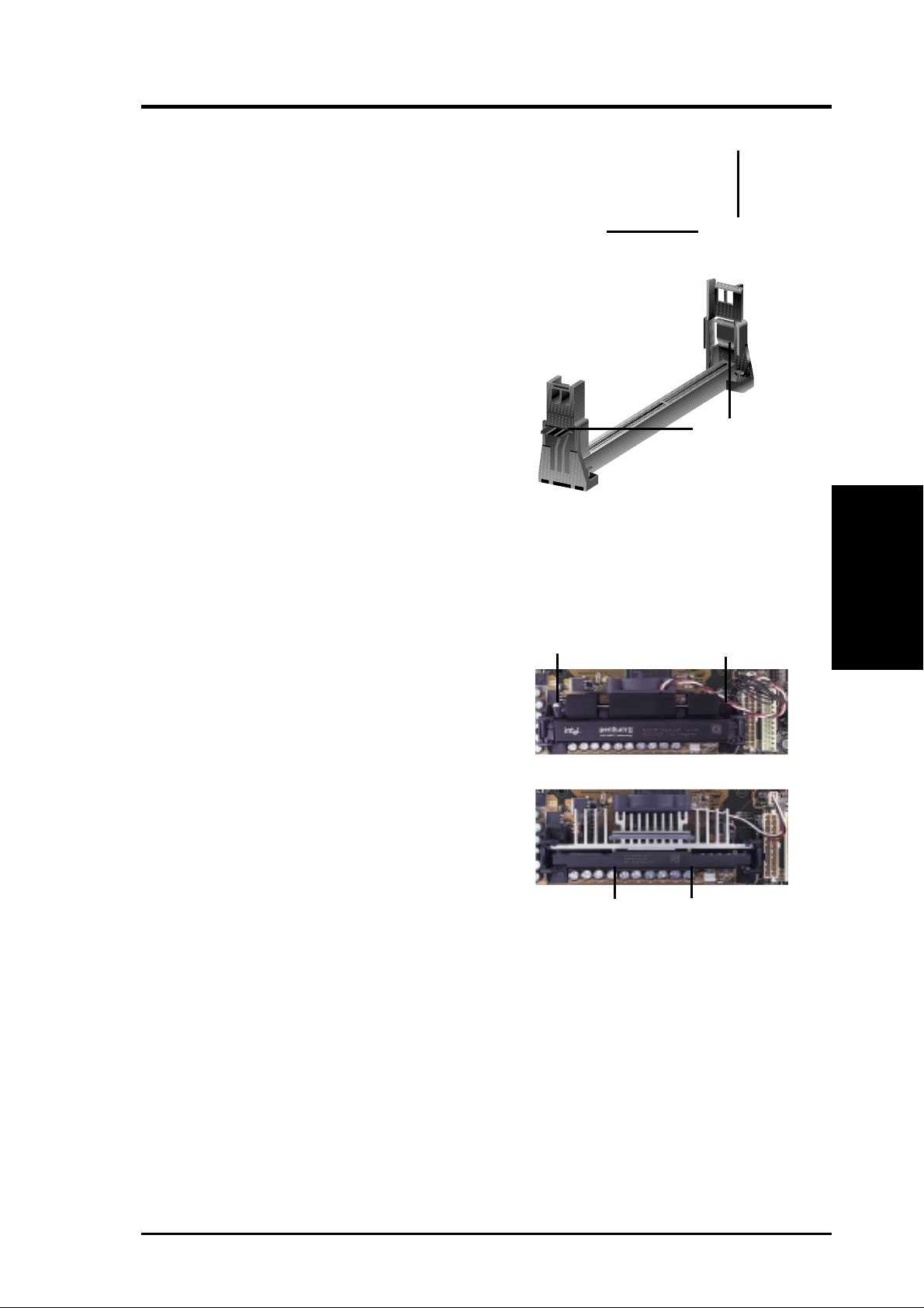
Pentium II processor packaged in an SECC with
heatsink and fan (top view)
Pentium III (in an SECC2) with heatsink and fan
NOTE: The SEPP fan (for Celeron processors) is
similar to SECC2 fan except that the clamping
design is different.
3.6.1 Universal Retention Mechanism
Your motherboard comes preinstalled
with a Universal Retention Mechanism
(URM). The URM supports Pentium III /
II and Celeron processors.
Universal Retention Mechanism (URM)
3.6.2 Heatsinks
The recommended heatsinks (see 3.6.4 Recommended Heatsinks for Slot 1 Proces-
sors) for the boxed Pentium III / II and Celeron processors are those with three-pin
fans that can be connected to the fan connectors on the motherboard.
WARNING! Be sure that there is sufficient air circulation across the processor’s
heatsink by regularly checking that your CPU fan is working. W ithout sufficient
circulation, the processor could overheat and damage both the processor and the
motherboard. You may install an auxiliary chassis fan, if necessary.
22
ASUS P3B-1394 User’s Manual
Page 23
3. HARDWARE SETUP
3.6.3 Installing the Processor
1. Unlock the URM’s Folding Support Arms:
The folding support arms of the URM are
locked when shipped.
T o unlock the support arms, simply flip them
up to an upright position.
Locked Folding
Support Arms
The URM is now ready for the installation
Unlocked Folding
Support Arms
of your processor.
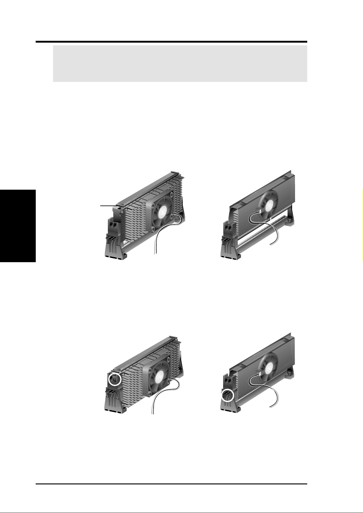
2. Attach the Heatsink
NOTE: If provided, you should follow the heatsink attachment instructions
that came with your heatsink or processor. The following steps are provided
only as a general guide and may not reflect those for your heatsink.
Using the SECC fan with the Pentium
®
II
Lock Arm
Lock Arm
Push the two lock arms in one direction to
clamp the heatsink onto the processor and the
other direction to release.
Using the SECC2 fan with the Pentium
®
III
Insert the four heatsink’s pins through the
holes of the SECC2. Place the metal clip on
the ends of the pins and slide until it locks
into place.
Four Pins and metal clip
CPU
3. H/W SETUP
NOTE: The SEPP heatsink and fan (for Intel Celeron processors) is similar to
the SECC2 heatsink and fan except that the clamping design is different.
ASUS P3B-1394 User’s Manual 23
Page 24
3. HARDWARE SETUP
W ARNING! Make sure the heatsink is mounted tightly against the SECC2, SECC,
or SEPP; otherwise, the CPU will overheat. You may install an auxiliary fan to
provide adequate circulation across the processor’s passive heatsink.
3. Insert the SECC2/SECC/SEPP
3. H/W SETUP
CPU
SECC with Pentium
®
II only: Push the SECC’s two locks inward until you hear
a click (the picture in step 2 shows the locks in the outward position and inward in
the picture below).
With the heatsink facing the motherboard’s chipset, push the SECC2, SECC, or
SEPP gently but firmly into the Slot 1 connector until it is fully inserted.
SECC
Push lock inward
CPU fan cable to
fan connector
SECC2/SEPP
CPU fan cable to
fan connector
4. Secure the SECC2/SECC/SEPP
Secure the SECC2/SECC/SEPP in place by pushing the SECC2/SECC/SEPP
until it is firmly seated on the Slot 1 connector.
SECC with Pentium
®
II only: The SECC locks should be outward when se-
cured so that the lock shows through the retention mechanism’s lock holes.
SECC SECC2/SEPP
Lock hole
Lock hole
CPU fan cable to
fan connector
CPU fan
cable to fan
connector
24 ASUS P3B-1394 User’s Manual
Page 25
3. HARDWARE SETUP
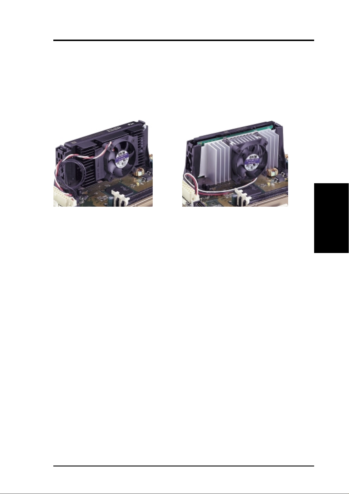
3.6.4 Recommended Heatsinks for Slot 1 Processors
The recommended heatsinks for the Slot 1 processors are those with three-pin fans,
such as the ASUS Smart Fan, that can be connected to the motherboard’s CPU fan
connector . These heatsinks dissipate heat more efficiently and with an optional hardware monitor, they can monitor the fan’s RPM and use the alert function with the
Intel LANDesk Client Manager (LDCM) or the ASUS PC Probe software.
SECC Heatsink & Fan SECC2 Heatsink & Fan
NOTE: The SEPP heatsink and fan (for Intel Celeron processors) is similar to the
SECC2 heatsink and fan except that the clamping design is different.
CPU
3. H/W SETUP
ASUS P3B-1394 User’s Manual 25
Page 26
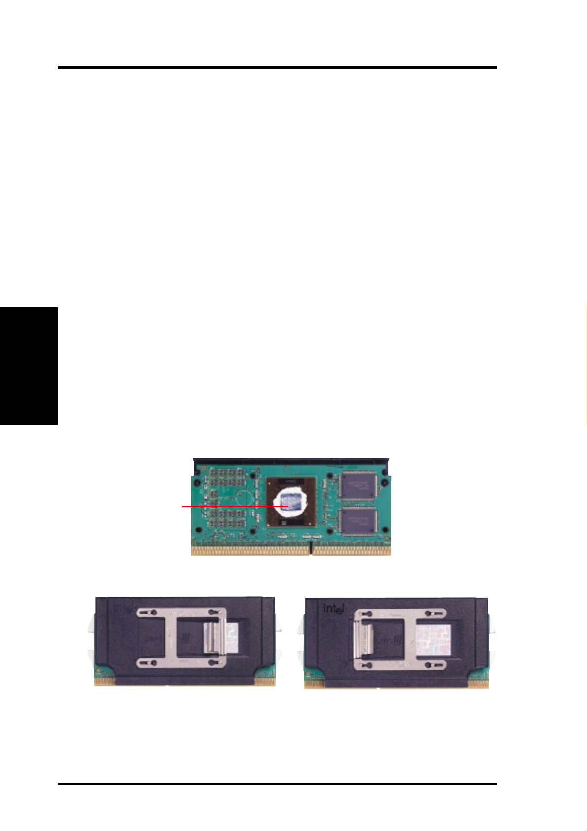
3.6.5 Precautions
Operating a processor at temperatures above its maximum specified operating temperature will shorten the processor lifetime and may cause unreliable operation. To
prevent system overheat and/or damage, it is important to have accurate temperature readings of the processor core (the main source of power dissipation) for system thermal management. Included inside Pentium III, Pentium II (Deschutes), and
PPGA370 Celeron processors is a thermal sensor that is connected to the internal
thermal diode.
Unlike other motherboards, this motherboard was designed to acquire thermal data
directly from the processor thermal diode. Therefore, the CPU temperature reported
may be higher than those from motherboards that take readings from thermal sensors external to the processor. This is not a cause for alarm. If, however, the BIOS
and/or your hardware monitoring program is reporting a CPU temperature above
the threshold, check the following:
3. H/W SETUP
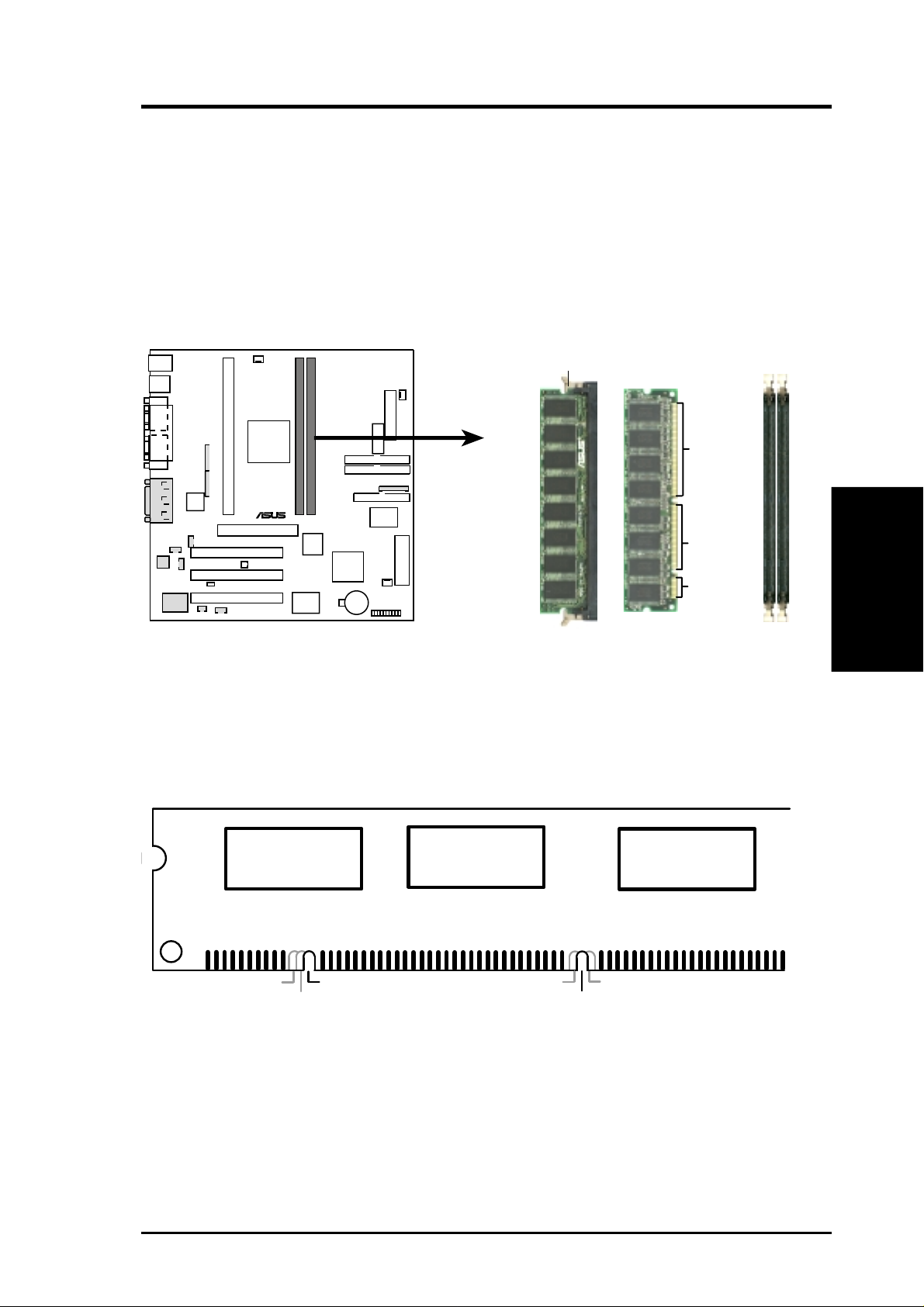
3. HARDWARE SETUP
CPU
1. An Intel recommended fan heatsink is used.
2. Good quality thermal interface material is used.
3. The heatsink is correctly installed onto the processor with a strong retention clip.
4. There is no visible gap between the processor die and heatsink.
The thermal interface material
should be continuous with no
through-holes or debris.
Example of a correctly installed retention clip
Example of an incorrectly installed retention clip
26 ASUS P3B-1394 User’s Manual
Page 27

3. HARDWARE SETUP
3.7 Expansion Cards
WARNING! Unplug your power supply when adding or removing expansion
cards or other system components. Failure to do so may cause severe damage to
both your motherboard and expansion cards.
3.7.1 Expansion Card Installation Procedure
1. Read the documentation for your expansion card and make any necessary hardware or software settings for your expansion card, such as jumpers.
2. Remove your computer system’s cover and the bracket plate on the slot you
intend to use. Keep the bracket for possible future use.
3. Carefully align the card’s connectors and press firmly.
4. Secure the card on the slot with the screw you removed above.
5. Replace the computer system’s cover.
6. Set up the BIOS if necessary
(such as IRQ xx Used By ISA: Yes in PNP AND PCI SETUP)
7. Install the necessary software drivers for your expansion card.
3.7.2 Assigning IRQs for Expansion Cards
IMPORTANT: Interrupt requests are shared as shown by the following table:
INT-A INT-B INT-C INT-D
PCI slot 1 -- -- -- -PCI slot 2 -- -- shared -PCI slot 3 -- -- -- shared
Audio -- -- -- shared
1394 -- -- shared -AGPslot -- -- -- --
If using PCI cards on shared slots, make sure that the drivers support “Share IRQ” or
that the cards do not need IRQ assignments. Conflicts will arise between the two
PCI groups that will make the system unstable or cards inoperable.
Some expansion cards need to use an IRQ to operate. Generally, an IRQ must be
exclusively assigned to one use. In a standard design, there are 16 IRQs available
but most of them are already in use, leaving 6 IRQs free for expansion cards. If your
motherboard has PCI audio onboard, an extra IRQ will be used, leaving 5 IRQs
free. If your motherboard has ISA audio onboard, an extra 3 IRQs will be used,
leaving 3 IRQs free.
3. H/W SETUP
Expansion Cards
Both ISA and PCI expansion cards may require the use IRQs. System IRQs are
available to cards installed in the ISA expansion bus first, then any remaining IRQs
are available to PCI cards. Currently, there are two types of ISA cards. The original
ISA expansion card design, now referred to as legacy ISA cards, requires that you
configure the card’s jumpers manually and then install it in an available slot on the
ISA bus. To see a map of your used and free IRQs in Windows 98, the Control
Panel icon in My Computer, contains a System icon, which gives you a Device
ASUS P3B-1394 User’s Manual 27
Page 28
Manager tab. Double-clicking on a specific hardware device gives you the Re-
sources tab which shows the Interrupt number and address. Make sure that no two
devices use the same IRQ or your computer will experience problems when those
two devices are in use at the same time.
To simplify this process, this motherboard complies with the Plug and Play (PnP)
specification, which was developed to allow automatic system configuration whenever a PnP-compliant card is added to the system. For PnP cards, IRQs are assigned
automatically from those available.
If the system has both Legacy and PnP ISA cards installed, IRQs are
assigned to PnP cards from those not used by Legacy cards. The PCI and PnP configuration of the BIOS setup utility can be used to indicate which IRQs are being
used by Legacy cards. For older Legacy cards that do not work with the BIOS, you
can contact your vendor for an ISA Configuration Utility.
An IRQ number is automatically assigned to PCI expansion cards after those used
by Legacy and PnP ISA cards. In the PCI bus design, the BIOS automatically assigns an IRQ to PCI cards that require an IRQ. To install a PCI card, you need to set
3. H/W SETUP
DMA Channels
something called the INT (interrupt) assignment. Since all the PCI slots on this
motherboard use an INTA #, be sure that the jumpers on your PCI cards are set to
INT A.
3. HARDWARE SETUP
3.7.3 Assigning DMA Channels for ISA Cards
Some ISA cards, both legacy and PnP, may also need to use a DMA (Direct Memory
Access) channel. DMA assignments for this motherboard are handled the same way
as the IRQ assignment process described earlier. You can select a DMA channel in
the PCI and PnP configuration section of the BIOS Setup utility.
IMPORTANT: To avoid conflicts, reserve the necessary IRQs and DMAs for legacy
ISA cards (see 4.7 PNP and PCI Setup, choose Yes in IRQ xx Used By ISA and DMA
x Used By ISA for those IRQs and DMAs you want to reserve).
3.7.4 Accelerated Graphics Port (AGP)
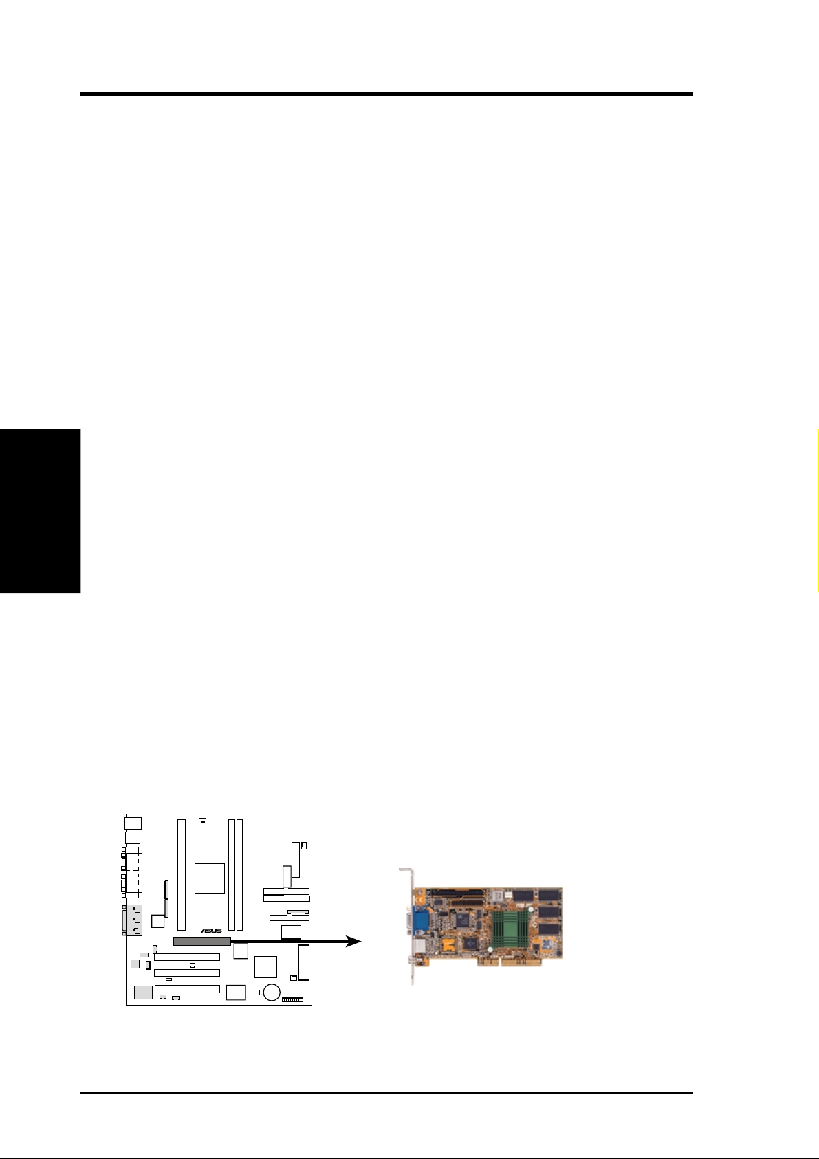
This motherboard provides an accelerated graphics port (AGP) slot to support a new
generation of graphics cards with ultra-high memory bandwidth, such as an ASUS
3D Hardware Accelerator.
®
P3B-1394
P3B-1394 Accelerated Graphics Port (AGP)
28 ASUS P3B-1394 User’s Manual
Page 29
3. HARDWARE SETUP
3.8 External Connectors
WARNING! Some pins are used for connectors or power sources. These are
clearly distinguished from jumpers in the motherboard layout. Placing jumper
caps over these connectors will cause damage to your motherboard.
IMPORTANT: Ribbon cables should always be connected with the red stripe to
Pin 1 on the connectors. Pin 1 is usually on the side closest to the power connector on hard drives and CD-ROM drives, but may be on the opposite side on
floppy disk drives. Check the connectors before installation because there may
be exceptions. IDE ribbon cables must be less than 46 cm (18 in.), with the
second drive connector no more than 15 cm (6 in.) from the first connector.
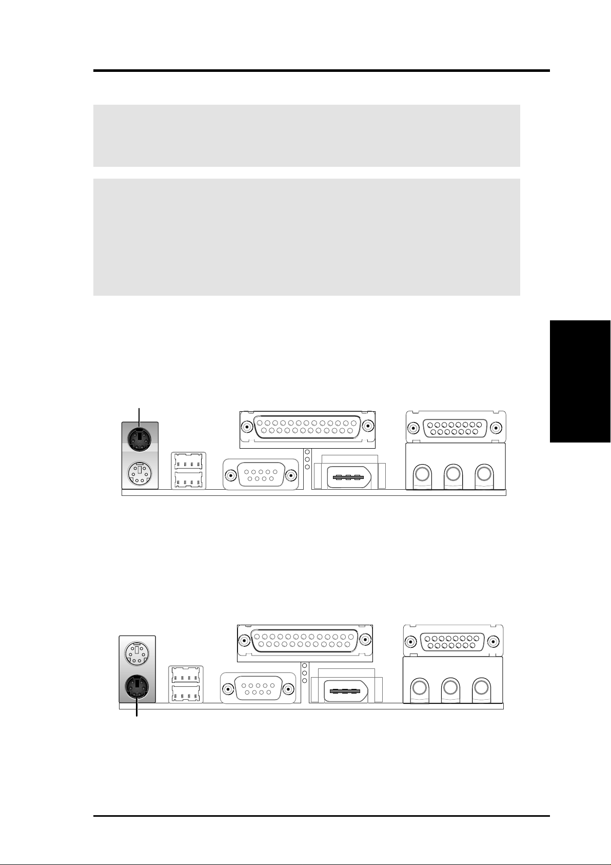
1) PS/2 Mouse Connector (6-pin PS2KBMS)
The system will direct IRQ12 to the PS/2 mouse if one is detected. If not detected, expansion cards can use IRQ12. See PS/2 Mouse Function Control in
4.4 BIOS Features Setup.
PS/2 Mouse (6-pin Female)
2) PS/2 Keyboard Connector (6-pin PS2KBMS)
This connection is for a standard keyboard using an PS/2 plug (mini DIN). This
connector will not allow standard AT size (large DIN) keyboard plugs. You
may use a DIN to mini DIN adapter on standard AT keyboards.
Connectors
3. H/W SETUP
PS/2 Keyboard (6-pin Female)
ASUS P3B-1394 User’s Manual 29
Page 30
3. H/W SETUP
Connectors
3. HARDWARE SETUP
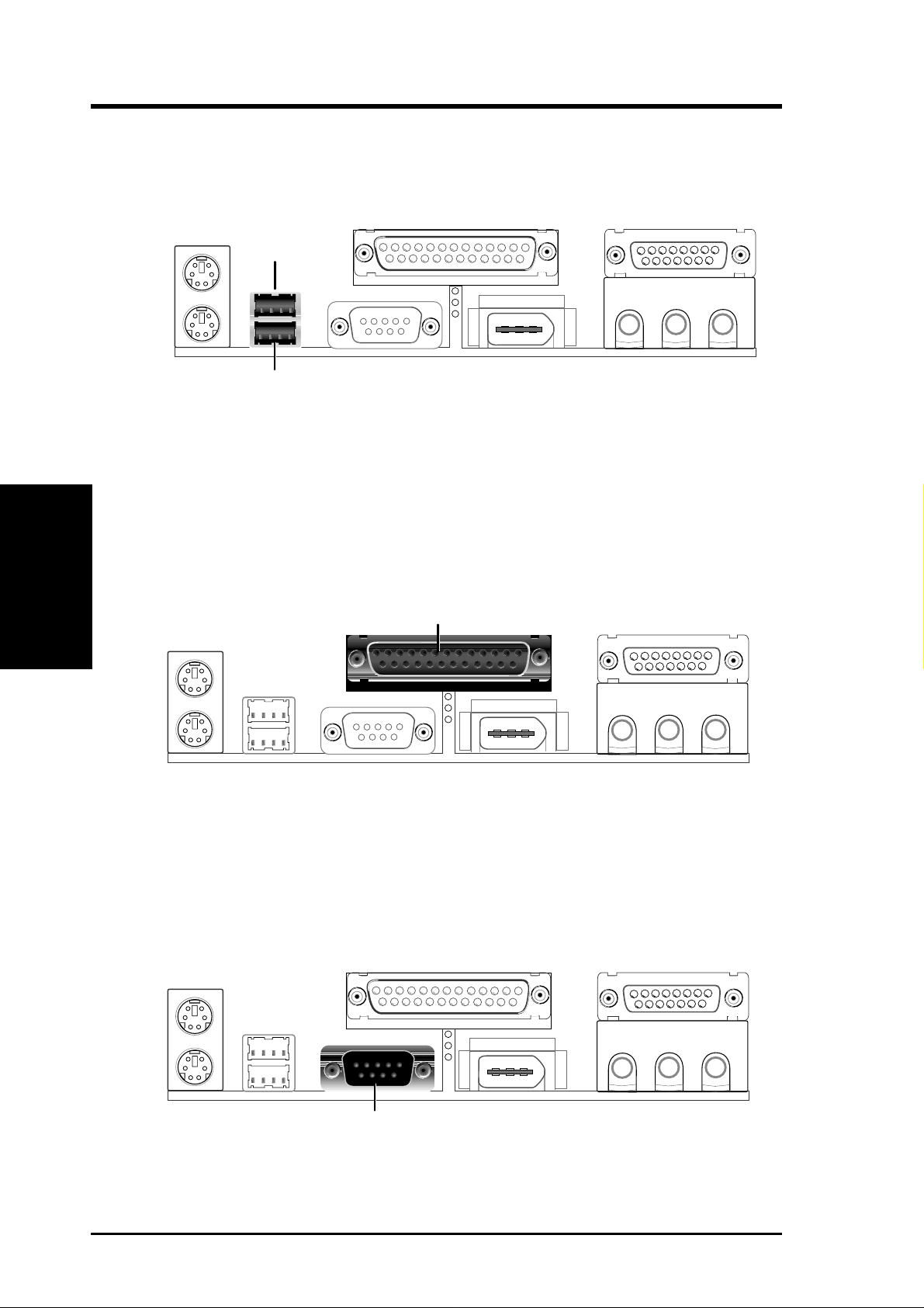
3) Universal Serial Bus Connectors 1 & 2 (Two 4-pin USB)
Two USB ports are available for connecting USB devices.
USB 1
Universal Serial Bus (USB) 2
4) Parallel Port Connector (25-pin PRINTER)
You can enable the parallel port and choose the IRQ through Onboard Parallel
Port in 4.5 Chipset Features Setup. NOTE: Serial printers must be connected
to the serial port.
Parallel (Printer) Port (25-pin Female)
5) Serial Port Connectors (9-pin COM1)
The serial port can be used for pointing devices or other serial devices. See
Onboard Serial Port 1 in 4.5 Chipset Features Setup.
Serial Port (9-pin Male) COM 1
30 ASUS P3B-1394 User’s Manual
Page 31

3. HARDWARE SETUP
6) IEEE-1394 Connector (6-pin 1394_CON)
This connector supports external devices with a 6-pin IEEE-1394 connector.
IEEE-1394 (6 pins)
7) Joystick/MIDI Connector (15-pin GAME_AUDIO) (with optional onboard audio)
You may connect game joysticks or game pades to this connector for playing
games. Connect MIDI devices for playing or editing audio.
Joystick/Midi (15-pin Female)
8) Audio Port Connectors (Three 1/8” Female) (with optional onboard audio)
Line Out can be connected to headphones or preferably powered speakers.
Line In allows tape players or other audio sources to be recorded by your com-
puter or played through the Line Out. Mic allows microphones to be connected
for inputting voice.
Connectors
DMA Channels
3. H/W SETUP
3. H/W SETUP
MicLine InLine Out
1/8" Stereo Audio Connectors
ASUS P3B-1394 User’s Manual 31
Page 32
3. H/W SETUP
Connectors
3. HARDWARE SETUP
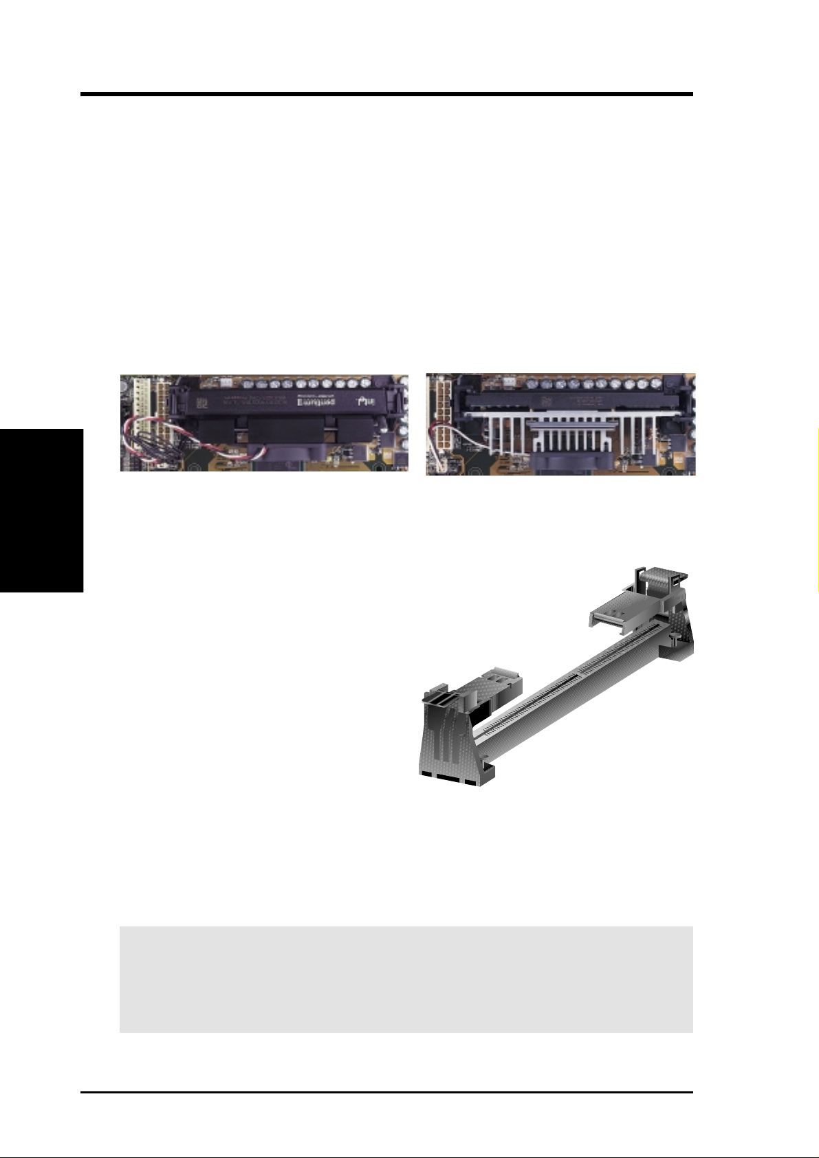
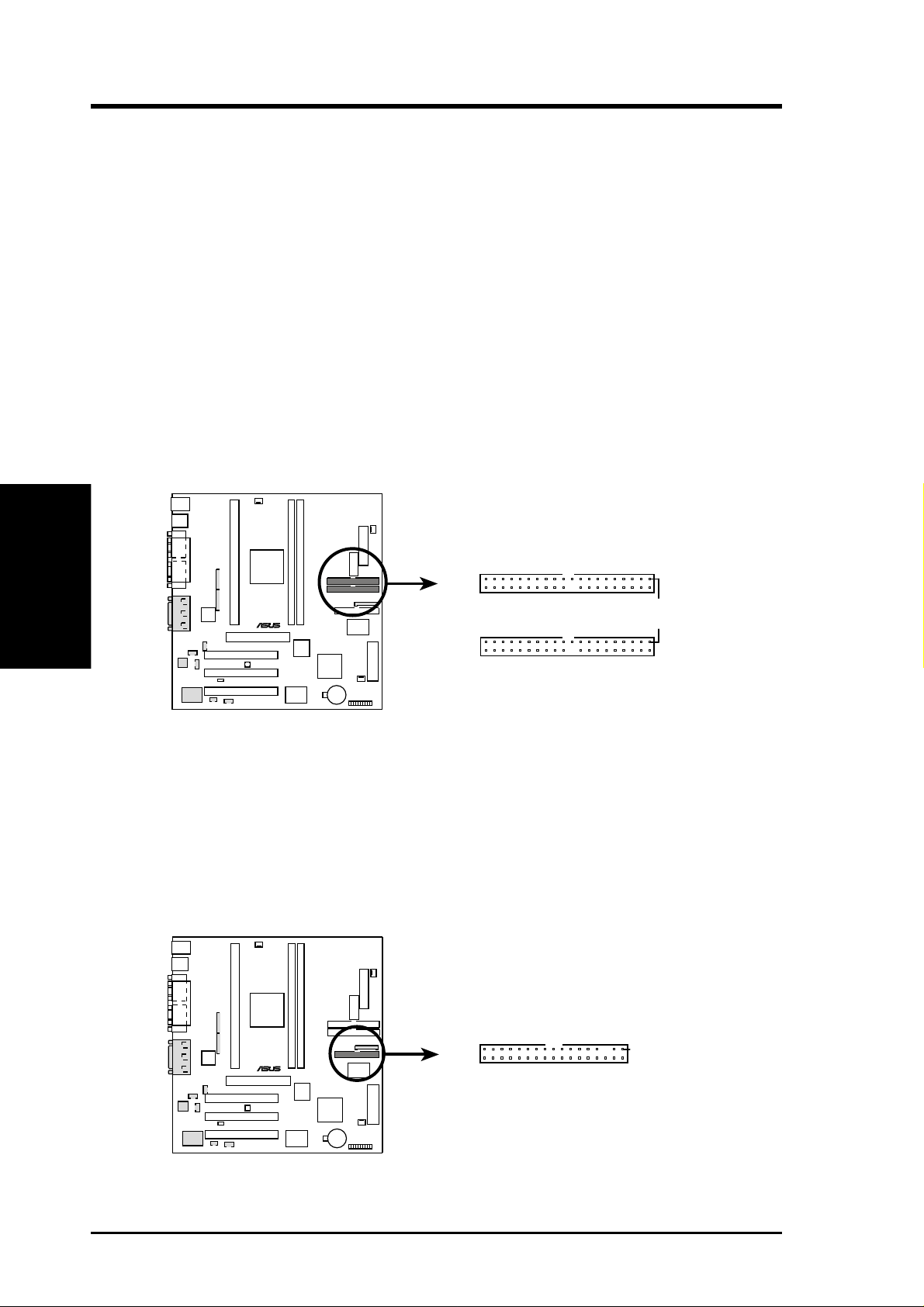
9) IDE Connectors (Two 40-1pin PRIMARY/SECONDARY IDE)
These connectors support the provided IDE hard disk ribbon cable. After connecting the single end to the board, connect the two plugs at the other end to your hard
disk(s). If you install two hard disks, you must configure the second drive to Slave
mode by setting its jumper accordingly. Refer to the documentation of your hard
disk for the jumper settings. BIOS now supports SCSI device or IDE CD-ROM
bootup (see HDD Sequence SCSI/IDE First and Boot Sequence in 4.4 BIOS
Features Setup). (Pin 20 is removed to prevent inserting in the wrong orienta-
tion when using ribbon cables with pin 20 plugged).
TIP: You may configure two hard disks to be both Masters with two ribbon
cables – one for the primary IDE connector and another for the secondary IDE
connector . You may install one operating system on an IDE drive and another on
a SCSI drive and select the boot disk through Boot Sequence in 4.4 BIOS Fea-
tures Setup.
NOTE: Orient the red markings (usually zigzag)
on the IDE ribbon cable to pin 1
Secondary IDE Connector
®
P3B-1394
P3B-1394 IDE Connectors
Primary IDE Connector
Pin 1
10) Floppy Disk Drive Connector (34-1pin FLOPPY)
This connector supports the provided floppy disk drive ribbon cable. After connecting the single end to the board, connect the two plugs on the other end to the
floppy drives. (Pin 5 is removed to prevent inserting in the wrong orienta-
tion when using ribbon cables with pin 5 plugged).
Floppy Disk Drive Connector
®
P3B-1394
P3B-1394 Floppy Disk Drive Connector
32 ASUS P3B-1394 User’s Manual
Pin 1
Page 33

3. HARDWARE SETUP
11) Chassis,Power Supply ,CPU Fan Connectors (3-pin CHA_,PWR_,CPU_FAN)
These connectors support cooling fans of 500mA (6W) or less. Orientate the
fans so that the heat sink fins allow airflow to go across the onboard heat sink(s)
instead of the expansion slots. Depending on the fan manufacturer, the wiring
and plug may be different. The red wire should be positive, while the black
should be ground. Connect the fan’s plug to the board taking into consideration
the polarity of the connector. NOTE: The “Rotation” signal is to be used only
by a specially designed fan with rotation signal. The Rotations per Minute (RPM)
can be monitored using ASUS PC Probe Utility or Intel LDCM Utility (see 6.
Software Reference).
WARNING! The CPU and/or motherboard will overheat if there is no airflow
across the CPU and onboard heatsinks. Damage may occur to the motherboard
and/or the CPU fan if these pins are incorrectly used. These are not jumpers,
do not place jumper caps over these pins.
®
P3B-1394
P3B-1394 12Volt Cooling Fan Power
CPU Fan Power (CPU_FAN)
GND
Rotation
+12V
Power Supply Fan (PWR_FAN)
GND
+12V
Rotation
Chassis Fan Power (CHA_FAN)
GND
+12V
Rotation
Connectors
3. H/W SETUP
ASUS P3B-1394 User’s Manual 33
Page 34

3. HARDWARE SETUP
12) Wake-On-LAN Connector (3-pin WOL_CON)
The WOL_CON connector powers up the system when a wake-up packet or
signal is received from the network through the ASUS PCI-L101 LAN card.
IMPORTANT: This feature requires that Wake On LAN is set to Enabled (see
4.6 Power Management Setup) and that your system has an ATX power supply
with at least 720mA +5V standby power.
3. H/W SETUP
Connectors
®
P3B-1394
WOL_CON
Ground
+5 VSB
PME
P3B-1394 Wake-On-LAN Connector
13) Wake-On-Ring Connector (2-pin WOR)
This connector connects to an internal modem card with a Wake-On-Ring output. The connector powers up the system when a ringup packet or signal is received through the internal modem card. NOTE: For external modems, WakeOn-Ring is detected through the COM port.
IMPORTANT: This feature requires that PWR Up On Modem Act is set to
Enabled (see 4.6 Power Management Setup).
Pin 1 Ground
Pin 2 PIXRI#
®
WOR
P3B-1394
P3B-1394 Wake-On-Ring Connector
34 ASUS P3B-1394 User’s Manual
Page 35

3. HARDWARE SETUP
14) IEEE-1394 Headers (8-pin 1394HEAD2/1394HEAD3)
These headers can support an IEEE-1394 serial connector cable set that mounts
to the front of a case with a 1394 connector slot for easy accessibility or an
IEEE-1394/COM2 combination serial connector cable set that mounts to a free
expansion slot at the back of your case. You can also connect 1394-compliant
internal fixed-disk drives to these headers. NOTE: To use these headers, set
Onboard 1394 to Enabled (see 4.7 PNP and PCI Setup)
+12V
Ground
TPB2TPB2+
TPA2TPA2+
Ground
Ground
+12V
®
P3B-1394
Ground
TPB2TPB2+
TPA2TPA2+
Ground
1394HEAD3 1394HEAD2
Ground
P3B-1394 IEEE-1394 Headers
15) Internal Audio Connectors (4-pin MODEM, CD_IN, AUX_CON, VIDEO)
These connectors allow you to receive stereo audio input from sound sources,
such as a CD-ROM, TV tuner, or MPEG card. The MODEM connector allows
the onboard audio to interface with a voice modem card with a similar connector. It also allows the sharing of microphone and speaker between the onboard
audio and the voice modem card.
Left Audio Channel
Ground
Ground
Right Audio Channel
CD_IN
VIDEO
Right Audio Channel
Left Audio Channel
Ground
Ground
®
P3B-1394
Ground
Modem-Out
Modem-In
Ground
MODEM
Right Audio Channel
Left Audio Channel
Ground
Ground
AUX_CON
Connectors
3. H/W SETUP
P3B-1394 Internal Audio Connectors
ASUS P3B-1394 User’s Manual 35
Page 36

3. HARDWARE SETUP
For items 16-23
3. H/W SETUP
Connectors
®
P3B-1394
Keyboard Lock
Message LED
Keylock
MSGLED-
MSGLED+
Ground
IDELED-
PWRBTN
ATX Power
Switch*
IDELED
*
Requires an ATX power supply.
Ground
Ground
ExtSMI#
IDELED+
PWRLED+
Power LED
SMI Lead
Speaker
Connector
Speaker
+5V
Reset Ground
Ground
PWRLED-
PWRLEDB-
Reset SW
P3B-1394 System Panel Connections
16) System Message LED Lead (2-pin MLED)
The LED connected to this lead indicates the state of the system. The LED lights
when the system is in suspend mode and is OFF otherwise.
17) Keyboard Lock Switch Lead (2-pin KEYLOCK)
This 2-pin connector connects to the case-mounted key switch to allow keyboard
locking. NOTE: When the keyboard is locked, the mouse can still be used.
18) System Management Interrupt Lead (2-pin SMI)
This allows the user to manually place the system into a suspend mode or “Green”
mode where system activity will be instantly decreased to save electricity and
expand the life of certain components when the system is not in use. This 2-pin
connector (see the preceding figure) connects to the case-mounted suspend switch.
If you do not have a switch for the connector, you may use the “Turbo Switch”
since it does not have a function. SMI is activated when it detects a short to open
moment and therefore leaving it shorted will not cause any problems. This may
require one or two pushes depending on the position of the switch.
19) System Warning Speaker Connector (4-pin SPEAKER)
This 4-pin connector connects to the case-mounted speaker.
20) ATX Power Switch / Soft-Off Switch Lead (2-pin PWR)
The system power is controlled by a momentary switch connected to this lead.
Pushing the button once will switch the system between ON and SLEEP or ON
and SOFT OFF, depending on your BIOS or OS setting. Pushing the switch
while in the ON mode for more than 4 seconds will turn the system off. The
system power LED shows the status of the system’s power.
36 ASUS P3B-1394 User’s Manual
Page 37

3. HARDWARE SETUP
21) IDE Activity LED Lead (2-pin IDELED)
This 2-pin connector supplies power to the cabinet’s IDE activity LED. Read
and write activity by devices connected to the Primary or Secondary IDE connectors will cause the LED to light up.
22) System Power LED Lead (3-1 pin PLED)
This 3-1 pin connector connects to the system power LED, which lights when
the system is powered ON and turns OFF when it is in sleep or soft-off mode.
23) Reset Switch Lead (2-pin RESET)
This 2-pin connector connects to the case-mounted reset switch for rebooting
your computer without having to turn off your power switch. This is a preferred
method of rebooting to prolong the life of the system’s power supply.
24) ATX Power Supply Connector (20-pin A TXPWR)
This connector connects to an ATX power supply. The plug from the power
supply will only insert in one orientation because of the different hole sizes.
Find the proper orientation and push down firmly but gently making sure that
the pins are aligned.
®
P3B-1394
+12.0 Volts
+5V Standby
Power Good
Ground
+5.0 Volts
Ground
+5.0 Volts
Ground
+3.3 Volts
+3.3 Volts
+5.0 Volts
+5.0 Volts
-5.0 Volts
Ground
Ground
Ground
Power Supply On
Ground
-12.0 Volts
+3.3 Volts
P3B-1394 ATX Power Connector
IMPORTANT: Make sure that your ATX power supply can supply at least 10mA
on the 5-volt standby lead (5VSB). You may experience difficulty in powering
on your system if your power supply cannot support the load. For Wake-OnLAN and suspend-to-RAM support, your ATX power supply must supply at
least 720mA +5VSB.
Connectors
3. H/W SETUP
ASUS P3B-1394 User’s Manual 37
Page 38

3. HARDWARE SETUP
25) Serial Port Header (10-pin COM2)
The optional IEEE-1394 and serial combination cable with bracket can be used
to add an additional serial port for a second serial device. Connect the IEEE1394 cables from the 1394 CON board to the two IEEE-1394 headers
(1394HEAD2/1394HEAD3), the serial cable from the bracket to the COM2
header, and then mount the bracket to the chassis on a free expansion slot.
COM2
3. H/W SETUP
Connectors
RTS2#
DSA2#
110
+5V
CTS2#
®
P3B-1394
RI2#
-12V
TXD2
DCD2#
RXD2
DTA2#
P3B-1394 Serial COM2 Header
26) Digital Audio Interface Header (3-pin SPDIFOUT)
This header is the digital link between the motherboard and your devices, such
as CD player, sampler, or DAT recorder. It allows the digital transmission of
audio data in SPDIF (Sony/Philips Digital Interface) format.
SPDIFOUT
®
+5V
P3B-1394
Ground
SPDIFOUT
P3B-1394 Audio Digital Interface Connector
38 ASUS P3B-1394 User’s Manual
Page 39

3. HARDWARE SETUP
3.9 Power Connection Procedures
1. After all connections are made, close the system case cover.
2. Be sure that all switches are off (in some systems, marked with
3. Connect the power supply cord into the power supply located on the back of
your system case according to your system user’s manual.
4. Connect the power cord into a power outlet that is equipped with a surge protector .
5. You may then turn on your devices in the following order:
a. Your monitor
b. External SCSI devices (starting with the last device on the chain)
c. Your system power. For ATX power supplies, you need to switch
on the power supply as well as press the ATX power switch on the
front of the case.
6. The power LED on the front panel of the system case will light. For ATX power
supplies, the system LED will light when the ATX power switch is pressed. The
monitor LED may light up after the system’s if it complies with “green” stan-
dards or if it has a power standby feature. The system will then run power-on
tests. While the tests are running, additional messages will appear on the screen.
If you do not see anything within 30 seconds from the time you turn on the
power, the system may have failed a power-on test. Recheck your jumper settings and connections or call your retailer for assistance.
).
3. H/W SETUP
Power Connections
7. During power-on, hold down <Delete> to enter BIOS setup. Follow the instructions in 4. BIOS Setup
* Powering Off your computer: You must first exit or shut down your operating
system before switching off the power switch. For ATX power supplies, you can
press the ATX power switch after exiting or shutting down your operating system. If you use W indows 95, click the Start button, click Shut Down, and then
click Shut down the computer?. The power supply should turn off after Win-
dows shuts down.
NOTE: The message “You can now safely turn off your computer” will not
appear when shutting down with ATX power supplies.
ASUS P3B-1394 User’s Manual 39
Page 40

4. BIOS SETUP
4.1 Managing and Updating Your BIOS
4.1.1 Upon First Use of the Computer System
It is recommended that you save a copy of the original motherboard BIOS along
with a Flash Memory Writer utility (AFLASH.EXE) to a bootable floppy disk in
case you need to reinstall the BIOS later . AFLASH.EXE is a Flash Memory Writer
utility that updates the BIOS by uploading a new BIOS file to the programmable
flash ROM on the motherboard. This file works only in DOS mode. To determine
the BIOS version of your motherboard, check the last four numbers of the code
displayed on the upper left-hand corner of your screen during bootup. Larger numbers represent a newer BIOS file.
1. Type FORMAT A:/S at the DOS prompt to create a bootable system floppy
disk. DO NOT copy AUTOEXEC.BAT & CONFIG.SYS to the disk.
2. Type COPY D:\AFLASH\AFLASH.EXE A:\ (assuming D is your CD-ROM
drive) to copy AFLASH.EXE to the just created boot disk.
Flash Memory Writer
4. BIOS SETUP
NOTE: AFLASH works only in DOS mode. It will not work with DOS prompt
in Windows and will not work with certain memory drivers that may be loaded
when you boot from your hard drive. It it recommended that you reboot using a
floppy.
3. Reboot your computer from the floppy disk. NOTE: BIOS setup must specify
“Floppy” as the first item in the boot sequence.
4. In DOS mode, type A:\AFLASH <Enter> to run AFLASH.
IMPORTANT! If “unknown” is displayed after Flash Memory:, the memory chip is
either not programmable or is not supported by the ACPI BIOS and therefore, cannot be
programmed by the Flash Memory Writer utility.
ASUS P3B-1394 User’s Manual40
Page 41

4. BIOS SETUP
5. Select 1. Save Current BIOS to File from the Main menu and press <Enter>.
The Save Current BIOS To File screen appears.
6. Type a filename and the path, for example, A:\XXX-XX.XXX and then press
<Enter>.
4.1.2 Updating BIOS Procedures (only when necessary)
1. Download an updated ASUS BIOS file from the Internet (WWW or FTP) (see
ASUS CONTACT INFORMATION on page 3 for details) and save to the disk
you created earlier.
2. Boot from the disk you created earlier.
3. At the “A:\” prompt, type AFLASH and then press <Enter>.
4. At the Main Menu, type 2 and then press <Enter>. The Update BIOS Includ-
ing Boot Block and ESCD screen appears.
5. Type the filename of your new BIOS and the path, for example, A:\XXX-
XX.XXX, and then press <Enter>.
NOTE: To cancel this operation, press <Enter>.
4. BIOS SETUP
Flash Memory Writer
ASUS P3B-1394 User’s Manual 41
Page 42

4. BIOS SETUP
6. When prompted to confirm the BIOS update, press Y to start the update.
7. The utility starts to program the new BIOS information into the flash ROM. The
boot block will be updated automatically only when necessary. This will minimize the chance of a failed updating. When the programming is finished, Flashed
Successfully will be displayed.
4. BIOS SETUP
Updating BIOS
8. Follow the onscreen instructions to continue.
WARNING! If you encounter problems while updating the new BIOS, DO NOT
turn off your system since this might prevent your system from booting up. Just
repeat the process, and if the problem still persists, update the original BIOS file
you saved to disk above. If the Flash Memory Writer utility was not able to
successfully update a complete BIOS file, your system may not be able to boot
up. If this happens, your system will need servicing.
ASUS P3B-1394 User’s Manual42
Page 43
4. BIOS SETUP
4.2 BIOS Setup
The motherboard supports a 5-Volt programmable Flash ROM chip, which can be
updated when BIOS upgrades are released. Use the Flash Memory W riter utility to
download the new BIOS file into the ROM chip as described in detail in this section.
All computer motherboards provide a Setup utility program for specifying the system configuration and settings. If your motherboard came in a computer system, the
proper configuration entries may have already been made. If so, invoke the Setup
utility , as described later , and take note of the configuration settings for future refer ence; in particular, the hard disk specifications.
If you are installing the motherboard, reconfiguring your system or you receive a
Run Setup message, you will need to enter new setup information. This section
describes how to configure your system using this utility.
The BIOS ROM of the system stores the Setup utility. When you turn on the computer, the system provides you with the opportunity to run this program. This appears during the Power-On Self Test (POST). Press <F2> to call up the Setup utility .
If you are a little bit late pressing the mentioned key(s), POST will continue with its
test routines, thus preventing you from calling up Setup. If you still need to call
Setup, reset the system by pressing <Ctrl> + <Alt> + <Delete>, or by pressing the
Reset button on the system case. You can also restart by turning the system off and
then back on again, but do so only if the first two methods fail.
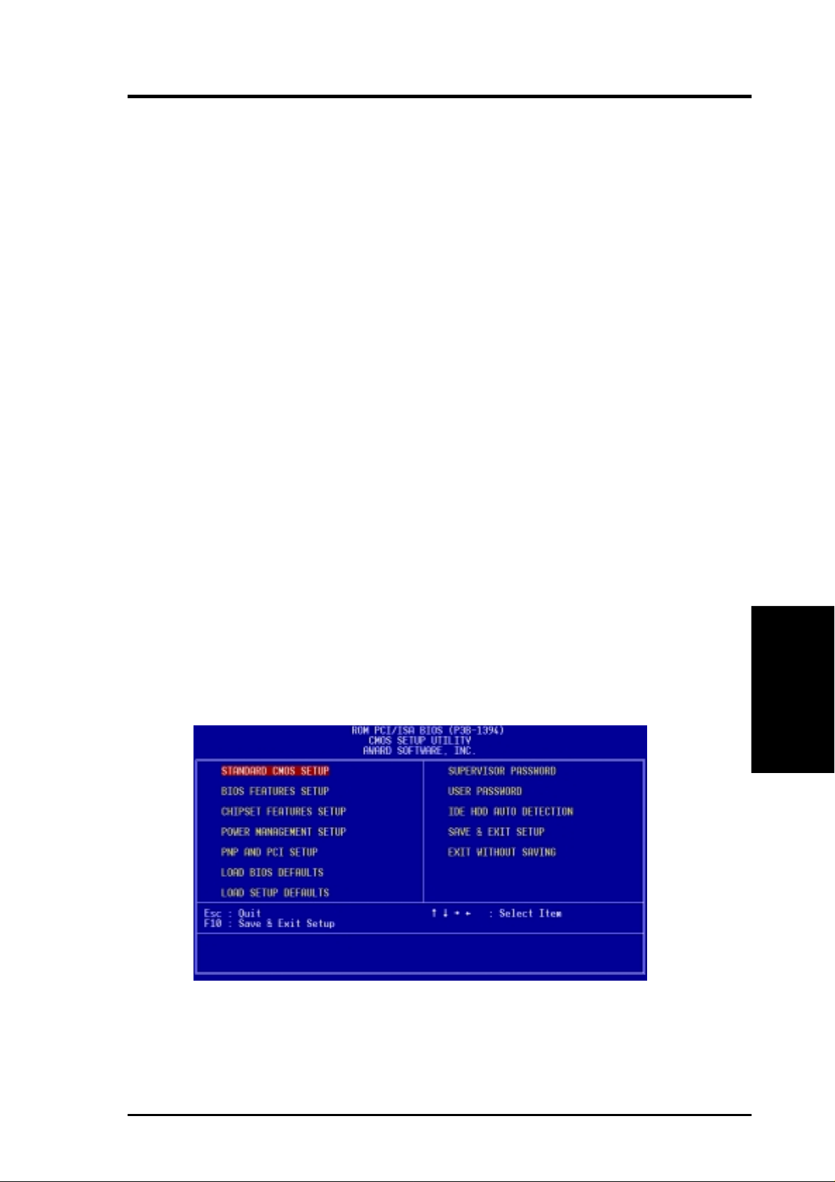
When you invoke Setup, the CMOS SETUP UTILITY main program screen will
appear with the following options:
BIOS Setup
4. BIOS SETUP
ASUS P3B-1394 User’s Manual 43
Page 44
4. BIOS SETUP
Load Defaults
The “Load BIOS Defaults” option loads the minimum settings for troubleshooting.
“Load Setup Defaults”, on the other hand, is for loading optimized defaults for
regular use. Choosing defaults at this level, will modify all applicable settings.
A section at the bottom of the above screen displays the control keys for this screen.
Take note of these keys and their respective uses. Another section just below the
control keys section displays information on the currently highlighted item in the list.
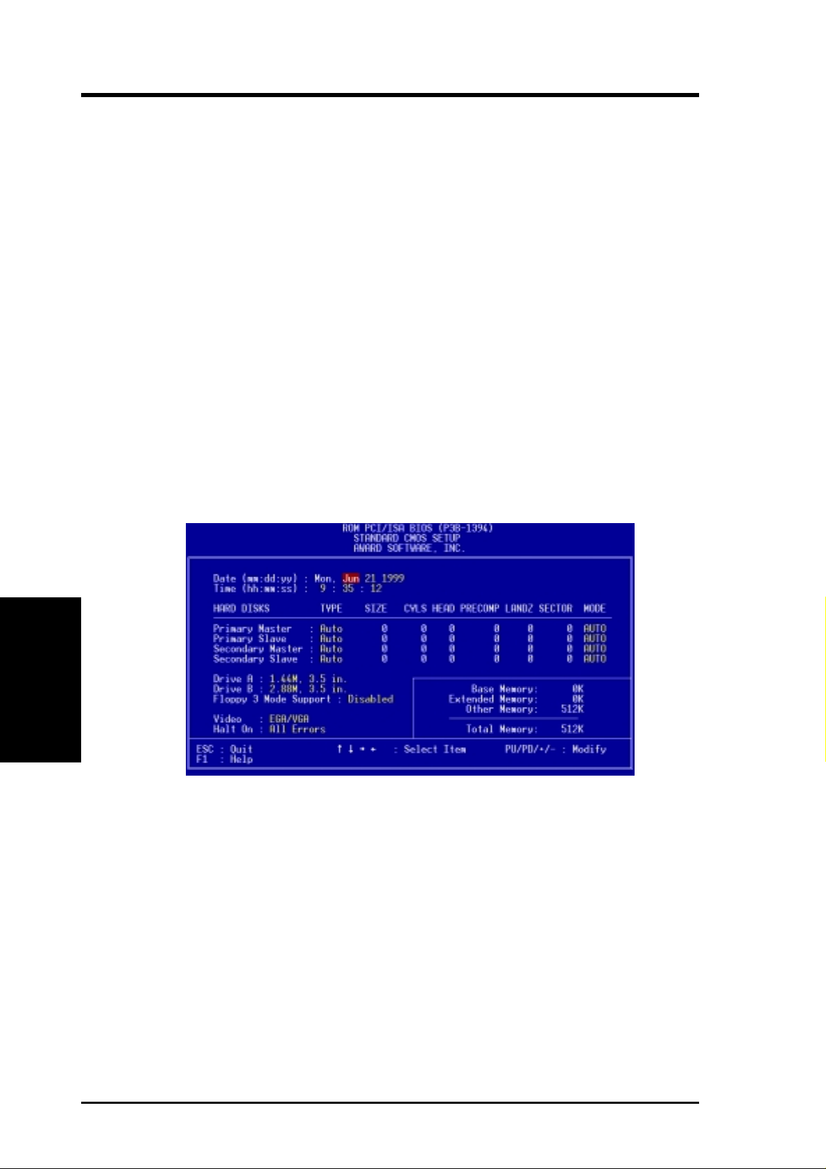
4.3 Standard CMOS Setup
This “Standard CMOS Setup” option allows you to record some basic system hardware configuration and set the system clock and error handling. If the motherboard
is already installed in a working system, you will not need to select this option
anymore. However, if the configuration stored in the CMOS memory on the board
gets lost or damaged, or if you change your system hardware configuration, you will
need to respecify the configuration values. The configuration values usually get lost
or corrupted when the power of the onboard CMOS battery weakens.
Standard CMOS
4. BIOS SETUP
The preceding screen provides you with a list of options. At the bottom of this screen
are the control keys for this screen. Take note of these keys and their respective uses.
User-configurable fields appear in a different color. If you need information on the
selected field, press <F1>. The help menu will then appear to provide you with the
information you need. The memory display at the lower right-hand side of the screen
is read-only and automatically adjusts accordingly.
Details of Standard CMOS Setup:
Date
T o set the date, highlight the “Date” field and then press either <Page Up>/<Page Down>
or <+>/<–> to set the current date. Follow the month, day and year format. Valid values
for month, day and year are: Month: (1 to 12), Day: (1 to 31), Year: (up to 2079)
ASUS P3B-1394 User’s Manual44
Page 45

4. BIOS SETUP
Time
T o set the time, highlight the “T ime” field and then press either <Page Up>/<Page Down>
or <+>/<–> to set the current time. Follow the hour, minute and second format. Valid
values for hour, minute and second are: (Hour: (00 to 23), Minute: (00 to 59), Second:
(00 to 59). Press <Enter> twice if you do not want to modify the current time.
NOTE: You can bypass the date and time prompts by creating an AUT OEXEC.BA T
file. For information on how to create this file, please refer to the MS-DOS manual.
Hard Disks
This field records the specifications for all non-SCSI hard disk drives installed in
your system. The onboard PCI IDE connectors provide Primary and Secondary
channels for connecting up to four IDE hard disks or other IDE devices. Each channel can support up to two hard disks; the first of which is the “master” and the
second is the “slave”.
Specifications for SCSI hard disks need not to be entered here since they operate
using device drivers and are not supported by any the BIOS. If you install either the
optional PCI-SC200 or PCI-SC860 SCSI controller card into the motherboard, see
section VI for instructions. If you install other vendor’s SCSI controller card, refer
to their respective documentations on how to install the required SCSI drivers.
For IDE hard disk drive setup, you can:
• Use the Auto setting for detection during bootup.
• Use the IDE HDD AUTO DETECTION in the main menu to automatically
enter the drive specifications.
• Enter the specifications yourself manually by using the “User” option.
The entries for specifying the hard disk type include CYLS (number of cylinders),
HEAD (number of read/write heads), PRECOMP (write precompensation), LANDZ
(landing zone), SECTOR (number of sectors) and MODE. The SIZE field automatically adjusts according to the configuration you specify. The documentation
that comes with your hard disk should provide you with the information regarding
the drive specifications.
The MODE entry is for IDE hard disks only, and can be ignored for MFM and ESDI
drives. This entry provides three options: Normal, Large, LBA , or Auto (see be-
low). Set MODE to the Normal for IDE hard disk drives smaller than 528MB; set
it to LBA for drives over 528MB that support Logical Block Addressing (LBA) to
allow larger IDE hard disks; set it to Large for drives over 528MB that do not sup-
port LBA. Large type of drive can only be used with MS-DOS and is very uncom-
mon. Most IDE drives over 528MB support the LBA mode.
Standard CMOS
4. BIOS SETUP
ASUS P3B-1394 User’s Manual 45
Page 46

4. BIOS SETUP
Auto detection of hard disks on bootup
For each field: Primary Master, Primary Slave, Secondary Master, and Secondary
Slave, you can select Auto under the TYPE and MODE fields. This will enable auto
detection of your IDE hard disk during bootup. This will allow you to change your
hard disks (with the power off) and then power on without having to reconfigure
your hard disk type. If you use older hard disks that do not support this feature, then
you must configure the hard disk in the standard method as described earlier by the
“User” option.
NOTE: After the IDE hard disk drive information has been entered into BIOS, new
IDE hard disk drives must be partitioned (such as with FDISK) and then formatted
before data can be read from and write on. Primary IDE hard disk drives must have
its partition set to active (also possible with FDISK).
NOTE: SETUP Defaults are noted in parenthesis next to each function heading.
Drive A / Drive B
These fields record the types of floppy disk drives installed in your system. The
available options for drives A and B are: 360KB, 5.25 in.; 1.2MB, 5.25 in.; 720KB,
3.5 in.; 1.44MB, 3.5 in.; 2.88MB, 3.5 in.; None
4. BIOS SETUP
Standard CMOS
To enter the configuration value for a particular drive, highlight its corresponding
field and then select the drive type using the left- or right-arrow keys.
Floppy 3 Mode Support (Disabled)
This is the Japanese standard floppy drive. The standard stores 1.2MB in a 3.5inch
diskette. This is normally disabled but you may choose from either: Drive A, Drive
B, Both, and Disabled
Video (EGA/VGA)
Set this field to the type of video display card installed in your system. The options
are EGA/VGA, CGA 40, CGA 80, and MONO (for Hercules or MDA).
If you are using a VGA or any higher resolution card, choose EGA/VGA.
Halt On (All Errors)
This field determines which types of errors will cause the system to halt. Choose from
All Errors; No Errors; All,But Keyboard, All,But Diskette; and All,But Disk/Key.
ASUS P3B-1394 User’s Manual46
Page 47

4. BIOS SETUP
4.4 BIOS Features Setup
This “BIOS Features Setup” option consists of configuration entries that allow you
to improve your system performance, or let you set up some system features according to your preference. Some entries are required by the motherboard’s design to
remain in their default settings.
A section at the lower right of the screen displays the control keys you can use. T ake
note of these keys and their respective uses. If you need information on a particular
entry, highlight it and then press <F1>. A pop-up help menu will appear to provide
you with the information you need. <F5> loads the last set values, <F6> and <F7>
loads the BIOS default values and Setup default values, respectively.
NOTE: SETUP Defaults are noted in parenthesis next to each function heading.
Details of BIOS Features Setup
CPU Internal Core Speed
This field displays the internal core speed of your CPU.
Boot Virus Detection (Enabled)
This field allows you to set boot virus detection, ensuring a virus-free boot sector.
This new antivirus solution is unlike native BIOS tools, which offer limited virus
protection typically by write-protecting the partition table. With this new solution,
your computer is protected against boot virus threats earlier in the boot cycle, that is,
before they have a chance to load into your system. This ensures your computer
boots to a clean operating system. The system halts and displays a warning message
when it detects a virus. If this occurs, you can either allow the operation to continue
or use a virus-free bootable floppy disk to restart and investigate your system. Because of conflicts with new operating systems, for example, during installation of
new softwares, you may have to set this to Disabled to prevent write errors.
BIOS Features
4. BIOS SETUP
ASUS P3B-1394 User’s Manual 47
Page 48

4. BIOS SETUP
Processor Serial Number (Disabled)
The Processor Serial Number is a unique electronic number that is added to every
Pentium III processor to help verify the identity of the user across the Internet. Set
this field to Enabled when you need increased security for doing business online or
e-commerce. Otherwise, set it to Disabled for greater anonymity when surfing the
Internet. If you are not using a Pentium III processor on the motherboard, you may
not make changes to this field.
CPU Level 1 Cache / CPU Level 2 Cache (Enabled)
These fields allow you to choose from the default of Enabled or choose Disabled to
turn on or off the CPU’s Level 1 and Level 2 built-in cache.
CPU Level 2 Cache ECC Check (Disabled)
This function controls the ECC check capability in the CPU level 2 cache.
BIOS Update (Enabled)
This functions as an update loader integrated into the BIOS to supply the processor
with the required data. The BIOS will load the update on all processors during
system bootup in the default position of Enabled.
Quick Power On Self Test (Enabled)
This field speeds up the Power-On Self Test (POST) routine by skipping memory
retesting a second and third time. Setup default setting for this field is Enabled. A
complete test of the system is done on each test.
4. BIOS SETUP
BIOS Features
HDD Sequence SCSI/IDE First (IDE)
When using both SCSI and IDE hard disk drives, IDE is always the boot disk using
drive letter C (default setting of IDE). This new feature allows a SCSI hard disk
drive to be the boot disk when set to SCSI. This allows multiple operating systems
to be used on both IDE and SCSI drives or the primary operating system to boot
using a SCSI hard disk drive.
Boot Sequence (CDROM,A,C)
This field determines where the system looks first for an operating system. Options
are CDROM,A,C; D,A; E,A; F,A; C only; LS/ZIP, C; LAN,A,C; A,C; C,A; A,CDROM,C;
and CDROM,C,A. The setup default setting is to check first the floppy disk and then
the hard disk drive, that is, A, C.
Boot Up Floppy Seek (Disabled)
When enabled, the BIOS will seek drive A one time.
Floppy Disk Access Control (R/W)
This allows protection of files from the computer system to be copied to floppy
disks by allowing the setting of Read Only to only allow reads from the floppy disk
drive but not writes. The setup default R/W allows both reads and writes.
ASUS P3B-1394 User’s Manual48
Page 49

4. BIOS SETUP
IDE HDD Block Mode Sectors (HDD MAX)
This field enhances hard disk performance by making multi-sector transfers instead
of one sector per transfer. Most IDE drives, except older versions, can utilize this
feature. The selections are HDD MAX, Disabled, 2, 4, 8, 16, and 32.
HDD S.M.A.R.T. capability (Disabled)
This field enables or disables S.M.A.R.T. (Self-Monitoring Analysis and Reporting
Technology) support for S.M.A.R.T.-capable hard disk drives. This technology requires an application that can display S.M.A.R.T. warning messages.
OS/2 Onboard Memory > 64M (Disabled)
When using OS/2 operating systems with installed DRAM of greater than 64MB,
you need to set this option to Enabled otherwise leave this on Disabled.
......................................................................................................................................
PCI/VGA Palette Snoop (Disabled)
Some display cards that are nonstandard VGA such as graphics accelerators or MPEG
V ideo Cards may not show colors properly . The setting Enabled should correct this
problem. Otherwise leave this on the setup default setting of Disabled.
Video ROM BIOS Shadow (Enabled)
This field allows you to change the video BIOS location from ROM to RAM. Relocating to RAM enhances system performance, as information access is faster than
the ROM.
C8000-CBFFF to DC000-DFFFF (Disabled)
These fields are used for shadowing other expansion card ROMs. If you install
other expansion cards with ROMs on them, you will need to know which addresses
the ROMs use to shadow them specifically . Shadowing a ROM reduces the memory
available between 640K and 1024K by the amount used for this purpose.
Boot Up NumLock Status (On)
This field enables users to activate the Number Lock function upon system boot.
Typematic Rate Setting (Disabled)
When enabled, you can set the two typematic controls listed next. Setup default
setting is Disabled.
Typematic Rate (Chars/Sec) (6)
This field controls the speed at which the system registers repeated keystrokes.
Options range from 6 to 30 characters per second. Setup default setting is 6; the
other settings are 8, 10, 12, 15, 20, 24, and 30.
BIOS Features
4. BIOS SETUP
Typematic Delay (Msec) (250)
This field sets the time interval for displaying the first and second characters. Four
delay rate options are available: 250, 500, 750, and 1000.
ASUS P3B-1394 User’s Manual 49
Page 50

4. BIOS SETUP
Security Option (System)
When you specify a Supervisor Password and/or User Passwor d (explained later in
this section), the Security Option field determines when the system prompts for the
password. The default setting is System, where the system prompts for the User
Password every time you start your system. The other option is Setup, where the
system goes through its startup routine unless the Setup utility is called, when the
system prompts for the Supervisor Password.
PS/2 Mouse Function Control (Auto)
The default of Auto allows the system to detect a PS/2 mouse on bootup. If detected,
IRQ12 will be used for the PS/2 mouse. IRQ12 will be reserved for expansion cards
if a PS/2 mouse is not detected. Enabled will always reserve IRQ12, whether on
bootup a PS/2 mouse is detected or not.
4. BIOS SETUP
BIOS Features
ASUS P3B-1394 User’s Manual50
Page 51

4. BIOS SETUP
4.5 Chipset Features Setup
This “Chipset Features Setup” option controls the configuration of the board’s chipset.
Control keys for this screen are the same as for the previous screen.
NOTE: SETUP Defaults are noted in parenthesis next to each function heading.
Details of Chipset Features Setup
SDRAM Configuration (By SPD)
This sets the optimal timings for items 2-5. Leave on default setting.
SDRAM CAS Latency (2T)
This controls the latency between SDRAM read command and the time that the data
actually becomes available. Leave on default setting.
SDRAM RAS to CAS Delay (2T)
This controls the latency between SDRAM active command and the read/write command. Leave on default setting.
SDRAM RAS Precharge Time (2T)
This controls the idle clocks after issuing a precharge command to SDRAM. Leave
on default setting.
DRAM Idle Timer (8T)
This controls the idle clocks before closing an opened SDRAM page. Leave on
default setting.
4. BIOS SETUP
Chipset Features
SDRAM MA Wait State (Normal)
This controls the leadoff clocks for CPU read cycles. Leave on default setting.
Graphics Aperture Size (64MB)
Memory-mapped, graphics data structures can reside in a Graphics Aperture. Leave
on default setting.
ASUS P3B-1394 User’s Manual 51
Page 52

4. BIOS SETUP
Video Memory Cache Mode (UC)
USWC (uncacheable, speculative write combining) is a new cache technology for
the video memory of the processor. It can greatly improve the display speed by
caching the display data. You must leave this on the default setting of UC
(uncacheable) if your display card cannot support this feature or else your system
may not boot.
PCI 2.1 Support (Enabled)
This function allows you to enable or disable PCI 2.1 features including passive release
and delayed transaction. Leave Enabled (default setting) for PCI 2.1 compliancy .
DRAM are xx bits wide
If all your DRAM modules have ECC chips (e.g., 8 chips + 1 ECC chips), they are
considered 72bits and the following will be displayed:
If your DRAM modules do not have ECC chips (e.g. 8 chips), they are considered
64 bits and the following will be displayed instead:
Chipset Features
4. BIOS SETUP
Data Integrity Mode (Non-ECC)
Non-ECC has byte-wise write capability but no provision for protecting data integrity in
the DRAM array. EC-Only data errors are detected but not corrected. ECC with hardware scrubbing allows a detection of single-bit and multiple-bit errors and recovery of
single-bit errors. (See section III for more information on DRAM memory modules.)
....................................................................................................................................
Onboard FDC Controller (Enabled)
When Enabled, this field allows you to connect your floppy disk drives to the
onboard floppy disk drive connector instead of a separate controller card. If you
want to use a different controller card to connect the floppy disk drives, set this
field to Disabled.
Onboard Serial Port 1 (3F8H/IRQ4)
The settings are 3F8H/IRQ4, 2F8H/IRQ3, 3E8H/IRQ4, 2E8H/IRQ10, and Disabled
for the onboard serial connector.
Onboard Serial Port 2 (2F8H/IRQ3)
The settings are 3F8H/IRQ4, 2F8H/IRQ3, 3E8H/IRQ4, 2E8H/IRQ10, and Disabled
for the onboard serial connector.
ASUS P3B-1394 User’s Manual52
Page 53

4. BIOS SETUP
Onboard Parallel Port (378H/IRQ7)
This field sets the address of the onboard parallel port connector. You can select
3BCH/IRQ 7, 378H/IRQ 7, 278H/IRQ 5, or Disabled. If you install an I/O card with
a parallel port, ensure that there is no conflict in the address assignments. The PC
can support up to three parallel ports as long as there are no conflicts for each port.
Parallel Port Mode (ECP+EPP)
This field allows you to set the operation mode of the parallel port. The setting
Normal allows normal-speed operation but in one direction only; EPP allows bidi-
rectional parallel port operation; ECP allows the parallel port to operate in bidirectional DMA mode; ECP+EPP allows normal speed operation in a two-way mode.
ECP DMA Select (3)
This selection is available only if you select ECP or ECP+EPP in the Parallel Port
Mode. Select either DMA Channel 1 or 3.
Onboard PCI IDE Enable (Both)
You can select to enable the primary IDE channel, secondary IDE channel, both, or
disable both channels (for systems with only SCSI drives).
IDE Ultra DMA Mode (Auto)
This field autodetects Ultra DMA capability (for improved transfer speeds and data
integrity) for compatible IDE devices. Set to Disable to suppress Ultra DMA capability.
IDE 0 Master/Slave PIO/DMA Mode, IDE 1 Master/Slave PIO/DMA Mode (Auto)
Each channel (0 and 1) has both a master and a slave making four IDE devices
possible. Because each IDE device may have a different Mode timing (0, 1, 2, 3, 4),
it is necessary for these to be independent. The default setting of Auto will allow
autodetection to ensure optimal performance
4. BIOS SETUP
Chipset Features
ASUS P3B-1394 User’s Manual 53
Page 54

4. BIOS SETUP
4.6 Power Management Setup
NOTE: SETUP Defaults are noted in parenthesis next to each function heading.
Details of Power Management Setup
Power Management (User Define)
This option must be enabled to use any of the automatic power saving features. The
User Define option allows you to make your own selections in the Power menu.
Power Management
4. BIOS SETUP
When set to Max Saving, system power will be conserved to its greatest amount.
The Suspend Mode field will then be set to predefined value that ensures maximum
power savings.
This field acts as the master control for the power management modes. Max Saving
puts the system into power saving mode after a brief period of system inactivity;
Min Saving is almost the same as Max Saving except that the system inactivity period is longer; Disable disables the power saving features; User Define allows you
to set power saving options according to your preference. The configuration options
are User Define, Disable, Min Saving, and Max Saving.
IMPORTANT! Advanced Power Management (APM) should be installed to keep
the system time updated when the computer enters suspend mode activated by
the BIOS Power Management. For DOS environments, you need to add the statement, DEVICE=C:\DOS\POWER.EXE, to your CONFIG.SYS file. For Windows 3.x and Windows 95, you need to install Windows with the APM feature.
For Windows 98 and later, APM is automatically installed. A battery and power
cord icon labeled “Power Management” will appear in the “Control Panel.”
Choose “Advanced” in the Power Management Properties dialog box.
Video Off Option (Suspend -> Off )
This field determines when to activate the video off feature for monitor power management. The settings are Suspend -> Off and Always On.
ASUS P3B-1394 User’s Manual54
Page 55

4. BIOS SETUP
Video Off Method (DPMS OFF)
This field defines the video off features. The following options are available: DPMS
OFF, DPMS Reduce ON, Blank Screen, V/H SYNC+Blank, DPMS Standby, and
DPMS Suspend. The DPMS (Display Power Management System) features allow
the BIOS to control the video display card if it supports the DPMS feature. Blank
Screen only blanks the screen (use this for monitors without power management or
“green” features. If set up in your system, your screen saver will not display with
Blank Screen selected). V/H SYNC+Blank blanks the screen and turns off vertical
and horizontal scanning.
.......................................................................................................................................
PM Timers
This section controls the time-out settings for the Power Management scheme. The
fields included in this section are “HDD Power Down”, which places the hard disk
into its lowest power consumption mode, and the Doze, Standby and Suspend system inactivation modes.
The system automatically “wakes up” from any power saving mode when there is
system activity such as when a key is pressed from the keyboard, or when there is
activity detected from the enabled IRQ channels.
HDD Power Down (Disable)
Shuts down any IDE hard disk drives in the system after a period of inactivity. This
time period is user-configurable to 1–15 Min or Disable. This feature does not affect
SCSI hard drives.
Suspend Mode (Disable)
Sets the period of time after which the suspend mode activates: 30 sec, 1 Min, 2 Min,
4 Min, 8 Min, 20 Min, 30 Min, 40 Min, 1 Hour, and Disable.
NOTE: This field is only effective for DOS, Windows 95, and Windows
NT 4.0 environments.
.......................................................................................................................................
ACPI
ACPI Mode (S1)
The default setting S1 is a “light” sleeping mode in which no system context (CPU
or chipset) is lost and the hardware is responsible for maintaining all system context.
In the S1 sleeping state, the computer can return to the working state quickly the
next time it is needed. By contrast, S3 is a “deeper” sleeping state where all system
context is saved to system memory.
.......................................................................................................................................
4. BIOS SETUP
Power Management
Power Up Control
PWR Button < 4 Secs (Soft Off)
When set to Soft Off, the ATX switch can be used as a normal system power-off
button when pressed for less than 4 seconds. Suspend allows the button to have a
dual function where pressing less than 4 seconds will place the system in sleep
mode. Regardless of the setting, holding the ATX switch for more than 4 seconds
will power off the system.
system.
NOTE: This field is only effective in APM OS
ASUS P3B-1394 User’s Manual 55
Page 56

4. BIOS SETUP
AC PWR Loss Restart (Disabled)
This allows you to set whether you want your system to boot up after the power has
been interrupted. Disabled leaves your system off after reapplying power and Enabled boots up your system after reapplying power.
Wake On LAN (Disabled)
This allows you to remotely power up your system through your network by sending a wake-up frame or signal. W ith this feature, you can remotely upload/download
data to/from systems during off-peak hours. Set to Enabled to set this feature.
IMPORTANT! This feature requires the ASUS PCI-L101 LAN Card (see 7.1 PCI-
L101 LAN Card) and an ATX power supply with at least 720mA +5V standby power.
Automatic Power Up (Disabled)
This allows you to have an unattended or automatic power up of your system. You
may configure your system to power up at a certain time of the day by selecting
Everyday, which will allow you to set the time or at a certain time and day by selecting By Date.
.....................................................................................................................................
Fan Monitor (xxxxRPM)
The onboard hardware monitor is able to detect the Chassis Fan Speed, CPU Fan
Speed, and the Power Supply Fan Speed in Rotations Per Minute (RPM). Set to
Power Management
4. BIOS SETUP
Ignore if one of these are not used so that error messages will not be given.
.....................................................................................................................................
Thermal Monitor (xxxC/xxxF)
The onboard hardware monitor is able to detect the CPU and MB (motherboard)
temperatures. Set to Ignore only if necessary.
.....................................................................................................................................
Voltage Monitor (xx.xV)
The onboard hardware monitor is able to detect the voltages put out by the voltage
regulators. Set to Ignore only if necessary.
NOTE: If any of the monitored items are out of range, an error message will appear:
“Hardware Monitor found an error, enter POWER MANAGEMENT SETUP for
details”. You will then be prompted to “Press F1 to continue, DEL to enter SETUP”.
ASUS P3B-1394 User’s Manual56
Page 57

4. BIOS SETUP
4.7 PNP and PCI Setup
This “PNP and PCI Setup” option configures the PCI bus slots. All PCI bus slots on
the system use INTA#. Thus all installed PCI cards must be set to this value.
NOTE: SETUP Defaults are noted in parenthesis next to each function heading.
Details of PNP and PCI Setup
PNP OS Installed (No)
This field allows you to use a Plug-and-Play (PnP) operating system to configure
the PCI bus slots instead of using the BIOS. Thus interrupts may be reassigned by
the OS when Yes is selected. When a non-PnP OS is installed or to prevent reassigning of interrupt settings, select the default setting of No.
Slot 1 IRQ / Slot 2 IRQ / Slot 3 IRQ (Auto)
These fields set how IRQ use is determined for each PCI slot. The default setting for
each field is Auto, which uses auto-routing to determine IRQ use. The other options are
manual settings of NA, 5, 7, 9, 10, 11, 12, 14 or 15 for each slot.
PCI Latency Timer (32 PCI Clock)
The default setting of 32 PCI Clock enables maximum PCI performance for this
motherboard.
IRQ xx Used By ISA
These fields indicate whether or not the displayed IRQ for each field is being used
by a legacy (non-PnP) ISA device. Two options are available: No/ICU and Yes. The
first option, the default value, indicates either that the displayed IRQ is not used or
an ISA Configuration Utility (ICU) is being used to determine if an ISA device is
using that IRQ. If you install a legacy ISA card that requires a unique IRQ, and you
are not using an ICU, you must set the field for that IRQ to Yes. For example: If you
install a legacy ISA card that requires IRQ 10, then set IRQ10 Used By ISA to Yes.
4. BIOS SETUP
Plug & Play / PCI
ASUS P3B-1394 User’s Manual 57
Page 58

4. BIOS SETUP
.......................................................................................................................................
DMA x Used By ISA (No/ICU)
These fields indicate whether or not the displayed DMA channel for each field is
being used by a legacy (non-PnP) ISA card. A vailable options include: No/ICU and
Yes. The first option, the default setting, indicates either that the displayed DMA
channel is not used or an ICU is being used to determine if an ISA card is using that
channel. If you install a legacy ISA card that requires a unique DMA channel, and
you are not using an ICU, you must set the field for that channel to Yes.
ISA MEM Block BASE (No/ICU)
This field allows you to set the base address and block size of a legacy ISA card that
uses any memory segment within the C800H and DFFFH address range. If you
have such a card, and you are not using an ICU to specify its address range, select a
base address from the six available options; the ISA MEM Block SIZE field will
then appear for selecting the block size. If you have more than one legacy ISA card
in your system that requires to use this address range, you can increase the block
size to either 8K, 16K, 32K, or 64K. If you are using an ICU to accomplish this task,
leave ISA MEM Block BASE to its default setting of No/ICU.
USB IRQ (Enabled)
Enabled reserves an IRQ# for the USB to work, Disabled does not allow the USB to
have an IRQ# and therefore prevents the USB from functioning. If you are not using
Plug & Play / PCI
4. BIOS SETUP
any USB devices, you may set this feature to Disabled to save an extra IRQ# for
expansion cards.
VGA BIOS Sequence (PCI/AGP)
If your computer has both PCI and AGP VGA cards, this field allows you to select
which of the cards will act as your primary card. The default, PCI/AGP, allows your
PCI card to take precedent when detected. AGP/PCI uses the AGP card as your
primary card.
Onboard Audio (Enabled)
This feature allows you to enable or disable the onboard audio device. If you want to
use your own audio devices, set this field to Disabled.
Onboard 1394 (Enabled)
This feature allows you to enable or disable the onboard 1394 controllers. If you are
not using any IEEE-1394 devices, you may disable this field.
ASUS P3B-1394 User’s Manual58
Page 59
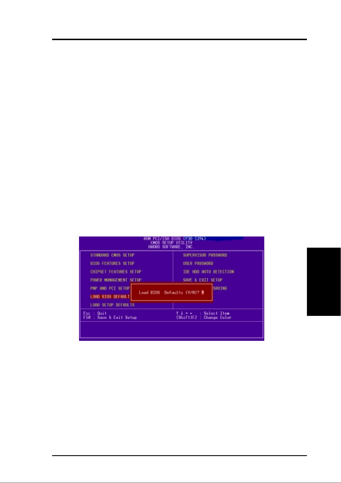
4. BIOS SETUP
4.8 Load BIOS Defaults
This “Load BIOS Defaults” option allows you to load the troubleshooting default
values permanently stored in the BIOS ROM. These default settings are non-optimal and disable all high performance features. To load these default settings, highlight “Load BIOS Defaults” on the main screen and then press <Enter>. The system
displays a confirmation message on the screen. Press <Y> and then <Enter> to confirm. Press <N> and then <Enter> to abort. This feature does not affect the fields on
the Standard CMOS Setup screen.
4.9 Load Setup Defaults
This “Load Setup Defaults” option allows you to load the default values to the system configuration fields. These default values are the optimized configuration settings for the system. To load these default values, highlight “Load Setup Defaults”
on the main screen and then press <Enter>. The system displays a confirmation
message on the screen. Press <Y> and then <Enter> to confirm. Press <N> and then
<Enter> to abort. This feature does not affect the fields on the Standard CMOS
Setup screen.
ASUS P3B-1394 User’s Manual 59
Load Defaults
4. BIOS SETUP
Page 60

4. BIOS SETUP
4.10 Supervisor Password & User Password
These two options set the system passwords. “Supervisor Password” sets a password that will be used to protect the system and the Setup utility; “User Password”
sets a password that will be used exclusively on the system. By default, the system
comes without any passwords. To specify a password, highlight the type you want
and then press <Enter>. A password prompt appears on the screen. T aking note that
the password is case sensitive, and can be up to 8 alphanumeric characters long, type
in your password and then press <Enter>. The system confirms your password by
asking you to type it again. After setting a password, the screen automatically reverts to the main screen.
4. BIOS SETUP
Passwords
To implement password protection, specify in the “Security Option” field of the BIOS
Features Setup screen when the system will prompt for the password. If you want to
disable either password, press <Enter> instead of entering a new password when the
“Enter Password” prompt appears. A message confirms the password has been disabled.
Forgot the password?
If you forgot the password, you can clear the password by erasing the CMOS Real
Time Clock (RTC) RAM. The RAM data containing the password information is
powered by the onboard button cell battery. To erase the RTC RAM: (1) Unplug
your computer, (2) Switch DIP switch 1 to [ON] and then back to [OFF], (3) Turn
ON your computer, (4) Hold down <Delete> during bootup and enter BIOS setup to
re-enter user preferences.
DIP_SW
Clear
®
Normal
(Default)
P3B-1394
P3B-1394 Clear RTC RAM
ASUS P3B-1394 User’s Manual60
ON
1 23456789 10
ON
1 23456789 10
Page 61

4. BIOS SETUP
4.11 IDE HDD Auto Detection
This “IDE HDD Auto Detection” option detects the parameters of an IDE hard disk
drive, and automatically enters them into the Standard CMOS Setup screen.
Up to four IDE drives can be detected, with parameters for each listed inside the
box. To accept the optimal entries, press <Y> or else select from the numbers displayed under the OPTIONS field (2, 1, 3 in this case); to skip to the next drive, press
<N>. If you accept the values, the parameters will appear listed beside the drive
letter on the screen. The process then proceeds to the next drive letter . Pressing <N>
to skip rather than to accept a set of parameters causes the program to enter zeros
after that drive letter.
Remember that if you are using another IDE controller that does not feature Enhanced IDE support for four devices, you can only install two IDE hard disk drives.
Your IDE controller must support the Enhanced IDE features in order to use Drive E
and Drive F. The onboard PCI IDE controller supports Enhanced IDE, with two
connectors for connecting up to four IDE devices. If you want to use another controller that supports four drives, you must disable the onboard IDE controller in the
Chipset Features Setup screen.
When auto-detection is completed, the program automatically enters all entries you
accepted on the field for that drive in the Standard CMOS Setup screen. Skipped
entries are ignored and are not entered in the screen.
If you are auto-detecting a hard disk that supports the LBA mode, three lines will
appear in the parameter box. Choose the line that lists LBA for an LBA drive. Do not
select Large or Normal.
Hard Disk Detect
4. BIOS SETUP
The auto-detection feature can only detect one set of parameters for a particular IDE
hard drive. Some IDE drives can use more than one set. This is not a problem if the
drive is new and empty.
ASUS P3B-1394 User’s Manual 61
Page 62
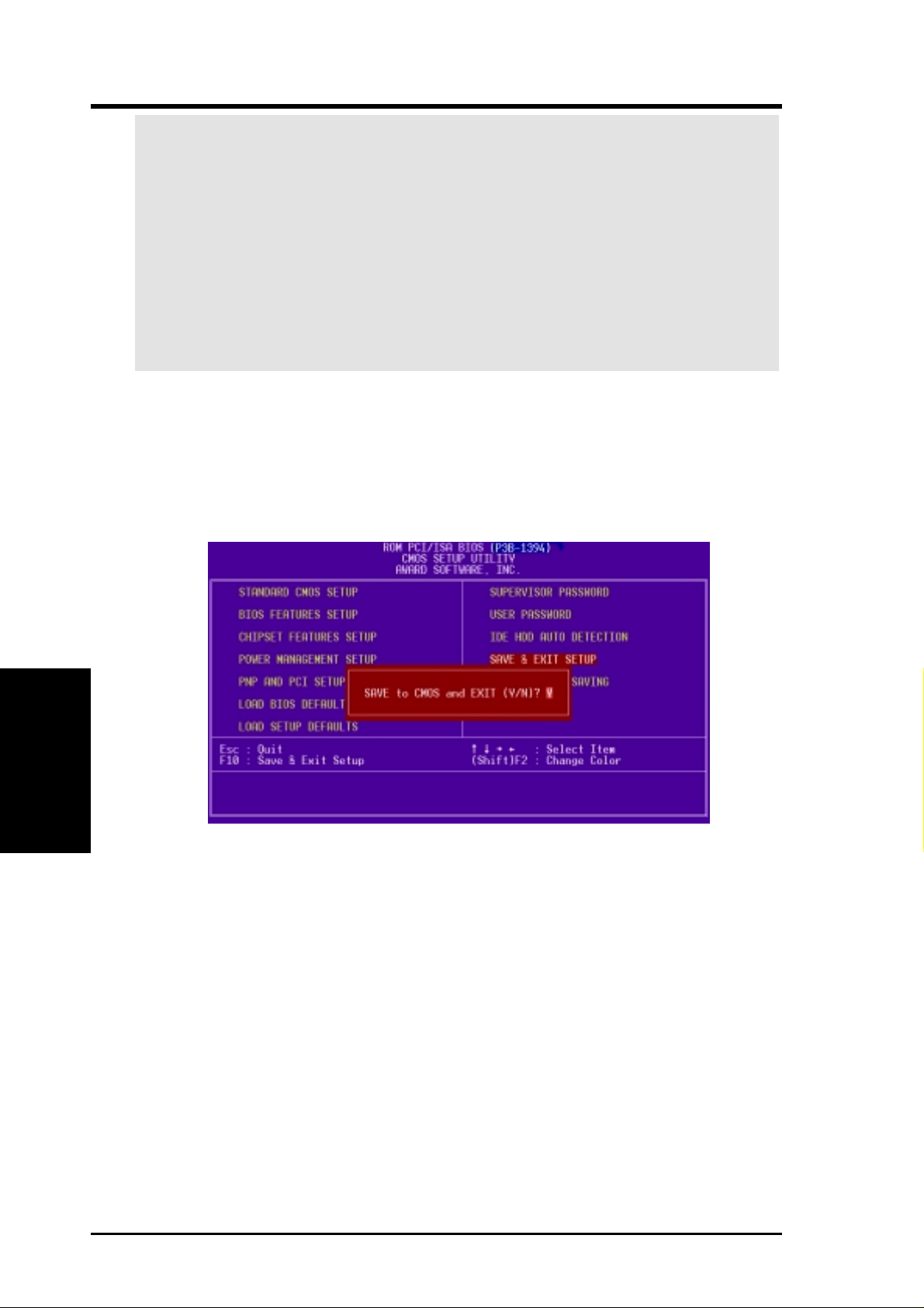
4. BIOS SETUP
IMPORTANT! If your hard disk was already formatted on an older previous sys-
tem, incorrect parameters may be detected. You will need to enter the correct parameters manually or use low-level format if you do not need the data stored on the
hard disk.
If the parameters listed differ from the ones used when the disk was formatted,
the disk will not be readable. If the auto-detected parameters do not match the
ones that should be used for your disk, do not accept them. Press <N> to reject
the presented settings and enter the correct ones manually from the Standard
CMOS Setup screen.
4.12 Save & Exit Setup
Select this option to save into the CMOS memory all modifications you specified
during the current session. T o save the configuration changes, highlight the “Save &
Exit Setup” option on the main screen, type “Y”, and then press <Enter>.
4. BIOS SETUP
Save & Exit
4.13 Exit Without Saving
Select this option to exit the Setup utility without saving the modifications you specify
during the current session. To exit without saving, highlight the “Exit Without Saving” option on the main screen and then press <Enter>.
ASUS P3B-1394 User’s Manual62
Page 63

5. SOFTWARE SETUP
5.1 Operating Systems
You should always use the latest operating system and updates when using new
hardware to ensure full compliancy. For Windows 95, you must use OSR 2.0 or
later. For Windows NT 4.0, you must use Service Pack 3.0 or later.
5.2 Starting Windows For the First Time
Power ON your system and insert your ASUS support CD into your CD-ROM drive.
When you start Windows for the first time after the installation of your motherboard, Windows will detect all plug-and-play devices. You can either follow the
Add New Hardware W izard to install the device drivers or click Cancel and follow
the instructions later in this section.
Install Audio Device Driver
(1) Click here.
(3) Click here.
(5) Browse to
E:\Audio\A3D\Win9x
and then click here.
(2) Click here.
(4) Click here and
then click Next.
Windows 98
5. S/W SETUP
(6) Click here.
ASUS P3B-1394 User’s Manual
63
Page 64
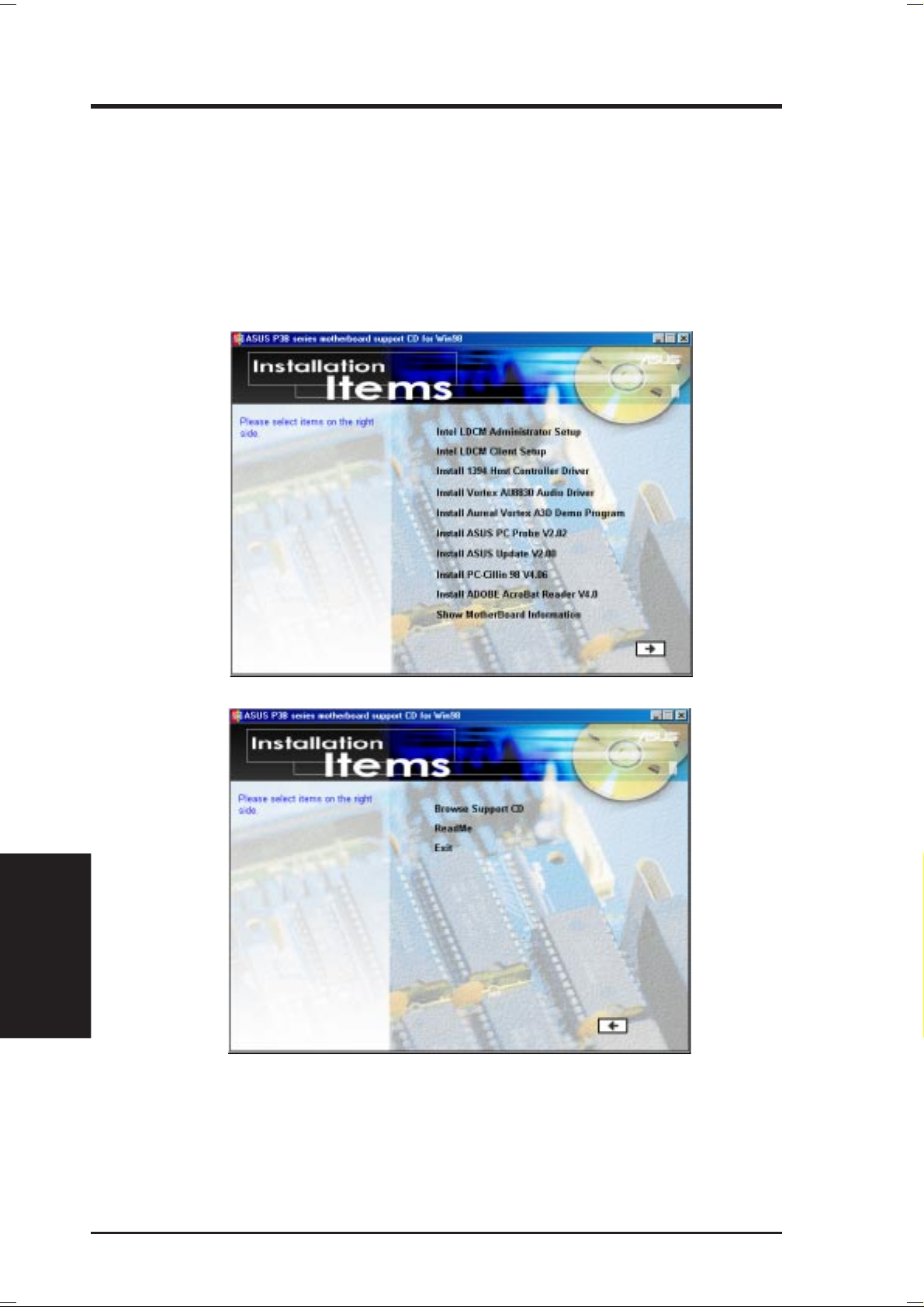
5. SOFTWARE SETUP
5.3 P3B-1394 Support CD
NOTE: The support CD contents are subject to change at any time without notice.
To begin using your support CD disc, just insert it into your CD-ROM drive and the support
CD installation menu should appear. If the menu does not appear, double-click or run
E:\ASSETUP.EXE (assuming that your CD-ROM drive is drive E:).
5.3.1 Installation Menu
5. S/W SETUP
Windows 98
64
ASUS P3B-1394 User’s Manual
Page 65

5. SOFTWARE SETUP
• Intel LDCM Administrator Setup: Installs software to monitor PC systems on
the network within the same bridge address with the Client software installed.
The administrator should install both Client and Administrator Software.
• Intel LDCM Client Setup: Installs software to monitor PC systems on the lo-
cal system. The LANDesk Client Manager must be installed in order to use the
hardware manager features.
• Install 1394 Host Controller Driver: Installs the driver for the onboard 1394
host controller.
• Install V ortex AU8830 Audio Driver: Installs the audio driver for the onboard
audio chipset.
• Install Vortex A3D Demo Program: Installs the A3D demo program.
• Install ASUS PC Pr obe Vx.xx: Installs a simple utility to monitor your computer’s
fan, temperature, and voltages.
• Install ASUS Update Vx.xx: Installs a program to help you update your BIOS
or download a BIOS image file.
• Install PC-Cillin 98 Vx.xx: Installs the PC-cillin virus protection software. View
the online help for more information.
• Install ADOBE AcroBat Reader Vx.x: Installs the Adobe Acrobat Reader soft-
ware necessary to view user’s manuals saved in PDF format. Updated or other
language versions of this motherboard's manual is available in PDF format at
any of our web sites.
• Show Motherboard Information: Allows you to view information about your
motherboard, such as product name, BIOS version, and CPU.
• Browse Support CD: Allows you to view the contents of the CD.
• ReadMe: Displays the filelist for the included support software.
• Exit: Exits the CD installation menu. (Click RIGHT ARROW on the lower-
right corner of the main menu.
Additonal CD Contents: DMI Configuration Utility in the DMI folder, Flash BIOS
writer in the AFLASH folder, IDE Bus Master driver for improved performance
under Windows NT in the BUSMASTR folder, USB patch to fix problems when
using the USB driver under Windows 95 OSR 2.1 in the USBPATCH folder.
NOTE: The screen displays in this and the following section may not reflect exactly
the screen contents displayed on your screen.
Windows 98
5. S/W SETUP
ASUS P3B-1394 User’s Manual
65
Page 66

5. SOFTWARE SETUP
5.4 Intel LDCM Administrator Setup
Insert the Support CD that came with your motherboard into your CD-ROM drive
or double-click the CD drive icon in My Computer to bring up the setup screen.
NOTE: Intel LDCM will not run if another hardware monitoring utility is installed.
To uninstall any program, see 5.11 Uninstalling Programs.
(1) Click here.
(2) Click here.
5. S/W SETUP
Windows 98
(3) Click here.
(5) Click here.
(4) Click here.
(6) Click here and then
click Finish to restart.
66
ASUS P3B-1394 User’s Manual
Page 67
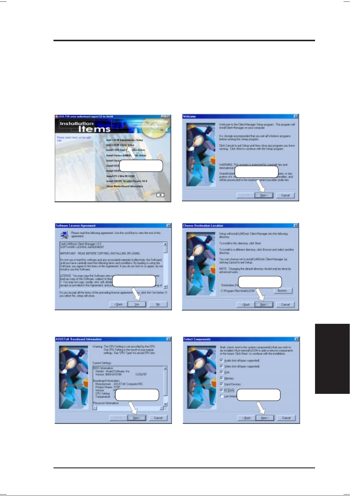
5. SOFTWARE SETUP
5.5 Intel LDCM Client Setup
Insert the Support CD that came with your motherboard into your CD-ROM drive
or double-click the CD drive icon in My Computer to bring up the setup screen.
NOTE: Intel LDCM will not run if another hardware monitoring utility is installed.
To uninstall any program, see 5.11 Uninstalling Programs.
(1) Click here.
(2) Click here.
(3) Click here.
(5) Click here. (6) Click here.
(4) Click here.
Windows 98
5. S/W SETUP
ASUS P3B-1394 User’s Manual
67
Page 68

5. SOFTWARE SETUP
(7) Click here.
(9) Click here.
(8) Click here.
(10) Click here.
5. S/W SETUP
Windows 98
68
(11) Click here and then
click Finish to restart.
ASUS P3B-1394 User’s Manual
Page 69
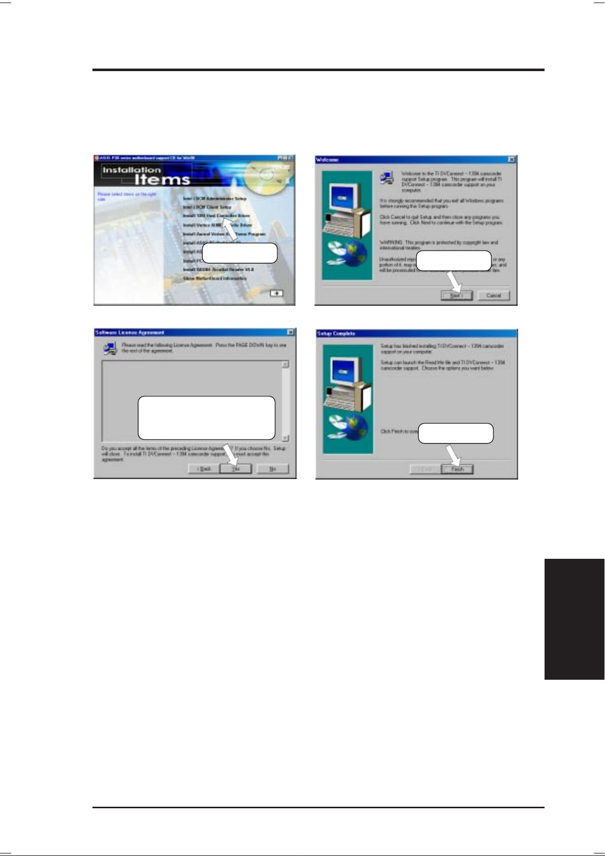
5. SOFTWARE SETUP
5.6 Install 1394 Host Controller Driver
Insert the Support CD that came with your motherboard into your CD-ROM drive
or double-click the CD drive icon in My Computer to bring up the setup screen.
(1) Click here.
(3) Click here only after you
have read the license
agreement.
(2) Click here.
(4) Click here.
ASUS P3B-1394 User’s Manual
Windows 98
5. S/W SETUP
69
Page 70

5. SOFTWARE SETUP
5.7 Install ASUS PC Probe Vx.xx
Insert the Support CD that came with your motherboard into your CD-ROM drive
or double-click the CD drive icon in My Computer to bring up the setup screen.
NOTE: ASUS PC Probe will not run if another hardware monitoring utility is installed. To uninstall any program, see 5.11 Uninstalling Programs.
(2) Click here.
(1) Click here.
5. S/W SETUP
Windows 98
(3) Click here.
(5) Click here.
(7) Click here.
(4) Click here.
(6) Click here.
(8 ) Click Next and when
the Setup Complete box
appears, click Finish.
70
ASUS P3B-1394 User’s Manual
Page 71

5. SOFTWARE SETUP
5.8 Install ASUS Update Vx.xx
Insert the Support CD that came with your motherboard into your CD-ROM drive
or double-click the CD drive icon in My Computer to bring up the setup screen.
(2) Click here.
(1) Click here.
(3) Click here.
(5) Click here.
(4) Click here.
Windows 98
5. S/W SETUP
ASUS P3B-1394 User’s Manual
71
Page 72

5. SOFTWARE SETUP
5.9 Install PC-Cillin 98 Vx.xx
Insert the Support CD that came with your motherboard into your CD-ROM drive
or double-click the CD drive icon in My Computer to bring up the setup screen.
(2) Click here.
(1) Click here.
5. S/W SETUP
Windows 98
(3) Click here only after you have
read the License Agreement.
(5) Click here.
(4) Setup will proceed with
the installation if no viruses are found. Click
here to start installation.
(6) & (7) Select the preferred features by
clicking the appropriate buttons.
72
(8) Insert a floppy disk and then click
here. Once the Emergency Clean
disk is created, click OK.
(9) Click here and then
click Finish to restart.
ASUS P3B-1394 User’s Manual
Page 73

5. SOFTWARE SETUP
5.10 Install ADOBE AcroBat Reader Vx.x
Insert the Support CD that came with your motherboard into your CD-ROM drive
or double-click the CD drive icon in My Computer to bring up the setup screen.
(1) Click here.
(2) Click here.
(3) Click here only after you have
read the License Agreement.
(5) Click here and then
click Finish to restart.
(4) Click here.
Windows 98
5. S/W SETUP
ASUS P3B-1394 User’s Manual
73
Page 74

5. SOFTWARE SETUP
5.11 Uninstalling Programs
Add/Remove Programs is a basic component within Windows. You may use this
function if a program does not provide its own uninstallation program.
5. S/W SETUP
Windows 98
(1) Double-click here to open
the Add/Remove Programs
Properties dialog box.
(2) Select the program to
remove and click here.
74
(3) Click here.
ASUS P3B-1394 User’s Manual
Page 75

5. SOFTWARE SETUP
5.12 Ulead VideoStudio 3.0 SE DV
5.12.1 System Requirements
• Pentium II 266MHz recommended for Digital Video (DV).
• For DV device control, you will need an OHCI-compliant IEEE-1394 controller and a DV camcorder
• A hard disk drive with a sustained transfer rate of at least 3.6MB per second
(SCSI and UltraDMA hard disk drivers are recommended).
• Microsoft Windows 95, Windows 98, or Windows NT 4.0. For DV support,
Windows 98 or Windows 98 SE is required.
• 32MB RAM (64MB recommended)
• 80MB of available hard disk space
• CD-ROM drive
• True color (24 bit) or high color (16 bit) display
• Windows pointing device
• Video for Windows-compatible video capture card (recommended)
• Windows-compatible sound card (recommended)
5.12.2 Ulead Contact Information
North & South America
Ulead Systems, Inc.
970 West 190th Street, Suite 520
Torrance, CA 90502
USA
Tech Support: 1-310-523-9391
FAX: 1-310-523-9399
http://www.ulead.com
e-mail: support@ulead.com
Germany
Ulead Support Center
Am Strühtchen 8
D-56412 Großholbach
Tel: +49-2602-917-329
Fax: +49-2602-917-327
e-mail: uleadger@aol.com
Ulead Systems GmbH
Wolfenbuetteler Str. 33
38102 Braunschweig
Germany
Tel: +49-531-220-7920
Fax: +49-531-220-7999
http://www.ulead.de
e-mail: support@ulead.de
France
Upgrade & Support Center
30 rue du Bailly
93210 Saint Denis La Plaine
France
Tel: +33-1-4946-2346
FAX: +33-1-4946-2349
Support Hot Line: +33-1-4946-2340
http://www.graphics-france.com
e-mail: support@graphics-france.com
All Other Countries
Ulead Systems, Inc
10F, No. 45
Tung Hsing Rd.
T aipei, Taiwan
Tel: 886-2-2764-8599
FAX: 886-2-2764-9599
FAXBack Hotline:
+886-2-87871748
+886-2-87871749
http://www.ulead.com
e-mail: support@ulead.com.tw
Windows 98
5. S/W SETUP
ASUS P3B-1394 User’s Manual
75
Page 76
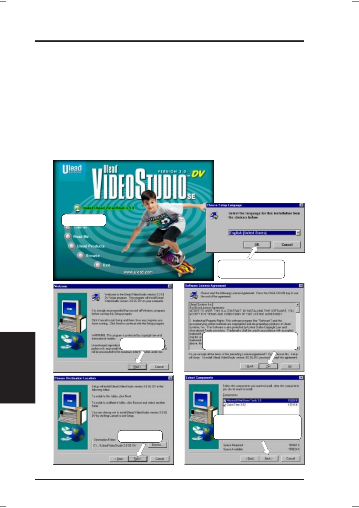
5. SOFTWARE SETUP
5.12.3 Installation Procedure
Insert the Ulead VideoStudio CD into your CD-ROM drive. Windows may automatically run the setup utility or you can use Windows Explorer to browse for, and
then manually run, SETUP.EXE. Click Install Ulead V ideoStudio 3.0 to install the
program as well as the necessary drivers. It is recommended that you install the
selected drivers, as they will optimize the way Ulead VideoStudio works with your
system’s hardware. The unselected drivers are optional. You can choose to install
them at the same time or at a later date by using the Install Drivers option.
NOTE: Read the license agreement carefully before continuing with the installation process. When the installation is complete, please take a moment to go on-line
and instantly register your new software.
5. S/W SETUP
Windows 98
(1) Click here.
(3) Click here.
(2) Select a language
and then click here.
(4) Click here only after you have
read the license agreement.
76
(6) Click here and then follow
the online instructions to
(5) Click here.
finish the installation.
ASUS P3B-1394 User’s Manual
Page 77

6. SOFTWARE REFERENCE
6.1 Intel LANDesk Client Manager
With the growth of the computer industry, computer systems have become more
complex and difficult to manage. Intel LANDesk Client Manager is a computer
management application that simplifies many aspects of managing a computer and
assists in troubleshooting common computer problems.
Intel LDCM
Use Client Manager to:
• Review system inventory
• View DMI-compliant component information
• Backup and restore system files
• Troubleshoot
• Monitor your computer’s health
• Receive notifications for system events
Client Manager has been implemented in two different ways:
The client version enables you to view information and manage alerts for a local
computer. This version does not permit you to select remote computers, transfer
files, or reboot other computers.
The first time you run Client Manager, it searches your network for other computers
running Client Manager . Client Manager creates a list of the computers it finds and
saves the list to the Windows registry. From this point on, when you run Client
Manager or open the Select Computer dialog box, Client Manager checks to see if
these computers (listed in the registry) are available and healthy.
6. S/W REFERENCE
6.1.1 Main Client Manager Window
ASUS P3B-1394 User’s Manual 77
Page 78

6. S/W REFERENCE
6.1.2 Using the Taskbar icons
Intel LDCM
Toolbar Descriptions
6. SOFTWARE REFERENCE
Opens the Select Computer dialog box
Opens the Export dialog box to export the
inventory to a file
Exports the inventory to the clipboard
Opens the notification log
Opens the global notification log
Opens the remote access log
Opens the Configure Notifications dialog
box
Opens the Configure Global Notifications
dialog box
File | Select Computer
File | Export
File | Export to clipboard
View | Notification Log
V iew | Global Notification Log
View | Remote Access Log
T ools | Configure Notifications
Tools | Configure Global
Opens the File Transfer dialog box
Reboots the computer
Opens the DMI Explorer
Opens the Set Access Rights dialog box
Tools | Transfer Files
Tools | Reboot
Tools | DMI Explorer
Tools | Set Access Rights
ASUS P3B-1394 User’s Manual78
Page 79

6. SOFTWARE REFERENCE
6.1.3 Using the Select Computer Dialog Box
Discovers new computers on the network
Intel LDCM
6. S/W REFERENCE
Refreshes the health of known computers
Removes a computer from the list of discovered computers
Wakes up a sleeping computer
Shows all discovered computers
Shows only available computers
Shows only unhealthy computers
Shows a simple list view
Shows a detailed list view
ASUS P3B-1394 User’s Manual 79
Page 80

6. S/W REFERENCE
6.1.4 To select a computer
Intel LDCM
1. From the main Client Manager window, click File | Select Computer.
2. In the Select Computer dialog box, click the computer you want to view.
3. Click the Select button.
6.1.5 To discover new computers
• In the Select Computer dialog box, click the Discover button on the toolbar or
press <Shift>+<F5>.
TIP: Use the Discover button each time you add a computer to the network,
change a computer’s network adapter , or upgrade a computer to a newer version
Client Manager.
6.1.6 To refresh PC health
• In the Select Computer dialog box, click the Refresh Known Computers but-
ton on the toolbar or press <F5>.
6. SOFTWARE REFERENCE
TIP: PC health does not automatically update as changes occur . For example, if
a computer’s health changes while you are displaying the Select Computer dialog box, you need to refresh the list in order to view the correct PC health.
6.1.7 To remove a computer from the list
1. In the Select Computer dialog box, click the computer name you want to remove.
2. Click the Remove Computer button on the toolbar or press Delete.
3. At the prompt, click the Yes button.
TIP: Perform this task each time you remove a computer from the network, since the
name of that computer is not automatically removed from this list.
6.1.8 To wake up a computer
1. In the Select Computer dialog box, click the computer name you want to wake
up. You can also <Shift>+click to select a continuous group of computers or
<Ctrl>+click to select individual computers in the list.
TIP: You can only attempt to wake up computers that have a status of Unavailable or Wakeable. If the Select Computer dialog box does not display any computers with a status of Unavailable or Wakeable and you suspect it should, the
list view may be filtered to display only unhealthy or available computers. You
may need to change your list view to display all computers.
2. Click the Wake Up Computer button on the toolbar to wake up the selected
computer(s) or press <Alt>+<W>.
ASUS P3B-1394 User’s Manual80
Page 81

6. SOFTWARE REFERENCE
After you attempt to wake up a computer, the status of that computer changes in the
list view to a Wake Pending status. If the attempt to wake up a computer is successful, the Wake Pending status changes to a status reflecting the computer’s health
(such as Normal, Warning, or Critical). If the computer does not wake up after five
minutes, a message box appears stating possible reasons why the computer did not
respond. (For example, the computer may be disabled or may not support Wake-OnLAN.) After clicking OK, the Wake Pending status reverts to its original status of
Unavailable or Wakeable.
NOTE: You computer must have a Wake-On-LAN network adapter to support this
feature. Some computers that support the Wake-On-LAN technology may have remote wakeup disabled in the BIOS by default. Before Client Manager can wake up
a remote computer, you will need to enable this option in the BIOS configuration of
each remote computer.
6.1.9 Displaying the Properties of a Client Computer
You can display the properties of any discovered client computer even if you cannot
otherwise access the computer because of access limitations or Unavailable status.
If you display the properties of an unavailable computer, the properties are read
from a database in the Windows registry on your computer. Since the Operating
System information is not stored in this same database, that information is not available for a computer with a status of Unavailable. Remember that some items may
not be current if the properties have changed while the computer was off the network.
Intel LDCM
6. S/W REFERENCE
ASUS P3B-1394 User’s Manual 81
Page 82

6. S/W REFERENCE
6.1.10 Understanding the Computer Status Icons
Intel LDCM
When you open the Select Computer dialog box, each computer in the list displays
an icon indicating the current status of that computer . The table below describes the
seven states a computer may be in.
6. SOFTWARE REFERENCE
Unavailable The computer is currently in a powered-down state.
Wakeable The computer is currently in a powered-down state but
supports Remote Wakeup technology.
W ake Pending A temporary status (not to exceed five minutes) while
Client Manager attempts to wake up a computer . (A computer that is in the process of booting without having
received a wakeup instruction is listed as Unavailable,
not Wake Pending.)
Normal The computer is operating within normal tolerances.
Warning A computer that has exceeded a warning tolerance level.
For example, the PC Health indicator can be configured
to display a warning icon if a hard disk is running low
on space.
Critical A computer that has exceeded a critical tolerance level.
For example, if the hard disk is running critically low
on available space, the PC Health indicator displays a
critical icon.
Unknown A computer that is powered on, but the health status (Nor-
mal, Warning, or Critical) is not known.
Normal (Mobile) A computer that includes support for mobile PC fea-
tures, such as mobile battery . Mobile computers display
the same array of health icons (above) used for nonmobile computers.
ASUS P3B-1394 User’s Manual82
Page 83

6. SOFTWARE REFERENCE
6.2 ASUS PC Probe
ASUS PC Probe is a convenient utility to continuously monitor your computer system’s vital components, such as fan rotations, voltages, and temperatures. It also has a utility that lets you review useful information about
your computer, such as hard disk space, memory usage, and CPU type, CPU
speed, and internal/external frequencies through the DMI Explorer.
6.2.1 Starting ASUS PC Probe
When ASUS PC Probe starts, a splash screen appears allowing you to select
whether to show the screen again when you open PC Probe or not. To bypass this startup screen, clear the Show up in next execution check box.
ASUS PC Probe
6. S/W REFERENCE
To open ASUS PC Probe, click the Windows Start button, point to Programs, and then ASUS Utility, and then click Probe Vx.xx.
The PC Probe icon
that ASUS PC Probe is running. Clicking the icon will allow you to see the
status of your PC.
will appear on the taskbar’s system tray indicating
ASUS P3B-1394 User’s Manual 83
Page 84

6. S/W REFERENCE
ASUS PC Probe
6.2.2 Using ASUS PC Probe
Monitoring
Monitor Summary
Shows a summary of the items being
monitored.
Temperature Monitor
Shows the PC’s temperature.
(Move the slider up to increase the
threshold level or down to decrease
6. SOFTWARE REFERENCE
Temperature Warning
threshold adjustment
the threshold level)
Fan Monitor
Shows the PC’s fan rotation.
Fan Warning
threshold adjustment
(Move the slider up to increase the
threshold level or down to decrease
the threshold level)
Voltage Monitor
Shows the PC’s voltages.
ASUS P3B-1394 User’s Manual84
Page 85

6. SOFTWARE REFERENCE
Settings
Lets you set threshold levels and polling
intervals or refresh times of the PC’ s temperature, fan rotation, and voltages.
History
Lets you record the monitoring activity
of a certain component of your PC by
date, time, and target history.
ASUS PC Probe
6. S/W REFERENCE
Information
Hard Drives
Shows the used and free space of the PC’ s
hard disk drives and the file allocation
table or file system used.
Memory
Shows the PC’s memory load, memory
usage, and paging file usage.
ASUS P3B-1394 User’s Manual 85
Page 86

6. SOFTWARE REFERENCE
6. S/W REFERENCE
ASUS PC Probe
Device Summary
Shows a summary of devices in your PC.
DMI Explorer
Shows information pertinent to the PC,
such as CPU type, CPU speed, and internal/external frequencies, and memory
size.
Utility
Lets you run programs outside of the
ASUS Probe modules. T o run a program,
click Execute Program. NOTE: This
feature is currently unavailable.
ASUS P3B-1394 User’s Manual86
Page 87

6. SOFTWARE REFERENCE
6.2.3 ASUS PC Probe Task Bar Icon
Right clicking the PC Probe
icon will bring up a menu to
open or exit ASUS PC Probe
and pause or resume all system monitoring.
When the ASUS PC Probe
senses a problem with your
PC, portions of the ASUS PC
Probe icon changes to red, the
PC speaker beeps, and the
ASUS PC Probe monitor is displayed.
ASUS PC Probe
6. S/W REFERENCE
ASUS P3B-1394 User’s Manual 87
Page 88

6. SOFTWARE REFERENCE
6. S/W REFERENCE
(This page was intentionally left blank.)
ASUS P3B-1394 User’s Manual88
Page 89

6. SOFTWARE REFERENCE
6.3 Ulead VideoStudio 3.0
Ulead V ideoStudio 3.0 is a powerful tool for making movies on your computer. The
easiest to use and most trouble free video editing software available on the market
today , Ulead V ideoStudio walks you through the process of editing with frame accuracy, adding transition effects, creating animated titles, and recording CD quality
audio tracks. Just follow along the step by step path to video perfection.
Ulead V ideoStudio is two programs in one: V ideo Wizard and Ulead V ideoStudio.
Both work together seamlessly and each is well suited to a particular task. Both can
be run by selecting the programs from the Windows Start menu.
Ulead VideoStudio
6. S/W REFERENCE
Ulead V ideoStudio also has a special Task Guide Help to lead you through each step
and an extensive on-line help, which you can access by pressing F1 on your keyboard while the program is running. You can also find specific information about an
item by moving the cursor over it in the program and pressing F1.
89ASUS P3B-1394 User’s Manual
Page 90
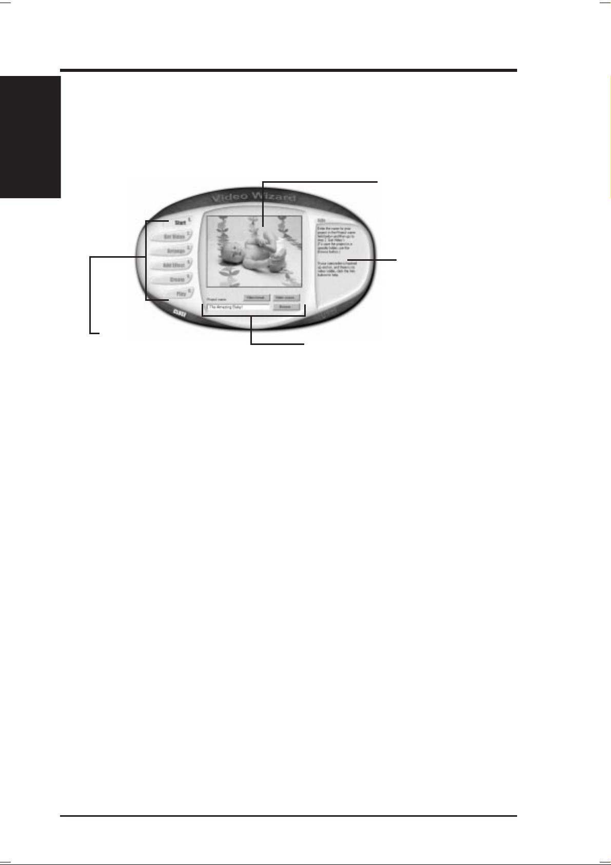
6. S/W REFERENCE
Ulead VideoStudio
6.3.1 Video Wizard
V ideo W izard is a simplified video editor and is fully capable of creating completed
movies. It is also an excellent tool for setting up more sophisticated projects that can
be polished up in Ulead VideoStudio.
6. SOFTWARE REFERENCE
Preview window
Displays the output from
your video source or a
preview of the video files in
your movie.
Step guide
Contains information,
help, and advice to
guide you through a
particular step.
Step buttons
Click to move through the
process of creating a
movie.
Editing tools
Use these buttons, controls,
and text boxes to creatively
produce your movie.
NOTE: Once your video source is connected to your computer, its output should
immediately be visible in the Preview window. If it is not, please refer to your
capture card’s documentation to make sure it is correctly installed and that your
camcorder is properly connected.
When you are ready to go, enter a name for a new project and then click the Get
Video button to move on to the next step. As you complete a procedure, click the
next Step button to move to the next section. Continue through all of the steps to
create a finished movie, ready for viewing. In addition to the new movie, a special
Project file (*.VSP) has also been created, ready to edit further in Ulead VideoStudio.
90 ASUS P3B-1394 User’s Manual
Page 91

6. SOFTWARE REFERENCE
6.3.2 Ulead VideoStudio
Video Wizard and Ulead VideoStudio both follow a step-by-step organization. By
working through the steps, listed from left to right across the Step menu at the top of
the program, you can quickly create fantastic home videos.
Library
Contains all of your
media files, transitions,
and titles.
Step menu
Click the name of a step to
work on a specific aspect of
your movie.
Options panel
Contains all of the editing
tools. The controls change
depending on the step you are
working on.
Preview window
Displays video files or
your camcorder’s output.
Ulead VideoStudio
6. S/W REFERENCE
Trim bar
Use the two handles on
either side of this tool to
quickly edit your clips.
Movie tracks
Shows the four separate
tracks of your movie:
Video, Title, Voice, and
Music.
Timeline/Storyboard
Gives you an overview of
your story at a glance.
Like a professional production, your movie is composed of a number of different
parts. These parts are organized into a project file that is put together visually on the
Timeline at the bottom of the program. Using common Windows techniques, like
drag and drop, you can creatively control your video with ease and precision. When
you are finished editing, you can create, or render, a master copy of your new movie.
91ASUS P3B-1394 User’s Manual
Page 92

6. S/W REFERENCE
Ulead VideoStudio
Step by Step
Here’s a brief walkthrough of Ulead V ideoStudio. Just click the Step menu at the top
of the program interface to move to a particular section.
6. SOFTWARE REFERENCE
1. Start
Create a new project or open an existing
one with the controls in the Options
panel.
2. Capture
Click the Capture button to begin. When
your video source is hooked up correctly,
the output should be visible in the
preview window.
3. Storyboard
Drag and drop clips to the Timeline and
use the Trim bar to make precise edits.
Arrange the sequence of the scenes in
your movie to create a coherent story.
4. Effects
Place cool transition effects between your
clips to give your production a professional touch. Drag and drop operations
mean that nothing could be easier or
more fun.
5. Title
Type opening credits, closing credits,
captions, and titles over your video. Any
True Type font on your computer of any
color style and size can be used. Animated,
scrolling, and fading titles are a click
away.
6. Voice
Give your movie additional clarity by
recording a voiceover narration.
7. Music
Set the mood and add ambiance by using
background music from your favorite CDs.
8. Finish
Create a new movie from your project with
one click. There are a number of exciting
things you can do with the finished
product:
* Watch it on your computer.
* Post it to your Web site.
* Put the movie on a CD-ROM.
* Record it back to video tape.
* Send it by e-mail.
* Create a multimedia greeting card.
92 ASUS P3B-1394 User’s Manual
Page 93

7. APPENDIX
7.1 PCI-L101 Fast Ethernet Card
7. APPENDIX
ASUS LAN Card
LAN Activity
Output Signal
LEDs
RJ45
Wake on LAN
Output Signal
Intel
Chipset
ASUS
Motherboard type
Other
If you are using the ASUS PCI-L101 on an ASUS motherboard, leave the jumper on
its defaut setting of “ASUS.” If you are using another brand of motherboard, set the
jumper to “Other.” Connect the Wake on LAN (WOL) output signal to the
motherboard’ s WOL_CON in order to utilize the wake on LAN feature of the motherboard. Connect the LAN activity output signal (LAN_LED) to the system cabinet’ s
front panel LAN_LED in order to display the LAN data activity.
ASUS P3B-1394 User’s Manual 93
Page 94

7.1.1 Features
• Intel 82558 Ethernet LAN Controller (Fully integrated 10BASE-T/100BASE-TX)
• Wake-On-LAN Remote Control Function Supported
• PCI Bus Master Complies to PCI Local Bus Rev. 2.1 specifications
• Consists of MAC & PHY (10/100Mbps) interfaces
• Complies to IEEE 802.3 10BASE-T and IEEE 802.3u 100BASE-TX interfaces
• Fully supports 10BASE-T & 100BASE-TX operations through a single RJ45 port
ASUS LAN Card
7. APPENDIX
• Supports 32-bit Bus Master Technology / PCI Rev. 2.1
• Enhancements on ACPI & APM
• Adheres to PCI Bus Power Management Interface Rev . 1.0, ACPI Rev . 1.0, and
• IEEE 802.3u auto-negotiation for 10Mbps/100Mbps Network Data Transfer
• Provides LED indicators for monitoring network conditions
• Plug and Play
7. APPENDIX
Device Class Power Management Rev. 1.0
Rates.
7.1.2 Software Driver Support
• NetWare ODI Drivers - Novell Netware 3.x, 4.x, DOS, OS/2 Client
• NDIS 2.01 Drivers - Microsoft LAN Manager, Microsoft Windows 3.11, IBM
LAN Server
• NDIS 3.0 Drivers - Microsoft W indows NT , Microsoft W indows 95, Microsoft
Windows 3.11
7.1.3 Question and Answer
Q: What is Wake-On-LAN ?
A: The Wake-On-LAN feature provides the capability to remotely power on sys-
tems supporting Wake-On-LAN by simply sending a wake-up frame. With this
feature, remotely uploading/downloading data to/from systems during off-peak
hours will be feasible.
Q: What can Wake-On-LAN do for you ?
A: Wake-On-LAN is a remote management tool with advantages that can reduce
system management workload, provide flexibility to the system administrator’s
job, and then of course save you time-consuming efforts and costs.
Q: What components does Wake-On-LAN require to be enable?
A: To enable Wake-On-LAN function, your system requires Ethernet LAN adapter
card that can activate W ake-On-LAN function, a client with W ake-On-LAN capability , and software such as LDCM Rev . 3.10 or up that can trigger wake-up frame.
ASUS P3B-1394 User’s Manual94
Page 95

7. APPENDIX
7.2 S370 Series CPU Cards
The optional ASUS S370 Series CPU Cards allow Slot 1 motherboards to accept
socket 370 processors. The ASUS S370 Series CPU Cards give Slot 1 motherboard
owners an inexpensive way to upgrade their Pentium II computers using lower costing socket 370 processors. Since socket 370 processors are based on the Pentium II
design, the only difference is the connector and the amount of internal cache within
the processor .
The following are pictures of the ASUS S370 Series CPU Cards with black plastic
retainers attached to the edge. The retainer fins are used to hold the ASUS S370
Series CPU Cards in place using the motherboard’s Slot 1 retention mechanisms.
ASUS S370 CPU Card (standard model)
• Better Support with Full Retainer
• Low Cost
CPU Voltage Jumpers
7. APPENDIX
S370 Series CPU Cards
Retainer
Socket 370
Retainer Fin
Slot 1 Compatible Connector
ASUS S370-L CPU Card (for smaller cases)
• Low Profile / Low Cost
• CPU Temperature Sensing
(on supported motherboards)
ASUS S370-D CPU Card (performance model)
• Better Support with Full Retainer
• CPU Temperature Sensing
(on supported motherboards)
• Better Components
ASUS P3B-1394 User’s Manual 95
Page 96

7.2.1 Using the ASUS S370 Series CPU Card
The general procedure for using the ASUS S370 Series CPU Card is as follows:
1. Check the voltage setting for your socket 370 processor using the jumpers on
the card if necessary . For current socket 370 processors, the default setting should
be used. See the reverse side of the ASUS S370 Series CPU Card or this page
for voltage settings.
S370 Series CPU Cards
7. APPENDIX
2. Install the socket 370 processor . Installation of socket 370 processors is exactly
like socket 7 processors. Lift the brown lever to 90° to install the processor and
lower the brown lever to lock the processor.
3. Insert the ASUS S370 Series CPU Card into Slot 1 on the motherboard. The
retainer fin on each side of the ASUS S370 Series CPU Card must catch on the
retention mechanism so that it locks in place.
4. Connect the socket 370 processor’s fan connector to the motherboard.
5. Make sure that no wires or objects come in contact with the fan.
7. APPENDIX
7.2.2 S370 Series CPU Card Jumper Settings
The only set of jumpers on the ASUS S370 Series CPU Card is used for setting the
voltage sent to the CPU. Setting the CPU voltage is not necessary for current socket
370 processors. If required, your socket 370 processor should have its voltage requirement printed on its surface or documentation. If no voltage is indicated or you
are not sure, use the “CPU Def.” setting as shown below.
123
JP5
JP4
JP3
JP2
JP1
1.80Volts
123
JP5
JP4
JP3
JP2
JP1
2.20Volts
JP5
JP4
JP3
JP2
JP1
JP5
JP4
JP3
JP2
JP1
123
1.85Volts
123
2.30Volts
JP5
JP4
JP3
JP2
JP1
JP5
JP4
JP3
JP2
JP1
123
1.90Volts
123
2.40Volts
JP5
JP4
JP3
JP2
JP1
JP5
JP4
JP3
JP2
JP1
123
1.95Volts
123
2.50Volts
JP5
JP4
JP3
JP2
JP1
JP5
JP4
JP3
JP2
JP1
123
2.00Volts
123
2.60Volts
JP5
JP4
JP3
JP2
JP1
JP5
JP4
JP3
JP2
JP1
123
2.05Volts
123
CPU Def.
123
JP5
JP4
JP3
JP2
JP1
2.10Volts
123
JP5
JP4
JP3
JP2
JP1
Reserved
Socket 370 CPU Voltage
W ARNING! Exceeding your socket 370 processor’s required voltage can dam-
age your processor permanently! Make sure that the jumpers are as shown for
“CPU Def.” unless otherwise specified before powering ON your motherboard.
ASUS P3B-1394 User’s Manual96
Page 97

7. APPENDIX7. APPENDIX
7.3 Glossary
AGP (Accelerated Graphics Port)
An interface specification that enables high-performance 3D graphics on mainstream
PCs. AGP offers a higher throughput than PCI by providing the graphics controller
with direct access to system memory.
Bus Bus Frequency Bus Speed
PCI 33MHz 133MB/s
AGP 1X 66MHz 200-300MB/s
AGP 2X 133MHz 528MB/s
AGP 4X 266MHz 1 GB/s
AUTOEXEC.BAT
AUTOEXEC.BAT is a special-purpose file that is automatically executed by DOS
whenever the computer is turned ON or restarted. This file contains important commands that help configure the system to work with certain software and devices.
Windows 95 and later has its own startup files and may not use or may ignore parts
of the AUTOEXEC.BAT file.
Glossary
7. APPENDIX
BIOS (Basic Input/Output System)
BIOS is a set of routines that affect how the computer transfers data between computer components, such as memory, disks, and the display adapter. The BIOS instructions are built into the computer’s read-only memory. BIOS parameters can be
configured by the user through the BIOS Setup program. The BIOS can be updated
using the provided utility to copy a new BIOS file into the EEPROM.
Bit (Binary Digit)
Represents the smallest unit of data used by the computer . A bit can have one of two
values: 0 or 1.
Boot
Boot means to start the computer operating system by loading it into system memory .
When the manual instructs you to “boot” your system (or computer), it means to
turn ON your computer . “Reboot” means to restart your computer . When using W indows 95 or later, selecting “Restart” from “Start | Shut Down...” will reboot your
computer.
Bus Master IDE
PIO (Programmable I/O) IDE requires that the CPU be involved in IDE access and
waiting for mechanical events. Bus master IDE transfers data to/from the memory
without interrupting the CPU. Bus master IDE driver and bus master IDE hard disk
drives are required to support bus master IDE mode.
ASUS P3B-1394 User’s Manual 97
Page 98

7. APPENDIX7. APPENDIX
Byte (Binary Term)
One byte is a group of eight contiguous bits. A byte is used to represent a single
alphanumeric character, punctuation mark, or other symbol.
COM Port
COM is a logical device name used by to designate the computer serial ports. Pointing devices, modems, and infrared modules can be connected to COM ports. Each
COM port is configured to use a different IRQ and address assignment.
7. APPENDIX
Glossary
CPU (Central Processing Unit)
The CPU, sometimes called “Processor,” actually functions as the “brain” of the
computer. It interprets and executes program commands and processes data stored
in memory. Currently, there are socket 370 (for Pentium Celeron-PPGA), socket 7
(for Pentium, AMD, Cyrix, IBM), slot 1 (for Pentium II and III), and slot 2 (for
Xeon) processors.
Device Driver
A device driver is a special set of instructions that allows the computer’s operating system to communicate with devices such as VGA, audio, ethernet, printer , or modem.
DOS (Disk Operating System)
DOS is the foundation on which all other programs and software applications operate, including W indows. DOS is responsible for allocating system resources such as
memory, CPU time, disk space, and access to peripheral devices. For this reason,
DOS constitutes the basic interface between you and your computer.
Endian
Endian is a byte order system used in data transfers. In big-endian architectures, the
lower addresses are most significant. In little-endian architectures, the higher bytes
are most significant. Mainframe computers, such as those by IBM, use a big-endian
architecture. Modern PCs use the little-endian system.
Hardware
Hardware is a general term referring to the physical components of a computer system, including peripherals such as printers, modems, and pointing devices.
IDE (Integrated Drive Electronics)
IDE devices integrate the drive control circuitry directly on the drive itself, eliminating the need for a separate adapter card (in the case for SCSI devices). UltraDMA/
33 IDE devices can achieve up to 33MB/Sec transfer.
LPT Port (Line Printer Port)
Logical device name reserved by DOS for the computer parallel ports. Each LPT
port is configured to use a different IRQ and address assignment.
ASUS P3B-1394 User’s Manual98
Page 99

7. APPENDIX7. APPENDIX
MMX
A set of 57 new instructions based on a technique called Single Instruction, Multiple
Data (SIMD), which is built into the new Intel Pentium PP/MT (P55C) and Pentium
II (Klamath) CPU as well as other x86-compatible microprocessors. The MMX instructions are designed to accelerate multimedia and communications applications,
such as 3D video, 3D sound, video conference.
PCI Bus (Peripheral Component Interconnect Local Bus)
PCI bus is a specification that defines a 32-bit data bus interface. PCI is a standard
widely used by expansion card manufacturers.
Peripherals
Peripherals are devices attached to the computer via I/O ports. Peripheral devices
allow your computer to perform an almost limitless variety of specialized tasks.
POST (Power On Self Test)
When you turn on the computer, it will first run through the POST, a series of software-controlled diagnostic tests. The POST checks system memory, the motherboard circuitry, the display, the keyboard, the diskette drive, and other I/O devices.
Glossary
7. APPENDIX
PS/2 Port
PS/2 ports are based on IBM Micro Channel Architecture. This type of architecture
transfers data through a 16-bit or 32-bit bus. A PS/2 mouse and/or keyboard may be
used on ATX motherboards.
RAID (Redundant Array of Independent Disks)
RAID can be set up to provide mirroring (for fault tolerance), parity (for data guarding), or striping (for data distribution over several drives for increased performance).
A RAID card is required to setup a RAID system.
RAM (Random Access Memory)
There are several different types of RAM such as DRAM (Dynamic RAM), EDO
DRAM (Extended Data Output DRAM), SDRAM (Synchronous DRAM).
ROM (Read Only Memory)
ROM is nonvolatile memory used to store permanent programs (called firmware)
used in certain computer components. Flash ROM (or EEPROM) can be reprogrammed with new programs (or BIOS).
SCSI (Small Computer System Interface)
High speed parallel interface defined by the X3T9.2 committee of the American
National Standards Institute (ANSI) for connecting many peripheral devices.
System Disk
A system disk contains the core file of an operating system and is used to boot up the
operating system.
ASUS P3B-1394 User’s Manual 99
Page 100

7. APPENDIX
Glossary
7. APPENDIX7. APPENDIX
UltraDMA/33
UltraDMA/33 is a new specification to improve IDE transfer rates. Unlike traditional PIO mode, which only uses the rising edge of IDE command signal to transfer
data, the DMA/33 uses both rising edge and falling edge. Hence, the data transfer
rate is double of the PIO mode 4 or DMA mode 2. (16.6MB/s x2 = 33MB/s).
USB (Universal Serial Bus)
A new 4-pin serial peripheral bus that allows plug and play computer peripherals
such as keyboard, mouse, joystick, scanner, printer and modem/ISDN to be automatically configured when they are attached physically without having to install
drivers or reboot. W ith USB, the traditional complex cables from back panel of your
PC can be eliminated.
ASUS P3B-1394 User’s Manual100
 Loading...