

Page 1
Pundit P3-AE5
ASUS PC (Desktop Barebone)
Page 2
E272 8
Firs t E diti o n V1
Nove m b e r 20 0 6
Copyright © 2006 ASUSTeK COMPUTER INC. All Rights Reserved.
No part of this manual, including the products and software described in it, may be reproduced,
transmitted, transcribed, stored in a retrieval system, or translated into any language in any form
or by any means, except documentation kept by the purchaser for backup purposes, without the
express written permission of ASUSTeK COMPUTER INC. (“ASUS”).
Product warranty or service will not be extended if: (1) the product is repaired, modied or
altered, unless such repair, modication of alteration is authorized in writing by ASUS; or (2) the
serial number of the product is defaced or missing.
ASUS PROVIDES THIS MANUAL “AS IS” WITHOUT WARRANTY OF ANY KIND, EITHER EXPRESS
OR IMPLIED, INCLUDING BUT NOT LIMITED TO THE IMPLIED WARRANTIES OR CONDITIONS OF
MERCHANTABILITY OR FITNESS FOR A PARTICULAR PURPOSE. IN NO EVENT SHALL ASUS,
ITS DIRECTORS, OFFICERS, EMPLOYEES OR AGENTS BE LIABLE FOR ANY INDIRECT, SPECIAL,
INCIDENTAL, OR CONSEQUENTIAL DAMAGES (INCLUDING DAMAGES FOR LOSS OF PROFITS, LOSS
OF BUSINESS, LOSS OF USE OR DATA, INTERRUPTION OF BUSINESS AND THE LIKE), EVEN IF ASUS
HAS BEEN ADVISED OF THE POSSIBILITY OF SUCH DAMAGES ARISING FROM ANY DEFECT OR
ERROR IN THIS MANUAL OR PRODUCT.
SPECIFICATIONS AND INFORMATION CONTAINED IN THIS MANUAL ARE FURNISHED FOR
INFORMATIONAL USE ONLY, AND ARE SUBJECT TO CHANGE AT ANY TIME WITHOUT NOTICE, AND
SHOULD NOT BE CONSTRUED AS A COMMITMENT BY ASUS. ASUS ASSUMES NO RESPONSIBILITY
OR LIABILITY FOR ANY ERRORS OR INACCURACIES THAT MAY APPEAR IN THIS MANUAL,
INCLUDING THE PRODUCTS AND SOFTWARE DESCRIBED IN IT.
Products and corporate names appearing in this manual may or may not be registered
trademarks or copyrights of their respective companies, and are used only for identication or
explanation and to the owners’ benet, without intent to infringe.
ii
Page 3
Table of contents
Notices ................................................................................................ vi
Safety information ..............................................................................vii
About this guide .................................................................................viii
System package contents .................................................................... x
Cha p te r 1 : S y ste m I n tro d uc t ion
1.1 Welcome! .............................................................................. 1-2
1.2 Front panel ..........................................................................
1.3 Rear panel .............................................................................
1.4 Internal components .............................................................
Cha p te r 2 : Bas i c I nst a ll a tio n
2.1 Preparation ........................................................................... 2-2
2.2 Before you proceed ..............................................................
2.3 Removing the side cover and front panel assembly .............
2.4 Central Processing Unit (CPU) ..............................................
2.4.1 Overview .................................................................
2.4.2 Installing CPU ..........................................................
2.4.3 Installing the heatsink and fan ................................
2.5 Installing a DIMM ...................................................................
2.5.1 Memory congurations ...........................................
2.5.2 Installing a DDR2 DIMM .........................................
2.5.3 Removing a DDR2 DIMM ........................................
2.6 Expansion slots ...................................................................
2.6.1 Expansion slots .....................................................
2.6.2 Expansion card installation ....................................
2.7 Installing an optical drive ....................................................
2.8 Removing the card reader
2.9 Installing hard disk drives (HDDs) .......................................
2.9.1 Hard disk drive bays ..............................................
2.9.2 SATA hard disk drive installation ..........................
2.9.3 IDE hard disk drive installation ..............................
2.9.4 Uninstalling a hard disk drive ................................
................................................... 2-16
1-2
1-4
1-7
2-2
2-3
2-4
2-4
2-4
2-6
2-8
2-8
2-10
2-10
2-11
2-11
2-11
2-14
2-17
2-17
2-17
2-19
2-19
iii
Page 4
Table of contents
2.10 Replacing the covers ........................................................... 2-20
2.10.1 Replacing the front panel assembly ......................
2.10.2 Replacing the system cover ..................................
2.11 Installing the foot stands .................................................... 2-22
Cha p te r 3 : Sta r ti n g u p
3.1 Installing an operating system .............................................. 3-2
3.2 Powering up ..........................................................................
3.3 Support CD information ........................................................
3.3.1 Running the support CD ..........................................
3.3.2 Drivers menu ...........................................................
3.3.3 Utilities Disk ............................................................
3.3.4 Make Disk menu ......................................................
3.3.5 ASUS Contact information ......................................
Cha p te r 4 : Mot h er b oar d I n for m at i on
4.1 Introduction .......................................................................... 4-2
4.2 Motherboard layout ..............................................................
4.3 Jumpers ................................................................................
4.4 Connectors ...........................................................................
2-20
2-21
3-2
3-3
3-3
3-4
3-5
3-6
3-7
4-2
4-3
4-4
Cha p te r 5 : BIO S S e tup
5.1 Managing and updating your BIOS ........................................ 5-2
5.1.1 Creating a bootable oppy disk ..............................
5.1.2 ASUS EZ Flash utility ...............................................
5.1.3 AFUDOS utility ........................................................
5.1.4 ASUS Update utility ................................................
5.2 BIOS setup program ..............................................................
5.2.1 BIOS menu screen .................................................
5.2.2 Menu bar ...............................................................
5.2.3 Navigation keys .....................................................
5.2.4 Menu items ...........................................................
5.2.5 Sub-menu items ....................................................
5.2.6 Conguration elds ...............................................
5.2.7 Pop-up window ......................................................
5.2.8 Scroll bar ...............................................................
5.2.9 General help ..........................................................
iv
5-2
5-3
5-4
5-6
5-9
5-10
5-10
5-10
5-11
5-11
5-11
5-11
5-13
5-11
Page 5

Table of contents
5.3 Main menu ........................................................................... 5-12
5.3.1 System Time ........................................................
5.3.2 System Date ........................................................
5.3.3 Legacy Diskette A ...............................................
5.3.4
5.3.5 System Information
5.4 Advanced menu ..................................................................
5.4.1 USB conguration .................................................
5.4.2 CPU Conguration .................................................
5.4.3 Chipset ..................................................................
5.4.4 Onboard Devices Conguration .............................
5.4.5 PCI PnP ..................................................................
5.5 Power menu ........................................................................
5.5.1 Suspend Mode ......................................................
5.5.2 ACPI 2.0 Support ..................................................
5.5.3 ACPI APIC Support ................................................
5.5.4 Power Management/APM ......................................
5.5.5 Hardware monitor .................................................
5.6 Boot menu ..........................................................................
5.6.1 Boot Device Priority ..............................................
5.6.2 Boot Settings Conguration .................................
5.6.3 Security .................................................................
5.7 Exit menu ............................................................................
Primary and Secondary IDE Master/Slave ............. 5-13
............................................... 5-14
5-12
5-12
5-12
5-15
5-15
5-16
5-17
5-22
5-22
5-24
5-24
5-24
5-24
5-24
5-26
5-27
5-27
5-28
5-29
5-31
v
Page 6
Notices
Fed er al Co mm un ica ti on s C om mi ssi on S tat em en t
This device complies with Part 15 of the FCC Rules. Operation is subject to
the following two conditions:
•
This device may not cause harmful interference, and
•
This device must accept any interference received including
interference that may cause undesired operation.
This equipment has been tested and found to comply with the limits for a
Class B digital device, pursuant to Part 15 of the FCC Rules. These limits
are designed to provide reasonable protection against harmful interference
in a residential installation. This equipment generates, uses and can radiate
radio frequency energy and, if not installed and used in accordance with
manufacturer’s instructions, may cause harmful interference to radio
communications. However, there is no guarantee that interference will
not occur in a particular installation. If this equipment does cause harmful
interference to radio or television reception, which can be determined by
turning the equipment off and on, the user is encouraged to try to correct
the interference by one or more of the following measures:
•
Reorient or relocate the receiving antenna.
•
Increase the separation between the equipment and receiver.
•
Connect the equipment to an outlet on a circuit different from that to
which the receiver is connected.
WARNING! The use of shielded cables for connection of the monitor to
the graphics card is required to assure compliance with FCC regulations.
Changes or modications to this unit not expressly approved by the
party responsible for compliance could void the user’s authority to
operate this equipment.
Can ad ia n D ep ar tme nt o f C om mu nic at io ns St at eme nt
This digital apparatus does not exceed the Class B limits for radio noise
emissions from digital apparatus set out in the Radio Interference
Regulations of the Canadian Department of Communications.
This class B digital apparatus complies with Canadian ICES-003.
vi
Page 7
Safety information
Ele ct ri cal s af ety
•
To prevent electrical shock hazard, disconnect the power cable from
the electrical outlet before relocating the system.
•
When adding or removing devices to or from the system, ensure that
the power cables for the devices are unplugged before the signal cables
are connected.
•
If the power supply is broken, do not try to fix it by yourself. Contact a
qualified service technician or your retailer.
Ope ra ti on sa fe ty
•
Before installing devices into the system, carefully read all the
documentation that came with the package.
•
Before using the product, make sure all cables are correctly connected
and the power cables are not damaged. If you detect any damage,
contact your dealer immediately.
•
To avoid short circuits, keep paper clips, screws, and staples away from
connectors, slots, sockets and circuitry.
•
Avoid dust, humidity, and temperature extremes. Do not place the
product in any area where it may become wet. Place the product on a
stable surface.
•
If you encounter technical problems with the product, contact a
qualified service technician or your retailer.
Lithium-Ion Battery Warning
CAUTION: Danger of explosion if battery is incorrectly replaced.
Replace only with the same or equivalent type recommended by
the manufacturer. Dispose of used batteries according to the
manufacturer’s instructions.
VORSICHT: Explosionsgetahr bei unsachgemäßen Austausch der
Batterie. Ersatz nur durch denselben oder einem vom Hersteller
empfohlenem ähnljchen Typ. Entsorgung gebrauchter Batterien nach
Angaben des Herstellers.
LASER PRODUCT WARNING
CLA SS 1 LA SE R PRO DU CT
vii
Page 8
About this guide
Aud ie nc e
This guide provides general information and installation instructions about
the ASUS Pundit P3-AE5 barebone system. This guide is intended for
experienced users and integrators with hardware knowledge of personal
computers.
How t hi s g ui de is o rg ani ze d
This guide contains the following parts:
1. C h a pter 1 : Sys t e m int r o d ucti o n
This chapter gives a general description of the ASUS Pundit P3-AE5
barebone system. The chapter lists the system features, including
introduction on the front and rear panel, and internal components.
2. C h a pter 2 : Bas i c inst a l l atio n
This chapter provides step-by-step instructions on how to install
components in the system.
3. C h a pter 3 : Sta r t i ng u p
This chapter helps you power up the system and install drivers and
utilities from the support CD.
4. C h a pter 4 : Mot h e r boar d i nfor m a t ion
This chapter gives information about the motherboard that comes
with the system. This chapter includes the motherboard layout,
jumper settings, and connector locations.
5. C h a pter 5 : BIO S s etup
This chapter tells how to change system settings through the BIOS
Setup menus and describes the BIOS parameters.
viii
Page 9
Con ve nt ion s us ed in t his g ui de
WARNING: Information to prevent injury to yourself when trying
to complete a task.
CAUTION: Information to prevent damage to the components
when trying to complete a task.
IMPORTANT: Instructions that you MUST follow to complete a
task.
NOTE: Tips and additional information to aid in completing a
task.
Whe re t o f in d mor e in for ma ti on
Refer to the following sources for additional information and for product
and software updates.
1. A S U S We b s i tes
The ASUS websites worldwide provide updated information on
ASUS hardware and software products. Refer to the ASUS contact
information.
2. O p t iona l D ocum e n t atio n
Your product package may include optional documentation, such as
warranty yers, that may have been added by your dealer. These
documents are not part of the standard package.
ix
Page 10
System package contents
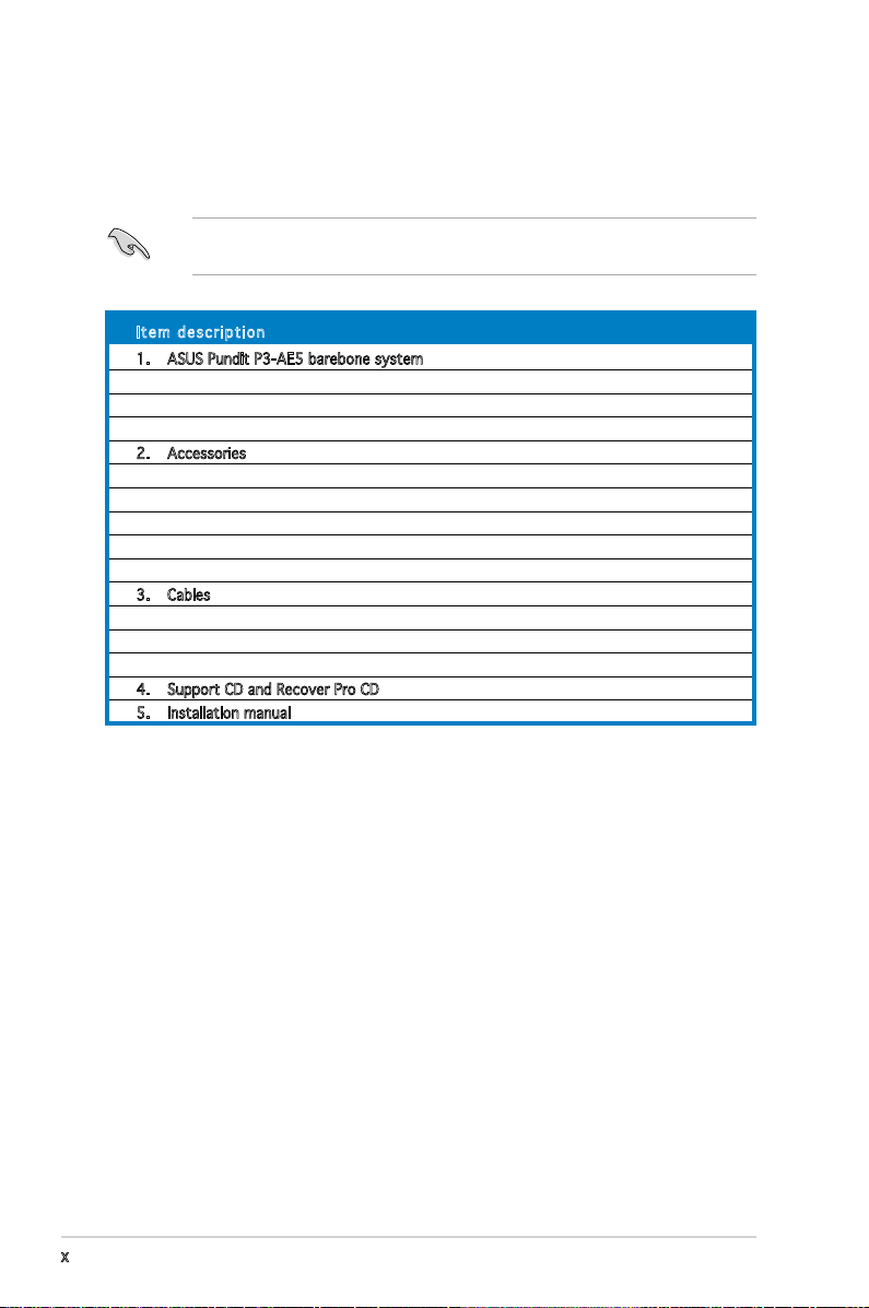
Check your ASUS Pundit P3-AE5 barebone system package for the
following items.
If any of the items is damaged or missing, contact your retailer
immediately.
Ite m d escri p t i on
1. ASUS Pundit P3-AE5 barebone system with
• ASUS motherboard
• 275 W PFC power supply unit
• 6-in-1 storage card reader
2. Accessories
• Foot stand and screw (1 pair) for vertical placement
• Rubber stand (x4) for horizontal placement
• Hard disk drive screw (x8)
• Optical drive screw (x2)
• Rubber washer (x8)
3. Cables
• AC power cable
• Serial ATA signal cable (x2)
• IDE cable (x1)
4. Support CD and Recover Pro CD
5. Installation manual
x
Page 11
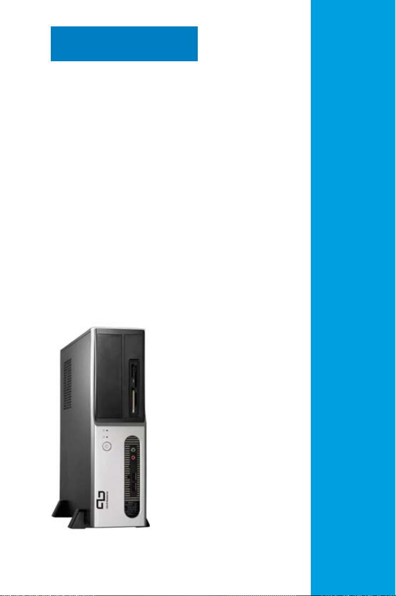
Chapter 1
This chapter gives a general
description of the ASUS
Pundit P3-AE5 Barebone System.
The chapter lists the system
features including introduction
on the front and rear panel, and
internal components.
System introduction
Page 12
1.1 Welcome!
Thank you for choosing the ASUS Pundit P3-AE5!
The ASUS Pundit P3-AE5 is an all-in-one barebone system with a versatile
home entertainment feature.
The system comes in a stylish mini-tower casing and powered by the ASUS
motherboard that supports the AMD Athlon™ FX/AMD Athlon™ 64 X2/AMD
Athlon™ 64/AMD Sempron™ processor in a 940-pin AM2 socket.
The system supports up to 2 GB of system memory using DDR2-667/533
DIMMs. VIA integrated graphics, Serial ATA, USB 2.0, and 8-channel audio
feature the system and take you ahead in the world of power computing.
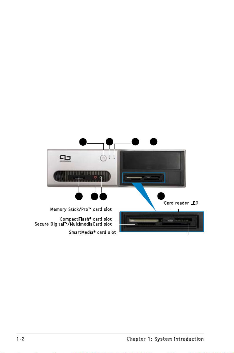
1.2 Front panel
4
5
6
7
Mem o r y Stic k / P ro™ c a r d slot
Sec u r e Digi t a l ™ /Mul t i m e diaC a r d slot
Com p a c tFlas h® ca r d slot
Sma r t M edia® ca r d slot
3
12
8
Car d r eader L E D
1-2 Chapter 1: System introduction
Page 13
1. 5.25-inch drive bay cover. This bay is for IDE optical drives.
2. HDD LED. This LED lights up when data is read from or written to the
hard disk drive.
3. Power LED.
4. Power button. Press this button to turn the system on.
5. USB 2.0 ports. These Universal Serial Bus 2.0 (USB 2.0) ports are
available for connecting USB 2.0 devices such as a mouse, printer,
scanner, camera, PDA, and others.
6. Microphone port. This Mic (pink) port connects a microphone.
7. Headphone port. This Line In (green) port connects a headphone with
a stereo mini-plug.
8. 6-in-1 storage card reader.
Memory Stick/Pro™ card slot.
CompactFlash® card slot.
Secure Digital™/MultimediaCard slot.
SmartMedia® card slot.
1-3ASUS Pundit P3-AE5
Page 14
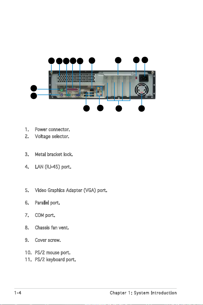
1.3 Rear panel
The system rear panel includes the power connector and several I/O ports
that allow convenient connection of devices.
2
3
14
10
11
9
6
78
4
5
13
12
1. Power connector. This connector is for the power cable and plug.
2. Voltage selector. This switch allows you to adjust the system input
voltage according to the voltage supply in your area. See the section
“Voltage selector” on page 1-6 before adjusting this switch.
3. Metal bracket lock. Remove the metal bracket lock on the rear panel
when installing expansion cards.
4. LAN (RJ-45) port. Supported by Realtek® Gigabit LAN controller,
this port allows Gigabit connection to a Local Area Network (LAN)
through a network hub. Refer to the table below for the LAN port LED
indications.
5. Video Graphics Adapter (VGA) port. This port is for a VGA monitor or
other VGA-compatible devices.
6. Parallel port. This 25-pin port connects a parallel printer, a scanner, or
other devices.
7. COM port. This 15-pin port is for a VGA monitor or other VGAcompatible devices.
8. Chassis fan vent. This vent is for the fan that provides ventilation
inside the system chassis.
9. Cover screw. Remove the cover screws on the rear panel when
installing expansion cards.
10. PS/2 mouse port. This port is for a PS/2 mouse.
11. PS/2 keyboard port. This port is for a PS/2 keyboard.
1
15
1-4 Chapter 1: System introduction
Page 15
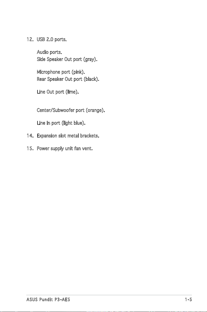
12. USB 2.0 ports. These 4-pin Universal Serial Bus (USB) ports are
available for connecting USB 2.0 devices.
Audio ports.
13.
Side Speaker Out port (gray). This port connects the side speakers in
an 8-channel audio conguration.
Microphone port (pink). This port connects a microphone.
Rear Speaker Out port (black). This port connects the rear speakers in
a 4-channel, 6-channel, or 8-channel audio conguration.
Line Out port (lime). This port connects a headphone or a speaker.
In 4-channel and 6-channel conguration, the function of this port
becomes Front Speaker Out.
Center/Subwoofer port (orange). This port connects the center/
subwoofer speakers.
Line In port (light blue). This port connects the tape, CD, DVD player,
or other audio sources.
14. Expansion slot metal brackets. Remove these brackets when installing
expansion cards.
15. Power supply unit fan vent. This vent is for the PSU fan that provides
ventilation inside the power supply unit.
1-5ASUS Pundit P3-AE5
Page 16
Refer to the audio conguration table below for the function of the audio
ports in 2, 4, 6, or 8-channel conguration.
Audio 2, 4, 6, or 8-channel conguration
Port Headset
2-channel
Light Blue Line In Line In Line In Line In
Lime Line Out Front Speaker Out Front Speaker Out Front Speaker Out
Pink Mic In Mic In Mic In Mic In
Orange – – Center/Subwoofer Center/Subwoofer
Black – Rear Speaker Out Rear Speaker Out Rear Speaker Out
Gray – – – Side Speaker Out
4-channel 6-channel 8-channel
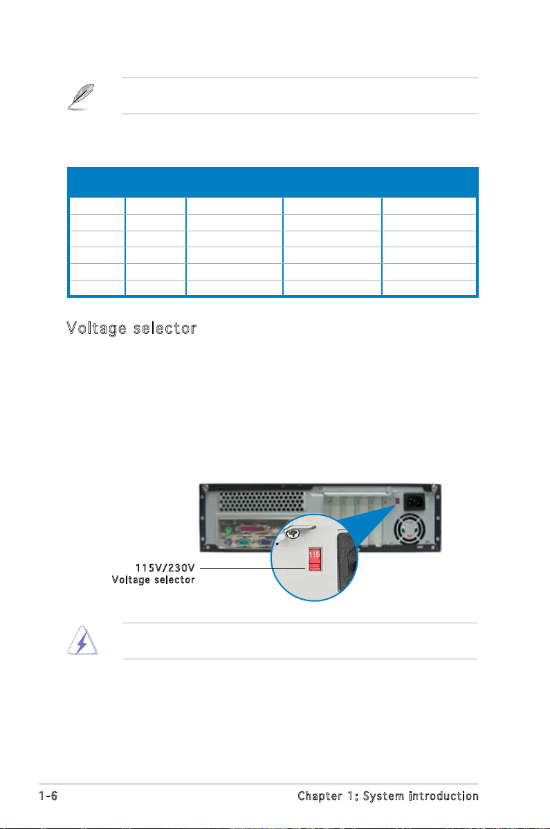
Vol ta ge se le ct or
The system’s power supply unit has a 115 V/230 V voltage selector
switch located beside the power connector. Use this switch to select the
appropriate system input voltage according to the voltage supply in your
area.
If the voltage supply in your area is 100-127 V, set this switch to 115 V.
If the voltage supply in your area is 200-240 V, set this switch to 230 V.
115 V / 2 30V
Vol t a g e sel e c t or
Setting the switch to 115V in a 230V environment or 230V in a 115V
environment will seriously damage the system!
1-6 Chapter 1: System introduction
Page 17
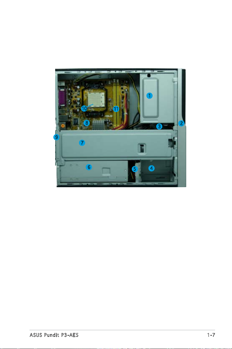
1.4 Internal components
The illustration below is the internal view of the system when you remove
the top cover. The installed components are labeled for your reference.
Proceed to Chapter 2 for instructions on installing additional system
components.
1
10
8
9
7
6
1. 5.25-inch empty optical drive bay
2. Front panel cover
3. Optical drive lock
4. Hard disk drive bays
5. Hard disk drive lock
6. Power supply unit
7. Chassis support bracket
11
3
4
5
8. ASUS motherboard
9. Metal bracket lock
10. AM2 socket
11. DIMM sockets
2
1-7ASUS Pundit P3-AE5
Page 18

1-8 Chapter 1: System introduction
Page 19

Chapter 2
This chapter provides step-by-step
instructions on how to install
components in the system.
Basic installation
Page 20
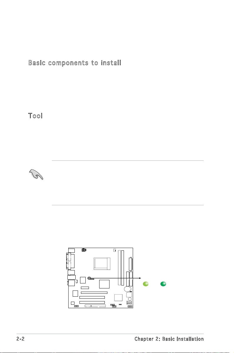
2.1 Preparation
SB_PWR
ON
Standy
Power
Powered
Off
OFF
Onboard LED
Before you proceed, make sure that you have all the components you plan
to install in the system.
Bas ic c omp on en ts to i nst al l
1. Central Processing Unit (CPU)
2. DDR2 Dual Inline Memory Module (DIMM)
3. Expansion card(s)
4. Hard disk drive
5. Optical drive
Too l
Phillips (cross) screw driver
2.2 Before you proceed
Take note of the following precautions before you install components into
the system.
•
Use a grounded wrist strap or touch a safely grounded object or
a metal object, such as the power supply case, before handling
components to avoid damaging them due to static electricity.
•
Hold components by the edges to avoid touching the ICs on them.
•
Whenever you uninstall any component, place it on a grounded
antistatic pad or in the bag that came with the component.
The motherboard comes with an onboard standby power LED. This LED
lights up to indicate that the system is ON, in sleep mode or in soft-off
mode, and not powered OFF. Unplug the power cable from the power outlet
and make sure that the standby power LED is OFF before installing any
system component.
2-2 Chapter 2: Basic installation
Page 21
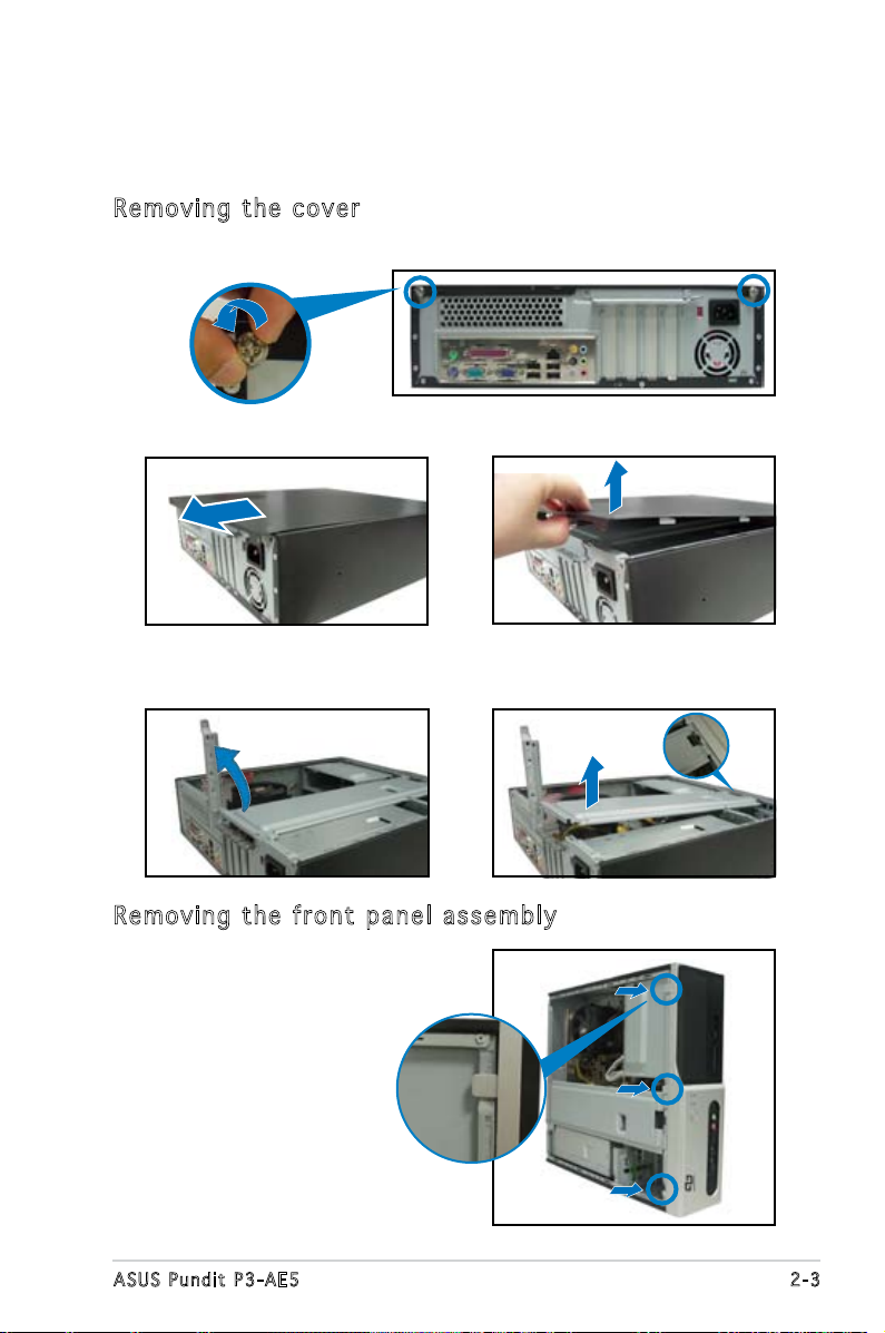
2.3 Removing the side cover and front
panel assembly
Remo vin g th e co ver
1. Remove the cover screws.
2. Pull the cover.
4. Lift the expansion card lock to
a 90º-100º angle.
3. Lift the cover, then set aside.
5. Lift the chassis support
bracket, then remove.
Remo vin g th e f ron t pa nel a ss emb ly
1. Locate the front panel
assembly hooks.
2. Pull the hooks outward to
remove.
2-3ASUS Pundit P3-AE5
Page 22
2.4 Central Processing Unit (CPU)
CPU Socket AM2
CPU Socket AM2
2.4 .1 Ove rv ie w
The motherboard comes with a 940-pin AM2 socket designed for the
AMD Athlon™ FX/AMD Athlon™ 64 X2/AMD Athlon™ 64/AMD Sempron™
processor.
Make sure you use a CPU is designed for the AM2 socket. The CPU ts in
only one correct orientation. DO NOT force the CPU into the socket to
prevent bending the connectors on the socket and damaging the CPU!
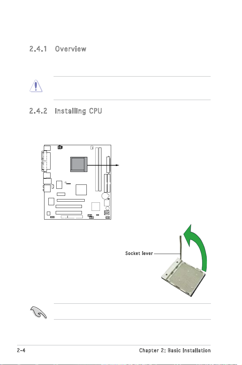
2.4 .2 Ins ta ll ing C PU
To install a CPU:
1. Locate the CPU socket on the motherboard.
2.
Unlock the socket by pressing the
lever sideways, then lift it up to a
90°-100° angle.
Make sure that the socket lever is lifted up to 90°-100° angle, otherwise
the CPU does not t in completely.
2-4 Chapter 2: Basic installation
Soc k e t leve r
Page 23
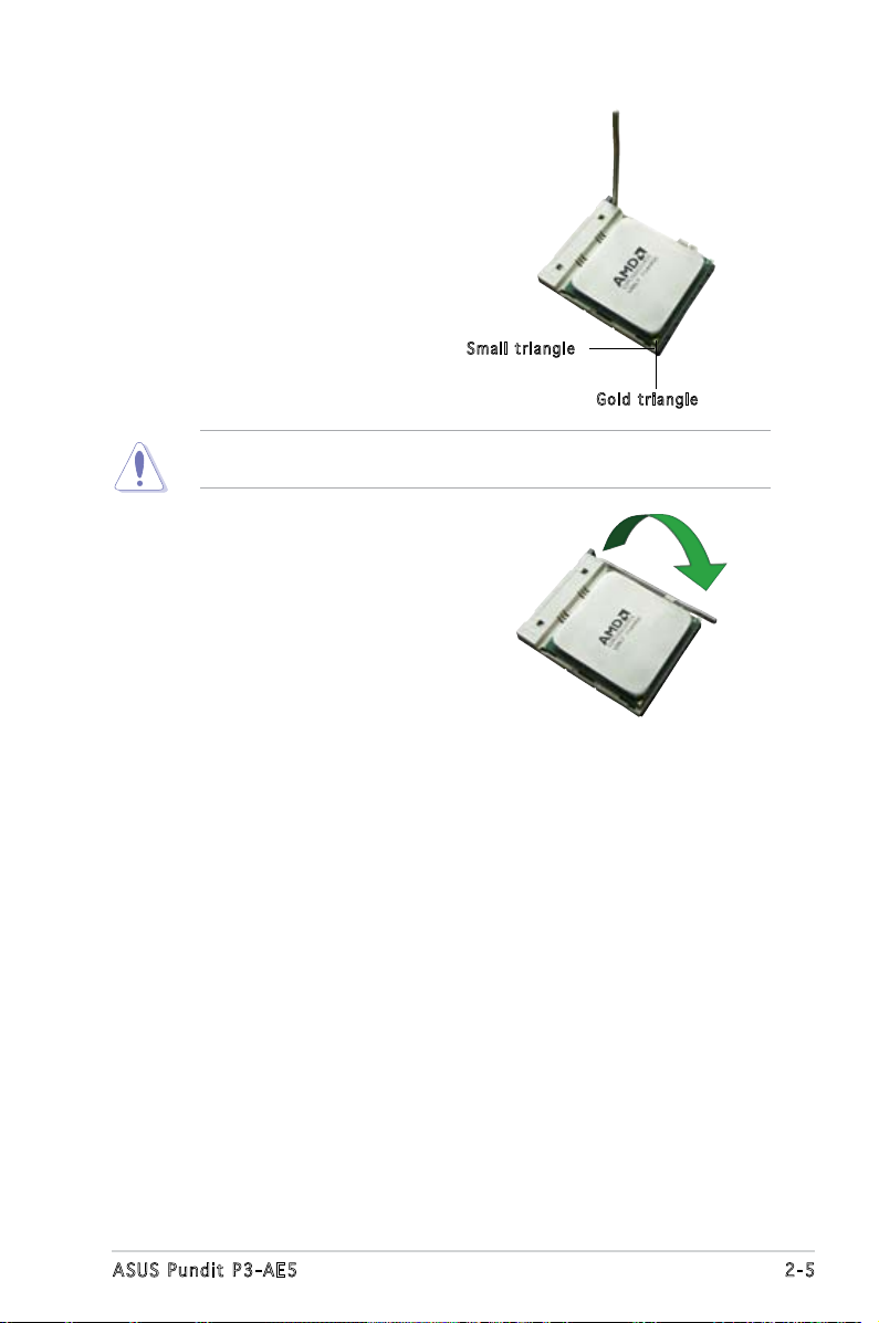
3. Position the CPU above the
socket such that the CPU corner
with the gold triangle matches
the socket corner with a small
triangle.
4. Carefully insert the CPU into the
socket until it ts in place.
The CPU ts only in one correct orientation. DO NOT force the CPU into
the socket to prevent bending the pins and damaging the CPU!
5. When the CPU is in place, push
down the socket lever to secure
the CPU. The lever clicks on the
side tab to indicate that it is
locked.
Sma l l trian g l e
Gol d t riang l e
2-5ASUS Pundit P3-AE5
Page 24
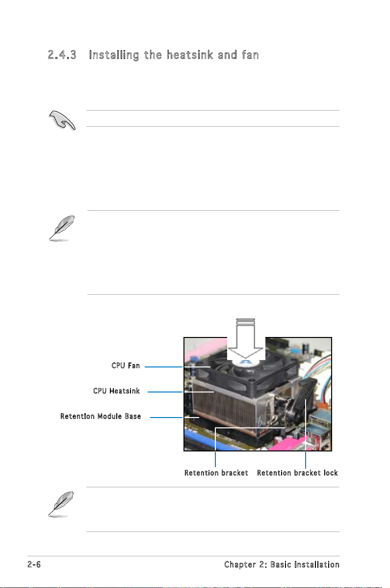
2.4 .3 Ins ta ll ing t he h e at si nk an d fa n
The AMD Athlon™ FX/AMD Athlon™ 64 X2/AMD Athlon™ 64/AMD
Sempron™ processor require a specially designed heatsink and fan assembly
to ensure optimum thermal condition and performance.
Make sure that you use only qualied heatsink and fan assembly.
Follow these steps to install the CPU heatsink and fan.
1. Place the heatsink on top of the installed CPU, making sure that the
heatsink ts properly on the retention module base.
• The retention module base is already installed on the motherboard
upon purchase.
• You do not have to remove the retention module base when
installing the CPU or installing other motherboard components.
• If you purchased a separate CPU heatsink and fan assembly, make
sure that a Thermal Interface Material is properly applied to the CPU
heatsink or CPU before you install the heatsink and fan assembly.
CPU F a n
CPU H e atsin k
Ret e n t ion M o d u le Ba s e
Ret e n t ion b r a c ket l o c kRet e n t ion b r a c ket
Your boxed CPU heatsink and fan assembly should come with installation
instructions for the CPU, heatsink, and the retention mechanism. If the
instructions in this section do not match the CPU documentation, follow
the latter.
2-6 Chapter 2: Basic installation
Page 25
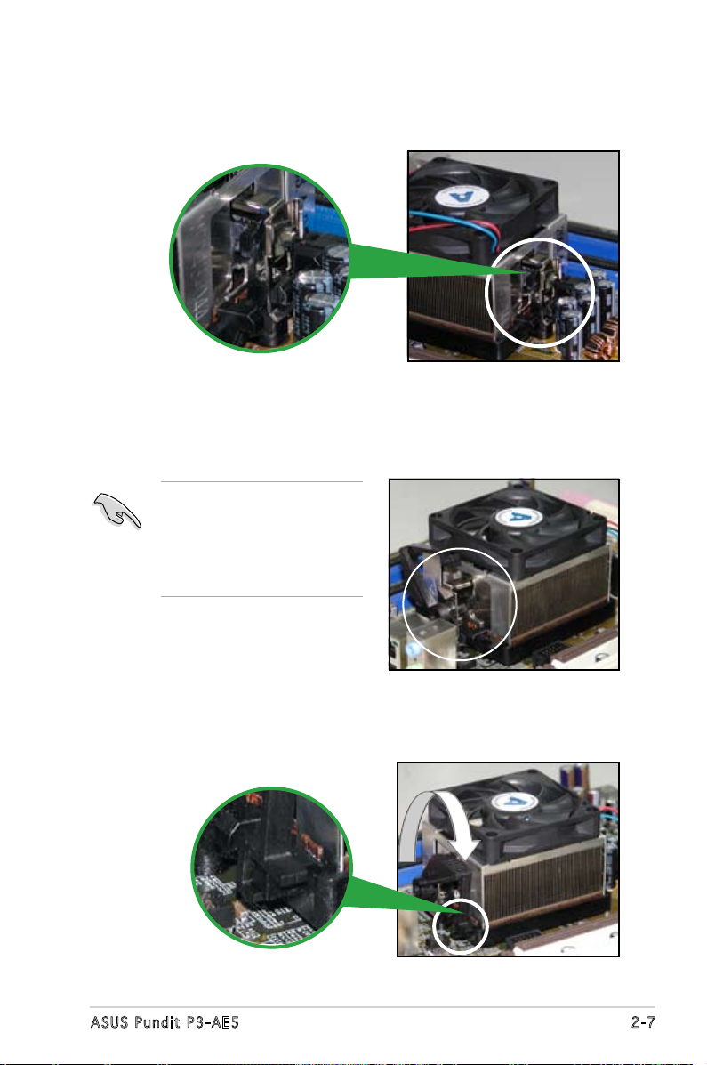
2. Attach one end of the retention bracket to the retention module base.
3. Align the other end of the retention bracket (near the retention
bracket lock) to the retention module base. A clicking sound denotes
that the retention bracket is in place.
Make sure that the fan and
heatsink assembly perfectly
ts the retention mechanism
module base; otherwise, you
cannot snap the retention
bracket in place.
4. Push down the retention bracket lock on the retention mechanism to
secure the heatsink and fan to the module base.
2-7ASUS Pundit P3-AE5
Page 26
DIMM_A1
DIMM_B1
240-pin DDR2 DIMM Sockets
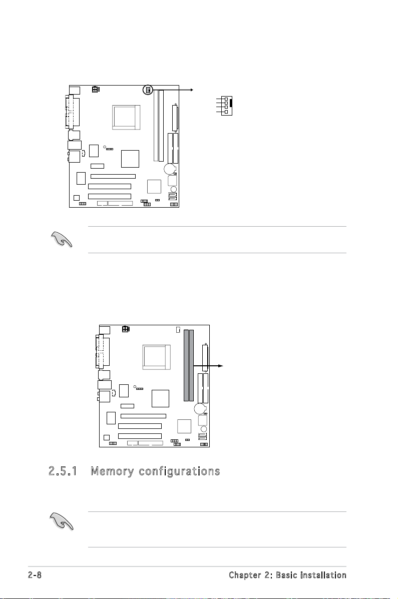
5. Connect the CPU fan cable to the CPU_FAN connector on the
CPU FAN PWM
CPU FAN IN
CPU FAN PWR
GND
CPU_FAN
CPU Fan connector
motherboard.
Do not forget to connect the CPU fan connector! Hardware monitoring
errors can occur if you fail to plug this connector.
2.5 Installing a DIMM
The system motherboard comes with two Double Data Rate 2 (DDR2) Dual
Inline Memory Module (DIMM) sockets.
The following gure illustrates the location of the sockets:
2.5 .1 Mem or y con fi gu rat io ns
You may install 256 MB, 512 MB, and 1 GB unbuffered ECC/non-ECC DDR2
DIMMs into the DIMM sockets.
For optimum compatibility, we recommend that you obtain memory
modules from the same vendor. Visit the ASUS website (www.asus.com)
for the latest Qualied Vendors List..
2-8 Chapter 2: Basic installation
Page 27
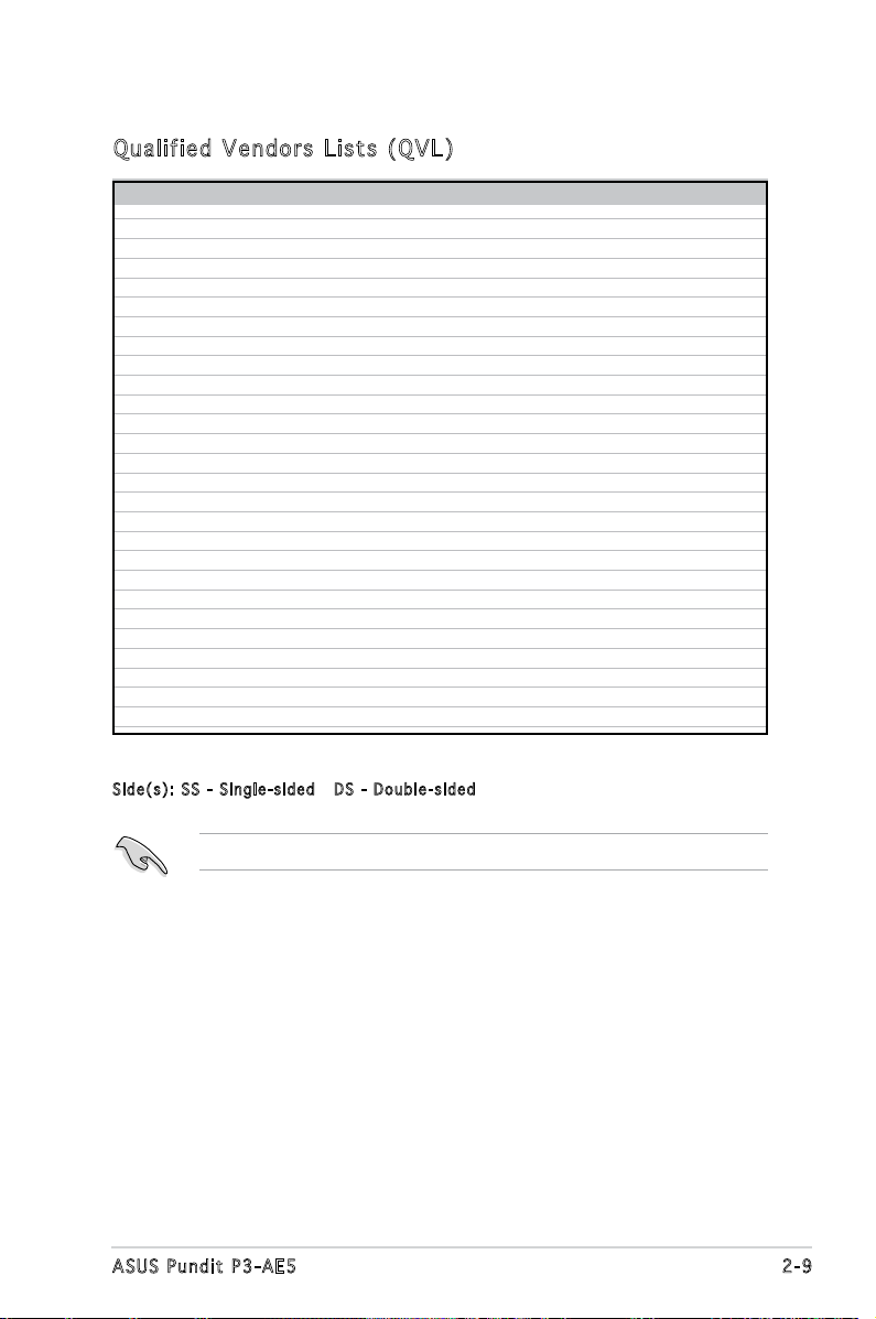
Qua l if i ed V en d ors Li s ts ( QV L )
Model Side(s) Chip Number Size Part Number
Kingston SS E5116AB-5C-E 256MB KVR533D2N4/256
Kingston SS E5116AF-5C-E 256MB KVR533D2N4/256
Kingston DS HY5PS56821 512MB KVR533D2N4/512
Kingston DS D6408TE7BL-37 1G KVR533D2N4/1G
Kingston SS E2508AB-6E-E 256MB KVR667D2N5/256
Kingston SS D6408TE8WL-27 512MB KVR667D2N5/512
Kingston SS E5108AE-6E-E 512MB KVR667D2E5/512
Samsung SS K4T51083QB-GCD5 512MB M378T6553BG0-CD5
Samsung SS K4T51083QC 512MB KR M378T6553CZ0-CE6
Samsung DS K4T56083QF-ZCE6 512MB KR M378T6453FZ0-CE6
Samsung SS K4T51083QC-ZCE6 1G KR M378T2953CZ0-CE6
Inneon SS HYB18T512160AF-3.7AFSS31270 256MB HYS64T32000HU-3.7-A
Inneon SS HYB18T512800AC37SSS11511 512MB HYS64T64000GU-3.7-A
Inneon SS HYB18T512800AF37SSS12079 512MB HYS64T64000HU-3.7-A
Inneon SS HYB18T512800AF37FSS29334 512MB HYS64T64000HU-3.7-A
Inneon SS HYB18T5128000AF-3SSSS27416 512MB HYS64T32000HU-3S-A
Inneon SS HYB18T512800AF3SFSS05346 512MB HYS64T64000HU-3S-A
Inneon DS HYB18T512800AF3SSSS28104 1G HYS64T128020HU-3S-A
Micron DS D9BOM 512MB MT 16HTF6464AG-53EB2
Micron DS D9CRZ 1G MT 16HTF12864AY-53EA1
Corsair DS MIII0052532M8CEC 512MB VS512MB533D2
HY SS HY5PS12821AFP-Y4 512MB HYMP564U64AP8-Y4 AA
Kingmax SS KKEA88B4IAK-37 512MB KLBC28F-A8KB4
Kingmax SS E5116AB-5C-E 256MB KLBB68F-36EP4
Kingmax SS E5108AE-6E-E 512MB KLCC28F-A8EB5
VDATA SS VD29608A8A-3EC20615 512MB M2GVD5G3H31A4I1C52
VDATA DS VD29608A8A-3EC20620 1G M2GVD5G3I41C4I1C52
DIMM support
Sid e ( s ): SS - Singl e - s ided D S - D o u b l e-si d e d
Visit the ASUS website for the latest DDR2-667/533 MHz QVL.
2-9ASUS Pundit P3-AE5
Page 28
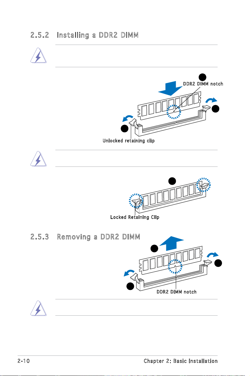
2.5 .2 Ins ta ll ing a D DR2 D IM M
Make sure to unplug the power supply before adding or removing DIMMs
or other system components. Failure to do so may cause severe damage
to both the motherboard and the components.
1. Unlock a DDR2 DIMM socket
by pressing the retaining clips
outward.
2. Align a DIMM on the socket
such that the notch on the
DIMM matches the break on
the socket.
Unl o c k ed re t a i ning c l i p
A DDR2 DIMM is keyed with a notch so that it ts in only one direction.
DO NOT force a DIMM into a socket to avoid damaging the DIMM.
1
2
DDR 2 D IMM n o t c h
1
3. Firmly insert the DIMM into the
3
socket until the retaining clips
snap back in place and the DIMM
is properly seated.
Loc k e d Reta i n i ng Cl i p
2.5 .3 Rem ov in g a D DR 2 D IM M
Follow these steps to remove a DIMM.
1. Simultaneously press the
retaining clips outward to
unlock the DIMM.
1
Support the DIMM lightly with your ngers when pressing the retaining
clips. The DIMM might get damaged when it ips out with extra force.
2. Remove the DIMM from the socket.
2-10 Chapter 2: Basic installation
2
DDR 2 D IMM n o t c h
1
Page 29
2.6 Expansion slots
In the future, you may need to install expansion cards. The motherboard
has two PCI, one PCI Express™ x1, and one PCI Express™ x16 slot. The
following sub-sections describe the slots and the expansion cards that they
support.
The system supports low prole PCI, PCI Express x16, and PCI Express
x1 cards. You can only install low prole expansion cards on this system.
Ask your retailer for details.
2.6 .1 Exp an si on sl ot s
PCI sl o ts
The PCI slots support cards such as a LAN card, SCSI card, USB card,
andother cards that comply with PCI specications.
PCI Ex p res s x 1 6 s l ot
This motherboard supports PCI Express x16 graphic cards that comply with
the PCI Express specications. The following gure shows a graphics card
installed on the PCI Express x16 slot.
PCI Ex p res s x 1 sl o t
This motherboard supports PCI Express x1 network cards, SCSI cards and
other cards that comply with the PCI Express specications.
Before installing an expansion card, read the documentation that came
with it and make the necessary hardware settings for the card.
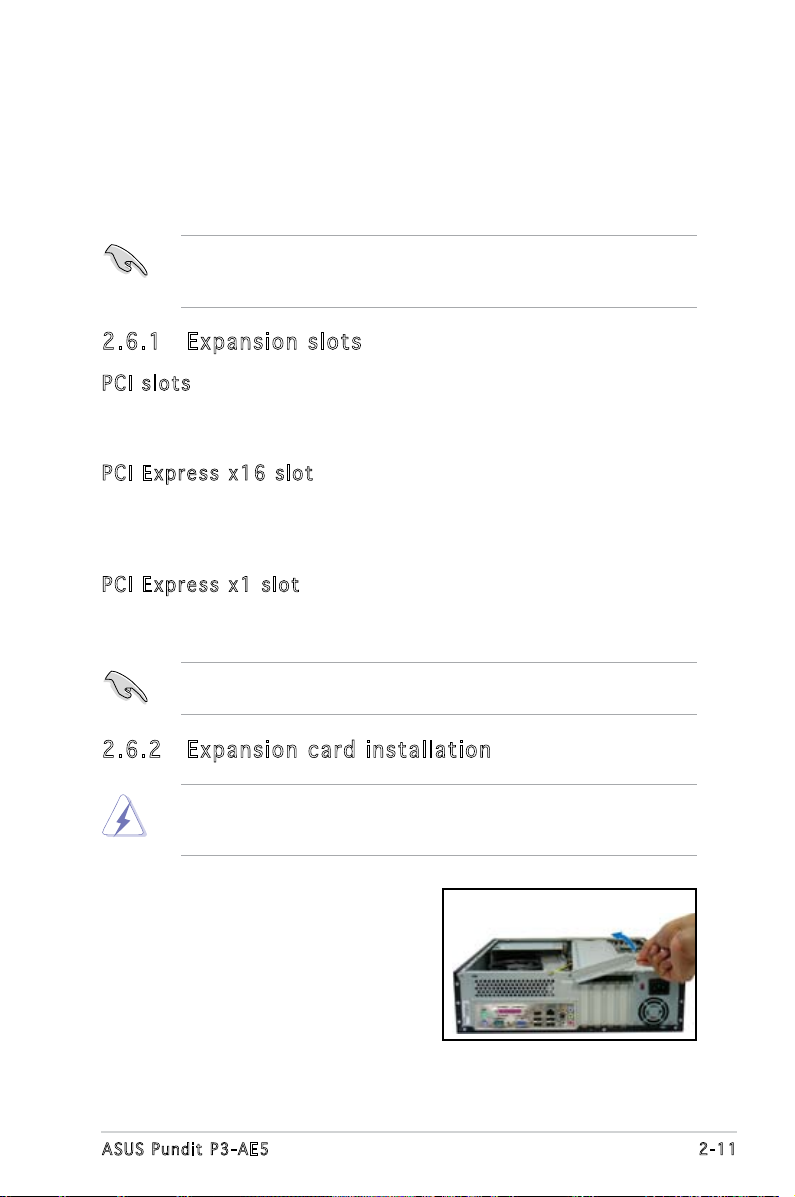
2.6 .2 Exp an si on ca rd in st al lat io n
Make sure to unplug the power cord before adding or removing
expansion cards. Failure to do so may cause you physical injury and
damage motherboard components.
To install an expansion card:
1. Lay the system on its side on a
at and stable surface.
2. Lift the expansion card lock to a
90º-100º angle.
2-11ASUS Pundit P3-AE5
Page 30

2. Remove the chassis support
bracket.
3. Remove the metal cover opposite
the slot that you intend to use.
4. Align the card connector with
the slot and press rmly until
the card is completely seated
on the slot.
5. If you have already installed a hard
disk drive, replace the chassis
support bracket; otherwise,
install other components before
replacing the chassis support
bracket.
6. Replace the expansion card lock
to secure the card to the chassis.
2-12 Chapter 2: Basic installation
Page 31

Sta n da r d i n te r rup t a s sig n me n ts
IRQ Pri o r i t y Sta n d a r d Fu n c t i on
0 1 System Timer
1 2 Keyboard Controller
2 – Re-direct to IRQ#9
3 11 IRQ holder for PCI steering*
4 12 Communications Port (COM1)*
5 13 IRQ holder for PCI steering*
6 14 Floppy Disk Controller
7 15 Printer Port (LPT1)*
8 3 System CMOS/Real Time Clock
9 4 IRQ holder for PCI steering*
10 5 IRQ holder for PCI steering*
11 6 IRQ holder for PCI steering*
12 7 PS/2 Compatible Mouse Port*
13 8 Numeric Data Processor
14 9 Primary IDE Channel
15 10 Secondary IDE Channel
* T h e s e IRQ s a re us u a l l y av a i l a ble f o r ISA o r P CI d e v i c es.
IRQ as s ign m en t s f o r t his mo t her b oa r d
A B C D
PCI slot 1 used — — —
PCI slot 2 — used — —
When using PCI cards on shared slots, ensure that the drivers support
“Share IRQ” or that the cards do not need IRQ assignments. Otherwise,
conicts will arise between the two PCI groups, making the system
unstable and the card inoperable.
2-13ASUS Pundit P3-AE5
Page 32

2.7 Installing an optical drive
Refer to the instructions in this section if you wish to install a new optical
drive.
Follow these steps to install an optical drive:
1. Drive a screw on the top right
screw hole on both sides of
the drive.
2. Connect the IDE and audio
cable at the back of the drive.
3. Push the drive all the way into
the bay until the drive lock clicks.
4. Connect a 4-pin power plug
from the power supply unit to
the power connector at the
back of the drive.
2-14 Chapter 2: Basic installation
Page 33

Uni ns ta lli ng t he op ti cal d ri ve
In the future, you may have to upgrade or replace a defective optical drive.
To uninstall the optical drive:
1. Remove the front panel assembly following the instructions in section
“2.3.2 Removing the front panel assembly”.
2. Locate the optical drive screw
lock.
3. Push the lock to release the
optical drive screw (A), then
slightly pull the drive out from
the bay (B).
4. Disconnect the IDE, audio, and
power cables and plugs from the
back of the drive.
5. Pull out the drive completely
from the bay, then replace it
following the instructions in the
previous section.
A
B
2-15ASUS Pundit P3-AE5
Page 34

2.8 Removing the card reader
In the future, you may have to remove or replace the 6-in-1 card reader.
To uninstall the card reader:
1. Remove the front panel assembly following the instructions in “2.3.2
Removing the front panel assembly”.
2. Locate the lock on both sides of
the card reader assembly.
3. Press the card reader lock
inwards(A), then slightly pull the
card reader assembly outward
(B) until the USB cable and plug
is exposed.
A
B
4. Disconnect the USB cable and
plug from the card reader
assembly, then set the card
reader assembly aside.
2-16 Chapter 2: Basic installation
Page 35

2.9 Installing hard disk drives (HDDs)
The system comes with two 3.5-inch drive bays (labeled 1 and 2) for
installation of two Serial ATA hard disk drives or one IDE HDD (if you have
installed an optical drive).
2.9 .1 Har d di sk dr iv e b ay s
The drive bays incorporate a
screw-less design that allows you
to install and remove a hard disk
drive without driving screws on the
chassis. Each drive bay has a HDD
screw lock and four screws rails (two
on each side of the bay) that trap
the HDD screws and secure the drive
in the place.
HDD s c rew l o c k
When installing one hard disk drive, install it on the upper HDD bay.
2.9 .2 SAT A ha rd di sk dr iv e ins ta ll ati on
To install a SATA hard disk drive:
Scr e w rails
1
2
Scr e w rails
1. Insert the rubber washers to
the HDD screws. Refer to the
illustration on the right.
2. Drive four screws (two on
each side of the drive) on the
drive screw holes.
2
Rubber washer mat
1
Rub b e r wash e r
2
2-17ASUS Pundit P3-AE5
Page 36

3. Connect one end of the
supplied 7-pin SATA cable
to the SATA connector at
the back of the drive, then
connect the other end to
a SATA connector on the
motherboard. See page 4-7
for the location of the SATA
connectors.
4. Connect the 15-pin SATA power
plug from the power supply unit
to the power connector at the
back of the drive.
5. Place the HDD on the tray.
Make sure that the HDD
screws are aligned with the
screw holes and rails.
6. When the HDD screws align
with the screw rails, push
HDD s c rew l o c k
the drive carefully until it is
completely ushed on the bay.
The HDD screw lock clicks
to indicate that the drive is
properly in place.
2-18 Chapter 2: Basic installation
Page 37

2.9 .3 IDE h ar d d is k dri ve i nst al la tio n
Set the IDE HDD as master device before connecting the IDE cable and
power plug. Refer to the HDD documentation for details.
To install an IDE hard disk drive:
1. Follow steps 1 to 2 of the previous section.
2. Connect the IDE cable (gray connector) to the IDE interface at the
back of the drive. Match the red stripe on the cable with Pin 1 on the
IDE interface.
3. Connect a power cable from the power supply unit to the power
connector at the back of the drive.
4. Follow steps 5 to 6 of the previous section to complete installation.
2.9 .4 Uni ns ta lli ng a ha rd d isk d ri ve
In the future, you may have to upgrade or replace a defective hard disk
drive.
To uninstall the hard disk drive:
1. Press the HDD screw lock (A),
then push the drive out from
the bay (B) until the drive
screws are released from the
screw rails.
B
A
2. Slightly lift the HDD, then
remove all plugs at the back of
the drive.
3. Install a new HDD following the
instructions in the previous
section.
2-19ASUS Pundit P3-AE5
Page 38

2.10 Replacing the covers
After you install all the necessary components on the system, replace the
covers following the instructions in this section:
2.1 0. 1 R ep la c in g th e f ro nt pa ne l a ss em bl y
To replace the front panel assembly:
1. Hook the hinge-like tabs to the holes on the right side of the chassis.
Hin g e - like t a b s
2. Swing the left edge of the front panel inward, then attach the front
panel assembly hooks to the chassis until they snap in place.
Do not use too much force when replacing the front panel assembly.
2-20 Chapter 2: Basic installation
Page 39

2.1 0. 2 R ep la c in g th e s ys te m c ov er
To replace the metal chassis support:
1. Reinstall the metal chassis
support and the expansion
card lock.
2. Match and insert the hooks
of the cover to the elongated
holes on the side of the
chassis. All eight hooks (four
hooks on both sides) of the
cover must properly t the
designated holes.
3. Slide the cover toward the front
panel until it is in place.
4. Replace the cover screws.
2-21ASUS Pundit P3-AE5
Page 40

2.11 Installing the foot stands
You need to install the foot stands to place the system vertically on your
desktop.To install the foot stands:
1. Lay the system on its side on a
at, stable, and elevated surface,
then locate two screw holes on
the left side of the system.
2. Extend the left side of the
system at least 3 cm from the
edge of the surface to facilitate
installation.
3. Align the foot stand and chassis
screw holes.
4. Drive in a screw to secure the
footstand to the chassis.
5. Follow the same procedures when
installing the second foot stand.
The photo on the right shows
the system in a vertical desktop
placement.
2-22 Chapter 2: Basic installation
Page 41

Chapter 3
This chapter helps you power up
the system and install drivers and
utilities from the support CD.
Starting up
Page 42

3.1 Installing an operating system
The barebone system supports Windows® 2000/XP operating systems
(OS). Always install the latest OS version and corresponding updates so
you can maximize the features of your hardware.
• Motherboard settings and hardware options vary. Use the setup
procedures presented in this chapter for reference only. Refer to
your OS documentation for detailed information.
®
• Make sure that you install Windows
Windows® XP Service Pack 1 or later versions before installing the
drivers for better compatibility and system stability.
2000 Service Pack 4 or the
3.2 Powering up
Press the system power button ( ) to enter the OS.
Pre s s to tu r n ON th e s y stem
3-2 Chapter 3: Starting up
Page 43

3.3 Support CD information
The support CD that came with the system contains useful software and
several utility drivers that enhance the system features.
•
Screen display and driver options may not be the same for different
operating system versions.
•
The contents of the support CD are subject to change at any time
without notice. Visit the ASUS website for updates.
3.3 .1 Run ni ng th e su ppo rt C D
To begin using the support CD, place the CD in your optical drive. The
CD automatically displays the Drivers menu if Autorun is enabled in your
computer.
Cli c k an ic o n to
dis p l a y sup p o r t
CD/ m o t herbo a r d
inf o r m ation
Cli c k an it e m to in s t a ll
If Autorun is NOT enabled in your computer, browse the contents of the
support CD to locate the le ASSETUP.EXE from the BIN folder.
Double-click the ASSETUP.EXE to run the CD.
3-3ASUS Pundit P3-AE5
Page 44

3.3 .2 Dri ve rs me nu
The drivers menu shows the available device drivers if the system detects
installed devices. Install the necessary drivers to activate the devices.
AMD Co o l ‘ n ’ Q uie t D r ive r
Installs the AMD Cool ‘n’ Quiet driver.
VIA Ch i pse t D r ive r P r ogr a m
Installs the VIA chipset driver program.
VIA S3 G Di s pl a y D r iv e r
Installs the VIA S3G display driver.
Rea l te k Au d io Dri v er
Installs the Realtek® audio driver.
Rea l te k RT L 81 0 0S L AN Dri v er
Installs the Realtek® RTL8100S LAN driver.
The screen display and drivers option may not be the same for different
operating system versions.
3-4 Chapter 3: Starting up
Page 45
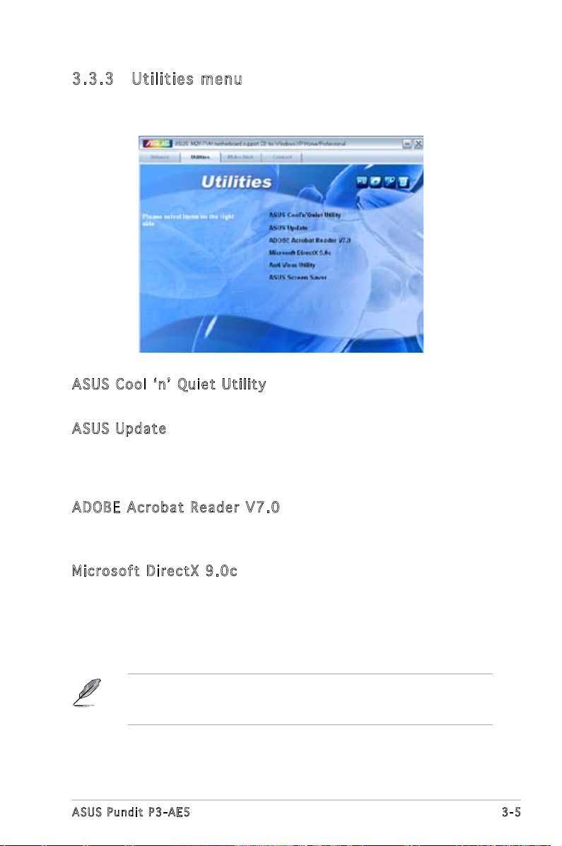
3.3 .3 Uti li ti es me nu
The Utilities menu shows the applications and other software that the
motherboard supports.
ASU S C o ol ‘ n’ Qui e t U til i ty
Installs the ASUS Cool ‘n’ Quiet utility.
ASU S U p dat e
The ASUS Update utility allows you to update the motherboard BIOS in a
Windows® environment. This utility requires an Internet connection either
through a network or an Internet Service Provider (ISP).
ADO B E A cro b at Rea d er V7. 0
The Adobe® Acrobat® Reader V7.0 is for opening, viewing, and printing
documents in Portable Document Format (PDF).
Mic r os o ft D ir e ctX 9. 0 c
The Microsoft® DirectX® 9.0c is a multimedia technology that enhances
computer graphics and sounds. DirectX® improves the multimedia features
of your computer so you can enjoy watching TV and movies, capturing
videos, or playing games on your computer.
Microsoft® Windows® XP Service Pack 2 already includes Microsoft®
DirectX® 9.0c. If your system is Microsoft® Windows® XP Service
Pack 2-embedded, skip Microsoft® DirectX® 9.0c installation.
3-5ASUS Pundit P3-AE5
Page 46

Ant i -V i rus ut i lit y
The anti-virus utility scans, identies, and removes computer viruses. View
the online help for detailed information.
ASU S S c ree n S a ver
Installs the ASUS screen saver.
The screen display and utilities option may not be the same for different
operating system versions.
3.3 .4 Mak e Di sk me nu
The Make Disk menu allows you to make a RAID driver disk.
VIA VT 8 237 RAI D C o ntr o ll e r D r iv e r
Allows you to create a VIA® VT8237 RAID driver disk.
3-6 Chapter 3: Starting up
Page 47

3.3 .5 ASU S Co nta ct i nfo rm at ion
Click the Contact tab to display the ASUS contact information. You can also
nd this information on the inside front cover of this user guide.
3-7ASUS Pundit P3-AE5
Page 48

3-8 Chapter 3: Starting up
Page 49

Chapter 4
This chapter gives information
about the motherboard that comes
with the system. This chapter
includes the motherboard layout,
jumper settings, and connector
locations.
Motherboard information
Page 50

4.1 Introduction
ATX12V
COM1VGA
Parallel Port
PS2/2KBMS
T:Mouse
B:Keyboard
CPU_FAN
EATXPWR
DDR2 DIMM_A1 (64 bit, 240-pin module)
DDR2 DIMM_B1 (64 bit, 240-pin module)
USB56
LOPPYCOM2
PCI2
PCI1
PCIEX16
PCIEX1_1
RTL8100S
IT8716F-S
ALC880
AAFP
CD
USB78
CLRTC
SATA2
SATA1
BUZZER
BIOS_WP
F_PANEL
PRI_IDE
SEC_IDE
USB12
LAN_USB34
SB_PWR
IR_CON
4Mb
BIOS
CR2032 3V
Lithium Cell
CMOS Power
KBPWR
The Pundit P3-AE5 barebone system comes with an ASUS motherboard.
This chapter provides technical information about the motherboard for
future upgrades or system reconguration.
4.2 Motherboard layout
4-2 Ch a p t e r 4 : M o t h e r b o a r d i n f o
Page 51

4.3 Jumpers
CLRTC
Normal
(Default)
1 2 2 3
Clear CMOS
Clear RTC RAM
1. C l e ar R T C RAM ( C L RTC)
This jumper allows you to clear the Real Time Clock (RTC) RAM in
CMOS. You can clear the CMOS memory of date, time, and system
setup parameters by erasing the CMOS RTC RAM data. The onboard
button cell battery powers the RAM data in CMOS, which include
system setup information such as system passwords.
To erase the RTC RAM:
1. Turn OFF the computer and unplug the power cord.
2. Remove the onboard battery.
3. Move the jumper cap from pins 1-2 (default) to pins 2-3. Keep
the cap on pins 2-3 for about 5-10 seconds, then move the cap
back to pins 1-2.
4. Reinstall the battery.
5. Plug the power cord and turn ON the computer.
6. Hold down the <Del> key during the boot process and enter BIOS
setup to re-enter data.
Except when clearing the RTC RAM, never remove the cap on CLRTC
jumper default position. Removing the cap will cause system boot failure!
• You do not need to clear the RTC when the system hangs due to
overclocking. For system failure due to overclocking, use the C.P.R.
(CPU Parameter Recall) feature. Shut down and reboot the system
so the BIOS can automatically reset parameter settings to default
values.
• Due to the chipset limitation, AC power off is required prior using
C.P.R. function. You must turn off and on the power supply or unplug
and plug the power cord before reboot the system.
4-3ASUS Pundit P3-AE5
Page 52

3. K e y boar d p ower ( 3 -pin K B PWR)
KBPWR
1
2 2
3
+5V
(Default)
+5VSB
Fan connectors
FLOPPY
PIN1
NOTE:Orient the red markings on
the floppy ribbon cable to PIN1.
Floppy disk drive connector
This jumper allows you to enable or disable the keyboard wake-up
feature. Set this jumper to pins 2-3 (+5VSB) to wake up the computer
when you press a key on the keyboard (the default is the Space Bar).
This feature requires an ATX power supply that can supply at least
500 mA on the +5VSB lead, and a corresponding setting in the BIOS.
4.4 Connectors
1. F l o ppy d i s k dr i v e con n e c tor ( 3 4 -1 p i n FLOP P Y )
This connector is for the provided oppy disk drive (FDD) signal cable.
Insert one end of the cable to this connector, then connect the other
end to the signal connector at the back of the oppy disk drive.
Pin 5 on the connector is removed to prevent incorrect cable connection
when using a FDD cable with a covered Pin 5.
4-4 Ch a p t e r 4 : M o t h e r b o a r d i n f o
Page 53

2. S e r ial A T A con n e c tors
SATA1
GND
RSATA_TXP1
RSATA_TXN1
GND
RSATA_RXP1
RSATA_RXN1
GND
SATA2
GND
RSATA_TXP2
RSATA_TXN2
GND
RSATA_RXP2
RSATA_RXN2
GND
SATA connectors
(7-p i n SATA 1 , SATA 2 )
These connectors are for the Serial ATA signal cables for Serial ATA
hard disk and optical disk drives that allows up to 150 MB/s data
transfer rates, faster than the standard parallel ATA with 133 MB/s
(Ultra DMA133).
If you install Serial ATA hard disk drives, you can create a RAID 0,
RAID 1, and JBOD conguration through the onboard VIA
®
VT8237R
Plus controller.
Install the Windows® 2000 Service Pack 4 or the Windows® XP Service
Pack1 before using Serial ATA.
• For detailed instructions on how to congure RAID 0, 1, and
JBOD, refer to the RAID manual in the support CD.
• The RAID function of these connectors is set to [Disabled] by
default. See section “5.4.4 Onboard Device Conguration” for
details.
4-5ASUS Pundit P3-AE5
Page 54

3 ID E con n e c tor ( 4 0 -1 p i n PRI_ E I D E)
PRI_IDE
SEC_IDE
NOTE:Orient the red markings
(usually zigzag) on the IDE
ribbon cable to PIN1.
PIN1
IDE connectors
PIN1
The onboard IDE connectors are for Ultra DMA 133/100/66 signal
cable(s). There are three connectors on each Ultra DMA 133/100/66
signal cable: blue, black, and gray. Connect the blue connector to the
motherboard’s IDE connector, then select one of the following modes
to congure your device(s).
Drive jumper setting Mode of
Cable connector
device(s)
Single device Cable-Select or Master - Black
Two devices Cable-Select Master
Black
Slave Gray
Master Master Black or gray
Slave Slave
• Pin 20 on the IDE connector is removed to match the covered hole
on the Ultra DMA cable connector. This prevents incorrect insertion
when you connect the IDE cable.
• Use the 80-conductor IDE cable for Ultra DMA 133/100/66 IDE
devices.
If any device jumper is set as “Cable-Select”, make sure all other device
jumpers have the same setting.
4. C P U Fan C o nnec t o r s
(4-p i n CPU_ F A N )
The fan connectors support cooling fans of 350mA~740mA (8.88W
max.) or a total of 1A~2.22A (26.64W max.) at +12V. Connect the fan
cables to the fan connectors on the motherboard, making sure that the
black wire of each cable matches the ground pin of the connector.
4-6 Ch a p t e r 4 : M o t h e r b o a r d i n f o
Page 55

Do not forget to connect the fan cables to the fan connectors.
CPU FAN PWM
CPU FAN IN
CPU FAN PWR
GND
CPU_FAN
Fan connectors
USB56
GND
USB_P5+
USB_P5-
USB+5V
GNDNCUSB_P6+
USB_P6-
USB+5V
USB78
GND
USB_P7+
USB_P7-
USB+5V
GND
NC
USB_P8+
USB_P8-
USB+5V
USB connectors
Insufcient air ow inside the system may damage the motherboard
components. These are not jumpers! Do not place jumper caps on the
fan connectors!
5. U S B con n e c tors ( 1 0-1 p i n USB 5 6 , USB 7 8 )
These connectors are for USB 2.0 ports. Connect the USB module
cable to any of these connectors, then install the module to a slot
opening at the back of the system chassis. These USB connectors
comply with USB 2.0 specication that supports up to 480 Mbps
connection speed.
Never connect a 1394 cable to the USB connectors. Doing so will
damage the motherboard!
The USB module is purchased separately.
4-7ASUS Pundit P3-AE5
Page 56

+12V DC
GND
+12V DC
GND
ATX12V
EATXPWR
+3 Volts
+3 Volts
Ground
+5 Volts
Ground
+5 Volts
Ground
Power OK
+5V Standby
+12 Volts
+12 Volts
+3 Volts
+3 Volts
-12 Volts
Ground
PSON#
Ground
Ground
Ground
-5 Volts
+5 Volts
+5 Volts
+5 Volts
Ground
ATX power connectors
6. A T X pow e r conn e c t ors ( 2 4 -pin E A TXPW R , 4-pi n A TX12 V )
These connectors are for an ATX power supply. The plugs from
the power supply are designed to t these connectors in only one
orientation. Find the proper orientation and push down rmly until the
connectors completely t.
•
We recommend that you use an ATX 12 V Specication
2.0-compliant power supply unit (PSU) with a minimum of 300 W
power rating. This PSU type has 24-pin and 4-pin power plugs.
•
If you intend to use a PSU with 20-pin and 4-pin power plugs, make
sure that the 20-pin power plug can provide at least 15 A on +12
V and that the PSU has a minimum power rating of 300 W. The
system may become unstable or may not boot up if the power is
inadequate.
•
Do not forget to connect the 4-pin ATX +12 V power plug;
otherwise, the system will not boot up.
• We recommend that you use a PSU with higher power output when
conguring a system with more power-consuming devices. The
system may become unstable or may not boot up if the power is
inadequate.
•
You must install a PSU with a higher power rating if you intend to
install additional devices.
4-8 Ch a p t e r 4 : M o t h e r b o a r d i n f o
Page 57

7. F r o nt p a n e l au d i o con n e c tor ( 1 0 -1 p i n AAFP )
Analog front panel connector
BLINE_OUT_L
MIC2
LINE_OUT_L
BLINE_OUT_R
NC
MICPWR
+5VA
AGND
AAFP
COM2
PIN1
COM port connector
This connector is for a chassis-mounted front panel audio I/O module
that supports the Azalia audio standard. Connect one end of the front
panel audio I/O module cable to this connector.
8. S e r ial p o r t co n n e ctor ( 1 0-1 p i n COM 2 )
This connector is for serial (COM) port. Connect the serial port module
cable to this connector, then install the module to a slot opening at
the back of the system chassis.
The serial port bracket (COM) is purchased separately.
4-9ASUS Pundit P3-AE5
Page 58

9. S y s tem p a n el c o n n ecto r ( 2x5 1 0 pin F _ P ANEL )
System panel connector
HDLED+
HDLED-
GND
RESET
PLED+
PLED-
PWR
GND
F_PANEL
This connector supports several chassis-mounted functions.
•
System power LED
This 3-pin connector is for the system power LED. Connect the
chassis power LED cable to this connector. The system power LED
lights up when you turn on the system power, and blinks when the
system is in sleep mode.
•
Hard disk drive activity LED
This 2-pin connector is for the HDD Activity LED. Connect the HDD
Activity LED cable to this connector. The IDE LED lights up or ashes
when data is read from or written to the HDD.
•
System warning speaker
This 4-pin connector is for the chassis-mounted system warning
speaker. The speaker allows you to hear system beeps and warnings.
•
Power/Soft-off button
This connector is for the system power button. Pressing the power
button turns the system ON or puts the system in SLEEP or SOFT-OFF
mode depending on the BIOS settings. Pressing the power switch for
more than four seconds while the system is ON turns the system OFF.
•
Reset button
This 2-pin connector is for the chassis-mounted reset button for
system reboot without turning off the system power.
4-10 Ch a p t e r 4 : M o t h e r b o a r d i n f o
Page 59

10. O p t ical d r ive a u d io I n c onn e c t o r ( 4 - p in C D )
CD
Right Audio Channel
GND
GND
Left Audio Channel
Internal audio connector
This connector allows you to receive stereo audio input from sound
sources such as a CD-ROM, TV tuner, or MPEG card.
4-11ASUS Pundit P3-AE5
Page 60

4-12 Ch a p t e r 4 : M o t h e r b o a r d i n f o
Page 61

Chapter 5
This chapter tells how to change
system settings through the BIOS
Setup menus and describes the
BIOS parameters.
BIOS setup
1
Page 62

5.1 Managing and updating your BIOS
The following utilities allow you to manage and update the motherboard
Basic Input/Output System (BIOS) setup.
1. ASUS EZ Flash (Updates the BIOS using a oppy disk during POST.)
2. ASUS AFUDOS (Updates the BIOS using a bootable oppy disk in DOS
mode.)
3. ASUS Update (Updates the BIOS in Windows® environment.)
Refer to the corresponding sections for details on these utilities.
• Save a copy of the original motherboard BIOS le to a bootable
oppy disk in case you need to restore the BIOS in the future. Copy the
original motherboard BIOS using the AFUDOS utility.
• Visit the ASUS website (www.asus.com) and download the latest
BIOS le for this motherboard using the ASUS Update utility.
5.1 .1 Cre at in g a b oo tab le f lop py d isk
1. Do either one of the following to create a bootable oppy disk.
DOS environment
a. Insert a 1.44MB oppy disk into the drive.
b. At the DOS prompt, type
Windows® XP environment
a. Insert a 1.44 MB oppy disk to the oppy disk drive.
b. Click
Start from the Windows® desktop, then select My Computer.
c. Select the 3 1/2 Floppy Drive icon.
d. Click
File from the menu, then select Format. A Format 3 1/2
Floppy Disk window appears.
e. Select
Create an MS-DOS startup disk from the format options
eld, then click Start.
Windows® 2000 environment
To create a set of boot disks for Windows
a. Insert a formatted, high density 1.44 MB oppy disk into the drive.
b. Insert the Windows
c. Click
Start, then select Run.
d. From the Open eld, type
D:\bootdisk\makeboot a:
assuming that D: is your optical drive.
e. Press <Enter>, then follow screen instructions to continue.
format A:/S then press <Enter>.
®
2000:
®
2000 CD to the optical drive.
5-2 Chapter 5: BIOS setup
Page 63

2. Copy the original or the latest motherboard BIOS le to the bootable
oppy disk.
5.1 .2 ASU S EZ Fl as h uti li ty
The ASUS EZ Flash feature allows you to update the BIOS without having
to go through the long process of booting from a oppy disk and using
a DOS-based utility. The EZ Flash utility is built-in the BIOS chip so it is
accessible by pressing <Alt> + <F2> during the Power-On Self-Test (POST).
To update the BIOS using EZ Flash:
1. Visit the ASUS website (www.asus.com) to download the latest BIOS
le for your motherboard and rename the downloaded le as M2VTVM.
ROM. Save the BIOS le to a oppy disk.
2. Reboot the system.
3. To launch EZ Flash, press <Alt+F2> during POST to display the
following.
User recovery requested. Starting BIOS recovery...
Checking for floppy...
• If there is no oppy disk in the drive, the error message “Floppy not
found!” appears.
• If the correct BIOS le is not in the oppy disk, the error message
“Floppy not found!” is displayed. Make sure to rename the
downloaded BIOS le as “M2VTVM.ROM”.
4. Insert the oppy disk that contains the BIOS le. If all the necessary
les are found in the oppy disk, EZ Flash performs the BIOS update
process and automatically reboots the system when done.
DO NOT shut down or reset the system while updating the BIOS! Doing
so can cause system boot failure!
User recovery requested. Starting BIOS recovery...
Checking for floppy...
Floppy found!
Reading file “M2VTVM.ROM”. Completed.
Start flashing...
Flashed successfully. Rebooting.
5-3ASUS Pundit P3-AE5
Page 64

5.1 .3 AFU DO S uti li ty
The AFUDOS utility allows you to update the BIOS le in DOS environment
using a bootable oppy disk with the updated BIOS le. This utility also
allows you to copy the current BIOS le that you can use as backup when
the BIOS fails or gets corrupted during the updating process.
Cop y in g th e c u rre n t B IOS
To copy the current BIOS le using the AFUDOS utility:
• Make sure that the oppy disk is not write-protected and has at
least 600 KB free space to save the le.
• The succeeding BIOS screens are for reference only. The actual BIOS
screen displays may not be exactly the same as shown.
1. Copy the AFUDOS utility (afudos.exe) from the motherboard support
CD to the bootable oppy disk you created earlier.
2. Boot the system in DOS mode, then at the prompt type:
afudos /o[lename]
where the [lename] is any user-assigned lename not more than
eight alphanumeric characters for the main lename and three
alphanumeric characters for the extension name.
A:\>afudos /oOLDBIOS1.ROM
Mai n f ilena m e E x t e nsio n n a me
3. Press <Enter>. The utility copies the current BIOS le to the oppy
disk.
A:\>afudos /oOLDBIOS1.rom
AMI Firmware Update Utility - Version 1.19(ASUS V2.07(03.11.24BB))
Copyright (C) 2002 American Megatrends, Inc. All rights reserved.
Reading ash ..... done
Write to le...... ok
A:\>
The utility returns to the DOS prompt after copying the current BIOS
le.
5-4 Chapter 5: BIOS setup
Page 65

Upd a ti n g t h e B IOS fi l e
To update the BIOS le using the AFUDOS utility:
1. Visit the ASUS website (www.asus.com) and download the latest BIOS
le for the motherboard. Save the BIOS le to a bootable oppy disk.
Write the BIOS lename on a piece of paper. You need to type the exact
BIOS lename at the DOS prompt.
2. Copy the AFUDOS utility (afudos.exe) from the motherboard support
CD to the bootable oppy disk you created earlier.
3. Boot the system in DOS mode, then at the prompt type:
afudos /i[lename]
where [lename] is the latest or the original BIOS le on the bootable
oppy disk.
A:\>afudos /iM2VTVM.ROM
4. The utility veries the le and starts updating the BIOS.
5. The utility returns to the DOS prompt after the BIOS update process is
completed. Reboot the system from the hard disk drive.
A:\>afudos /iM2VTVM.ROM
AMI Firmware Update Utility - Version 1.19(ASUS V2.07(03.11.24BB))
Copyright (C) 2002 American Megatrends, Inc. All rights reserved.
WARNING!! Do not turn off power during ash BIOS
Reading le ....... done
Reading ash ...... done
Advance Check ......
Erasing ash ...... done
Writing ash ...... done
Verifying ash .... done
Please restart your computer
A:\>
The BIOS information on the screen is for reference only. What you see
on your screen may not be exactly the same as shown.
Do not shut down or reset the system while updating the BIOS to
prevent system boot failure!
5-5ASUS Pundit P3-AE5
Page 66

5.1 .4 ASU S Up dat e ut ili ty
The ASUS Update is a utility that allows you to manage, save, and update
the motherboard BIOS in Windows® environment. The ASUS Update utility
allows you to:
• Save the current BIOS le
• Download the latest BIOS le from the Internet
• Update the BIOS from an updated BIOS le
• Update the BIOS directly from the Internet, and
• View the BIOS version information.
This utility is available in the support CD that comes with the motherboard
package.
ASUS Update requires an Internet connection either through a network
or an Internet Service Provider (ISP).
Ins t al l ing AS U S U p dat e
To install ASUS Update:
1. Place the support CD in the optical drive. The Drivers menu appears.
2. Click the
the Utilities screen menu.
3. The ASUS Update utility is copied to your system.
Utilities tab, then click Install ASUS Update. See page 3-3 for
Quit all Windows® applications before you update the BIOS using this
utility.
5-6 Chapter 5: BIOS setup
Page 67

Upd a ti n g t h e B IOS th r oug h t h e I n te r net
To update the BIOS through the Internet:
1. Launch the ASUS Update utility from the Windows
clicking Start > Programs > ASUS > ASUSUpdate > ASUSUpdate. The
ASUS Update main window appears.
2. Select your desired update
method, then click Next.
®
desktop by
5-7ASUS Pundit P3-AE5
Page 68

3. If you select updating/
downloading from the Internet,
select the ASUS FTP site
nearest you to avoid network
trafc, or choose Auto Select.
Click Next.
4. From the FTP site, select the
BIOS version that you wish to
download. Click Next.
5. Follow the instructions on
the succeeding screens to
complete the update process.
6. If you select the option to
update the BIOS from a le, a
window prompts you to locate
the le. Select the le, click
Open, then follow the screen
instructions to complete the
update process.
5-8 Chapter 5: BIOS setup
Page 69

5.2 BIOS setup program
This motherboard supports a programmable Low-Pin Count (LPC) chip
that you can update using the provided utility described in section “5.1
Managing and updating your BIOS.”
Use the BIOS Setup program when you are installing a motherboard,
reconguring your system, or prompted to “Run Setup.” This section
explains how to congure your system using this utility.
Even if you are not prompted to use the Setup program, you can change
the conguration of your computer in the future. For example, you can
enable the security password feature or change the power management
settings. This requires you to recongure your system using the BIOS Setup
program so that the computer can recognize these changes and record
them in the CMOS RAM of the LPC chip.
The LPC chip on the motherboard stores the Setup utility. When you start
up the computer, the system provides you with the opportunity to run this
program. Press <Del> during the Power-On Self-Test (POST) to enter the
Setup utility; otherwise, POST continues with its test routines.
If you wish to enter Setup after POST, restart the system by pressing
<Ctrl> + <Alt> + <Del>, or by pressing the reset button on the system
chassis. You can also restart by turning the system off and then back on.
Do this last option only if the rst two failed.
The Setup program is designed to make it as easy to use as possible. Being
a menu-driven program, it lets you scroll through the various sub-menus
and make your selections from the available options using the navigation
keys.
• The default BIOS settings for this motherboard apply for most
conditions to ensure optimum performance. If the system becomes
unstable after changing any BIOS settings, load the default settings
to ensure system compatibility and stability. Select the Load Setup
Defaults item under the Exit Menu. See section “5.7 Exit Menu.”
• The BIOS setup screens shown in this section are for reference
purposes only, and may not exactly match what you see on your
screen.
• Visit the ASUS website (www.asus.com) to download the latest BIOS
le for this motherboard and .
5-9ASUS Pundit P3-AE5
Page 70

5.2 .1 BIO S me nu sc re en
Men u b arMen u i tems
System Time [11:51:19]
System Date [Fri 09/08/2006]
Legacy Diskette A [1.44M, 3.5 in]
SATA 1 :[Not Detected
SATA 2 :[Not Detected]
SATA 3 :[Not Detected]
SATA 4 :[Not Detected]
IDE Conguration
System Information
Sub - m e nu it e m s
Con f i g urati o n field s
Gen e r a l hel p
Use [ENTER], [TAB]
or [SHIFT-TAB] to
select a eld.
Use [+] or [-] to
congure system time.
Nav i g a tion k e y s
5.2 .2 Men u ba r
The menu bar on top of the screen has the following main items:
Main For changing the basic system conguration
Advanced For changing the advanced system settings
Power For changing the advanced power management (APM)
conguration
Boot For changing the system boot conguration
Exit For selecting the exit options and loading default
settings
To select an item on the menu bar, press the right or left arrow key on the
keyboard until the desired item is highlighted.
5.2 .3 Nav ig at ion k ey s
At the bottom right corner of a menu screen are the navigation keys for
that particular menu. Use the navigation keys to select items in the menu
and change the settings.
Some of the navigation keys differ from one screen to another.
5-10 Chapter 5: BIOS setup
Page 71

5.2 .4 Men u it ems
Select Screen
Select Item
+- Change Option
F1 General Help
F10 Save and Exit
ESC Exit
Advanced Chipset settings
WARNING: Setting wrong values in the sections below
may cause system to malfunction.
Configure DRAM Timing by SPD [Enabled]
Memory Acceleration Mode [Auto]
DRAM Idle Timer [Auto]
DRAm Refresh Rate [Auto]
Graphic Adapter Priority [AGP/PCI]
Graphics Aperture Size [ 64 MB]
Spread Spectrum [Enabled]
ICH Delayed Transaction [Enabled]
MPS Revision [1.4]
System Time [11:10:19]
System Date [Thu 03/27/2003]
Legacy Diskette A [1.44M, 3.5 in]
Language [English]
Primary IDE Master :[ST320413A]
Primary IDE Slave :[ASUS CD-S340]
Secondary IDE Master :[Not Detected]
Secondary IDE Slave :[Not Detected]
Third IDE Master :[Not Detected]
Fourth IDE Master :[Not Detected]
IDE Configuration
System Information
Use [ENTER], [TAB]
or [SHIFT-TAB] to
select a field.
Use [+] or [-] to
configure system time.
Select Screen
Select Item
+- Change Field
Tab Select Field
F1 General Help
F10 Save and Exit
ESC Exit
The highlighted item on the menu bar
displays the specic items for that menu.
For example, selecting Main shows the
Main menu items.
The other items (Advanced, Power, Boot,
and Exit) on the menu bar have their
respective menu items.
Mai n m enu i t e m s
5.2 .5 Sub -m en u i te ms
A solid triangle before each item on any menu screen means that the
iteam has a sub-menu. To display the sub-menu, select the item and press
<Enter>.
5.2 .6 Con fi gu rat io n fie ld s
These elds show the values for the menu items. If an item is user- congurable,
you can change the value of the eld opposite the item. You cannot select
an item that is not user-congurable.
A congurable eld is enclosed in brackets, and is highlighted when
selected. To change the value of a eld, select it then press <Enter> to
display a list of options. Refer to “5.2.7 Pop-up window.”
5.2 .7 Pop -u p win do w
Select a menu item then press <Enter> to display a pop-up window with
the conguration options for that item.
5.2 .8 Scr ol l bar
A scroll bar appears on the right side
of a menu screen when there are items
that do not t on the screen. Press the
Up/Down arrow keys or <Page Up>
/<Page Down> keys to display the
other items on the screen.
5.2 .9 Gen er al he lp
At the top right corner of the menu
screen is a brief description of the
selected item.
Pop - u p wind o w
Scr o l l bar
5-11ASUS Pundit P3-AE5
Page 72

5.3 Main menu
When you enter the BIOS Setup program, the Main menu screen appears,
giving you an overview of the basic system information.
Refer to section “5.2.1 BIOS menu screen” for information on the menu
screen items and how to navigate through them.
System Time [11:51:19]
System Date [Thu 08/05/2003]
Legacy Diskette A [1.44M, 3.5 in]
Primary IDE Master : [Not Detected]
Primary IDE Slave : [Not Detected]
Secondary IDE Master : [Not Detected]
Secondary IDE Slave : [Not Detected]
Third IDE Master : [Not Detected]
Fourth IDE Master : [Not Detected]
IDE Conguration
System Information
Use [ENTER], [TAB]
or [SHIFT-TAB] to
select a eld.
Use [+] or [-] to
congure system time.
5.3 .1 Sys te m Tim e [x x:x x: xx xx]
Allows you to set the system time.
5.3 .2 Sys te m Dat e [D ay xx /x x/x xx x]
Allows you to set the system date.
5.3 .3 Leg ac y Dis ke tt e A [ 1. 44M , 3. 5 i n. ]
Sets the type of oppy drive installed. Conguration options: [Disabled]
[360K, 5.25 in.] [1.2M , 5.25 in.] [720K , 3.5 in.] [1.44M, 3.5 in.]
[2.88M, 3.5 in.]
5-12 Chapter 5: BIOS setup
Page 73

5.3 .4 Pri ma ry an d Se con da ry ID E Ma ste r/ Sl ave
While entering Setup, the BIOS automatically detects the presence of IDE
devices. There is a separate sub-menu for each IDE device. Select a device
item then press <Enter> to display the IDE device information.
Primary IDE Master
Device: Not Detected
Type [Auto]
LBA/Large Mode [Auto]
Block(Multi-sector Transfer) [Auto]
PIO Mode [Auto]
DMA Mode [Auto]
SMART Monitoring [Auto]
32Bit Data Transfer [Disabled]
The values opposite the dimmed items (Device, Vendor, Size, LBA Mode,
Block Mode, PIO Mode, Async DMA, Ultra DMA, and SMART monitoring) are
auto-detected by BIOS and are not user-congurable. These items show
N/A if no IDE device is installed in the system.
Typ e [ A uto ]
Selects the type of IDE drive. Setting to Auto allows automatic selection
of the appropriate IDE device type. Select CDROM if you are specically
conguring a CD-ROM drive. Select ARMD (ATAPI Removable Media Device)
if your device is either a ZIP, LS-120, or MO drive. Conguration options:
[Not Installed] [Auto] [CDROM] [ARMD]
Select the type
of device connected
to the system
LBA / La r ge M od e [A u to ]
Enables or disables the LBA mode. Setting to Auto enables the LBA mode
if the device supports this mode, and if the device was not previously
formatted with LBA mode disabled. Conguration options: [Disabled]
[Auto]
Blo c k ( Mul t i- s ect o r T ran s fe r ) [ A ut o ]
Enables or disables data multi-sectors transfers. When set to Auto, the
data transfer from and to the device occurs multiple sectors at a time if
the device supports multi-sector transfer feature. When set to [Disabled],
the data transfer from and to the device occurs one sector at a time.
Conguration options: [Disabled] [Auto]
5-13ASUS Pundit P3-AE5
Page 74

PIO Mo d e [ A ut o ]
Selects the PIO mode.
Conguration options: [Auto] [0] [1] [2] [3] [4]
DMA Mo d e [ A ut o ]
Selects the DMA mode. Conguration options: [Auto] [SWDMA0]
[SWDMA1] [SWDMA2] [MWDMA0] [MWDMA1] [MWDMA2] [UDMA0]
[UDMA1] [UDMA2] [UDMA3] [UDMA4] [UDMA5]
SMA R T M oni t or i ng [ Au t o]
Sets the Smart Monitoring, Analysis, and Reporting Technology.
Conguration options: [Auto] [Disabled] [Enabled]
32B i t D ata Tra nsf e r [ Dis a ble d]
Enables or disables 32-bit data transfer.
Conguration options: [Disabled] [Enabled]
5.3 .5 Sys te m Inf or ma tio n
This menu gives you an overview of the general system specications. The
BIOS automatically detects the items in this menu.
AMIBIOS
Version : 0307
Build Date : 09/28/06
Processor
Type : AMD Sempron(tm) Processor 3200+
Speed : 1800MHz
Count : 1
System Memory
Installed Size: 512MB
Usable Size : 448MB
AMI B IO S
Displays the auto-detected BIOS information
Pro c es s or
Displays the auto-detected CPU specication
Sys t em Mem o ry
Displays the auto-detected system memory
5-14 Chapter 5: BIOS setup
Page 75

5.4 Advanced menu
The Advanced menu items allow you to change the settings for the CPU
and other system devices.
Take caution when changing the settings of the Advanced menu items.
Incorrect eld values can cause the system to malfunction.
USB Conguration
CPU Conguration
Chipset
Onboard Devices Conguration
PCI PnP
5.4 .1 USB C on fig ur at ion
The items in this menu allows you to change the USB-related features.
Select an item then press <Enter> to display the conguration options.
USB Conguration
Module Version - 2.24.0-10.4
USB Devices Enabled:
4 Drives
USB 1.1 Ports Conguration [USB 8 Ports]
USB 2.0 Ports Enable [Enable]
Legacy USB Support [Enabled]
Port 64/60 Emulation [Disabled]
USB 2.0 Controller Mode [HiSpeed]
BIOS EHCI Hand-Off [Enabled]
The Module Version and USB Devices Enabled items show the
auto-detected values. If no USB device is detected, the item shows None.
USB 1 .1 Po rt s Con fi gu rat io n [US B 8 P or ts ]
Allows you to congure the USB ports.
Conguration options: [Disabled] [USB 2 Ports] [USB 4 Ports]
[USB 6 Ports] [USB 8 Ports]
USB 2 .0 Po rt s Ena bl e [En ab le ]
Allows you to enable or disable the USB 2.0 ports.
Conguration options: [Disabled] [Enable]
5-15ASUS Pundit P3-AE5
Page 76

Leg ac y USB S up por t [E nab le d]
Allows you to enable or disable support for USB devices on legacy
operating systems (OS). Setting to Auto allows the system to detect the
presence of USB devices at startup. If detected, the USB controller legacy
mode is enabled. If no USB device is detected, the legacy USB support is
disabled. Conguration options: [Disabled] [Enabled] [Auto]
Por t 64 /60 E mu lat io n [En ab le d]
Allows you to enable or disable the Port 64/60 Emulation.Conguration
options: [Disabled] [Enabled].
USB 2 .0 Co nt ro lle r Mo de [H iS pee d]
Allows you to congure the USB 2.0 controller in HiSpeed (480 Mbps) or
Full Speed (12 Mbps). Conguration options: [HiSpeed] [Full Speed]
BIO S EH CI Ha nd -Of f [E nab le d]
Allows you to enable or disable the BIOS EHCI hand-off support.
Conguration options: [Disabled] [Enabled]
5.4 .2 CPU C on fig ur at ion
The items in this menu show the CPU-related information that the BIOS
automatically detects.
CPU Conguration
Module Version: 13.00
AGESA Version: 02.06.07
Physical Count: 1
Logical Count: 1
AMD Sempron(tm) Processor 3200+
Revision: F2
Cache L1: 64KB
Cache L2: 128KB
Speed : 1800MHz
Current FSB Multiplier: 9x
Maximum FSB Multiplier: 9x
Able to Change Freq. : Yes
uCode Patch Level: None Required
Runtime Legacy PSB [Disabled]
Cool N’Quiet [Enabled]
Run t im e Le g ac y PS B [ D isa b le d ]
Enables or disables the Hardware Prefetcher feature.
Conguration options: [Disabled] [Enabled]
Coo l N ’ Qui e t [ Ena b le d ]
Enables or disables the AMD Cool ‘n’ Quiet! technology feature.
Conguration options: [Disabled] [Enabled]
5-16 Chapter 5: BIOS setup
Page 77

5.4 .3 Chi ps et
The Chipset menu allows you to change the advanced chipset settings.
Select an item then press <Enter> to display the sub-menu.
Advanced Chipset Settings
Warning: Setting wrong values in below sections
may cause system to malfunction.
Memory Controller
AGP Bridge K8M890 AGP/PCI EXPRESS Conguration
SouthBridge VIA VI8237A Conguration
Hyper Transport Conguration
Me m or y Co n tr ol le r
Memory Controller
Memory Conguration
ECC Conguration
Power Down Control [Auto]
Alternate VID [0.850V]
Memory CLK :333 MHz
CAS Latency(Tcl) :5.0
RAS/CAS Delay(Trcd) :5 CLK
Min Active RAS(Tras) :15 CLK
Row Precharge Time(Trp) :5 CLK
RAS/RAS Delay(Trrd) :3 CLK
Row Cycle (Trc) :21 CLK
Asynchronous Latency :4 ns
Me m or y Co n fi gu ra t io n
Memory Conguration
Memclock Mode [Auto]
MCT Timing Mode [Manual]
CAS Latency (CL) [Auto]
TRAS [Auto]
TRP [Auto]
TRCD [Auto]
TRRD [Auto]
TRC [Auto]
Bank Interleaving [Auto]
Enable Clock to All DIMMs [Enabled]
MemClk Tristate C3/ATLVID [Disabled]
Memory Hole Remapping [Enabled]
Memclock Mode [Auto]
Allows you to set the memory clock mode.Set by the code using [Auto]
or select [Manual] to set using one of the standard values.
Conguration options: [Auto] [Manual] [Limit]
5-17ASUS Pundit P3-AE5
Page 78

MCT Timing Mode [Auto]
Conguration options: [Auto] [Manual]
Bank Interleacving [Auto]
Sets whether to allow memory accesses to be spread out over BANKS
on the same node or across nodes, decreasing access contention.
Conguration options: [Disabled] [Enabled]
Enable Clock to All DIMMs [Disabled]
Allows you to enable or disable clock to all DIMMs.
Conguration options: [Disabled] [Enabled]
MemClk Tristate C3/ATLVID [Disabled]
Allows you to enable or disable the MemCLK Tri-Stating During C3 and
Alt VID. Conguration options: [Disabled] [Enabled]
Memory Hole Remapping [Disabled]
Allows you to enable or disable Memory Remapping around the memory
hole. Conguration options: [Disabled] [Enabled]
EC C C on fi g ur at io n
ECC Conguration
DRAM ECC Enable [Enabled]
ECC MEC Enable [Disabled]
4-Bit ECC Mode [Disabled]
DRAM SCRUB REDIRECT [Disabled]
DRAM BG Srub [Disabled]
DRAM ECC Enable [Disabled]
Enables or disables the DRAM ECC that allows hardware to report and
correct memory errors automatically to maintain system integrity.
Conguration options: [Disabled] [Enabled]
The following item appears only when the DRAM ECC item is set to [Enabled].
5-18 Chapter 5: BIOS setup
Page 79

ECC MEC Enable [Enabled]
Enables or disables the ECC MEC.
Conguration options: [Disabled] [Enabled]
4-Bit ECC Mode [Disabled]
Enables or disables the 4-Bit ECC mode.
Conguration options: [Disabled] [Enabled]
DRAM SCRUB REDIRECT [Disabled]
Sets the system to correct DRAM ECC Errors immediately when they
occur, even if background scrubbing is on. Conguration options:
[Disabled] [Enabled]
DRAM BG Scrub [Disabled]
Disables or sets the DRAM scrubbing functionality that corrects and
rewrites memory errors so later reads are correct. During this while the
memory is not being used improves performance. Conguration options:
[Disabled] [40ns] [80ns] [160ns] [320ns] [640ns] [1.28us] [2.56us]
[5.12us] [10.2us] [20.5us] [41.0us] [81.9us] [163.8us] [327.7us]
[655.4us]
Pow e r D own Co n tro l [ A uto ]
Allows DIMMs to enter power down mode by deasserting the clock enable
signal when DIMMs are not in use. Conguration options: [Auto] [Disabled]
Alt e rn a te V ID [0. 8 50V ]
Species the alternate VID while in low power states.
Conguration options: [1.050V] [1.025V] [1.000V] [0.975V] [0.950V]
[0.925V] [0.900V] [0.875V] [0.850V] [0.825V] [0.800V]
5-19ASUS Pundit P3-AE5
Page 80

AGP B ri dge K 8M 890 A GP /PC I EX PRE SS C onf ig ur ati on
OnChip VGA Frame Buffer Size [64MB]
Primary Graphics Adapter [PCIE VGA]
VLink Mode Supported [Auto]
AGP Mode [AGP 8X]
Graphics Aperture Size [128MB]
OnC h ip VGA Fr a me B uf f er S iz e [6 4 MB]
Sets the onchip VGA frame buffer size. Conguration options: [64MB]
[128MB] [256MB]
Pri m ar y Gr a ph i cs A da p ter [P C IE V GA ]
Switches the PCI Bus scanning order while searching for a video card. This
allows you to select the type of Primary VGA in case of multiple video
controllers. Conguration options: [PCI] [PCIE VGA] [Integrated VGA]
VLi n k M ode Su p por t ed [Au t o]
Sets the VLink 8X support. Conguration options: [Auto] [Mode 0]
[Mode 1] [Mode 2] [Mode 3] [Mode 4]
AGP Mo d e [ 8 X]
Allows you to change the AGP mode for the onboard VGA.
Conguration options: [AGP 8X] [AGP 4X]
Gra p hi c s A p er t ure Si z e [ 1 28M B]
Allows you to select the size of mapped memory for onboard VGA graphic
data. Conguration options: [32MB] [64MB] [128MB] [256MB]
Hyp er T ran sp or t A GP
Hyper Transport AGP Conguration
(K8/NPT) to (AGP) Freq Auto [Enabled]
Hyp e r T ran s po r t A G P C onf i gu r ati o n [ Ena b le d ]
Allows you to enable or disable the K8/NPT to AGP frequency selection by
CPU capability. Conguration options: [Enabled] [Disabled]
5-20 Chapter 5: BIOS setup
Page 81

Sou th Br idg e VI A V I8 23 7A Co nf i gu ra ti o n
Ser i al ATA ID E co n tr o lle r [ S ATA ]
Allows you to disable or set the Serial ATA IDE.
Conguration options: [Disabled] [IDE] [RAID]
Onb o ar d LA N [ E nab l ed ]
Enables or disables the onboard LAN controller.
Conguration options: [Enabled] [Disabled]
Onb o ar d LA N B o ot R OM [Di s ab l ed]
Enables or disables the onboard LAN Boot ROM.
Conguration options: [Enabled] [Disabled]
Hig h D e fin i ti o n A u di o [A u to ]
Enables or disables the high denition audio.
Conguration options: [Audo] [Disabled]
PCI De l ay T ra n sac t io n [E n ab l ed]
Enables or disables the PCI delay transaction.
Conguration options: [Enabled] [Disabled]
5-21ASUS Pundit P3-AE5
Page 82

5.4 .4 Onb oa rd De vi ce s C on fi gur at io n
Congure ITE8716F Super IO Chipset
Serial Port1 Address [3F8/IRQ4]
Serial Port1 Mode [Normal]
Serial Port2 Address [2F8/IRQ3]
Parallel Port Address [378]
Parallel Port Mode [Normal]
Parallel Port IRQ [IRQ7]
Ser i al Por t 1 A ddr e ss [3F 8 /IR Q4]
Allows you to select the Serial Port1 base address.
Conguration options: [Disabled] [3F8/IRQ4] [3E8/IRQ4] [2E8/IRQ3]
Ser i al Por t 1 M ode [N o rma l ]
Allows you to select the Serial Port1 mode.
Conguration options: [Normal] [IrDA]
Ser i al Por t 2 A ddr e ss [2F 8 /IR Q3]
Allows you to select the Serial Port1 base address.
Conguration options: [Disabled] [2F8/IRQ3] [3E8/IRQ4] [2E8/IRQ3]
Par a ll e l P o rt Add r es s [3 7 8]
Allows you to select the Parallel Port base addresses.
Conguration options: [Disabled] [378] [278] [3BC]
Par a ll e l P o rt Mod e [ N orm a l]
Allows you to select the Parallel Port mode.
Conguration options: [Normal] [EPP] [ECP] [EPP+ECP]
Par a ll e l P o rt IRQ [I R Q7]
Allows you to select the Parallel Port IRQ.
Conguration options: [IRQ5] [IRQ7]
5.4 .5 PCI P nP
The PCI PnP menu items allow you to change the advanced settings for
PCI/PnP devices. The menu includes setting IRQ and DMA channel resources
for either PCI/PnP or legacy ISA devices, and setting the memory size block
for legacy ISA devices.
5-22 Chapter 5: BIOS setup
Page 83

Take caution when changing the settings of the PCI PnP menu items.
Incorrect eld values can cause the system to malfunction.
Advanced PCI/PnP Settings
WARNING: Setting wrong values in below sections
may cause system to malfunction.
Plug And Play O/S [No]
PCI Latency Timer [64]
Allocate IRQ to PCI VGA [Yes]
Palette Snooping [Disabled]
IRQ-3 assigned to [PCI Device]
IRQ-4 assigned to [PCI Device]
IRQ-5 assigned to [PCI Device]
IRQ-7 assigned to [PCI Device]
IRQ-9 assigned to [PCI Device]
IRQ-10 assigned to [PCI Device]
IRQ-11 assigned to [PCI Device]
IRQ-14 assigned to [PCI Device]
IRQ-15 assigned to [PCI Device]
NO: lets the BIOS
congure all the
devices in the system.
YES: lets the operating
system congure Plug
and Play (PnP) devices
not required for boot
if your system has a
Plug and Play operating
system.
Plu g a n d P l ay O/S [N o ]
When set to [No], BIOS congures all the devices in the system. When set
to [Yes] and if you install a Plug and Play operating system, the operating
system congures the Plug and Play devices not required for boot.
Conguration options: [No] [Yes]
PCI La t enc y T i mer [6 4 ]
Allows you to select the value in units of PCI clocks for the PCI device
latency timer register. Conguration options: [32] [64] [96] [128] [160]
[192] [224] [248]
All o ca t e I R Q t o P C I V GA [ Ye s ]
When set to [Yes], BIOS assigns an IRQ to PCI VGA card if the card
requests for an IRQ. When set to [No], BIOS does not assign an IRQ to the
PCI VGA card even if requested. Conguration options: [No] [Yes]
Pal e tt e Sn o op i ng [ Di s abl e d]
When set to [Enabled], the pallete snooping feature informs the PCI
devices that an ISA graphics device is installed in the system so that the
latter can function correctly. Conguration options: [Disabled] [Enabled]
IRQ xx [PC I D e vic e ]
When set to [Available], the specic IRQ is free for PCI/PnP devices to
use. When set to [Reserved], the IRQ is reserved for legacy ISA devices.
Conguration options: [PCI Device] [Reserved]
5-23ASUS Pundit P3-AE5
Page 84

5.5 Power menu
The Power menu items allow you to change the settings for the Advanced
Conguration and Power Interface (ACPI) and the Advanced Power
Management (APM). Select an item then press <Enter> to display the
conguration options.
Suspend Mode [Auto]
ACPI 2.0 Support [Enabled]
ACPI APIC Support [Enabled]
APM Conguration
Hardware Monitor
Select the ACPI state
used for System
Suspend.
5.5 .1 Sus pe nd Mo de [ Aut o]
Allows you to select the Advanced Conguration and Power Interface
(ACPI) state to be used for system suspend. Conguration options:
[S1(POS) Only] [S3 Only] [Auto]
5.5 .2 ACP I 2. 0 S up po rt [N o]
Allows you to add more tables for Advanced Conguration and Power
Interface (ACPI) 2.0 specications. Conguration options: [Yes] [No]
5.5 .3 ACP I AP IC Su pp ort [ En abl ed ]
Allows you to enable or disable the Advanced Conguration and Power
Interface (ACPI) support in the Application-Specic Integrated Circuit
(ASIC). When set to Enabled, the ACPI APIC table pointer is included in the
RSDT pointer list. Conguration options: [Disabled] [Enabled]
5.5 .4 Pow er M ana ge me nt/ AP M
Power Management/APM [Enabled]
Power Button Mode [On/Off]
Restore on AC Power Loss [Power Off]
Advanced Resume Events Controls
Resume On Ring [Disabled]
Resume On PME# [Disabled]
Resume On KBC [Disabled]
Resume On PS/2 Mouse [Disabled]
Resume On RTC Alarm [Disabled]
5-24 Chapter 5: BIOS setup
Page 85

Pow e r B utt o n M ode [O n /Of f ]
Allows the system to go into On/Off mode or suspend mode when the
power button is pressed.
Conguration options: [On/Off] [Standby] [Suspend]
Res t or e on AC Pow e r L oss [P o wer Of f ]
When set to Power Off, the system goes into off state after an AC power
loss. When set to Power On, the system goes on after an AC power loss.
When set to Last State, the system goes into either off or on state,
whatever the system state was before the AC power loss.
Conguration options: [Power Off] [Power On] [Last State]
Res u me On R in g [D i sa b led ]
Allows either settings of [Enabled] or [Disabled] for powering up the
computer when the external modem receives a call while the computer is in
Soft-off mode. Conguration options: [Disabled] [Enabled]
Res u me On P ME # [D i sa b led ]
Allows you to enable or disable the PME#-wake up feature.
Conguration options: [Disabled] [Enabled]
Res u me On K BC [Di s ab l ed]
Allows you to enable or disable the keyboard wake-up feature. This feature
requires an ATX power supply that provides at least 1A on the +5VSB lead.
Conguration options: [Disabled] [Enabled]
Res u me On P S/ 2 Mo u se [Di s ab l ed]
When set to [Enabled], this parameter allows you to use the PS/2 mouse
to turn on the system. This feature requires an ATX power supply that
provides at least 1A on the +5VSB lead. Conguration options: [Disabled]
[Enabled]
Res u me On R TC Ala r m [ Dis a bl e d]
Allows you to enable or disable RTC to generate a wake event. When this item is
set to Enabled, the items RTC Alarm Date, RTC Alarm Hour, RTC Alarm Minute,
and RTC Alarm Second appear with set values. This feature requires an ATX
power supply that provides at least 1A on the +5VSB lead. Conguration options:
[Disabled] [Enabled]
5-25ASUS Pundit P3-AE5
Page 86

5.5 .5 Har dw ar e M on it or
Hardware Monitor
CPU Temperature [27ºC/80.5ºF]
MB Temperature [23ºC/73ºF]
CPU Fan Speed [5232RPM]
VCORE Voltage [ 1.283V]
3.3V Voltage [ 3.396V]
5V Voltage [ 5.102V]
12V Voltage [12.276V]
Smart Q-Fan Function [Disabled]
CPU temperature beep function [Enabled]
CPU temperature high limit [95 degree]
CPU Temperature
CPU Te m per a tu r e [ x xx º C/x x xº F ]
MB T em p era t ur e [x x xº C /xx x ºF ]
The onboard hardware monitor automatically detects and displays the
motherboard and CPU temperatures. Select Ignored if you do not wish to
display the detected temperatures.
CPU Fa n Sp e ed [xx x xR P M] o r [ N/A ]
The onboard hardware monitor automatically detects and displays the CPU
and chassis fan speeds in rotations per minute (RPM). If any of the fans is
not connected to the motherboard, the specic eld shows N/A.
VCO R E V olt a ge , +3 . 3V Vol t age , + 5 V V o lt a ge, +1 2 V
Vol t ag e
The onboard hardware monitor automatically detects the voltage output
through the onboard voltage regulators.
Sma r t Q -Fa n f u nct i on [Di s ab l ed]
Allows you to enable or disable the smart Q-fan control function. When
this eld is set to [Enabled], the item Fan Auto Mode Start Speed, Fan
Auto Mode Start Speed Temp, and Fan Auto Mode Full Speed Temp items
appear. Conguration options: [Disabled] [Enabled]
5-26 Chapter 5: BIOS setup
Page 87

CPU te m per a tu r e b e ep fun c ti o n [ E na b led ]
Enables or disables the CPU temperature beep function.
Conguration options: [Enabled] [Disabled]
CPU te m per a tu r e h i gh lim i t [ 95 d egr ee]
Disables or sets the CPU temperature high limit.
Conguration options: [Disabled] [95 Degree] [85 Degree] [75 Degree]
[65 Degree]
5.6 Boot menu
The Boot menu items allow you to change the system boot options. Select
an item then press <Enter> to display the sub-menu.
Boot Settings
Boot Device Priority
Boot Settings Conguration
Security
5.6 .1 Boo t De vic e Pr ior it y
Boot Device Priority
1st Boot Device [1st FLOPPY DRIVE]
2nd Boot Device [Hard Drive]
3rd Boot Device [ATAPI CD-ROM]
1st ~ x xth Boo t D e vic e [ 1 st Flo p py Dri v e]
These items specify the boot device priority sequence from the available devices.
The number of device items that appear on the screen depends on the the number
of devices installed in the system.
Conguration options: [xxxxx Drive] [Disabled]
Species the boot
sequence from the
available devices.
A device enclosed in
parenthesis has been
disabled in the
corresponding type
menu.
5-27ASUS Pundit P3-AE5
Page 88

5.6 .2 Boo t Se tti ng s Con fi gu rat io n
Boot Settings Conguration
Quick Boot [Enabled]
Full Screen Logo [Enabled]
Bootup Num-Lock [On]
Wait for ‘F1’ If Error [Enabled]
Allows BIOS to skip
certain tests while
booting. This will
decrease the time
needed to boot the
system.
Qui c k B oot [E n abl e d]
Enabling this item allows the BIOS to skip some power on self tests (POST)
while booting to decrease the time needed to boot the system. When set
to [Disabled], BIOS performs all the POST items.
Conguration options: [Disabled] [Enabled]
Ful l S c ree n L o go [ En a ble d ]
This allows you to enable or disable the full screen logo display feature.
Conguration options: [Disabled] [Enabled]
Set this item to [Enabled] to use the ASUS MyLogo2™ feature.
Boo t up Num - Lo c k [ O n]
Allows you to select the power-on state for the NumLock.
Conguration options: [Off] [On]
Wai t f o r ‘ F 1’ If E rr o r [ E na b led ]
When set to Enabled, the system waits for the F1 key to be pressed when
error occurs. Conguration options: [Disabled] [Enabled]
5-28 Chapter 5: BIOS setup
Page 89

5.6 .3 Sec ur it y
The Security menu items allow you to change the system security settings.
Select an item then press <Enter> to display the conguration options.
Security Settings
Supervisor Password : Not Installed
User Password : Not Installed
Change Supervisor Password
Change User Password
<Enter> to change
password.
<Enter> again to
disabled password.
Cha n ge Sup e rv i sor Pa s swo r d
Select this item to set or change the supervisor password. The Supervisor
Password item on top of the screen shows the default Not Installed. After
you set a password, this item shows Installed.
To set a Supervisor Password:
1. Select the Change Supervisor Password item and press <Enter>.
2. From the password box, type a password composed of at least six
letters and/or numbers, then press <Enter>.
3. Conrm the password when prompted.
The message “Password Installed” appears after you successfully set your
password.
To change the supervisor password, follow the same steps as in setting a
user password.
To clear the supervisor password, select the Change Supervisor Password
then press <Enter>. The message “Password Uninstalled” appears.
If you forget your BIOS password, you can clear clear it by erasing
the CMOS Real Time Clock (RTC) RAM. See section “4.3 Jumpers” for
information on how to erase the RTC RAM.
5-29ASUS Pundit P3-AE5
Page 90

After you have set a supervisor password, the other items appear to allow
you to change other security settings.
Security Settings
Supervisor Password : Not Installed
User Password : Not Installed
Change Supervisor Password
Change User Password
<Enter> to change
password.
<Enter> again to
disabled password.
Cha n ge Use r P a ssw o rd
Select this item to set or change the user password. The User Password
item on top of the screen shows the default Not Installed. After you set a
password, this item shows Installed.
To set a User Password:
1. Select the Change User Password item and press <Enter>.
2. On the password box that appears, type a password composed of at
least six letters and/or numbers, then press <Enter>.
3. Conrm the password when prompted.
The message “Password Installed” appears after you set your password
successfully.
To change the user password, follow the same steps as in setting a user
password.
To change the user password, follow the same steps as in setting a user
password.
5-30 Chapter 5: BIOS setup
Page 91

5.7 Exit menu
The Exit menu items allow you to load the optimal or failsafe default values
for the BIOS items, and save or discard your changes to the BIOS items.
Exit Options
Exit & Save Changes
Exit & Discard Changes
Discard Changes
Load Setup Defaults
Exit system setup
after saving the
changes.
F10 key can be used
for this operation.
Pressing <Esc> does not immediately exit this menu. Select one of the
options from this menu or <F10> from the legend bar to exit.
Exi t & Sav e C h ang e s
Once you are nished making your selections, choose this option from the
Exit menu to ensure the values you selected are saved to the CMOS RAM.
An onboard backup battery sustains the CMOS RAM so it stays on even
when the PC is turned off. When you select this option, a conrmation
window appears. Select OK to save changes and exit.
If you attempt to exit the Setup program without saving your changes,
the program prompts you with a message asking if you want to save
your changes before exiting. Press <Enter> to save the changes while
exiting.
5-31ASUS Pundit P3-AE5
Page 92

Exi t & Dis c ar d Ch a ng e s
Select this option only if you do not want to save the changes that you
made to the Setup program. If you made changes to elds other than
System Date, System Time, and Password, the BIOS asks for a conrmation
before exiting.
Dis c ar d Ch a ng e s
This option allows you to discard the selections you made and restore the
previously saved values. After selecting this option, a conrmation appears.
Select OK to discard any changes and load the previously saved values.
Loa d S e tup De f aul t s
This option allows you to load the default values for each of the
parameters on the Setup menus. When you select this option or if you
press <F5>, a conrmation window appears. Select OK to load default
values. Select Exit & Save Changes or make other changes before saving
the values to the non-volatile RAM.
5-32 Chapter 5: BIOS setup
 Loading...