


ASUS P3000 User Manual

AP3000
Dual Pentium® II Server Platform
Hardware Reference Guide

User's Notice
No part of this manual, including the products and software described in it, may be reproduced,
transmitted, transcribed, stored in a retrieval system, or translated into any language in any form or
by any means, except documentation kept by the purchaser for backup purposes, without the express written permission of ASUSTeK COMPUTER INC. (“ASUS”).
ASUS PROVIDES THIS MANUAL “AS IS” WITHOUT WARRANTY OF ANY KIND, EITHER
EXPRESS OR IMPLIED, INCLUDING BUT NOT LIMITED TO THE IMPLIED WARRANTIES OR CONDITIONS OF MERCHANT ABILITY OR FITNESS FOR A PARTICULAR PURPOSE. IN NO EVENT SHALL ASUS, ITS DIRECTORS, OFFICERS, EMPLOYEES OR AGENTS
BE LIABLE FOR ANY INDIRECT, SPECIAL, INCIDENTAL, OR CONSEQUENTIAL DAMAGES (INCLUDING DAMAGES FOR LOSS OF PROFITS, LOSS OF BUSINESS, LOSS OF
USE OR DA T A, INTERRUPTION OF BUSINESS AND THE LIKE), EVEN IF ASUS HAS BEEN
ADVISED OF THE POSSIBILITY OF SUCH DAMAGES ARISING FROM ANY DEFECT OR
ERROR IN THIS MANUAL OR PRODUCT.
Product warranty or service will not be extended if: (1) the product is repaired, modified or altered,
unless such repair, modification of alteration is authorized in writing by ASUS; or (2) the serial
number of the product is defaced or missing.
Products and corporate names appearing in this manual may or may not be registered trademarks or
copyrights of their respective companies, and are used only for identification or explanation and to
the owners’ benefit, without intent to infringe.
• Adobe and Acrobat are registered trademarks of Adobe Systems Incorporated.
• Adaptec, AHA, EZ-SCSI, and AIC is a registered trademark of Adaptec, Inc.
• Sound Blaster, SB16, A WE32, A WE64D and SB-LINK are trademarks of Creative T echnology Ltd.
• Intel, LANDesk, and Pentium are registered trademarks of Intel Corporation.
• IBM and OS/2 are registered trademarks of International Business Machines.
• Windows and MS-DOS are registered trademarks of Microsoft Corporation.
• Trend and ChipAwayVirus are trademarks of Trend Micro, Inc.
The product name and revision number are both printed on the product itself. Manual revisions are
released for each product design represented by the digit before and after the period of the manual
revision number. Manual updates are represented by the third digit in the manual revision number.
For previous or updated manuals, BIOS, drivers, or product release information, contact ASUS at
http://www.asus.com.tw or through any of the means indicated on the following page.
SPECIFICA TIONS AND INFORMATION CONT AINED IN THIS MANUAL ARE FURNISHED
FOR INFORMA TIONAL USE ONL Y, AND ARE SUBJECT TO CHANGE AT ANY TIME WITHOUT NOTICE, AND SHOULD NOT BE CONSTRUED AS A COMMITMENT BY ASUS. ASUS
ASSUMES NO RESPONSIBILITY OR LIABILITY FOR ANY ERRORS OR INACCURACIES
THAT MA Y APPEAR IN THIS MANUAL, INCLUDING THE PRODUCTS AND SOFTWARE
DESCRIBED IN IT.
Copyright © 1999 ASUSTeK COMPUTER INC. All Rights Reserved.
Product Name: AP3000
Manual Revision: 1.00 E321
Release Date: February 1999
2
AP 3000 Hardware Reference Guide

ASUS Contact Information
ASUSTeK COMPUTER INC. (Asia-Pacific)
Marketing
Address: 150 Li-Te Road, Peitou, Taipei, Taiwan 112
Telephone: +886-2-2894-3447
Fax: +886-2-2894-3449
Email: info@asus.com.tw
Technical Support
Tel (English): +886-2-2894-3447 ext. 706
Tel (Chinese): +886-2-2894-3447 ext. 701
Fax: +886-2-2895-9254
Email: tsd@asus.com.tw
Newsgroup: news2.asus.com.tw
WWW: www.asus.com.tw
FTP: ftp.asus.com.tw/pub/ASUS
ASUS COMPUTER INTERNATIONAL (America)
Marketing
Address: 6737 Mowry Avenue, Mowry Business Center, Building 2
Newark, CA 94560, USA
Fax: +1-510-608-4555
Email: info-usa@asus.com.tw
Technical Support
Fax: +1-510-608-4555
BBS: +1-510-739-3774
Email: tsd-usa@asus.com.tw
WWW: www.asus.com
FTP: ftp.asus.com.tw/pub/ASUS
ASUS COMPUTER GmbH (Europe)
Marketing
Address: Harkort Str . 25, 40880 Ratingen, BRD, Germany
Telephone: 49-2102-445011
Fax: 49-2102-442066
Email: sales@asuscom.de
Technical Support
Hotline: 49-2102-499712
BBS: 49-2102-448690
Email: tsd@asuscom.de
WWW: www.asuscom.de
FTP: ftp.asuscom.de/pub/ASUSCOM
AP 3000 Hardware Reference Guide
3

Contents
I. Introduction
1-1. How this Manual is Organized ........................................... 7
Symbols ............................................................................. 7
1-2. Component Checklist......................................................... 8
1-3. Features............................................................................. 9
1-4. Safeguards ...................................................................... 10
1-5. Electrical Safety ................................................................11
II. Components
2-1. Server Front Side............................................................. 13
2-2. Server Back Side ............................................................. 14
2-3. Server Left Side ............................................................... 15
III. Basic Operation
3-1. Starting the Server........................................................... 16
3-2. LEDs ................................................................................ 16
3-3. BIOS Setup...................................................................... 16
IV. Hardware Setup
4-1. Opening the Chassis ....................................................... 17
Panel Screws ................................................................... 17
Removing the Right Panel ............................................... 17
Opening the Left Panel .................................................... 18
Chassis Circulation System ............................................. 18
Fan Modules .................................................................... 18
4-2. Rear Cooling Fan Control Board ..................................... 19
Rear Cooling Fan Control Board Settings........................ 19
4-3. Motherboard .................................................................... 20
Motherboard Spacers ...................................................... 20
Install the Baseboard ....................................................... 20
Motherboard Screws........................................................ 20
Device Cables.................................................................. 21
Cable Connections........................................................... 21
4-4. Central Processing Unit (CPU) ........................................ 22
Install Retention Mechanisms.......................................... 22
Install Retention Mechanism Brace Bars ......................... 22
Install Cartridge Lifters ..................................................... 23
Install Retention Mechanism Cap .................................... 23
Install Retention Mechanism Frame ................................ 23
4-5. Chassis Intrusion Switch.................................................. 24
Chassis Intrusion Connector............................................ 25
4-6. Expansion Cards ............................................................. 25
4-7. Fixed Storage Devices..................................................... 26
4
AP 3000 Hardware Reference Guide

Contents
Floppy Drive and CD-ROM.............................................. 26
Fixed Storage Device Tray............................................... 26
Fixed Device Bay Cover Clips ......................................... 27
Fixed Device Bay Cover .................................................. 27
Storage Device Spacers .................................................. 27
4-8. Five-Tray Hot-Swap Bay.................................................. 28
4-9. Three-Tray Hot-Swap Bay ............................................... 28
Hot-Swap Tray ................................................................. 29
Hot-Swap Bay.................................................................. 29
4-10. Front Cooling Fans ........................................................ 30
Front Cooling Fan Control Board..................................... 31
Hard Disk Drive Message Board...................................... 31
4-11. SCSI Backplane............................................................. 32
4-12. SCSI ID Setting.............................................................. 33
SCSI ID Dip Switches ...................................................... 33
4-13. Expansion Card Guide................................................... 34
Securing Expansion Card Guide...................................... 34
4-14. SCSI Termination ........................................................... 35
4-15. Power Supply................................................................. 35
Power Supply Mounting................................................... 35
Power Supply Information................................................ 36
4-16. Power Supply Requirement ........................................... 37
Power Supply Requirement Calculation Table................. 37
V. Appendix
i. Electrical SafetySCSI Cable Limits ...................................... 39
ii. Glossary .............................................................................. 40
AP 3000 Hardware Reference Guide
5

FCC & DOC COMPLIANCE
Federal Communications Commission Statement
This device complies with FCC Rules Part 15. Operation is subject to the
following two conditions:
• This device may not cause harmful interference, and
• This device must accept any interference received, including interference that may cause undesired operation.
This equipment has been tested and found to comply with the limits for a
Class B digital device, pursuant to Part 15 of the FCC Rules. These limits are
designed to provide reasonable protection against harmful interference in a
residential installation. This equipment generates, uses and can radiate radio
frequency energy and, if not installed and used in accordance with
manufacturer’s instructions, may cause harmful interference to radio communications. However, there is no guarantee that interference will not occur
in a particular installation. If this equipment does cause harmful interference
to radio or television reception, which can be determined by turning the equipment off and on, the user is encouraged to try to correct the interference by
one or more of the following measures:
• Re-orient or relocate the receiving antenna.
• Increase the separation between the equipment and receiver.
• Connect the equipment to an outlet on a circuit different from that to
which the receiver is connected.
• Consult the dealer or an experienced radio/TV technician for help.
WARNING! The use of shielded cables for connection of the monitor to
the graphics card is required to assure compliance with FCC regulations.
Changes or modifications to this unit not expressly approved by the party
responsible for compliance could void the user’s authority to operate this
equipment.
Canadian Department of Communications Statement
This digital apparatus does not exceed the Class B limits for radio noise
emissions from digital apparatus set out in the Radio Interference Regulations of the Canadian Department of Communications.
6
AP 3000 Hardware Reference Guide
I. Introduction
You are reading the AP3000 Hardware Reference Guide. This hardware reference guide provides information and procedures on the various components
used in this server. Some components shown in this reference guide are optional and may be individually purchased to complete the server. This guide is
intended for experienced users and integrators with hardware knowledge of
personal computers. You should also read all documentation and manuals included with this server and with your separately purchased components.
•
1-1. How this Manual is Organized
There are only a few sections in this reference guide as follows:
I. Introduction
This section gives general and startup information and features for this server .
II. Components
This is the main section which gives descriptions of each server component.
Sections
I. Introduction
I. Introduction
III. Getting Started
This section gives information on getting started with the server.
IV. Hardware Setup
This section gives information on setting up the server.
V . Appendix
This section gives you additional information to help plan your server .
Symbols
T o complete certain tasks safely and completely , you should be aware
of a few symbols used throughout this guide.
WARNING: Information to prevent injury to yourself when trying to
complete a task.
CAUTION: Information to prevent damage to the components when
trying to complete a task.
IMPORTANT: Information that MUST be followed in order to complete a task.
NOTE: Tips and information to aid in completing a task.
PHILIP (CROSS) SCREW DRIVER: Tools required to install or re-
move the components in this server .
STANDARD (FLAT) SCREW DRIVER: Tools required to install or
remove the components in this server .
STEP: Actions to complete a task.
AP 3000 Hardware Reference Guide
7
I. Introduction
I. IntroductionI. Introduction
Checklist
• 1-2. Component Checklist
If assembling this server by yourself, it is important to prepare all the
server components before starting. This will save a great deal of time
by not having to hunt down components. The following checklist
provides a guideline as to the necessary components for a server.
Standard components
Motherboard: XG-DLS
Chassis: AS-30
Power Supply: A TX
Processor (CPU): Pentium
Memory Modules: 8, 16, 32, 64, 128, 256, 512MB SDRAM
Hard Drive: Ultra2, Ultra-wide
®
II Xeon
TM
Floppy Drive: 1.44MB
CD-ROM Drive: 40X
Expansion Cards:
SCSI Terminator: Passive terminator for 68pin SCSI
User’s Manuals: CD-ROM, SCSI, Motherboard, Hard
Optional components
Ethernet Card: (optional PCI-L101)
RAID Controller: (optional PCI-DA2100, PCI-DA2200,
Expansion Card Stabilizer
Ethernet, Graphics, Modem
cables
ware Guide
DA-3000 RAID Controller)
AP 3000 Hardware Reference Guide
8
AP 3000 Hardware Reference Guide

I. Introduction
• 1-3. Features
AP3000 is a department server configured on the XG-DLS smart
motherboard which uses the 440GX chipset from Intel and supports
two Pentium II processors and 100MHz front side bus in order to
handle even the most complicated server tasks.The following are highlights to this server’s many features. For additional features and details, read the motherboard User’s Manual included with this server
package.
• Processor: Supports dual Intel® Pentium® II Xeon™ processors from
450MHz to 550MHz on each processor for extreme server processing
speeds.
• Memory: Equipped with four DIMM sockets to support up to 2GB
SDRAM with ECC.
• AGP Slot: Supports Accelerated Graphics Port cards for high perfor-
mance, component level interconnect targeted at 3D graphical display
applications. Using AGP will also free up a PCI slot.
Features
I. Introduction
I. Introduction
• Adaptec SCSI Chipset: Features Adaptec AIC-7896 dual-channel Ul-
tra2 SCSI chipset that supports any combination of 50-pin narrow or
68-pin wide/ultra2 devices through the onboard 50-pin and 68-pin SCSI
connectors.
• Device Bays: Support one floppy, one CD-ROM, two additional fixed
devices, and five hot-swap SCA hard disk drives.
• SCSI Backplane: Ultra2 SCSI SCA backplane with remote SCSI ID
dip switches and power to support up to 5 Ultra2 SCSI SCA hard drives.
• Onboard IDE: Up to 33MB/sec IDE transfer with UltraDMA/33.
• Onboard Hardware Monitor: Provides information for system and
processor voltages, fan status, temperature, chassis intrusion, and provides automatic system restart.
• Onboard LAN: Onboard Intel 10/100Base-TX Fast Ethernet.
• ASMA and Intel LDSM: Provides server monitoring, management,
and control.
• RAID Controller: Supports PCI-DA2100A(UW) RAID controller , PCI-
DA2200(U2) or DA-3000(U2) SCSI to SCSI RAID controller, which
provides good fault tolerance.
AP 3000 Hardware Reference Guide
AP 3000 Hardware Reference Guide
9
9

I. Introduction
I. Introduction
I. Introduction
Safeguards
• 1-4. Safeguards
Observe the following safety instructions any time you are connecting or disconnecting any devices.
Operation Safety
IMPORT ANT
• Any operation on this server must be conducted by certified or experienced engineers.
• Before operating your server, carefully read all the
manuals included with the server package.
• Before using the server, make sure all cables are correctly connected and the power cables are not damaged. If any damage is detected, contact your dealer as
soon as possible.
• To avoid short circuits, keep paper clips, screws, and
staples away from connectors, slots, sockets and circuitry.
• Before opening the chassis panels, make sure all power
cables are unplugged.
• A void dust, humidity, and temperature extremes. Place
the server on a stable surface.
• If the power supply is broken, do not try to fix it by
yourself. Contact an authorized dealer.
• It is recommanded that you wear gloves when assembling or dissembling the server to protect from cut s and
scrapes.
• Whe n the server is powered on, heat sinks and the sur faces of certain IC devices may be hot. Do not touch
them. Check whether the fans are functioning properly .
Tools Required
A Phillips (cross) screwdriver and a standard (flat) screwdriver are
needed to install or remove the components in this server .
10
AP 3000 Hardware Reference Guide

I. Introduction
• 1-5. Electrical Safety
IMPORTANT
• Before installing or removing signal cables, ensure that the
power cables for the system unit and all attached devices are
unplugged.
• T o prevent electrical shock hazard, disconnect the power cable
from the electrical outlet before relocating the system.
• When adding or removing any additional devices to or from
the system, ensure that the power cables for those devices are
unplugged before the signal cables are connected. If possible,
disconnect all power cables from the existing system before
you add a device.
• Use one hand, when possible, to connect or disconnect signal
cables to prevent a possible shock from touching two surfaces with different electrical potentials.
Electrical Safety
I. Introduction
I. Introduction
CAUTION
This product is equipped with a three-wire power cable and plug
for the user’s safety. Use the power cable in conjunction with a
properly grounded electrical outlet to avoid electrical shock.
IMPORTANT
Motherboards, adapters, and disk drives are sensitive to static
electricity discharge. These devices are wrapped in antistatic
bags to prevent this damage. Take the following precautions:
• If you have an antistatic wrist strap available, use it while
handling the device.
• Do not remove the device from the antistatic bag until you
are ready to install the device in the system unit.
• With the device still in its antistatic bag, touch it to a metal
frame of the system.
• Grasp cards and boards by the edges. Hold drives by the
frame. Avoid touching the solder joints or pins.
• If you need to lay the device down while it is out of the
antistatic bag, lay it on the antistatic bag. Before picking it
up again, touch the antistatic bag and the metal frame of the
system unit at the same time.
• Handle the devices carefully in order to prevent permanent
damage.
AP 3000 Hardware Reference Guide
11

(This page was intentionally left blank)
12 AP 3000 Hardware Reference Guide
II. System Components
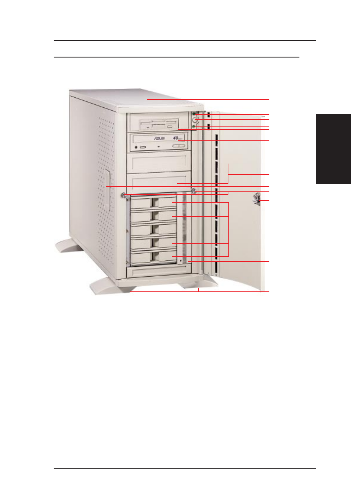
• 2-1. Server Front Side
The front side of the server is provided to show the front exterior components of this server. The chassis is made of strong rust-resistant metal and
covered with a protective ivory surfacing.
1
2
3
4
5
6
Front Side
1. Top Panel
2. Power LED
3. ATX Power Button
4. Hard Drive Access LED
7
8
9
10
11
12
13
II. Components
Server Front Side
5. Floppy Disk Drive
6. CD-ROM Drive
7. Drive Expansion Bay
8. Side Panel Handle
9. Side Panel Screw
10. Metal Door Lock
11. Hot Swap Tray
12. Hard Drive Fan Module
13. Chassis Stabilizers
AP 3000 Hardware Reference Guide
13
 Loading...