


ASUS P2Z-VM User Manual

R
P2Z-VM
Pentium® III / II / CeleronTM Motherboard
USER’S MANUAL

USER'S NOTICE
No part of this manual, including the products and software described in it, may be reproduced, transmitted, transcribed, stored in a retrieval system, or translated into any language
in any form or by any means, except documentation kept by the purchaser for backup purposes, without the express written permission of ASUSTeK COMPUTER INC. (“ASUS”).
ASUS PROVIDES THIS MANUAL “AS IS” WITHOUT WARRANTY OF ANY KIND,
EITHER EXPRESS OR IMPLIED, INCLUDING BUT NOT LIMITED TO THE IMPLIED
W ARRANTIES OR CONDITIONS OF MERCHANTABILITY OR FITNESS FOR A P ARTICULAR PURPOSE. IN NO EVENT SHALL ASUS, ITS DIRECTORS, OFFICERS,
EMPLOYEES OR AGENTS BE LIABLE FOR ANY INDIRECT, SPECIAL, INCIDENTAL, OR CONSEQUENTIAL DAMAGES (INCLUDING DAMAGES FOR LOSS OF
PROFITS, LOSS OF BUSINESS, LOSS OF USE OR DATA, INTERRUPTION OF BUSINESS AND THE LIKE), EVEN IF ASUS HAS BEEN ADVISED OF THE POSSIBILITY
OF SUCH DAMAGES ARISING FROM ANY DEFECT OR ERROR IN THIS MANUAL
OR PRODUCT.
Product warranty or service will not be extended if: (1) the product is repaired, modified or
altered, unless such repair, modification of alteration is authorized in writing by ASUS; or
(2) the serial number of the product is defaced or missing.
Products and corporate names appearing in this manual may or may not be registered trademarks or copyrights of their respective companies, and are used only for identification or
explanation and to the owners’ benefit, without intent to infringe.
• Intel, LANDesk, and Pentium are registered trademarks of Intel Corporation.
• IBM and OS/2 are registered trademarks of International Business Machines.
• Symbios is a registered trademark of Symbios Logic Corporation.
• Windows and MS-DOS are registered trademarks of Microsoft Corporation.
• Adobe and Acrobat are registered trademarks of Adobe Systems Incorporated.
The product name and revision number are both printed on the product itself. Manual revi-
sions are released for each product design represented by the digit before and after the period
of the manual revision number. Manual updates are represented by the third digit in the
manual revision number.
For previous or updated manuals, BIOS, drivers, or product release information, contact ASUS
at http://www.asus.com.tw or through any of the means indicated on the following page.
SPECIFICATIONS AND INFORMATION CONTAINED IN THIS MANUAL ARE FURNISHED FOR INFORMATIONAL USE ONLY, AND ARE SUBJECT TO CHANGE AT
ANY TIME WITHOUT NOTICE, AND SHOULD NOT BE CONSTRUED AS A COMMITMENT BY ASUS. ASUS ASSUMES NO RESPONSIBILITY OR LIABILITY FOR
ANY ERRORS OR INACCURACIES THA T MAY APPEAR IN THIS MANUAL, INCLUDING THE PRODUCTS AND SOFTWARE DESCRIBED IN IT.
Copyright ©1999 ASUSTeK COMPUTER INC. All Rights Reserved.
Product Name: ASUS P2Z-VM
Manual Revision: 1.02 E352
Release Date: March 1999
2
ASUS P2Z-VM User’s Manual

ASUS CONTACT INFORMATION
ASUSTeK COMPUTER INC. (Asia-Pacific)
Marketing
Address: 150 Li-Te Road, Peitou, Taipei, Taiwan 112
Telephone: +886-2-2894-3447
Fax: +886-2-2894-3449
Email: info@asus.com.tw
Technical Support
Tel (English): +886-2-2894-3447 ext. 706
Tel (Chinese): +886-2-2894-3447 ext. 701
Fax: +886-2-2895-9254
Email: tsd@asus.com.tw
Newsgroup: news2.asus.com.tw
WWW: www.asus.com.tw
FTP: ftp.asus.com.tw/pub/ASUS
ASUS COMPUTER INTERNATIONAL (America)
Marketing
Address: 6737 Mowry Avenue, Mowry Business Center, Building 2
Newark, CA 94560, USA
Fax: +1-510-608-4555
Email: info-usa@asus.com.tw
Technical Support
Fax: +1-510-608-4555
BBS: +1-510-739-3774
Email: tsd-usa@asus.com.tw
WWW: www.asus.com
FTP: ftp.asus.com.tw/pub/ASUS
ASUS COMPUTER GmbH (Europe)
Marketing
Address: Harkort Str. 25, 40880 Ratingen, BRD, Germany
Telephone: 49-2102-445011
Fax: 49-2102-442066
Email: sales@asuscom.de
Technical Support
Hotline: 49-2102-499712
BBS: 49-2102-448690
Email: tsd@asuscom.de
WWW: www.asuscom.de
FTP: ftp.asuscom.de/pub/ASUSCOM
ASUS P2Z-VM User’s Manual 3

CONTENTS
I. INTRODUCTION............................................................................... 7
How this Manual is Organized ........................................................... 7
Item Checklist ..................................................................................... 7
II. FEATURES ........................................................................................ 8
Features of the ASUS P2Z-VM Motherboard .................................... 8
The ASUS P2Z-VM Motherboard .............................................. 11
III. HARDWARE SETUP .................................................................... 12
Layout of the ASUS P2Z-VM Motherboard..................................... 12
Hardware Setup Steps ....................................................................... 14
1. Motherboard Settings.................................................................... 14
Jumpers ....................................................................................... 14
2. System Memory (DIMM) ............................................................. 19
DIMM Memory Installation Procedures: .............................. 20
3. Central Processing Unit (CPU).................................................... 21
Universal Retention Mechanism ........................................... 21
Heatsinks ............................................................................... 21
Installing the Processor ............................................................... 22
Recommended Heatsinks for Slot 1 Processors .................... 24
4. Expansion Cards ........................................................................... 25
Expansion Card Installation Procedure ................................. 25
Assigning IRQs for Expansion Cards.................................... 25
Assigning DMA Channels for ISA Cards.............................. 26
Accelerated Graphics Port ..................................................... 26
5. External Connectors..................................................................... 27
Power Connection Procedures .......................................................... 37
IV. BIOS SETUP................................................................................... 38
Flash Memory Writer Utility ............................................................ 38
Main Menu .................................................................................. 38
Managing and Updating Your Motherboard’s BIOS................... 40
6. BIOS Setup .................................................................................. 41
Load Defaults ........................................................................ 42
Standard CMOS Setup ................................................................ 42
Details of Standard CMOS Setup:......................................... 42
BIOS Features Setup ................................................................... 45
Details of BIOS Features Setup............................................. 45
Chipset Features Setup ................................................................ 48
Details of Chipset Features Setup.......................................... 48
4
ASUS P2Z-VM User’s Manual

CONTENTS
Power Management Setup........................................................... 51
Details of Power Management Setup .................................... 51
PNP and PCI Setup ..................................................................... 54
Details of PNP and PCI Setup ............................................... 54
Load BIOS Defaults .................................................................... 56
Load Setup Defaults .................................................................... 56
Supervisor Password and User Password ................................... 57
IDE HDD Auto Detection ........................................................... 58
Save & Exit Setup ....................................................................... 60
Exit Without Saving .................................................................... 60
V. SOFTWARE SETUP ....................................................................... 63
Windows 98 First Time Installation.................................................. 63
P2Z-VM Support CD Autorun Screen.............................................. 64
Installing the Video Driver and Utility ............................................. 65
Installing Audio Utilites.................................................................... 69
Installing the Software Wavetable .................................................... 70
Installing PCCillin ............................................................................ 71
VI. SOFTWARE REFERENCE.......................................................... 73
ATI Player ......................................................................................... 73
Task Control Panel ...................................................................... 73
Audio CD Player ......................................................................... 74
MPEG Player .............................................................................. 75
TV T uner ..................................................................................... 76
Teletext ........................................................................................ 76
Capture ........................................................................................ 77
AudioRack32 .................................................................................... 79
VII. APPENDIX.................................................................................... 87
The ASUS S370 CPU Card .............................................................. 87
ASUS PCI-L101 Fast Ethernet Card ................................................ 89
Glossary ............................................................................................ 91
ASUS P2Z-VM User’s Manual 5

FCC & DOC COMPLIANCE
Federal Communications Commission Statement
This device complies with FCC Rules Part 15. Operation is subject to the following
two conditions:
• This device may not cause harmful interference, and
• This device must accept any interference received, including interference that
may cause undesired operation.
This equipment has been tested and found to comply with the limits for a Class B
digital device, pursuant to Part 15 of the FCC Rules. These limits are designed to
provide reasonable protection against harmful interference in a residential installation. This equipment generates, uses and can radiate radio frequency energy and, if
not installed and used in accordance with manufacturer's instructions, may cause
harmful interference to radio communications. However , there is no guarantee that
interference will not occur in a particular installation. If this equipment does cause
harmful interference to radio or television reception, which can be determined by
turning the equipment off and on, the user is encouraged to try to correct the interference by one or more of the following measures:
• Re-orient or relocate the receiving antenna.
• Increase the separation between the equipment and receiver.
• Connect the equipment to an outlet on a circuit different from that to which
the receiver is connected.
• Consult the dealer or an experienced radio/TV technician for help.
WARNING! The use of shielded cables for connection of the monitor to the
graphics card is required to assure compliance with FCC regulations. Changes
or modifications to this unit not expressly approved by the party responsible for
compliance could void the user's authority to operate this equipment.
Canadian Department of Communications Statement
This digital apparatus does not exceed the Class B limits for radio noise emissions
from digital apparatus set out in the Radio Interference Regulations of the Canadian Department of Communications.
6
ASUS P2Z-VM User’s Manual
I. INTRODUCTION
How this Manual is Organized
This manual is divided into the following sections:
I. Introduction Manual information and checklist
II. Features Information and specifications concerning this product
III. Hardware Setup Instructions on setting up the motherboard and jumpers
IV. BIOS Setup Instructions on setting up the BIOS software
V. Software Setup Instructions on setting up the included support software
VI. Software Reference Reference material for the included support software
VII. Appendix Optional items and general reference
Item Checklist
Please check that your package is complete. If you discover damaged or missing
items, please contact your retailer.
(1) ASUS Motherboard
Manual / Checklist
I. INTRODUCTION
(1) Universal Retention Mechanism for SECC/SECC2/SEPP
(1) Ribbon cable for master and slave IDE drives
(1) Ribbon cable for (1) 5.25” and (2) 3.5” floppy disk drives
(1) COM2 connector with bracket
(1) Bag of spare jumper caps
(1) Support CD with drivers and utilities
(1) This Motherboard User’s Manual
ASUS IrDA-compliant infrared module (optional)
ASUS S370 CPU card (optional)
ASUS PCI-L101 Wake-On-LAN 10/100 Ethernet Card (optional)
ASUS P2Z-VM User’s Manual 7

Features of the ASUS P2Z-VM Motherboard
The ASUS P2Z-VM is carefully designed for the demanding PC user who wants
advanced features processed by the fastest CPU.
Specifications:
• Multi-Speed: Supports Intel Pentium
• Intel AGPset: Features Intel’s 440ZX AGPset with I/O subsystems and front-
II. FEATURES
Specifications
• Multi-Cache: Supports processors with either 512, 128, or 0KB Pipelined Burst
• PC100 Memory Support: Equipped with two DIMM sockets to support Intel
• AGP 3D VGA (optional): Features onboard ATI 3D Rage Pro AGP 2X (8MB
II. FEATURES
®
III (450MHz and faster), Pentium® II
(233MHz to 450MHz), and Celeron
side bus (FSB) platform, which boosts the traditional 66MHz external bus speed
to 100MHz.
Level 2 cache.
PC100-compliant SDRAMs (8, 16, 32, 64, 128, or 256MB) up to 512MB. These
new SDRAMs are necessary to meet the critical enhanced 100MHz bus speed
requirement.
SDRAM) or Rage IIC AGP (4MB SDRAM) for 3D hardware acceleration.
TM
(266MHz and faster) processors.
• Peripheral Wake Up: Supports modem wake up, keyboard wake up, and LAN
card wake up functions from sleep or soft-off mode.
• AGP Slot (optional): Supports an Accelerated Graphics Port card for high per -
formance, component level interconnect targeted at 3D graphical display applications using a 1X or 2X mode bus. This slot is available as an option with Rage
IIC only.
• PCI Audio (optional): Features ESS Solo-1 32-bit PCI audio onboard.
• SB-Link™: Features Creative’s SB-Link™, allowing SB16 compatibility, us-
ing Intel’s PC-PCI DMA and serialized IRQ protocols, to AWE64D or compatible PCI audio cards.
• SMBus: Features the System Management Bus interface, which is used to physi-
cally transport commands and information between SMBus devices.
• PCI & ISA Expansion Slots: Provides three 32-bit PCI slots and one 16-bit
ISA slot.
• Multi-I/O: Provides two high-speed UAR T compatible serial ports and one par-
allel port with EPP and ECP capabilities. UART2 can also be directed from
COM2 to the Infrared Module for wireless connections.
• Ultra DMA/33 Bus Master IDE: Comes with an onboard PCI Bus Master IDE
controller with two connectors that support four IDE devices in two channels,
supports UltraDMA/33, PIO Modes 3 and 4 and Bus Master IDE DMA Mode 2,
and supports Enhanced IDE devices, such as Tape Backup and CD-ROM, and
LS-120 drives.
• Universal Retention Mechanism: Supports a Pentium
®
III / Pentium® II processor packaged in a Single Edge Contact Cartridge (SECC2/SECC) or a
Celeron
TM
processor packaged in a Single Edge Processor Package (SEPP).
8 ASUS P2Z-VM User’s Manual

II. FEATURES
• Wake-On-LAN: Supports Wake-On-LAN activity through an optional ASUS
PCI-L101 10/100 Fast Ethernet PCI card (see APPENDIX) or a similar ethernet
card.
• IrDA: Supports an optional infrared module (see APPENDIX) for a wireless
interface.
Special Features:
• Enhanced ACPI and Anti-Boot V irus BIOS: Features a programmable BIOS,
offering enhanced ACPI for W indows 98 compatibility, built-in firmware-based
virus protection through T rend ChipA way V irus codes, and autodetection of most
devices for virtually automatic setup.
• Desktop Management Interface (DMI): Supports DMI through BIOS, which
allows hardware to communicate within a standard protocol creating a higher
level of compatibility. (Requires DMI-enabled components.)
• Easy Installation: Incorporates BIOS that supports autodetection of hard disk
drives, PS/2 mouse, and Plug and Play devices to make the setup of hard disk
drives, expansion cards, and other devices virtually automatic.
Specifications
II. FEATURES
• PC’98 Compliant: Both the BIOS and hardware levels of ASUS smart series of
motherboards meet PC’98 compliancy. The new PC’98 requirements for systems and components are based on the following high-level goals: Support for
Plug and Play compatibility and power management for configuring and managing all system components, and 32-bit device drivers and installation procedures for Windows 95/98/NT.
• Symbios SCSI BIOS: Supports optional ASUS SCSI controller cards through
onboard SYMBIOS firmware.
Performance Features:
• Concurrent PCI: Concurrent PCI allows multiple PCI transfers from PCI mas-
ter busses to the memory and processor.
• Double the IDE Transfer Speed: This motherboard with its chipset improves
IDE transfer rate using Bus Master UltraDMA/33 IDE which can handle data
transfer up to 33MB/s. The best of all is that this new technology is compatible
with existing A TA-2 IDE specs so there is no need to upgrade current hard drives
or cables.
• SDRAM Optimized Performance: Supports the new generation memory - Syn-
chronous Dynamic Random Access Memory (SDRAM) which increases the data
transfer rate to 800MB/s max using PC100-compliant SDRAM.
ASUS P2Z-VM User’s Manual 9

Intelligent Features:
• Auto Fan Off: The system fans will power off automatically even in sleep
• Dual Function Power Button: Pushing the power button for less than 4 sec-
II. FEATURES
Specifications
• Keyboard Power Up: Keyboard Power Up can be enabled or disabled to allow
• Message LED (requires ACPI OS support): Turbo LEDs now act as informa-
II. FEATURES
mode. This function reduces both energy consumption and system noise, and is
an important feature in implementing silent PC systems.
onds when the system is in the working state places the system into one of two
states: sleep mode or soft-off mode, depending on the BIOS setting (see Power
Management Setup under BIOS SETUP). When the power button is pressed for
more than 4 seconds, the system enters the soft-off mode regardless of the BIOS
setting.
the computer to be powered up using your keyboard.
tion providers. Through the way a particular LED illuminates, the user can determine the stage the computer is in. A simple glimpse provides useful information to the user.
• Remote Ring On (requires external modem): This allows a computer to be
turned on remotely through an external modem. With this benefit on-hand, any
user can access vital information from their computer from anywhere in the world!
• System Resources Alert: Today’s operating systems such as Windows 95/98/
NT and OS/2, require much more memory and hard drive space to present enor mous user interfaces and run large applications. The system resource monitor
will warn the user before the system resources are used up to prevent possible
application crashes. Suggestions will give the user information on managing
their limited resources more efficiently.
10 ASUS P2Z-VM User’s Manual
II. FEATURES
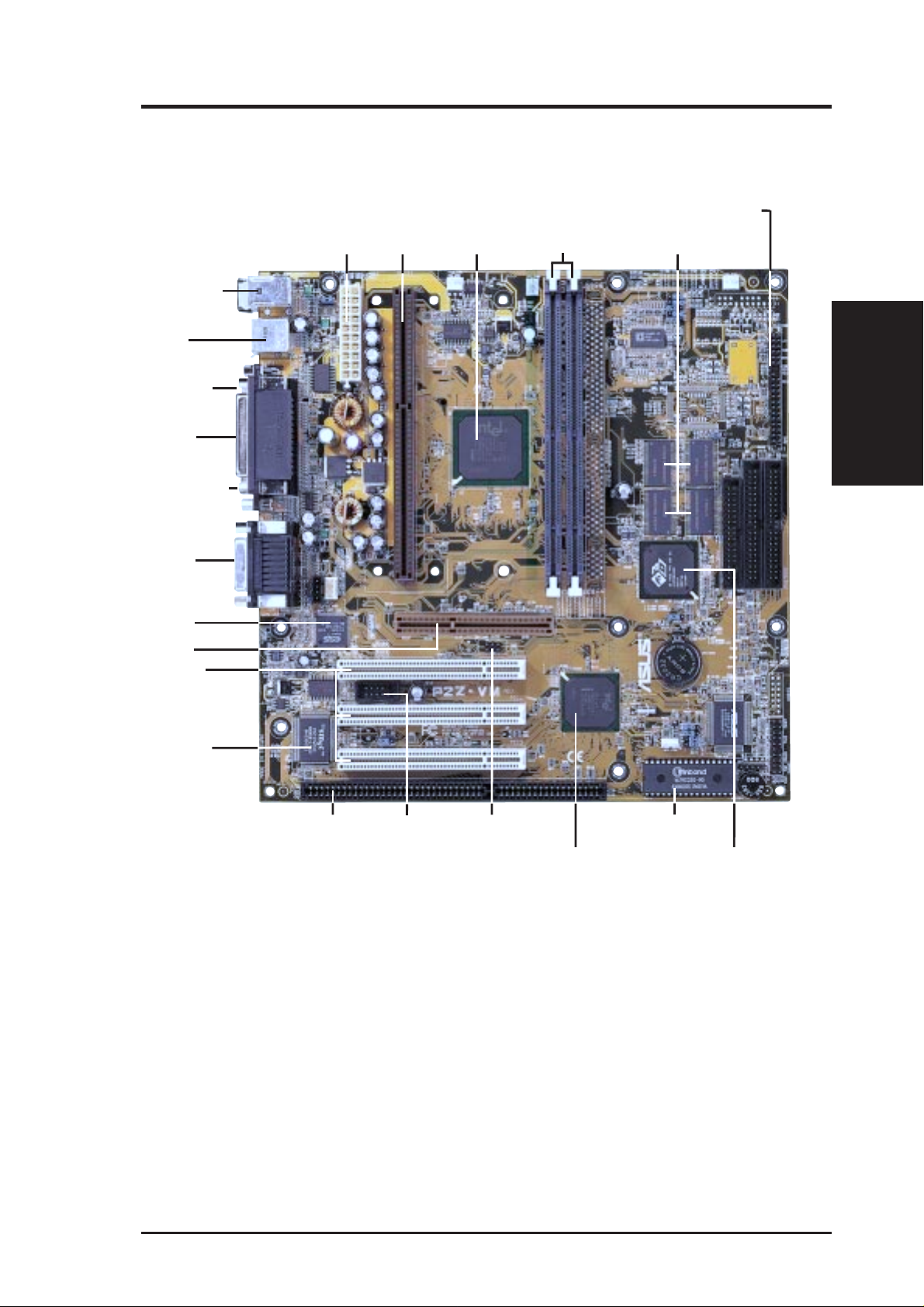
The ASUS P2Z-VM Motherboard
2 DIMM
Sockets
T: PS/2 Mouse
B: PS/2 Keyboard
T: USB1
B:USB2
Serial COM1
ATX Power
Slot 1
Intel 440ZX
AGPset
ATI Multimedia Connector
4MB VGA Memory (Rage IIC)
8MB VGA Memory (Rage Pro)
T: Parallel
B:Serial/VGA
VGA Connector
T: Joystick/Midi
B: Out/In/Mic
(optional)
ESS Solo-1
3D PCI Audio
(optional)
AGP Port
(optional)
3 PCI Slots
Multi-I/O
& Keyboard
Controller
1 ISA Slot Programmable
Serial COM2
Header
SB-Link™
Connector
Intel PIIX4E
PCIset
Flash EEPROM
ATI 3D Rage Pro AGP 2X
ATI 3D Rage IIC AGP
II. FEATURES
Motherboard Parts
ASUS P2Z-VM User’s Manual 11
III. HARDWARE SETUP
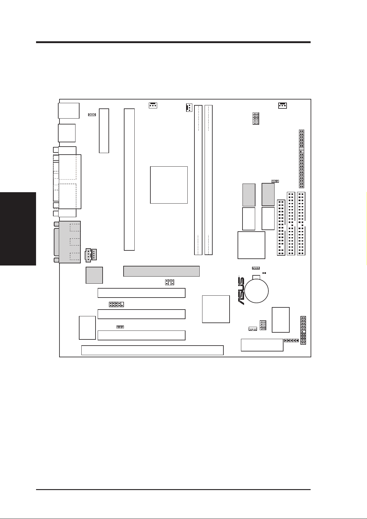
Layout of the ASUS P2Z-VM Motherboard
T:
PS/2
USB
COM1
Mouse
B:
Keyboard
KB_WAK
T: USB 1
B: USB 2
ATXPWR
PWR_FAN
PS_FAN
CPU_FAN
BUS FREQ
FS0
FS1
FS2
FS3
FS4
CHA_FAN
AMC
Motherboard Layout
PARALLEL PORT
III. H/W SETUP
VGA
(optional)
GAME/AUDIO
Line
Out
In
Line
In
Mic
Keyboard
Controller
CD_IN
32-bit PCI
Chipset
Multi-I/O
&
Audio
COM2
MODEM_IN
Slot 1
Intel
440ZX
AGPset
Accelerated Graphics Port
SB-LINK
PCI Slot 1 (PCI1)
P2Z-VM
PCI Slot 2 (PCI2)
AUDIO_EN
PCI Slot 3 (PCI3)
ISA Slot 1 (ISA1)
8MB available on
Rage Pro only
SDRAM
SDRAM
VGAEN
2 MB
2 MB
CLRTC
2 MB
2 MB
DIMM Socket 2 (64/72 bit, 168 pin module)
DIMM Socket 1 (64/72 bit, 168 pin module)
ATI 3D Rage
Pro AGP 2X/
Row
01 23
IIC AGP
VGA Chipset
R
CR2032 3V
Lithium Cell
(CMOSPower)
Intel
PIIX4E
PCIset
FREQ MULT
WOL_CON
2Mbit Flash EEPROM
(Programable BIOS)
BF0
BF1
BF2
BF3
SDRAM
SDRAM
ASUS
ASIC
INT_EN
FLOPPY
SECONDARY IDE
IR
ATI Multimedia Connector
PRIMARY IDE
Panel Connectors
(Grayed items are optional at the time of purchase.)
12 ASUS P2Z-VM User’s Manual

III. HARDWARE SETUP
Jumpers
1) INT_EN p. 14 VGA Interrupt Setting (Enable/Disable)
2) VGAEN p. 15 VGA Setting (Enable/Disable)
3) KB_WAK p. 15 Keyboard Power (Wake) Up (Enable/Disable)
4) AUDIO_EN p. 16 Audio Setting (Enable/Disable)
5) FS0, FS1, FS2, FS3, FS4 p. 16 CPU External Clock (BUS) Frequency Selection
6) BF0, BF1, BF2, BF3 p. 17 CPU:BUS Frequency Multiple
Expansion Slots
1) DIMM1, DIMM2 p. 19 168-Pin DIMM Memory Support
2) Slot1 p. 21 CPU Support
3) PCI1, PCI2, PCI3 p. 25 32-bit PCI Bus Expansion Slots
4) ISA1 p. 25 16-bit ISA Bus Expansion Slot
Connectors
1) PS2KBMS P. 27 PS/2 Mouse Connector (6-pin female)
2) PS2KBMS p. 27 PS/2 Keyboard Connector (6-pin female)
3) PRINTER p. 28 Parallel Port Connector (25-pin female)
4) COM1 p. 28 Serial Port COM1 Connector (9-pin male)
5) VGA p. 28 Monitor (VGA) Output Connector (15-pin female)
6) GAME_AUDIO p. 29 Audio Port Connectors (Three 1/8” female) (optional)
7) GAME_AUDIO p. 29 Joystick/Midi Connector (15-pin female) (optional)
8) USB p. 29 Universal Serial BUS Ports 1 & 2 (T wo 4-pin female)
9) PRIMARY/SECONDARY IDEp. 30 Primary/Secondary IDE Connectors (Two 40-1pins)
10) FLOPPY p. 30 Floppy Disk Drive Connector (34-1pins)
11) IR p. 31 IrDA-Compliant Infrared Module Connector (5 pins)
12) WOL_CON p. 31 Wake-On-LAN Connector (3 pins)
13) CHA_, CPU_, PWR_FAN p. 32 Chassis, CPU, Power Supply Fan Connectors (Three 3-pin)
14) SB-LINK p. 32 SB-LinkTM Connector (6-1 pins)
15) CD_IN, MODEM_IN p. 33 Internal Audio Connectors (Two 4-pin)
16) COM2 p. 33 Serial Port COM2 Header (10-1 pins)
17) MLED (PANEL) p. 34 System Message LED (2 pins)
18)
KEYLOCK (
19) SMI (PANEL) p. 34 SMI Switch Lead (2 pins)
20) SPEAKER (PANEL) p. 34 Speaker Output Connector (4 pins)
21) PWR (PANEL) p. 34 ATX Power & Soft-Off Switch Lead (2 pins)
22) IDELED (PANEL) p. 34 IDE Activity LED (2 pins)
23)
PLED (
24) RESET (PANEL) p. 34 Reset Switch Lead (2 pins)
25) AMC p. 35 ATI Multimedia Channel Connector (40-3 pins)
26) ATXPWR p. 35 ATX Power Supply Connector (20 pins)
PANEL
PANEL
)
)
p. 34 Keyboard Lock Switch Lead (2 pins)
p. 34 System Power LED Lead (3-1 pins)
III. H/W SETUP
Layout Contents
ASUS P2Z-VM User’s Manual 13
Hardware Setup Steps
Before using your computer, you must complete the following steps:
1. Check Motherboard Settings
2. Install Memory Modules
3. Install the Central Processing Unit (CPU)
4. Install Expansion Cards
5. Connect Ribbon Cables, Panel Wires, and Power Supply
6. Setup the BIOS Software
1. Motherboard Settings
This section explains in detail how to change your motherboard’s function settings
through the use of switches and/or jumpers.
WARNING! Computer motherboards and expansion cards contain very delicate
Motherboard Settings
III. H/W SETUP
Integrated Circuit (IC) chips. To protect them against damage from static electricity, you should follow some precautions whenever you work on your computer.
III. HARDWARE SETUP
1. Unplug your computer when working on the inside.
2. Use a grounded wrist strap before handling computer components. If you do
not have one, touch both of your hands to a safely grounded object or to a
metal object, such as the power supply case.
3. Hold components by the edges and try not to touch the IC chips, leads or
connectors, or other components.
4. Place components on a grounded antistatic pad or on the bag that came with
the component whenever the components are separated from the system.
Jumpers
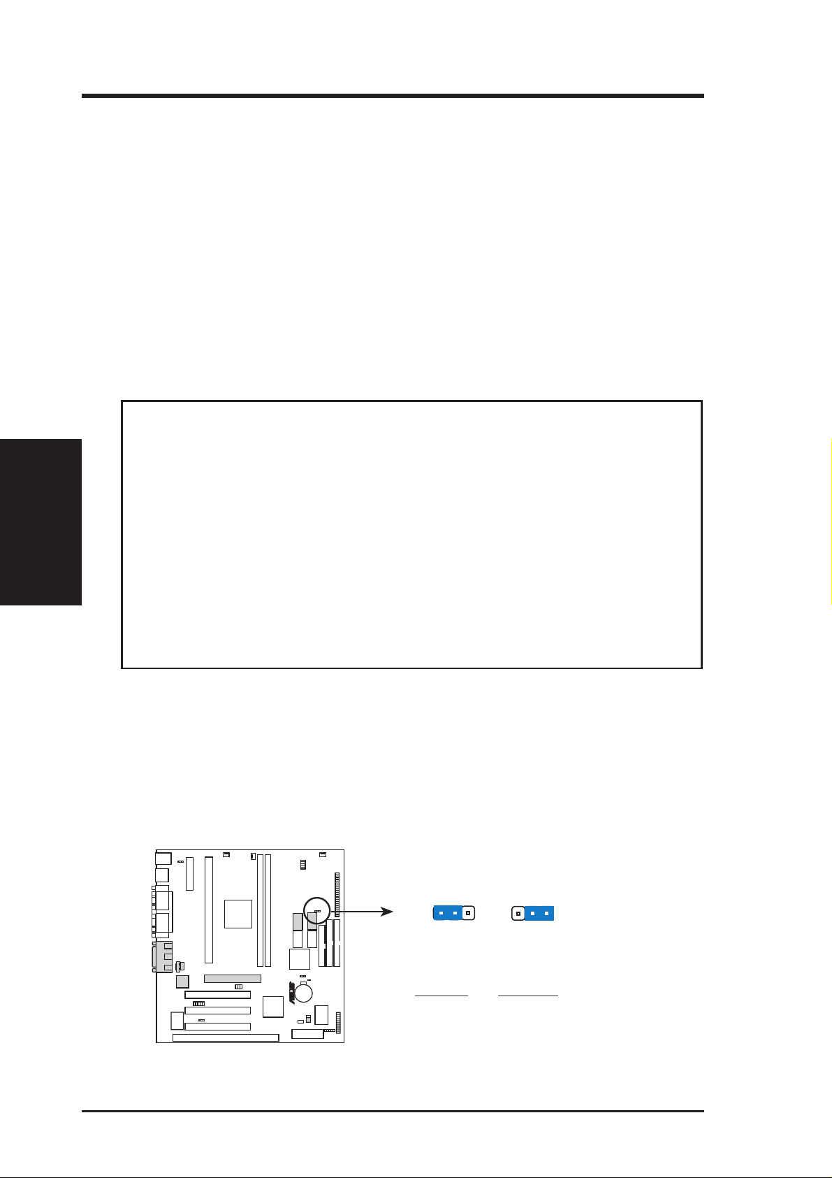
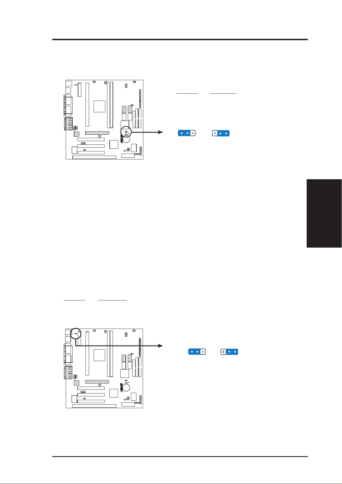
1. VGA Interrupt Selection (INT_EN)
The INT_EN jumper allows you to set the VGA interrupt method. The default disables the chipset’ s internal interrupt routing. Some TV-Tuner or MPEG cards may
require that the interrupt be assigned by the onboard chipset, in which case enable
INT_EN.
INT_EN
123
123
P2Z-VM
Disable
(Default)
R
Setting INT EN
Disable [1-2] (default)
Enable
Enable [2-3]
P2Z-VM VGA Interrupt Setting
14 ASUS P2Z-VM User’s Manual
III. HARDWARE SETUP
2. VGA Setting (VGAEN)
The VGAEN jumper allows you to enable or disable the onboard VGA. Disable the
onboard VGA if you are using a VGA card on the expansion slot.
Setting VGAEN
Enable [1-2] (default)
Disable [2-3]
VGAEN
R
123
P2Z-VM
(Default)
P2Z-VM VGA Setting
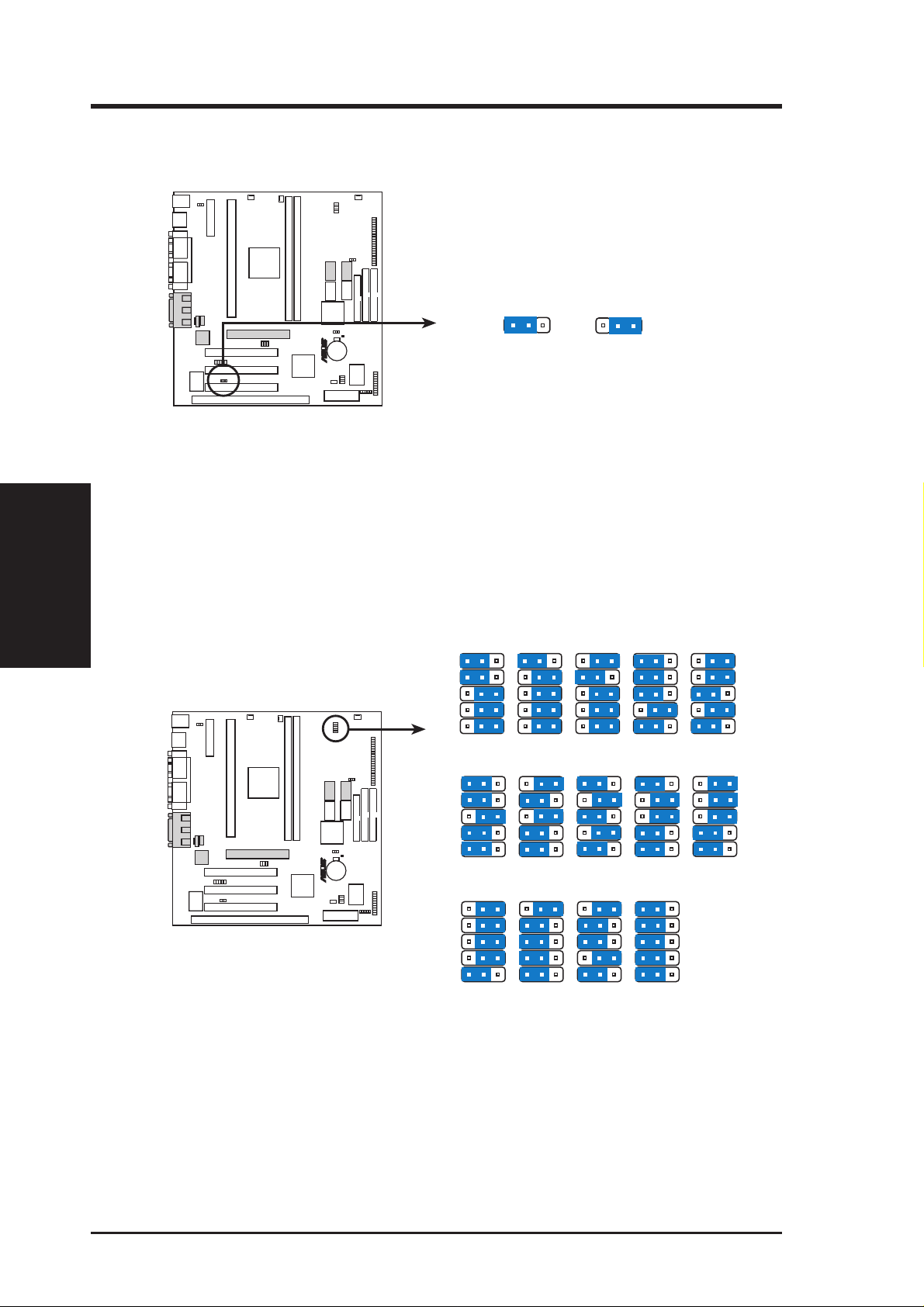
3. Keyboard Power (Wake) Up (KB_WAK)
This allows you to disable or enable the keyboard power up function. Set this
jumper to Enable if you wish to use your keyboard (by pressing any key or the
spacebar, depending on your motherboard) to power up your computer. This
feature requires an ATX power supply that can supply at least 300mA on the
+5VSB lead. The default is set to Disable because not all computers have the
appropriate ATX power supply. Your computer will not power ON if you set this
to Enable and do not have the appropriate ATX power supply. WARNING!
This jumper setting must coincide with the BIOS setting (see “Power Up By
Keyboard” in the Power Management Setup of BIOS SETUP) or else conflicts
will occur.
123
DisableEnable
III. H/W SETUP
Motherboard Settings
Setting KB WAK
Disable [1-2] (default)
Enable [2-3]
R
P2Z-VM
P2Z-VM Keyboard Power (Wake) Up
KB_WAK
123
Disable
(Default)
123
Enable
ASUS P2Z-VM User’s Manual 15
III. HARDWARE SETUP
4. Audio Setting (AUDIO_EN)
The onboard 32-bit PCI audio may be enabled or disabled using this jumper.
AUDIO_EN
R
P2Z-VM
P2Z-VM Audio Setting
123
Enable
(Default)
123
Disable
Motherboard Settings
III. H/W SETUP
5. CPU Bus Frequency Selection (FS0, FS1, FS2, FS3, FS4)
This option tells the clock generator what frequency to send to the CPU, DRAM,
and AGPset. This allows the selection of the CPU’s External frequency (or BUS
Clock). The BUS Clock multiplied by the BUS Ratio equals the CPU’ s Internal
frequency (the advertised CPU speed).
P2Z-VM CPU External Clock
(Bus) Frequency Selection
P2Z-VM
123 123 123 123 123
FS0
FS1
FS2
FS3
FS4
CPU
66.8MHz
PCI
33.4MHz
123 123
FS0
FS1
FS2
FS3
R
FS4
105.0MHz
CPU
35.0MHz
PCI
123 123 123 123
FS0
FS1
FS2
FS3
FS4
124.0MHz
CPU
41.3MHz
PCI
75.0MHz
37.5MHz
110.0MHz
36.7MHz
124.0MHz
31.0MHz
83.0MHz
41.6MHz
123 123 123
112.0MHz
37.3MHz
133.0MHz
44.3MHz
100.3MHz
33.4MHz
115.0MHz
38.3MHz
133.0MHz
33.3MHz
103MHz
34.3MHz
120.0MHz
40.0MHz
16 ASUS P2Z-VM User’s Manual
III. HARDWARE SETUP
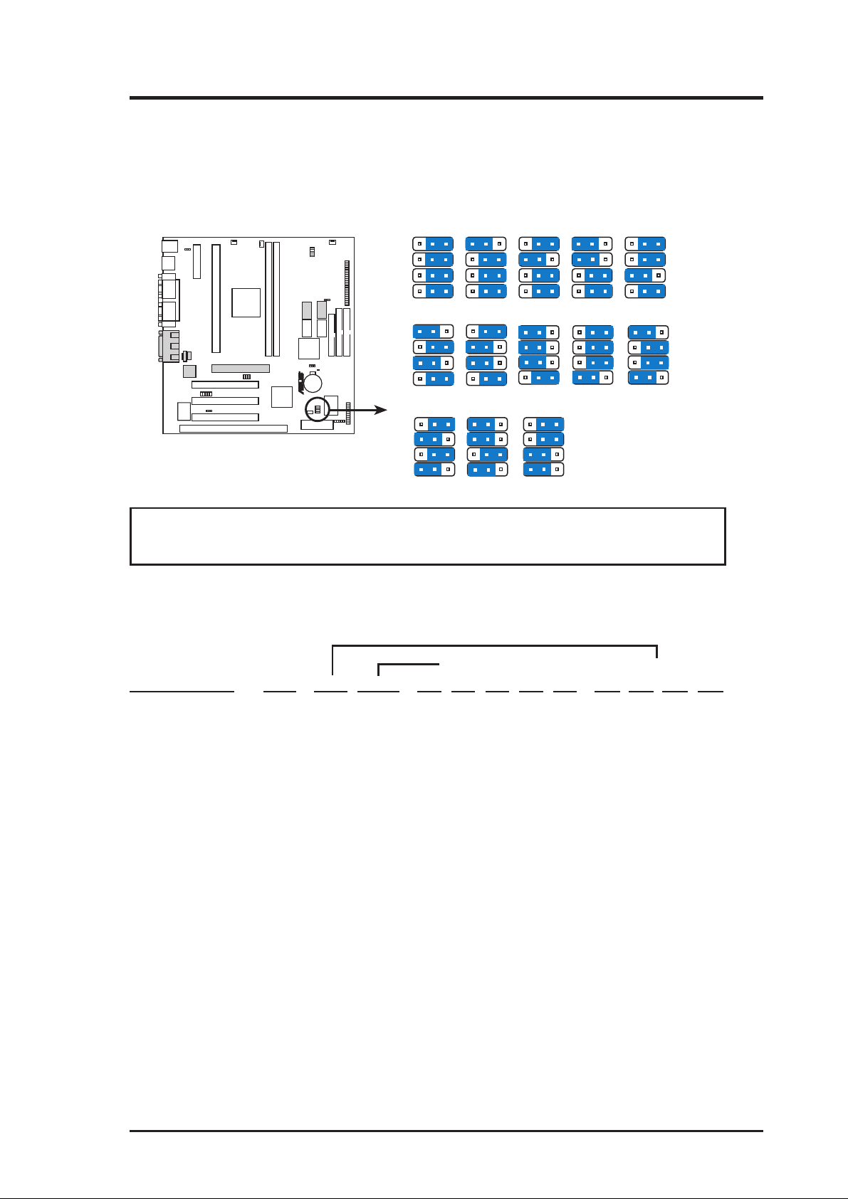
6. CPU Core:BUS Frequency Multiple (BF0, BF1, BF2, BF3)
This option sets the frequency multiple between the Internal frequency of the
CPU and the CPU’ s External frequency . These must be set in conjunction with the
CPU Bus Frequency.
123 123 123 123 123
BF0
BF1
BF2
R
P2Z-VM
P2Z-VM CPU Core : Bus
Frequency Multiple
BF3
123 123
BF0
BF1
BF2
BF3
5.0x(5/1)4.5x(9/2)
123 123 123
BF0
BF1
BF2
BF3
7.0x(7/1) 7.5x(15/2) 8.0x(8/1)
123 123 123
4.0x(4/1)2.0x(2/1) 2.5x(5/2) 3.0x(3/1) 3.5x(7/2)
6.5x(13/2)6.0x(6/1)5.5x(11/2)
WARNING! Frequencies above 1 00MHz exceed the specifications for the on-
board Intel Chipset and are not guaranteed to be stable.
Set the jumpers by the Internal speed of your processor as follows:
(CPU BUS Freq.) (Freq. Multiple)
Intel CPU Model Freq. Ratio BUS F. FS0 FS1 FS2 FS3 FS4 BF0 BF1 BF2 BF3
Pentium III 500MHz 5.0x 100MHz [1-2] [1-2] [1-2] [2-3] [1-2] [2-3] [1-2] [1-2] [2-3]
Pentium III/II 450MHz 4.5x 100MHz [1-2] [1-2] [1-2] [2-3] [1-2] [1-2] [2-3] [1-2] [2-3]
Pentium II/Celeron 400MHz 4.0x 100MHz [1-2] [1-2] [1-2] [2-3] [1-2] [2-3] [2-3] [1-2] [2-3]
Pentium II 350MHz 3.5x 100MHz [1-2] [1-2] [1-2] [2-3] [1-2] [1-2] [1-2] [2-3] [2-3]
Celeron 466MHz 7.0x 66MHz [1-2] [1-2] [2-3] [2-3] [2-3] [2-3] [1-2] [2-3] [1-2]
Pentium II/Celeron 433MHz 6.5x 66MHz [1-2] [1-2] [2-3] [2-3] [2-3] [1-2] [2-3] [2-3] [1-2]
Celeron 400MHz 6.0x 66MHz [1-2] [1-2] [2-3] [2-3] [2-3] [2-3] [2-3] [2-3] [1-2]
Pentium II/Celeron 366MHz 5.5x 66MHz [1-2] [1-2] [2-3] [2-3] [2-3] [1-2] [1-2] [1-2] [2-3]
Pentium II/Celeron 333MHz 5.0x 66MHz [1-2] [1-2] [2-3] [2-3] [2-3] [2-3] [1-2] [1-2] [2-3]
Pentium II/Celeron 300MHz 4.5x 66MHz [1-2] [1-2] [2-3] [2-3] [2-3] [1-2] [2-3] [1-2] [2-3]
Pentium II/Celeron 266MHz 4.0x 66MHz [1-2] [1-2] [2-3] [2-3] [2-3] [2-3] [2-3] [1-2] [2-3]
Pentium II 233MHz 3.5x 66MHz [1-2] [1-2] [2-3] [2-3] [2-3] [1-2] [1-2] [2-3] [2-3]
NOTES: Overclocking your processor is not recommended. It may result in a slower
speed. Voltage Regulator Output Selection (VID) is not needed for the Pentium III/
II/Celeron processor because it sends a VID signal directly to the onboard power
controller.
ASUS P2Z-VM User’s Manual 17

(This page was intentionally left blank.)
Motherboard Settings
III. H/W SETUP
III. HARDWARE SETUP
18 ASUS P2Z-VM User’s Manual
III. HARDWARE SETUP
2. System Memory (DIMM)
NOTE: No hardware or BIOS setup is required after adding or removing memory.
This motherboard uses only Dual Inline Memory Modules (DIMMs). Sockets are
available for 3.3Volt (power level) unbuffered Synchronous Dynamic Random Ac-
cess Memory (SDRAM) of either 8, 16, 32, 64, 128MB, or 256MB.
The Intel 440ZX AGPset does not support ECC function. ECC memory modules
may be used but the ECC function will not be available.
Memory speed setup is recommended through SDRAM Configuration under “Chipset
Features Setup” in BIOS SETUP.
Install memory in any combination as follows:
DIMM Location 168-pin DIMM Size Total Memory
Socket 1 (Rows 0&1) SDRAM 8, 16, 32, 64, 128, 256MB x1
Socket 2 (Rows 2&3) SDRAM 8, 16, 32, 64, 128, 256MB x1
Total System Memory (Max 512MB) =
General DIMM Notes
• For the system CPU bus to operate at 100MHz, use only PC100-compliant
DIMMs. When this motherboard operates at 100MHz, most system will not
even boot if non-compliant modules are used because of the strict timing issues
involved under this speed. If your DIMMs are not PC100-compliant, set the
CPU bus frequency to 66MHz RAM to ensure system stability.
• ASUS motherboards support SPD (Serial Presence Detect) DIMMs. The is the
memory of choice for best performance vs. stability.
• Two possible memory chips are supported: SDRAM with and without ECC.
• SDRAM chips are generally thinner with higher pin density than EDO (Extended Data Output) chips.
• BIOS shows SDRAM memory on bootup screen.
• 8 chips/side modules do not support ECC, only 9 chips/side modules support ECC.
• Single-sided DIMMs come in 16, 32, 64,128MB; double-sided come in 32, 64,
128, 256MB.
III. H/W SETUP
System Memory
ASUS P2Z-VM User’s Manual 19
III. HARDWARE SETUP
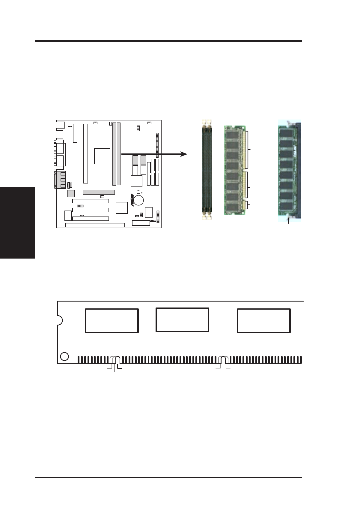
DIMM Memory Installation Procedures:
Insert the module(s) as shown. Because the number of pins are different on either
side of the breaks, the module will only fit in the orientation as shown. DRAM
SIMM modules have the same pin contacts on both sides. SDRAM DIMMs have
different pin contacts on each side and therefore have a higher pin density.
88 Pins
System Memory
III. H/W SETUP
P2Z-VM 168-Pin DIMM Sockets
The DIMMs must be 3.3Volt unbuffered SDRAMs. To determine the DIMM type,
check the notches on the DIMMs (see figure below).
168-Pin DIMM Notch Key Definitions (3.3V)
R
P2Z-VM
DRAM Key Position
60 Pins
20 Pins
Lock
Voltage Key Position
RFU
Buffered
Unbuffered
5.0V
Reserved
3.3V
The notches on the DIMM will shift between left, center, or right to identify the type
and also to prevent the wrong type from being inserted into the DIMM slot on the
motherboard. You must tell your retailer the correct DIMM type before purchasing.
This motherboard supports four clock signals per DIMM.
20 ASUS P2Z-VM User’s Manual
III. HARDWARE SETUP
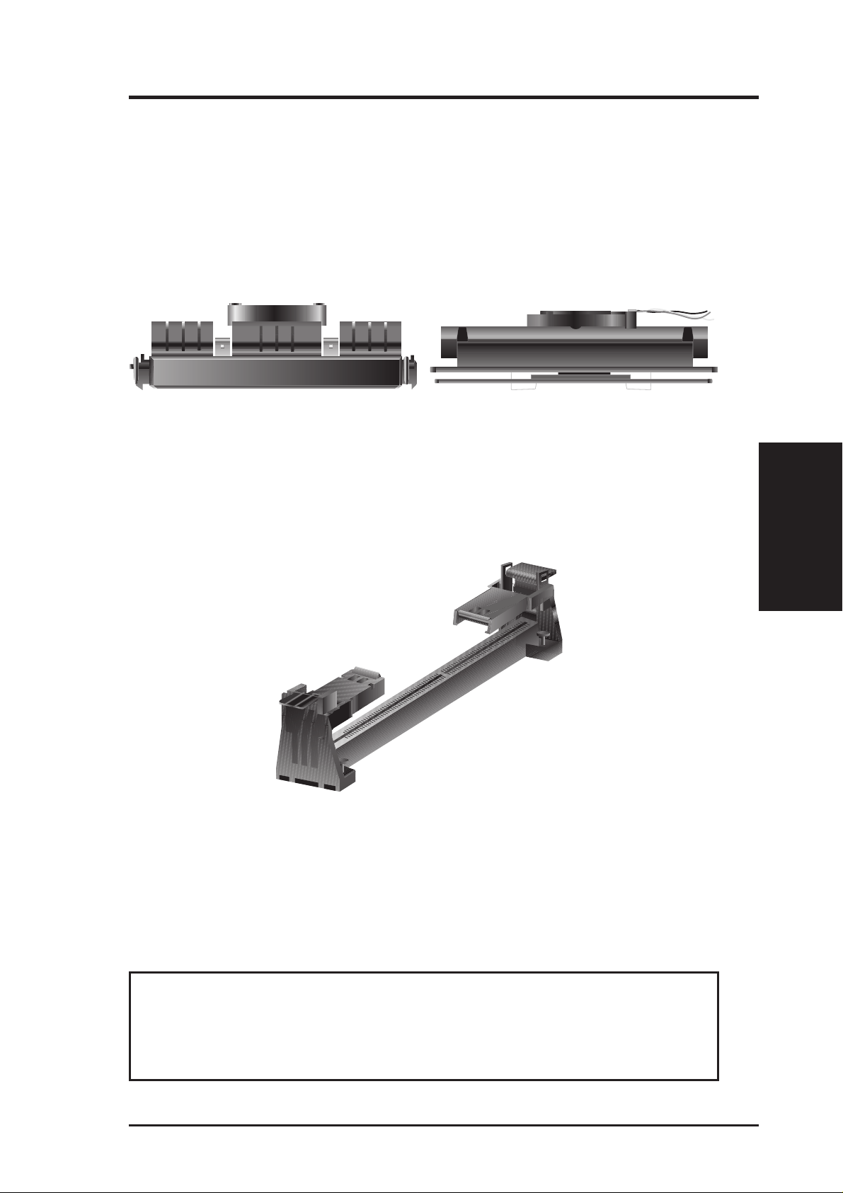
3. Central Processing Unit (CPU)
Your motherboard provides a Slot 1 connector for a Pentium
aged in a Single Edge Contact Cartridge (SECC2), a Pentium
®
III processor pack-
®
II processor packaged in (SECC/SECC2), or a Celeron™ processor packaged in a Single Edge Processor Package (SEPP). An ASUS S370 CPU card can allow Socket 370 processors
to be used on the Slot 1 connector (See ASUS S370 CPU Card in APPENDIX for
instructions on using this card).
Pentium II processor packaged in an SECC with heatsink and
fan (top view)
Pentium III / II processor packaged in an SECC2 or Celeron™
processor packaged in an SEPP with heatsink and fan (top view)
Universal Retention Mechanism
Y our motherboard comes preinstalled with a Universal Retention Mechanism (URM).
The URM supports Pentium III / II and Celeron processors.
CPU
Universal Retention Mechanism (URM)
Heatsinks
The recommended heatsinks (see section on recommended heatsinks for Pentium
III / II processors for more information) for the boxed Pentium III / II and Celeron
processors are those with three-pin fans that can be connected to the fan connectors
on the motherboard.
III. H/W SETUP
WARNING! Be sure that there is suf ficient air circulation across the processor’s
heatsink by regularly checking that your CPU fan is working. W ithout sufficient
circulation, the processor could overheat and damage both the processor and the
motherboard. You may install an auxiliary fan, if necessary.
ASUS P2Z-VM User’s Manual 21
III. HARDWARE SETUP
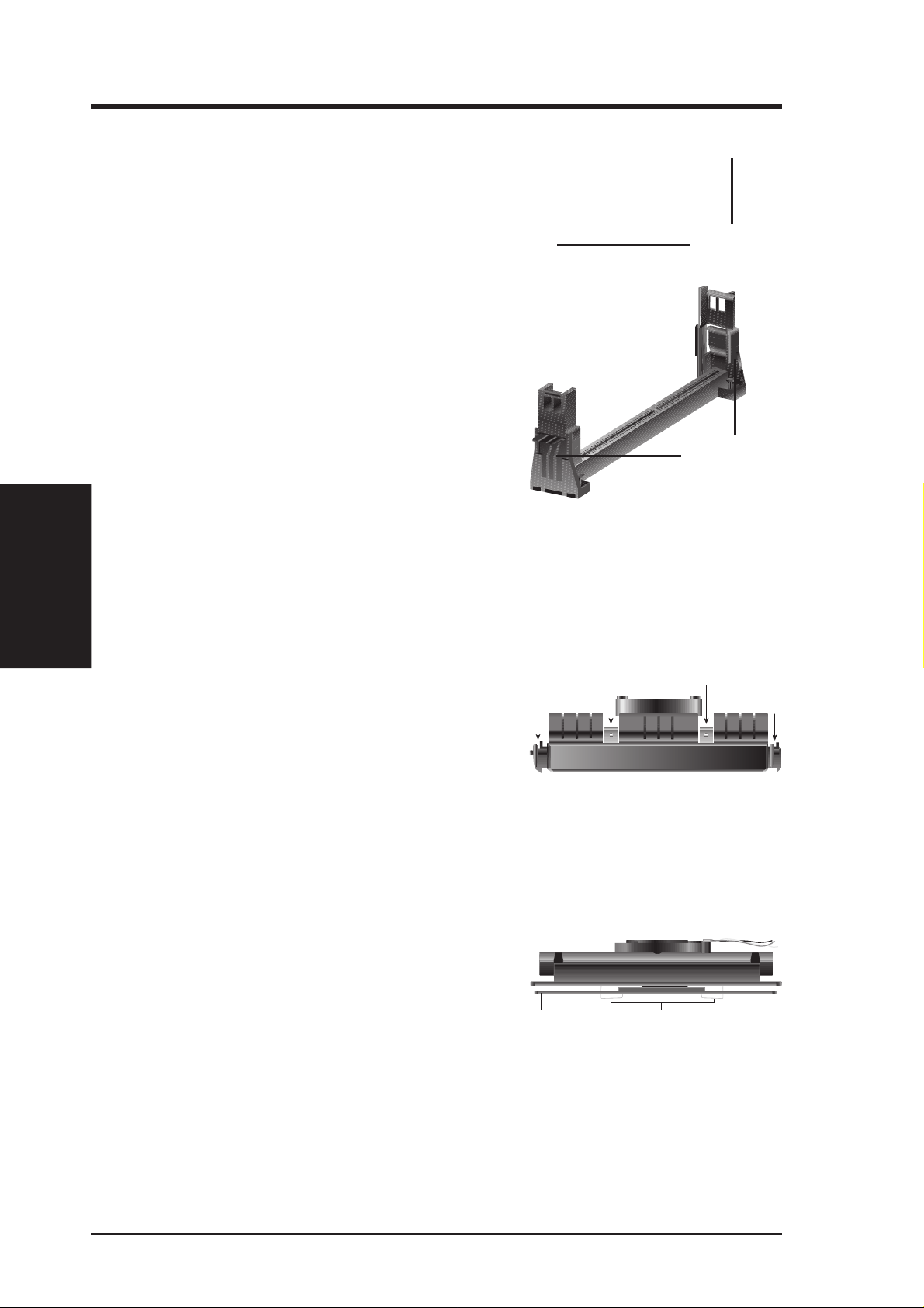
Installing the Processor
1. Unlock the URM’s Folding Support Arms:
The folding support arms of the URM are
locked when shipped.
T o unlock the support arms, simply flip them
up to an upright position.
Locked Folding
Support Arms
III. H/W SETUP
CPU
The URM is now ready for the installation
of your processor.
Unlocked Folding
Support Arms
2. Attach the Heatsink
NOTE: Follow carefully the heatsink attachment instructions included with your
heatsink or processor. The following steps are provided only as a general guide
and may not reflect those for your heatsink.
®
SECC with Pentium
Place the SECC face down on a flat surface
and lay the heat sink flush on the back (metal
II
Push each end of the clamps until they lock
Lock Lock
side) of the SECC. Check the orientation of
the heatsink against the illustration below.
The thicker fin must be orientated toward the
bottom. The top clamp is wider than the bottom clamp so only this orientation
will fit. With a screw driver, push the clamps one at a time into the SECC. Be
sure that the heatsink is firmly pressed against the SECC.
®
SECC2 with Pentium
III / II and SEPP with Celeron™
Insert the heatsink clip through the holes at
the SECC2/SEPP’ s back, making sure that the
bottom of the clip plate sits against the
processors’s back. Remove the tab from the
thermal grease, which is located on the bot-
SECC2/SEPP Heatsink Clip Legs
tom of the heatsink) and place the heatsink over the processor. A slight rocking
motion may be necessary to place the heatsink on the SECC2/SEPP, with one
pair of the heatsink clip legs going first through the corresponding heatsink holes,
and then the other pair . (NOTE: The heatsink and SECC2/SEPP holes are slightly
offset to ensure good locking grip between the two.)
22 ASUS P2Z-VM User’s Manual
III. HARDWARE SETUP
WARNING! Make sure the heatsink is mounted tightly against the SECC, SECC2
or SEPP; otherwise, the CPU will overheat. You may install an auxiliary fan to
provide adequate circulation across the processor’s passive heatsink.
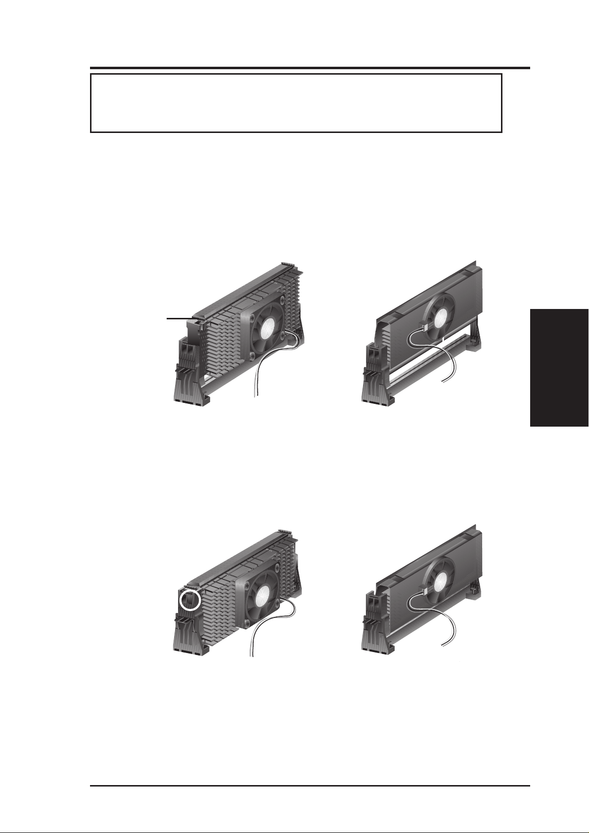
3. Insert the SECC/SECC2/SEPP
SECC with Pentium
®
II only: Push the SECC’s two locks inward until you hear
a click (the picture in step 2 shows the locks in the outward position and inward in
the picture below).
With the heatsink facing the motherboard’s chipset, push the SECC, SECC2, or
SEPP gently but firmly into the Slot 1 connector until it is fully inserted.
SECC
Push lock inward
CPU fan cable to
fan connector
SECC2/SEPP
CPU fan cable to
fan connector
4. Secure the SECC/SECC2/SEPP
Secure the SECC/SECC2/SEPP in place by pushing the SECC/SECC2/SEPP
until it is firmly seated on the Slot 1 connector.
CPU
III. H/W SETUP
SECC with Pentium
®
II only: The SECC locks should be outward when se-
cured so that the lock shows through the retention mechanism’s lock holes.
SECC SECC2/SEPP
Lock hole
CPU fan
CPU fan cable to
fan connector
cable to fan
connector
ASUS P2Z-VM User’s Manual 23
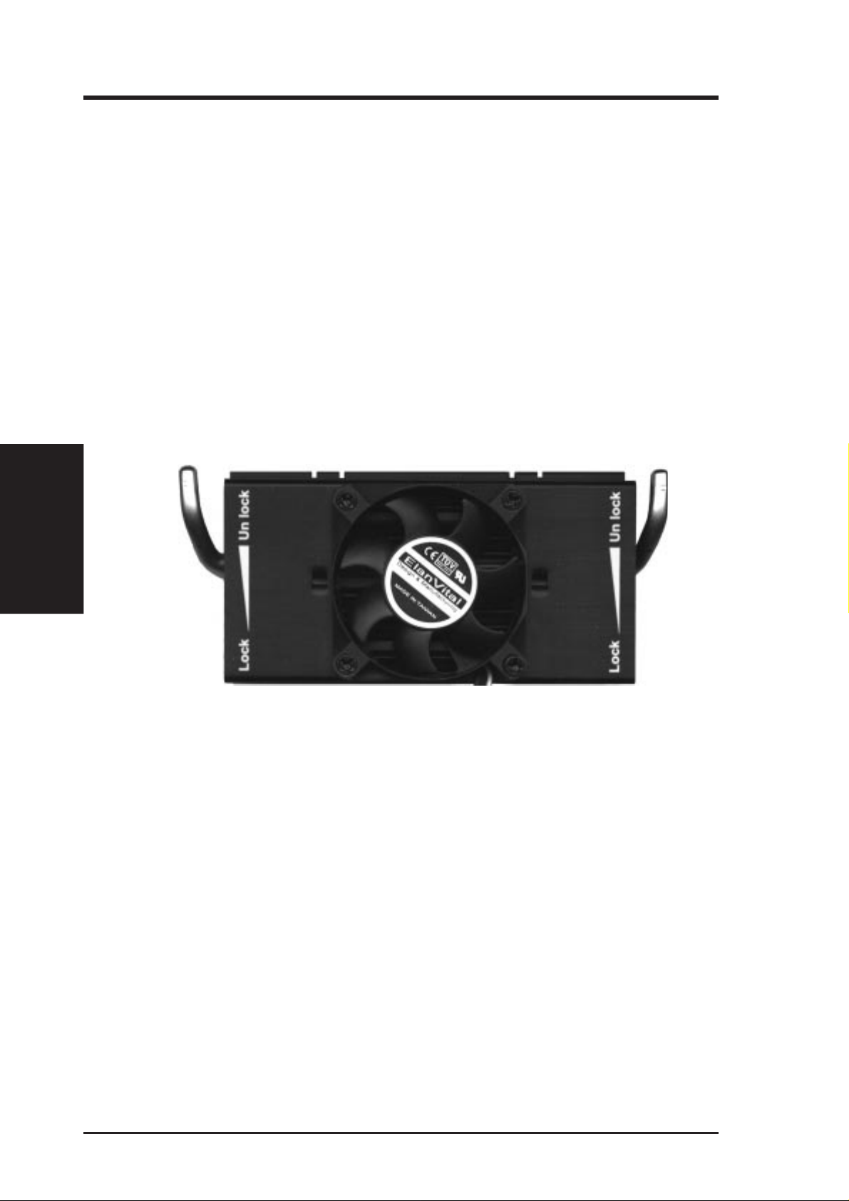
Recommended Heatsinks for Slot 1 Processors
The recommended heatsinks for the Slot 1 processors are those with three-pin fans,
such as the ASUS Smart Fan, that can be connected to the motherboard’s CPU fan
connector. These heatsinks, such as the Elan Vital Heatsink with Fan, dissipate heat
more efficiently and with an optional hardware monitor, they can monitor the fan’s
RPM and use the alert function with the Intel LANDesk Client Manager (LDCM)
and the ASUS PC Probe software.
Elan Vital Heatsink with Fan
To install, simply follow the procedures for Installing the Processor. The Elan V ital heatsink, however, comes with a lever to clamp the heatsink into the SEC cartridge. Mount the heatsink in the orientation as shown then flip the lever from “Unlock” to “Lock.”
III. H/W SETUP
III. HARDWARE SETUP
CPU
24 ASUS P2Z-VM User’s Manual

III. HARDWARE SETUP
4. Expansion Cards
WARNING! Unplug your power supply when adding or removing expansion
cards or other system components. Failure to do so may cause severe damage to
both your motherboard and expansion cards.
Expansion Card Installation Procedure
1. Read the documentation for your expansion card and make any necessary hardware or software settings for your expansion card, such as jumpers.
2. Remove your computer system’s cover and the bracket plate on the slot you
intend to use. Keep the bracket for possible future use.
3. Carefully align the card’s connectors and press firmly.
4. Secure the card on the slot with the screw you removed above.
5. Replace the computer system’s cover.
6. Set up the BIOS if necessary
(such as IRQ xx Used By ISA: Yes in PNP AND PCI SETUP)
7. Install the necessary software drivers for your expansion card.
Assigning IRQs for Expansion Cards
Some expansion cards need to use an IRQ to operate. Generally, an IRQ must be
exclusively assigned to one use. In a standard design, there are 16 IRQs available
but most of them are already in use, leaving 6 IRQs free for expansion cards. If your
motherboard has PCI audio onboard, an extra IRQ will be used, leaving 5 IRQs
free. If your motherboard has ISA audio onboard, an extra 3 IRQs will be used,
leaving 3 IRQs free.
Both ISA and PCI expansion cards may require the use IRQs. System IRQs are
available to cards installed in the ISA expansion bus first, then any remaining IRQs
are available to PCI cards. Currently, there are two types of ISA cards. The original
ISA expansion card design, now referred to as legacy ISA cards, requires that you
configure the card’ s jumpers manually and then install it in any available slot on the
ISA bus. You may use the Microsoft Diagnostics (MSD.EXE) utility located in the
Windows directory to see a map of your used and free IRQs. If you use Windows 95,
the Resources tab under Device Manager displays the resource settings being used
by a particular device (to gain access, double-click the System icon under the Con-
trol Panel program). Ensure that no two devices share the same IRQs or your computer will experience problems when those two devices are in use at the same time.
III. H/W SETUP
Expansion Cards
ASUS P2Z-VM User’s Manual 25
III. HARDWARE SETUP
T o simplify this process this motherboard has complied with the Plug and Play (PNP)
specification which was developed to allow automatic system configuration whenever a PNP-compliant card is added to the system. For PNP cards, IRQs are assigned automatically from those available.
If the system has both Legacy and PNP ISA cards installed, IRQs are
assigned to PNP cards from those not used by Legacy cards. The PCI and PNP
configuration of the BIOS setup utility can be used to indicate which IRQs are being
used by Legacy cards. For older Legacy cards that does not work with the BIOS,
you can contact your vendor for an ISA Configuration Utility.
An IRQ number is automatically assigned to PCI expansion cards after those used
by Legacy and PNP ISA cards. In the PCI bus design, the BIOS automatically
assigns an IRQ to a PCI slot that has a card in it that requires an IRQ. To install a
PCI card, you need to set something called the INT (interrupt) assignment. Since all
the PCI slots on this motherboard use an INTA #, be sure that the jumpers on your
PCI cards are set to INT A.
Assigning DMA Channels for ISA Cards
Some ISA cards, both legacy and PnP, may also need to use a DMA (Direct Memory
Access) channel. DMA assignments for this motherboard are handled the same way
as the IRQ assignment process described earlier. You can select a DMA channel in
the PCI and PnP configuration section of the BIOS Setup utility.
NOTE: The onboard audio by default uses DMA1.
IMPORTANT: To avoid conflicts, reserve the necessary IRQs and DMAs for legacy
ISA cards (under PNP AND PCI SETUP of BIOS SETUP, choose Yes in IRQ xx Used
By ISA and DMA x Used By ISA for those IRQs and DMAs you want to reserve).
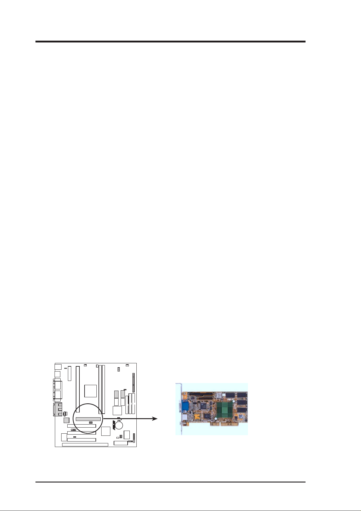
Accelerated Graphics Port
(available at the time of purchase as an option with Rage IIC only)
This motherboard provides an accelerated graphics port (AGP) slot to support a new
generation of graphics cards with ultra-high memory bandwidth, such as an ASUS
3D hardware accelerator . NOTE: You must set the VGAEN jumper to Disable when
using an external AGP card in order to disable the onboard AGP chipset.
R
P2Z-VM
P2Z-VM Accelerated Graphics Port (AGP)
26 ASUS P2Z-VM User’s Manual
III. HARDWARE SETUP
5. External Connectors
WARNING! Some pins are used for connectors or power sources. These are
clearly distinguished from jumpers in the Motherboard Layout. Placing jumper
caps over these connector pins will cause damage to your motherboard.
IMPORTANT: Ribbon cables should always be connected with the red stripe on the
Pin 1 side of the connector. The four corners of the connectors are labeled on the
motherboard. Pin 1 is the side closest to the power connector on hard drives and floppy
drives. IDE ribbon cable must be less than 46 cm (18 in.), with the second drive
connector no more than 15 cm (6 in.) from the first connector.
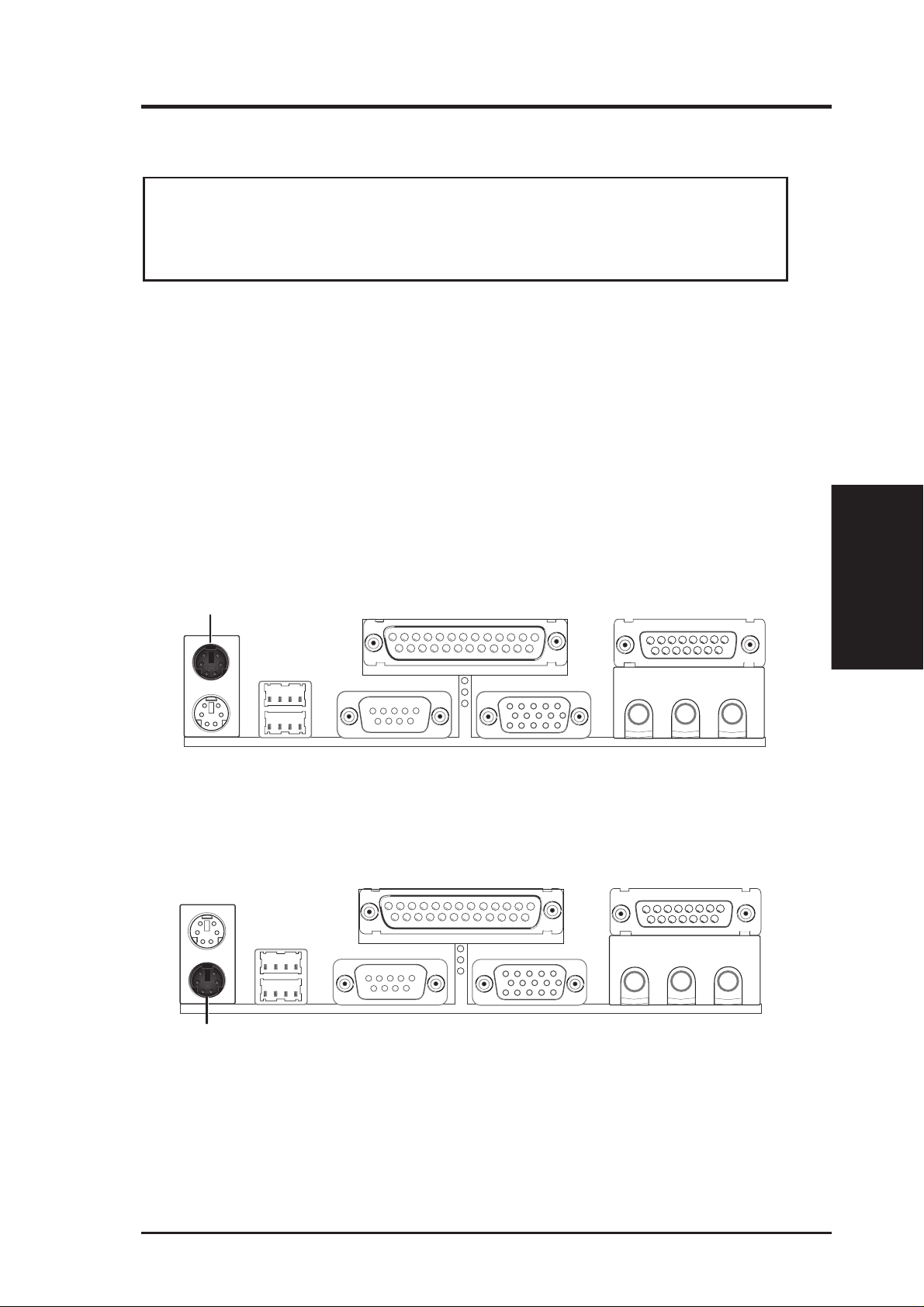
1. PS/2 Mouse Connector (6-pin PS2KBMS)
The system will direct IRQ12 to the PS/2 mouse if one is detected. If not detected, expansion cards can use IRQ12. See “PS/2 Mouse Control” in BIOS
Features Setup of BIOS SETUP.
PS/2 Mouse (6-pin Female)
2. PS/2 Keyboard Connector (6-pin PS2KBMS)
This connection is for a standard keyboard using a PS/2 plug (mini DIN). This
connector will not allow standard AT size (large DIN) keyboard plugs. You
may use a DIN to mini DIN adapter on standard AT keyboards.
PS/2 Keyboard (6-pin Female)
Connectors
III. H/W SETUP
ASUS P2Z-VM User’s Manual 27
III. H/W SETUP
Connectors
III. HARDWARE SETUP
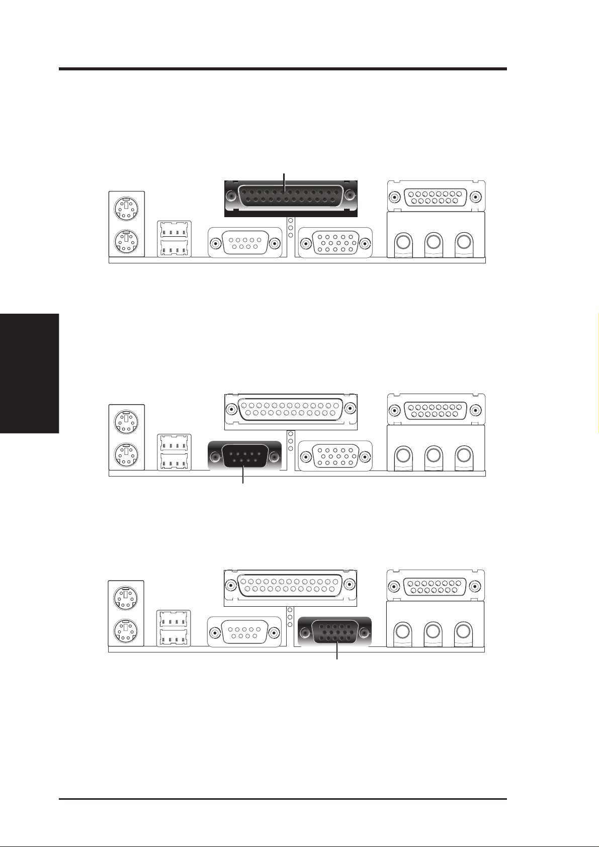
3. Parallel Port Connector (25-pin PRINTER)
You can enable the parallel port and choose the IRQ through “Onboard Parallel
Port” in Chipset Features Setup of BIOS SETUP.
NOTE: Serial printers must be connected to the serial port.
Parallel (Printer) Port (25-pin Female)
4. Serial Port COM1 Connector (9-pin COM1)
One serial port is ready for a mouse or other serial devices. A second serial port
is available using a serial port bracket connected from the motherboard to an
expansion slot opening. See “Onboard Serial Port” in Chipset Features Setup of
BIOS SETUP for settings.
Serial Port (9-pin Male) COM 1
5. Monitor (VGA) Output Connector (15-pin VGA)
This connector is for output to a VGA-compatible device.
VGA Monitor (15-pin Female)
28 ASUS P2Z-VM User’s Manual
III. HARDWARE SETUP
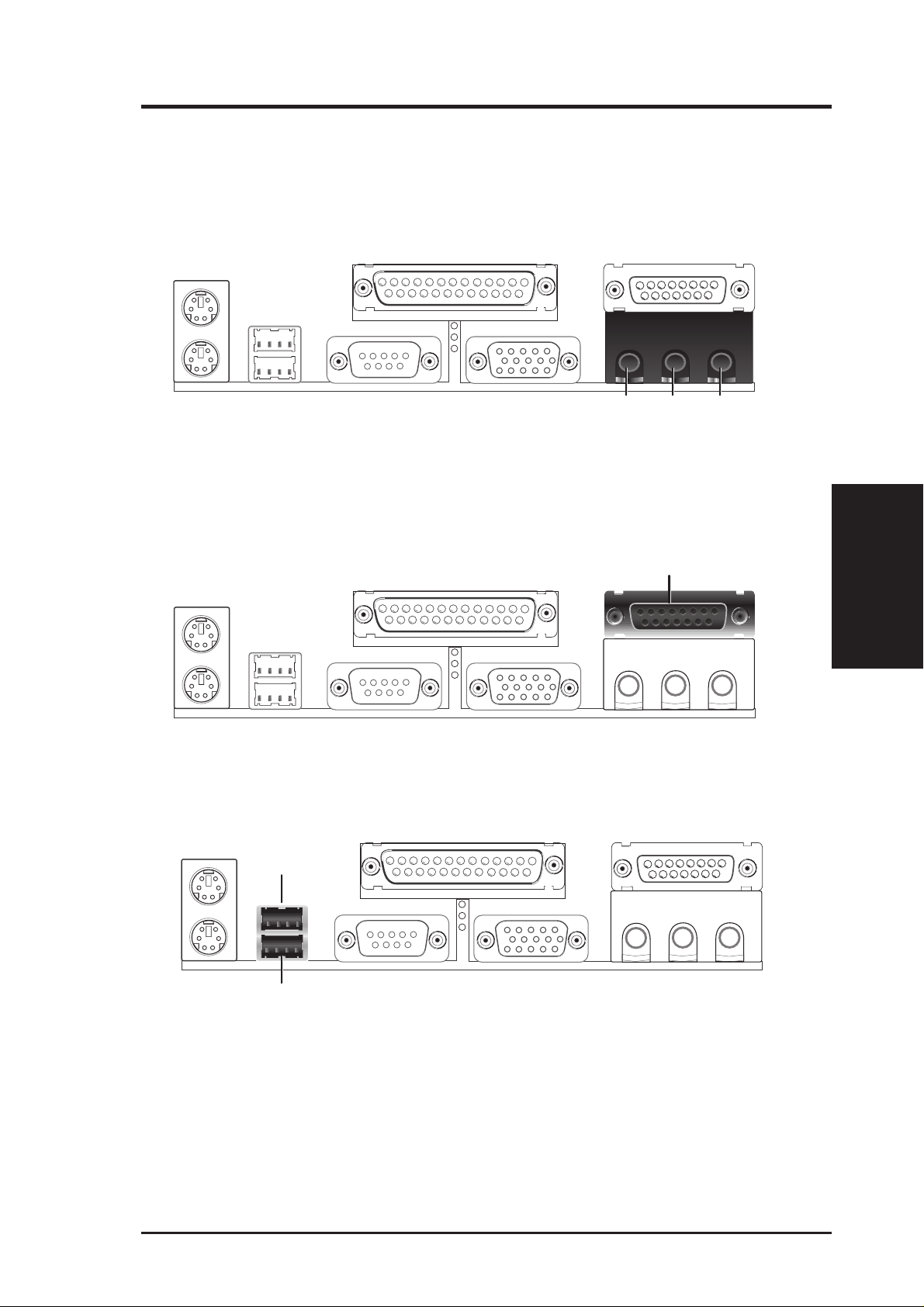
6. Audio Port Connectors (Three 1/8” Female) (with optional onboard audio)
Line Out can be connected to headphones or preferably powered speakers.
Line In allows tape players or other audio sources to be recorded by your com-
puter or played through the Line Out. Mic allows microphones to be connected
for inputing voice.
MicLine InLine Out
1/8" Stereo Audio Connectors
7. Joystick/MIDI Connector (15-pin GAME_AUDIO) (with optional onboard audio)
You may connect game joysticks or game pads to this connector for playing
games. Connect MIDI devices for playing or editing audio.
Joystick/Midi (15-pin Female)
8. Universal Serial BUS Ports 1 & 2 (Two 4-pin USB)
Two USB ports are available for connecting USB devices.
USB 1
Universal Serial Bus (USB) 2
Connectors
III. H/W SETUP
ASUS P2Z-VM User’s Manual 29
 Loading...