

Page 1
®
Pundit P2-AE2
Page 2

1
2
©2005
Pundit P2-AE2
V1 T2077
2005 5
2
Page 3
ASUSTeK COMPUTER INC.
15
886-2-2894-3447
0800-093-456
886-2-2890-7698
tw.asus.com
ASUS COMPUTER INTERNATIONAL
44370 Nobel Drive, Fremont ,CA 94538, USA
+1-510-608-4555
tmdl@asus.com
+1-502-933-8713
+1-502-995-0883
http://vip.asus.com/eservice/techserv.aspx
www.asus.com
ASUS COMPUTER GmbH
Harkort Str. 25, D-40880 Ratingen, Germany
49-2102-95990
49-2102-959911
www.asuscom.de
www.asuscom.de/sales
49-2102-95990 ... /
49-2102-959910 ...
49-2102-959911
www.asuscom.de/support
3
Page 4
........................................................................................
........................................................................................
..........................................................................................................
............................................................................................
........................................................................................
..........................................................................................
..........................................................
1.1
1.2
1.3
1.4
1.5
...............................................................................................
...........................................................
...........................................................
...................................................................................
...............................................................................
..........................................................
2.1
2.2
2.3
2.4 CPU
2.4.1 CPU
2.4.2
2.4.3 CPU
2.5
2.6
2.7
2.8
...................................................................................
...............................................................................
...................................................................................
...................................................................
....................................................................
..................................................................
................................................
.................................................................................
.....................................................................................
.................................................................................
.....................................................................
2
3
4
7
8
10
1-1
1-3
1-3
1-4
1-5
1-6
2-1
2-3
2-5
2-5
2-7
2-7
2-8
2-9
2-10
2-11
2-12
2-13
..........................................................
3.1
3.2
4
...............................................................................
.......................................................................................
3-1
3-3
3-3
Page 5
6
3.3
3.3.1
3.3.2 Drivers Menu
3.3.3 Utilities Menu
3.3.4
3.4 SoundMAX 4 XL
3.4.1
3.4.2 AudioESP
3.4.3
3.5 PC Probe II
3.5.1
3.6 Cool n QuietTM
.................................................................
..............................................................................
........................................................
....................................................
.......................................................
4.1
4.2
4.3
BIOS
5.1 BIOS
5.1.1 EZ Flash BIOS
5.1.2 CrashFree BIOS BIOS
5.1.3
5.2 BIOS
5.2.1 BIOS
5.2.2
5.2.3
5.2.4
...............................................................................
...................................................................
.......................................................................................
.................................................
........................................................
......................................................................
.....................................................................................
..........................................................
............................................................
................................................................
............................................................................
...................................................
.........................................
..............................
.............................
.................................................
............................................
................................................
..............................................
3-4
3-4
3-5
3-5
3-6
3-7
3-7
3-9
3-10
3-11
3-11
3-18
4-1
4-3
4-4
4-5
5-1
5-3
..........................
......................
5-3
5-5
5-6
5-9
5-10
5-10
5-10
5-11
5
Page 6
5.3 Main Menu
5.3.1 System Time [XX:XX:XX]
5.3.2 System Date [XX/XX/XXXX]
5.3.3 Primary IDE Master Slave
5.3.4 System Information
5.4 Advanced Menu
5.4.1 CPU Configuration
5.4.2 Chip Configuration
5.4.3 Onboard Devices Configuration
5.4.4 PCI PCI PnP
5.5 Power Menu
5.5.1 Suspend Mode [S1 (POS) & S3 (STR) Auto]
5.5.2 Repost Video on S3 Resume [No]
5.5.3 ACPI 2.0 Support [No]
5.5.4 ACPI APIC Support [Enabled]
5.5.5 APM Configuration
5.5.6 Hardware Monitor
5.6 Boot Menu
5.6.1 Boot Device Priority
5.6.2 Boot Settings Configuration
5.6.3 Security
5.7 Exit Menu
..............................................................
...............................................
..........................................
..............................................
....................................
..................................................
................................
.......................................
................................................
.....................................
......................................................
..........................................
...........................................................
..................................................
............................................................
........................
........
....................
....................
..............................
..........................
...............
5-12
5-12
5-12
5-12
5-14
5-15
5-15
5-18
5-21
5-22
5-23
5-23
5-23
5-23
5-23
5-24
5-27
5-28
5-28
5-29
5-31
5-34
Page 7
1) Pundit P2-AE2
•
CPU
•
IDE
•
SATA
•
2)
AC
•
•
•
SATA
•
3) Support CD
4) Recovery Pro CD
5)
6 )
•
DVD-ROM Combo DVD RW
7
Page 8
1.
2.
step-by-step
3.
4.
Jumper
5. BIOS
BIOS BIOS
Pundit P2-AE2
Pundit P2-AE2
8
Page 9
1.
2.
http://tw.asus.com
3
9
Page 10
•
•
•
•
•
•
•
•
10
•
•
•
•
•
IC
Page 11
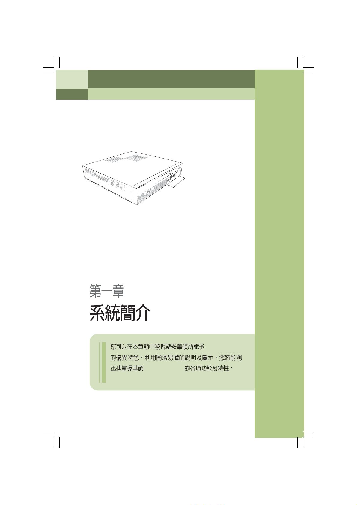
Pundit P2-AE2
System Introduction
Pundit P2-AE2
Page 12
1.1
1.2
1.3
1.4
1.5
...............................................................................................
...........................................................
...........................................................
...................................................................................
...............................................................................
1-3
1-3
1-4
1-5
1-6
Page 13
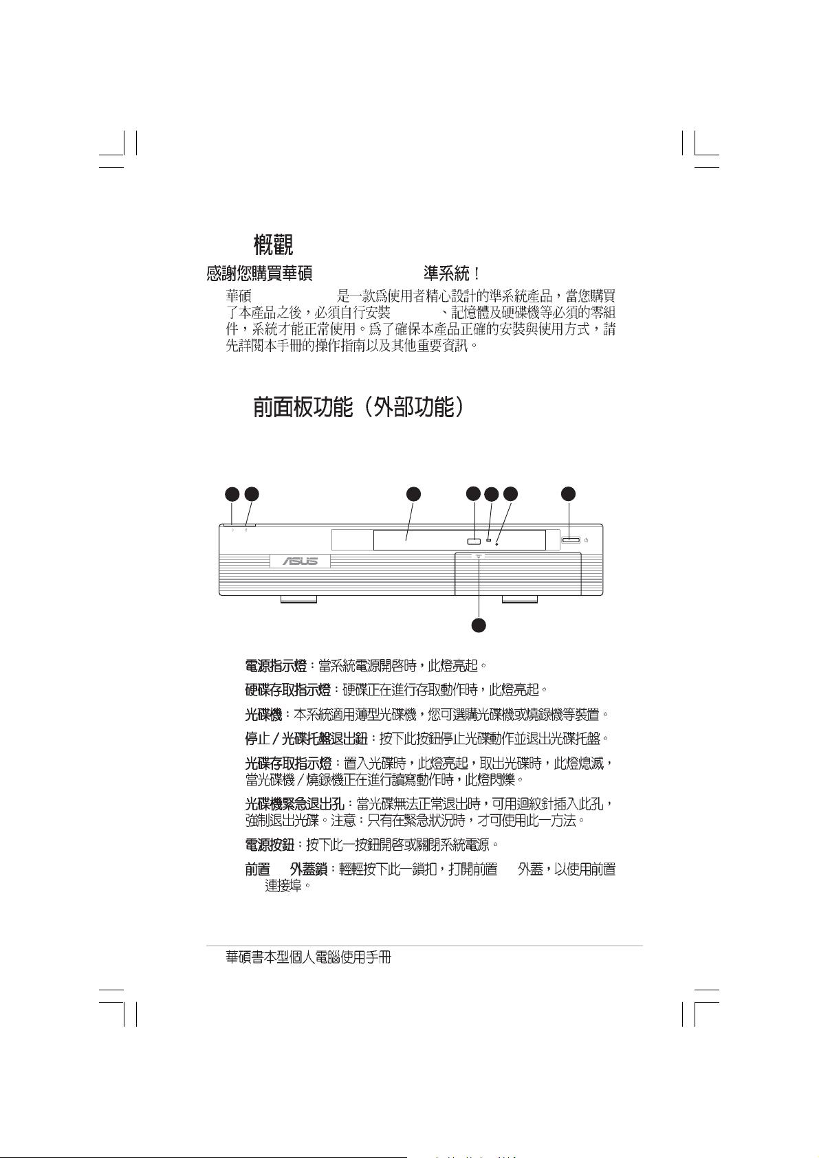
1.1
1.2
Pundit P2-AE2
Pundit P2-AE2
CPU
4
2
1
1.
2.
3.
4.
5.
6.
7.
8. I/O I/O
I/O
3
6
5
8
7
1-3
Page 14
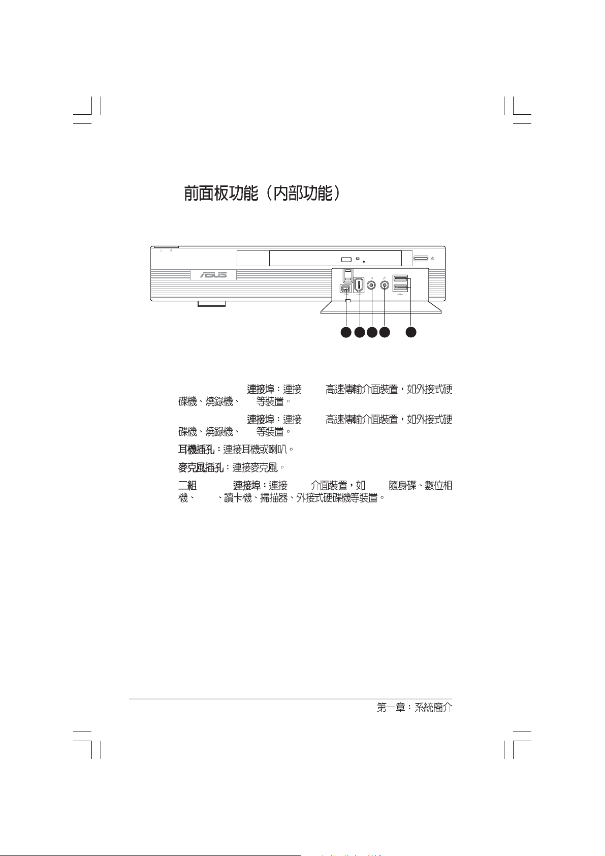
1.3
16
19 20 21 22 23
9. 4-pin IEEE 1394 1394
DV
10.6-pin IEEE 1394 1394
DV
11.
12.
13. USB 2.0 USB USB
PDA
119 10
1312
1-4
Page 15
1.4
1.
2.
3.
1 2 3
4 5
9
8
7
6
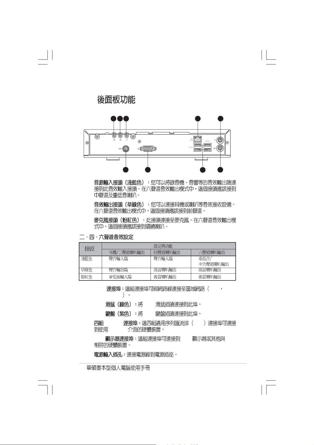
4. LAN LAN Local
Area Network
5. PS/2 PS/2
6. PS/2 PS/2
7. USB2.0 USB
USB 2.0
8. VGA VGA VGA
9.
1-5
Page 16
1.5
1
2
3
7
4
5
6
8
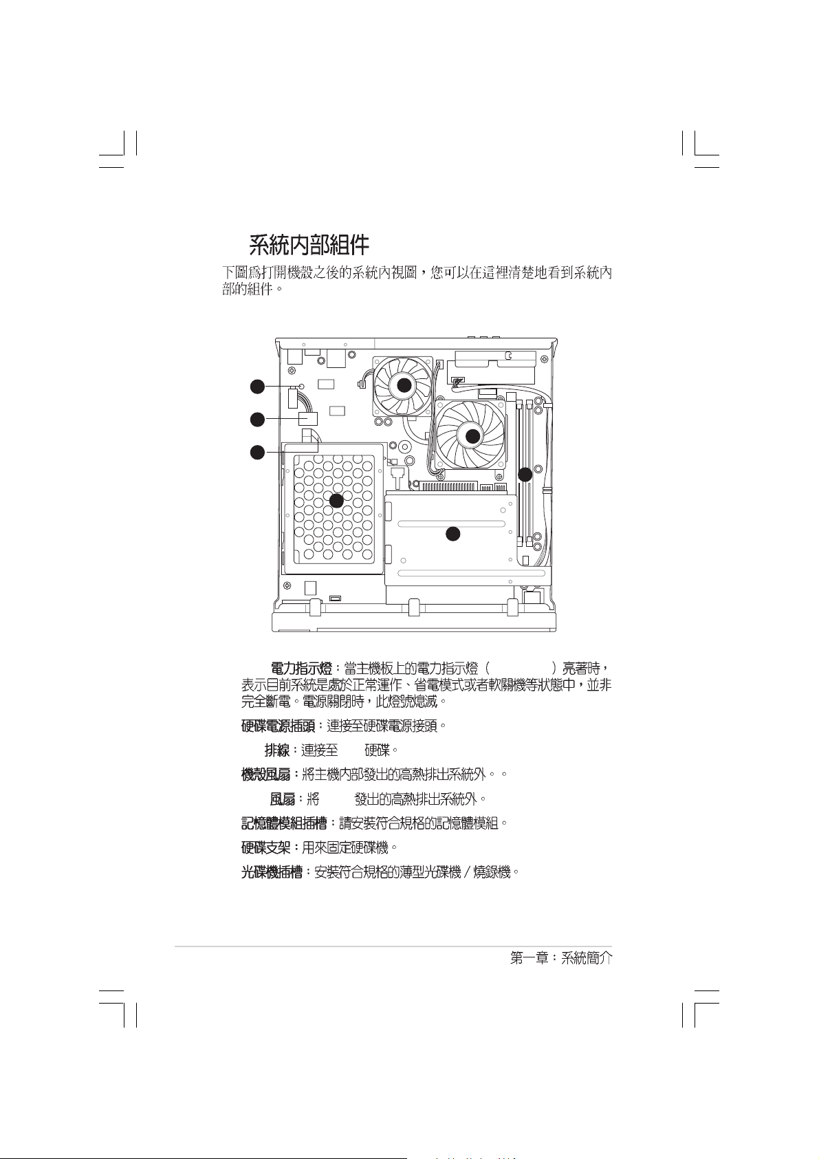
1. LED SB_PWR1
2.
3. IDE IDE
4.
5. CPU CPU
6.
7.
8.
1-6
Page 17
step-by-step
Starting up
Page 18
2.1
2.2
2.3
2.4 CPU
2.4.1
2.4.2
2.4.3
2.5
2.6
2.7
2.8
...................................................................................
...............................................................................
...................................................................................
CPU
CPU
.................................................................................
.....................................................................................
.................................................................................
2-3
2-4
2-5
...................................................................
..........................................................................
........................................................................
......................................................
.....................................................................
2-7
2-7
2-8
2-9
2-10
2-11
2-12
2-13
Page 19
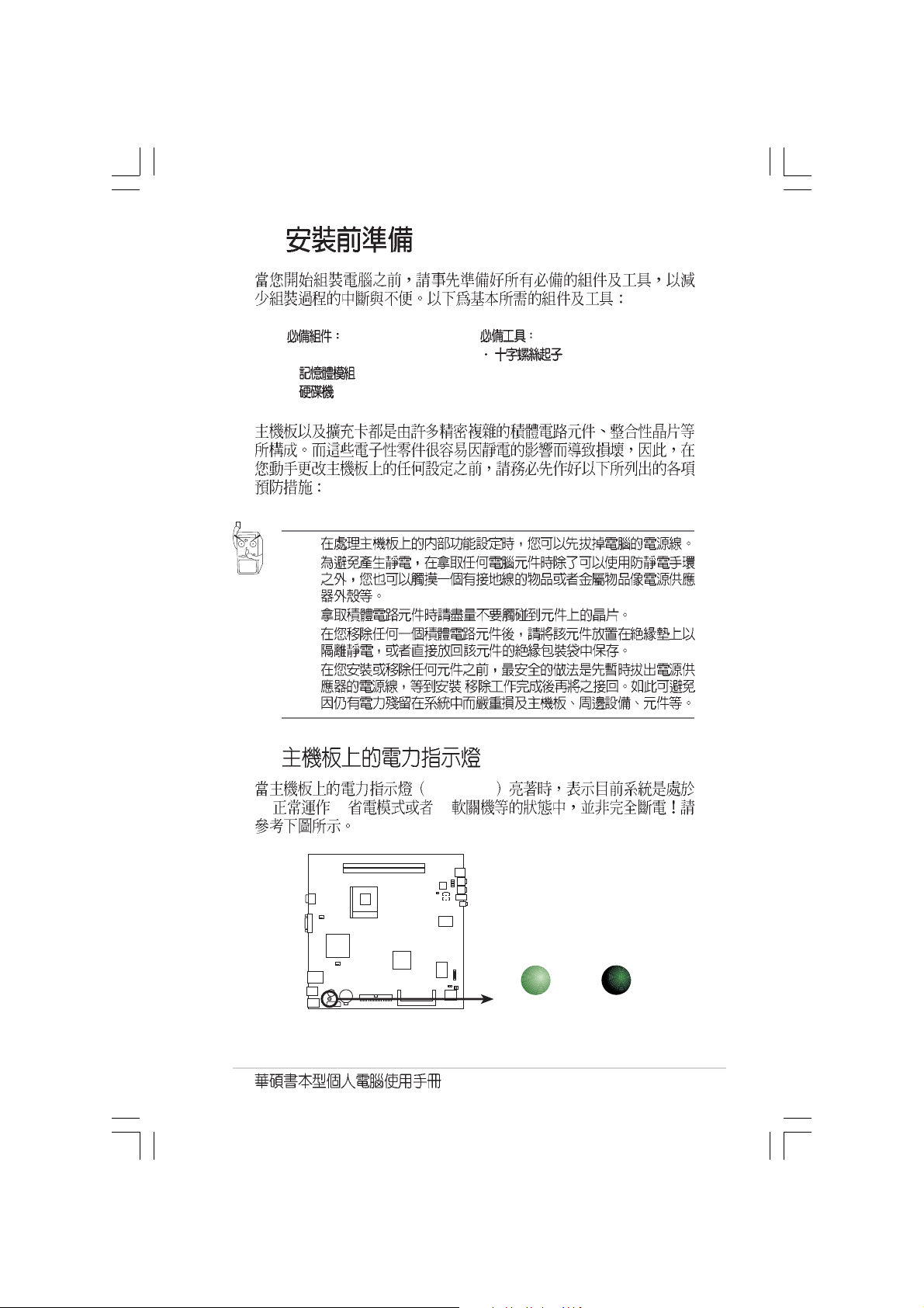
2.1
d
1. CPU
2.
3.
1.
2.
3.
4.
5.
SB_PWR
(1) (2) (3)
/
Onboard LED
ON
Standby
Power
SB_PWR1
OFF
Powere
Off
2-3
Page 20
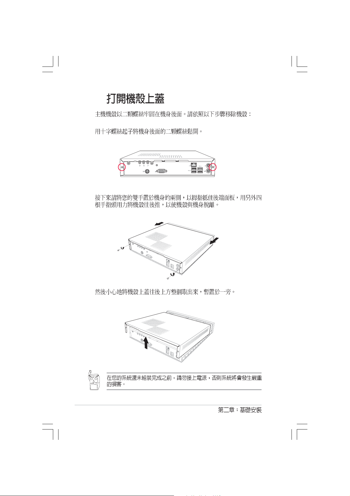
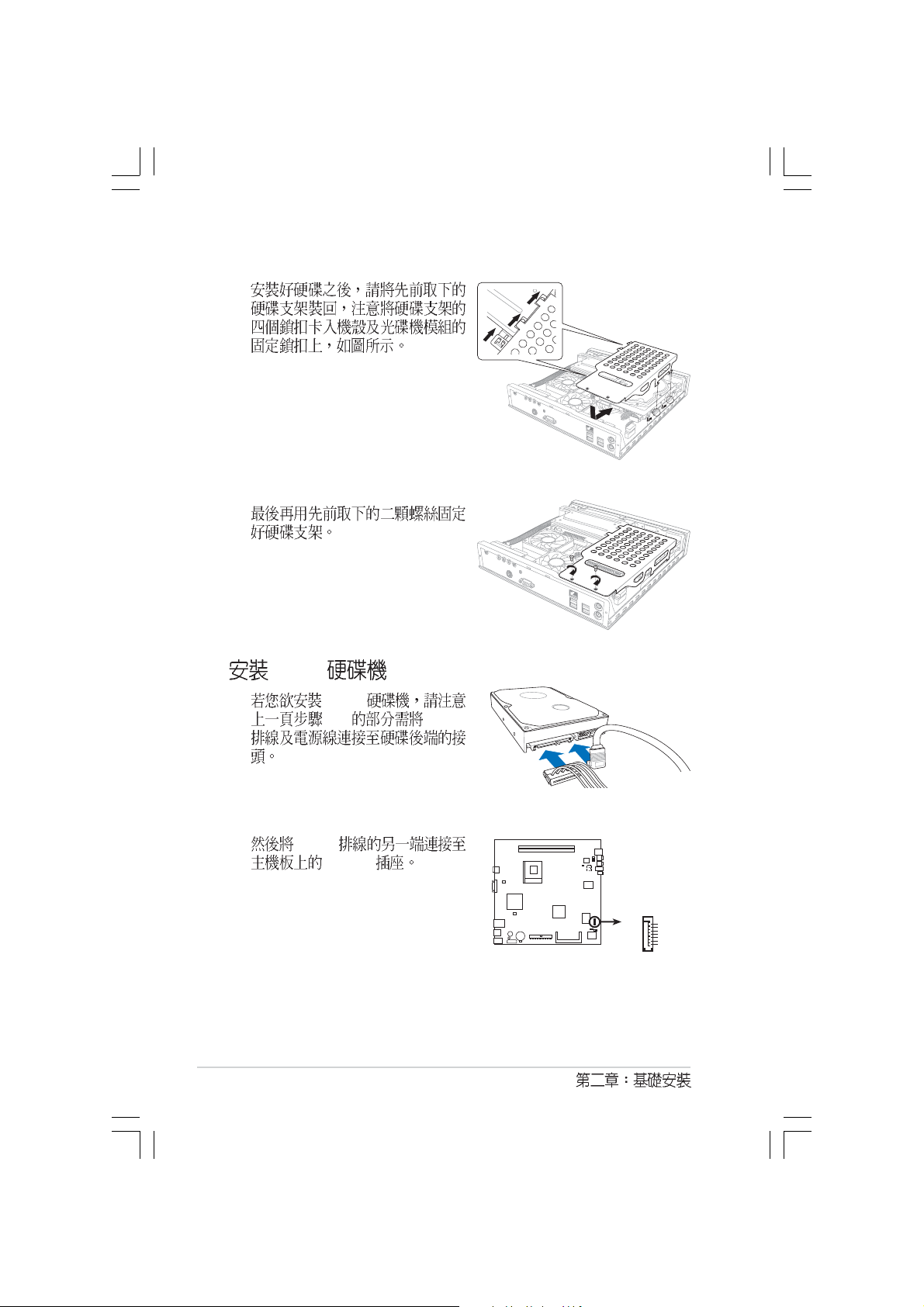
2.2
1.
2.
2-4
3.
Page 21
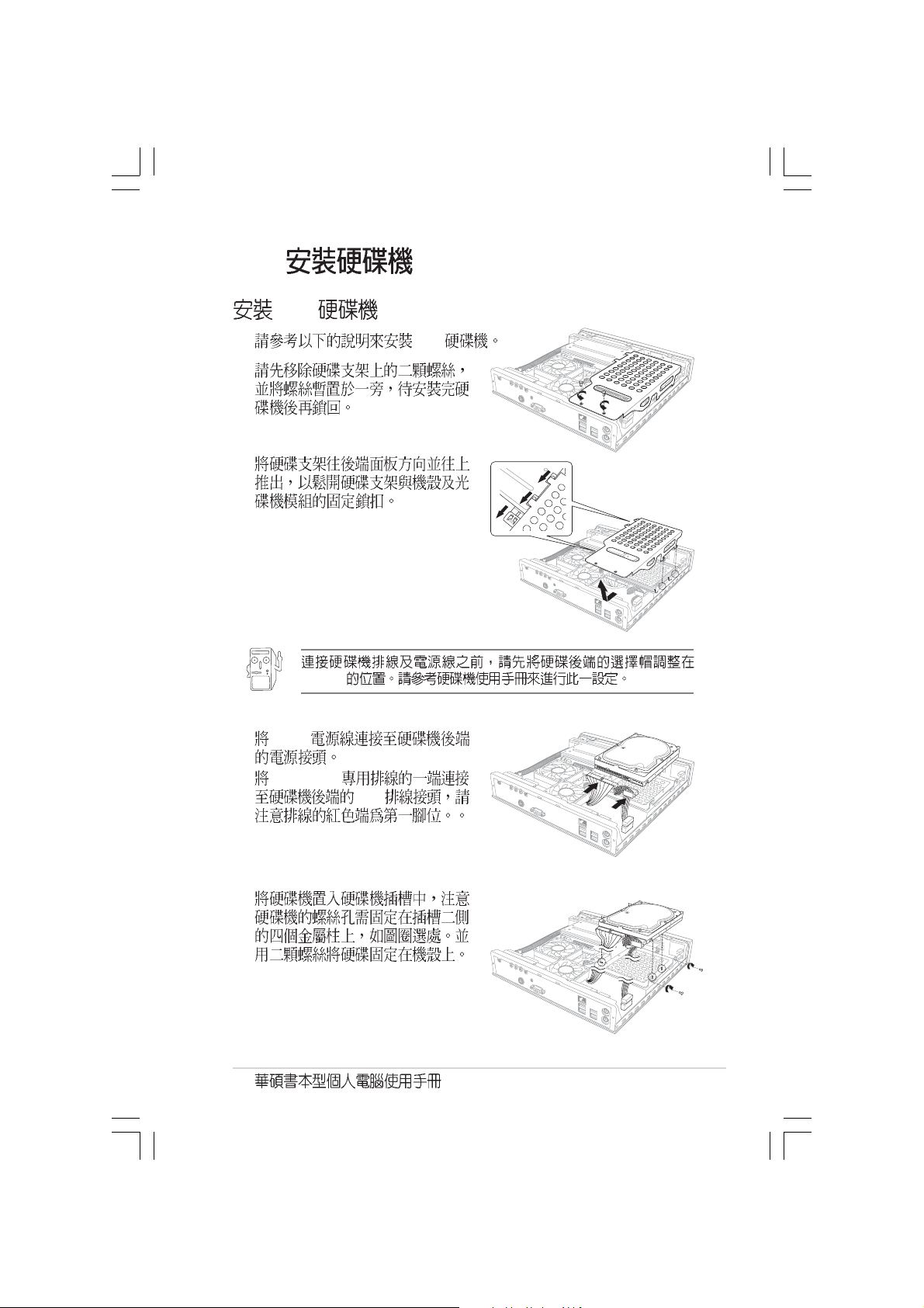
2.3
1.
2.
IDE
IDE
Master
3. 4-pin
4. 40-pin IDE
5.
IDE
2-5
Page 22
6.
1
7.
SATA
SATA
3-4 SATA
SATA
SATA1
SATA1
GND
RSATA_RXP1
RSATA_RXN
GND
RSATA_TXN1
RSATA_TXP1
SATA connector
GND
2-6
Page 23
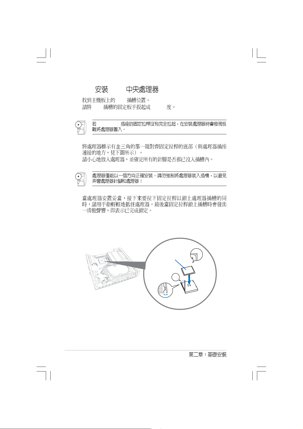
2.4 CPU
ZIF AMD AthlonTM 64 AthlonTM XP SempronTM
CPU 2600+ 3200+
2.4.1 CPU
CPU
CPU
1. CPU
2.
3. CPU
754
3
1
2
4.
5.
CHA_FAN
CPU
5
4
2-7
Page 24
2.4.2 CPU
1. CPU
2. CPU 90-100
Socket-754
3.
4.
5.
2-8
CPU
˚
Page 25
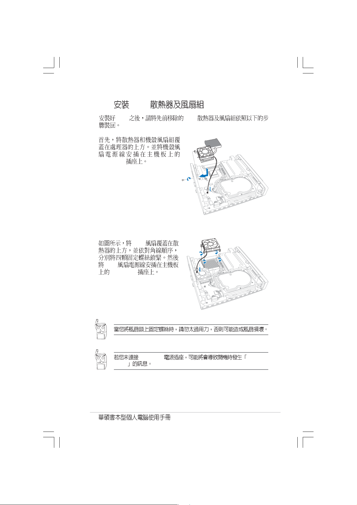
2.4.3 CPU
CPU CPU
1.
CHA_FAN
2. CPU
CPU
CPU_FAN
errors
CPU_FAN CPU FAN
2-9
Page 26
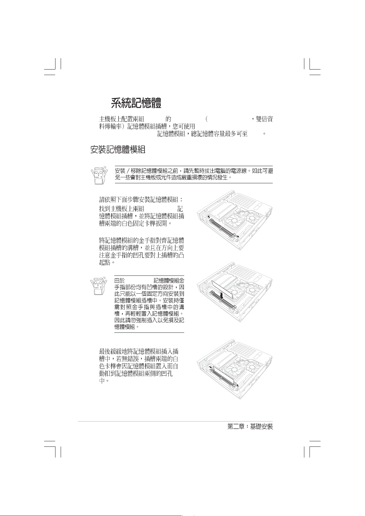
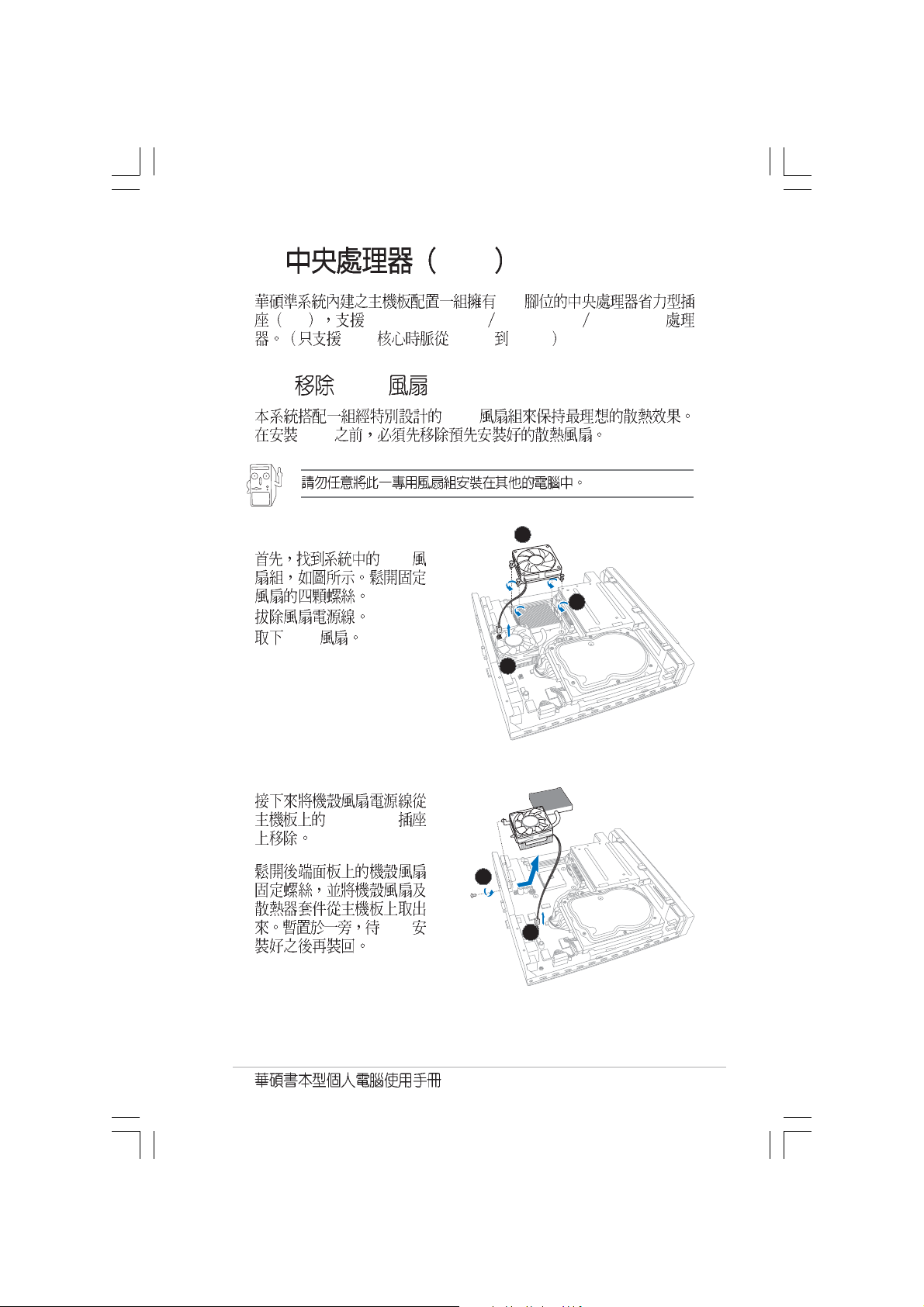
2.5
184-pin DDR DIMM Double Data Rate
unbuffered non-ECC 3200/2700/
2100/1600 DDR DIMM 2 GB
1. DDR DIMM
2.
DDR DIMM
2-10
3.
Page 27
2.6
1.
2.
2-11
Page 28
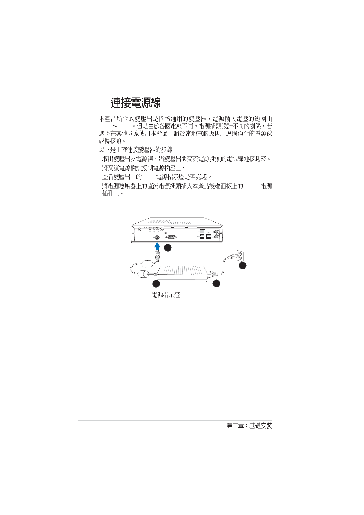
2.7
100V 240V
1.
2.
3. LED
4. DCIN
4
2
2-12
3
1
Page 29
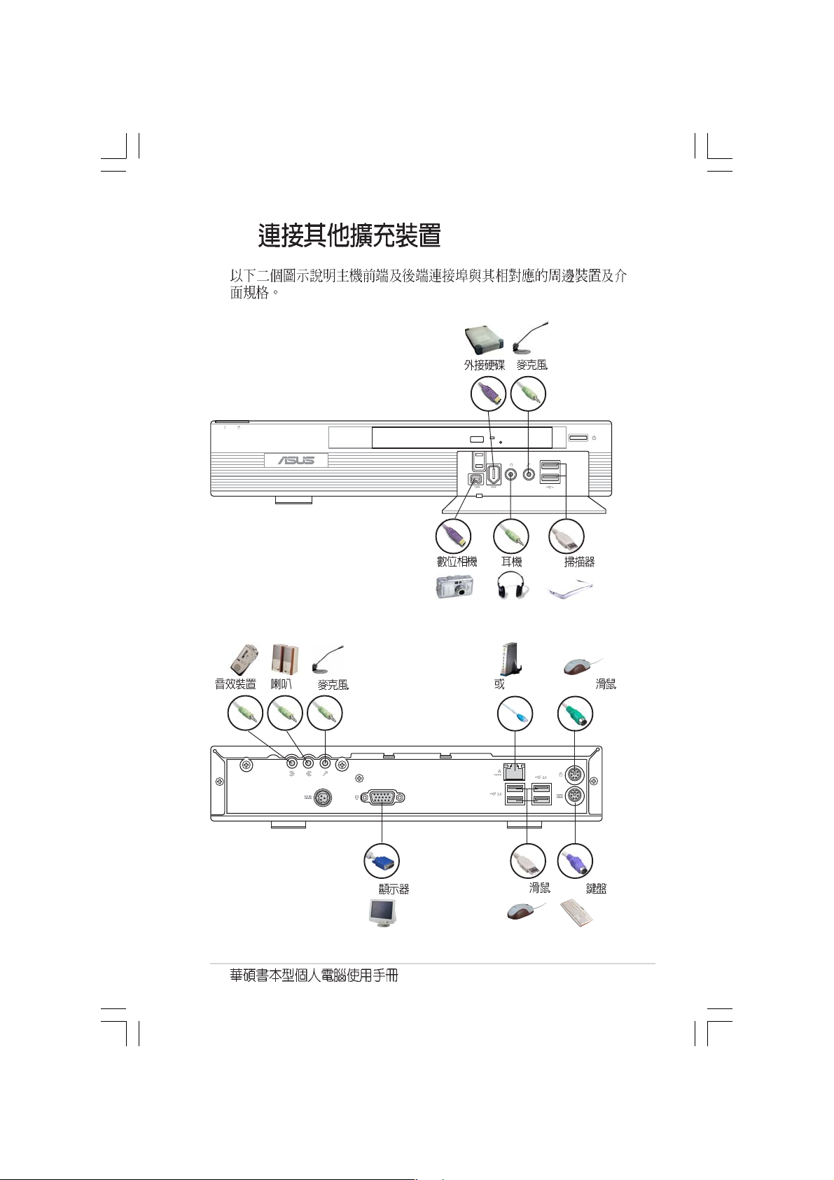
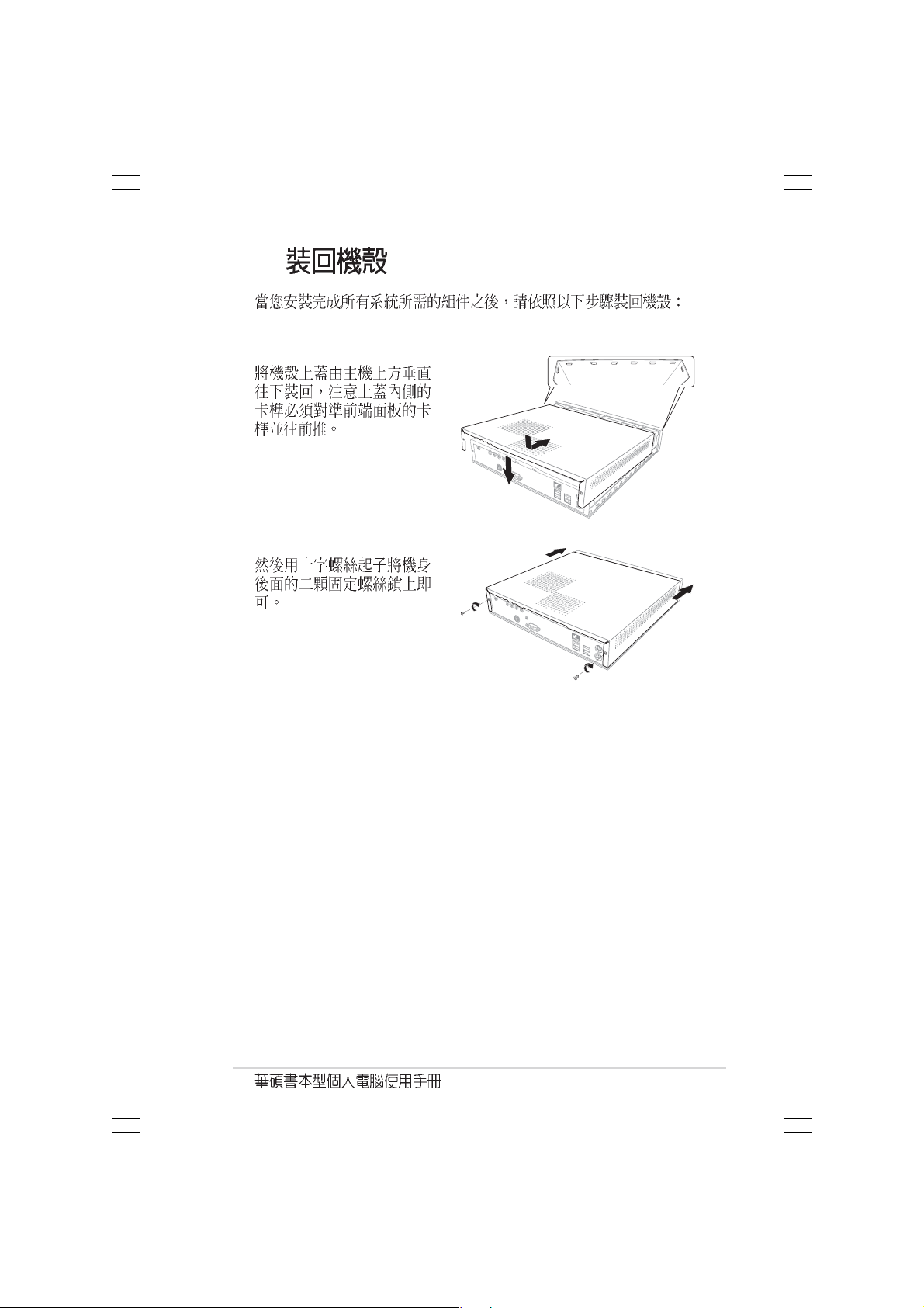
2.8
VGA
Hub Router
USB
PS/2
PS/2
2-13
Page 30

2-14
Page 31

Getting started
Page 32

3.1
3.2
3.3
3.3.1
3.3.2 Drivers Menu
3.3.3 Utilities Menu
3.3.4
3.4 SoundMAX 4 XL
3.4.1
3.4.2 AudioESP
3.4.3
3.5 PC Probe II
3.5.1
3.6 Cool n QuietTM
...............................................................................
.......................................................................................
.................................................................
..............................................................................
........................................................
...................................................
.........................................
..............................
.............................
.................................................
............................................
................................................
..............................................
....................................................
3-10
3-11
3-11
3-18
3-3
3-3
3-4
3-4
3-5
3-5
3-6
3-7
3-7
3-9
3-2
Page 33

3.1
Windows 2000/XP
Windows
Windows
3.2
Windows Windows
Windows
3-3
Page 34

3.3
3.3.1
Support CD
http://tw.asus.com.
3-4
BIN ASSETUP.EXE
Page 35

3.3.2 Drivers menu
VIA
VIA VIA Registry (INF)
VIA AGP VxD VIA ATAPI vendor support
VIA PCI IRQ Miniport
K8M800
K8M800
AD1888
AD1888 SoundMAX
VIA Rhine
VIA
USB 2.0
USB 2.0
Cool n Quiet
AMD Cool n Quiet
3.3.3 Utilities menu
3-5
Page 36

Microsoft DirectX9.0c
Microsoft DirectX 9.0c
ASUS PC Probe II
Adobe Acrobat Reader
Adobe Acrobat Reader PDF Portable Document
Format
Cool n Quiet
AMD Cool n Quiet
3.3.4
CPU
BIOS
TCP/IP
3-6
Page 37

3.4 SoundMAX 4 XL
AudioESP SoundMAX 4 XL
SoundMAX 4 XL
3.4.1
Windows XP
1.
SoundMax
SoundMax
2.
ADI AD1888 AC 97
SoundMax
3. SoundMAX
SoundMAX
3-7
Page 38

4.
MIDI
5. Audio Waizard
6. DLS
SoundMAX
MIDI
DLS DownLoadable Sound
3-8
Page 39

3.4.2 AudioESP
1.
2. AudioESP SPDIF
1.
AudioESP
2.
AudioESP
AudioESP
3.
3-9
Page 40

4.
3.4.3
/
/
3-10
Page 41

3.5 PC Probe II
CPU
3.5.1
ASUS PC
Probe II
Peripheral Component Interconnect
Windows Management Instrumentation
CPU
3-11
Page 42

PC PROBE II
Preferences
( ) ( )
3-12
Page 43

Scheme
CPU
Enable Monitoring Panel
OK
Config
3-13
Page 44

WMI
WMI (Windows Management Instrumentation)
Windows
WMI Information (+)
3-14
Page 45

DMI
PCI
DMI (Desktop Management Interface)
DMI Information (+)
PCI (Peripheral Component Interconnect)
PCI PCI Information (+)
3-15
Page 46

Usage
Usage CPU
Usage
CPU usage
CPU CPU CPU
Hyper-Threading*
3-16
* Intel CPU
Page 47

Hard Disk
Memory
3-17
Page 48

3.6 Cool n QuietTM
Cool n Quiet!
AMD Cool n Quiet! AMD Athlon XP
AMD Cool n QuietTM support CD
Cool n QuietTM CPU
CPU
Cool n Quiet!
Cool n Quiet!
1. <Del> BIOS
2. Advanced Cool n Quiet Enabled
5.4
3. Power ACPI 2.0 Support Yes
5.5
4. BIOS
5.
Windows 2000/XP
1. Windows 2000/XP
2.
3. ...
4.
5.
3-18
Page 49

3.3.3 Cool n QuietTM
Cool n QuietTM
Windows 2000
1.
2. > ASUS > Cool & Quiet > Cool & Quiet.
Windows XP
1.
2. > ASUS > Cool & Quiet > Cool & Quiet.
Cool n Quiet! CPU
(X) (
3-19
Page 50

3-20
Page 51

Jumper
Motherboard Information
Page 52

4.1
4.2
4.3
...............................................................................
...................................................................
.......................................................................................
4-3
4-4
4-5
Page 53

4.1
27.2cm (10.7in)
ADAPTER1
DDR DIMM2 (64/72-bit, 184-pin module)
DDR DIMM1 (64/72-bit, 184-pin module)
PWRSW1
AD1888
AUD_CON
CD
AUX
IE1394_1
USB12
FONT
MIC
FONT
LOUT
IE1394_2
LAN_USB34
USB_56
T:Mouse
B:Keyboard
VGA
PS/2
VGA
SB_PWR1
CPU_FAN1
BUZZER1
VIA
K8M800
CHA_FAN1
CR2032 3V
Lithium Cell
CMOS Power
IDE_PWR
Socket 754
PRI_IDE
VIA
VT8237R
PCI1
VIA
VT6307
Super
I/O
CLRTC
4Mb
BIOS
26.9cm (10.6in)
SATA1
LED_CON1
4-3
Page 54

4.2
l
t)
BIOS Clear RTC RAM CLRTC
CMOS
CMOS
1
2
3 CLRTC [1-2] CMOS
4 CLRTC [2-3]
5
6 <Del> BIOS
BIOS
CLRTC
2312
Clear CMOS
Norma
(Defaul
4-4
Clear RTC RAM
Page 55

4.3
1. IDE 40-1 pin PRI_IDE
IDE IDE
IDE CD-ROM ZIP MO
IDE
Master Slave
1. IDE
UltraDMA
2. UltraDMA133/100/66
PIN 1
IDE connector
PRI_IDE
NOTE: Orient the red markings
(usually zigzag) on the IDE
ribbon cable to PIN 1.
PIN1
UltraDMA133/100/66 IDE
80 IDE
80 IDE UltraDMA 133/100/66
4-5
Page 56

2. 3-pin
el
CPU_FAN1, CHA_FAN1
350mA 4.2 12
RPM Rotations Per
Minute
CPU
CPU jumpers
jumper
CPU_FAN1
GND
+12V
Rotation
Rotation
CHA_FAN1
Fan connectors
3. (4-pin AUX, CD)
CD CD-ROM AUX TV/FM
CD (Black)
AUX (White)
Internal audio connectors
4-6
Ground
Ground
Right Audio Chann
GND
+12V
Rotation
Left Audio Channel
Page 57

4. IDE (4-pin IDE_PWR)
R
T
IDE
IDE_PW
IDE power connector
+5V
GND
GND
5. (2-pin PWRSW)
PWRSW
Power switch connector
6. (10-1pin AUD_CON)
AUD_CON
SURR_R LOUT_L
SURR_L
GND
VREFOUT
+5V
+12V
LOUT_R
LINE_IN_LT
LINE_IN_R
Rear panel audio connector
4-7
Page 58

1
7. LED (6-pin LED_CON1)
LED
LED_CON1
1
Front pannel LED connector
8. SATA (7-pin SATA1)
Serial ATA Serial ATA
SATA connector
SATA Windows 2000 Service Pack4
Windows XP Service Pack1
SATA1
GND
RSATA_RXP1
RSATA_RXN
GND
RSATA_TXN1
RSATA_TXP1
GND
HDD LED
Power LED
4-8
Page 59

BIOS
BIOS
BIOS Information
BIOS
BIOS
Page 60

5.1 BIOS
5.1.1 EZ Flash BIOS
5.1.2 CrashFree BIOS BIOS
5.1.3
5.2 BIOS
5.2.1 BIOS
5.2.2
5.2.3
5.2.4
5.3 Main Menu
5.3.1 System Time [XX:XX:XX]
5.3.2 System Date [XX/XX/XXXX]
5.3.3 Primary IDE Master Slave
5.3.4 System Information
5.4 Advanced Menu
5.4.1 CPU Configuration
5.4.2 Chip Configuration
5.4.3 Onboard Devices Configuration
5.4.4 PCI PCI PnP
5.5 Power Menu
5.5.1 Suspend Mode [S1 (POS) & S3 (STR) Auto]
5.5.2 Repost Video on S3 Resume [No]
5.5.3 ACPI 2.0 Support [No]
5.5.4 ACPI APIC Support [Enabled]
5.5.5 APM Configuration
5.5.6 Hardware Monitor
5.6 Boot Menu
5.6.1 Boot Device Priority
5.6.2 Boot Settings Configuration
5.6.3 Security
5.7 Exit Menu
.....................................................................................
......................................................................
............................................................................
........................................................
..........................................................
............................................................
................................................................
..............................................................
...............................................
..........................................
..............................................
....................................
..................................................
................................
.......................................
................................................
.....................................
......................................................
..........................................
...........................................................
..................................................
............................................................
..........................
......................
........................
........
....................
....................
..............................
..........................
...............
5-3
5-3
5-5
5-6
5-9
5-10
5-10
5-10
5-11
5-12
5-12
5-12
5-12
5-14
5-15
5-15
5-18
5-21
5-22
5-23
5-23
5-23
5-23
5-23
5-24
5-27
5-28
5-28
5-29
5-31
5-34
5-2
BIOS
Page 61

5.1 BIOS
BIOS
1. ASUS EZ Flash Power-On Self
Test POST BIOS
2. ASUS CrashFree BIOS BIOS
BIOS
3. ASUS Update Windows BIOS
5.1.1 EZ Flash BIOS
EZ Flash BIOS
DOS EZ Flash BIOS
Power-On Self Test
POST <Alt> + <F2> EZ Flash
EZ Flash BIOS
1. http://tw.asus.com BIOS
K8S-MV-P.ROM
Support CD BIOS
2. BIOS CD
3. POST <Alt> + <F2>
EZ Flash
EZFlash starting BIOS update
Checking for floppy...
Floppy not found!
Checking for CD-ROM...
5-3
Page 62

4. BIOS EZ Flash
BIOS
EZFlash starting BIOS update
Checking for floppy...
Floppy not found!
Checking for CD-ROM...
CD-ROM found!
Reading file “K8VQ.rom”. Completed.
Start erasing.......|
Start programming...|
Flashed successfully. Rebooting.
BIOS
CD-ROM not found
BIOS
K8VQ.ROM not found!
K8VQ.ROM
5-4
BIOS
Page 63

5.1.2 CrashFree BIOS BIOS
CrashFree BIOS BIOS
BIOS
BIOS
BIOS
1.
2.
3.
BIOS
Bad BIOS checksum. Starting BIOS recovery...
Checking for floppy...
Floppy not found!
Checking for CD-ROM...
CD-ROM found!
4. BIOS
BIOS http://tw.asus.com
BIOS
BIOS
BIOS
BIOS
5-5
Page 64

5.1.3
BIOS
1. BIOS
2. BIOS
3. BIOS BIOS
4. BIOS
5. BIOS
1.
Windows
ISP
2. VX.XX.
XX
3.
BIOS
5-6
BIOS
Page 65

BIOS
BIOS
1. ASUS ASUSUpdate ASUSUpdate
2. Update
BIOS from the Internet
Next
3. FTP
Auto Select
Next
5-7
Page 66

4. BIOS
Next
5.
BIOS
BIOS
BIOS BIOS
BIOS BIOS
1. ASUS
ASUSUpdate ASUSUpdate
2. Update BIOS
from a file Next
3. BIOS
4.
BIOS
5-8
BIOS
Page 67

5.2 BIOS
BIOS Basic Input and Output System
BIOS
BIOS
BIOS
RUN SETUP BIOS
BIOS
EEPROM Electrical Erasable Programmable
Read-Only Memory BIOS EEPROM
BIOS BIOS
BIOS
CMOS RAM
BIOS
POST Power-On Self Test
DEL DEL
ALT - CTRL - DEL
BIOS
BIOS
BIOS
5-9
Page 68

5.2.1 BIOS
System Time [11:51:19]
System Date [Thu 05/07/2004]
Primary IDE Master : [ST320413A]
Primary IDE Slave : [ASUS CD-S520/A]
System Information
5.2.2
BIOS
Main
Advanced
Power
Boot
Exit BIOS
Use [ENTER], [TAB]
or [SHIFT-TAB] to
select a field.
Use [+] or [-] to
configure system time.
Select Screen
Select Item
+- Change Field
Tab Select Field
F1 General Help
F10 Save and Exit
ESC Exit
5-10
5.2.3
BIOS
Page 69

5.2.4
Advanced Power Boot Exit
Enter
[Enter]
Advanced Chipset settings
WARNING: Setting wrong values in the sections below
may cause system to malfunction.
Configure DRAM Timing by SPD [Enabled]
Memory Acceleration Mode [Auto]
DRAM Idle Timer [Auto]
DRAm Refresh Rate [Auto]
Graphic Adapter Priority [AGP/PCI]
Graphics Aperture Size [ 64 MB]
Spread Spectrum [Enabled]
ICH Delayed Transaction [Enabled]
MPS Revision [1.4]
Use [ENTER], [TAB]
or [SHIFT-TAB] to
select a field.
Use [+] or [-] to
configure system time.
Select Screen
Select Item
+- Change Field
Tab Select Field
F1 General Help
F10 Save and Exit
ESC Exit
Select Screen
Select Item
+- Change Option
F1 General Help
F10 Save and Exit
ESC Exit
PageUp/PageDown
5-11
Page 70

5.3 Main Menu
BIOS
System Time [11:51:19]
System Date [Thu 05/07/2004]
Primary IDE Master :[ST320413A]
Primary IDE Slave :[ASUS CD-S520/A]
System Information
Use [ENTER], [TAB]
or [SHIFT-TAB] to
select a field.
Use [+] or [-] to
configure system time.
Select Screen
Select Item
+- Change Field
Tab Select Field
F1 General Help
F10 Save and Exit
ESC Exit
5.3.1 System Time [XX:XX:XX]
5.3.2 System Date [XX/XX/XXXX]
5.3.3 Primary IDE Master Slave
BIOS IDE
IDE
Enter
5-12
Primary IDE Master
Device : Hard Disk
Vendor : ST320413A
Size : 20.0GB
LBA Mode : Supported
Block Mode : 16 Sectors
PIO Mode : 4
Async DMA : MultiWord DMA-2
Ultra DMA : Ultra DMA-5
SMART Monitoring: Supported
Type [Auto]
LBA/Large Mode [Auto]
Block(Multi-sector Transfer) [Auto]
PIO Mode [Auto]
DMA Mode [Auto]
SMART Monitoring [Auto]
32Bit Data Transfer [Disabled]
Acoustic [Maximum Performance]
Select the type
of device connected
to the system.
Select Screen
Select Item
+- Change Option
F1 General Help
F10 Save and Exit
ESC Exit
BIOS
Page 71

Device Vendor Size LBA Mode Block
Mode PIO Mode Async DMA Ultra DMA SMART monitoring
BIOS
N/A
Type [Auto]
IDE Auto
IDE CDROM IDE
ARMD ATAPI
IDE ZIP LS-120 MO
[Not Installed] [Auto] [CDROM] [ARMD]
LBA/Large Mode [Auto]
LBA [Auto]
LBA LBA
[Disabled] [Auto]
Block (Multi-sector Transfer) [Auto]
[Auto]
[Disabled]
[Disabled] [Auto]
PIO Mode [4]
PIO [Auto] [0] [1] [2] [3] [4]
DMA Mode [Auto]
DMA [Auto] [SWDMA0] [SWDMA1] [SWDMA2]
[MWDMA0] [MWDMA1] [MWDMA2] [UDMA0] [UDMA1] [UDMA2]
[UDMA3] [UDMA4] [UDMA5]
SMART Monitoring [Auto]
Smart Monitoring, Analysis,
and Reporting Technology [Auto] [Disabled] [Enabled]
32Bit Data Transfer [Disabled]
32 [Disabled] [Enabled]
Acoustics [Maximum Performance]
[Maximum Performance]
[Silent]
[Maximum Performance] [Medium] [Silent]
5-13
Page 72

5.3.4 System Information
BIOS
AMI BIOS
Version : 08.00.09
Revision : 01.15.0711
Build Date : 05/04/05
ID : A0242000
System Memory
Size : 256MB
LAN MAC EF9FE9F7F7F7
PCIdent Nr Chassis Serial Number
System Serial System Serial Number
Asset Tag Asset-1234567890
AMI BIOS
BIOS
System Memory
LAN MAC
MAC
PCIdent Nr
System Serial
Asset Tag
5-14
BIOS
Page 73

5.4 Advanced menu
Cool N’Quiet [Enabled]
CPU Configuration
Chipset
Onboard Devices Configuration
PCIPnP
Adjust system
frequency/voltage.
Cool N Quiet [Enabled]
AMD Cool N Quiet
[Enabled] [Disabled]
5.4.1 CPU Configuration
HyperTransport (HT) Configuration
Memory Configuration
Processor
Type : AMD Athlon (tm) 64 processor 2900+
Speed : 1800MHz
L1DC Size : 64KB
L1IC Size : 64KB
L2 Size : 128KB
CPUID : 10FC0
Patch ID : 41
HyperTransport
Configuration Options.
5-15
Page 74

Enter
HyperTransport Configuration
HyperTransport Configuration
HT Frequency [800 MHz]
HT DATA Width (Upstream) [16 BIT]
HT DATA Width (Downstream) [16 BIT]
HT Frequency [800 MHz]
HyperTransport K8 CPU AGP
[200 MHz] [400 Mhz] [600 Mhz] [800 Mhz]
HT DATA Width (Upstream) [16 BIT]
HyperTransport [16
BIT] [8 BIT]
HT DATA Width (Downstream) [16 BIT]
HyperTransport [16
BIT] [8 BIT]
Memory Configuration
Memory Configuration
Memory Configuration
Memory CLK :166 MHz
CAS Latency (Tcl) :2.5
RAS/CAS Delay (Trcd) :3 CLK
Min Active RAS (Tras) : 7 CLK
Row Precharge Time (Trp) : 3 CLK
RAS/RAS Delay (Trrd) :2 CLK
Row Cycle (Trc) :10 CLK
Row Refresh Cycle (Trfc) : 12 CLK
Read Write Delay (Trwt) :4 CLK
Read Preamble :7.5 ns
Asynchronous Latency :8 ns
Enable link
tristate during
the disconnected
state of an
LDTSTOP.
5-16
BIOS
Page 75

Memory Configuration
Memory Configuration
Memclock Mode [Auto]
MCT Timing Mode [Auto]
User Config Mode [Auto]
Bank Interleaving [Auto]
Burst Length [4 Beats]
Enable Clock to All DIMMs [Disabled]
SoftWare Memory Hole [Disabled]
Memclock Mode [Auto]
[Auto] [Limit] [Auto] [Limit]
Memclock Mode [Limit] Memcheck to CPU Ratio
Memcheck to CPU Ratio [Auto]
[1:1 (DDR 200)] [4:3
(DDR 266)] [3:2] [5:3 (DDR 333)] [2:1 (DDR 400)]
MCT Timing Mode [Auto]
[Auto] [Manual]
User Config Mode [Auto]
[Auto] [Manual]
Bank Interleaving [Auto]
[Auto] [Disabled]
Burst Lenght [4 Beats]
[8 Beats] [4 Beats] [2 Beats]
Enable Clock to All DIMMs [Disabled]
[Disabled] [Enabled]
SoftWare Memory Hole [Disabled]
[Disabled] [Enabled]
5-17
Page 76

5.4.2 Chip Configuration
AGP Bridge Configuration
SouthBridge Configuration
USB Configuration
AGP AGP Bridge Configuration
OnChip VGA Frame Buffer Size [64MB]
VLink 8X Supported [Enabled
AGP Mode [AGP 8X]
AGP Fast Write [Enabled]
Graphics Aperture Size [64MB]
AGP 3.0 Calibration Cycle [Disabled]
DBI Output for AGP Trans [Disabled]
OnChip VGA Frame Buffer Size [64MB]
[64MB] [32MB] [16MB] [8MB]
VLink 8X Supported [Enabled]
VIA 4X 8X
[Enabled] [Disabled]
5-18
BIOS
Page 77

AGP Mode [AGP 8X]
AGP 1.06GB [AGP 8X] [AGP
4X]
AGP Fast Write [Enabled]
AGP [Enabled] [Disabled]
Graphics Aperture Size [64MB]
AGP
[256MB] [128MB] [64MB] [32MB]
AGP 3.0 Calibration Cycle [Enabled]
AGP 3.0 Calibration Cycle [Enabled]
[Disabled]
DBI Output for AGP Trans [Disabled]
DBI AGP [Disabled] [Enabled]
SouthBridge Configuration
MPS Revision [1.4]
PCI Delay Transaction [Disabled]
[AGP 4X]
MPS Revision [1.4]
MPS [1.1] [1.4]
PCI Delay Transaction [Disabled]
PCI [Disabled]
[Enabled]
5-19
Page 78

USB USB Configuration
USB
Enter
USB Configuration
Module Version - 2.23.0-7.4
USB Devices Enabled :
None
USB 1.1 Ports Configuration [USB 8 Ports]
USB 2.0 Controller [Enabled]
Legacy USB Support [Auto]
USB 2.0 Controller Mode [HiSpeed]
USB Devices Enabled
USB None
USB 1.1 Ports Configuration [USB 8 Ports]
USB 1.1 [Disabled] [USB 2
Ports] [USB 4 Ports] [USB 6 Ports] [USB 8 Ports]
USB 2.0 Controller [Enabled]
USB 2.0 [Enabled] [Disabled]
Legacy USB Support [Auto]
USB [Auto]
USB Legacy
[Disabled] USB USB
[Auto] [Disabled] [Enabled]
USB 2.0 Controller Mode [HiSpeed]
USB 2.0 HiSpeed
480 Mbps FullSpeed 12 Mbps [HiSpeed]
[FullSpeed]
5-20
USB
BIOS
Page 79

5.4.3 Onboard Devices
Configuration
Onboard AC’97 Audio [Enabled]
OnChip SATA BOOTROM [Enabled]
Onboard LAN [Enabled]
Onboard LAN BOOT ROM [Enabled]
Onboard IEEE 1394 [Enabled]
Onboard AC 97 Audio [Enabled]
AC97
[Enabled] [Disabled]
OnChip SATA BOOTROM [Enabled]
SATA
[Enabled] [Disabled]
Onboard LAN [Enabled]
[Enabled] [Disabled]
[Enabled]
Onboard LAN BOOTROM [Enabled]
[Disabled] [Enabled]
Onboard IEEE 1394 [Enabled]
[Disabled] [Enabled]
IEEE 1394
5-21
Page 80

5.4.4 PCI PCI PnP
PCI/PnP PCI/PnP
IRQ DMA
Advanced PCI/PnP Settings
WARNING: Setting wrong values in below
sections may cause system to malfunction.
Plug And Play O/S [No]
PCI Latency Timer [64]
Allocate IRQ to PCI VGA [Yes]
Palette Snooping [Disabled]
IRQ-3 assigned to [PCI Device]
IRQ-4 assigned to [PCI Device]
IRQ-5 assigned to [PCI Device]
IRQ-7 assigned to [PCI Device]
IRQ-9 assigned to [PCI Device]
IRQ-10 assigned to [PCI Device]
IRQ-11 assigned to [PCI Device]
IRQ-14 assigned to [PCI Device]
IRQ-15 assigned to [PCI Device]
Plug and Play O/S [No]
[No] BIOS
PCI Latency Timer [64]
PCI [32] [64]
[96] [128] [160] [192] [224] [248]
Allocate IRQ to PCI VGA [Yes]
PCI IRQ
[Yes] [No]
Palette Snooping [Disabled]
MPEG
VGA [Disabled]
[Disabled] [Enabled]
NO: Lets the BIOS
configue all the devices
in the system.
YES: Lets the operating
system configure Plug
and Play (PnP) devices
not required for boot if
your system has a Plug
and Play operating
system.
[Yes] [No] [Yes]
[Enabled]
IRQ-xx assigned to [PCI Device]
IRQ PCI/PnP [PCI
Device] ISA [Reserved] [PCI
Device] [Reserved]
5-22
BIOS
Page 81

5.5 Power menu
APM
Suspend Mode [S1 (POS) & S3 (STR)]
Repost Video on S3 Resume [No]
ACPI 2.0 Support [No]
ACPI APIC Support [Enabled]
APM Configuration
Hardware Monitor
Select the ACPI state
used for System
Suspend.
5.5.1 Suspend Mode [S1 (POS) & S3 (STR) Auto]
[S1 (POS) Only] [S3 Only]
[S1 (POS) & S3 (STR) Auto]
5.5.2 Repost Video on S3 Resume [No]
Repost Vedio on S3 Resume
[Yes] [No]
5.5.3 ACPI 2.0 Support [No]
ACPI 2.0 [No] [Yes]
5.5.4 ACPI APIC Support [Enabled]
ACPI APIC RSDT
[Disabled] [Enabled]
5-23
Page 82

5.5.5 APM Configuration
Power Management/APM [Enabled]
Power Button Mode [On/Off]
Suspend Power Saving Type [C3]
Restore on AC Power Loss [Last State]
Power On By RTC Alarm [Disabled]
Power On External Modems [Disabled]
Power On PCI Device [Disabled]
Power on PS/2 Keyboard [Disabled]
Power on PS/2 Mouse [Disabled]
Power on OnBoard LAN [Disabled]
Power Management/APM [Enabled]
[Disabled]
Power Button Mode [On/Off]
On/Off suspend
[On/Off] [Standby] [Suspend]
Suspend Power Saving Type [C3]
Restore on AC Power Loss [Last State]
[Last State]
[Last State] [Power Off]
[Power On]
Select the ACPI state
used for System
Suspend.
[Enabled]
[C3] [S1]
[Power Off]
5-24
BIOS
Page 83

Power On By RTC Alarm [Disabled]
(RTC) [Enabled]
RTC Alarm Date RTC Alarm Hour RTC Alarm Minute
RTC Alarm Second
[Disabled] [Enabled]
RTC Alarm Date (Days)
<+> <->
[Everyday] [1] [2] [3]... ~ [31]
RTC Alarm Hour (Hours)
<+> <-> [00]
[1]... ~ [23]
RTC Alarm Minute (Minutes)
<+> <-> [00]
[1]... ~ [59]
RTC Alarm Second (Seconds)
<+> <-> [00]
[1]... ~ [59]
Power On External Modems [Disabled]
[Disabled]
[Disabled] [Enabled]
[Enabled]
5-25
Page 84

Power On PCI Device [Disabled]
[Enabled] PCI
ATX 1
5VSB [Disabled] [Enabled]
Power On PS/2 Keyboard [Disabled]
ATX
1 5VSB [Disabled] [Enabled]
Power On PS/2 Mouse [Disabled]
ATX
1 5VSB [Disabled] [Enabled]
Power On Onboard LAN [Disabled]
[Enabled]
[Disabled] [Enabled]
5-26
BIOS
Page 85

5.5.6 Hardware Monitor
Hardware Monitor
CPU Temperature [32.5ºC/90.5ºF]
MB Temperature [36.0ºC/96.5ºF]
Q-Fan Control [Enabled]
CPU Target Temperature [53ºC]
CPU Fan Speed [1798RPM]
Chassis Fan Speed [1534RPM]
VCORE Voltage [ 1.320V]
3.3V Voltage [ 3.345V]
5V Voltage [ 5.094V]
12V Voltage [11.880V]
CPU Temperature [xx.x /xx.x ]
MB Temperature [xx.x /xx.x ]
CPU
Q-Fan Control [Enabled]
ASUS Q-Fan
CPU [Disabled]
[Enabled]
CPU Target Temperature [xx ]
CPU
CPU Intel
®
Intel
FSC 5 3
CPU Fan Speed [xxxxRPM] or [N/A]
Chassis Fan Speed [xxxxRPM] or [N/A]
RPM Rotations Per Minute
VCORE Voltage, +3.3V Voltage, +5V Voltage, +12V Voltage
®
Fan Speed Control (FSC)
CPU
5-27
Page 86

5.6 Boot Menu
Boot Settings
Boot Device Priority
Boot Settings Configuration
Security
Specifies the Boot
Device Priority
sequence.
5.6.1 Boot Device Priority
Boot Device Priority
1st Boot Device [PM-ST330620A]
2nd Boot Device [PS-ASUS CD-S360]
3rd Boot Device [PXE 2.33]
1st~3rd Boot Device [PM-XXXXXXXXXX]
3rd
[xxxxx Drive] [Disabled]
1st 2nd
5-28
BIOS
Page 87

5.6.2 Boot Settings Configuration
Boot Settings Configuration
Quick Boot [Enabled]
Full Screen Logo [Disabled]
AddOn ROM Display Mode [Force BIOS]
Bootup Num-Lock [On]
PS/2 Mouse Support [Auto]
Wait For ‘F1’ If Error [Enabled]
Hit ‘DEL’ Message Display [Enabled]
Interrupt 19 Capture [Disabled]
Allows BIOS to skip
certain tests while
booting. This will
decrease the time
needed to boot the
system.
Quick Boot [Enabled]
[Disabled] BIOS
[Disabled] [Enabled]
Full Screen Logo [Disabled]
[Enable]
[Disabled] [Enabled]
MyLogoTM Full Screen Logo
[Enabled]
Add On ROM Display Mode [Force BIOS]
BIOS] [Keep Current]
Bootup Num-Lock [On]
NumLock [Off]
[On]
POST
[Force
PS/2 Mouse Support [Auto]
PS/2 [Disabled]
[enabled] [Auto]
Wait for F1 If Error [Enabled]
[Enabled]
[F1]
[Disabled] [Enabled]
5-29
Page 88

Hit DEL Message Display [Enabled]
[Enabled] Press DEL
to run Setup [Disabled] [Enabled]
Interrupt 19 Capture [Disabled]
PCI SCSI
Interrupt 19 [Enabled]
[Disabled] [Enabled]
5-30
BIOS
Page 89

5.6.3 Security
Security Settings
Supervisor Password : Not Installed
User Password : Not Installed
Change Supervisor Password
<Enter> to change
password.
<Enter> again to
disable password.
Change Supervisor Password
Not Installed
Installed
Supervisor Password
1. Change Supervisor Password Enter
2. Enter Password
Enter
3. Enter Confirm Password
Password Installed.
Password do not match!
Supervisor Password
Installed
Change Supervisor Password Enter
Password Enter Password
uninstalled.
BIOS CMOS RTC
4.3
5-31
Page 90

Security Settings
Supervisor Password : Installed
User Password : Not Installed
Change Supervisor Password
User Access Level [Full Access]
Change User Password
Clear User Password
Password Check [Setup]
User Access Level [Full Access]
BIOS
BIOS [No Access] [View Only]
[Limited] [Full Access]
No Access BIOS
View Only BIOS
Limited BIOS
Full Access BIOS
Change User Password
Not Installed
Installed
<Enter> to change
password.
<Enter> again to
disabled password.
User Password
1. Change User Password Enter
2. Enter Password
Enter
3. Confirm Password
Password Installed.
Password do not match!
Installed
5-32
User Password
BIOS
Page 91

Change User Word Enter Password
Enter Password uninstalled.
Clear User Password
Password Check [Setup]
[Setup] BIOS BIOS
[Always] BIOS
[Setup] [Always]
5-33
Page 92

5.7 Exit Menu
Exit BIOS
BIOS
Exit Options
Exit & Save Changes
Exit & Discard Changes
Discard Changes
Load Setup Defaults
Esc BIOS
F10 BIOS
Exit & Save Changes
BIOS
CMOS Enter
[OK] CMOS BIOS
[Cancel] BIOS
Exit system setup
after saving the
changes.
F10 key can be used
for this operation.
5-34
BIOS Esc BIOS
Discard configuration
changes and exit now? [OK] BIOS
[Cancel] BIOS
BIOS
Page 93

Exit & Discard Changes
Enter [OK]
CMOS BIOS
[Cancel] BIOS
Discard Changes
Enter [OK]
BIOS
Load Setup Defaults
F5 Enter
[OK] BIOS
[Cancel] BIOS
BIOS
BIOS
BIOS [Cancel]
5-35
Page 94

5-36
BIOS
 Loading...