

Page 1
Pundit P1-AH2
ASUS PC (Desktop Barebone)
Page 2
ii
Copyright © 2006 ASUSTeK COMPUTER INC. All Rights Reserved.
No part of this manual, including the products and software described in it, may be reproduced,
transmitted, transcribed, stored in a retrieval system, or translated into any language in any form
or by any means, except documentation kept by the purchaser for backup purposes, without the
express written permission of ASUSTeK COMPUTER INC. (“ASUS”).
Product warranty or service will not be extended if: (1) the product is repaired, modified or
altered, unless such repair, modification of alteration is authorized in writing by ASUS; or (2) the
serial number of the product is defaced or missing.
ASUS PROVIDES THIS MANUAL “AS IS” WITHOUT WARRANTY OF ANY KIND, EITHER EXPRESS
OR IMPLIED, INCLUDING BUT NOT LIMITED TO THE IMPLIED WARRANTIES OR CONDITIONS OF
MERCHANTABILITY OR FITNESS FOR A PARTICULAR PURPOSE. IN NO EVENT SHALL ASUS,
ITS DIRECTORS, OFFICERS, EMPLOYEES OR AGENTS BE LIABLE FOR ANY INDIRECT, SPECIAL,
INCIDENTAL, OR CONSEQUENTIAL DAMAGES (INCLUDING DAMAGES FOR LOSS OF PROFITS, LOSS
OF BUSINESS, LOSS OF USE OR DATA, INTERRUPTION OF BUSINESS AND THE LIKE), EVEN IF ASUS
HAS BEEN ADVISED OF THE POSSIBILITY OF SUCH DAMAGES ARISING FROM ANY DEFECT OR
ERROR IN THIS MANUAL OR PRODUCT.
SPECIFICATIONS AND INFORMATION CONTAINED IN THIS MANUAL ARE FURNISHED FOR
INFORMATIONAL USE ONLY, AND ARE SUBJECT TO CHANGE AT ANY TIME WITHOUT NOTICE, AND
SHOULD NOT BE CONSTRUED AS A COMMITMENT BY ASUS. ASUS ASSUMES NO RESPONSIBILITY
OR LIABILITY FOR ANY ERRORS OR INACCURACIES THAT MAY APPEAR IN THIS MANUAL,
INCLUDING THE PRODUCTS AND SOFTWARE DESCRIBED IN IT.
Products and corporate names appearing in this manual may or may not be registered
trademarks or copyrights of their respective companies, and are used only for identification or
explanation and to the ownersʼ benefit, without intent to infringe.
E257 4
Firs t E diti o n V1
June 2 0 06
Page 3
iii
Table of contents
Notices ................................................................................................ vi
Safety information ............................................................................. vii
About this guide .................................................................................viii
System package contents .................................................................... x
Cha p te r 1 : S y ste m I n tro d uc t ion
1.1 Welcome! .............................................................................. 1-2
1.2 Front panel .......................................................................... 1-2
1.3 Rear panel ............................................................................. 1-4
1.4 Internal components ............................................................. 1-6
Cha p te r 2 : Bas i c I nst a ll a tio n
2.1 Preparation ........................................................................... 2-2
2.2 Before you proceed .............................................................. 2-2
2.3 Removing the side cover ...................................................... 2-3
2.4 Removing the front panel cover ........................................... 2-4
2.5 Removing the storage drive assembly .................................. 2-4
2.6 Removing the CPU fan and heatsink ..................................... 2-5
2.7 Central Processing Unit (CPU) .............................................. 2-6
2.7.1 Overview ................................................................. 2-6
2.7.2 Installing CPU .......................................................... 2-6
2.7.3 Installing the heatsink and fan ................................ 2-8
2.8 Installing a DIMM ................................................................... 2-8
2.8.1 Memory configurations ........................................... 2-8
2.8.2 Installing a DDR2 DIMM ......................................... 2-11
2.8.3 Removing a DDR2 DIMM ........................................ 2-11
2.9 Expansion slots ................................................................... 2-12
2.9.1 PCI slots ................................................................ 2-12
2.9.2 Installing an expansion card .................................. 2-12
2.10 Installing an optical drive .................................................... 2-14
2.11 Reinstalling the storage drive assembly .............................2-15
2.12 Installing the foot stand .....................................................2-16
2.13 Reinstalling the front panel cover and the cover ................ 2-16
Page 4
iv
Table of contents
Cha p te r 3 : Sta r ti n g u p
3.1 Installing an operating system .............................................. 3-2
3.2 Powering up .......................................................................... 3-2
3.3 Support CD information ........................................................ 3-2
3.3.1 Running the support CD .......................................... 3-3
3.3.2 Utilities menu .......................................................... 3-4
3.3.3 ASUS contact information ...................................... 3-5
3.4 Software information ............................................................ 3-5
3.4.1 ASUS PC Probe II ..................................................... 3-5
3.4.2 DTS function ......................................................... 3-12
Cha p te r 4 : Mot h er b oar d I n fo
4.1 Introduction .......................................................................... 4-2
4.2 Motherboard layout .............................................................. 4-2
4.3 Jumpers ................................................................................ 4-3
4.4 Connectors ........................................................................... 4-5
Cha p te r 5 : BIO S I n for m at i on
5.1 Managing and updating your BIOS ........................................ 5-2
5.1.1 ASUS Update utility ................................................ 5-2
5.1.2 Creating a bootable floppy disk .............................. 5-5
5.1.3 ASUS EZ Flash utility .............................................. 5-5
5.1.4 AwardBIOS Flash utility ........................................... 5-7
5.1.5 Saving the current BIOS file .................................... 5-9
5.1.6 ASUS CrashFree BIOS utility .................................. 5-10
5.2 BIOS setup program ............................................................ 5-11
5.2.1 BIOS menu screen ................................................. 5-12
5.2.2 Menu bar ............................................................... 5-12
5.2.3 Navigation keys ..................................................... 5-13
5.2.4 Menu items ........................................................... 5-13
5.2.5 Sub-menu items .................................................... 5-13
5.2.6 Configuration fields ............................................... 5-13
5.2.7 Pop-up window ...................................................... 5-14
5.2.8 General help .......................................................... 5-14
Page 5

v
Table of contents
5.3 Main menu ........................................................................... 5-15
5.3.1 System Time ........................................................ 5-15
5.3.2 System Date ........................................................ 5-15
5.3.3 Primary IDE Master/Slave ...................................... 5-16
5.3.4 First/Second SATA Master ...................................5-18
5.3.5 HDD SMART Monitoring ......................................... 5-19
5.3.6 Installed Memory ................................................... 5-19
5.3.7 Usable Memory ...................................................... 5-19
5.4 Advanced menu .................................................................. 5-20
5.4.1 CPU Configuration ................................................. 5-17
5.4.2 Chipset .................................................................. 5-21
5.4.3 PCIPnP ................................................................... 5-22
5.4.4 Onboard Devices Configuration ............................. 5-23
5.5 Power menu ........................................................................ 5-26
5.5.1 ACPI Suspend Type .............................................. 5-26
5.5.2 ACPI APIC Support ................................................ 5-26
5.5.3 APM Configuration ................................................5-27
5.5.4 Hardware Monitor .................................................. 5-29
5.6 Boot menu .......................................................................... 5-31
5.6.1 Boot Device Priority .............................................. 5-31
5.6.2 Hard Disk Drive ..................................................... 5-31
5.6.3 Boot Settings Configuration ................................. 5-32
5.6.4 Security ................................................................. 5-33
5.7 Exit menu ............................................................................ 5-34
Page 6
vi
Notices
Fed er al Co mm un ica ti on s C om mi ssi on S tat em en t
This device complies with Part 15 of the FCC Rules. Operation is subject to
the following two conditions:
•
This device may not cause harmful interference, and
•
This device must accept any interference received including
interference that may cause undesired operation.
This equipment has been tested and found to comply with the limits for a
Class B digital device, pursuant to Part 15 of the FCC Rules. These limits
are designed to provide reasonable protection against harmful interference
in a residential installation. This equipment generates, uses and can radiate
radio frequency energy and, if not installed and used in accordance with
manufacturerʼs instructions, may cause harmful interference to radio
communications. However, there is no guarantee that interference will
not occur in a particular installation. If this equipment does cause harmful
interference to radio or television reception, which can be determined by
turning the equipment off and on, the user is encouraged to try to correct
the interference by one or more of the following measures:
•
Reorient or relocate the receiving antenna.
•
Increase the separation between the equipment and receiver.
•
Connect the equipment to an outlet on a circuit different from that to
which the receiver is connected.
•
Consult the dealer or an experienced radio/TV technician for help.
Can ad ia n D ep ar tme nt o f C om mu nic at io ns St at eme nt
This digital apparatus does not exceed the Class B limits for radio noise
emissions from digital apparatus set out in the Radio Interference
Regulations of the Canadian Department of Communications.
This class B digital apparatus complies with Canadian ICES-003.
WARNING! The use of shielded cables for connection of the monitor to
the graphics card is required to assure compliance with FCC regulations.
Changes or modifications to this unit not expressly approved by the
party responsible for compliance could void the userʼs authority to
operate this equipment.
Page 7
vii
Safety information
Ele ct ri cal s af ety
•
To prevent electrical shock hazard, disconnect the power cable from
the electrical outlet before relocating the system.
•
When adding or removing devices to or from the system, ensure that
the power cables for the devices are unplugged before the signal cables
are connected.
•
If the power supply is broken, do not try to fix it by yourself. Contact a
qualified service technician or your retailer.
Ope ra ti on sa fe ty
•
Before installing devices into the system, carefully read all the
documentation that came with the package.
•
Before using the product, make sure all cables are correctly connected
and the power cables are not damaged. If you detect any damage,
contact your dealer immediately.
•
To avoid short circuits, keep paper clips, screws, and staples away from
connectors, slots, sockets and circuitry.
•
Avoid dust, humidity, and temperature extremes. Do not place the
product in any area where it may become wet. Place the product on a
stable surface.
•
If you encounter technical problems with the product, contact a
qualified service technician or your retailer.
Lithium-Ion Battery Warning
CAUTION: Danger of explosion if battery is incorrectly replaced.
Replace only with the same or equivalent type recommended by
the manufacturer. Dispose of used batteries according to the
manufacturerʼs instructions.
VORSICHT: Explosionsgetahr bei unsachgemäßen Austausch der
Batterie. Ersatz nur durch denselben oder einem vom Hersteller
empfohlenem ähnljchen Typ. Entsorgung gebrauchter Batterien nach
Angaben des Herstellers.
LASER PRODUCT WARNING
CLA SS 1 LA SE R PRO DU CT
Page 8
viii
About this guide
Aud ie nc e
This guide provides general information and installation instructions about
the ASUS Pundit P1 - AH2 barebone system. This guide is intended for
experienced users and integrators with hardware knowledge of personal
computers.
How t hi s g ui de is o rg ani ze d
This guide contains the following parts:
1. Chap t e r 1: S y s tem i n t rodu c t i on
This chapter gives a general description of the ASUS Pundit P1 - AH2.
The chapter lists the system features, including introduction on the
front and rear panel, and internal components.
2. Chap t e r 2: B a s ic i n s t alla t i o n
This chapter provides step-by-step instructions on how to install
components in the system.
3. Chap t e r 3: S t a rtin g u p
This chapter helps you power up the system and install drivers and
utilities from the support CD.
4. Chap t e r 4: M o t herb o a r d in f o r mati o n
This chapter gives information about the motherboard that comes
with the system. This chapter includes the motherboard layout,
jumper settings, and connector locations.
5. Chap t e r 5: B I O S in f o r mati o n
This chapter tells how to change system settings through the BIOS
Setup menus and describes the BIOS parameters.
Page 9
ix
Con ve nt ion s us ed in t his g ui de
WARNING: Information to prevent injury to yourself when trying
to complete a task.
CAUTION: Information to prevent damage to the components
when trying to complete a task.
IMPORTANT: Instructions that you MUST follow to complete a
task.
NOTE: Tips and additional information to aid in completing a
task.
Whe re t o f in d mor e in for ma ti on
Refer to the following sources for additional information and for product
and software updates.
1. ASUS W e bsit e s
The ASUS websites worldwide provide updated information on
ASUS hardware and software products. Refer to the ASUS contact
information.
2. Opti o n a l Do c u m enta t i o n
Your product package may include optional documentation, such as
warranty flyers, that may have been added by your dealer. These
documents are not part of the standard package.
Page 10
x
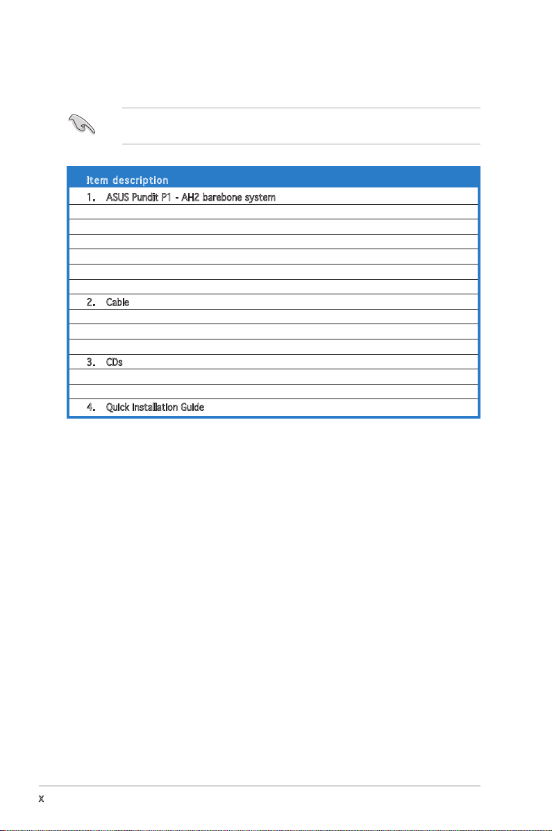
System package contents
Check your Pundit P1 - AH2 system package for the following items.
If any of the items is damaged or missing, contact your retailer
immediately.
Ite m d escri p t i on
1. ASUS Pundit P1 - AH2 barebone system with
• ASUS motherboard
• CPU fan and heatsink assembly
• CompactFlash card reader
• 3-in-1 storage card reader
• PCI riser card
• 250W power supply unit
2. Cable
• Power cable and plug
• Serial ATA power cable and signal cable
• IDE cable
3. CDs
• Support CD
• Recover PRO CD
4. Quick installation Guide
Page 11
ASUS Pundit P1-AH2
Chapter 1
System introduction
This chapter gives a general
description of the ASUS
Pundit P1-AH2. The chapter lists
the system features including
introduction on the front and rear
panel, and internal components.
Page 12
1-2
Chapter 1: System introduction
1.1 Welcome!
Thank you for choosing the ASUS Pundit P1-AH2!
The ASUS Pundit P1-AH2 is an all-in-one barebone system with a versatile
home entertainment feature.
The system comes in a stylish casing and powered by the ASUS
motherboard that supports the AMD® Athlon64, AMD® Athlon 64 FX, AMD®
Sempron, or AMD® Athlon 64 X2 processor.
The system supports up to 2 GB of system memory using
DDR2-800/667/533/400 DIMMs, high-resolution graphics via integrated
graphics controller, Serial ATA, USB 2.0, and 6-channel audio.
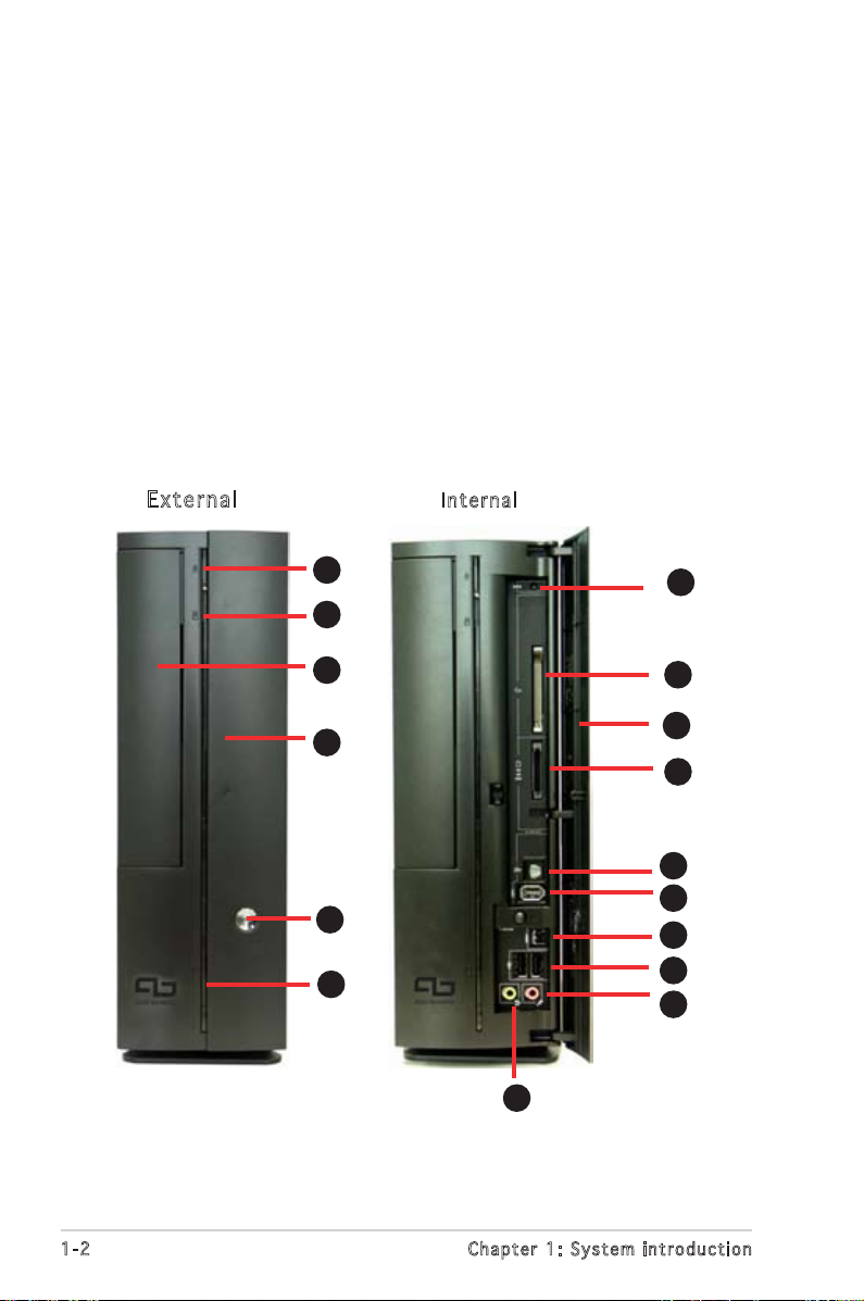
1.2 Front panel
E x ter n al
In t e r nal
1
2
3
4
5
6
7
8
1
2
3
4
5
6
10
9
Page 13
1-3
ASUS Pundit P1-AH2
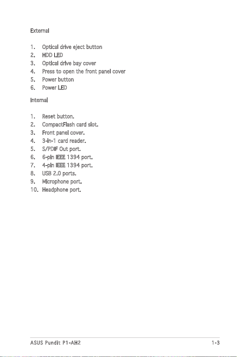
External
1. Optical drive eject button
2. HDD LED
3. Optical drive bay cover
4. Press to open the front panel cover
5. Power button
6. Power LED
Internal
1. Reset button.
2. CompactFlash card slot.
3. Front panel cover.
4. 3-in-1 card reader.
5. S/PDIF Out port.
6. 6-pin IEEE 1394 port.
7. 4-pin IEEE 1394 port.
8. USB 2.0 ports.
9. Microphone port.
10. Headphone port.
Page 14
1-4
Chapter 1: System introduction
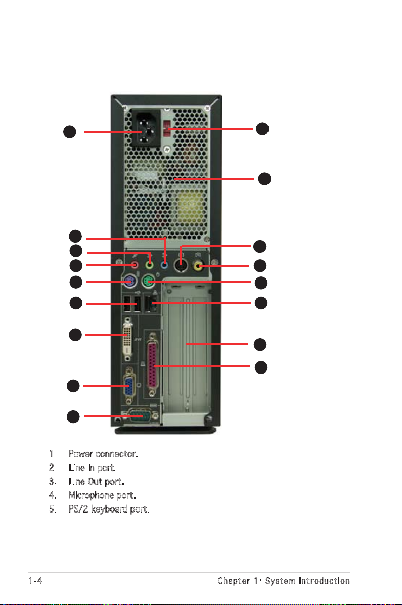
1.3 Rear panel
The system rear panel includes the power connector and several I/O ports
that allow convenient connection of devices.
1. Power connector.
2. Line In port.
3. Line Out port.
4. Microphone port.
5. PS/2 keyboard port.
10
11
12
1
2
4
5
6
7
8
9
3
14
15
13
16
17
Page 15
1-5
ASUS Pundit P1-AH2
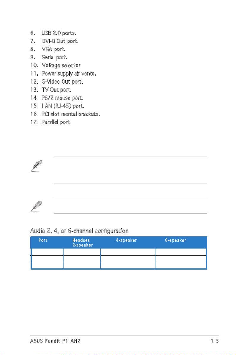
6. USB 2.0 ports.
7. DVI-D Out port.
8. VGA port.
9. Serial port.
10. Voltage selector
11. Power supply air vents.
12. S-Video Out port.
13. TV Out port.
14. PS/2 mouse port.
15. LAN (RJ-45) port.
16. PCI slot mental brackets.
17. Parallel port.
Refer to the audio configuration table below for the function of the audio
ports in 2, 4, or 6-channel configuration.
Audio 2, 4, or 6-channel configuration
Light Blue Line In Surround Out Surround Out
Lime Line Out Front Speaker Out Front Speaker Out
Pink Mic In Mic Center/Bass
Por t He a d s et 4-s p e a ker 6-s p e a ker
2-spe a k e r
The systemʼs power supply unit has a115 V/230 V voltage selector
switch located near the power connector. Use this switch to select the
correct system input voltage according to the voltage supply in your
area.
Page 16
1-6
Chapter 1: System introduction
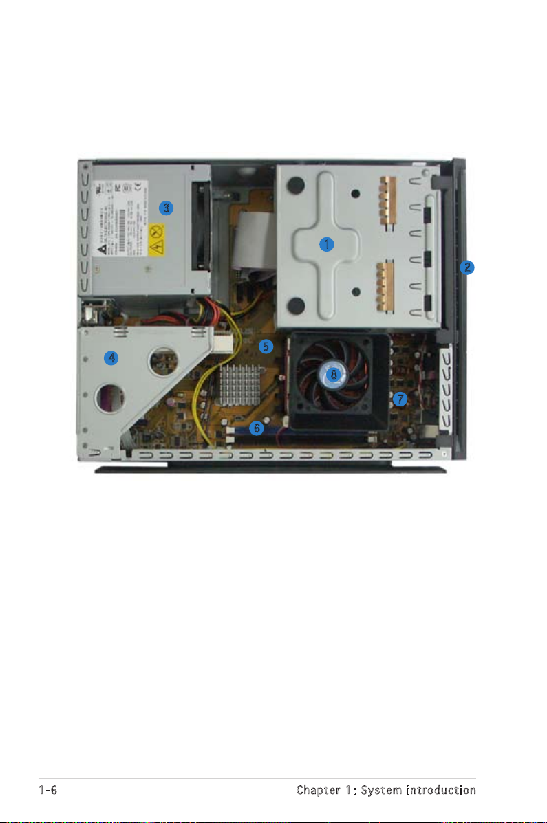
1.4 Internal components
The illustration below is the internal view of the system when you remove
the top cover and the power supply unit. The installed components are
labeled for your reference. Proceed to Chapter 2 for instructions on
installing additional system components.
1. 5.25-inch optical drive and 3.5
inch hard disk drive cage
2. Front penel cover
3. Power supply unit
4. PCI card riser bracket
(connected to the
motherboard PCI slot)
5. ASUS motherboard
6. DIMM sockets
7. CPU socket
8. CPU fan and heatsink assembly
6
1
2
3
4
7
8
5
Page 17

Chapter 2
Basic installation
This chapter provides step-by-step
instructions on how to install
components in the system.
Page 18
2-2
Chapter 2: Basic installation
2.1 Preparation
Before you proceed, make sure that you have all the components you plan
to install in the system.
Bas i c c omp o ne n ts t o i nst a ll
1. Central Processing Unit (CPU)
2. DDR2 Dual Inline Memory Module (DIMM)
3. Expansion card(s)
4. Hard disk drive
5. Optical drive
Too l
Phillips (cross) screw driver
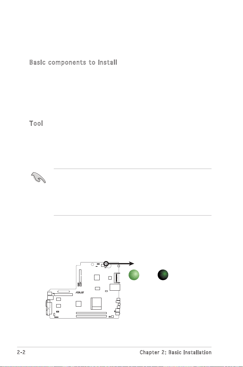
The motherboard comes with an onboard standby power LED. This LED
lights up to indicate that the system is ON, in sleep mode or in soft-off
mode, and not powered OFF. Unplug the power cable from the power outlet
and make sure that the standby power LED is OFF before installing any
system component.
•
Use a grounded wrist strap or touch a safely grounded object or
a metal object, such as the power supply case, before handling
components to avoid damaging them due to static electricity.
•
Hold components by the edges to avoid touching the ICs on them.
•
Whenever you uninstall any component, place it on a grounded
antistatic pad or in the bag that came with the component.
2.2 Before you proceed
Take note of the following precautions before you install components into
the system.
R
Onboard LED
SB_PWR
ON
Standby
Power
OFF
Powered
Off
Page 19
2-3
ASUS Pundit P1-AH2
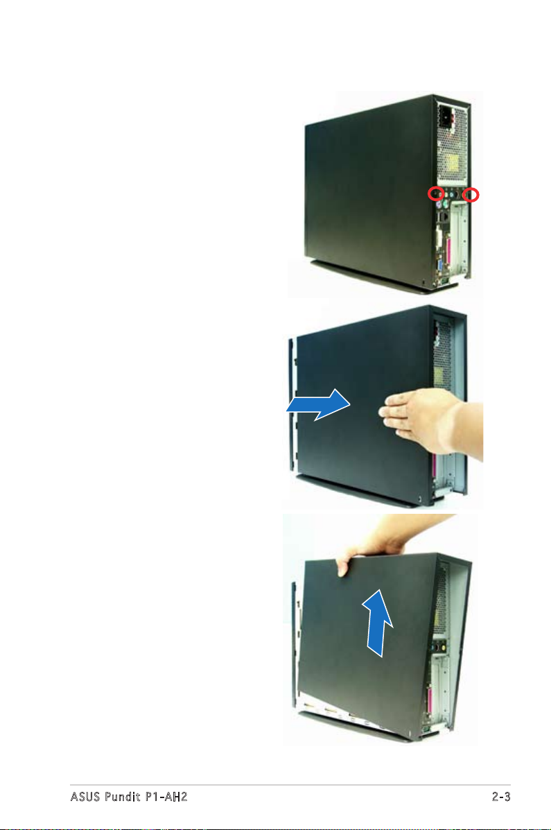
2.3 Removing the side cover
1. Remove the cover screws.
Keep the screws for later use.
2. Pull the cover slightly toward
the rear panel.
3. Lift the cover, then set aside.
Page 20
2-4
Chapter 2: Basic installation
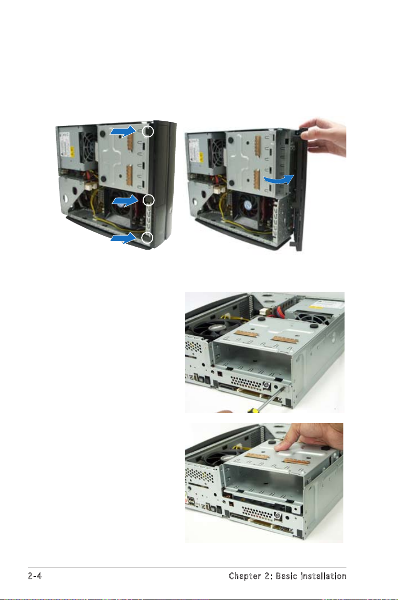
2.4 Removing the front panel cover
1. Lift the front panel cover hooks outward.
2. Carefully remove the front panel cover, then set it aside.
2.5 Removing the storage drive assembly
1. Lay the system on its
side, then locate and
remove three storage
drive assembly screws.
2. Lift the storage drive
assembly, then set
aside.
Page 21
2-5
ASUS Pundit P1-AH2
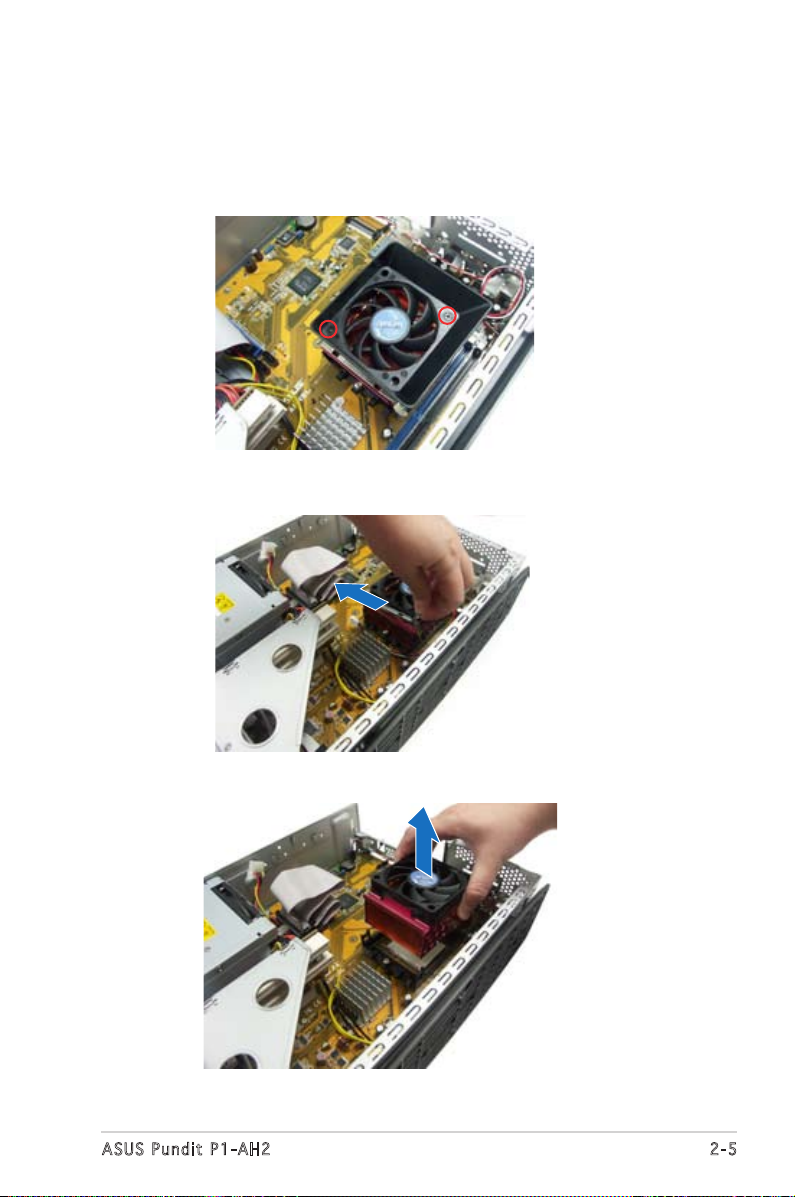
2.6 Removing the CPU fan and heatsink
1. Disconnect the CPU fan cable.
2. Remove two screws securing the blower to the CPU fan. Set the
blower aside.
3. Unhook and slide out the metal clips that secure the fan and heatsink
assembly to the retention module.
4. Lift the CPU fan and heatsink assembly, then set aside.
Page 22
2-6
Chapter 2: Basic installation
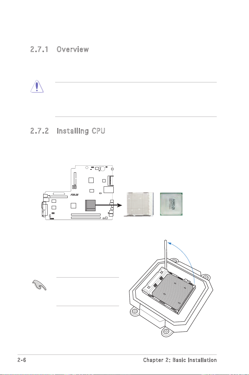
2.7 Central Processing Unit (CPU)
2.7 .1 Ove rv ie w
The motherboard comes with a 940-pin AM2 socket designed for the AMD
Athlon™ 64 X2/Athlon™ 64/Sempron™ processor.
The AM2 socket has a different pinout from the 940-pin socket
designed for the AMD Opteron™ processor. Make sure you use a CPU
that is designed for the AM2 socket. The CPU fits in only one correct
orientation. DO NOT force the CPU into the socket to prevent bending
the pins the CPU!
2.7 .2 Ins ta ll ing C PU
To install a CPU:
1. Locate the CPU socket on the motherboard.
R
CPU Socket AM2
2. Unlock the socket by pressing
the lever sideways, then lift it
up to a 90º angle.
Make sure that the socket
lever is lifted up to a 90º
angle; otherwise, the CPU
will not fit in completely.
Page 23
2-7
ASUS Pundit P1-AH2
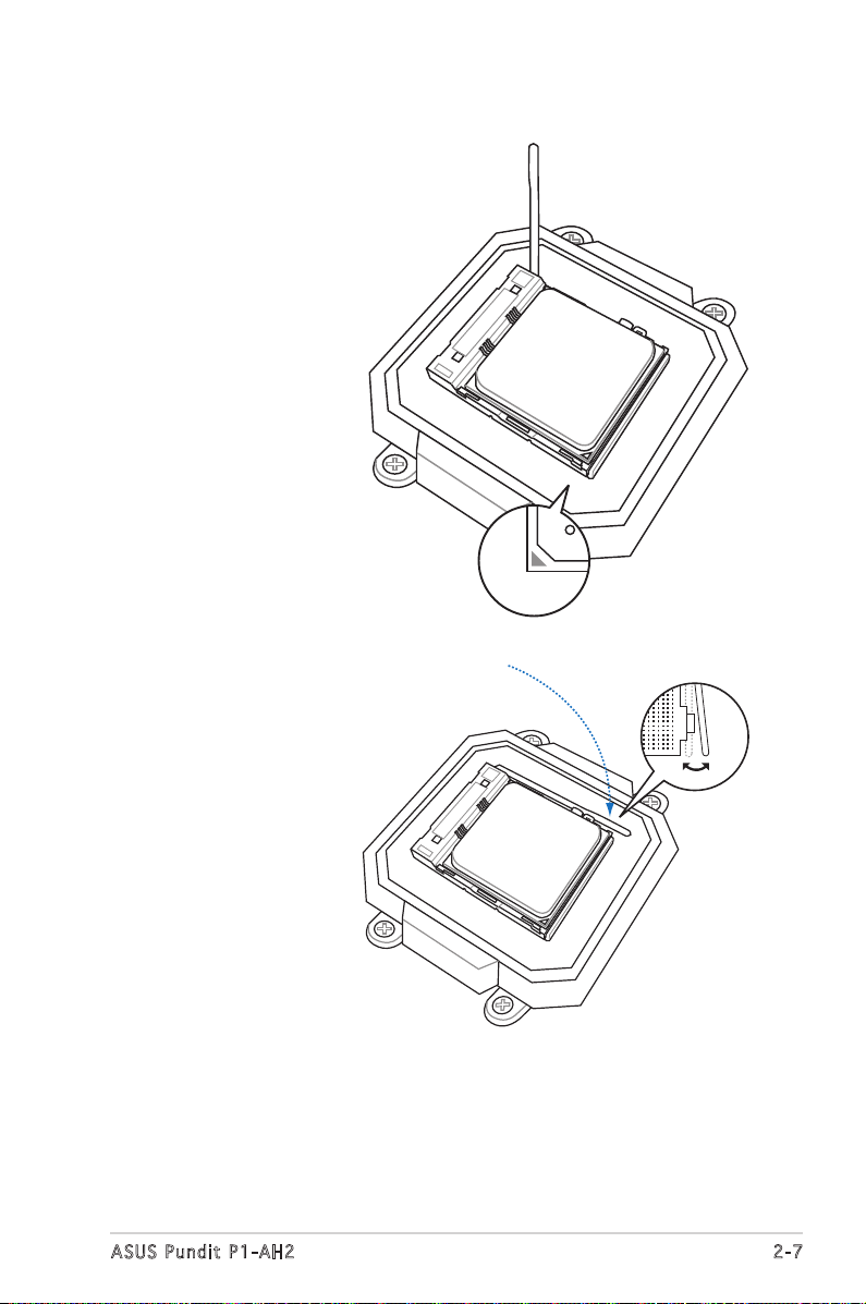
3. Position the CPU
above the socket
such that the
CPU corner with
the gold triangle
matches the
socket corner with
a small triangle.
4. Carefully insert
the CPU into the
socket until it fits
in place.
5. When the CPU is in
place, push down
the socket lever
to secure the CPU.
The lever clicks
on the side tab to
indicate that it is
locked.
6. Install a CPU
heatsink and fan
following the
instructions that
came with the
heatsink package.
Page 24
2-8
Chapter 2: Basic installation
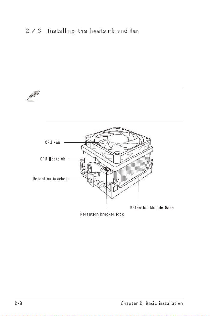
2.7 .3 Ins ta ll ing t he he at si nk an d fan
The AMD Athlon™ 64/AMD Athlon™ 64 X2/ AMD Sempron™ processor
requires a specially designed heatsink and fan assembly to ensure optimum
thermal condition and performance.
Follow these steps to install the CPU heatsink and fan.
1. Place the heatsink on top of the installed CPU, making sure that the
heatsink fits properly on the retention module base.
• The retention module base is already installed on the motherboard
upon purchase.
• You do not have to remove the retention module base when
installing the CPU or installing other motherboard components.
CPU F a n
CPU H e atsin k
Ret e n t ion b r a c ket
Ret e n t ion b r a c ket l o c k
Ret e n t ion M o d u le Ba s e
Page 25
2-9
ASUS Pundit P1-AH2
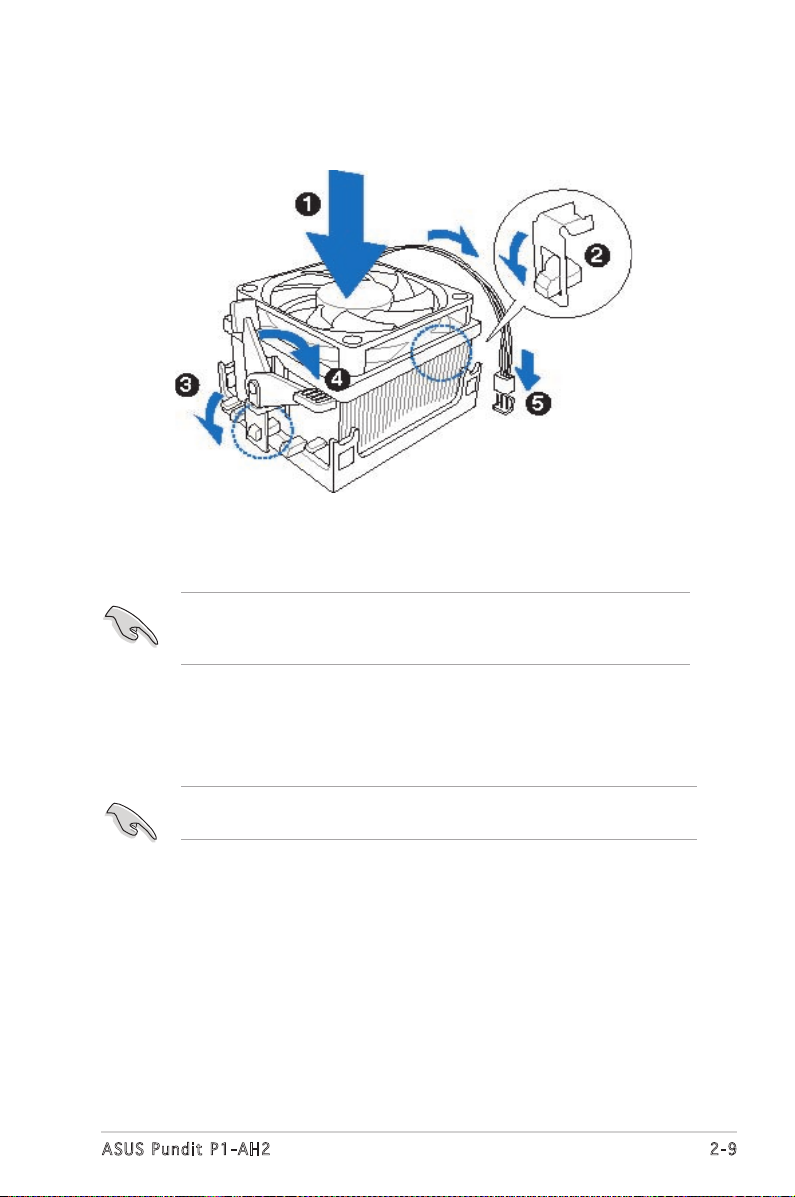
2. Attach one end of the retention bracket to the retention module base.
3. Align the other end of the retention bracket (near the retention
bracket lock) to the retention module base. A clicking sound denotes
that the retention bracket is in place.
Make sure that the fan and heatsink assembly perfectly fits the
retention mechanism module base, otherwise you cannot snap the
retention bracket in place.
4. Push down the retention bracket lock on the retention mechanism to
secure the heatsink and fan to the module base.
5. When the fan and heatsink assembly is in place, connect the CPU fan
cable to the connector on the motherboard labeled CPU_FAN.
Do not forget to connect the CPU fan connector! Hardware monitoring
errors can occur if you fail to plug this connector.
Page 26

2-8
Chapter 2: Basic installation
2.8 Installing a DIMM
The system motherboard comes with two Double Data Rate 2 (DDR2) Dual
Inline Memory Module (DIMM) sockets.
The following figure illustrates the location of the sockets:
• Install only identical (the same type and size) DDR2 memory
modules.
• Install only ASUS-certified memory modules. Refer to the DDR2
Qualified Vendors List on the next page for details. Visit the ASUS
website for the latest DDR2 QVL.
• Always install DIMMs with the same CAS latency. For optimum
compatibility, we recommend that you obtain memory modules from
the same vendor.
2.8 .1 Me m or y co n fi gu ra t io ns
You may install up to 2 GB system memory using 256 MB, 512 MB, and 1
GB DDR2 DIMMs.
R
240-pin DDR2 DIMM Sockets
DIMM_A1
DIMM_B1
112 Pins128 Pins
Page 27
2-9
ASUS Pundit P1-AH2
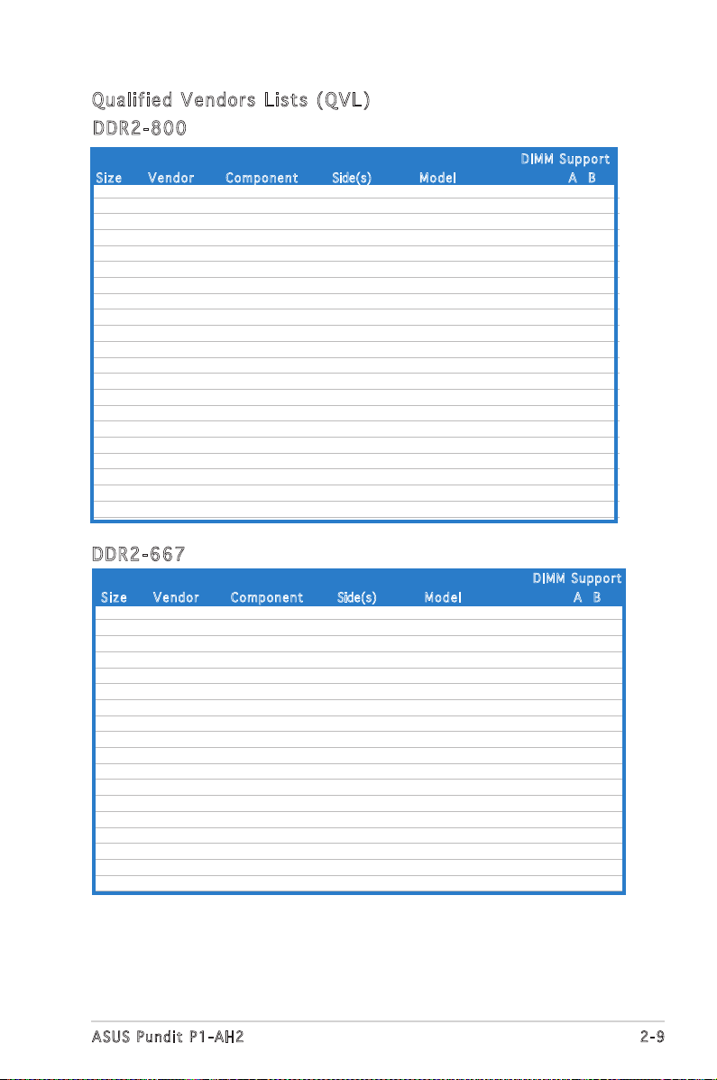
Qua l if i ed V en d ors Li s ts ( QV L )
DDR 2 -66 7
512MB KINGSTON E5108AE-6E-E SS KVR667D2N5/512 V V
1024MB KINGSTON E5108AE-6E-E DS KVR667D2N5/1G V V
512MB KINGSTON E5108AE-6E-E SS KVR667D2E5/512 V V
256MB KINGSTON HYB18T256800AF3 SS KVR667D2N5/256 V V
256MB SAMSUNG K4T51163QC-ZCE6 SS M378T3354CZ0-CE6 V V
512MB SAMSUNG ZCE6K4T51083QC SS M378T6553CZ0-CE6 V V
1024MB SAMSUNG ZCE6K4T51083QC DS M378T2953CZ0-CE6 V V
256MB Qimonda HYB18T512160AF-3S SS HYS64T32000HU-3S-A V V
512MB Qimonda HYB18T512800AF3S SS HYS64T64000HU-3S-A V V
1024MB Qimonda HYB18T512800AF3S DS HYS64T128020HU-3S-A V V
256MB Qimonda HYB18T512160BF-3S SS HYS64T32000HU-3S-B V
512MB Qimonda HYB18T512800BF3S SS HYS64T64000HU-3S-B V V
1024MB Qimonda HYB18T512800BF3S DS HYS64T128020HU-3S-B V V
256MB ELPIDA E2508AB-6E-E SS EBE25UC8ABFA-6E-E V V
512MB ELPIDA E5108AE-6E-E SS EBE51UD8AEFA-6E-E V V
512MB A-DATA AD29608A8B-3EG SS M20AD5Q3H3163J1C52 V V
512MB Transcend E5108AE-6E-E SS TS64MLQ64V6J V V
1024MB Transcend E5108AE-6E-E DS TS128MLQ64V6J V V
DDR 2 -80 0
512MB KINGSTON K4T51083QC SS KVR800D2N5/512 V V
1024MB KINGSTON K4T51083QC DS KVR800D2N5/1G V
512MB SAMSUNG EDD339XX SS M378T6553CZ3-CE7 V V
256MB SAMSUNG K4T51163QC-ZCE7 SS M378T3354CZ3-CE7 V V
512MB Qimonda HYB18T256800AF25F DS HYS64T64020HU-25F-A V V
512MB Hynix HY5PS12821BFP-S5 SS HYMP564U64BP8-S5 V V
1024MB Hynix HY5PS12821BFP-S5 DS HYMP512U64BP8-S5 V
512MB MICRON 5JAIIZ9DQQ SS MT8HTF6464AY-80EA3 V V
1024MB MICRON 5JAIIZ9DQQ DS MT16HTF12864AY-80EA3 V
512MB MICRON 5ZD22D9GKX SS MT8HTF6464AY-80ED4 V
1024MB MICRON 5ZD22D9GKX DS MT16HTF12864AY-80ED4 V V
512MB MICRON 6CD22D9GKX SS MT8HTF6464AY-80ED4 V V
1024MB MICRON 6CD22D9GKX DS MT16HTF12864AY-80ED4 V
512MB CORSAIR Heat-Sink Package SS CM2X512A-6400 V V
1024MB CORSAIR Heat-Sink Package DS CM2X1024-6400C4 V V
512MB A-DATA N/A SS M2OAD6G3H3160J1E52 V V
512MB A-DATA AD29608A8A-25EG SS M20AD6G3H3160I1E5E V
1024MB Crucial Heat-Sink Package DS BL12864AA804.16FD V V
256MB Apacer E2508AB-GE-E SS 78.81091.420 V V
512MB Apacer E2508AB-GE-E DS 78.91091.420 V V
256MB TwinMOS E2508AB-GE-E SS 8G-24IK2-EBT V V
Siz e Ve n d o r Co m pone n t Side(s) M o del A B
Siz e Ve n d o r Co m pone n t Side(s) M o del A B
DIM M S uppor t
DIM M S uppor t
Page 28
2-10
Chapter 2: Basic installation
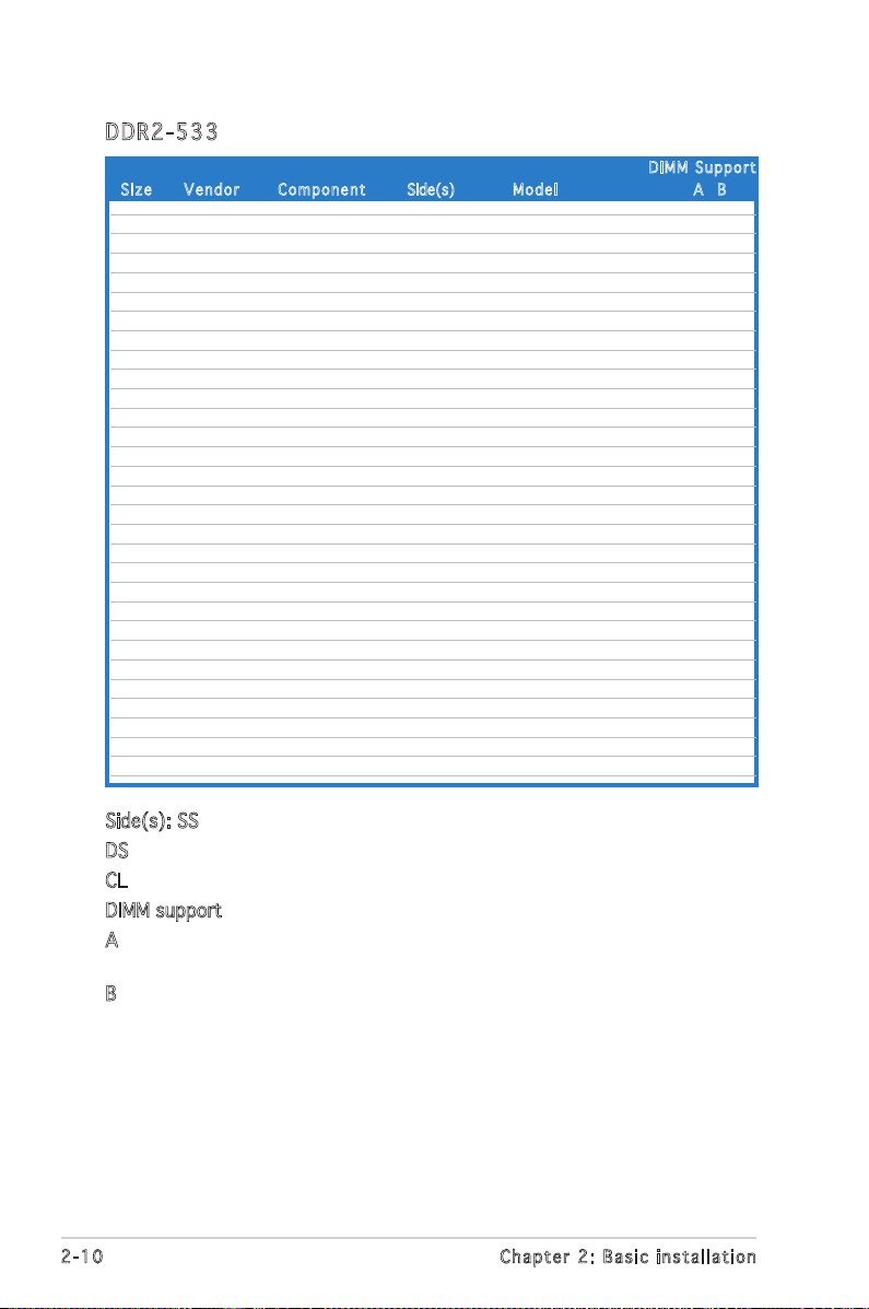
Side(s): SS - Single-sided
DS - Double-sided
CL: CAS Latency
DIMM support:
A -Supports one module inserted into either slot, in Single-channel memory
configuration.
B -Supports one pair of modules inserted into both slots as one pair of
Dual-channel memory configuration.
DDR 2 -53 3
Siz e Ve n d o r Co m pone n t Side(s) M o del A B
DIM M S uppor t
256MB KINGSTON E5116AF-5C-E SS KVR533D2N4/256 V V
512MB KINGSTON HYB18T512800AF37 SS KVR533D2N4/512 V V
1024MB KINGSTON 5YDIID9GCT DS KVR533D2N4/1G V V
512MB Infineon HYB18T512800AC37 SS HYS64T64000GU-3.7-A V V
256MB Infineon HYB18T512160AF-3.7 SS HYS64T32000HU-3.7-A V V
512MB Infineon HYB18T512800AF37 SS HYS64T64000HU-3.7-A V V
1024MB Infineon HYB18T512800AF37 DS HYS64T128020HU-3.7-A V V
2048MB Infineon HYB18T1G800AF-3.7 DS HYS64T256020HU-3.7-A V V
256MB Infineon HYB18T5121608BF-3.7 SS HYS64T32000HU-3.7-B V V
512MB Infineon HYB18T512800BF37 SS HYS64T64000HU-3.7-B V V
1024MB Infineon HYB18T512800BF37 DS HYS64T128020HU-3.7-B V V
512MB Hynix HY5PS12821F-C4 S HYMP564U648-C4 V V
1024MB Hynix HY5PS12821F-C4 DS HYMP512U648-C4 V V
1024MB Hynix HY5PS12821FP-C4 DS HYMP512U648-C4 V V
512MB Hynix HY5PS12821AFP-C3 SS HYMP564U64AP8-C3 V V
1024MB Hynix HY5PS12821AFP-C3 DS HYMP512U64AP8-C3 V V
512MB ELPIDA E5108AB-5C-E SS EBE51UD8ABFA-5C V V
512MB ELPIDA E5108AB-5C-E SS EBE51UD8ABFA-5C-E V V
1024MB ELPIDA E5108AB-5C-E DS EBE11UD8ABFA-5C-E V V
2048MB ELPIDA E1108AA-5C-E DS EBE21EE8AAFA-5C-E V
256MB CORSAIR MIII0051832M8CEC SS VS256MB533D2 V
512MB CORSAIR MI110052432M8CEC DS VS512MB533D2 V V
256MB Apacer E5116AB-5C-E SS 78.81077.420 V V
256MB KINGMAX E5116AB-5C-E SS KLBB68F-36EP4 V V
512MB KINGMAX E5108AE-5C-E SS KLBC28F-A8EB4 V V
1024MB KINGMAX E5108AE-5C-E DS KLBD48F-A8EB4 V V
512MB KINGMAX KKEA88E4AAK-37 SS KLBC28F-A8KE4 V V
1024MB KINGMAX 5MB22D9DCN DS KLBD48F-A8ME4 V V
512MB Transcend K4T51083QB-GCD5 SS TS64MLQ64V5J V V
1024MB Transcend K4T51083QB-GCD5 DS TS128MLQ64V5J V V
Page 29

2-11
ASUS Pundit P1-AH2
2.8 .3 Rem ov in g a D DR 2 D IM M
Follow these steps to remove a DIMM.
1. Simultaneously press the
retaining clips outward to
unlock the DIMM.
2. Remove the DIMM from the socket.
Support the DIMM lightly with your fingers when pressing the retaining
clips. The DIMM might get damaged when it flips out with extra force.
2.8 .2 Ins ta ll ing a D DR2 D IM M
3. Firmly insert the DIMM into the
socket until the retaining clips
snap back in place and the DIMM
is properly seated.
1. Unlock a DDR2 DIMM socket
by pressing the retaining clips
outward.
2. Align a DIMM on the socket
such that the notch on the
DIMM matches the break on
the socket.
Loc k e d Reta i n i ng Cl i p
Make sure to unplug the power supply before adding or removing DIMMs
or other system components. Failure to do so may cause severe damage
to both the motherboard and the components.
A DDR2 DIMM is keyed with a notch so that it fits in only one direction.
DO NOT force a DIMM into a socket to avoid damaging the DIMM.
DDR 2 D IMM n o t c h
1
2
1
3
Unl o c k ed re t a i ning c l i p
1
1
DDR 2 D IMM n o t c h
2
Page 30

2-12
Chapter 2: Basic installation
2.9 Expansion slots
In the future, you may need to install expansion cards. The following
sub-sections describe the slots and the expansion cards that they support.
Make sure to unplug the power cord before adding or removing
expansion cards. Failure to do so may cause you physical injury and
damage motherboard components.
2.9 .1 PCI s lo ts
This system has two PCI slot that supports cards such as a LAN card, SCSI
card, USB card, and other cards that comply with PCI specifications.
2.9 .2 Ins ta ll ing a n exp an si on ca rd
1. Lift the PCI riser card assembly.
Page 31

2-13
ASUS Pundit P1-AH2
2. Remove the metal cover opposite the slot that you intend to use.
3. Insert the card connector to the slot, then press the card firmly
until it fits in place. Secure the card with a screw.
4. Reinstall the PCI riser card assembly. Make sure that the riser card
connector sits properly on the motherboard PCI slot.
Page 32

2-14
Chapter 2: Basic installation
2.10 Installing an optical drive
Follow these steps to install an optical drive:
1. Turn the storage drive assembly upside down with the 3.5-inch bay on
top of the 5.25-inch bay.
2. Insert the optical drive upside down to the 5.25-inch bay, then secure
it with two screws on both sides.
3. Turn the storage drive assembly, insert the hard disk drive upside
down to the 3.5-inch bay, then secure it with two screws on both
sides.
Page 33

2-15
ASUS Pundit P1-AH2
2.11 Reinstalling the storage drive
assembly
Before reinstalling the storage drive assembly, connect the IDE / SATA and
power plugs to the IDE / SATA and power connectors at the back of
the drives.
1. Connect the black plug of the IDE cable to the optical drive, then the
gray plug to the hard disk drive. If you have the SATA HDD, connect
the SATA cable to the SATA HD.
2. Connect the 4-pin power plugs to the power connectors at the back
of the drives.
3. Install the storage drive assembly to the chassis.
4. Secure the storage drive assembly with three screws.
Page 34

2-16
Chapter 2: Basic installation
2.12 Installing the foot stand
2.13 Reinstalling the front panel cover and
the cover
1. Match the foot stand
hooks to the holes on
the chassis.
2. Pull the foot stand to
the direction of the
arrow until the lock
clicks in place.
To remove the foot stand, lift the lock, then slightly push the foot stand to
the direction of the rear panel until it disengages from the chassis.
Refer to the section of Removing the front panel cover and follow the
instructions in reverse.
Refer to the section of Removing the cover and follow the instructions in
reverse.
Page 35

ASUS Pundit P1-AH2
Chapter 3
Starting up
This chapter helps you power up
the system and install drivers and
utilities from the support CD.
Page 36

3-2
Chapter 3: Starting up
3.1 Installing an operating system
The barebone system supports Windows® 2000/XP operating systems
(OS). Always install the latest OS version and corresponding updates so
you can maximize the features of your hardware.
3.3 Support CD information
The support CD that came with the system contains useful software and
several utility drivers that enhance the system features.
3.2 Powering up
Press the system power button ( ) to enter the OS.
Pre s s to tu r n ON th e s y stem
Because motherboard settings and hardware options vary, use the setup
procedures presented in this chapter for general reference only. Refer to
your OS documentation for more information.
•
Screen display and driver options may not be the same for different
operating system versions.
•
The contents of the support CD are subject to change at any time
without notice. Visit the ASUS website for updates.
Page 37

3-3
ASUS Pundit P1-AH2
3.3 .1 Run ni ng th e su ppo rt C D
To begin using the support CD, place the CD in your optical drive. The
CD automatically displays the Drivers menu if Autorun is enabled in your
computer.
If Autorun is NOT enabled in your computer, browse the contents of the
support CD to locate the file ASSETUP.EXE from the BIN folder.
Double-click the ASSETUP.EXE to run the CD.
Cli c k an it e m to in s t a ll
Cli c k an ic o n to
dis p l a y sup p o r t
CD/ m o t herbo a r d
inf o r m ation
AMD Co o lʼn ʼ Qu i et D ri v er
Installs the AMD CoolʼnʼQuiet driver.
NVI D IA nFo r ce Chi p se t Dr i ve r
Installs the NVIDIA nForce chipset driver.
NVI D IA GeF o rc e 61 X 0 D isp l ay Dri v er
Installs the NVIDIA GeForce 61X0 display driver.
Rea l te k Au d io Dri v er
Allows you to install the Realtek audio driver.
USB 2.0 Dr i ver
Installs the USB 2.0 driver file that came with the utility for details.
Page 38

3-4
Chapter 3: Starting up
3.3 .2 Uti li ti es me nu
The Utilities menu shows the applications and other software that the
motherboard supports.
ASU S P C Pr o be II
This smart utility monitors the fan speed, CPU temperature, and system
voltages, and alerts you of any detected problems. This utility helps you keep
your computer in healthy operating condition.
ASU S U p dat e
The ASUS Update utility allows you to update the motherboard BIOS in a
Windows® environment. This utility requires an Internet connection either through
a network or an Internet Service Provider (ISP).
ASU S C o olʼ n ʼQ u iet Uti lit y
Installs the ASUS CoolʼnʼQuiet Utility.
ADO B E A cro b at Rea d er V7. 0
Installs the Adobe® Acrobat® Reader V7.0 that allows you to open, view, and
print documents in Portable Document Format (PDF).
ASU S S c ree n S a ver
Installs the ASUS screen saver.
Mic r os o ft D ir e ctX 9. 0 c
Installs the Microsoft® DirectX 9.0c driver.
Page 39

3-5
ASUS Pundit P1-AH2
3.4 Software information
Most of the applications in the support CD have wizards that will
conveniently guide you through the installation. View the online help or
readme file that came with the software for more information.
3.3 .3 ASU S Co nta ct i nfo rm at ion
Click the Contact tab to display the ASUS contact information. You can also
find this information on the inside front cover of this user guide.
3.4 .1 A SUS P C Pro be I I
PC Probe II is a utility that monitors the computerʼs vital components
and alerts you of any problem with these components. PC Probe II senses
fan rotations, CPU temperature, and system voltages, among others. PC
Probe II is software-based, allowing you to start monitoring your computer
the moment you turn it on. With this utility, you are assured that your
computer is always at a healthy operating condition.
USB 2 .0 Car d Re ade r So ftw a re
Installs the USB2.0 card reader software.
Ant i -v i rus ut i lit y
The anti-virus application scans, identifies, and removes computer viruses. View
the online help for detailed information.
Page 40

3-6
Chapter 3: Starting up
Ins t al l ing PC Pro b e I I
To install PC Probe II on your computer:
1. Place the support CD to the optical drive. The Drivers installation tab
appears if your computer has an enabled Autorun feature.
Cli c k to cl o s e the
Pre f e r ence p a n el
2. Click the Utilities tab, then click ASUS PC Probe II.
3. Follow the screen instructions to complete installation.
Lau n ch i ng P C P rob e I I
You can launch the PC Probe II right after installation or anytime from the
Windows® desktop.
To launch the PC Probe II from the Windows® desktop, click Start > All
Programs > ASUS > PC Probe II. The PC Probe II main window appears.
After launching the application, the PC Probe II icon appears in the
Windows® taskbar. Click this icon to close or restore the application.
Usi n g P C P r ob e II
Main window
The PC Probe II main window allows
you to view the current status of
your system and change the utility
configuration. By default, the main
window displays the Preference
section. You can close or restore
the Preference section by clicking
on the triangle on the main window
right handle.
If Autorun is not enabled in your computer, browse the contents of the
support CD to locate the setup.exe file from the ASUS PC Probe II folder.
Double-click the setup.exe file to start installation.
Page 41

3-7
ASUS Pundit P1-AH2
But t o n Fu n c t ion
Opens the Configuration window
Opens the Report window
Opens the Desktop Management Interface window
Opens the Peripheral Component Interconnect window
Opens the Windows Management Instrumentation window
Opens the hard disk drive, memory, CPU usage window
Shows/Hides the Preference section
Minimizes the application
Closes the application
Sensor alert
When a system sensor detects a problem, the main window right handle
turns red, as the illustrations below show.
When displayed, the monitor panel for that sensor also turns red. Refer to
the Monitor panels section for details.
Pre f er e nce s
You can customize the application using the
Preference section in the main window. Click
the box before each preference to activate or
deactivate.
Page 42

3-8
Chapter 3: Starting up
Har d wa r e m o ni t or p an e ls
The hardware monitor panels display the current value of a system sensor
such as fan rotation, CPU temperature, and voltages.
The hardware monitor panels come in two display modes: hexagonal (large)
and rectangular (small). When you check the Enable Monitoring Panel
option from the Preference section, the monitor panels appear on your
computerʼs desktop.
Changing the monitor panels position
To change the position of the monitor panels on the desktop,
click the arrow down button of the Scheme options, then
select another position from the list box. Click OK when
finished.
Moving the monitor panels
All monitor panels move together using
a magnetic effect. If you want to detach
a monitor panel from the group, click the
horseshoe magnet icon. You can now move
or reposition the panel independently.
Adjusting the sensor threshold value
You can adjust the sensor threshold
value in the monitor panel by clicking
the arrow buttons. You can also
adjust the threshold values using the
Config window.
You cannot adjust the sensor threshold
values in a small monitoring panel.
Lar g e displ a y
Sma l l displ a y
Cli c k to
inc r e a se
val u e
Cli c k to
dec r e a se
val u e
Page 43

3-9
ASUS Pundit P1-AH2
Monitoring sensor alert
The monitor panel turns red when a component value exceeds or is lower
than the threshold value. Refer to the illustrations below.
Lar g e displ a y
Sma l l displ a y
WMI br o wse r
Click to display the
WMI (Windows Management
Instrumentation) browser. This
browser displays various Windows®
management information. Click an
item from the left panel to display
on the right panel. Click the plus
sign (+) before WMI Information to
display the available information.
You can enlarge or reduce the browser size by dragging the bottom right
corner of the browser.
DMI br o wse r
Click to display the DMI
(Desktop Management Interface)
browser. This browser displays
various desktop and system
information. Click the plus sign (+)
before DMI Information to display
the available information.
Page 44

3-10
Chapter 3: Starting up
PCI br o wse r
Click to display the
PCI (Peripheral Component
Interconnect) browser. This
browser provides information on
the PCI devices installed on your
system. Click the plus sign (+)
before the PCI Information item to
display available information.
Usa g e
The Usage browser displays real-time information on the CPU, hard disk
drive space, and memory usage. Click to display the Usage browser.
CPU usage
The CPU tab displays real-time CPU
usage in line graph representation.
If the CPU has an enabled HyperThreading, two separate line graphs
display the operation of the two
logical processors.
Hard disk drive space usage
The Hard Disk tab displays the used
and available hard disk drive space.
The left panel of the tab lists all
logical drives. Click a hard disk drive
to display the information on the
right panel. The pie chart at the
bottom of the window represents
the used (blue) and the available
HDD space.
Page 45

3-11
ASUS Pundit P1-AH2
Memory usage
The Memory tab shows both used
and available physical memory.
The pie chart at the bottom of the
window represents the used (blue)
and the available physical memory.
Con f ig u rin g P C Pr o be II
Click to view and adjust the sensor threshold values.
The Config window has two tabs: Sensor/Threshold and Preference. The
Sensor/Threshold tab enables you to activate the sensors or to adjust the
sensor threshold values. The Preference tab allows you to customize sensor
alerts, change temperature scale, or enable the Q-Fan feature.*
*Av a i l able o n some m o t herbo a r d s onl y .
Loa d s the d e f a u lt
thr e s h old v a l u es
for e a ch se n s o r
App l i e s you r
cha n g e s
Can c e l s or
ign o r e s you r
cha n g e s
Lo ads y our s ave d
co nfigu ratio n
Sav e s your
con f i g urati o n
Page 46

3-12
Chapter 3: Starting up
3.4 .2 D TS fu nc tio n
When click the icon or insert the device into the phone jack, the manager
will poop out. You can click the dts Neo: PC and dts Interactive buttons to
initiate those functions a shown below.
DTS NEO: PC
Refer to the appendix of this section on page 3-15 for more
information about DTS function.
DTS Connect is embedded in the audio drivers. After the driver installed,
there is “Realtek HD Audio Manager” icon in the desktop manual bar (see
figure below).
“DT S C O NNECT ” , “ DTS I N T E R ACTIV E ” a nd “D T S N EO: P C ” a re tr a d e m ark o f
DTS , I n c . “DT S ” i s a r e g i s tered t r a demar k o f DTS, I n c .
Page 47

3-13
ASUS Pundit P1-AH2
DTS Interactive
When DTS Interactive is enabled, only digital audio output(S/
PDIF) is working, and you will not hear sound from analog
speaker or headphone.
“DT S C O NNECT ” , “ DTS I N T E R ACTIV E ” a nd “D T S N EO: P C ” a re tr a d e m ark o f
DTS , I n c . “DT S ” i s a r e g i s tered t r a demar k o f DTS, I n c .
Page 48

3-14
Chapter 3: Starting up
Detailed Settings
“DTS C O N NECT” , “ D TS IN T E R A CTIVE ” a n d “DT S N E O: PC ” a r e tra d e m a rk of
DTS , I n c . “DT S ” i s a r e g i s tered t r a demar k o f DTS, I n c .
Page 49

3-15
ASUS Pundit P1-AH2
App en di x: DT S fun ct io n
DTS ConnectTM is the latest product from DTS that turns your PC into an
action packed entertainment experience that surrounds you in sound.
DTS Connect includes DTS Neo:PCTM and DTS InteractiveTM to bring new
sound capabilities to your PC. DTS Neo:PC converts stereo sources into
7.1 multichannel sound, and DTS Interactive enables you to re-encode your
multichannel sources into DTS 5.1 channel surround sound for playback
through your home entertainment system.
DTS c o n nect
DTS Connect - Stereo is boring, surround sound is fun!
DTS N E O : PC
DTS Neo:PC – Listen to your Stereo Movies and Music in
exciting Surround Sound!
With DTS Neo:PC you can listen to all of your stereo movies and music in
multichannel DTS surround sound. DTS Neo:PC expands conventional stereo
sources (CD, MP3, WMA, even Internet FM radio) into as many as 7.1
channels of awesome surround sound.
DTS I n t erac t i v e
DTS-Interactive: Encode your favorite movies, music or
games in full DTS Digital Surround quality (1.5 Mbps,
48kHz).
DTS Interactive encodes any 5.1 channel audio source into full DTS Digital
Surround and links your PC to your DTS capable home entertainment
system. Best of all, your PC connects to your home entertainment system
with a single digital cable for playback of your music, movies and games in
DTS Digital Surround. Itʼs the ultimate entertainment experience!
“DT S C O NNECT ” , “ DTS I N T E R ACTIV E ” a nd “D T S N EO: P C ” a re tr a d e m ark o f
DTS , I n c . “DT S ” i s a r e g i s tered t r a demar k o f DTS, I n c .
Page 50

ASUS Pundit P1-AH2
Chapter 4
Motherboard info
This chapter gives information
about the motherboard that comes
with the system. This chapter
includes the motherboard layout,
jumper settings, and connector
locations.
Page 51

4-2
Chapter 4: Motherboard info
4.1 Introduction
The Pundit P1-AH2 barebone system comes with an ASUS motherboard.
This chapter provides technical information about the motherboard for
future upgrades or system reconfiguration.
4.2 Motherboard layout
PRI_IDE
SATA2
SATA1
Socket AM2
EATXPWR
CD
VT6308P
CPU_FAN1
PCI1
PARALLELPORT
DVI
VGA1
(64 bit,240-pin module)
DDR2 DIMM_B1
(64 bit,240-pin module)
DDR2 DIMM_A1
COM1
USB56
LED_CON
1
BUZ1
SB_PWR1
CLRT
C
USBPW5
6
USBPW3
4
USBPW12
ATX12V1
TVOUT_R1
CF_CON
FRONT_AUD1
USB1 2
PWR SW1
IE1394_1
SPDIF_OUT
IE 1394_2
CR2032 3V
Lithium Cell
CMOS Powe
r
RSTCON1
4Mb
BIOS
C51PV
MCP51
88E1115
3IN1_CON
LAN_USB34
KBMS1
ADP3186
SMSC
A8000B
SMSC
2227
13.3inches
10.4inches
R
M2N8L
Page 52

4-3
ASUS Pundit P1-AH2
4.3 Jumpers
1. Clea r R TC R A M (CLR T C )
This jumper allows you to clear the Real Time Clock (RTC) RAM in
CMOS. You can clear the CMOS memory of date, time, and system
setup parameters by erasing the CMOS RTC RAM data. The onboard
button cell battery powers the RAM data in the CMOS, which includes
the system setup information such as system passwords.
To erase the RTC RAM:
1. Turn OFF the computer and unplug the power cord.
2. Remove the battery.
3. Move the jumper cap from pins 1-2 (default) to pins 2-3. Keep
the cap on pins 2-3 for about 5-10 seconds, then move the cap
back to pins 1-2.
4. Re-install the battery.
5. Plug the power cord and turn ON the computer.
6. Hold down the <Del> key during the boot process and enter BIOS
setup to re-enter data.
Except when clearing the RTC RAM, never remove the cap on CLRTC
jumper default position. Removing the cap will cause system boot failure.
R
Clear RTC RAM
CLRTC
Normal Clear CMOS
(Default)
1 2
2 3
Page 53

4-4
Chapter 4: Motherboard info
2. USB d e v ice w a k e-up ( 3 -pin U S BPW1 2 , U SBPW 3 4 ,
USBP W 5 6 )
Set these jumpers to +5V to wake up the computer from S1 sleep
mode (CPU stopped, DRAM refreshed, system running in low power
mode) using the connected USB devices. Set to +5VSB to wake up
from S3 and S4 sleep modes (no power to CPU, DRAM in slow refresh,
power supply in reduced power mode).
• The USB device wake-up feature requires a power supply that can
provide 500mA on the +5VSB lead for each USB port; otherwise,
the system would not power up.
• The total current consumed must NOT exceed the power supply
capability (+5VSB) whether under normal condition or in sleep mode.
R
USB device Wake up
(Default)
+5V
+5VSB
2 3
1
2
USBPW56
USBPW12
1
2
+5V
(Default)
+5VSB
3
2
(Default)
+5V
+5VSB
2 3
1
2
USBPW34
Page 54

4-5ASUS Pundit P1-AH2
4.4 Connectors
1. Seri a l ATA c o n nect o r s
(7-p i n SATA 1 , SATA 2 )
These connectors are for the Serial ATA signal cables for Serial ATA
hard disk drives.
Important notes on Serial ATA
• Only Windows® 2000 Service Pack 4 / Windows® XP Service Pack1
and above support Serial ATA hard disk drives.
• When using the connectors in Standard IDE mode, connect the primary
(boot) hard disk drive to the SATA1 or SATA2 connector.
R
SATA Connectors
GND
RSATA_TXP1
RSATA_TXN1
GND
RSATA_RXP1
RSATA_RXN1
GND
GND
RSATA_TXP2
RSATA_TXN2
GND
RSATA_RXP2
RSATA_RXN2
GND
SATA1
SATA2
2. COM p o r t co n n e ctor ( 1 0-1p i n COM1 )
This connector is for a serial (COM) port. Connect the serial port
module cable to this connector, then install the module to a slot
opening at the back of the system chassis.
R
COM Port Connector
PIN 1
COM1
Page 55

4-6
Chapter 4: Motherboard info
3 IDE c o n nect o r s (40 - 1 pin P R I _IDE )
The onboard IDE connectors are for Ultra DMA 133/100/66 signal
cable(s). There are three connectors on each Ultra DMA 133/100/66
signal cable: blue, black, and gray. Connect the blue connector to
the motherboardʼs IDE connector, then select one of the following
modes to configure your device(s).
• Pin 20 on the IDE connector is removed to match the covered hole
on the Ultra DMA cable connector. This prevents incorrect insertion
when you connect the IDE cable.
• Use the 80-conductor IDE cable for Ultra DMA 133/100/66 IDE
devices.
If any device jumper is set as “Cable-Select”, make sure all other device
jumpers have the same setting.
Drive jumper
setting
Mode Cable of
device(s)
Cable connector
Single device Cable-Select or
Master
- Black
Two devices Cable-Select Master
Slave
Black
Gray
Master
Slave
Master
Slave
Black or gray
R
IDE Connector
PRI_IDE
Page 56

4-7
ASUS Pundit P1-AH2
5. USB c o n nect o r (10- 1 p i n US B 5 6 )
These connectors are for USB 2.0 ports. Users can connect a USB/
GAME module cable to the connectors, then install the module to a
slot opening at the back of the system chassis. These USB connectors
comply with USB 2.0 specification that supports up to 480 Mbps
connection speed.
4. CPU F a n con n e c tors ( 3 -pin C P U_FA N )
The fan connectors support cooling fans of 350 mA~740 mA (8.88
W max.) or a total of 1 A~2.22 A (26.64 W max.) at +12V. Connect
the fan cables to the fan connectors on the motherboard, making
sure that the black wire of each cable matches the ground pin of the
connector.
Do not forget to connect the fan cables to the fan connectors.
Insufficient air flow inside the system may damage the motherboard
components. These are not jumpers! Do not place jumper caps on the
fan connectors!
R
CPU Fan Connector
CPU_FAN1
GND
+12V
Tachometer
R
USB56
USB+5V
USB_P6
USB_P6
GND
NC
USB+5V
USB_P5
-
USB_P5
+
GND
-
+
1
USB 2.0 Connector
Page 57

4-8
Chapter 4: Motherboard info
6. ATX p o w er c o n n ecto r s (24- p i n EAT X P W R, 4 - p i n AT X 1 2 V)
These connectors are for ATX power supply plugs. The plugs from
the power supply are designed to fit these connectors in only one
orientation. Find the proper orientation and push down firmly until the
connectors completely fit.
R
ATX Power Connector
+12V DC
GND
+12V DC
GND
ATX12V
+3 Volts
+3 Volts
Ground
+5 Volts
+5 Volts
Ground
Ground
Power OK
+5V Standby
+12 Volts
-5 Volts
+5 Volts
+3 Volts
-12 Volts
Ground
Ground
Ground
PSON#
Ground
+5 Volts
+12 Volts
+3 Volts
+5 Volts
Ground
EATXPWR
•
Do not forget to connect the 4-pin ATX +12 V power plug;
otherwise, the system will not boot.
• Use of a PSU with a higher power output is recommended when
configuring a system with more power-consuming devices. The
system may become unstable or may not boot up if the power is
inadequate.
• Make sure that your power supply unit (PSU) can provide at least
the minimum power required by your system.
7. Inte r n a l au d i o con n e c tors ( 4 -pin C D )
This connector allows you to receive stereo audio input from sound
sources such as a CD-ROM, TV tuner, or MPEG card.
Enable the CD-IN function in the audio utility when using this connector.
R
Internal Audio Connector
CD
(black)
Right Audio Channel
Left Audio Channel
Ground
Ground
Page 58

4-9
ASUS Pundit P1-AH2
8. Powe r b utto n w ith L E D (6- p i n LED _ C O N1)
This connector supports the Power and HDD activity LEDs in the
system front panel.
9. TV-o u t conn e c t or ( 2 0 - 1pin T V OUT_R 1 )
This 20-1 pin connector is for the TV-out port module that allows you
to connect a television to your system.
R
LED_CON
IDE_LED-NCPLED-
IDE_LED+
NC
PLED+
LED Connector
R
TV-out Connector
YOUT_R
COUT_R
AGND
GND
CVBS_R
AGND
TVOUT_R1
1
LIN1_R
LIN1_L
MIC1_L
MIC1_R
LINE1_JD
MIC1_JD
FRONT_R1
FRONT_L1
AGND
FRONT_JD
AGND
Page 59

1
ASUS Pundit P1-AH2
Chapter 5
BIOS setup
This chapter tells how to change
system settings through the BIOS
Setup menus and describes the
BIOS parameters.
Page 60

5-2 Chapter 5: BIOS setup
5.1 Managing and updating your BIOS
The following utilities allow you to manage and update the motherboard Basic
Input/Output System (BIOS) setup.
1. ASUS Update (Updates the BIOS in Windows® environment)
2. ASUS EZ Flash (Updates the BIOS during the Power-On Self Test)
3. Award BIOS Flash Utility (Updates the BIOS in DOS mode)
4. ASUS CrashFree BIOS 2 (Updates the BIOS when the BIOS file fails or gets
corrupted.)
Refer to the corresponding sections for details on these utilities.
Save a copy of the original motherboard BIOS file to a bootable floppy disk in
case you need to restore the BIOS in the future. Copy the original motherboard
BIOS using the ASUS Update or Award BIOS Flash utilities.
Installing ASUS Update
To install ASUS Update:
1. Place the support CD in the optical drive. The Drivers menu appears.
2. Click the Utilities tab, then click Install ASUS Update VX.XX.XX.
3. The ASUS Update utility is copied to your system.
5.1.1 ASUS Update utility
The ASUS Update is a utility that allows you to manage, save, and update the
motherboard BIOS in Windows® environment. The ASUS Update utility allows you
to:
• Save the current BIOS file
• Download the latest BIOS file from the Internet
• Update the BIOS from an updated BIOS file
• Update the BIOS directly from the Internet, and
• View the BIOS version information.
This utility is available in the support CD that comes with the motherboard
package.
ASUS Update requires an Internet connection either through a network or an
Internet Service Provider (ISP).
Quit all Windows® applications before you update the BIOS using this utility.
Page 61

ASUS Pundit P1-AH2 5-3
3. Select the ASUS FTP site nearest
you to avoid network traffic, or
click Auto Select. Click Next.
Updating the BIOS through the Internet
To update the BIOS through the Internet:
1. Launch the ASUS Update utility from the Windows® desktop by clicking Start
> Programs > ASUS > ASUSUpdate > ASUSUpdate. The ASUS Update
main window appears.
2. Select Update BIOS from the
Internet option from the drop-down
menu, then click Next.
Page 62

5-4 Chapter 5: BIOS setup
Updating the BIOS through a BIOS file
To update the BIOS through a BIOS file:
1. Launch the ASUS Update utility from the Windows® desktop by clicking Start
> Programs > ASUS > ASUSUpdate > ASUSUpdate. The ASUS Update
main window appears.
2. Select Update BIOS from a file
option from the drop-down menu,
then click Next.
4. From the FTP site, select the BIOS
version that you wish to download.
Click Next.
5. Follow the screen instructions to
complete the update process.
The ASUS Update utility is
capable of updating itself through
the Internet. Always update the
utility to avail all its features.
3. Locate the BIOS file from the Open
window, then click Open.
4. Follow the screen instructions to
complete the update process.
Page 63

ASUS Pundit P1-AH2 5-5
5.1.3 ASUS EZ Flash utility
The ASUS EZ Flash feature allows you to update the BIOS without having to go
through the long process of booting from a floppy disk and using a DOS-based
utility. The EZ Flash utility is built-in the BIOS chip so it is accessible by pressing
<Alt> + <F2> during the Power-On Self Tests (POST).
5.1.2 Creating a bootable floppy disk
1. Do either one of the following to create a bootable floppy disk.
DOS environment
a. Insert a 1.44MB floppy disk into the drive.
b. At the DOS prompt, type
format
A:/S then press <Enter>.
Windows® XP environment
a. Insert a 1.44 MB floppy disk to the floppy disk drive.
b. Click Start from the Windows® desktop, then select My Computer.
c. Select the 3 1/2 Floppy Drive icon.
d. Click File from the menu, then select Format. A Format 3 1/2 Floppy
Disk window appears.
e. Select Create an MS-DOS startup disk from the format options field,
then click Start.
Windows® 2000 environment
To create a set of boot disks for Windows® 2000:
a. Insert a formatted, high density 1.44 MB floppy disk into the drive.
b. Insert the Windows® 2000 CD to the optical drive.
c. Click Start, then select Run.
d. From the Open field, type
D:\bootdisk\makeboot a:
assuming that D: is your optical drive.
e. Press <Enter>, then follow screen instructions to continue.
2. Copy the original or the latest motherboard BIOS file to the bootable floppy
disk.
To update the BIOS using EZ Flash 2:
1. Download the latest BIOS file from ASUS website (www.asus.com), or obtain
it from the support CD.
2. Save the BIOS file to a floppy disk, then boot the system from floppy disk.
Page 64

5-6 Chapter 5: BIOS setup
Do not shut down or reset the system while updating the BIOS to prevent
system boot failure!
3. Press <Alt> + <F2> during POST, the following screen appears:
ASUSTek EZ Flash 2 BIOS ROM Utility B312
FLASH TYPE: Winbond W39V040C/FC (4MB)
BOARD: M2N8L
VER: 0105
DATE:05/04/2006
PATH: D:\
BOARD: Unknown
VER: Unknown
DATE: Unkonwn
Update BOM
A:
B:
C:
D:
E:
F:
G:
H:
TRASHE~1 <DIR>
P5B.ROM 1048576 2002-01-01 00:01:32
M2N8L.BIN 524288 2006-05-04 22:43:12
Note
[Enter] Select [S] Save [ESC] Exit
[Tab] Switch [Up/Down/Home/End] Move
Current BOM
3. Select the floppy disk from the PATH: text box, then select the BIOS file’s
name from the text box on the right side (see figure below). Then press Enter
on your keyboard.
ASUSTek EZ Flash 2 BIOS ROM Utility B312
FLASH TYPE: Winbond W39V040C/FC (4MB)
BOARD: M2N8L
VER: 0105
DATE:05/04/2006
PATH: D:\
BOARD: Unknown
VER: Unknown
DATE: Unkonwn
Update BOM
A:
B:
C:
D:
E:
F:
G:
H:
Note
[Enter] Select [S] Save [ESC] Exit
[Tab] Switch [Up/Down/Home/End] Move
Current BOM
TRASHE~1 <DIR>
P5B.ROM 1048576 2002-01-01 00:01:32
M2N8L.BIN 524288 2006-05-04 22:43:12
4. An “Are you sure to update BIOS?” message appears.Select “Yes” and
press Enter on your keyboard, the EZ Flash utility will perform BIOS update
process. The process may take a few minutes to complete.
Page 65

ASUS Pundit P1-AH2 5-7
5.1.4 AwardBIOS Flash utility
The Basic Input/Output System (BIOS) can be updated using the AwardBIOS
Flash Utility. Follow these instructions to update the BIOS using this utility.
1. Download the latest BIOS file from the ASUS web site. Rename the file to
M2N-SLI.BIN and save it to a floppy disk.
Save only the updated BIOS file in the floppy disk to avoid loading the wrong
BIOS file.
2. Copy the AwardBIOS Flash Utility (awdflash.exe) from the Software folder
of the support CD to the floppy disk with the latest BIOS file.
3. Boot the system in DOS mode using the bootable floppy disk you created
earlier.
4. When the A:> appears, replace the bootable floppy disk with the floppy
disk containing the new BIOS file and the Award BIOS Flash Utility.
5. At the prompt, type awdflash
then press <Enter>. The
Award BIOS Flash Utility
screen appears.
AwardBIOS Flash Utility for ASUS V1.17
(C) Phoenix Technologies Ltd. All Rights Reserved
Message: Please input File Name!
For C51/MCP51-M2N8L-00 DATE:05/04/2006
Flash Type - Winbond W39V040C/FC (4MB)
File Name to Program: M2N8L.bin
AwardBIOS Flash Utility for ASUS V1.17
(C) Phoenix Technologies Ltd. All Rights Reserved
For C51/MCP51-M2N8L-00 DATE:05/04/2006
Flash Type - Winbond W39V040C/FC (4MB)
File Name to Program: M2N8L.bin
Message: Do You Want To Save Bios (Y/N)
6. Type the BIOS file name in the
File Name to Program field,
then press <Enter>.
Page 66

5-8 Chapter 5: BIOS setup
7. Press <N> when the utility prompts you to save the current BIOS file. The
following screen appears.
8. The utility verifies the BIOS
file in the floppy disk and
starts flashing the BIOS file.
Do not turn off or reset the system during the flashing process!
AwardBIOS Flash Utility for ASUS V1.17
(C) Phoenix Technologies Ltd. All Rights Reserved
Warning: Don’t Turn Off Power Or Reset System!
9. The utility displays a
Flashing Complete
message indicating that
you have successfully
flashed the BIOS file.
Remove the floppy disk
then press <F1> to restart
the system.
AwardBIOS Flash Utility for ASUS V1.17
(C) Phoenix Technologies Ltd. All Rights Reserved
F1
Reset
For C51/MCP51-M2N8L-00 DATE:05/04/2006
Flash Type - PMC Pm49FL004T LPC/FWH
File Name to Program: M2N8L.bin
Flashing Complete
Press <F1> to Continue
Write OK No Update Write Fail
For C51/MCP51-M2N8L-00 DATE:05/04/2006
Flash Type - Winbond W39V040C/FC (4MB)
File Name to Program: M2N8L.bin
Programming Flash Memory - OFE00 OK
Write OK No Update Write Fail
Page 67

ASUS Pundit P1-AH2 5-9
4. The utility saves the
current BIOS file to the
floppy disk, then returns to
the BIOS flashing process.
3. Type a filename for the
current BIOS file in the
Save current BIOS as field,
then press <Enter>.
To save the current BIOS file using the AwardBIOS Flash Utility:
1. Follow steps 1 to 6 of the
previous section.
2. Press <Y> when the utility
prompts you to save the
current BIOS file. The
following screen appears.
5.1.5 Saving the current BIOS file
You can use the AwardBIOS Flash Utility to save the current BIOS file. You can
load the current BIOS file when the BIOS file gets corrupted during the flashing
process.
AwardBIOS Flash Utility for ASUS V1.17
(C) Phoenix Technologies Ltd. All Rights Reserved
Message:
For C51/MCP51-M2N8L-00 DATE:05/04/2006
Flash Type - Winbond W39V040C/FC (4MB)
File Name to Program: M2N8L.bin
Save current BIOS as:
AwardBIOS Flash Utility for ASUS V1.17
(C) Phoenix Technologies Ltd. All Rights Reserved
Message: Please Wait!
For C51/MCP51-M2N8L-00 DATE:05/04/2006
Flash Type - Winbond W39V040C/FC (4MB)
File Name to Program: M2N8L.bin
Checksum:
Save current BIOS as:
AwardBIOS Flash Utility for ASUS V1.17
(C) Phoenix Technologies Ltd. All Rights Reserved
Message: Please Wait!
For C51/MCP51-M2N8L-00 DATE:05/04/2006
Flash Type - Winbond W39V040C/FC (4MB)
File Name to Program: M2N8L.bin
Now Backup System BIOS to
File!
Make sure that the floppy disk has enough disk space to save the file.
Page 68

5-10 Chapter 5: BIOS setup
5.1.6 ASUS CrashFree BIOS utility
The ASUS CrashFree BIOS is an auto recovery tool that allows you to restore
the BIOS file when it fails or gets corrupted during the updating process. You can
update a corrupted BIOS file using the motherboard support CD or the floppy disk
that contains the updated BIOS file.
Prepare the motherboard support CD or the floppy disk containing the updated
motherboard BIOS before using this utility.
Recovering the BIOS from the support CD
To recover the BIOS from the support CD:
1. Turn on the system.
2. Insert the motherboard support CD to the optical drive.
3. The utility displays the following message and automatically checks the CD
for the BIOS file.
4. Restart the system after the utility completes the updating process.
DO NOT shut down or reset the system while updating the BIOS! Doing so can
cause system boot failure!
Award BootBlock BIOS v1.0
Copyright (c) 2000, Award Software, Inc.
BIOS ROM checksum error
Detecting IDE ATAPI device...
Found CDROM, try to Boot from it... Pass
When found, the utility reads the BIOS file and starts flashing the corrupted
BIOS file.
Award BootBlock BIOS v1.0
Copyright (c) 2000, Award Software, Inc.
BIOS ROM checksum error
Detecting IDE ATAPI device...
Page 69

ASUS Pundit P1-AH2 5-11
5.2 BIOS setup program
This motherboard supports a programmable Low-Pin Count (LPC) chip that you
can update using the provided utility described in section “4.1 Managing and
updating your BIOS.”
Use the BIOS Setup program when you are installing a motherboard, reconfiguring
your system, or prompted to“Run Setup.” This section explains how to configure
your system using this utility.
Even if you are not prompted to use the Setup program, you can change the
configuration of your computer in the future. For example, you can enable the
security password feature or change the power management settings. This
requires you to reconfigure your system using the BIOS Setup program so that the
computer can recognize these changes and record them in the CMOS RAM of the
LPC chip.
The LPC chip on the motherboard stores the Setup utility. When you start up the
computer, the system provides you with the opportunity to run this program. Press
<Del> during the Power-On Self-Test (POST) to enter the Setup utility; otherwise,
POST continues with its test routines.
If you wish to enter Setup after POST, reboot the system by doing any of the
following procedures:
• Restart using the OS standard shut-down procedure.
• Press <Ctrl>+<Alt>+<Del> simultaneously.
• Press the reset button on the system chassis.
• Press the power button to turn the system off then back on.
Using the power button, reset button, or the <Ctrl>+<Alt>+<Del> keys to
force reset from a running operating system can cause damage to the data
or system. We recommend to always shut-down the system properly from the
operating system.
The Setup program is designed to make it as easy to use as possible. Being a
menu-driven program, it lets you scroll through the various sub-menus and make
your selections from the available options using the navigation keys.
• The default BIOS settings for this motherboard apply for most conditions
to ensure optimum performance. If the system becomes unstable after
changing any BIOS settings, load the default settings to ensure system
compatibility and stability. Select the Load Default Settings item under the
Exit Menu. See section “4.8 Exit Menu.”
• The BIOS setup screens shown in this section are for reference purposes
only, and may not exactly match what you see on your screen.
• Visit the ASUS website (www.asus.com) to download the latest BIOS file for
this motherboard.
Page 70

5-12 Chapter 5: BIOS setup
5.2.1 BIOS menu screen
Select Menu
Item Specific Help
Change the day, month,
year and century.
Legend bar
General helpMenu bar
Sub-menu items
Configuration fieldsMenu items
Phoenix-Award BIOS CMOS Setup Utility
Main Advanced Power Boot Exit
F1:Help ↑↓ : Select Item -/+: Change Value F5: Setup Defaults
ESC: Exit →←: Select Menu Enter: Select SubMenu F10: Save and Exit
System Time 15 : 30 : 36
System Date Thu, Apr 6 2006
Primary IDE Master [None]
Primary IDE Slave [None]
First SATA Master [None]
Second SATA Master [None]
HDD SMART Monitoring [Disabled]
Installed Memory 256MB
Usable Memory 223MB
5.2.2 Menu bar
The menu bar on top of the screen has the following main items:
Main For changing the basic system configuration
Advanced For changing the advanced system settings
Power For changing the advanced power management (APM)
configuration
Boot For changing the system boot configuration
Exit For selecting the exit options and loading default
settings
To select an item on the menu bar, press the right or left arrow key on the keyboard
until the desired item is highlighted.
• The BIOS setup screens shown in this chapter are for reference purposes
only, and may not exactly match what you see on your screen.
• Visit the ASUS website (www.asus.com) to download the latest BIOS
information.
Page 71

ASUS Pundit P1-AH2 5-13
5.2.4 Menu items
The highlighted item on the menu bar displays the specific items for that menu.
For example, selecting Main shows the Main menu items.
The other items (Advanced, Power, Boot, and Exit) on the menu bar have their
respective menu items.
5.2.5 Sub-menu items
A solid triangle before each item on any menu screen means that the item has a
sub-menu. To display the sub-menu, select the item and press <Enter>.
5.2.6 Configuration fields
These fields show the values for the menu items. If an item is user-configurable,
you can change the value of the field opposite the item. You cannot select an item
that is not user-configurable.
A configurable field is enclosed in brackets, and is highlighted when selected. To
change the value of a field, select it then press <Enter> to display a list of options.
Refer to “4.2.7 Pop-up window.”
5.2.3 Legend bar
At the bottom of the Setup screen is a legend bar. The keys in the legend bar allow
you to navigate through the various setup menus. The following table lists the keys
found in the legend bar with their corresponding functions.
Navigation Key Function
<F1> Displays the General Help screen
<F5> Loads setup default values
<Esc> Exits the BIOS setup or returns to the main menu from a
sub-menu
Left or Right arrow Selects the menu item to the left or right
Up or Down arrow Moves the highlight up or down between fields
Page Down or – (minus) Scrolls backward through the values for the highlighted field
Page Up or + (plus) Scrolls forward through the values for the highlighted field
<Enter> Brings up a selection menu for the highlighted field
<F10> Saves changes and exit
Page 72

5-14 Chapter 5: BIOS setup
5.2.7 Pop-up window
Select a menu item then press <Enter> to display a pop-up window with the
configuration options for that item.
F1:Help ↑↓ : Select Item -/+: Change Value F5: Setup Defaults
ESC: Exit →←: Select Menu Enter: Select SubMenu F10: Save and Exit
Phoenix-Award BIOS CMOS Setup Utility
Main Advanced Power Boot Exit
Select Menu
Item Specific Help
System Time 15 : 30 : 36
System Date Thu, Apr 6 2006
Primary IDE Master [None]
Primary IDE Slae]
First SATA Master [None]
Second SATA Master [None]
HDD SMART Monitoring [Disabled]
Installed Memory 512MB
Usable Memory 512MB
5.2.8 General help
At the top right corner of the menu screen is a brief description of the selected
item.
HDD SMART Monitoring
Disabled ..... [ ]
Enabled ..... [ ]
↑↓ :Move ENTER:Accept ESC:Abort
Pop-up menu
Page 73

ASUS Pundit P1-AH2 5-15
F1:Help ↑↓ : Select Item -/+: Change Value F5: Setup Defaults
ESC: Exit →←: Select Menu Enter: Select SubMenu F10: Save and Exit
Phoenix-Award BIOS CMOS Setup Utility
Main Advanced Power Boot Exit
Select Menu
Item Specific Help
Change the day, month,
year and century.
System Time 15 : 30 : 36
System Date Thu, Apr 6 2006
Primary IDE Master [None]
Primary IDE Slave [None]
First SATA Master [None]
Second SATA Master [None]
HDD SMART Monitoring [Disabled]
Installed Memory 256MB
Usable Memory 223MB
5.3 Main menu
When you enter the BIOS Setup program, the Main menu screen appears, giving
you an overview of the basic system information.
Refer to section “4.2.1 BIOS menu screen” for information on the menu screen
items and how to navigate through them.
5.3.1 System Time [xx:xx:xx]
Allows you to set the system time.
5.3.2 System Date [Day xx/xx/xxxx]
Allows you to set the system date.
Page 74

5-16 Chapter 5: BIOS setup
5.3.3 Primary IDE Master/Slave
While entering Setup, the BIOS automatically detects the presence of IDE devices.
There is a separate sub-menu for each IDE device. Select a device item then
press <Enter> to display the IDE device information.
The BIOS automatically detects the values opposite the dimmed items
(Capacity, Cylinder, Head, Sector and Transfer Mode). These values are not
user-configurable. These items show N/A if no IDE device is installed in the
system.
PIO Mode [Auto]
Sets the PIO mode for the IDE device.
Configuration options: [Auto] [Mode 0] [Mode 1] [Mode 2] [Mode 3] [Mode 4]
UDMA Mode [Auto]
Disables or sets the UDMA mode. Configuration options: [Disabled] [Auto]
Primary IDE Master/Slave [Auto]
Select [Auto] to automatically detect an IDE hard disk drive. If automatic detection
is successful, the BIOS automatically fills in the correct values for the remaining
fields on this sub-menu. If the hard disk was already formatted on a previous
system, the setup BIOS may detect incorrect parameters. Select [Manual] to
manually enter the IDE hard disk drive parameters. If no drive is installed select
[None]. Configuration options: [None] [Auto] [Manual]
F1:Help ↑↓ : Select Item -/+: Change Value F5: Setup Defaults
ESC: Exit →←: Select Menu Enter: Select SubMenu F10: Save and Exit
Phoenix-Award BIOS CMOS Setup Utility
Main
Select Menu
Item Specific Help
Press [Enter] to select.
Primary IDE Master
Primary IDE Master [Auto]
Access Mode [Auto]
Capacity 0 MB
Cylinder 0
Head 0
Sector 0
PIO Mode [Auto]
UDMA Mode [Auto]
Transfer Mode None
Page 75

ASUS Pundit P1-AH2 5-17
Capacity
Displays the auto-detected hard disk capacity. This item is not configurable.
Cylinder
Shows the number of the hard disk cylinders. This item is not configurable.
Head
Shows the number of the hard disk read/write heads. This item is not configurable.
Sector
Shows the number of sectors per track. This item is not configurable.
Transfer Mode
Shows the Transfer mode. This item is not configurable.
Access Mode [Auto]
The default [Auto] allows automatic detection of an IDE hard disk drive.
Select [CHS] for this item if you set the IDE Primary Master/Slave to [Manual].
Configuration options: [CHS] [LBA] [Large] [Auto]
Before attempting to configure a hard disk drive, make sure you have the
correct configuration information supplied by the drive manufacturer. Incorrect
settings may cause the system to fail to recognize the installed hard disk.
After entering the IDE hard disk drive information into BIOS, use a disk utility,
such as FDISK, to partition and format new IDE hard disk drives. This is
necessary so that you can write or read data from the hard disk. Make sure to
set the partition of the Primary IDE hard disk drives to active.
Page 76

5-18 Chapter 5: BIOS setup
5.3.4 First / Second SATA Master
While entering Setup, the BIOS automatically detects the presence of Serial ATA
devices. There is a separate sub-menu for each SATA device. Select a device item
then press <Enter> to display the SATA device information.
The BIOS automatically detects the values opposite the dimmed items (Capacity,
Cylinder, Head, Landing Zone and Sector). These values are not userconfigurable. These items show 0 if no SATA device is installed in the system.
Extended IDE Drive [Auto]
Selects the type of fixed disk connected to the system.
Configuration options: [None] [Auto]
Access Mode [Auto]
Sets the sector addressing mode. Configuration options: [Large] [Auto]
F1:Help ↑↓ : Select Item -/+: Change Value F5: Setup Defaults
ESC: Exit →←: Select Menu Enter: Select SubMenu F10: Save and Exit
Phoenix-Award BIOS CMOS Setup Utility
Main
Select Menu
Item Specific Help
Selects the type of fixed
disk connected to the
system.
First SATA Master
Extended IDE Drive [Auto]
Access Mode [Auto]
Capacity 0 MB
Cylinder 0
Head 0
Landing Zone 0
Sector 0
Before attempting to configure a hard disk drive, make sure you have the
correct configuration information supplied by the drive manufacturer. Incorrect
settings may cause the system to fail to recognize the installed hard disk.
Capacity
Displays the auto-detected hard disk capacity. This item is not configurable.
Cylinder
Shows the number of the hard disk cylinders. This item is not configurable.
Page 77

ASUS Pundit P1-AH2 5-19
Phoenix-Award BIOS CMOS Setup Utility
Main Advanced Power Boot Tools Exit
Select Menu
Item Specific Help
Adjust system frequency/
voltage.
CPU Configuration
Chipset
PCIPnP
Onboard Device Configuration
5.4 Advanced menu
The Advanced menu items allow you to change the settings for the CPU and other
system devices.
Take caution when changing the settings of the Advanced menu items. Incorrect
field values can cause the system to malfunction.
Head
Shows the number of the hard disk read/write heads. This item is not configurable.
Landing Zone
Shows the number of landing zone per track. This item is not configurable.
Sector
Shows the number of sectors per track. This item is not configurable.
After entering the IDE hard disk drive information into BIOS, use a disk utility,
such as FDISK, to partition and format new IDE hard disk drives. This is
necessary so that you can write or read data from the hard disk. Make sure to
set the partition of the Primary IDE hard disk drives to active.
5.3.5 HDD SMART Monitoring [Disabled]
Allows you to enable or disable the HDD Self-Monitoring Analysis and Reporting
Technology (SMART) feature. Configuration options: [Disabled] [Enabled]
5.3.6 Installed Memory [xxx MB]
Shows the size of installed memory.
5.3.7 Usable Memory [XXX MB]
Shows the size of usable memory.
Page 78

5-20 Chapter 5: BIOS setup
5.4.1 CPU Configuration
Select Menu
Item Specific Help
DRAM timing and control.
CPU Configuration
CPU Type AMD Sempron (tm) Processor 3200+
CPU Speed 1810MHz
Cache RAM 128K
DRAM Configuration
AMD Cool ‘n’ Quiet Function [Auto]
Phoenix-Award BIOS CMOS Setup Utility
Advanced
Select Menu
Item Specific Help
DRAM Configuration
Timing Mode [Auto]
Memory Clock Frequency [Auto]
Phoenix-Award BIOS CMOS Setup Utility
Advanced
DRAM Configuration
The items in the sub-menu show the DRAM-related information auto-detected by
the BIOS.
AMD Cool ‘n’ Quiet Function [Disabled]
Enables or disables the AMD Cool ‘n’ Quiet technology.
Configuration options: [Disabled] [Auto]
Timing Mode
Configuration options: [Auto] [MaxMemClk] [Manual].
Memory Clock Frequency
Sets platform Memclock or limit value. Configuration options: [Auto] [DDR2 400]
[DDR2 533] [DDR2 667] [DDR2 800]
Page 79

ASUS Pundit P1-AH2 5-21
5.4.2 Chipset
F1:Help ↑↓ : Select Item -/+: Change Value F5: Setup Defaults
ESC: Exit →←: Select Menu Enter: Select Sub-menu F10: Save and Exit
Select Menu
Item Specific Help
Chipset
Frame Buffer Size [32M]
CPU Frequency [200.0]
Spread Spectrum [Disabled]
SATA Spread Spectrum [Disabled]
HT Spread Spectrum [Disabled]
RGB/TV Display [Auto]
TV Mode Support [Disabled]
Phoenix-Award BIOS CMOS Setup Utility
Advanced
Frame Buffer Size [32M]
Select Frame Buffer Size for Onboard Graphic.
Configuration options: [16M] [32M] [64M] [128M]
CPU Frequency [200.0]
Select CPU frequency.
Configuration options: [200.0] [201.0] [202.0] [203.0] [204.0][205.0]...[400.0]
Spread Spectrum [Disabled]
Disable/enable Spread Spectrum for CPU.
Configuration options: [Disabled] [Center] [Down]
SATA Spread Spectrum [Disabled]
Disable/Enable Spread Spectrum for SATA.
Configuration options: [Disabled] [Enabled]
HT Spread Spectrum [Disabled]
Disable/Enable Spread Spectrum for Hyper Transport.
Configuration options: [Disabled] [Center] [Down]
RGB/TV Display [Auto]
Select Video output type.
Configuration options: [Auto] [CRT] [TV]
TV Mode Support [Disabled]
Select TV Signal output format.
Configuration options: [NTSC-M] [NTSC-J] [PAL-M] [PAL-BDGHI] [PAL-N] [PALNC] [Disabled]
Page 80

5-22 Chapter 5: BIOS setup
Select Menu
Item Specific Help
PCIPnP
Plug & Play O/S [No]
Primary Display Adapter [PCI]
Resources Controlled By [Auto]
x IRQ Resources
Phoenix-Award BIOS CMOS Setup Utility
Advanced
5.4.3 PCIPnP
Plug & Play O/S [No]
When set to [No], the BIOS configures all the devices in the system. When set to
[Yes] and if you install a Plug and Play operating system, the operating system
configures the Plug and Play devices not required for boot. Configuration options:
[No] [Yes]
Primary Display Adapter [PCI]
Select which graphics controller to use as the primary boot device. Configuration
options: [PCI] [Onboard]
Resources Controlled By [Auto]
When set to [Auto], the BIOS automatically configures all the boot and Plug and
Play compatible devices. Set to [Manual] if you want to assign the IRQ DMA and
memory base address fields. Configuration options: [Auto] [Manual]
The item IRQ Resources becomes user-configurable when you set Resources
Controlled By to [Manual].
IRQ Resources
IRQ Resources
IRQ-5 assigned to [PCI Device]
IRQ-7 assigned to [PCI Device]
IRQ-9 assigned to [PCI Device]
IRQ-10 assigned to [PCI Device]
IRQ-11 assigned to [PCI Device]
IRQ-14 assigned to [PCI Device]
IRQ-15 assigned to [PCI Device]
Phoenix-Award BIOS CMOS Setup Utility
Advanced
Select Menu
Item Specific Help
Legacy ISA for devices
compliant with the original
PC AT bus specification,
PCI/ISA PnP for devices
compliant with the Plug
and Play standard whether
designed for PCI or ISA
bus architecture.
IRQ-xx assigned to
When set to [PCI Device], the specific IRQ is free for use of PCI/PnP
devices. When set to [Reserved], the IRQ is reserved for legacy ISA devices.
Configuration options: [PCI Device] [Reserved]
Page 81

ASUS Pundit P1-AH2 5-23
Select Menu
Item Specific Help
Phoenix-Award BIOS CMOS Setup Utility
Advanced
IDE Function Setup
This sub-menu contains IDE function-related items. Select an item then press
<Enter> to edit.
IDE Function Setup
OnChip IDE Channel0 [Enabled]
IDE DMA transfer access [Enabled]
SATA Port 1,2 [Enabled]
SATA DMA transfer [Enabled]
IDE Prefetch Mode [Enabled]
F1:Help ↑↓ : Select Item -/+: Change Value F5: Setup Defaults
ESC: Exit →←: Select Menu Enter: Select Sub-menu F10: Save and Exit
Select Menu
Item Specific Help
Press [Enter] to set
Onboard Device Configuration
IDE Function Setup
USB Configuration
Onboard 1394 Controller [Enabled]
Onboard NV LAN [Enabled]
Onboard LAN Boot ROM [Disabled]
HD Audio [Enabled]
Serial Port1 Address [3F8/IRQ4]
Parallel Port Address [378/IRQ7]
Parallel Port Mode [Standard]
x ECP Mode Use DMA 3
Phoenix-Award BIOS CMOS Setup Utility
Advanced
5.4.4 Onboard Device Configuration
OnChip IDE Channel0 [Enabled]
Allows you to enable or disable the onchip IDE channel 0 controller .
Configuration options: [Disabled] [Enabled]
IDE DMA transfer access [Enabled]
Allows you to enable or disable the IDE DMA transfer access.
Configuration options: [Disabled] [Enabled]
SATA Port 1, 2 [Enabled]
Disable/Enable onchip SATA (Port 1, Port 2).
Configuration options: [Disabled] [Enabled]
SATA DMA transfer [Enabled]
Allows you to enable or disable the SATA DMA transfer support.
Configuration options: [Disabled] [Enabled]
IDE Prefetch Mode [Enabled]
Allows you to enable or disable the IDE PIO read prefetch mode.
Configuration options: [Disabled] [Enabled]
Page 82

5-24 Chapter 5: BIOS setup
Select Menu
Item Specific Help
Enable or Disable the USB
Controller.
USB Configuration
USB Controller [Enabled]
USB2.0 Controller [Enabled]
USB Legacy support [Enabled]
Phoenix-Award BIOS CMOS Setup Utility
Advanced
USB Configuration
The items in this menu allows you to change the USB-related features. Select an
item then press <Enter> to display the configuration options.
USB Controller [Enabled]
Allows you to enable or disable the onchip USB controller.
Configuration options: [Disabled] [Enabled]
USB 2.0 Controller [Enabled]
Allows you to enable or disable the USB 2.0 controller.
Configuration options: [Disabled] [Enabled]
USB Legacy Support [Enabled]
Allows you to enable or disable support for USB devices on legacy operating
systems (OS). Configuration options: [Disabled] [Enabled]
Page 83

ASUS Pundit P1-AH2 5-25
Onboard 1394 Controller [Enabled]
Allows you to disable or enable the onboard 1394 device support.
Configuration options: [Disabled] [Enabled]
Onboard NV LAN [Enabled]
Enables or disables the onboard NVIDIA® LAN interface.
Configuration options: [Disabled] [Enabled]
OnBoard LAN Boot ROM [Disabled]
Allows you to enable or disable the onboard LAN boot ROM.
Configuration options: [Enabled] [Disabled]
HD Audio [Auto]
Allows you to disable or set the High-Definition audio function.
Configuration options: [Auto] [Disabled]
Serial Port1 Address [3F8/IRQ4]
Allows you to select the Serial Port1 base address.
Configuration options: [Disabled] [3F8/IRQ4] [2F8/IRQ3] [3E8/IRQ4] [2E8/IRQ3]
[Auto]
Parallel Port Address [378/IRQ7]
Allows you to select the Parallel Port address.
Configuration options: [Disabled] [378/IRQ7] [278/IRQ5] [3BC/IRQ7]
Parallel Port Mode [Normal]
Allows you to select the Parallel Port mode.
Configuration options: [Normal] [EPP] [ECP] [Bi-Directional]
The “ECP Mode Use DMA” item becomes user-configurable when the “ Parallel
Port Mode” item is set to [ECP] or [Bi-Directional]
ECP Mode Use DMA [3]
Allows selection of ECP Mode. Configuration options: [1] [3]
Page 84

5-26 Chapter 5: BIOS setup
5.5 Power menu
The Power menu items allow you to change the settings for the Advanced
Configuration and Power Interface (ACPI) and the Advanced Power Management
(APM). Select an item then press <Enter> to display the configuration options.
5.5.1 ACPI Suspend Type [S1&S3]
Allows you to select the Advanced Configuration and Power Interface (ACPI)
state to be used for system suspend. Configuration options: [S1 (POS)] [S3(STR)]
[S1&S3]
5.5.2 ACPI APIC Support [Enabled]
Allows you to enable or disable the Advanced Configuration and Power Interface
(ACPI) support in the Application-Specific Integrated Circuit (ASIC). When set
to Enabled, the ACPI APIC table pointer is included in the RSDT pointer list.
Configuration options: [Disabled] [Enabled]
Select Menu
Item Specific Help
Press [Enter] to select
whether or not to restart
the system after AC power
loss.
F1:Help ↑↓ : Select Item -/+: Change Value F5: Setup Defaults
ESC: Exit →←: Select Menu Enter: Select SubMenu F10: Save and Exit
Phoenix-Award BIOS CMOS Setup Utility
Main Advanced Power Boot Tools Exit
ACPI Suspend Type [S1&S3]
ACPI APIC support [Enabled]
APM Configuration
Hardware Monitor
Page 85

ASUS Pundit P1-AH2 5-27
5.5.3 APM Configuration
Select Menu
Item Specific Help
APM Configuration
Restore on AC Power Loss [Disabled]
PS2 Keyboard Power on [Disabled]
PS2 Mouse Power on [Disabled]
HDD Down In Suspend [Disabled]
PWR Button < 4 secs [Instant-Off]
Power Up On PCI/PCIE Devices [Disabled]
Power On By External Modems [Disabled]
Power On By RTC Alarm [Disabled]
x Date (of Month) Alarm 0
x Time (hh:mm:ss) Alarm 0 : 0 : 0
Phoenix-Award BIOS CMOS Setup Utility
Power
Restore on AC Power Loss [Disabled]
Select system power state when AC power returns.
Configuration options: [Disabled] [Enabled]
PS2 Keyboard Power on [Disabled]
Enable or disable the PS2 keyboard power on function while the system is in Soft
off state. Configuration options: [Disabled] [Enabled]
PS2 Mouse Power on [Disabled]
Enable or disable the Ps2 Mouse Power in function while the system is in Soft off
state. Configuration options: [Disabled] [Enabled]
HDD Down In Suspend [Disabled]
Enable or disable Hard disk Down in suspend function. Configuration options:
[Disabled] [Enabled]
PWR Button < 4 secs [Instant-Off]
When sets to [Instant-Off], the system will go to soft-off instantly when power
button is pressed for less than 4 seconds.When sets to [Suspend], the system will
go to suspend when power button is pressed.Configuration options: [Insant-Off]
[Suspend]
F1:Help ↑↓ : Select Item -/+: Change Value F5: Setup Defaults
ESC: Exit →←: Select Menu Enter: Select SubMenu F10: Save and Exit
Page 86

5-28 Chapter 5: BIOS setup
Power Up On PCI/PCIE Devices [Disabled]
Disable/Enable PME to wake up from S5 by PCI devices & NV onboard LAN.
Configuration options: [Disabled] [Enabled]
Power On By External Modems [Disabled]
Disable/Enable wake up by ring function.
Configuration options: [Disabled] [Enabled]
Power On By RTC Alarm [Disabled]
Enable or disable the power on by RTC alarm function.
Configuration options: [Disabled] [Enabled]
Page 87

ASUS Pundit P1-AH2 5-29
5.5.4 Hardware Monitor
The items in this sub-menu displays the hardware monitor values automatically
detected by the BIOS. It also allows you to change CPU Q-Fan feature-related
parameters. Select an item then press <Enter> to display the configuration options.
Select Menu
Item Specific Help
Press [Enter] to enable or
disable.
Hardware Monitor
CPU Temperature 45C
M/B Temperature 35C
Vccp [1.34V]
5V [4.96V]
x 12V [11.71V]
3.3V [3.21V]
CPU Fan Speed 934 RPM
CPU Fan Speed warning [800 RPM]
Fan Control [Enabled]
Fan Low Temp [45C]
Temperature Range [26.67C]
Set CPUFAN RAMP RATE [7 secs]
Fan1 Full Run Temp [63]
CPU Fan Low Voltage [ 4.0V]
Phoenix-Award BIOS CMOS Setup Utility
Power
F1:Help ↑↓ : Select Item -/+: Change Value F5: Setup Defaults
ESC: Exit →←: Select Menu Enter: Select SubMenu F10: Save and Exit
3.3V Voltage, 5V Voltage, 12V Voltage
The onboard hardware monitor automatically detects the voltage output through
the onboard voltage regulators.
CPU Temperature, M/B Temperature
The onboard hardware monitor automatically detects and displays the motherboard
and CPU temperatures. These items are not user-configurable.
CPU Fan Speed
The onboard hardware monitor automatically detects and displays the CPU, fan
speeds in rotations per minute (RPM). These items are not user-configurable.
CPU Fan Speed warning [ 800 RPM]
Allows you to disable or set the CPU fan warning speed.
Configuration options: [Disabled] [800 RPM] [1200 RPM] [1600 RPM]
Page 88

5-30 Chapter 5: BIOS setup
Fan Control [Enabled]
Enable/Disable the control of the system/CPU fan speed by changing the fan
voltage. Configuration options: [Disabled] [Enabled]
Fan Low Temp [45C]
The system fan will switch to the slower speed if the temperature decreases
below this level. Fan Low Temp must be less than Fan High Temp. Configuration
options:[20] [21] [22] [23] [24]...[89]
Temperature Range [26.67C]
Allows you to select Delta temperature to decide smart Fan working slope.
Configuration options: [2C] [2.5C] [3.33C] [4C] [5C] [6.67C] [8C] [10C] [13.33C]
[16C] [20C] [26.67C]...[80C]
FAN1 Full Run Temp [63]
Sets the FAN1 Full Run Temp by keying in a DEC number. Minmum: 0, Maxmum:
255.
CPU Fan Low Voltage [4.0 V]
Select the fan voltage for slower fan speed operation.Configuration options: [3.0V]
[3.5V] [4.0V] [4.5V] [5V]... [10.5V]
Page 89

ASUS Pundit P1-AH2 5-31
5.6 Boot menu
The Boot menu items allow you to change the system boot options. Select an item
then press <Enter> to display the sub-menu.
Phoenix-Award BIOS CMOS Setup Utility
Main Advanced Power Boot Tools Exit
Select Menu
Item Specific Help
Select Boot Device
Priority
Boot Device Priority
Hard Disk Drives
Boot Settings Configuration
Security
F1:Help ↑↓ : Select Item -/+: Change Value F5: Setup Defaults
ESC: Exit →←: Select Menu Enter: Select Sub-menu F10: Save and Exit
5.6.1 Boot Device Priority
Select Menu
Item Specific Help
Select Your Boot
Device Priority
Boot Device Priority
1st Boot Device [Removable]
2nd Boot Device [Hard Disk]
3rd Boot Device [CDROM]
4th Boot Device [Disabled]
Phoenix-Award BIOS CMOS Setup Utility
Boot
1st ~ 4th Boot Device
These items specify the boot device priority sequence from the available devices.
The number of device items that appears on the screen depends on the number
of devices installed in the system. Configuration options: [Removable] [Hard Disk]
[CDROM] [Disabled]
5.6.2 Hard Disk Drives
Allows you to assign hard disk drives attached to the system.
Select Menu
Item Specific Help
Hard Disk Drives
1. Bootable Add-in Cards
Phoenix-Award BIOS CMOS Setup Utility
Boot
Page 90

5-32 Chapter 5: BIOS setup
5.6.3 Boot Settings Configuration
F1:Help ↑↓ : Select Item -/+: Change Value F5: Setup Defaults
ESC: Exit →←: Select Menu Enter: Select Sub-menu F10: Save and Exit
Select Menu
Item Specific Help
Press [Enter] to
enable or disable.
Boot Settings Configuration
Quick Boot [Enabled]
Bootup Num-Lock [On]
Typematic Rate Setting [Disabled]
x Typematic Rate (Chars/Sec) 6
x Typematic Delay (Msec) 250
OS Select For DRAM > 64MB [Non-OS2]
Full Screen LOGO [Enabled]
Halt On [All, But Keyboard]
Phoenix-Award BIOS CMOS Setup Utility
Boot
Quick Boot [Enabled]
Allows you to enable or disable the system quick boot feature. When Enabled,
the system skips certain tests while booting. Configuration options: [Disabled]
[Enabled]
Bootup Num-Lock [On]
Allows you to select the power-on state for the NumLock.
Configuration options: [Off] [On]
Typematic Rate Setting [Disabled]
Allows you to set the keystroke rate. Enable this item to configure the Typematic
Rate (Chars/Sec) and the Typematic Delay (Msec).
Configuration options: [Disabled] [Enabled]
The items Typematic Rate (Chars/Sec) and Typematic Delay (Msec) become
user-configurable only when the item Typematic Rate Setting is enabled.
Page 91

ASUS Pundit P1-AH2 5-33
Typematic Rate (Chars/Sec) [6]
Allows you to select the rate at which a character repeats when you hold a key.
Configuration options: [6] [8] [10] [12] [15] [20] [24] [30]
Typematic Delay (Msec) [250]
Allows you to set the delay before keystrokes begin to repeat. Configuration
options: [250] [500] [750] [1000]
OS Select for DRAM > 64MB [Non-OS2]
Set this item to OS2 only when you are running on an OS/2 operating system with
an installed RAM of greater than 64 KB. Configuration options: [Non-OS2] [OS2]
Full Screen LOGO [Enabled]
Allows you to enable or disable the full screen logo display feature. Configuration
options: [Disabled] [Enabled]
Make sure that the above item is set to [Enabled] if you want to use the ASUS
MyLogo3™ feature.
Halt On [All, But Keyboard]
Allows you to error report type.
Configuration options: [All Errors] [No Errors] [All, But Keyboard] [All, But Diskette]
[All, But Disk/Key]
5.6.4 Security
Select Menu
Item Specific Help
Security
Supervisor Password Clear
User Password Clear
Password Check [Setup]
Phoenix-Award BIOS CMOS Setup Utility
Boot
Supervisor Password
User Password
These fields allow you to set passwords:
To set a password:
1. Select an item then press <Enter>.
2. Type in a password using a combination of a maximum of eight (8) alphanumeric characters, then press <Enter>.
Page 92

5-34 Chapter 5: BIOS setup
3. When prompted, confirm the password by typing the exact characters again,
then press <Enter>. The password field setting is changed to Set.
To clear the password:
1. Select the password field and press <Enter> twice. The following message
appears:
PASSWORD DISABLED !!!
Press any key to continue...
2. Press any key to continue. The password field setting is changed to Clear.
A note about passwords
The Supervisor password is required to enter the BIOS Setup program
preventing unauthorized access. The User password is required to boot the
system preventing unauthorized use.
Forgot your password?
If you forget your password, you can clear it by erasing the CMOS Real Time
Clock (RTC) RAM. The RAM data containing the password information is
powered by the onboard button cell battery. If you need to erase the CMOS
RAM, refer to section “2.6 Jumper” for instructions.
Password Check
This field requires you to enter the password before entering the BIOS setup or the
system. Select [Setup] to require the password before entering the BIOS Setup.
Select [System] to require the password before entering the system. Configuration
options: [Setup] [System]
5.8 Exit menu
The Exit menu items allow you to load the optimal or failsafe default values for the
BIOS items, and save or discard your changes to the BIOS items.
Phoenix-Award BIOS CMOS Setup Utility
Main Advanced Power Boot Tools Exit
Select Menu
Item Specific Help
This option save data
to CMOS and exiting
the setup menu.
Exit & Save Changes
Exit & Discard Changes
Load Setup Default
Discard Changes
F1:Help ↑↓ : Select Item -/+: Change Value F5: Setup Defaults
ESC: Exit →←: Select Menu Enter: Select Sub-menu F10: Save and Exit
Page 93

ASUS Pundit P1-AH2 5-35
Exit & Save Changes
Once you are finished making your selections, choose this option from the Exit
menu to ensure the values you selected are saved to the CMOS RAM. An onboard
backup battery sustains the CMOS RAM so it stays on even when the PC is turned
off. When you select this option, a confirmation window appears. Select YES to
save changes and exit.
Pressing <Esc> does not immediately exit this menu. Select one of the options
from this menu or <F10> from the legend bar to exit.
Exit & Discard Changes
Select this option only if you do not want to save the changes that you made to
the Setup program. If you made changes to fields other than System Date, System
Time, and Password, the BIOS asks for a confirmation before exiting.
ASUS EZ Flash 2
Press Enter to run ASUS EZ Flash 2 utility.
Load Setup Defaults
This option allows you to load the default values for each of the parameters on the
Setup menus. When you select this option or if you press <F5>, a confirmation
window appears. Select YES to load default values. Select Exit & Save Changes
or make other changes before saving the values to the non-volatile RAM.
Discard Changes
This option allows you to discard the selections you made and restore the
previously saved values. After selecting this option, a confirmation appears. Select
YES to discard any changes and load the previously saved values.
If you attempt to exit the Setup program without saving your changes, the
program prompts you with a message asking if you want to save your changes
before exiting. Press <Enter> to save the changes while exiting.
 Loading...