

Page 1

NCT-D (A)
Motherboard
Page 2

E1768E1768
E1768
E1768E1768
Revised Edition V3Revised Edition V3
Revised Edition V3
Revised Edition V3Revised Edition V3
September 2004September 2004
September 2004
September 2004September 2004
Copyright © 2004 ASUSTeK COMPUTER INC. All Rights Reserved.
No part of this manual, including the products and software described in it, may be reproduced,
transmitted, transcribed, stored in a retrieval system, or translated into any language in any form
or by any means, except documentation kept by the purchaser for backup purposes, without the
express written permission of ASUSTeK COMPUTER INC. (“ASUS”).
Product warranty or service will not be extended if: (1) the product is repaired, modified or
altered, unless such repair, modification of alteration is authorized in writing by ASUS; or (2)
the serial number of the product is defaced or missing.
ASUS PROVIDES THIS MANUAL “AS IS” WITHOUT WARRANTY OF ANY KIND, EITHER
EXPRESS OR IMPLIED, INCLUDING BUT NOT LIMITED TO THE IMPLIED WARRANTIES
OR CONDITIONS OF MERCHANTABILITY OR FITNESS FOR A PARTICULAR PURPOSE.
IN NO EVENT SHALL ASUS, ITS DIRECTORS, OFFICERS, EMPLOYEES OR AGENTS BE
LIABLE FOR ANY INDIRECT, SPECIAL, INCIDENTAL, OR CONSEQUENTIAL DAMAGES
(INCLUDING DAMAGES FOR LOSS OF PROFITS, LOSS OF BUSINESS, LOSS OF USE
OR DATA, INTERRUPTION OF BUSINESS AND THE LIKE), EVEN IF ASUS HAS BEEN
ADVISED OF THE POSSIBILITY OF SUCH DAMAGES ARISING FROM ANY DEFECT OR
ERROR IN THIS MANUAL OR PRODUCT.
SPECIFICATIONS AND INFORMATION CONTAINED IN THIS MANUAL ARE FURNISHED
FOR INFORMATIONAL USE ONLY, AND ARE SUBJECT TO CHANGE AT ANY TIME
WITHOUT NOTICE, AND SHOULD NOT BE CONSTRUED AS A COMMITMENT BY ASUS.
ASUS ASSUMES NO RESPONSIBILITY OR LIABILITY FOR ANY ERRORS OR
INACCURACIES THAT MAY APPEAR IN THIS MANUAL, INCLUDING THE PRODUCTS
AND SOFTWARE DESCRIBED IN IT.
Products and corporate names appearing in this manual may or may not be registered
trademarks or copyrights of their respective companies, and are used only for identification or
explanation and to the owners’ benefit, without intent to infringe.
iiii
ii
iiii
Page 3

Contents
Notices ................................................................................................ vi
Safety information ............................................................................. vii
About this guide ............................................................................... viii
Typography ......................................................................................... ix
NCT-D (A) specifications summary ...................................................... x
Chapter 1: Product introductionChapter 1: Product introduction
Chapter 1: Product introduction
Chapter 1: Product introductionChapter 1: Product introduction
1.1 Welcome! .............................................................................. 1-1
1.2 Package contents ................................................................. 1-1
1.3 Special features .................................................................... 1-2
1.3.1 Product highlights................................................... 1-2
1.3.2 Innovative ASUS features ....................................... 1-4
Chapter 2: Hardware informationChapter 2: Hardware information
Chapter 2: Hardware information
Chapter 2: Hardware informationChapter 2: Hardware information
2.1 Before you proceed .............................................................. 2-1
2.2 Motherboard overview .......................................................... 2-2
2.2.1 Placement direction ................................................ 2-2
2.2.2 Screw holes ............................................................ 2-2
2.2.3 Support plates for motherboard............................. 2-3
2.2.4 Motherboard layout ................................................ 2-7
2.2.5 Layout contents ..................................................... 2-8
2.3 Central Processing Unit (CPU) ............................................ 2-10
2.3.1 Installling the CPU ................................................. 2-10
2.3.2 Installing the CPU heatsink and fan ...................... 2-12
2.4 System memory ................................................................. 2-14
2.4.1 Overview ............................................................... 2-14
2.4.2 Memory configurations ......................................... 2-14
2.4.3 Installing a DIMM ................................................... 2-15
2.4.4 Removing a DIMM ................................................. 2-15
2.5 Expansion slots ................................................................... 2-16
2.5.1 Installing an expansion card .................................. 2-16
2.5.2 Configuring an expansion card.............................. 2-16
2.5.3 Interrupt assignments .......................................... 2-17
2.5.4 PCI/PCI-X slots ...................................................... 2-18
2.5.5 PCI Express x8/x16 slots ..................................... 2-18
2.5.6 Wi-Fi slot .............................................................. 2-18
2.6 Jumpers .............................................................................. 2-19
2.7 Connectors ......................................................................... 2-24
2.7.1 Rear panel connectors .......................................... 2-24
2.7.2 Internal connectors............................................... 2-26
iiiiii
iii
iiiiii
Page 4

Contents
Chapter 3: Powering upChapter 3: Powering up
Chapter 3: Powering up
Chapter 3: Powering upChapter 3: Powering up
3.1 Starting up for the first time................................................ 3-1
3.2 Powering off the computer .................................................. 3-2
3.2.1 Using the OS shut down function ........................... 3-2
3.2.2 Using the dual function power switch .................... 3-2
3.3 ASUS POST Reporter™ .......................................................... 3-3
3.3.1 Vocal POST messages ............................................ 3-3
3.3.2 Winbond Voice Editor ............................................. 3-5
Chapter 4: BIOS setupChapter 4: BIOS setup
Chapter 4: BIOS setup
Chapter 4: BIOS setupChapter 4: BIOS setup
4.1 Managing and updating your BIOS ........................................ 4-1
4.1.1 Creating a bootable floppy disk .............................. 4-1
4.1.2 AFUDOS utility ........................................................ 4-2
4.1.3 ASUS CrashFree BIOS 2 utility ................................ 4-5
4.1.4 ASUS EZ Flash utility .............................................. 4-7
4.1.5 ASUS Update utility ................................................ 4-8
4.2 BIOS setup program ........................................................... 4-11
4.2.1 BIOS menu screen ................................................. 4-12
4.2.2 Menu bar ............................................................... 4-12
4.2.3 Navigation keys .................................................... 4-12
4.2.4 Menu items ........................................................... 4-13
4.2.5 Sub-menu items ................................................... 4-13
4.2.6 Configuration fields .............................................. 4-13
4.2.7 Pop-up window ..................................................... 4-13
4.2.8 Scroll bar .............................................................. 4-13
4.2.9 General help .......................................................... 4-13
4.3 Main menu .......................................................................... 4-14
4.3.1 System Time ......................................................... 4-14
4.3.2 System Date ......................................................... 4-14
4.3.3 Legacy Diskette A ................................................ 4-14
4.3.4 Primary, Third and Fourth IDE Master/Slave ......... 4-15
4.3.5 IDE Configuration .................................................. 4-16
4.3.6 System Information .............................................. 4-17
iviv
iv
iviv
4.4 Advanced menu .................................................................. 4-18
4.4.1 Instant Music Configuration .................................. 4-18
4.4.2 Speech Configuration ........................................... 4-19
4.4.3 PCI Express Configuration ..................................... 4-19
4.4.4 USB Configuration................................................. 4-20
4.4.5 MPS Configuration ................................................ 4-21
4.4.6 CPU Configuration ................................................. 4-21
Page 5

Contents
4.4.7 Chipset ................................................................. 4-22
4.4.8 Onboard Devices Configuration ............................4-24
4.4.9 PCI PnP ................................................................. 4-25
4.5 Power menu ........................................................................ 4-27
4.5.1 Suspend Mode ...................................................... 4-27
4.5.2 Repost Video on S3 Resume ................................ 4-27
4.5.3 ACPI 2.0 Support .................................................. 4-27
4.5.4 ACPI APIC Support ................................................ 4-27
4.5.5 APM Configuration ................................................ 4-28
4.5.6 Hardware Monitor ................................................. 4-30
4.6 Boot menu .......................................................................... 4-32
4.6.1 Boot Device Priority .............................................. 4-32
4.6.2 Boot Settings Configuration ................................. 4-33
4.6.3 Security ................................................................ 4-34
4.7 Exit menu ........................................................................... 4-37
Appendix: Block diagramAppendix: Block diagram
Appendix: Block diagram
Appendix: Block diagramAppendix: Block diagram
NCT-D (A) Block diagram ..................................................... A-1
vv
v
vv
Page 6

Notices
Federal Communications Commission StatementFederal Communications Commission Statement
Federal Communications Commission Statement
Federal Communications Commission StatementFederal Communications Commission Statement
This device complies with Part 15 of the FCC Rules. Operation is subject to
the following two conditions:
•
This device may not cause harmful interference, and
•
This device must accept any interference received including interference
that may cause undesired operation.
This equipment has been tested and found to comply with the limits for a
Class B digital device, pursuant to Part 15 of the FCC Rules. These limits are
designed to provide reasonable protection against harmful interference in a
residential installation. This equipment generates, uses and can radiate radio
frequency energy and, if not installed and used in accordance with
manufacturer’s instructions, may cause harmful interference to radio
communications. However, there is no guarantee that interference will not
occur in a particular installation. If this equipment does cause harmful
interference to radio or television reception, which can be determined by
turning the equipment off and on, the user is encouraged to try to correct
the interference by one or more of the following measures:
•
Reorient or relocate the receiving antenna.
•
Increase the separation between the equipment and receiver.
•
Connect the equipment to an outlet on a circuit different from that to
which the receiver is connected.
•
Consult the dealer or an experienced radio/TV technician for help.
The use of shielded cables for connection of the monitor to the graphics
card is required to assure compliance with FCC regulations. Changes or
modifications to this unit not expressly approved by the party
responsible for compliance could void the user’s authority to operate
this equipment.
Canadian Department of Communications StatementCanadian Department of Communications Statement
Canadian Department of Communications Statement
Canadian Department of Communications StatementCanadian Department of Communications Statement
This digital apparatus does not exceed the Class B limits for radio noise
emissions from digital apparatus set out in the Radio Interference
Regulations of the Canadian Department of Communications.
This class B digital apparatus complies with CanadianThis class B digital apparatus complies with Canadian
This class B digital apparatus complies with Canadian
This class B digital apparatus complies with CanadianThis class B digital apparatus complies with Canadian
ICES-003.ICES-003.
ICES-003.
ICES-003.ICES-003.
vivi
vi
vivi
Page 7

Safety information
Electrical safetyElectrical safety
Electrical safety
Electrical safetyElectrical safety
•
To prevent electrical shock hazard, disconnect the power cable from
the electrical outlet before relocating the system.
•
When adding or removing devices to or from the system, ensure that
the power cables for the devices are unplugged before the signal cables
are connected. If possible, disconnect all power cables from the existing
system before you add a device.
•
Before connecting or removing signal cables from the motherboard,
ensure that all power cables are unplugged.
•
Seek professional assistance before using an adapter or extension cord.
These devices could interrupt the grounding circuit.
•
Make sure that your power supply is set to the correct voltage in your
area. If you are not sure about the voltage of the electrical outlet you
are using, contact your local power company.
•
If the power supply is broken, do not try to fix it by yourself. Contact a
qualified service technician or your retailer.
Operation safetyOperation safety
Operation safety
Operation safetyOperation safety
•
Before installing the motherboard and adding devices on it, carefully read
all the manuals that came with the package.
•
Before using the product, make sure all cables are correctly connected
and the power cables are not damaged. If you detect any damage,
contact your dealer immediately.
•
To avoid short circuits, keep paper clips, screws, and staples away from
connectors, slots, sockets and circuitry.
•
Avoid dust, humidity, and temperature extremes. Do not place the
product in any area where it may become wet.
•
Place the product on a stable surface.
•
If you encounter technical problems with the product, contact a qualified
service technician or your retailer.
viivii
vii
viivii
Page 8

About this guide
This user guide contains the information you need when installing and
configuring the motherboard.
How this guide is organizedHow this guide is organized
How this guide is organized
How this guide is organizedHow this guide is organized
This manual contains the following parts:
••
Chapter 1: Product introductionChapter 1: Product introduction
•
Chapter 1: Product introduction
••
Chapter 1: Product introductionChapter 1: Product introduction
This chapter describes the features of the motherboard and the new
technology it supports.
••
Chapter 2: Hardware informationChapter 2: Hardware information
•
Chapter 2: Hardware information
••
Chapter 2: Hardware informationChapter 2: Hardware information
This chapter lists the hardware setup procedures that you have to
perform when installing system components. It includes description of
the switches, jumpers, and connectors on the motherboard.
••
Chapter 3: Powering upChapter 3: Powering up
•
Chapter 3: Powering up
••
Chapter 3: Powering upChapter 3: Powering up
This chapter describes the power up sequence, the vocal POST
messages, and ways of shutting down the system.
••
Chapter 4: BIOS setupChapter 4: BIOS setup
•
Chapter 4: BIOS setup
••
Chapter 4: BIOS setupChapter 4: BIOS setup
This chapter tells how to change system settings through the BIOS
Setup menus. Detailed descriptions of the BIOS parameters are also
provided.
••
Appendix: Reference informationAppendix: Reference information
•
Appendix: Reference information
••
Appendix: Reference informationAppendix: Reference information
This appendix includes additional information that you may refer to
when configuring the motherboard.
Where to find more informationWhere to find more information
Where to find more information
Where to find more informationWhere to find more information
Refer to the following sources for additional information and for product
and software updates.
1.1.
ASUS websitesASUS websites
1.
ASUS websites
1.1.
ASUS websitesASUS websites
The ASUS website provides updated information on ASUS hardware
and software products. Refer to the ASUS contact information.
2.2.
Optional documentationOptional documentation
2.
Optional documentation
2.2.
Optional documentationOptional documentation
Your product package may include optional documentation, such as
warranty flyers, that may have been added by your dealer. These
documents are not part of the standard package.
viiiviii
viii
viiiviii
Page 9

Conventions used in this guideConventions used in this guide
Conventions used in this guide
Conventions used in this guideConventions used in this guide
To make sure that you perform certain tasks properly, take note of the
following symbols used throughout this manual.
DANGER/WARNING: DANGER/WARNING:
DANGER/WARNING: Information to prevent injury to yourself
DANGER/WARNING: DANGER/WARNING:
when trying to complete a task.
CAUTION:CAUTION:
CAUTION: Information to prevent damage to the components
CAUTION:CAUTION:
when trying to complete a task.
IMPORTANT: IMPORTANT:
IMPORTANT: Instructions that you MUST follow to complete a
IMPORTANT: IMPORTANT:
task.
NOTE: NOTE:
NOTE: Tips and additional information to help you complete a
NOTE: NOTE:
task.
Typography
Bold textBold text
Bold text Indicates a menu or an item to select.
Bold textBold text
Italics
<Key> Keys enclosed in the less-than and greater-than sign means
<Key1+Key2+Key3> If you must press two or more keys simultaneously, the
Used to emphasize a word or a phrase.
that you must press the enclosed key.
Example: <Enter> means that you must press the Enter or
Return key.
key names are linked with a plus sign (+).
Example: <Ctrl+Alt+D>
Command Means that you must type the command exactly as shown,
then supply the required item or value enclosed in
brackets.
Example: At the DOS prompt, type the command line:
afudos /i[filename]
afudos /iP5GD2.ROM
ixix
ix
ixix
Page 10

NCT-D (A) specifications summary
CPUCPU
CPU
CPUCPU
ChipsetChipset
Chipset
ChipsetChipset
Front Side BusFront Side Bus
Front Side Bus
Front Side BusFront Side Bus
MemoryMemory
Memory
MemoryMemory
Dual 604-pin sockets for Intel® Xeon™ processors with
Extended Memory 64-bit Technology (EM64T)
Supports Intel® Hyper-Threading Technology
Northbridge : Intel® E7525 Memory Controller Hub (MCH)
Southbridge : Intel® 6300ESB
800 MHz
Dual-channel memory architecture
4 x 240-pin DIMM sockets support registered ECC
400 MHz DDR2 memory modules
Supports 256 MB up to 8 GB system memory
Expansion slotsExpansion slots
Expansion slots
Expansion slotsExpansion slots
StorageStorage
Storage
StorageStorage
Wi-Fi solutionWi-Fi solution
Wi-Fi solution
Wi-Fi solutionWi-Fi solution
(optional)(optional)
(optional)
(optional)(optional)
1 x PCI Express x8 slot (x4 link, PCI Express 1.0a)
1 x PCI Express x16 slots (Graphic card, PCI Express 1.0a)
1 x PCI-X 66 MHz/64-bit slot (PCI-X 1.0a)
1 x PCI-X 66 MHz/64-bit slot (supports ZCR, PCI-X 1.0a)
1 x PCI 33 MHz/32-bit/5V (PCI 2.3)
1 x WiFi slot (ASUS proprietary)
®
6300ESB South Bridge supports:
Intel
- 2 x Ultra DMA 100/66/33
- 2 x Serial ATA with RAID 0, RAID 1 configuration
and the Adaptec® HostRAID™ technology
Optional:
Adaptec AIC-8130 PCI-X SATA-II controller supports:
- 4 x SATAII 300 with RAID 0, RAID 1, and RAID 0+1
configuration
- Zero-Channel RAID card (optional)
ASUS WiFi-b/g Wi-Fi slot/PCI solution provides:
- support for IEEE 802.11g/b wireless standards
- up to 11 Mbps /54 Mbps wireless data transmission
- Software Access Point (Soft AP) feature on
Windows® XP/2003 Server OS
AudioAudio
Audio
AudioAudio
LANLAN
LAN
LANLAN
ADI AD1980 6-channel audio CODEC
Broadcom BMC5751 PCI Express Gigabit LAN controller
Supports PCI Express 1.0a interface
USBUSB
USB
USBUSB
®
Intel
6300ESB South Bridge supports:
- 4 USB 2.0 ports (on the rear panel)
VIA VT6212 PCI USB2.0 controller supports:
- 4 USB 2.0 ports (on the front panel)
IEEE 1394IEEE 1394
IEEE 1394
IEEE 1394IEEE 1394
TI TBS43AB22A PCI IEEE 1394a controller
2 x IEEE 1394a ports
(continued on the next page)
xx
x
xx
Page 11

NCT-D (A) specifications summary
Special featuresSpecial features
Special features
Special featuresSpecial features
BIOS featuresBIOS features
BIOS features
BIOS featuresBIOS features
ASUS Post Reporter™
ASUS Q-Fan2
ASUS EZ Flash
ASUS CrashFree BIOS 2
ASUS MyLogo2
ASUS Instant Music
AMI BIOS, 8 MB Flash ROM, Green, PnP, DMI2.0a,
SMBIOS 2.3, WfM2.0
Rear panelRear panel
Rear panel
Rear panelRear panel
InternalInternal
Internal
InternalInternal
connectorsconnectors
connectors
connectorsconnectors
1 x PS/2 keyboard port (purple)
1 x PS/2 mouse port (green)
1 x Parallel port
1 x Serial port
1 x Coaxial S/PDIF Out port
1 x IEEE 1394a port
1 x LAN (RJ-45) port
4 x USB 2.0 ports
6-channel audio ports
Floppy disk drive connector
Primary and secondary IDE connectors
Serial ATA connectors
Serial ATA RAID connectors
Hard disk activity LED connector
Internal audio connectors
Chassis intrusion connector
Front panel audio connector
CPU, Chassis, and Power Fan connectors
IEEE 1394a port connector
USB connectors
SSI 24-pin and 8-pin PSU connector
Serial port connector
GAME/MIDI port connector
Backplane SMBus connector
System panel connector
PowerPower
Power
PowerPower
RequirementRequirement
Requirement
RequirementRequirement
Form FactorForm Factor
Form Factor
Form FactorForm Factor
Support CDSupport CD
Support CD
Support CDSupport CD
contentscontents
contents
contentscontents
SSI power supply (with 24-pin and 8-pin 12 V plugs)
ATX 12V 2.0 compliant
ATX form factor: 12 in x 9.8 in (30.5 cm x 24.9 cm)
Device drivers
ASUS Server Web-based Management (ASWM)
ASUS PC Probe
ASUS Live Update Utility
Anti-virus software
*Specifications are subject to change without notice.
xixi
xi
xixi
Page 12

xiixii
xii
xiixii
Page 13

This chapter describes the motherboard
features and the new technologies
it supports.
introduction
Product
1
Page 14

Chapter summary
1
1.1 Welcome! .............................................................................. 1-1
1.2 Package contents ................................................................. 1-1
1.3 Special features .................................................................... 1-2
ASUS NCT-DASUS NCT-D
ASUS NCT-D
ASUS NCT-DASUS NCT-D
Page 15

1.1 Welcome!
®®
®
Thank you for buying an ASUSThank you for buying an ASUS
Thank you for buying an ASUS
Thank you for buying an ASUSThank you for buying an ASUS
®®
NCT-D (A) motherboard! NCT-D (A) motherboard!
NCT-D (A) motherboard!
NCT-D (A) motherboard! NCT-D (A) motherboard!
The motherboard delivers a host of new features and latest technologies,
making it another standout in the long line of ASUS quality motherboards!
Before you start installing the motherboard, and hardware devices on it,
check the items in your package with the list below.
1.2 Package contents
Check your motherboard package for the following items.
MotherboardMotherboard
Motherboard ASUS NCT-D motherboard
MotherboardMotherboard
I/O modulesI/O modules
I/O modules Serial port module
I/O modulesI/O modules
USB 2.0 (2 ports) and GAME (1 port) module
IEEE 1394 module (1-port)
CablesCables
Cables 6 x Serial ATA signal cables
CablesCables
3 x Serial ATA power cables (dual-plug)
2 x Ultra DMA/133 cables
80-conductor IDE cable
3-in-1 floppy disk drive cable
AccessoriesAccessories
Accessories I/O shield
AccessoriesAccessories
X-PAD accessory kit
Application CDsApplication CDs
Application CDs ASUS motherboard support CD (includes ASWM)
Application CDsApplication CDs
DocumentationDocumentation
Documentation User guide
DocumentationDocumentation
Optional itemsOptional items
Optional items ASUS WiFi-g card (PCI) with dipolar antenna
Optional itemsOptional items
ASUS WiFi-b card (Wi-Fi slot) with dipolar antenna
If any of the above items is damaged or missing, contact your retailer.
ASUS NCT-DASUS NCT-D
ASUS NCT-D
ASUS NCT-DASUS NCT-D
1-11-1
1-1
1-11-1
Page 16

1.3 Special features
1.3.11.3.1
1.3.1
1.3.11.3.1
Latest processor technology Latest processor technology
Latest processor technology
Latest processor technology Latest processor technology
The motherboard comes with dual 604-pin surface mount ZIF sockets
designed for the Intel® Xeon™ processor with 800 MHz Front Side Bus
(FSB) and 1 MB L2 cache. The processor incorporates the Intel
Hyper-Threading Technology, the Intel® NetBurst™ micro-architecture that
features hyper-pipelined technology, and Extended Memory 64-bit
Technology (EM64T). The EM64T enables support for 64-bit operating
systems, such as 64-bit Windows® and Linux. See page 2-10 for details.
IntelIntel
Intel
IntelIntel
The Intel® E7525 Memory Controller Hub (MCH) and the Intel
controller hub (ICH) provide the vital interfaces for the motherboard.
The MCH provides the processor, dual-channel DDR2-400 memory, and PCI
Express™ interfaces. The ICH is a new generation server class I/O controller
hub that provides the interface for PCI-X 1.0a.
Product highlightsProduct highlights
Product highlights
Product highlightsProduct highlights
®
E7525 and Intel E7525 and Intel
E7525 and Intel
E7525 and Intel E7525 and Intel
®
6300 ESB chipset 6300 ESB chipset
6300 ESB chipset
6300 ESB chipset 6300 ESB chipset
®
®
6300ESB I/O
DDR2 memory support DDR2 memory support
DDR2 memory support
DDR2 memory support DDR2 memory support
The motherboard supports DDR2 memory which features data transfer rates
of 400 MHz to meet the higher bandwidth requirements of the latest 3D
graphics, multimedia, and Internet applications. The dual-channel DDR2
architecture doubles the bandwidth of your system memory to boost system
performance, eliminating bottlenecks with peak bandwidths of up to 8.5 GB/s.
Serial ATA technology Serial ATA technology
Serial ATA technology
Serial ATA technology Serial ATA technology
The motherboard supports the Serial ATA technology through the Serial ATA
interfaces controlled by the Intel® 6300ESB and the Adaptec AIC-8130
(optional). The SATA specification allows for thinner, more flexible cables
with lower pin count, reduced voltage requirement, and up to 150 MB/s data
transfer rate for Intel® 6300ESB and 300 MB/s for AIC-8130. See page
2-27 and 2-28 for details.
PCI Express™ interface PCI Express™ interface
PCI Express™ interface
PCI Express™ interface PCI Express™ interface
The motherboard fully supports PCI Express, the latest I/O interconnect
technology that speeds up the PCI bus. PCI Express™ features point-to-point
serial interconnections between devices and allows higher clockspeeds by
carrying data in packets. This high speed interface is software compatible with
existing PCI or PCI-X specifications. See page 2-18 for details.
1-21-2
1-2
1-21-2
Chapter 1: Product introductionChapter 1: Product introduction
Chapter 1: Product introduction
Chapter 1: Product introductionChapter 1: Product introduction
Page 17

Gigabit and wireless LAN solutions Gigabit and wireless LAN solutions
Gigabit and wireless LAN solutions
Gigabit and wireless LAN solutions Gigabit and wireless LAN solutions
The motherboard comes with an onboard Gigabit LAN controller to provide
a total solution for your wired networking needs. The onboard Broadcom
BCM5751 Gigabit LAN controller uses the PCI Express interface and has
network throughput close to Gigabit bandwidth. The motherboard also
comes with the ASUS proprietary Wi-Fi slot that supports an optional
WiFi-b/g card for your wireless Internet, LAN, and file sharing requirements.
See page 2-18 for details.
Built-in SATA RAID solution Built-in SATA RAID solution
Built-in SATA RAID solution
Built-in SATA RAID solution Built-in SATA RAID solution
The Intel® 6300ESB allows RAID 0 and RAID 1 configuration for four SATA
connectors and supports the Adaotec® HostRAID™ technology. See page
2-27 for details.
The optional Adaptec AIC-8130 PCI-X SATA-II controller supports four
additional SATA connectors, and allows RAID 0, RAID 1, and RAID 0+1.
See page 2-28 for details.
Zero-Channel RAID (ZCR) support (on SATA models only)Zero-Channel RAID (ZCR) support (on SATA models only)
Zero-Channel RAID (ZCR) support (on SATA models only)
Zero-Channel RAID (ZCR) support (on SATA models only)Zero-Channel RAID (ZCR) support (on SATA models only)
The Adaptec AIC-8130 PCI-X SATA-II controller supports an optional
Zero-Channel RAID card on the 64-bit PCI-X slot to create a RAID solution,
including RAID 0 (striping), RAID 1 (mirroring), RAID 0+1, and RAID 5. The
ZCR capability provides a high-performance, cost effective and reliable
storage solution to the server system.
6-channel audio6-channel audio
6-channel audio
6-channel audio6-channel audio
Onboard is the ADI AD1980 AC ‘97 audio CODEC that supports 6-channel
5.1 surround sound output, stereo microphone input, variable Sample Rate
Conversion (SRC), professional quality 103-dB output with 94-dB SNR, and
analog enumeration capability. The SoundMAX 4 XL software features the
AudioESP™ (Audio Enumeration and Sensing Process) that allows intelligent
detection of the peripherals plugged into the audio ports and identifies the
incompatible devices, if any. See page 2-25 for details.
S/PDIF digital sound ready S/PDIF digital sound ready
S/PDIF digital sound ready
S/PDIF digital sound ready S/PDIF digital sound ready
The motherboard supports the S/PDIF Out function through the S/PDIF
interfaces on the rear panel and at midboard. The S/PDIF technology turns
your computer into a high-end entertainment system with digital connectivity
to powerful audio and speaker systems. See page 2-25 for details.
ASUS NCT-DASUS NCT-D
ASUS NCT-D
ASUS NCT-DASUS NCT-D
1-31-3
1-3
1-31-3
Page 18

IEEE 1394a support IEEE 1394a support
IEEE 1394a support
IEEE 1394a support IEEE 1394a support
The motherboard supports the IEEE 1394a interface that provides
high-speed and flexible PC connectivity to a wide range of peripherals and
devices compliant to IEEE 1394a standards. The IEEE 1394a interface allows
up to 400 Mbps transfer rates through simple, low-cost, high-bandwidth
asynchronous (real-time) data interfacing between computers, peripherals,
and consumer electronic devices such as camcorders, VCRs, printers,TVs,
and digital cameras. See page 2-31 for details.
USB 2.0 technology USB 2.0 technology
USB 2.0 technology
USB 2.0 technology USB 2.0 technology
The motherboard implements the Universal Serial Bus (USB) 2.0
specification, dramatically increasing the connection speed from the
12 Mbps bandwidth on USB 1.1 to a fast 480 Mbps on USB 2.0. USB 2.0 is
backward compatible with USB 1.1. See page 2-25 and 2-31 for details.
Temperature, fan, and voltage monitoringTemperature, fan, and voltage monitoring
Temperature, fan, and voltage monitoring
Temperature, fan, and voltage monitoringTemperature, fan, and voltage monitoring
The CPU temperature is monitored by the ASIC (integrated in the Winbond
Super I/O) to prevent overheating and damage. The system fan rotations
per minute (RPM) is monitored for timely failure detection. The ASIC
monitors the voltage levels to ensure stable supply of current for critical
components. See page 4-30 and 4-31 for details.
1.3.21.3.2
1.3.2
1.3.21.3.2
CrashFree BIOS 2 CrashFree BIOS 2
CrashFree BIOS 2
CrashFree BIOS 2 CrashFree BIOS 2
This feature allows you to restore the original BIOS data from the support CD
in case when the BIOS codes and data are corrupted. This protection
eliminates the need to buy a replacement ROM chip. See page 4-5 for details.
ASUS Smart Fan technology ASUS Smart Fan technology
ASUS Smart Fan technology
ASUS Smart Fan technology ASUS Smart Fan technology
The ASUS Smart Fan technology smartly adjusts the fan speeds according
to the system loading to ensure quiet, cool, and efficient operation.
See page 4-30 for details.
Innovative ASUS featuresInnovative ASUS features
Innovative ASUS features
Innovative ASUS featuresInnovative ASUS features
1-41-4
1-4
1-41-4
Chapter 1: Product introductionChapter 1: Product introduction
Chapter 1: Product introduction
Chapter 1: Product introductionChapter 1: Product introduction
Page 19

ASUS POST Reporter™ ASUS POST Reporter™
ASUS POST Reporter™
ASUS POST Reporter™ ASUS POST Reporter™
The motherboard offers a new exciting feature called the ASUS POST
Reporter™ to provide friendly voice messages and alerts during the
Power-On Self-Tests (POST) informing you of the system boot status and
causes of boot errors, if any. The bundled Winbond Voice Editor software
lets you to customize the voice messages in different languages.
See page 3-3 for details.
ASUS MyLogo2™ ASUS MyLogo2™
ASUS MyLogo2™
ASUS MyLogo2™ ASUS MyLogo2™
This new feature present in the motherboard allows you to personalize and
add style to your system with customizable boot logos. See page 4-33 for
details.
ASUS Instant Music ASUS Instant Music
ASUS Instant Music
ASUS Instant Music ASUS Instant Music
This unique feature allows you to playback audio files even before entering
the operating system. Just press the ASUS Instant Music special function
keys and enjoy the music! See page 4-18 for details.
ASUS EZ Flash BIOS ASUS EZ Flash BIOS
ASUS EZ Flash BIOS
ASUS EZ Flash BIOS ASUS EZ Flash BIOS
With the ASUS EZ Flash, you can easily update the system BIOS even
before loading the operating system. No need to use a DOS-based utility or
boot from a floppy disk. See page 4-7 for details.
ASUS NCT-DASUS NCT-D
ASUS NCT-D
ASUS NCT-DASUS NCT-D
1-51-5
1-5
1-51-5
Page 20

1-61-6
1-6
1-61-6
Chapter 1: Product introductionChapter 1: Product introduction
Chapter 1: Product introduction
Chapter 1: Product introductionChapter 1: Product introduction
Page 21

This chapter lists the hardware setup
procedures that you have to perform
when installing system components.
It includes description of the jumpers
and connectors on the motherboard.
information
Hardware
2
Page 22

Chapter summary
2
2.1 Before you proceed .............................................................. 2-1
2.2 Motherboard overview .......................................................... 2-2
2.3 Central Processing Unit (CPU) ............................................ 2-10
2.4 System memory ................................................................. 2-14
2.5 Expansion slots ................................................................... 2-16
2.6 Jumpers .............................................................................. 2-19
2.7 Connectors ......................................................................... 2-24
ASUS NCT-DASUS NCT-D
ASUS NCT-D
ASUS NCT-DASUS NCT-D
Page 23
2.1 Before you proceed
d
Take note of the following precautions before you install motherboard
components or change any motherboard settings.
• Unplug the power cord from the wall socket before touching any
component.
• Use a grounded wrist strap or touch a safely grounded object or to
a metal object, such as the power supply case, before handling
components to avoid damaging them due to static electricity.
• Hold components by the edges to avoid touching the ICs on them.
• Whenever you uninstall any component, place it on a grounded
antistatic pad or in the bag that came with the component.
Before you install or remove any component, ensureBefore you install or remove any component, ensure
•
Before you install or remove any component, ensure
Before you install or remove any component, ensureBefore you install or remove any component, ensure
that the power supply is switched off or the powerthat the power supply is switched off or the power
that the power supply is switched off or the power
that the power supply is switched off or the powerthat the power supply is switched off or the power
cord is detached from the power supply. cord is detached from the power supply.
cord is detached from the power supply. Failure to do so
cord is detached from the power supply. cord is detached from the power supply.
may cause severe damage to the motherboard, peripherals, and/or
components.
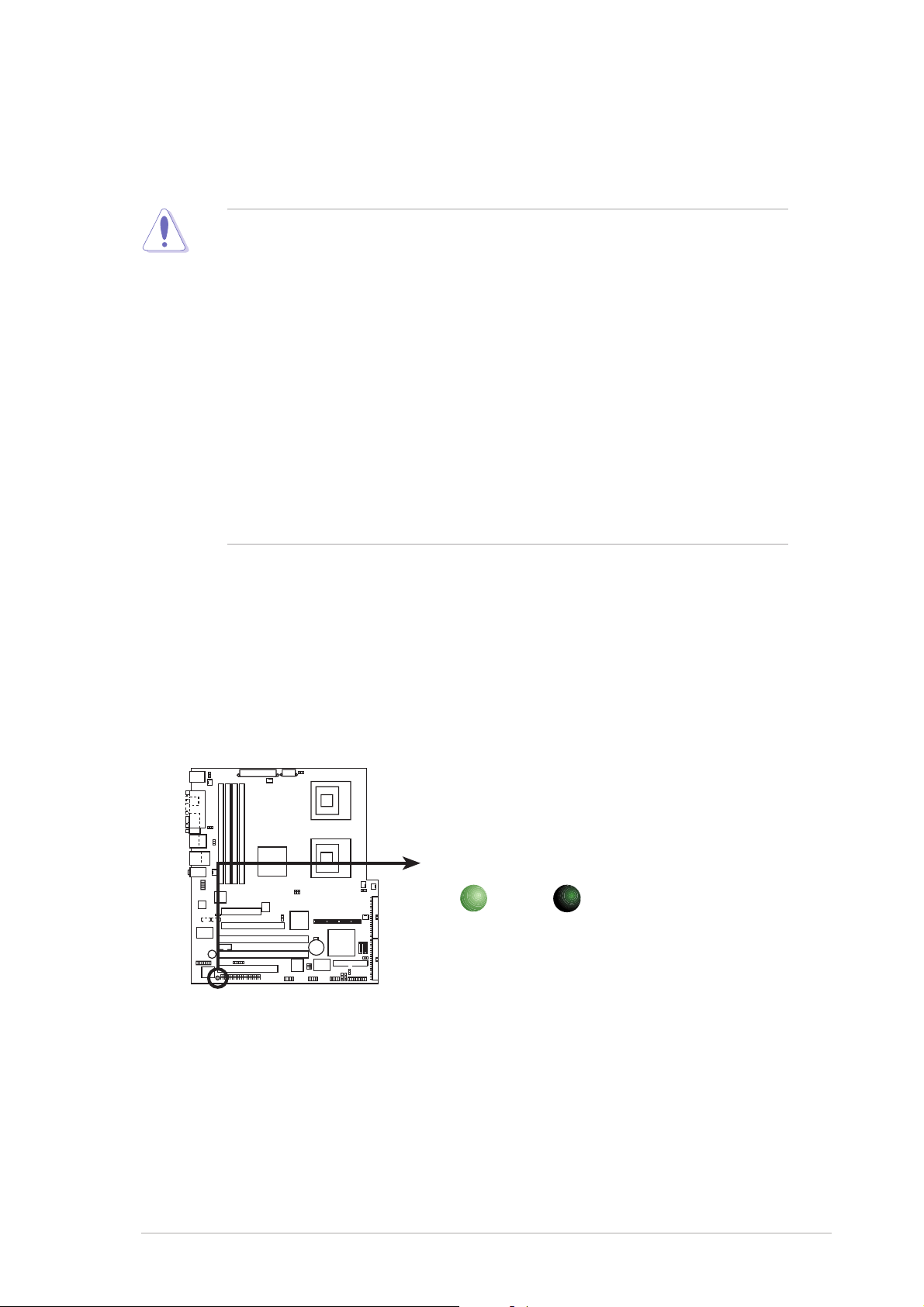
Onboard LEDOnboard LED
Onboard LED
Onboard LEDOnboard LED
The motherboard comes with a standby power LED. The green LED lights
up to indicate that the system is ON, in sleep mode, or in soft-off mode.
This is a reminder that you should shut down the system and unplug the
power cable before removing or plugging in any motherboard component.
The illustration below shows the location of the onboard LED.
SB_PWR1
ON
Standby
Power
NCT-D
NCT-D Standby power LED
OFF
Powere
Off
ASUS NCT-DASUS NCT-D
ASUS NCT-D
ASUS NCT-DASUS NCT-D
2-12-1
2-1
2-12-1
Page 24
2.2 Motherboard overview
Before you install the motherboard, study the configuration of your chassis
to ensure that the motherboard fits into it.
Make sure to unplug the chassis power cord before installing or removing
the motherboard. Failure to do so can cause you physical injury and
damage motherboard components.
2.2.12.2.1
2.2.1
2.2.12.2.1
When installing the motherboard, make sure that you place it into the
chassis in the correct orientation. The edge with external ports goes to the
rear part of the chassis as indicated in the image below.
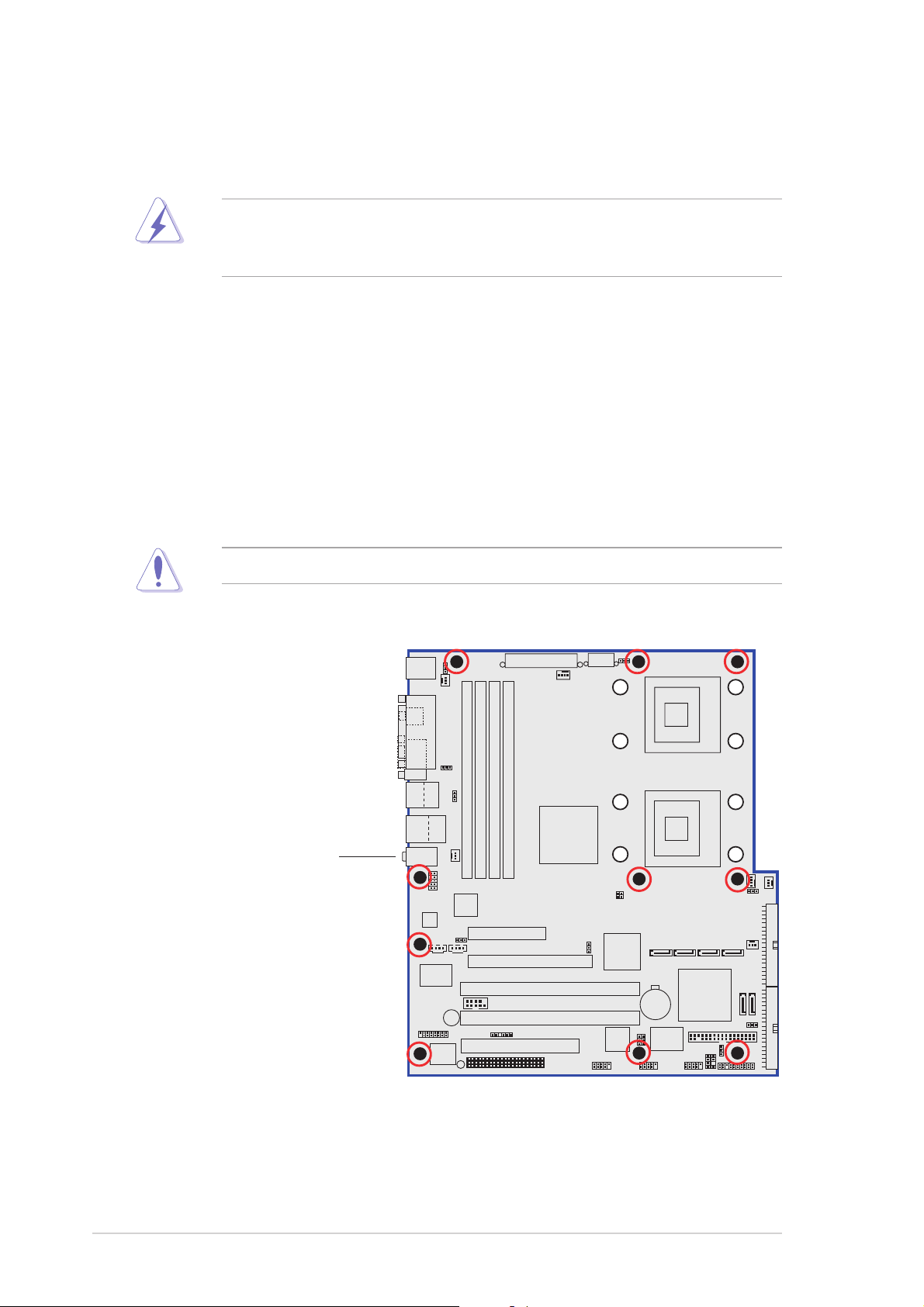
2.2.22.2.2
2.2.2
2.2.22.2.2
Place ten (10) screws into the holes indicated by circles to secure the
motherboard to the chassis.
Placement directionPlacement direction
Placement direction
Placement directionPlacement direction
Screw holesScrew holes
Screw holes
Screw holesScrew holes
Do not overtighten the screws! Doing so can damage the motherboard.
Place this side towardsPlace this side towards
Place this side towards
Place this side towardsPlace this side towards
the rear of the chassisthe rear of the chassis
the rear of the chassis
the rear of the chassisthe rear of the chassis
2-22-2
2-2
2-22-2
NCT-D
Chapter 2: Hardware informationChapter 2: Hardware information
Chapter 2: Hardware information
Chapter 2: Hardware informationChapter 2: Hardware information
Page 25
2.2.32.2.3
2.2.3
2.2.32.2.3
Support plates for motherboardSupport plates for motherboard
Support plates for motherboard
Support plates for motherboardSupport plates for motherboard
For additional protection from motherboard breakage due to the weight of
the CPU heatsinks, your motherboard package comes with a solution kit
that consists of:
• 2 x metal support plates
• 1 x contour sheet
• 3 different sets of metal nuts and rubber pads for varied chassis
standoffs (each set contains 8 metal nuts and 2 rubber pads)
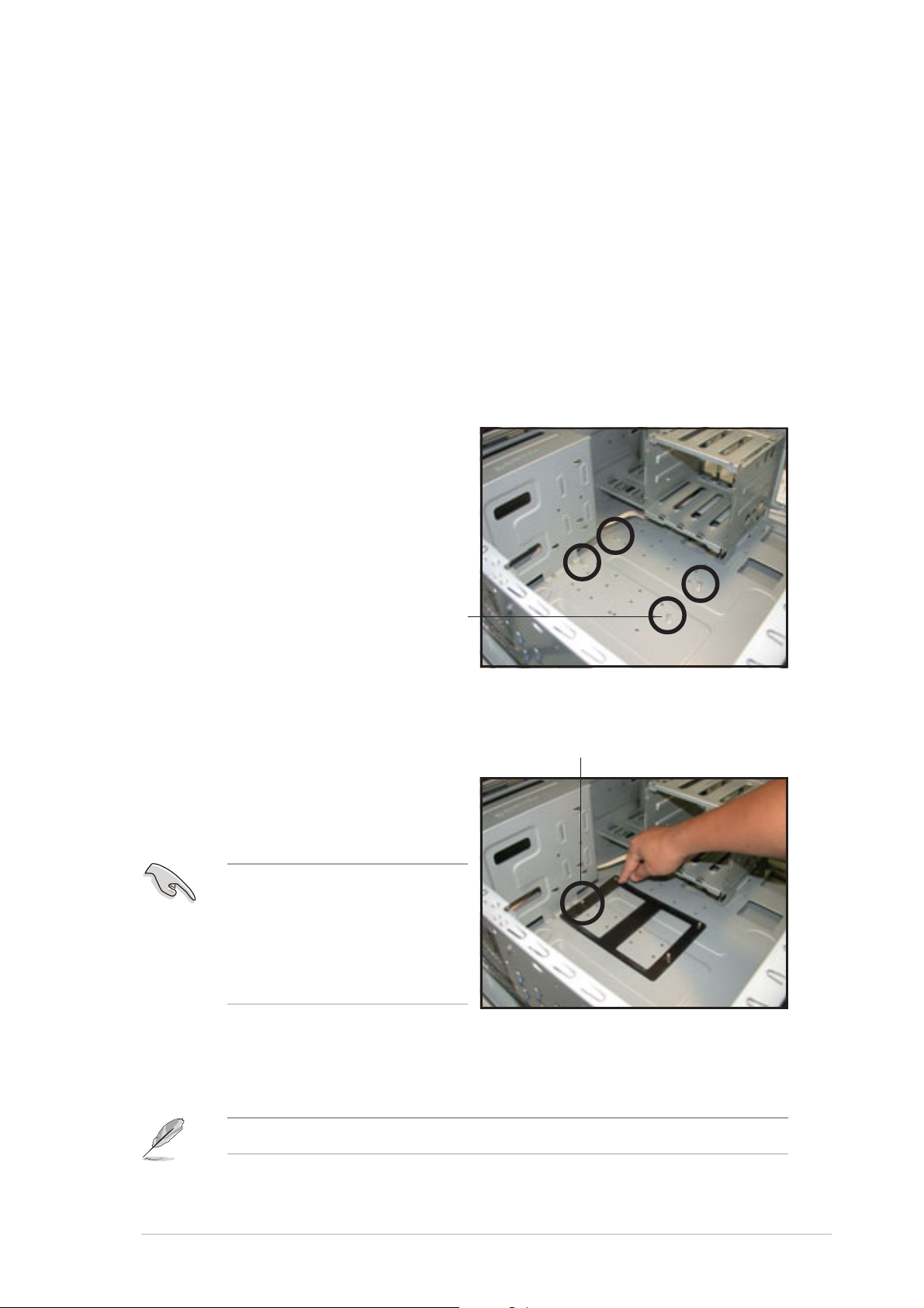
To install the support plates:
1. Open and lay your system
chassis flat on a stable surface,
then locate the motherboard
standoffs as shown.
StandoffStandoff
Standoff
StandoffStandoff
2. Align the holes of the contour
sheet with the standoffs on the
Standoff besideStandoff beside
Standoff beside
Standoff besideStandoff beside
power supply cagepower supply cage
power supply cage
power supply cagepower supply cage
base of the chassis. Press the
sheet flat making sure that it is
completely affixed to the
chassis.
The contour sheet fits in only
one orientation. Make sure
that the hole located about
1 cm from the corner
matches the standoff beside
the power supply cage.
3. Determine the height of the standoffs on your chassis, and select the
appropriate set of metal nuts and rubber pads from your package.
Use a nut size that is slightly lower than the standoffs on your chassis.
ASUS NCT-DASUS NCT-D
ASUS NCT-D
ASUS NCT-DASUS NCT-D
2-32-3
2-3
2-32-3
Page 26
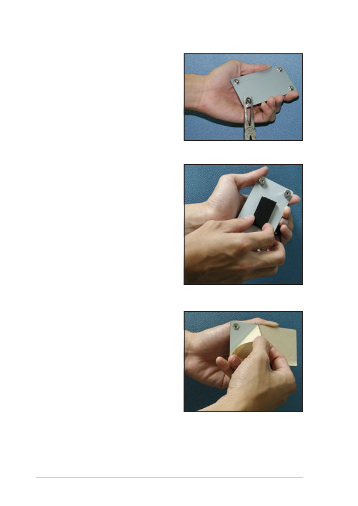
4. Use a plier to attach four nuts to
the bolts on the metal support
plate.
5. Align a rubber pad to the
rectagular mark on the center of
the plate, then press to attach.
6. Remove the adhesive label
underneath a plate.
2-42-4
2-4
2-42-4
Chapter 2: Hardware informationChapter 2: Hardware information
Chapter 2: Hardware information
Chapter 2: Hardware informationChapter 2: Hardware information
Page 27
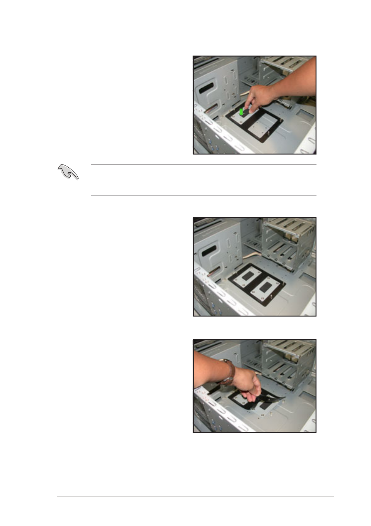
7. Carefully align and place the
plate on a rectangular cut on the
contour sheet.
Make sure that the metal support plates fit perfectly to the rectangular
cuts on the contour sheet; otherwise, the CPU heatsink screws would
not align to the metal nuts.
8. Repeat steps 4 and 7 to prepare
and install the second plate.
9. Remove the contour sheet from
the chassis.
ASUS NCT-DASUS NCT-D
ASUS NCT-D
ASUS NCT-DASUS NCT-D
2-52-5
2-5
2-52-5
Page 28
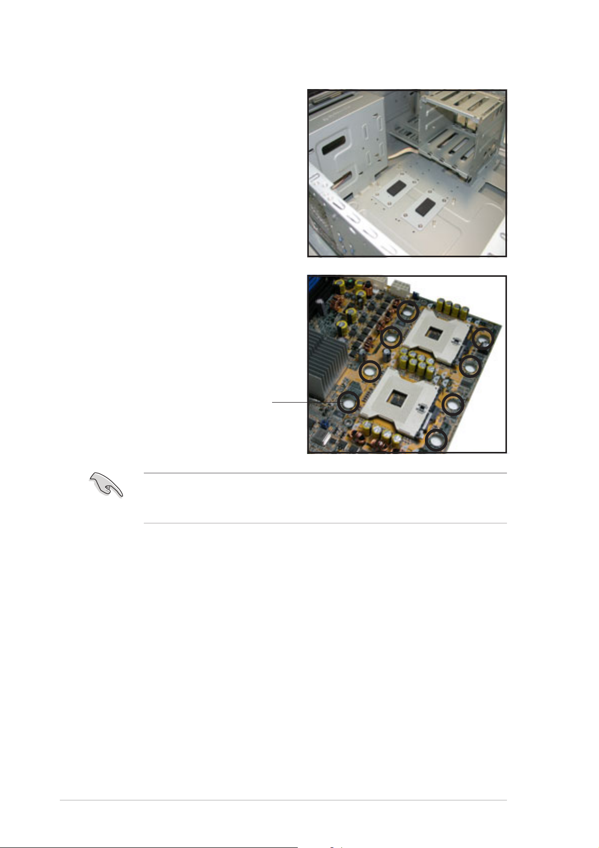
The support plates appear as
shown when installed.
10. Install the motherboard with the
external I/O ports toward the
chassis rear panel. The CPU
sockets should be right on top
of the support plates.
Heatsink hole matched toHeatsink hole matched to
Heatsink hole matched to
Heatsink hole matched toHeatsink hole matched to
a nut on the support platea nut on the support plate
a nut on the support plate
a nut on the support platea nut on the support plate
Make sure that the CPU heatsink holes on the motherboard perfectly
match the metal nuts on the support plates; otherwise, you can not
install the CPU heatsinks properly.
11. Secure the motherboard with 10 screws. Refer to section
“2.2.2 Screw holes” for illustration.
2-62-6
2-6
2-62-6
Chapter 2: Hardware informationChapter 2: Hardware information
Chapter 2: Hardware information
Chapter 2: Hardware informationChapter 2: Hardware information
Page 29
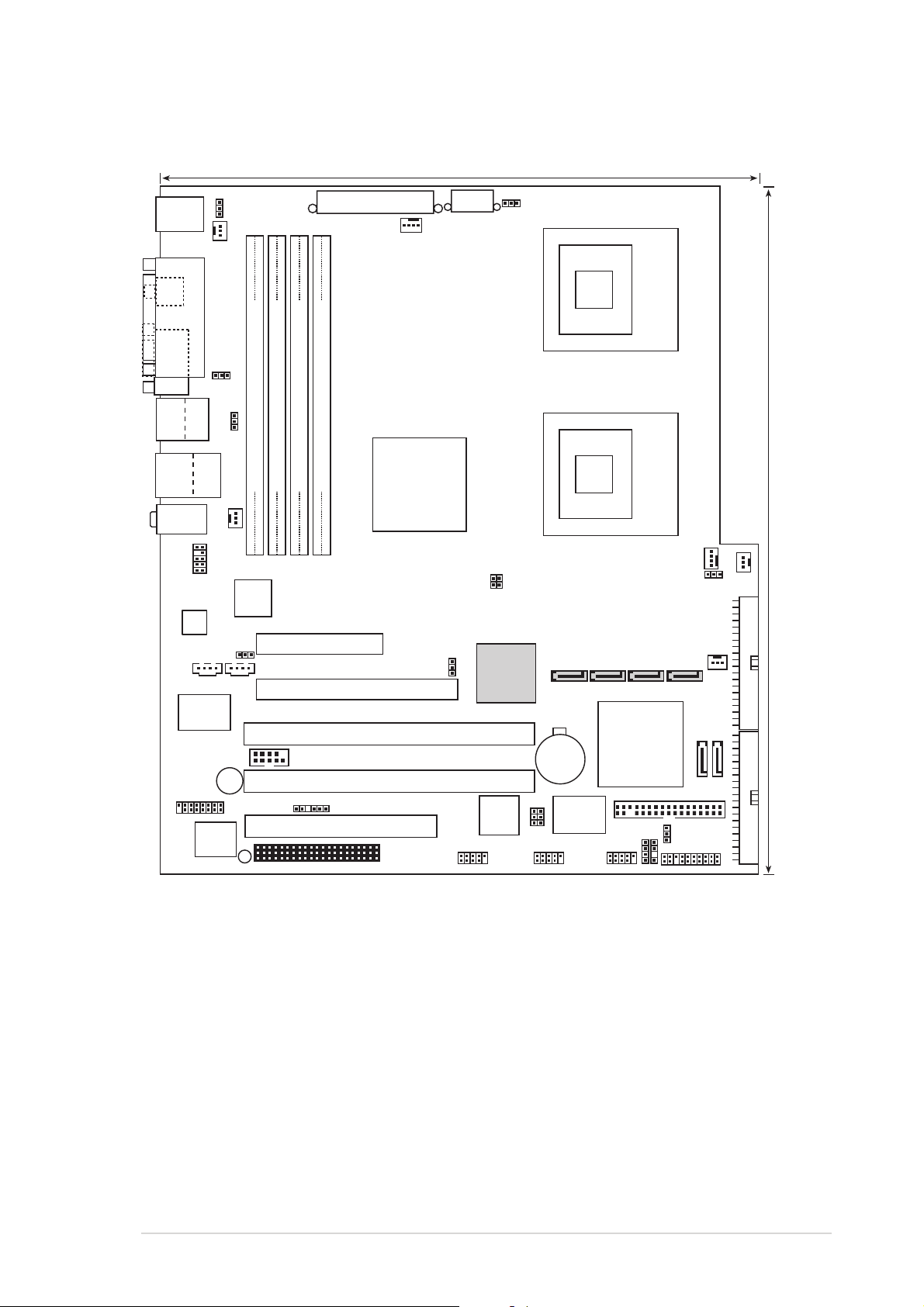
2.2.42.2.4
25cm (9.8in)
2.2.4
2.2.42.2.4
Motherboard layoutMotherboard layout
Motherboard layout
Motherboard layoutMotherboard layout
PS/2KBMS
T: Mouse
B: Keyboard
SPDIF
COM1
Bottom:
Top:
T:USB4
1394
B:USB3
USB2.0
T: USB1
B: USB2
Top:Line In
Center:Line Out
Below:Mic In
FP_AUDIO1
AD1980
BUZZER1
GAME1
REAR_FAN1
PARALLEL PORT
USBPW12
Top:
RJ-45
LAN_EN1
CD1
SUPER
I/O
AMI
BIOS
8Mb
KBPWR1
USBPW34
DDR DIMM_B2 (72 bit, 184-pin module)
DDR DIMM_A2 (72 bit, 184-pin module)
REAR_FAN2
Broadcom
BCM5751
ATXPWR1
DDR DIMM_B1 (72 bit, 184-pin module)
DDR DIMM_A1 (72 bit, 184-pin module)
PCIE1 (x4 link)
AUX1
PCIE2 (x16 link)
PCIX3 (64-bit PCI-X)
COM2
PCIX4 (64-bit PCI-X)
BPSMB1
PCI5 (32-bit 5V PCI)
SB_PWR1
NCT-D
CPU_FAN1
E7525
WIFI
Intel
MCH
SATA_EN1
ATX12V1
J4
J3
Adaptec
AIC-8130
TI
TSB43AB22A
FM_CPU1
CMOS Power
1394_EN1
SATA_RAID1
CR2032 3V
Lithium Cell
VT6212L
USB_EN1
VIA
CPU1
CPU2
SATA_RAID2
SATA_RAID3
Intel
6300ESB
ICH
FLOPPY
CHASSIS1
HDLED1
USB56USB78IE1394_2
mPGA 604
mPGA 604
CPU_FAN2
FM_CPU2
FRNT_FAN2
SATA_RAID4
CLRTC1
SEC_IDE
SATA1
PANEL1
FRNT_FAN1
30.5cm (12in)
SATA2
PRI_IDE
ASUS NCT-DASUS NCT-D
ASUS NCT-D
ASUS NCT-DASUS NCT-D
2-72-7
2-7
2-72-7
Page 30
2.2.52.2.5
2.2.5
2.2.52.2.5
Layout contentsLayout contents
Layout contents
Layout contentsLayout contents
SlotsSlots
Slots
SlotsSlots
PagePage
Page
PagePage
1. CPU sockets 2-10
2. DDR2 DIMM sockets 2-14
3. PCI/PCI-X/PCI Express slots 2-18
4. Wi-Fi slot 2-18
JumpersJumpers
Jumpers
JumpersJumpers
PagePage
Page
PagePage
1. Clear RTC RAM (CLRTC1) 2-19
2. CPU fan pin selection (3-pin FM_CPU1, FM_CPU2) 2-20
3. USB device wake-up (3-pin USBPW12, USBPW34) 2-20
5. Keyboard power (3-pin KBPWR1) 2-21
6. IEEE 1394 controller setting (3-pin 1394_EN1) 2-21
7. Gigabit LAN controller setting (3-pin LAN_EN1) 2-22
8. SATA controller setting (3-pin SATA_EN1) 2-22
9. USB controller setting (3-pin USB_EN1) 2-23
Rear panel connectorsRear panel connectors
Rear panel connectors
Rear panel connectorsRear panel connectors
PagePage
Page
PagePage
1. PS/2 mouse port (green) 2-24
2. Parallel port 2-24
3. IEEE 1394a port 2-24
4. LAN (RJ-45) port 2-24
5. Line In port (light blue) 2-24
6. Line Out port (lime) 2-24
7. Microphone port (pink) 2-24
8. USB 2.0 ports 3 and 4 2-25
9. USB 2.0 ports 1 and 2 2-25
10. Serial (COM1) port 2-25
11. Coaxial S/PDIF Out port 2-25
12. PS/2 keyboard port (purple) 2-25
2-82-8
2-8
2-82-8
Chapter 2: Hardware informationChapter 2: Hardware information
Chapter 2: Hardware information
Chapter 2: Hardware informationChapter 2: Hardware information
Page 31

Internal connectorsInternal connectors
Internal connectors
Internal connectorsInternal connectors
PagePage
Page
PagePage
1. Floppy disk drive connector (34-1 pin FLOPPY) 2-26
2. Primary IDE connector (40-1 pin PRI_IDE, SEC_IDE) 2-26
3. Serial ATA connectors (7-pin SATA1, SATA2) 2-27
4. Serial ATA RAID connectors (7-pin SATA_RAID1, SATA_RAID2,
SATA_RAID3, SATA_RAID4) 2-28
5. Hard disk activity LED connector (2-pin HDLED1) 2-28
6. Internal audio connectors (4-pin CD1, AUX1) 2-29
7. Chassis intrusion connector (4-1 pin CHASSIS1) 2-29
8. Front panel audio connector (10-1 pin FP_AUDIO1) 2-30
9. CPU, Chassis, and Power Fan connectors (3-pin CPU_FAN1/2,
REAR_FAN1/2, FRNT_FAN1/2) 2-30
10. IEEE 1394a port connector (10-1 pin IE1394_2) 2-31
11. USB connectors (10-1 pin USB56, USB78) 2-31
12. SSI power connectors (24-pin EATXPWR1, 8-pin ATX12V1) 2-32
13. Serial port connector (10-1 pin COM2) 2-33
14. GAME/MIDI port connector (16-1 pin GAME1) 2-33
15. Backplane SMBus connector (6-1 pin BPSMB1) 2-34
16. System panel connector (20-pin PANEL1) 2-34
System power LED (Green 3-pin PLED) 2-34
Hard disk drive activity LED (Red 2-pin IDE_LED) 2-35
System warning speaker (Orange 4-pin SPEAKER) 2-35
ATX power button/soft-off button (Yellow 2-pin PWRSW) 2-35
Reset button (Blue 2-pin RESET) 2-35
ASUS NCT-DASUS NCT-D
ASUS NCT-D
ASUS NCT-DASUS NCT-D
2-92-9
2-9
2-92-9
Page 32

2.3 Central Processing Unit (CPU)
The motherboard comes with surface mount 604-pin Zero Insertion Force
(ZIF) sockets. The sockets are designed for the Intel
the 604-pin package with 1 MB L2 cache. The new generation Intel
processor supports 800 MHz system bus and Extended Memory 64-bit
Technology (EM64T).
®
Xeon™ processor in
®
Xeon™
2.3.12.3.1
2.3.1
2.3.12.3.1
Installling the CPUInstallling the CPU
Installling the CPU
Installling the CPUInstallling the CPU
To install a CPU:
1. Locate the CPU sockets on the motherboard.
Intel Xeon
Gold Arrow
NCT-D
NCT-D Socket 604
If installing only one CPU, use the socket CPU1.
2. Flip up the socket lever and push
it all the way to the other side.
Make sure that the socket
lever is pushed back all the
way, otherwise the CPU does
not fit in completely.
Socket for CPU1
2-102-10
2-10
2-102-10
Chapter 2: Hardware informationChapter 2: Hardware information
Chapter 2: Hardware information
Chapter 2: Hardware informationChapter 2: Hardware information
Page 33

3. Position the CPU above the
socket as shown.
4. Carefully insert the CPU into the
socket until it fits in place.
The CPU fits only in one
correct orientation. DO NOT
force the CPU into the socket
to prevent bending the pins
and damaging the CPU!
5. Carefully push down the socket
lever to secure the CPU. The
lever clicks on the side tab to
indicate that it is locked.
6. Apply the thermal interface
material (thermal grease) to the
top of the CPU. This thermal
grease should come with the CPU
package.
Marked cornerMarked corner
Marked corner
Marked cornerMarked corner
(gold arrow)(gold arrow)
(gold arrow)
(gold arrow)(gold arrow)
7. Repeat steps 1 to 6 if you wish
to install a second CPU.
ASUS NCT-DASUS NCT-D
ASUS NCT-D
ASUS NCT-DASUS NCT-D
2-112-11
2-11
2-112-11
Page 34

2.3.22.3.2
2.3.2
2.3.22.3.2
Installing the CPU heatsink and fanInstalling the CPU heatsink and fan
Installing the CPU heatsink and fan
Installing the CPU heatsink and fanInstalling the CPU heatsink and fan
The Intel® Xeon™ processors require an Intel® certified heatsink and fan
assembly to ensure optimum thermal condition and performance.
®
When you buy a boxed Intel
CPU, the package includes the heatsink, fan,
retention brackets, screws, thermal grease, installation manual, and other
items that are necessary for CPU installation.
•
Make sure that you have applied the thermal grease to the top of
the CPU before installing the heatsink and fan.
•
Refer to the installation manual that came with the CPU package for
details on heatsink/fan assembly and installation.
CPU heatsink (top view)CPU heatsink (top view)
CPU heatsink (top view)
CPU heatsink (top view)CPU heatsink (top view)
CPU heatsink (bottom view)CPU heatsink (bottom view)
CPU heatsink (bottom view)
CPU heatsink (bottom view)CPU heatsink (bottom view)
Before installing the CPU heatsinks, ensure that the jumpers FM_CPU1
and FM_CPU2 are set correctly depending on the pin definition of your
CPU fan cables. Refer to page 2-19 for information on these jumpers.
To install the CPU heatsink and fan:
1. Place the heatsink on top of the
installed CPU, making sure that
the four screws on the heatsink
align with the nuts on the
support plate.
Heatsink screw
2-122-12
2-12
2-122-12
Chapter 2: Hardware informationChapter 2: Hardware information
Chapter 2: Hardware information
Chapter 2: Hardware informationChapter 2: Hardware information
Page 35

2. Use a Phillips screwdriver to
tighten the four heatsink screws
in a diagonal sequence.
3. Connect the fan cable to the
4-pin connector labeled
CPU_FAN1.
Do not forget to connect the
CPU fan connector! Hardware
monitoring errors may occur if
you fail to plug this connector.
4. Repeat steps 1 to 3 to install
the other heatsink if you have
installed a second CPU, then
connect the fan cable to the
4-pin connector labeled
CPU_FAN2.
The heatsinks appear as shown
when installed.
ASUS NCT-DASUS NCT-D
ASUS NCT-D
ASUS NCT-DASUS NCT-D
2-132-13
2-13
2-132-13
Page 36

2.4 System memory
2
1
1
2.4.12.4.1
2.4.1
2.4.12.4.1
OverviewOverview
Overview
OverviewOverview
The motherboard comes with four Double Data Rate 2 (DDR2) Dual Inline
Memory Modules (DIMM) sockets.
A DDR2 module has the same physical dimensions as a DDR DIMM but has a
240-pin footprint. DDR2 DIMMs are notched to match the break on the
socket and ensure correct installation.
The figure illustrates the location of the DDR2 DIMM sockets:
DIMM_A
NCT-D
NCT-D DDR2 DIMM sockets
DIMM_B
DIMM_A2DIMM_B
2.4.22.4.2
2.4.2
2.4.22.4.2
Memory configurationsMemory configurations
Memory configurations
Memory configurationsMemory configurations
You may install 256 MB, 512 MB and 1 GB registered ECC DDR2 DIMMs into
the DIMM sockets.
• Always install DIMMs with the same CAS latency. For optimum
compatibility, it is recommended that you obtain memory modules
from the same vendor. Refer to the DDR2 Qualified Vendors List on
the ASUS website (www.asus.com) for details.
• This motherboard does not support memory modules made up of
128 Mb chips or double sided x16 memory modules.
2-142-14
2-14
2-142-14
Chapter 2: Hardware informationChapter 2: Hardware information
Chapter 2: Hardware information
Chapter 2: Hardware informationChapter 2: Hardware information
Page 37

2.4.32.4.3
2.4.3
2.4.32.4.3
Installing a DIMMInstalling a DIMM
Installing a DIMM
Installing a DIMMInstalling a DIMM
Unplug the power supply before adding or removing DIMMs or other
system components. Failure to do so can cause severe damage to both
the motherboard and the components.
To install a DIMM:
1. Unlock a DIMM socket by
pressing the retaining clips
outward.
2. Align a DIMM on the socket
such that the notch on the
DIMM matches the break on
the socket.
3. Firmly insert the DIMM into
the socket until the retaining
clips snap back in place and
the DIMM is properly seated.
2
DDR2 DIMM notchDDR2 DIMM notch
DDR2 DIMM notch
3
1
Unlocked retaining clipUnlocked retaining clip
Unlocked retaining clip
Unlocked retaining clipUnlocked retaining clip
DDR2 DIMM notchDDR2 DIMM notch
• A DDR2 DIMM is keyed with a notch so that it fits in only one
direction. Do not force a DIMM into a socket to avoid damaging the
DIMM.
• The DDR2 DIMM sockets do not support DDR DIMMs. DO NOT install
DDR DIMMs to the DDR2 DIMM sockets.
2.4.42.4.4
2.4.4
2.4.42.4.4
Removing a DIMMRemoving a DIMM
Removing a DIMM
Removing a DIMMRemoving a DIMM
Follow these steps to remove a DIMM.
1. Simultaneously press the
retaining clips outward to unlock
the DIMM.
Support the DIMM lightly with
your fingers when pressing the
retaining clips. The DIMM
might get damaged when it
flips out with extra force.
2
1
DDR2 DIMM notchDDR2 DIMM notch
DDR2 DIMM notch
1
DDR2 DIMM notchDDR2 DIMM notch
2. Remove the DIMM from the socket.
ASUS NCT-DASUS NCT-D
ASUS NCT-D
ASUS NCT-DASUS NCT-D
2-152-15
2-15
2-152-15
Page 38

2.5 Expansion slots
In the future, you may need to install expansion cards. The following
sub-sections describe the slots and the expansion cards that they support.
Make sure to unplug the power cord before adding or removing
expansion cards. Failure to do so may cause you physical injury and
damage motherboard components.
2.5.12.5.1
2.5.1
2.5.12.5.1
To install an expansion card:
1. Before installing the expansion card, read the documentation that
came with it and make the necessary hardware settings for the card.
2. Remove the system unit cover (if your motherboard is already
installed in a chassis).
3. Remove the bracket opposite the slot that you intend to use. Keep
the screw for later use.
4. Align the card connector with the slot and press firmly until the card is
completely seated on the slot.
5. Secure the card to the chassis with the screw you removed earlier.
6. Replace the system cover.
2.5.22.5.2
2.5.2
2.5.22.5.2
After installing the expansion card, configure the it by adjusting the
software settings.
Installing an expansion cardInstalling an expansion card
Installing an expansion card
Installing an expansion cardInstalling an expansion card
Configuring an expansion cardConfiguring an expansion card
Configuring an expansion card
Configuring an expansion cardConfiguring an expansion card
1. Turn on the system and change the necessary BIOS settings, if any.
See Chapter 4 for information on BIOS setup.
2. Assign an IRQ to the card. Refer to the tables on the next page.
3. Install the software drivers for the expansion card.
When using PCI cards on shared slots, ensure that the drivers support
“Share IRQ” or that the cards do not need IRQ assignments. Otherwise,
conflicts will arise between the two PCI groups, making the system
unstable and the card inoperable.
2-162-16
2-16
2-162-16
Chapter 2: Hardware informationChapter 2: Hardware information
Chapter 2: Hardware information
Chapter 2: Hardware informationChapter 2: Hardware information
Page 39

2.5.32.5.3
2.5.3
2.5.32.5.3
Standard interrupt assignmentsStandard interrupt assignments
Standard interrupt assignments
Standard interrupt assignmentsStandard interrupt assignments
Interrupt assignmentsInterrupt assignments
Interrupt assignments
Interrupt assignmentsInterrupt assignments
IRQIRQ
IRQ
IRQIRQ
0 1 System Timer
1 2 Keyboard Controller
2 — Re-direct to IRQ#9
3 11 Communications Port (COM2)*
4 12 Communications Port (COM1)*
5 13 IRQ holder for PCI steering*
6 14 Floppy Disk Controller
7 15 Printer Port (LPT1)*
8 3 System CMOS/Real Time Clock
9 4 IRQ holder for PCI steering*
10 5 IRQ holder for PCI steering*
11 6 IRQ holder for PCI steering*
12 7 PS/2 Compatible Mouse Port*
13 8 Numeric Data Processor
14 9 Primary IDE Channel
15 10 Secondary IDE Channel
PriorityPriority
Priority
PriorityPriority
Standard FunctionStandard Function
Standard Function
Standard FunctionStandard Function
* These IRQs are usually available for ISA or PCI devices.
ASUS NCT-DASUS NCT-D
ASUS NCT-D
ASUS NCT-DASUS NCT-D
2-172-17
2-17
2-172-17
Page 40

2.5.42.5.4
2.5.4
2.5.42.5.4
The PCI/PCI-X slots support cards
such as a LAN card, SCSI card, USB
card, and other cards that comply
with PCI 2.3 and PCI-X 1.0a
specifications. The figure shows a
LAN card installed on a PCI slot.
PCI/PCI-X slotsPCI/PCI-X slots
PCI/PCI-X slots
PCI/PCI-X slotsPCI/PCI-X slots
2.5.52.5.5
2.5.5
2.5.52.5.5
This motherboard supports PCI
Express™ x16 graphic cards that
comply with the PCI Express™
specifications. The following figure
shows a graphics card installed on
the PCI Express™ x16 slot.
The onboard PCI Express™ x8 slot
provides x4 link to the MCH. This slot
is designed for various server class
high performance add-on cards like
SCSI RAID card, fiber-channel card,
etc.
2.5.62.5.6
2.5.6
2.5.62.5.6
The Wi-Fi (Wireless Fidelity) slot supports the ASUS WiFi-b module. Visit
the ASUS website (www.asus.com) for product details.
The Wi-Fi slot conforms to the Institute of Electrical and Electronics
Engineers (IEEE) 802.11b standard for wireless devices operating in the
2.4 GHz frequency band.
PCI Express™ x8/x16 slotsPCI Express™ x8/x16 slots
PCI Express™ x8/x16 slots
PCI Express™ x8/x16 slotsPCI Express™ x8/x16 slots
Wi-Fi slotWi-Fi slot
Wi-Fi slot
Wi-Fi slotWi-Fi slot
2-182-18
2-18
2-182-18
WIFI1
NCT-D
NCT-D Wireless module connector
Chapter 2: Hardware informationChapter 2: Hardware information
Chapter 2: Hardware information
Chapter 2: Hardware informationChapter 2: Hardware information
Page 41

2.6 Jumpers
S
1.1.
Clear RTC RAM (CLRTC1)Clear RTC RAM (CLRTC1)
1.
Clear RTC RAM (CLRTC1)
1.1.
Clear RTC RAM (CLRTC1)Clear RTC RAM (CLRTC1)
This jumper allows you to clear the Real Time Clock (RTC) RAM in
CMOS. You can clear the CMOS memory of date, time, and system
setup parameters by erasing the CMOS RTC RAM data. The onboard
button cell battery powers the RAM data in CMOS, which include
system setup information such as system passwords.
To erase the RTC RAM:
1. Turn OFF the computer and unplug the power cord.
2. Remove the onboard battery.
3. Move the jumper cap from pins 1-2 (default) to pins 2-3. Keep the
cap on pins 2-3 for about 5~10 seconds, then move the cap back
to pins 1-2.
4. Re-install the battery.
5. Plug the power cord and turn ON the computer.
6. Hold down the <Del> key during the boot process and enter BIOS
setup to re-enter data.
Except when clearing the RTC RAM, never remove the cap on CLRTC
jumper default position. Removing the cap will cause system boot failure!
CLRTC1
3
22
NCT-D
NCT-D Clear RTC RAM
You do not need to clear the RTC when the system hangs due to
overclocking. For system failure due to overclocking, use the C.P.R. (CPU
Parameter Recall) feature. Shut down and reboot the system so the BIOS
can automatically reset parameter settings to default values.
1
Normal
(Default)
Clear CMO
ASUS NCT-DASUS NCT-D
ASUS NCT-D
ASUS NCT-DASUS NCT-D
2-192-19
2-19
2-192-19
Page 42

2.2.
t)
t)
CPU fan pin selection (3-pin FM_CPU1, FM_CPU2)CPU fan pin selection (3-pin FM_CPU1, FM_CPU2)
2.
CPU fan pin selection (3-pin FM_CPU1, FM_CPU2)
2.2.
CPU fan pin selection (3-pin FM_CPU1, FM_CPU2)CPU fan pin selection (3-pin FM_CPU1, FM_CPU2)
These jumpers allow you to connect either a 3-pin or a 4-pin fan cable
plug to the CPU fan connectors (CPU_FAN1, CPU_FAN2). Set these
jumpers to pins 1-2 if you are using a 3-pin fan cable plug, or to pins
2-3 if you are using a 4-pin plug.
FM_CPU1
NCT-D
NCT-D FM_CPU Setting
12
DC mode PWM
(Default)
FM_CPU2
12
DC mode PWM
(Default)
23
23
3.3.
USB device wake-up (3-pin USBPW12, USBPW34)USB device wake-up (3-pin USBPW12, USBPW34)
3.
USB device wake-up (3-pin USBPW12, USBPW34)
3.3.
USB device wake-up (3-pin USBPW12, USBPW34)USB device wake-up (3-pin USBPW12, USBPW34)
Set these jumpers to +5V to wake up the computer from S1 sleep
mode (CPU stopped, DRAM refreshed, system running in low power
mode) using the connected USB devices. Set to +5VSB to wake up
from S3 and S4 sleep modes (no power to CPU, DRAM in slow refresh,
power supply in reduced power mode).
USBPW12
2312
NCT-D
NCT-D USB device wake up
Enable Disable
USBPW34
22
1
Enable Disable
(Defaul
3
(Defaul
2-202-20
2-20
2-202-20
• The USB device wake-up feature requires a power supply that can
provide 500mA on the +5VSB lead for each USB port; otherwise, the
system would not power up.
• The total current consumed must NOT exceed the power supply
capability (+5VSB) whether under normal condition or in sleep mode.
Chapter 2: Hardware informationChapter 2: Hardware information
Chapter 2: Hardware information
Chapter 2: Hardware informationChapter 2: Hardware information
Page 43

4.4.
e
e
Keyboard power (3-pin KBPWR1)Keyboard power (3-pin KBPWR1)
4.
Keyboard power (3-pin KBPWR1)
4.4.
Keyboard power (3-pin KBPWR1)Keyboard power (3-pin KBPWR1)
This jumper allows you to enable or disable the keyboard wake-up
feature. Set this jumper to pins 2-3 (+5VSB) to wake up the computer
when you press a key on the keyboard (the default is the Space Bar).
This feature requires an ATX power supply that can supply at least 1A
on the +5VSB lead, and a corresponding setting in the BIOS.
KBPWR1
3
22
1
Enable
(Default)
NCT-D
NCT-D Keyboard power setting
Disabl
5.5.
IEEE 1394 controller setting (3-pin 1394_EN1)IEEE 1394 controller setting (3-pin 1394_EN1)
5.
IEEE 1394 controller setting (3-pin 1394_EN1)
5.5.
IEEE 1394 controller setting (3-pin 1394_EN1)IEEE 1394 controller setting (3-pin 1394_EN1)
These jumpers allow you to enable or disable the onboard TI
TBS43AB22A PCI IEEE 1394a controller. Set to pins 1-2 to activate
the 1394 feature.
1394_EN1
3
22
1
NCT-D
NCT-D 1394 Function setting
Enable
(Default)
Disabl
ASUS NCT-DASUS NCT-D
ASUS NCT-D
ASUS NCT-DASUS NCT-D
2-212-21
2-21
2-212-21
Page 44

6.6.
e
e
Gigabit LAN controller setting (3-pin LAN_EN1)Gigabit LAN controller setting (3-pin LAN_EN1)
6.
Gigabit LAN controller setting (3-pin LAN_EN1)
6.6.
Gigabit LAN controller setting (3-pin LAN_EN1)Gigabit LAN controller setting (3-pin LAN_EN1)
These jumpers allow you to enable or disable the onboard Broadcom
BCM5751 Gigabit LAN controller. Set to pins 1-2 to activate the
Gigabit LAN feature.
LAN_EN1
21 32
NCT-D
Enable
(Default)
Disabl
NCT-D LAN_EN setting
7.7.
SATA controller setting (3-pin SATA_EN1)SATA controller setting (3-pin SATA_EN1)
7.
SATA controller setting (3-pin SATA_EN1)
7.7.
SATA controller setting (3-pin SATA_EN1)SATA controller setting (3-pin SATA_EN1)
These jumpers allow you to enable or disable the onboard Adaptec
AIC-8130 SATA RAID controller. Set to pins 1-2 to activate the SATA
RAID feature.
SATA_EN1
3
22
1
NCT-D
NCT-D SATA_EN setting
Enable
(Default)
Disabl
2-222-22
2-22
2-222-22
Chapter 2: Hardware informationChapter 2: Hardware information
Chapter 2: Hardware information
Chapter 2: Hardware informationChapter 2: Hardware information
Page 45

8.8.
e
USB controller setting (3-pin USB_EN1)USB controller setting (3-pin USB_EN1)
8.
USB controller setting (3-pin USB_EN1)
8.8.
USB controller setting (3-pin USB_EN1)USB controller setting (3-pin USB_EN1)
These jumpers allow you to enable or disable the onboard VIA
VT6212 PCI USB 2.0 controller. Set to pins 1-2 to activate the USB
feature.
USB_EN1
3
22
1
NCT-D
NCT-D USB setting
Enable
(Default)
Disabl
ASUS NCT-DASUS NCT-D
ASUS NCT-D
ASUS NCT-DASUS NCT-D
2-232-23
2-23
2-232-23
Page 46

2.7 Connectors
12
4
3
2.7.12.7.1
2.7.1
2.7.12.7.1
12
1.1.
PS/2 mouse port (green).PS/2 mouse port (green).
1.
PS/2 mouse port (green). This port is for a PS/2 mouse.
1.1.
PS/2 mouse port (green).PS/2 mouse port (green).
2.2.
Parallel port.Parallel port.
2.
Parallel port. This 25-pin port connects a parallel printer, a scanner,
2.2.
Parallel port.Parallel port.
Rear panel connectorsRear panel connectors
Rear panel connectors
Rear panel connectorsRear panel connectors
911 10
8
or other devices.
3.3.
IEEE 1394a port.IEEE 1394a port.
3.
IEEE 1394a port. This 6-pin IEEE 1394a port provides high-speed
3.3.
IEEE 1394a port.IEEE 1394a port.
connectivity for audio/video devices, storage peripherals, PCs, or
portable devices.
5
6
7
4.4.
LAN (RJ-45) port.LAN (RJ-45) port.
4.
LAN (RJ-45) port. This port allows Gigabit connection to a Local
4.4.
LAN (RJ-45) port.LAN (RJ-45) port.
Area Network (LAN) through a network hub. Refer to the table below
for the LAN port LED indications.
LAN port LED indicationsLAN port LED indications
LAN port LED indications
LAN port LED indicationsLAN port LED indications
ACT/LINK LEDACT/LINK LED
ACT/LINK LED
ACT/LINK LEDACT/LINK LED
StatusStatus
Status
StatusStatus
OFF No link OFF 10 Mbps connection
GREEN Linked ORANGE 100 Mbps connection
BLINKING Data activity GREEN 1 Gbps connection
5.5.
Line In port (light blue).Line In port (light blue).
5.
Line In port (light blue). This port connects a tape, CD, DVD
5.5.
Line In port (light blue).Line In port (light blue).
DescriptionDescription
Description
DescriptionDescription
StatusStatus
Status
StatusStatus
player, or other audio sources.
6.6.
Line Out port (lime).Line Out port (lime).
6.
Line Out port (lime). This port connects a headphone or a
6.6.
Line Out port (lime).Line Out port (lime).
speaker. In 4-channel, 6-channel, and 8-channel configuration, the
function of this port becomes Front Speaker Out.
7.7.
Microphone port (pink). Microphone port (pink).
7.
Microphone port (pink). This port connects a microphone.
7.7.
Microphone port (pink). Microphone port (pink).
ACT/LINKACT/LINK
ACT/LINK
SPEED LEDSPEED LED
SPEED LED
SPEED LEDSPEED LED
Description0Description0
Description0
Description0Description0
ACT/LINKACT/LINK
LEDLED
LED
LEDLED
LAN portLAN port
LAN port
LAN portLAN port
SPEEDSPEED
SPEED
SPEEDSPEED
LEDLED
LED
LEDLED
2-242-24
2-24
2-242-24
Refer to the audio configuration table on the next page for the function
of the audio ports in 2/4/6-channel configurations.
Chapter 2: Hardware informationChapter 2: Hardware information
Chapter 2: Hardware information
Chapter 2: Hardware informationChapter 2: Hardware information
Page 47

Audio 2/4/6-channel configurationsAudio 2/4/6-channel configurations
Audio 2/4/6-channel configurations
Audio 2/4/6-channel configurationsAudio 2/4/6-channel configurations
PortPort
Port
PortPort
Light BlueLight Blue
Light Blue Line In Line In Bass/Center
Light BlueLight Blue
LimeLime
Lime Line Out Front Speaker Out Front Speaker Out
LimeLime
PinkPink
Pink Mic In Rear Speaker Out Rear Speaker Out
PinkPink
8.8.
USB 2.0 ports 3 and 4.USB 2.0 ports 3 and 4.
8.
USB 2.0 ports 3 and 4. These two 4-pin Universal Serial Bus
8.8.
USB 2.0 ports 3 and 4.USB 2.0 ports 3 and 4.
2-channel2-channel
2-channel
2-channel2-channel
(Headset)(Headset)
(Headset)
(Headset)(Headset)
4-channel4-channel
4-channel
4-channel4-channel
6-channel6-channel
6-channel
6-channel6-channel
(USB) ports are available for connecting USB 2.0 devices.
9.9.
USB 2.0 ports 1 and 2.USB 2.0 ports 1 and 2.
9.
USB 2.0 ports 1 and 2. These two 4-pin Universal Serial Bus
9.9.
USB 2.0 ports 1 and 2.USB 2.0 ports 1 and 2.
(USB) ports are available for connecting USB 2.0 devices.
10.10.
Serial (COM1) portSerial (COM1) port
10.
Serial (COM1) port. This 9-pin communication port is for pointing
10.10.
Serial (COM1) portSerial (COM1) port
devices or other serial devices.
11.11.
Coaxial S/PDIF Out port.Coaxial S/PDIF Out port.
11.
Coaxial S/PDIF Out port. This port connects an external audio
11.11.
Coaxial S/PDIF Out port.Coaxial S/PDIF Out port.
output device via a coaxial S/PDIF cable.
12.12.
PS/2 keyboard port (purple).PS/2 keyboard port (purple).
12.
PS/2 keyboard port (purple). This port is for a PS/2 keyboard.
12.12.
PS/2 keyboard port (purple).PS/2 keyboard port (purple).
ASUS NCT-DASUS NCT-D
ASUS NCT-D
ASUS NCT-DASUS NCT-D
2-252-25
2-25
2-252-25
Page 48

2.7.22.7.2
n
2.7.2
2.7.22.7.2
1.1.
Floppy disk drive connector (34-1 pin FLOPPY)Floppy disk drive connector (34-1 pin FLOPPY)
1.
Floppy disk drive connector (34-1 pin FLOPPY)
1.1.
Floppy disk drive connector (34-1 pin FLOPPY)Floppy disk drive connector (34-1 pin FLOPPY)
Internal connectorsInternal connectors
Internal connectors
Internal connectorsInternal connectors
This connector is for the provided floppy disk drive (FDD) signal cable.
Insert one end of the cable to this connector, then connect the other
end to the signal connector at the back of the floppy disk drive.
Pin 5 on the connector is removed to prevent incorrect cable connection
when using a FDD cable with a covered Pin 5.
FLOPPY
PIN 1
NOTE: Orient the red markings o
the floppy ribbon cable to PIN 1.
NCT-D
NCT-D Floppy disk drive connector
2.2.
Primary IDE connector (40-1 pin PRI_IDE, SEC_IDE)Primary IDE connector (40-1 pin PRI_IDE, SEC_IDE)
2.
Primary IDE connector (40-1 pin PRI_IDE, SEC_IDE)
2.2.
Primary IDE connector (40-1 pin PRI_IDE, SEC_IDE)Primary IDE connector (40-1 pin PRI_IDE, SEC_IDE)
This connector is for an Ultra DMA 100/66 signal cable. The Ultra
DMA 100/66 signal cable has three connectors: a blue connector for
the primary IDE connector on the motherboard, a black connector for
an Ultra DMA 100/66 IDE slave device (optical drive/hard disk drive),
and a gray connector for an Ultra DMA 100/66 IDE master device (hard
disk drive). If you install two hard disk drives, you must configure the
second drive as a slave device by setting its jumper accordingly. Refer
to the hard disk documentation for the jumper settings.
• Pin 20 on the IDE connector is removed to match the covered hole
on the Ultra DMA cable connector. This prevents incorrect insertion
when you connect the IDE cable.
• Use the 80-conductor IDE cable for Ultra DMA 100/66 IDE devices.
PIN 1PIN 1
SEC_IDE
PRI_IDE
2-262-26
2-26
2-262-26
NCT-D
NCT-D IDE connectors
NOTE: Orient the red markings
(usually zigzag) on the IDE
ribbon cable to PIN 1.
Chapter 2: Hardware informationChapter 2: Hardware information
Chapter 2: Hardware information
Chapter 2: Hardware informationChapter 2: Hardware information
Page 49

3.3.
Serial ATA connectors (7-pin SATA1, SATA2)Serial ATA connectors (7-pin SATA1, SATA2)
3.
Serial ATA connectors (7-pin SATA1, SATA2)
3.3.
Serial ATA connectors (7-pin SATA1, SATA2)Serial ATA connectors (7-pin SATA1, SATA2)
These connectors are for the Serial ATA signal cables for Serial ATA
hard disk drives.
If you installed Serial ATA hard disk drives, you can create a RAID 0 or
®
RAID 1 configuration using the Adaptec
HostRAID™ technology
embedded in the Intel® 6300ESB chip.
These connectors are set to
SS
tandard IDE tandard IDE
S
tandard IDE mode, you can connect Serial ATA boot/data hard disk
SS
tandard IDE tandard IDE
Standard IDE Standard IDE
Standard IDE mode by default. In
Standard IDE Standard IDE
drives to these connectors. If you intend to create a Serial ATA RAID set
using these connectors, set the
Configure SATA As Configure SATA As
Configure SATA As item in the BIOS
Configure SATA As Configure SATA As
to [RAID]. See section “4.3.6 IDE Configuration” on page 4-16 for details.
GND
RSATA_TXP2
RSATA_TXN2
GND
RSATA_RXN2
RSATA_RXP2
GND
SATA2
NCT-D
GND
RSATA_TXP1
RSATA_TXN1
GND
RSATA_RXN1
RSATA_RXP1
GND
SATA1
NCT-D SATA connectors
Important notes on Serial ATAImportant notes on Serial ATA
Important notes on Serial ATA
Important notes on Serial ATAImportant notes on Serial ATA
• You must install Windows
®
2000 Service Pack 4 or the Windows® XP
Service Pack 1 before using Serial ATA hard disk drives. The Serial
ATA RAID feature (RAID 0/RAID 1) is available only if you are using
Windows® 2000/XP.
• Use only two Serial ATA RAID connectors for each RAID 0 or RAID 1 set.
SS
• When using the connectors in
tandard IDE tandard IDE
S
tandard IDE mode, connect the
SS
tandard IDE tandard IDE
primary (boot) hard disk drive to the SATA1 or SATA2 connector.
Refer to the table below for the recommended SATA hard disk drive
connections.
Serial ATA hard disk drive connectionSerial ATA hard disk drive connection
Serial ATA hard disk drive connection
Serial ATA hard disk drive connectionSerial ATA hard disk drive connection
ConnectorConnector
Connector
ConnectorConnector
SATA1SATA1
SATA1
SATA1SATA1
SATA2SATA2
SATA2
SATA2SATA2
SettingSetting
Setting
SettingSetting
MasterMaster
Master
MasterMaster
SlaveSlave
Slave
SlaveSlave
UseUse
Use
UseUse
Boot diskBoot disk
Boot disk
Boot diskBoot disk
Data diskData disk
Data disk
Data diskData disk
ASUS NCT-DASUS NCT-D
ASUS NCT-D
ASUS NCT-DASUS NCT-D
2-272-27
2-27
2-272-27
Page 50

4.4.
#
#
Serial ATA RAID connectors (7-pin SATA_RAID1,Serial ATA RAID connectors (7-pin SATA_RAID1,
4.
Serial ATA RAID connectors (7-pin SATA_RAID1,
4.4.
Serial ATA RAID connectors (7-pin SATA_RAID1,Serial ATA RAID connectors (7-pin SATA_RAID1,
SATA_RAID2, SATA_RAID3, SATA_RAID4)SATA_RAID2, SATA_RAID3, SATA_RAID4)
SATA_RAID2, SATA_RAID3, SATA_RAID4)
SATA_RAID2, SATA_RAID3, SATA_RAID4)SATA_RAID2, SATA_RAID3, SATA_RAID4)
These connectors are for Serial ATA signal cables. These connectors
support up to four Serial ATA hard disk drives that you can configure
as a disk array through the optional SATA RAID controller.
NCT-D
NCT-D SATA RAID connectors
SATA_RAID1
GND
GND
RSATA_TXP1
RSATA_TXN1
RSATA_RXP1
RSATA_RXN1
SATA_RAID3
GND
GND
RSATA_TXP3
RSATA_TXN3
RSATA_RXP3
RSATA_RXN3
SATA_RAID2
GND
SATA_RAID4
GND
GND
GND
RSATA_TXP2
RSATA_TXN2
RSATA_TXP4
RSATA_TXN4
GND
GND
RSATA_RXP2
RSATA_RXN2
RSATA_RXP4
RSATA_RXN4
GND
GND
Before creating a RAID set using Serial ATA hard disks, make sure that
you have connected the Serial ATA signal cable and installed Serial ATA
hard disk drives; otherwise, you cannot enter the RAID utility and SATA
BIOS setup during POST.
5.5.
Hard disk activity LED connector (2-pin HDLED)Hard disk activity LED connector (2-pin HDLED)
5.
Hard disk activity LED connector (2-pin HDLED)
5.5.
Hard disk activity LED connector (2-pin HDLED)Hard disk activity LED connector (2-pin HDLED)
This connector supplies power to the hard disk activity LED. The read
or write activities of any device connected to the primary/secondary
IDE connectors or the SATA connectors cause this LED to light up.
2-282-28
2-28
2-282-28
HDLED
NC
ADD_IN_CARD_ACT
ADD_IN_CARD_ACT
NC
NCT-D
1
NCT-D SCSI/SATA card activity LED connector
Chapter 2: Hardware informationChapter 2: Hardware information
Chapter 2: Hardware information
Chapter 2: Hardware informationChapter 2: Hardware information
Page 51

6.6.
)
t)
Internal audio connectors (4-pin CD1, AUX1)Internal audio connectors (4-pin CD1, AUX1)
6.
Internal audio connectors (4-pin CD1, AUX1)
6.6.
Internal audio connectors (4-pin CD1, AUX1)Internal audio connectors (4-pin CD1, AUX1)
These connectors allow you to receive stereo audio input from sound
sources such as CD-ROM. TV tuner, or MPEG card.
CD1 (Black) AUX1 (White
Ground
Ground
Left Audio Channel
Right Audio Channel
NCT-D
Ground
Ground
Left Audio Channel
Right Audio Channel
NCT-D Internal audio connectors
7.7.
Chassis intrusion connector (4-1 pin CHASSIS1)Chassis intrusion connector (4-1 pin CHASSIS1)
7.
Chassis intrusion connector (4-1 pin CHASSIS1)
7.7.
Chassis intrusion connector (4-1 pin CHASSIS1)Chassis intrusion connector (4-1 pin CHASSIS1)
This connector is for a chassis-mounted intrusion detection sensor or
switch. Connect one end of the chassis intrusion sensor or switch
cable to this connector. The chassis intrusion sensor or switch sends a
high-level signal to this connector when a chassis component is
removed or replaced. The signal is then generated as a chassis
intrusion event.
By default, the pins labeled “Chassis Signal” and “Ground” are shorted
with a jumper cap. Remove the jumper caps only when you intend to
use the chassis intrusion detection feature.
NCT-D
NCT-D Chassis intrusion connector
ASUS NCT-DASUS NCT-D
ASUS NCT-D
ASUS NCT-DASUS NCT-D
Chassis Signal
+5VSB_MB
CHASSIS1
GND
(Defaul
2-292-29
2-29
2-292-29
Page 52

8.8.
CPU_FAN1
R
2
CPU_FAN2
2
Front panel audio connector (10-1 pin FP_AUDIO1)Front panel audio connector (10-1 pin FP_AUDIO1)
8.
Front panel audio connector (10-1 pin FP_AUDIO1)
8.8.
Front panel audio connector (10-1 pin FP_AUDIO1)Front panel audio connector (10-1 pin FP_AUDIO1)
This connector is for a chassis-mounted front panel audio I/O module
that supports AC’97 audio specifications.
FP_AUDIO1
AGND
+5VA
BLINE_OUT_R
BLINE_OUT_L
NCT-D
MIC2
MICPWR
Line out_R
NC
Line out_L
NCT-D Front panel audio connector
9.9.
CPU and system fan connectors (3-pin CPU_FAN1/2,CPU and system fan connectors (3-pin CPU_FAN1/2,
9.
CPU and system fan connectors (3-pin CPU_FAN1/2,
9.9.
CPU and system fan connectors (3-pin CPU_FAN1/2,CPU and system fan connectors (3-pin CPU_FAN1/2,
REAR_FAN1/2, FRNT_FAN1/2)REAR_FAN1/2, FRNT_FAN1/2)
REAR_FAN1/2, FRNT_FAN1/2)
REAR_FAN1/2, FRNT_FAN1/2)REAR_FAN1/2, FRNT_FAN1/2)
The fan connectors support cooling fans of 350 mA ~ 740 mA (8.88 W
max.) or a total of 2.1 A ~ 4.44 A (53.28 W max.) at +12V. Connect
the fan cables to the fan connectors on the motherboard, making sure
that the black wire of each cable matches the ground pin of the
connector.
Do not forget to connect the fan cables to the fan connectors.
Insufficient air flow inside the system may damage the motherboard
components. These are not jumpers! Do not place jumper caps on the
fan connectors!
CPU_FAN1
PWM Control
FAN Speed
FAN Power
GND
REAR_FAN
GND
+12V
Rotation
FRNT_FAN
GND
+12V
otation
NCT-D
NCT-D Fan connectors
REAR_FAN1
CPU_FAN2
FRNT_FAN1
FRNT_FAN2
REAR_FAN2
PWM Control
REAR_FAN1
GND
+12V
Rotation
FRNT_FAN1
Rotation
+12V
GND
GND
FAN Power
FAN Speed
2-302-30
2-30
2-302-30
Chapter 2: Hardware informationChapter 2: Hardware information
Chapter 2: Hardware information
Chapter 2: Hardware informationChapter 2: Hardware information
Page 53

10.10.
IEEE 1394IEEE 1394
10.
IEEE 1394
10.10.
IEEE 1394IEEE 1394
a port a port
a port
a port a port
connector (10-1 pin IE1394_connector (10-1 pin IE1394_
connector (10-1 pin IE1394_
connector (10-1 pin IE1394_connector (10-1 pin IE1394_
2)2)
2)
2)2)
This connector is for an IEEE 1394 port. Connect the IEEE 1394
module cable to this connector, then install the module to a slot
opening at the back of the system chassis.
TPA0-
GND
TPB0-
+12V
GND
IE1394_2
NCT-D
NCT-D IEEE-1394 connector
1
GND
+12V
TPA0+
TPB0+
Never connect a
USB cable USB cable
USB cable to the IEEE 1394a connectors.
USB cable USB cable
Doing so will damage the motherboard!
11.11.
USB connectors (10-1 pin USB56, USB78)USB connectors (10-1 pin USB56, USB78)
11.
USB connectors (10-1 pin USB56, USB78)
11.11.
USB connectors (10-1 pin USB56, USB78)USB connectors (10-1 pin USB56, USB78)
These connectors are for USB 2.0 ports. Connect the USB/GAME
module cable to any of these connectors, then install the module to a
slot opening at the back of the system chassis. These USB connectors
comply with USB 2.0 specification that supports up to 480 Mbps
connection speed.
USB+5V
USB_P6-
USB_P6+
GND
USB+5V
USB_P8-
USB_P8+
GND
NC
NC
NCT-D
NCT-D USB 2.0 connectors
Never connect a
damage the motherboard!
ASUS NCT-DASUS NCT-D
ASUS NCT-D
ASUS NCT-DASUS NCT-D
GND
USB_P7+
USB56
1
USB+5V
USB_P5-
USB_P5+
GND
USB78
1
USB+5V
USB_P7-
1394 cable1394 cable
1394 cable to the USB connectors. Doing so will
1394 cable1394 cable
2-312-31
2-31
2-312-31
Page 54

12.12.
SSI SSI
12.
12.12.
power connectors (24-pin EATXPWR1,power connectors (24-pin EATXPWR1,
SSI
power connectors (24-pin EATXPWR1,
SSI SSI
power connectors (24-pin EATXPWR1,power connectors (24-pin EATXPWR1,
88
-pin -pin
SSI+SSI+
12V12V
__
11
8
-pin
88
-pin -pin
SSI+
SSI+SSI+
12V
12V12V
, SSI+, SSI+
_
1
, SSI+
__
11
, SSI+, SSI+
12V12V
12V
12V12V
_2 _2
_2
_2 _2
))
)
))
These connectors are for SSI power supply plugs. The power supply
plugs are designed to fit these connectors in only one orientation.
Find the proper orientation and push down firmly until the connectors
completely fit.
• Use of an SSI 12 V Specification 2.0-compliant power supply unit
(PSU) that provides a minimum power of 450 W is recommended
for a fully-configured system.
• Do not forget to connect the 8-pin ATX +12 V power plug;
otherwise, the system will not boot up.
• Use of a PSU with a higher power output is recommended when
configuring a system with more power consuming devices. The
system may become unstable or may not boot up if the power is
inadequate.
• You must install a PSU with a higher power rating if you intend to
install additional devices.
NCT-D
NCT-D SSI Power connectors
24-pin Power Connector
+3 Volts
+3 Volts
+3 Volts
-12 Volts
Ground
+5 Volts
Ground
PSON#
+5 Volts
Ground
Ground
Ground
Power OK
Ground
-5 Volts
Ground
+5V Standby
+12 Volts
+12 Volts
+3 Volts
Ground
+5 Volts
+5 Volts
+5 Volts
8-pin
GND+12V_2
GND+12V_1
GND+12V_1
For Power Supply
with 20-pin
Power Connector
GND+12V_2
2-322-32
2-32
2-322-32
Chapter 2: Hardware informationChapter 2: Hardware information
Chapter 2: Hardware information
Chapter 2: Hardware informationChapter 2: Hardware information
Page 55

13.13.
Serial port connector (10-1 pin COM2)Serial port connector (10-1 pin COM2)
13.
Serial port connector (10-1 pin COM2)
13.13.
Serial port connector (10-1 pin COM2)Serial port connector (10-1 pin COM2)
This connector is for a serial (COM) port. Connect the serial port
module cable to this connector, then install the module to a slot
opening at the back of the system chassis.
COM2
PIN 1
NCT-D
NCT-D Serial port connector
14.14.
GAME/MIDI port connector (16-1 pin GAME1)GAME/MIDI port connector (16-1 pin GAME1)
14.
GAME/MIDI port connector (16-1 pin GAME1)
14.14.
GAME/MIDI port connector (16-1 pin GAME1)GAME/MIDI port connector (16-1 pin GAME1)
This connector is for a GAME/MIDI port. Connect the USB/GAME
module cable to this connector, then install the module to a slot
opening at the back of the system chassis. The GAME/MIDI port
connects a joystick or game pad for playing games, and MIDI devices
for playing or editing audio files.
+5V
GND
+5V
GND
J1CX
J1B1
J1CY
J1B2
NCT-D
NCT-D Game connector
GAME1
J2B2
J2CY
MIDI_IN
+5V
J2B1
J2CX
MIDI_OUT
ASUS NCT-DASUS NCT-D
ASUS NCT-D
ASUS NCT-DASUS NCT-D
2-332-33
2-33
2-332-33
Page 56

15.15.
Backplane SMBus connector (6-1 pin BPSMB1)Backplane SMBus connector (6-1 pin BPSMB1)
15.
Backplane SMBus connector (6-1 pin BPSMB1)
15.15.
Backplane SMBus connector (6-1 pin BPSMB1)Backplane SMBus connector (6-1 pin BPSMB1)
This connector allows you to connect SMBus (System Management
Bus) devices. Devices communicate with an SMBus host and/or other
SMBus devices using the SMBus interface.
BPSMB1
1
+5V
GND
NCT-D
NCT-D SMBus connector
16.16.
System panel connector (20-pin PANEL1)System panel connector (20-pin PANEL1)
16.
System panel connector (20-pin PANEL1)
16.16.
System panel connector (20-pin PANEL1)System panel connector (20-pin PANEL1)
FAN_PWM
I2C_2_CLK#
I2C_2_DATA#
This connector supports several chassis-mounted functions.
Power LED Speaker
PLED+HDLED+
NCGND
PLED-
MLED+NC
MLED-GND
NCPWRBTN
+5VGND
GNDNC
GNDRESET
SPKOGND
PANEL1
NCT-D
NCT-D System panel connector
ResetPWRSWIDELED
The sytem panel connector is color-coded for easy connection. Refer to
the connector descriptions on the next page for details.
System power LED (Green 3-pin PLED)System power LED (Green 3-pin PLED)
•
System power LED (Green 3-pin PLED)
System power LED (Green 3-pin PLED)System power LED (Green 3-pin PLED)
This 3-pin connector is for the system power LED. Connect the
chassis power LED cable to this connector. The system power LED
lights up when you turn on the system power, and blinks when the
system is in sleep mode.
2-342-34
2-34
2-342-34
Chapter 2: Hardware informationChapter 2: Hardware information
Chapter 2: Hardware information
Chapter 2: Hardware informationChapter 2: Hardware information
Page 57

Hard disk drive activity LED (Red 2-pin IDE_LED)Hard disk drive activity LED (Red 2-pin IDE_LED)
•
Hard disk drive activity LED (Red 2-pin IDE_LED)
Hard disk drive activity LED (Red 2-pin IDE_LED)Hard disk drive activity LED (Red 2-pin IDE_LED)
This 2-pin connector is for the HDD Activity LED. Connect the HDD
Activity LED cable to this connector. The IDE LED lights up or flashes
when data is read from or written to the HDD.
System warning speaker (Orange 4-pin SPEAKER)System warning speaker (Orange 4-pin SPEAKER)
•
System warning speaker (Orange 4-pin SPEAKER)
System warning speaker (Orange 4-pin SPEAKER)System warning speaker (Orange 4-pin SPEAKER)
This 4-pin connector is for the chassis-mounted system warning
speaker. The speaker allows you to hear system beeps and warnings.
ATX power button/soft-off button (Yellow 2-pin PWRSW)ATX power button/soft-off button (Yellow 2-pin PWRSW)
•
ATX power button/soft-off button (Yellow 2-pin PWRSW)
ATX power button/soft-off button (Yellow 2-pin PWRSW)ATX power button/soft-off button (Yellow 2-pin PWRSW)
This connector is for the system power button. Pressing the power
button turns the system on or puts the system in sleep or soft-off
mode depending on the BIOS settings. Pressing the power switch for
more than four seconds while the system is ON turns the system OFF.
Reset button (Blue 2-pin RESET)Reset button (Blue 2-pin RESET)
•
Reset button (Blue 2-pin RESET)
Reset button (Blue 2-pin RESET)Reset button (Blue 2-pin RESET)
This 2-pin connector is for the chassis-mounted reset button for
system reboot without turning off the system power.
ASUS NCT-DASUS NCT-D
ASUS NCT-D
ASUS NCT-DASUS NCT-D
2-352-35
2-35
2-352-35
Page 58

2-362-36
2-36
2-362-36
Chapter 2: Hardware informationChapter 2: Hardware information
Chapter 2: Hardware information
Chapter 2: Hardware informationChapter 2: Hardware information
Page 59

This chapter describes the power up
sequence, the vocal POST messages,
and ways of shutting down the
system.
Powering up
3
Page 60

Chapter summary
3
3.1 Starting up for the first time................................................ 3-1
3.2 Powering off the computer .................................................. 3-2
3.3 ASUS POST Reporter™ .......................................................... 3-3
ASUS NCT-DASUS NCT-D
ASUS NCT-D
ASUS NCT-DASUS NCT-D
Page 61

3.1 Starting up for the first time
1. After making all the connections, replace the system case cover.
2. Be sure that all switches are off.
3. Connect the power cord to the power connector at the back of the
system chassis.
4. Connect the power cord to a power outlet that is equipped with a
surge protector.
5. Turn on the devices in the following order:
a. Monitor
b. External SCSI devices (starting with the last device on the chain)
c. System power
6. After applying power, the system power LED on the system front
panel case lights up. For systems withATX power supplies, the system
LED lights up when you press the ATX power button. If your monitor
complies with “green” standards or if it has a “power standby”
feature, the monitor LED may light up or switch between orange and
green after the system LED turns on.
The system then runs the power-on self tests or POST. While the
tests are running, the BIOS beeps (see BIOS beep codes table below)
or additional messages appear on the screen. If you do not see
anything within 30 seconds from the time you turned on the power,
the system may have failed a power-on test. Check the jumper
settings and connections or call your retailer for assistance.
AMI BIOS beep codesAMI BIOS beep codes
AMI BIOS beep codes
AMI BIOS beep codesAMI BIOS beep codes
Beep DescriptionBeep Description
Beep Description
Beep DescriptionBeep Description
One beep Keyboard controller error
Two continuous beeps followed by Floppy controller failure
two short beeps
Two continuous beeps followed by Hardware component failure
four short beeps
ErrorError
Error
ErrorError
Refresh Time error
No master drive detected
7. At power on, hold down the <Delete> key to enter the BIOS Setup.
Follow the instructions in Chapter 4.
ASUS NCT-DASUS NCT-D
ASUS NCT-D
ASUS NCT-DASUS NCT-D
3-13-1
3-1
3-13-1
Page 62

3.2 Powering off the computer
3.2.13.2.1
3.2.1
3.2.13.2.1
If you are using Windows® 2000:
1. Click the
2. Make sure that the
the
3. The power supply should turn off after Windows
If you are using Windows
1. Click the
2. Click the
3. The power supply should turn off after Windows
3.2.23.2.2
3.2.2
3.2.23.2.2
While the system is ON, pressing the power switch for less than four
seconds puts the system to sleep mode or to soft-off mode, depending on
the BIOS setting. Pressing the power switch for more than four seconds
lets the system enter the soft-off mode regardless of the BIOS setting.
Refer to section “4.5 Power Menu” in Chapter 4 for details.
Using the OS shut down functionUsing the OS shut down function
Using the OS shut down function
Using the OS shut down functionUsing the OS shut down function
Start Start
Start button then click
Start Start
Shut DownShut Down
Shut Down option button is selected, then click
Shut DownShut Down
OK OK
O K button to shut down the computer.
OK OK
®
XP:
Start Start
Start button then select
Start Start
Turn Off Turn Off
Turn Off button to shut down the computer.
Turn Off Turn Off
Using the dual function power switchUsing the dual function power switch
Using the dual function power switch
Using the dual function power switchUsing the dual function power switch
Shut Down...Shut Down...
Shut Down...
Shut Down...Shut Down...
®
shuts down.
Turn Off Computer.Turn Off Computer.
Turn Off Computer.
Turn Off Computer.Turn Off Computer.
®
shuts down.
3-23-2
3-2
3-23-2
Chapter 3: Powering upChapter 3: Powering up
Chapter 3: Powering up
Chapter 3: Powering upChapter 3: Powering up
Page 63

3.3 ASUS POST Reporter™
This motherboard includes the Winbond speech controller to support a
special feature called the ASUS POST Reporter™. This feature lets you hear
vocal messages during POST that alerts you of system events and boot
status. In case of a boot failure, you will hear the specific cause of the
problem.
These POST messages are customizable using the Winbond Voice Editor
software that came with your package. You can record your own messages
to replace the default messages.
3.3.13.3.1
3.3.1
3.3.13.3.1
Vocal POST messagesVocal POST messages
Vocal POST messages
Vocal POST messagesVocal POST messages
Following is a list of the default POST messages and the corresponding
actions you can take:
POST MessagePOST Message
POST Message
POST MessagePOST Message
System failed CPU test
System failed memory test
System failed VGA test
System failed due to CPU
No keyboard detected
No IDE hard disk detected • Make sure you have connected an IDE
•
Check the CPU if properly installed.
•
Call ASUS technical support for
assistance. See the ASUS contact
information on the inside front cover
of this user guide.
•
Install supported DDR2 DIMMs into the
memory sockets.
•
Check if the DIMMs on the DIMM
sockets are properly installed.
•
Make sure that your DIMMs are not
defective.
•
Refer to section “2.4 System memory”
for instructions on installing a DIMM.
•
Install a PCI graphics card into one of
the PCI slots, or a PCI Express AGP
card into the PCI Express x16 slot.
•
Make sure that your graphics card is
not defective.
•
Check your CPU overclocking settings
in the BIOS setup and restore the
default CPU parameters.
•
Check if your keyboard is properly
connected to the purple PS/2
connector on the rear panel.
• See section “2.7.1 Rear panel
connectors” for the location of the
connector.
hard disk drive to one of the IDE
connectors on the motherboard.
ActionAction
Action
ActionAction
ASUS NCT-DASUS NCT-D
ASUS NCT-D
ASUS NCT-DASUS NCT-D
3-33-3
3-3
3-33-3
Page 64

POST MessagePOST Message
POST Message
POST MessagePOST Message
ActionAction
Action
ActionAction
CPU temperature too high
CPU fan failed
CPU voltage out of range
Computer now booting from operating • No action required
system
•
Check if the CPU fan is working
properly.
•
Check the CPU fan and make sure it
turns on after you apply power to the
system.
•
Make sure that your CPU fan supports
the fan speed detection function.
•
Check your power supply and make
sure it is not defective.
•
Call ASUS technical support for
assistance. See the “ASUS contact
information” on the inside front cover
of this user guide.
You can enable or disable the ASUS POST Reporter™ in the
Configuration Configuration
Configuration option in the BIOS setup. See section 4.4.2 for details.
Configuration Configuration
SpeechSpeech
Speech
SpeechSpeech
3-43-4
3-4
3-43-4
Chapter 3: Powering upChapter 3: Powering up
Chapter 3: Powering up
Chapter 3: Powering upChapter 3: Powering up
Page 65

3.3.23.3.2
3.3.2
3.3.23.3.2
Winbond Voice EditorWinbond Voice Editor
Winbond Voice Editor
Winbond Voice EditorWinbond Voice Editor
The Winbond Voice Editor software allows you to customize the vocal
POST messages. You can install this application from the support CD.
To avoid conflicts, do not run the Winbond Voice Editor while running
the ASUS PC Probe application.
Launching the Voice EditorLaunching the Voice Editor
Launching the Voice Editor
Launching the Voice EditorLaunching the Voice Editor
You can launch the program from the Windows
StartStart
Start
StartStart
> All Programs > Winbond Voice Editor > Voice Editor> All Programs > Winbond Voice Editor > Voice Editor
> All Programs > Winbond Voice Editor > Voice Editor.
> All Programs > Winbond Voice Editor > Voice Editor> All Programs > Winbond Voice Editor > Voice Editor
®
desktop by clicking
The Winbond Voice Editor screen appears.
POST EventsPOST Events
POST Events
POST EventsPOST Events
Playing the default wave filesPlaying the default wave files
Playing the default wave files
Playing the default wave filesPlaying the default wave files
Default MessagesDefault Messages
Default Messages
Default MessagesDefault Messages
To play the default wave files, simply click on a POST event on the left side
of the screen, then click the Play button.
The default language setting is English.
ASUS NCT-DASUS NCT-D
ASUS NCT-D
ASUS NCT-DASUS NCT-D
3-53-5
3-5
3-53-5
Page 66

Changing the default languageChanging the default language
Changing the default language
Changing the default languageChanging the default language
To change the default language:
1. Click the
LoadLoad
Load button from the
LoadLoad
Voice Editor main window. A
window with the available
languages appears.
2. Select your desired language,
then click
OpenOpen
Open.
OpenOpen
The event messages for the
language you selected appear
on the Voice Editor main
window.
Not all events on some languages have a corresponding message due to
file size constraints.
3. Click the
Write Write
Write button from the Voice Editor main window to update
Write Write
the EEPROM.
4. Click
Yes Yes
Yes to confirm.
Yes Yes
The next time you boot your computer, the ASUS Post Reporter announces
the messages in the selected language.
3-63-6
3-6
3-63-6
Chapter 3: Powering upChapter 3: Powering up
Chapter 3: Powering up
Chapter 3: Powering upChapter 3: Powering up
Page 67

Customizing your POST messagesCustomizing your POST messages
Customizing your POST messages
Customizing your POST messagesCustomizing your POST messages
The Voice Editor application allows you to record your own POST messages
if your language is not supported or if you wish to to replace the
pre-installed wave files.
To customize your POST messages.
1. Launch the Voice Editor application and note the list of POST events
on the leftmost column of the screen.
2. Prepare your message for each event.
®
3. Use a recording software (e.g. Windows
Recorder) to record your
messages, then save the messages as wave files (.WAV).
• The total compressed size for all the wave files must not exceed
1Mbit, so keep your messages as short as possible.
• To keep file sizes small, save your files at a low quality. For example,
use 8-bit, mono quality at 22Khz sampling rate.
• Create a separate folder for your wave files so you can locate them
easily.
4. From the Voice Editor screen,
click the
the
Add Add
Add button to display
Add Add
Add Wave File Add Wave File
Add Wave File window.
Add Wave File Add Wave File
5. Copy the wave files that you
recorded to the database, then
close the window when done.
ASUS NCT-DASUS NCT-D
ASUS NCT-D
ASUS NCT-DASUS NCT-D
3-73-7
3-7
3-73-7
Page 68

6. Select a POST event on the
Voice Editor main window, then
click the
Event Sound EditorEvent Sound Editor
Event Sound Editor window
Event Sound EditorEvent Sound Editor
Edit Edit
Edit button. The
Edit Edit
appears.
7. Locate and select your wave file
for the event, then click on the
arrow opposite Voice1. The file
you select appears on the space
next to it.
8. Click
OK OK
O K to return to the Voice
OK OK
Editor main window.
9. Do steps 6 to 8 for the other
events.
10. When done, click
SaveSave
S a v e. A
SaveSave
window appears prompting you
to save your configuration.
11. Type a file name with an
.flh.flh
.flh
.flh.flh
extension, then click Save.
12. Click the
Write Write
Write button to
Write Write
compress the file and copy into
the EEPROM.
13. Click
Yes Yes
Yes on the confirmation
Yes Yes
window that appears.
If you receive an error message telling you that the files exceed the total
allowable size, do any or all of the following:
•
Shorten your messages.
•
Save the wave files at a lower quality
•
Do not include seldom-used events like FDD Detection, IDE HDD
Detection, etc.
3-83-8
3-8
3-83-8
Chapter 3: Powering upChapter 3: Powering up
Chapter 3: Powering up
Chapter 3: Powering upChapter 3: Powering up
Page 69

This chapter tells how to change
the system settings through the BIOS
Setup menus. Detailed descriptions
of the BIOS parameters are also
provided.
BIOS setup
4
Page 70

Chapter summary
4
4.1 Managing and updating your BIOS ........................................ 4-1
4.2 BIOS setup program ........................................................... 4-11
4.3 Main menu .......................................................................... 4-14
4.4 Advanced menu .................................................................. 4-18
4.5 Power menu ........................................................................ 4-27
4.6 Boot menu .......................................................................... 4-32
4.7 Exit menu ........................................................................... 4-37
ASUS NCT-D
Page 71

4.1 Managing and updating your BIOS
The following utilities allow you to manage and update the motherboard
Basic Input/Output System (BIOS) setup.
ASUS AFUDOS ASUS AFUDOS
1.
ASUS AFUDOS (Updates the BIOS in DOS mode using a bootable
ASUS AFUDOS ASUS AFUDOS
floppy disk.)
ASUS CrashFree BIOS 2 ASUS CrashFree BIOS 2
2.
ASUS CrashFree BIOS 2 (Updates the BIOS using a bootable
ASUS CrashFree BIOS 2 ASUS CrashFree BIOS 2
floppy disk or the motherboard support CD when the BIOS file fails or
gets corrupted.)
ASUS EZ Flash ASUS EZ Flash
3.
ASUS EZ Flash (Updates the BIOS in DOS mode using a floppy disk
ASUS EZ Flash ASUS EZ Flash
or the motherboard support CD.)
ASUS Update ASUS Update
4.
ASUS Update (Updates the BIOS in Windows
ASUS Update ASUS Update
Refer to the corresponding sections for details on these utilities.
Save a copy of the original motherboard BIOS file to a bootable floppy
disk in case you need to restore the BIOS in the future. Copy the original
motherboard BIOS using the ASUS Update or AFUDOS utilities.
®
environment.)
4.1.14.1.1
4.1.1
4.1.14.1.1
Creating a bootable floppy diskCreating a bootable floppy disk
Creating a bootable floppy disk
Creating a bootable floppy diskCreating a bootable floppy disk
1. Do either one of the following to create a bootable floppy disk.
DOS environment
a. Insert a 1.44MB floppy disk into the drive.
b. At the DOS prompt, type format A:/S
then press <Enter>.
Windows® XP environment
a. Insert a 1.44 MB floppy disk to the floppy disk drive.
b. Click
ComputerComputer
Computer.
ComputerComputer
Start Start
Start from the Windows
Start Start
®
desktop, then select
MyMy
My
MyMy
c. Select the 3 1/2 Floppy Drive icon.
d. Click
e.
File File
File from the menu, then select
File File
Floppy DiskFloppy Disk
Floppy Disk window appears.
Floppy DiskFloppy Disk
®®
®
®®
WindowsWindows
Windows
WindowsWindows
disk disk
disk from the format options field, then click
disk disk
XP users: XP users:
XP users: Select
XP users: XP users:
Create an MS-DOS startupCreate an MS-DOS startup
Create an MS-DOS startup
Create an MS-DOS startupCreate an MS-DOS startup
FormatFormat
Format. A
FormatFormat
StartStart
Start.
StartStart
Format 3 1/2Format 3 1/2
Format 3 1/2
Format 3 1/2Format 3 1/2
ASUS NCT-DASUS NCT-D
ASUS NCT-D
ASUS NCT-DASUS NCT-D
4-14-1
4-1
4-14-1
Page 72

Windows® 2000 environment
To create a set of boot disks for Windows
®
2000:
a. Insert a formatted, high density 1.44 MB floppy disk into the drive.
®
b. Insert the Windows
c. Click
d. In the
StartStart
Start, then select
StartStart
Open Open
Open field, type D:\bootdisk\makeboot a:
Open Open
2000 CD to the optical drive.
RunRun
Run.
RunRun
assuming that D is your optical drive letter.
e. Press <Enter>, then follow screen instructions to continue.
2. Copy the original or the latest motherboard BIOS file to the bootable
floppy disk.
4.1.24.1.2
4.1.2
4.1.24.1.2
AFUDOS utilityAFUDOS utility
AFUDOS utility
AFUDOS utilityAFUDOS utility
The AFUDOS utility allows you to update the BIOS file in DOS environment
using a bootable floppy disk with the updated BIOS file. This utility also
allows you to copy the current BIOS file that you can use as backup when
the BIOS fails or gets corrupted during the updating process.
Copying the current BIOSCopying the current BIOS
Copying the current BIOS
Copying the current BIOSCopying the current BIOS
To copy the current BIOS file using the AFUDOS utility:
• Make sure that the floppy disk is not write-protected and has at
least 600 KB free space to save the file.
• The succeeding BIOS screens are for reference only. The actual BIOS
screen displays may not be same as shown.
1. Copy the AFUDOS utility (afudos.exe) from the motherboard support
CD to the bootable floppy disk you created earlier.
2. Boot the system in DOS mode, then at the prompt type:
afudos /o[filename]
where the [filename] is any user-assigned filename not more than
eight alphanumeric characters for the main filename and three
alphanumeric characters for the extension name.
A:\>afudos /oOLDBIOS1.rom
4-24-2
4-2
4-24-2
Main filenameMain filename
Main filename
Main filenameMain filename
Extension nameExtension name
Extension name
Extension nameExtension name
Chapter 4: BIOS setupChapter 4: BIOS setup
Chapter 4: BIOS setup
Chapter 4: BIOS setupChapter 4: BIOS setup
Page 73

3. Press <Enter>. The utility copies the current BIOS file to the floppy
disk.
A:\>afudos /oOLDBIOS1.rom
AMI Firmware Update Utility - Version 1.19(ASUS V2.07(03.11.24BB))
Copyright (C) 2002 American Megatrends, Inc. All rights reserved.
Reading flash ..... done
Write to file...... ok
A:\>
The utility returns to the DOS prompt after copying the current BIOS
file.
Updating the BIOS fileUpdating the BIOS file
Updating the BIOS file
Updating the BIOS fileUpdating the BIOS file
To update the BIOS file using the AFUDOS utility:
1. Visit the ASUS website (www.asus.com) and download the latest BIOS
file for the motherboard. Save the BIOS file to a bootable floppy disk.
Write the BIOS filename on a piece of paper. You need to type the exact
BIOS filename at the DOS prompt.
2. Copy the AFUDOS utility (afudos.exe) from the motherboard support
CD to the bootable floppy disk you created earlier.
3. Boot the system in DOS mode, then at the prompt type:
afudos /i[filename] /pbnc
where [filename] is the latest or the original BIOS file on the bootable
floppy disk.
A:\>afudos /iNCTD.rom /pbnc
ASUS NCT-DASUS NCT-D
ASUS NCT-D
ASUS NCT-DASUS NCT-D
4-34-3
4-3
4-34-3
Page 74

4. The utility verifies the file and starts updating the BIOS.
A:\>afudos /iNCTD.ROM /pbnc
AMI Firmware Update Utility - Version 1.19(ASUS V2.07(03.11.24BB))
Copyright (C) 2002 American Megatrends, Inc. All rights reserved.
WARNING!! Do not turn off power during flash BIOS
Reading file ....... done
Reading flash ...... done
Advance Check ......
Erasing flash ...... done
Writing flash ...... 0x0008CC00 (9%)
Do not shut down or reset the system while updating the BIOS to
prevent system boot failure!
5. The utility returns to the DOS prompt after the BIOS update process is
completed. Reboot the system from the hard disk drive.
A:\>afudos /iNCTD.ROM /pbnc
AMI Firmware Update Utility - Version 1.19(ASUS V2.07(03.11.24BB))
Copyright (C) 2002 American Megatrends, Inc. All rights reserved.
WARNING!! Do not turn off power during flash BIOS
Reading file ....... done
Reading flash ...... done
Advance Check ......
Erasing flash ...... done
Writing flash ...... done
Verifying flash .... done
Please restart your computer
A:\>
4-44-4
4-4
4-44-4
Chapter 4: BIOS setupChapter 4: BIOS setup
Chapter 4: BIOS setup
Chapter 4: BIOS setupChapter 4: BIOS setup
Page 75

4.1.34.1.3
4.1.3
4.1.34.1.3
ASUS CrashFree BIOS 2 utilityASUS CrashFree BIOS 2 utility
ASUS CrashFree BIOS 2 utility
ASUS CrashFree BIOS 2 utilityASUS CrashFree BIOS 2 utility
The ASUS CrashFree BIOS 2 is an auto recovery tool that allows you to
restore the BIOS file when it fails or gets corrupted during the updating
process. You can update a corrupted BIOS file using the motherboard
support CD or the floppy disk that contains the updated BIOS file.
• Prepare the motherboard support CD or the floppy disk containing
the updated motherboard BIOS before using this utility.
• Make sure that you rename the original or updated BIOS file in the
floppy disk to
Recovering the BIOS from a floppy diskRecovering the BIOS from a floppy disk
Recovering the BIOS from a floppy disk
Recovering the BIOS from a floppy diskRecovering the BIOS from a floppy disk
NCTD.ROMNCTD.ROM
NCTD.ROM.
NCTD.ROMNCTD.ROM
To recover the BIOS from a floppy disk:
1. Turn on the system.
2. Insert the floppy disk with the original or updated BIOS file to the
floppy disk drive.
3. The utility displays the following message and automatically checks
the floppy disk for the original or updated BIOS file.
Bad BIOS checksum. Starting BIOS recovery...
Checking for floppy...
When found, the utility reads the BIOS file and starts flashing the
corrupted BIOS file.
Bad BIOS checksum. Starting BIOS recovery...
Checking for floppy...
Floppy found!
Reading file “NCTD.ROM”. Completed.
Start flashing...
DO NOT shut down or reset the system while updating the BIOS! Doing
so can cause system boot failure!
4. Restart the system after the utility completes the updating process.
ASUS NCT-DASUS NCT-D
ASUS NCT-D
ASUS NCT-DASUS NCT-D
4-54-5
4-5
4-54-5
Page 76

Recovering the BIOS from the support CDRecovering the BIOS from the support CD
Recovering the BIOS from the support CD
Recovering the BIOS from the support CDRecovering the BIOS from the support CD
To recover the BIOS from the support CD:
1. Remove any floppy disk from the floppy disk drive, then turn on the
system.
2. Insert the support CD to the optical drive.
3. The utility displays the following message and automatically checks
the floppy disk for the original or updated BIOS file.
Bad BIOS checksum. Starting BIOS recovery...
Checking for floppy...
When no floppy disk is found, the utility automatically checks the
optical drive for the original or updated BIOS file. The utility then
updates the corrupted BIOS file.
Bad BIOS checksum. Starting BIOS recovery...
Checking for floppy...
Floppy not found!
Checking for CD-ROM...
CD-ROM found!
Reading file “NCTD.ROM”. Completed.
Start flashing...
DO NOT shut down or reset the system while updating the BIOS! Doing
so can cause system boot failure!
4. Restart the system after the utility completes the updating process.
The recovered BIOS may not be the latest BIOS version for this
motherboard. Visit the ASUS website (www.asus.com) to download the
latest BIOS file.
4-64-6
4-6
4-64-6
Chapter 4: BIOS setupChapter 4: BIOS setup
Chapter 4: BIOS setup
Chapter 4: BIOS setupChapter 4: BIOS setup
Page 77

4.1.44.1.4
4.1.4
4.1.44.1.4
ASUS EZ Flash utilityASUS EZ Flash utility
ASUS EZ Flash utility
ASUS EZ Flash utilityASUS EZ Flash utility
The ASUS EZ Flash feature allows you to update the BIOS without having to
go through the long process of booting from a floppy disk and using a
DOS-based utility. The EZ Flash utility is built-in the BIOS chip so it is
accessible by pressing <Alt> + <F2> during the Power-On Self Tests
(POST).
To update the BIOS using EZ Flash:
1. Visit the ASUS website (www.asus.com) to download the latest BIOS
file for the motherboard and rename the same to
NCTD.ROMNCTD.ROM
NCTD.ROM.
NCTD.ROMNCTD.ROM
2. Save the BIOS file to a floppy disk, then restart the system.
3. Press <Alt> + <F2> during POST to display the following.
EZFlash starting BIOS update
Checking for floppy...
4. Insert the floppy disk that contains the BIOS file to the floppy disk
drive. When the correct BIOS file is found, EZ Flash performs the BIOS
update process and automatically reboots the system when done.
EZFlash starting BIOS update
Checking for floppy...
Floppy found!
Reading file “NCTD.rom”. Completed.
Start erasing.......|
Start programming...|
Flashed successfully. Rebooting.
• Do not shutdown or reset the system while updating the BIOS to
prevent system boot failure!
• A “Floppy not found!” error message appears if there is no floppy
disk in the drive. A “NCTD.ROM not found!” error message appears if
the correct BIOS file is not found in the floppy disk. Make sure that
you rename the BIOS file to NCTD.ROM.
ASUS NCT-DASUS NCT-D
ASUS NCT-D
ASUS NCT-DASUS NCT-D
4-74-7
4-7
4-74-7
Page 78

4.1.54.1.5
4.1.5
4.1.54.1.5
The ASUS Update is a utility that allows you to manage, save, and update
the motherboard BIOS in Windows® environment. The ASUS Update utility
allows you to:
• Save the current BIOS file
• Download the latest BIOS file from the Internet
• Update the BIOS from an updated BIOS file
• Update the BIOS directly from the Internet, and
• View the BIOS version information.
This utility is available in the support CD that comes with the motherboard
package.
Installing ASUS UpdateInstalling ASUS Update
Installing ASUS Update
Installing ASUS UpdateInstalling ASUS Update
ASUS Update utilityASUS Update utility
ASUS Update utility
ASUS Update utilityASUS Update utility
ASUS Update requires an Internet connection either through a network
or an Internet Service Provider (ISP).
To install ASUS Update:
1. Place the support CD in the optical drive. The
2. Click the
VX.XX.XXVX.XX.XX
VX.XX.XX.
VX.XX.XXVX.XX.XX
3. The ASUS Update utility is copied to your system.
Utilities Utilities
Utilities tab, then click
Utilities Utilities
Quit all Windows® applications before you update the BIOS using this
utility.
Install ASUS UpdateInstall ASUS Update
Install ASUS Update
Install ASUS UpdateInstall ASUS Update
Drivers Drivers
Drivers menu appears.
Drivers Drivers
4-84-8
4-8
4-84-8
Chapter 4: BIOS setupChapter 4: BIOS setup
Chapter 4: BIOS setup
Chapter 4: BIOS setupChapter 4: BIOS setup
Page 79

Updating the BIOS through the InternetUpdating the BIOS through the Internet
Updating the BIOS through the Internet
Updating the BIOS through the InternetUpdating the BIOS through the Internet
To update the BIOS through the Internet:
®
1. Launch the ASUS Update utility from the Windows
Start Start
Start >
Start Start
Programs Programs
Programs >
Programs Programs
ASUS ASUS
ASUS >
ASUS ASUS
ASUSUpdate ASUSUpdate
ASUSUpdate >
ASUSUpdate ASUSUpdate
desktop by clicking
ASUSUpdateASUSUpdate
ASUSUpdate. The
ASUSUpdateASUSUpdate
ASUS Update main window appears.
2. Select
the Internet the Internet
the Internet option from the
the Internet the Internet
Update BIOS fromUpdate BIOS from
Update BIOS from
Update BIOS fromUpdate BIOS from
drop-down menu, then click
NextNext
Next.
NextNext
ASUS NCT-DASUS NCT-D
ASUS NCT-D
ASUS NCT-DASUS NCT-D
3. Select the ASUS FTP site
nearest you to avoid network
traffic, or click
NextNext
Click
Next.
NextNext
Auto SelectAuto Select
Auto Select.
Auto SelectAuto Select
4-94-9
4-9
4-94-9
Page 80

4. From the FTP site, select the
BIOS version that you wish to
download. Click Next.
5. Follow the screen instructions to
complete the update process.
The ASUS Update utility is
capable of updating itself
through the Internet. Always
update the utility to avail all
its features.
Updating the BIOS through a BIOS fileUpdating the BIOS through a BIOS file
Updating the BIOS through a BIOS file
Updating the BIOS through a BIOS fileUpdating the BIOS through a BIOS file
To update the BIOS through a BIOS file:
®
1. Launch the ASUS Update utility from the Windows
clicking
ASUSUpdateASUSUpdate
ASUSUpdate. The ASUS Update main window appears.
ASUSUpdateASUSUpdate
Start Start
Start >
Start Start
Programs Programs
Programs >
Programs Programs
ASUS ASUS
ASUS >
ASUS ASUS
ASUSUpdate ASUSUpdate
ASUSUpdate >
ASUSUpdate ASUSUpdate
desktop by
2. Select
file file
file option from the drop-down
file file
menu, then click
3. Locate the BIOS file from the
Update BIOS from aUpdate BIOS from a
Update BIOS from a
Update BIOS from aUpdate BIOS from a
NextNext
Next.
NextNext
Open Open
Open window, then click
Open Open
SaveSave
Save.
SaveSave
4. Follow the screen instructions to complete the update process.
4-104-10
4-10
4-104-10
Chapter 4: BIOS setupChapter 4: BIOS setup
Chapter 4: BIOS setup
Chapter 4: BIOS setupChapter 4: BIOS setup
Page 81

4.2 BIOS setup program
This motherboard supports a programmable firmware chip that you can
update using the provided utility described in section
updating your BIOS.”
Use the BIOS Setup program when you are installing a motherboard,
reconfiguring your system, or prompted to “Run Setup”. This section
explains how to configure your system using this utility.
Even if you are not prompted to use the Setup program, you can change
the configuration of your computer in the future. For example, you can
enable the security password feature or change the power management
settings. This requires you to reconfigure your system using the BIOS
Setup program so that the computer can recognize these changes and
record them in the CMOS RAM of the firmware hub.
The firmware hub on the motherboard stores the Setup utility. When you
start up the computer, the system provides you with the opportunity to
run this program. Press <Del>
during the Power-On-Self-Test (POST) to
enter the Setup utility; otherwise, POST continues with its test routines.
“
4.1 Managing and
If you wish to enter Setup after POST, restart the system by pressing
<Ctrl+Alt+Delete>, or by pressing the reset button on the system chassis.
You can also restart by turning the system off and then back on. Do this
last option only if the first two failed.
The Setup program is designed to make it as easy to use as possible. Being
a menu-driven program, it lets you scroll through the various sub-menus
and make your selections from the available options using the navigation
keys.
• The default BIOS settings for this motherboard apply for most
conditions to ensure optimum performance. If the system becomes
unstable after changing any BIOS settings, load the default settings
to ensure system compatibility and stability. Select the
Setup Defaults Setup Defaults
Setup Defaults item under the Exit Menu. See section “4.7 Exit
Setup Defaults Setup Defaults
Menu.”
• The BIOS setup screens shown in this section are for reference
purposes only, and may not exactly match what you see on your
screen.
• Visit the ASUS website (www.asus.com) to download the latest BIOS
file for this motherboard.
LoadLoad
Load
LoadLoad
ASUS NCT-DASUS NCT-D
ASUS NCT-D
ASUS NCT-DASUS NCT-D
4-114-11
4-11
4-114-11
Page 82

4.2.14.2.1
4.2.1
4.2.14.2.1
BIOS menu screenBIOS menu screen
BIOS menu screen
BIOS menu screenBIOS menu screen
Menu itemsMenu items
Menu items
Menu itemsMenu items
System Time [11:51:19]
System Date [Thu 05/07/2004]
Legacy Diskette A [1.44M, 3.5 in]
Primary IDE Master : [ST320413A]
Primary IDE Slave : [ASUS CD-S520/A]
Third IDE Master : [Not Detected]
Third IDE Slave : [Not Detected]
Fourth IDE Master : [Not Detected]
Fourth IDE Slave : [Not Detected]
IDE Configuration
System Information
Sub-menu itemsSub-menu items
Sub-menu items
Sub-menu itemsSub-menu items
4.2.24.2.2
4.2.2
4.2.24.2.2
Menu barMenu bar
Menu bar
Menu barMenu bar
Menu barMenu bar
Menu bar
Menu barMenu bar
Configuration fieldsConfiguration fields
Configuration fields
Configuration fieldsConfiguration fields
General helpGeneral help
General help
General helpGeneral help
Use [ENTER], [TAB]
or [SHIFT-TAB] to
select a field.
Use [+] or [-] to
configure system time.
Select Screen
Select Item
+- Change Field
Tab Select Field
F1 General Help
F10 Save and Exit
ESC Exit
Navigation keysNavigation keys
Navigation keys
Navigation keysNavigation keys
The menu bar on top of the screen has the following main items:
MainMain
Main For changing the basic system configuration
MainMain
AdvancedAdvanced
Advanced For changing the advanced system settings
AdvancedAdvanced
PowerPower
Power For changing the advanced power management (APM)
PowerPower
configuration
BootBoot
Boot For changing the system boot configuration
BootBoot
ExitExit
Exit For selecting the exit options and loading default
ExitExit
settings
To select an item on the menu bar, press the right or left arrow key on the
keyboard until the desired item is highlighted.
4.2.34.2.3
4.2.3
4.2.34.2.3
Navigation keysNavigation keys
Navigation keys
Navigation keysNavigation keys
At the bottom right corner of a menu screen are the navigation keys for
that particular menu. Use the navigation keys to select items in the menu
and change the settings.
Some of the navigation keys differ from one screen to another.
4-124-12
4-12
4-124-12
Chapter 4: BIOS setupChapter 4: BIOS setup
Chapter 4: BIOS setup
Chapter 4: BIOS setupChapter 4: BIOS setup
Page 83

4.2.44.2.4
4.2.4
4.2.44.2.4
Menu itemsMenu items
Menu items
Menu itemsMenu items
The highlighted item on the menu bar
displays the specific items for that
menu. For example, selecting
MainMain
Main
MainMain
shows the Main menu items.
The other items (Advanced, Power,
System Time [11:51:19]
System Date [Thu 05 /07/2004]
Legacy Diskette A [1.44M, 3.5 in]
Primary IDE Master : [ ST320413A]
Primary IDE Slave : [ASUS CD-S520/A
Third IDE Master : [Not Detected]
Third IDE Slave : [Not Detected]
Fourth IDE Master : [Not Detected]
Fourth IDE Slave : [Not Detected]
IDE Configuration
System Information
Use [ENTER], [TAB]
or [SHIFT-TAB] to
select a field.
Use [+] or [-] to
configure system time.
Select Screen
Select Item
+- Change Field
Tab Select Field
F1 General Help
F10 Save and Exit
ESC Exit
Boot, and Exit) on the menu bar have
their respective menu items.
4.2.54.2.5
4.2.5
4.2.54.2.5
Sub-menu itemsSub-menu items
Sub-menu items
Sub-menu itemsSub-menu items
Main menu itemsMain menu items
Main menu items
Main menu itemsMain menu items
A solid triangle before each item on any menu screen means that the item
has a sub-menu. To display the sub-menu, select the item and press
<Enter>.
4.2.64.2.6
4.2.6
4.2.64.2.6
Configuration fieldsConfiguration fields
Configuration fields
Configuration fieldsConfiguration fields
These fields show the values for the menu items. If an item is userconfigurable, you can change the value of the field opposite the item. You
cannot select an item that is not user-configurable.
A configurable field is enclosed in brackets, and is highlighted when
selected. To change the value of a field, select it then press <Enter> to
display a list of options. Refer to “4.2.7 Pop-up window.”
4.2.74.2.7
4.2.7
4.2.74.2.7
Pop-up windowPop-up window
Pop-up window
Pop-up windowPop-up window
Select a menu item then press <Enter> to display a pop-up window with
the configuration options for that item.
4.2.84.2.8
4.2.8
4.2.84.2.8
A scroll bar appears on the right side
of a menu screen when there are items
that do not fit on the screen. Press the
Up/Down arrow keys or <Page Up> /
<Page Down> keys to display the other
Scroll barScroll bar
Scroll bar
Scroll barScroll bar
Advanced Chipset settings
WARNING: Setting wrong values in the sections below
may cause system to malfunction.
Configure DRAM Timing by SPD [Enabled]
Memory Acceleration Mode [Auto]
DRAM Idle Timer [Auto]
DRAm Refresh Rate [Auto]
Graphic Adapter Priority [AGP/PCI]
Graphics Aperture Size [ 64 MB]
Spread Spectrum [Enabled]
ICH Delayed Transaction [Enabled]
MPS Revision [1.4]
Select Screen
Select Item
+- Change Option
F1 General Help
F10 Save and Exit
ESC Exit
items on the screen.
Pop-up windowPop-up window
Pop-up window
Pop-up windowPop-up window
4.2.94.2.9
4.2.9
4.2.94.2.9
At the top right corner of the menu
General helpGeneral help
General help
General helpGeneral help
Scroll barScroll bar
Scroll bar
Scroll barScroll bar
screen is a brief description of the
selected item.
ASUS NCT-DASUS NCT-D
ASUS NCT-D
ASUS NCT-DASUS NCT-D
4-134-13
4-13
4-134-13
Page 84

4.3 Main menu
When you enter the BIOS Setup program, the
Main Main
Main menu screen appears,
Main Main
giving you an overview of the basic system information.
Refer to section “4.2.1 BIOS menu screen” for information on the menu
screen items and how to navigate through them.
System Time [11:51:19]
System Date [Thu 05/07/2004]
Legacy Diskette A [1.44M, 3.5 in]
Primary IDE Master : [ST320413A]
Primary IDE Slave : [ASUS CD-S520/A]
Third IDE Master : [Not Detected]
Third IDE Slave : [Not Detected]
Fourth IDE Master : [Not Detected]
Fourth IDE Slave : [Not Detected]
IDE Configuration
System Information
Use [ENTER], [TAB]
or [SHIFT-TAB] to
select a field.
Use [+] or [-] to
configure system time.
Select Screen
Select Item
+- Change Field
Tab Select Field
F1 General Help
F10 Save and Exit
ESC Exit
4.3.14.3.1
4.3.1
4.3.14.3.1
System Time [xx:xx:xxxx]System Time [xx:xx:xxxx]
System Time [xx:xx:xxxx]
System Time [xx:xx:xxxx]System Time [xx:xx:xxxx]
Allows you to set the system time.
4.3.24.3.2
4.3.2
4.3.24.3.2
System Date [Day xx/xx/xxxx]System Date [Day xx/xx/xxxx]
System Date [Day xx/xx/xxxx]
System Date [Day xx/xx/xxxx]System Date [Day xx/xx/xxxx]
Allows you to set the system date.
4.3.34.3.3
4.3.3
4.3.34.3.3
Legacy Diskette A [1.44M, 3.5 in.]Legacy Diskette A [1.44M, 3.5 in.]
Legacy Diskette A [1.44M, 3.5 in.]
Legacy Diskette A [1.44M, 3.5 in.]Legacy Diskette A [1.44M, 3.5 in.]
Sets the type of floppy drive installed. Configuration options: [Disabled]
[360K, 5.25 in.] [1.2M , 5.25 in.] [720K , 3.5 in.] [1.44M, 3.5 in.]
[2.88M, 3.5 in.]
4-144-14
4-14
4-144-14
Chapter 4: BIOS setupChapter 4: BIOS setup
Chapter 4: BIOS setup
Chapter 4: BIOS setupChapter 4: BIOS setup
Page 85

4.3.44.3.4
4.3.4
4.3.44.3.4
Primary, Third and Fourth IDE Master/SlavePrimary, Third and Fourth IDE Master/Slave
Primary, Third and Fourth IDE Master/Slave
Primary, Third and Fourth IDE Master/SlavePrimary, Third and Fourth IDE Master/Slave
The BIOS automatically detects the connected IDE devices. There is a
separate sub-menu for each IDE device. Select a device item, then press
<Enter> to display the IDE device information.
Primary IDE Master
Device : Hard Disk
Vendor : ST320413A
Size : 20.0GB
LBA Mode : Supported
Block Mode : 16 Sectors
PIO Mode : Supported
Async DMA : MultiWord DMA-2
Ultra DMA : Ultra DMA-5
SMART Monitoring: Supported
Type [Auto]
LBA/Large Mode [Auto]
Block(Multi-sector Transfer) [Auto]
PIO Mode [Auto]
DMA Mode [Auto]
SMART Monitoring [Auto]
32Bit Data Transfer [Disabled]
Select the type
of device connected
to the system.
Select Screen
Select Item
+- Change Option
F1 General Help
F10 Save and Exit
ESC Exit
The BIOS automatically detects the values opposite the dimmed items
(Device, Vendor, Size, LBA Mode, Block Mode, PIO Mode, Async DMA, Ultra
DMA, and SMART monitoring). These values are not user-configurable.
These items show N/A if no IDE device is installed in the system.
Type [Auto]Type [Auto]
Type [Auto]
Type [Auto]Type [Auto]
Selects the type of IDE drive. Setting to [Auto] allows automatic selection
of the appropriate IDE device type. Select [CDROM] if you are specifically
configuring a CD-ROM drive. Select [ARMD] (ATAPI Removable Media
Device) if your device is either a ZIP, LS-120, or MO drive.
Configuration options: [Not Installed] [Auto] [CDROM] [ARMD]
LBA/Large Mode [Auto]LBA/Large Mode [Auto]
LBA/Large Mode [Auto]
LBA/Large Mode [Auto]LBA/Large Mode [Auto]
Enables or disables the LBA mode. Setting to [Auto] enables the LBA mode
if the device supports this mode, and if the device was not previously
formatted with LBA mode disabled. Configuration options: [Disabled]
[Auto]
Block (Multi-sector Transfer) [Auto]Block (Multi-sector Transfer) [Auto]
Block (Multi-sector Transfer) [Auto]
Block (Multi-sector Transfer) [Auto]Block (Multi-sector Transfer) [Auto]
Enables or disables data multi-sectors transfers. When set to [Auto], the
data transfer from and to the device occurs multiple sectors at a time if
the device supports multi-sector transfer feature. When set to [Disabled],
the data transfer from and to the device occurs one sector at a time.
Configuration options: [Disabled] [Auto]
ASUS NCT-DASUS NCT-D
ASUS NCT-D
ASUS NCT-DASUS NCT-D
4-154-15
4-15
4-154-15
Page 86

PIO Mode [Auto]PIO Mode [Auto]
PIO Mode [Auto]
PIO Mode [Auto]PIO Mode [Auto]
Selects the PIO mode.
Configuration options: [Auto] [0] [1] [2] [3] [4]
SMART Monitoring [Auto]SMART Monitoring [Auto]
SMART Monitoring [Auto]
SMART Monitoring [Auto]SMART Monitoring [Auto]
Sets the Smart Monitoring, Analysis, and Reporting Technology.
Configuration options: [Auto] [Disabled] [Enabled]
32Bit Data Transfer [Disabled]32Bit Data Transfer [Disabled]
32Bit Data Transfer [Disabled]
32Bit Data Transfer [Disabled]32Bit Data Transfer [Disabled]
Enables or disables 32-bit data transfer.
Configuration options: [Disabled] [Enabled]
4.3.54.3.5
4.3.5
4.3.54.3.5
IDE ConfigurationIDE Configuration
IDE Configuration
IDE ConfigurationIDE Configuration
The items in this menu allow you to set or change the configurations for
the IDE devices installed in the system. Select an item then press <Enter>
if you wish to configure the item.
IDE Configuration
Onboard IDE Operate Mode [Enhanced Mode]
Enhanced Mode Support On [S-ATA]
Configure S-ATA as RAID [No]
IDE Detect Time Out (Sec) [35]
Onboard IDE Operate Mode [Enhanced Mode]Onboard IDE Operate Mode [Enhanced Mode]
Onboard IDE Operate Mode [Enhanced Mode]
Onboard IDE Operate Mode [Enhanced Mode]Onboard IDE Operate Mode [Enhanced Mode]
When in AHCI/RAID
mode SATA
controller is
forced to Native
mode.
Allows selection of the IDE operation mode depending on the installed
operating system (OS). Set to [Enhanced Mode] if you are using native OS
including Windows® 2000/XP. Configuration options: [Compatible Mode]
[Enhanced Mode]
4-164-16
4-16
4-164-16
Enhanced Mode Support On [S-ATA]
Allows you to use native OS on Serial ATA and Parallel ATA ports. It is
recommend that you do not change the default setting for better OS
compatibility. In this setting, you may use legacy OS on the Parallel
ATA ports only if you do not install any Serial ATA device.
Configure S-ATA as RAID [No]
Allows you to set the Serial ATA devices connected to the Serial ATA
connectors as RAID sets. Configuration options: [No] [Yes]
Chapter 4: BIOS setupChapter 4: BIOS setup
Chapter 4: BIOS setup
Chapter 4: BIOS setupChapter 4: BIOS setup
Page 87

The following item appears only when you set the
Operate Mode Operate Mode
Operate Mode to [Compatible Mode]
Operate Mode Operate Mode
Onboard IDEOnboard IDE
Onboard IDE
Onboard IDEOnboard IDE
Compatible Mode Option [Primary P-ATA+S-ATA]
Allows you to select the combined mode for the installed IDE and
SATA devices.
The Secondary
P-ATA+S-ATA P-ATA+S-ATA
P-ATA+S-ATA and
P-ATA+S-ATA P-ATA+S-ATA
P-ATA Ports OnlyP-ATA Ports Only
P-ATA Ports Only options are
P-ATA Ports OnlyP-ATA Ports Only
for advanced users only. If you set to any of these options and
encountered problems, revert to the default setting
P-ATA+S-ATAP-ATA+S-ATA
P-ATA+S-ATA. Configuration options: [Primary P-ATA+S-ATA]
P-ATA+S-ATAP-ATA+S-ATA
PrimaryPrimary
Primary
PrimaryPrimary
[Secondary P-ATA+S-ATA] [P-ATA Ports Only]
IDE Detect Time Out [35]IDE Detect Time Out [35]
IDE Detect Time Out [35]
IDE Detect Time Out [35]IDE Detect Time Out [35]
Selects the time out value for detecting ATA/ATAPI devices.
Configuration options: [0] [5] [10] [15] [20] [25] [30] [35]
4.3.64.3.6
4.3.6
4.3.64.3.6
System InformationSystem Information
System Information
System InformationSystem Information
This menu gives you an overview of the general system specifications. The
BIOS automatically detects the items in this menu.
AMIBIOS
Version : 08.00.10
Build Date : 07/07/04
Processor
Type : Intel(R) Xeon (TM) CPU 2.80GHz
Speed : 2800 MHz
Count : 2
System Memory
Size : 512MB
Select Screen
Select Item
+- Change Option
F1 General Help
F10 Save and Exit
ESC Exit
AMI BIOSAMI BIOS
AMI BIOS
AMI BIOSAMI BIOS
Displays the auto-detected BIOS information
ProcessorProcessor
Processor
ProcessorProcessor
Displays the auto-detected CPU specification
System MemorySystem Memory
System Memory
System MemorySystem Memory
Displays the auto-detected system memory
ASUS NCT-DASUS NCT-D
ASUS NCT-D
ASUS NCT-DASUS NCT-D
4-174-17
4-17
4-174-17
Page 88

4.4 Advanced menu
The Advanced menu items allow you to change the settings for the CPU
and other system devices.
Take caution when changing the settings of the Advanced menu items.
Incorrect field values can cause the system to malfunction.
Instant Music Configuration
Speech Configuration
PCI Express Configuration
USB Configuration
MPS Configuration
CPU Configuration
Chipset
Onboard Devices Configuration
PCI PnP
4.4.14.4.1
4.4.1
4.4.14.4.1
Instant Music Option
Instant Music [Disabled]
Instant Music ConfigurationInstant Music Configuration
Instant Music Configuration
Instant Music ConfigurationInstant Music Configuration
Configure Instant
Music
If enabled, power up
by PS/2 keyboard
function will be
disabled.
Instant Music [Disabled]Instant Music [Disabled]
Instant Music [Disabled]
Instant Music [Disabled]Instant Music [Disabled]
Allows you to enable or disable the Instant Music feature in BIOS.
Configuration options: [Disabled] [Enabled]
Enabling Instant Music automatically disables the PS/2 keyboard power
up feature. See page 4-29 for details.
Instant Music CD-ROM Drive [IDE Secondary Master]Instant Music CD-ROM Drive [IDE Secondary Master]
Instant Music CD-ROM Drive [IDE Secondary Master]
Instant Music CD-ROM Drive [IDE Secondary Master]Instant Music CD-ROM Drive [IDE Secondary Master]
Allows you to select the CD-ROM drive that you wish to use for the Instant
Music playback. Configuration options: [IDE Primary Master]
[IDE Primary Slave] [IDE Secondary Master] [IDE Secondary Slave]
Instant Music CD-ROM Drive Instant Music CD-ROM Drive
The
Instant Music CD-ROM Drive option appears only when you
Instant Music CD-ROM Drive Instant Music CD-ROM Drive
Instant Music Instant Music
Instant Music item.
Instant Music Instant Music
Chapter 4: BIOS setupChapter 4: BIOS setup
Chapter 4: BIOS setup
Chapter 4: BIOS setupChapter 4: BIOS setup
4-184-18
4-18
4-184-18
enable the
Page 89

4.4.24.4.2
4.4.2
4.4.24.4.2
Speech Option
Speech POST Reporter [Enabled]
Report IDE Error [Disabled]
Report System Booting [Disabled]
Speech POST Reporter [Enabled]Speech POST Reporter [Enabled]
Speech POST Reporter [Enabled]
Speech POST Reporter [Enabled]Speech POST Reporter [Enabled]
Allows you to enable or disable the ASUS Speech POST Reporter™ feature.
Configuration options: [Disabled] [Enabled]
Report IDE Error [Disabled]Report IDE Error [Disabled]
Report IDE Error [Disabled]
Report IDE Error [Disabled]Report IDE Error [Disabled]
Speech ConfigurationSpeech Configuration
Speech Configuration
Speech ConfigurationSpeech Configuration
The following items appear only when Speech POST Reporter is set to
Enabled.
Enables or disables the report feature in the event of an IDE error.
Configuration options: [Disabled] [Enabled]
Report System Booting [Disabled]Report System Booting [Disabled]
Report System Booting [Disabled]
Report System Booting [Disabled]Report System Booting [Disabled]
Enables or disables the report after booting the system.
Configuration options: [Disabled] [Enabled]
4.4.34.4.3
4.4.3
4.4.34.4.3
PCI Express Configuration
Onboard LAN [Auto]
Onboard LAN [Auto]Onboard LAN [Auto]
Onboard LAN [Auto]
Onboard LAN [Auto]Onboard LAN [Auto]
PCI Express ConfigurationPCI Express Configuration
PCI Express Configuration
PCI Express ConfigurationPCI Express Configuration
Auto: Visible if card
Enable: Always visible
Disable: Always hide
Allows you to show or hide the onboard LAN configuration during POST.
Configuration options: [Auto] [Enable] [Disable]
ASUS NCT-DASUS NCT-D
ASUS NCT-D
ASUS NCT-DASUS NCT-D
4-194-19
4-19
4-194-19
Page 90

4.4.44.4.4
4.4.4
4.4.44.4.4
USB ConfigurationUSB Configuration
USB Configuration
USB ConfigurationUSB Configuration
The items in this menu allows you to change the USB-related features.
Select an item then press <Enter> to display the configuration options.
USB Configuration
Module Version - 2.23.2-9.4
USB Devices Enabled: None
USB Function [Enabled]
Legacy USB Support [Auto]
USB 2.0 Controller [Enabled]
USB 2.0 Controller Mode [HiSpeed]
Module VersionModule Version
The
Module Version and
Module VersionModule Version
auto-detected values. If no USB device is detected, the
Enabled Enabled
Enabled item shows
Enabled Enabled
USB Function [Enabled]USB Function [Enabled]
USB Function [Enabled]
USB Function [Enabled]USB Function [Enabled]
NoneNone
None.
NoneNone
USB Devices Enabled USB Devices Enabled
USB Devices Enabled items show the
USB Devices Enabled USB Devices Enabled
Enables USB host
controllers.
USB DevicesUSB Devices
USB Devices
USB DevicesUSB Devices
Allows you to enable or disable the USB function.
Configuration options: [Disabled] [Enabled]
Legacy USB Support [Auto]Legacy USB Support [Auto]
Legacy USB Support [Auto]
Legacy USB Support [Auto]Legacy USB Support [Auto]
Allows you to enable or disable support for legacy USB devices. Setting to
[Auto] allows the system to detect the presence of USB devices at
startup. If detected, the USB controller legacy mode is enabled. If no USB
device is detected, the legacy USB support is disabled.
Configuration options: [Disabled] [Enabled] [Auto]
USB 2.0 Controller [Enabled]USB 2.0 Controller [Enabled]
USB 2.0 Controller [Enabled]
USB 2.0 Controller [Enabled]USB 2.0 Controller [Enabled]
Allows you to enable or disable the USB 2.0 controller.
Configuration options: [Enabled] [Disabled]
USB 2.0 Controller Mode [HiSpeed]USB 2.0 Controller Mode [HiSpeed]
USB 2.0 Controller Mode [HiSpeed]
USB 2.0 Controller Mode [HiSpeed]USB 2.0 Controller Mode [HiSpeed]
Allows you to set the USB 2.0 controller mode to HiSpeed (480 Mbps) or
FullSpeed (12 Mbps). Configuration options: [HiSpeed ] [FullSpeed ]
4-204-20
4-20
4-204-20
Chapter 4: BIOS setupChapter 4: BIOS setup
Chapter 4: BIOS setup
Chapter 4: BIOS setupChapter 4: BIOS setup
Page 91

4.4.54.4.5
4.4.5
4.4.54.4.5
MPS ConfigurationMPS Configuration
MPS Configuration
MPS ConfigurationMPS Configuration
The items in this menu allows you to configure the Multi-Processor Table.
Select an item then press <Enter> to display the configuration options.
MPS Configuration
MPS Revision [1.4]
MPS Revision [1.4]MPS Revision [1.4]
MPS Revision [1.4]
MPS Revision [1.4]MPS Revision [1.4]
Select MPS Revision.
Allows you to select the multi-processor system revision.
Configuration options: [1.1] [1.4]
4.4.64.4.6
4.4.6
4.4.64.4.6
CPU ConfigurationCPU Configuration
CPU Configuration
CPU ConfigurationCPU Configuration
The items in this menu show the CPU-related information that the BIOS
automatically detects.
Configure Advanced CPU settings
Manufacturer: Intel
Brand String: Intel(R) Xeon (TM) CPU 2.80GHz
Frequency : 2800 MHz
FSB Speed : 800 MHz
Ratio Status: Unlocked
Ratio Actual Value : 14
Ratio CMOS Setting: [ 8]
Hyper Threading Technology [Enabled]
Max CPUID Value Limit: [Disabled]
Sets the ratio
between CPU Core
Clock and the FSB
Frequency.
NOTE: If an invalid
ratio is set in CMOS
then actual and
setpoint values may
differ.
Select Screen
Select Item
+- Change Option
F1 General Help
F10 Save and Exit
ESC Exit
Ratio CMOS Setting [ 8]Ratio CMOS Setting [ 8]
Ratio CMOS Setting [ 8]
Ratio CMOS Setting [ 8]Ratio CMOS Setting [ 8]
Sets the ratio between the CPU core clock and the Front Side Bus
frequency. The BIOS auto-detects the default value of this item. Use the
<+><+>
< + > or
<+><+>
ASUS NCT-DASUS NCT-D
ASUS NCT-D
ASUS NCT-DASUS NCT-D
<-><->
< - > keys to adjust the values. Configuration options: [ 8]...[28]
<-><->
You can only adjust the
CPU. Refer to the CPU documentation for details.
Ratio CMOS Ratio CMOS
Ratio CMOS settings if you installed an unlocked
Ratio CMOS Ratio CMOS
4-214-21
4-21
4-214-21
Page 92

Hyper-Threading Technology [Enabled]Hyper-Threading Technology [Enabled]
Hyper-Threading Technology [Enabled]
Hyper-Threading Technology [Enabled]Hyper-Threading Technology [Enabled]
Allows you to enable or disable the processor Hyper-Threading Technology.
Configuration options: [Disabled] [Enabled]
Max CPUID Value Limit [Disabled]Max CPUID Value Limit [Disabled]
Max CPUID Value Limit [Disabled]
Max CPUID Value Limit [Disabled]Max CPUID Value Limit [Disabled]
Setting this item to [Enabled] allows legacy operating systems to boot
even without support for CPUs with extended CPUID functions.
Configuration options: [Disabled] [Enabled]
4.4.74.4.7
4.4.7
4.4.74.4.7
ChipsetChipset
Chipset
ChipsetChipset
The Chipset menu allows you to change the advanced chipset settings.
Select an item then press <Enter> to display the sub-menu.
Advanced Chipset Settings
Warning: Setting wrong values in below sections may
cause system to malfunction.
NorthBridge Configuration
SouthBridge Configuration
Onboard LAN Boot ROM [Enabled]
Onboard LAN Boot ROM [Enabled]Onboard LAN Boot ROM [Enabled]
Onboard LAN Boot ROM [Enabled]
Onboard LAN Boot ROM [Enabled]Onboard LAN Boot ROM [Enabled]
Options for NB.
Allows you to enable or disable the option ROM in the onboard LAN
controller. Configuration options: [Disabled] [Enabled]
4-224-22
4-22
4-224-22
Chapter 4: BIOS setupChapter 4: BIOS setup
Chapter 4: BIOS setup
Chapter 4: BIOS setupChapter 4: BIOS setup
Page 93

NorthBridge ConfigurationNorthBridge Configuration
NorthBridge Configuration
NorthBridge ConfigurationNorthBridge Configuration
The NorthBridge Configuration menu allows you to change the Northbridge
settings.
NorthBridge Chipset Configuration
DIMM Speed DDR2 400
Memory Remap Feature [Enabled]
DIMM SpeedDIMM Speed
DIMM Speed
DIMM SpeedDIMM Speed
ENABLE: Allow
remapping of
overlapped PCI memory
above the total
physical memory.
DISABLE: Do not allow
remapping of memory.
Displays the installed DIMM type and speed. This item is auto-detected and
is not configurable.
Memory Remap Feature [Enabled]Memory Remap Feature [Enabled]
Memory Remap Feature [Enabled]
Memory Remap Feature [Enabled]Memory Remap Feature [Enabled]
Allows you to remap the overlap PCI memory over the total physical
memory. Configuration options: [Disabled] [Enabled]
SouthBridge ConfigurationSouthBridge Configuration
SouthBridge Configuration
SouthBridge ConfigurationSouthBridge Configuration
The SouthBridge Configuration menu allows you to change the Southbridge
settings.
SouthBridge Chipset Configuration
Onboard AC’97 Audio [Auto]
Onboard AC’97 Audio [Auto]Onboard AC’97 Audio [Auto]
Onboard AC’97 Audio [Auto]
Onboard AC’97 Audio [Auto]Onboard AC’97 Audio [Auto]
Enable/Disable
Onboard AC’97 Audio
Setting to [Auto] allows the BIOS to auto-detect any audio device
connected to your system. If an audio device is detected, the onboard
audio controller is enabled; if no audio device is detected, the onboard
audio controller is disabled. Configuration options: [Auto] [Disabled]
ASUS NCT-DASUS NCT-D
ASUS NCT-D
ASUS NCT-DASUS NCT-D
4-234-23
4-23
4-234-23
Page 94

4.4.84.4.8
4.4.8
4.4.84.4.8
Onboard Devices ConfigurationOnboard Devices Configuration
Onboard Devices Configuration
Onboard Devices ConfigurationOnboard Devices Configuration
Configure Win627EHF Super IO Chipset
Serial Port1 Address [3F8/IRQ4]
Serial Port2 Address [2F8/IRQ3]
Parallel Port Address [378]
Onboard Game/MIDI Port [Disabled]
Serial Port1 Address [3F8/IRQ4]Serial Port1 Address [3F8/IRQ4]
Serial Port1 Address [3F8/IRQ4]
Serial Port1 Address [3F8/IRQ4]Serial Port1 Address [3F8/IRQ4]
Allows BIOS to Select
Serial Port1 Base
Addresses.
Allows you to select the Serial Port1 base address.
Configuration options: [Disabled] [3F8/IRQ4] [3E8/IRQ4] [2E8/IRQ3]
Serial Port1 Address [2F8/IRQ3]Serial Port1 Address [2F8/IRQ3]
Serial Port1 Address [2F8/IRQ3]
Serial Port1 Address [2F8/IRQ3]Serial Port1 Address [2F8/IRQ3]
Allows you to select the Serial Port2 base address.
Configuration options: [Disabled] [2F8/IRQ3] [3E8/IRQ4] [2E8/IRQ3]
Parallel Port Address [378]Parallel Port Address [378]
Parallel Port Address [378]
Parallel Port Address [378]Parallel Port Address [378]
Allows you to select the Parallel Port base addresses.
Configuration options: [Disabled] [378] [278] [3BC]
Onboard Game/MIDI Port [Disabled]Onboard Game/MIDI Port [Disabled]
Onboard Game/MIDI Port [Disabled]
Onboard Game/MIDI Port [Disabled]Onboard Game/MIDI Port [Disabled]
Allows you to select the Game Port address or to disable the port.
Configuration options: [Disabled] [200/300] [200/330] [208/300]
[208/330]
4-244-24
4-24
4-244-24
Chapter 4: BIOS setupChapter 4: BIOS setup
Chapter 4: BIOS setup
Chapter 4: BIOS setupChapter 4: BIOS setup
Page 95

4.4.94.4.9
4.4.9
4.4.94.4.9
PCI PnPPCI PnP
PCI PnP
PCI PnPPCI PnP
The PCI PnP menu items allow you to change the advanced settings for
PCI/PnP devices. The menu includes setting IRQ and DMA channel resources
for either PCI/PnP or legacy ISA devices, and setting the memory size block
for legacy ISA devices.
Take caution when changing the settings of the PCI PnP menu items.
Incorrect field values can cause the system to malfunction.
Advanced PCI/PnP Settings
WARNING: Setting wrong values in below sections
may cause system to malfunction.
Plug And Play O/S [No]
PCI Latency Timer [64]
Allocate IRQ to PCI VGA [Yes]
Palette Snooping [Disabled]
PCI IDE BusMaster [Enabled]
IRQ-3 assigned to [PCI Device]
IRQ-4 assigned to [PCI Device]
IRQ-5 assigned to [PCI Device]
IRQ-7 assigned to [PCI Device]
IRQ-9 assigned to [PCI Device]
IRQ-10 assigned to [PCI Device]
IRQ-11 assigned to [PCI Device]
IRQ-14 assigned to [PCI Device]
IRQ-15 assigned to [PCI Device]
Plug And Play O/S [No]Plug And Play O/S [No]
Plug And Play O/S [No]
Plug And Play O/S [No]Plug And Play O/S [No]
NO: Lets the BIOS
configue all the
devices in the system.
YES: Lets the
operating system
configure Plug and
Play (PnP) devices not
required for boot if
your system has a Plug
and Play operating
system.
Select Screen
Select Item
+- Change Option
F1 General Help
F10 Save and Exit
ESC Exit
When set to [No], BIOS configures all the devices in the system. When set
to [Yes] and if you install a Plug and Play operating system, the operating
system configures the Plug and Play devices not required for boot.
Configuration options: [No] [Yes]
PCI Latency Timer [64]PCI Latency Timer [64]
PCI Latency Timer [64]
PCI Latency Timer [64]PCI Latency Timer [64]
Allows you to select the value in units of PCI clocks for the PCI device
latency timer register. Configuration options: [32] [64] [96] [128] [160]
[192] [224] [248]
Allocate IRQ to PCI VGA [Yes]Allocate IRQ to PCI VGA [Yes]
Allocate IRQ to PCI VGA [Yes]
Allocate IRQ to PCI VGA [Yes]Allocate IRQ to PCI VGA [Yes]
When set to [Yes], BIOS assigns an IRQ to PCI VGA card if the card
requests for an IRQ. When set to [No], BIOS does not assign an IRQ to the
PCI VGA card even if requested. Configuration options: [No] [Yes]
Palette Snooping [Disabled]Palette Snooping [Disabled]
Palette Snooping [Disabled]
Palette Snooping [Disabled]Palette Snooping [Disabled]
When set to [Enabled], the pallete snooping feature informs the PCI
devices that an ISA graphics device is installed in the system so that the
latter can function correctly. Configuration options: [Disabled] [Enabled]
ASUS NCT-DASUS NCT-D
ASUS NCT-D
ASUS NCT-DASUS NCT-D
4-254-25
4-25
4-254-25
Page 96

PCI IDE BusMaster [Enabled]PCI IDE BusMaster [Enabled]
PCI IDE BusMaster [Enabled]
PCI IDE BusMaster [Enabled]PCI IDE BusMaster [Enabled]
Allows BIOS to use PCI bus mastering when reading/writing to IDE devices.
Configuration options: [Disabled] [Enabled]
Offboard PCI/ISA IDE Card [Auto]Offboard PCI/ISA IDE Card [Auto]
Offboard PCI/ISA IDE Card [Auto]
Offboard PCI/ISA IDE Card [Auto]Offboard PCI/ISA IDE Card [Auto]
Allows you to assign a PCI slot to a PCI IDE card, when required.
Configuration options: [Auto] [PCI Slot1] [PCI Slot2] [PCI Slot3] [PCI Slot4]
[PCI Slot5] [PCI Slot6]
IRQ-xx assigned to [PCI Device]IRQ-xx assigned to [PCI Device]
IRQ-xx assigned to [PCI Device]
IRQ-xx assigned to [PCI Device]IRQ-xx assigned to [PCI Device]
When set to [PCI Device], the specific IRQ is free for use of PCI/PnP
devices. When set to [Reserved], the IRQ is reserved for legacy ISA
devices. Configuration options: [PCI Device] [Reserved]
Use the arrow down key to scroll down the menu.
DMA Channel 0 [PCI Device]
DMA Channel 1 [PCI Device]
DMA Channel 3 [PCI Device]
DMA Channel 5 [PCI Device]
DMA Channel 6 [PCI Device]
DMA Channel 7 [PCI Device]
Reserved Memory Size [Disabled]
Select Screen
Select Item
+- Change Option
F1 General Help
F10 Save and Exit
ESC Exit
DMA Channel X [PCI Device]DMA Channel X [PCI Device]
DMA Channel X [PCI Device]
DMA Channel X [PCI Device]DMA Channel X [PCI Device]
When set to [PCI Device], the specific DMA channel is free for use of
PCI/PnP devices. When set to [Reserved], the DMA channel is reserved for
legacy ISA devices. Configuration options: [PCI Device] [Reserved]
Reserved Memory Size [Disabled]Reserved Memory Size [Disabled]
Reserved Memory Size [Disabled]
Reserved Memory Size [Disabled]Reserved Memory Size [Disabled]
Allows you to set the reserved memory size.
Configuration options: [Disabled] [16k] [32k] [64k]
4-264-26
4-26
4-264-26
Chapter 4: BIOS setupChapter 4: BIOS setup
Chapter 4: BIOS setup
Chapter 4: BIOS setupChapter 4: BIOS setup
Page 97

4.5 Power menu
The Power menu items allow you to change the settings for the ACPI and
Advanced Power Management (APM) features. Select an item then press
<Enter> to display the configuration options.
Suspend Mode [S3 only]
Repost Video on S3 Resume [No]
ACPI 2.0 Support [No]
ACPI APIC Support [Enabled]
APM Configuration
Hardware Monitor
4.5.14.5.1
4.5.1
4.5.14.5.1
Allows you to select the Advanced Configuration and Power Interface
(ACPI) state to be used for system suspend.
Configuration options: [S1 (POS) Only] [S3 Only]
4.5.24.5.2
4.5.2
4.5.24.5.2
Suspend Mode [S3 only]Suspend Mode [S3 only]
Suspend Mode [S3 only]
Suspend Mode [S3 only]Suspend Mode [S3 only]
Repost Video on S3 Resume [No]Repost Video on S3 Resume [No]
Repost Video on S3 Resume [No]
Repost Video on S3 Resume [No]Repost Video on S3 Resume [No]
Select the ACPI state
used for System
Suspend.
Determines whether to invoke VGA BIOS POST on S3/STR resume.
Configuration options: [Yes] [No]
4.5.34.5.3
4.5.3
4.5.34.5.3
Allows you to add more tables for Advanced Configuration and Power
Interface (ACPI) 2.0 specifications. Configuration options: [No] [Yes]
4.5.44.5.4
4.5.4
4.5.44.5.4
Allows you to enable or disable the Advanced Configuration and Power
Interface (ACPI) support in the Application-Specific Integrated Circuit
(ASIC). When set to Enabled, the ACPI APIC table pointer is included in the
RSDT pointer list. Configuration options: [Disabled] [Enabled]
ACPI 2.0 Support [No]ACPI 2.0 Support [No]
ACPI 2.0 Support [No]
ACPI 2.0 Support [No]ACPI 2.0 Support [No]
ACPI APIC Support [Enabled]ACPI APIC Support [Enabled]
ACPI APIC Support [Enabled]
ACPI APIC Support [Enabled]ACPI APIC Support [Enabled]
ASUS NCT-DASUS NCT-D
ASUS NCT-D
ASUS NCT-DASUS NCT-D
4-274-27
4-27
4-274-27
Page 98

4.5.54.5.5
4.5.5
4.5.54.5.5
APM ConfigurationAPM Configuration
APM Configuration
APM ConfigurationAPM Configuration
APM Configuration
Power Management/APM [Enabled]
Video Power Down Mode [suspend]
Hard Disk Power Down Mode [Suspend]
Suspend Time Out [Disabled]
Throttle Slow Clock Ratio [50%]
Power Button Mode [On/Off]
Restore on AC Power Loss [Power Off]
Power On By PS/2 Keyboard [Disabled]
Power On By PS/2 Mouse [Disabled]
Power On Ring [Disabled]
Power On LAN [Disabled]
Power On By PME# [Disabled]
Power On By RTC Alarm [Disabled]
Power Management [Enabled]Power Management [Enabled]
Power Management [Enabled]
Power Management [Enabled]Power Management [Enabled]
Enable or disable
APM.
Allows you to enable or disable the motherboard Advance Power
Management (APM) feature. Configuration options: [Enabled] [Disabled]
Video Power Down Mode [Suspend]Video Power Down Mode [Suspend]
Video Power Down Mode [Suspend]
Video Power Down Mode [Suspend]Video Power Down Mode [Suspend]
Allows you to select the video power down mode
Configuration options: [Disabled] [Standby] [Suspend]
Hard Disk Power Down Mode [Suspend]Hard Disk Power Down Mode [Suspend]
Hard Disk Power Down Mode [Suspend]
Hard Disk Power Down Mode [Suspend]Hard Disk Power Down Mode [Suspend]
Allows you to select the hard disk power down mode
Configuration options: [Disabled] [Standby] [Suspend]
Suspend Time Out [Disabled]Suspend Time Out [Disabled]
Suspend Time Out [Disabled]
Suspend Time Out [Disabled]Suspend Time Out [Disabled]
Allows you to select the specified time at which the system goes on
suspend mode. Configuration options: [Disabled] [1 Min] [2 Min] [4 Min]
[8 Min] [10 Min] [20 Min] [30 Min] [40 Min] [50 Min] [60 Min]
Throttle Slow Clock Ratio [50%]Throttle Slow Clock Ratio [50%]
Throttle Slow Clock Ratio [50%]
Throttle Slow Clock Ratio [50%]Throttle Slow Clock Ratio [50%]
Allows you to select duty cycle in throttle mode.
Configuration options: [87.5%] [75.0%] [62.5%] [50.0%] [37.5%]
[25.0%] [12.5%]
Power Button Mode [On/Off]Power Button Mode [On/Off]
Power Button Mode [On/Off]
Power Button Mode [On/Off]Power Button Mode [On/Off]
Allows the system to go into On/Off mode or suspend mode when the
power button is pressed. Configuration options: [On/Off] [Suspend]
4-284-28
4-28
4-284-28
Chapter 4: BIOS setupChapter 4: BIOS setup
Chapter 4: BIOS setup
Chapter 4: BIOS setupChapter 4: BIOS setup
Page 99

Restore on AC Power Loss [Power Off]Restore on AC Power Loss [Power Off]
Restore on AC Power Loss [Power Off]
Restore on AC Power Loss [Power Off]Restore on AC Power Loss [Power Off]
When set to Power Off, the system goes into off state after an AC power
loss. When set to Power On, the system goes on after an AC power loss.
When set to Last State, the system goes into either off or on state,
whatever the system state was before the AC power loss.
Configuration options: [Power Off] [Power On] [Last State]
Power On By PS/2 Keyboard [Disabled]Power On By PS/2 Keyboard [Disabled]
Power On By PS/2 Keyboard [Disabled]
Power On By PS/2 Keyboard [Disabled]Power On By PS/2 Keyboard [Disabled]
Allows you to use specific keys on the keyboard to turn on the system.
This feature requires an ATX power supply that provides at least 1A on the
+5VSB lead. Configuration options: [Disabled] [Enabled]
Power On By PS/2 Mouse [Disabled]Power On By PS/2 Mouse [Disabled]
Power On By PS/2 Mouse [Disabled]
Power On By PS/2 Mouse [Disabled]Power On By PS/2 Mouse [Disabled]
When set to [Enabled], this parameter allows you to use the PS/2 mouse
to turn on the system. This feature requires an ATX power supply that
provides at least 1A on the +5VSB lead. Configuration options: [Disabled]
[Enabled]
Power On RingPower On Ring
Power On Ring
Power On RingPower On Ring
When set to [Enabled], the system enables the RI to generate a wake
event while the computer is in Soft-off mode.
Configuration options: [Disabled] [Enabled]
Power On LAN [Disabled]Power On LAN [Disabled]
Power On LAN [Disabled]
Power On LAN [Disabled]Power On LAN [Disabled]
When set to [Enabled], this parameter allows you to turn on the system
through a PCI LAN or modem card. This feature requires an ATX power
supply that provides at least 1A on the +5VSB lead.
Configuration options: [Disabled] [Enabled]
Power On By PME# [Disabled]Power On By PME# [Disabled]
Power On By PME# [Disabled]
Power On By PME# [Disabled]Power On By PME# [Disabled]
When set to [Enabled], the system enables the PME to generate a wake
event while the computer is in Soft-off mode.
Configuration options: [Disabled] [Enabled]
Power On By RTC Alarm [Disabled]Power On By RTC Alarm [Disabled]
Power On By RTC Alarm [Disabled]
Power On By RTC Alarm [Disabled]Power On By RTC Alarm [Disabled]
Allows you to enable or disable RTC to generate a wake event. When this
item is set to [Enabled], the items RTC Alarm Date, RTC Alarm Hour, RTC
Alarm Minute, and RTC Alarm Second appear with set values.
Configuration options: [Disabled] [Enabled]
[Disabled] [Disabled]
[Disabled]
[Disabled] [Disabled]
ASUS NCT-DASUS NCT-D
ASUS NCT-D
ASUS NCT-DASUS NCT-D
4-294-29
4-29
4-294-29
Page 100

4.5.64.5.6
4.5.6
4.5.64.5.6
Hardware Monitor
CPU1 Temperature [49ºC/120ºF]
CPU2 Temperature [47ºC/114ºF]
MB Temperature [47ºC/114ºF]
CPU1 Fan Speed [3884RPM]
CPU2 Fan Speed [2871RPM]
Front1 Fan Speed [N/A]
Front2 Fan Speed [N/A]
Rear1 Fan Speed [N/A]
Rear2 Fan Speed [N/A]
Smart Fan Control [Disabled]
VCORE1 Voltage [ 1.320V]
VCORE2 Voltage [ 1.380V]
3.3V Voltage [ 3.345V]
5V Voltage [ 5.094V]
5VSB Voltage [ 5.046V]
CPU1/CPU2 Temperature [xxxºC/xxxºF]CPU1/CPU2 Temperature [xxxºC/xxxºF]
CPU1/CPU2 Temperature [xxxºC/xxxºF]
CPU1/CPU2 Temperature [xxxºC/xxxºF]CPU1/CPU2 Temperature [xxxºC/xxxºF]
MB Temperature [xxxºC/xxxºF]MB Temperature [xxxºC/xxxºF]
MB Temperature [xxxºC/xxxºF]
MB Temperature [xxxºC/xxxºF]MB Temperature [xxxºC/xxxºF]
Hardware MonitorHardware Monitor
Hardware Monitor
Hardware MonitorHardware Monitor
The onboard hardware monitor automatically detects and displays the
motherboard and CPU temperatures. Select [Disabled] if you do not wish to
display the detected temperatures.
CPU1/CPU2 Fan Speed [xxxxRPM] or [N/A]CPU1/CPU2 Fan Speed [xxxxRPM] or [N/A]
CPU1/CPU2 Fan Speed [xxxxRPM] or [N/A]
CPU1/CPU2 Fan Speed [xxxxRPM] or [N/A]CPU1/CPU2 Fan Speed [xxxxRPM] or [N/A]
Front1/Front2 Fan Speed [xxxxRPM] or [N/A]Front1/Front2 Fan Speed [xxxxRPM] or [N/A]
Front1/Front2 Fan Speed [xxxxRPM] or [N/A]
Front1/Front2 Fan Speed [xxxxRPM] or [N/A]Front1/Front2 Fan Speed [xxxxRPM] or [N/A]
Rear1/Rear2 Fan Speed [xxxxRPM] or [N/A]Rear1/Rear2 Fan Speed [xxxxRPM] or [N/A]
Rear1/Rear2 Fan Speed [xxxxRPM] or [N/A]
Rear1/Rear2 Fan Speed [xxxxRPM] or [N/A]Rear1/Rear2 Fan Speed [xxxxRPM] or [N/A]
The onboard hardware monitor automatically detects and displays the CPU,
front, and rear fan speed in rotations per minute (RPM). If the fan is not
connected to the motherboard, the field shows N/A.
Smart Fan Control [Disabled]Smart Fan Control [Disabled]
Smart Fan Control [Disabled]
Smart Fan Control [Disabled]Smart Fan Control [Disabled]
Allows you to enable or disable the ASUS Q-Fan feature that smartly
adjusts the fan speeds for more efficient system operation. Configuration
options: [Disabled] [Enabled]
CPU1 TemperatureCPU1 Temperature
The
CPU1 Temperature,
CPU1 TemperatureCPU1 Temperature
Temperature Temperature
Temperature items appear when you enable the
Temperature Temperature
Control Control
Control feature.
Control Control
CPU1/CPU2 Temperature [XXX]CPU1/CPU2 Temperature [XXX]
CPU1/CPU2 Temperature [XXX]
CPU1/CPU2 Temperature [XXX]CPU1/CPU2 Temperature [XXX]
Front1 Temperature [XXX]Front1 Temperature [XXX]
Front1 Temperature [XXX]
Front1 Temperature [XXX]Front1 Temperature [XXX]
CPU2 TemperatureCPU2 Temperature
CPU2 Temperature, and
CPU2 TemperatureCPU2 Temperature
Smart FanSmart Fan
Smart Fan
Smart FanSmart Fan
Front1 Front1
Front1
Front1 Front1
Allows you to set the CPU and system threshold temperature before the
Smart Fan Control is disabled.
4-304-30
4-30
4-304-30
Chapter 4: BIOS setupChapter 4: BIOS setup
Chapter 4: BIOS setup
Chapter 4: BIOS setupChapter 4: BIOS setup
 Loading...