

ASUS NCL-DS User Manual

NCL-DS
Series
NCL-DSNCL-DS
NCL-DS
NCL-DSNCL-DS
NCL-DNCL-D
NCL-D
NCL-DNCL-D
NCL-DR1NCL-DR1
NCL-DR1
NCL-DR1NCL-DR1
Motherboard

E1848E1848
E1848
E1848E1848
First Edition V1First Edition V1
First Edition V1
First Edition V1First Edition V1
December 2004December 2004
December 2004
December 2004December 2004
Copyright © 2004 ASUSTeK COMPUTER INC. All Rights Reserved.
No part of this manual, including the products and software described in it, may be reproduced,
transmitted, transcribed, stored in a retrieval system, or translated into any language in any form
or by any means, except documentation kept by the purchaser for backup purposes, without the
express written permission of ASUSTeK COMPUTER INC. (“ASUS”).
Product warranty or service will not be extended if: (1) the product is repaired, modified or
altered, unless such repair, modification of alteration is authorized in writing by ASUS; or (2)
the serial number of the product is defaced or missing.
ASUS PROVIDES THIS MANUAL “AS IS” WITHOUT WARRANTY OF ANY KIND, EITHER
EXPRESS OR IMPLIED, INCLUDING BUT NOT LIMITED TO THE IMPLIED WARRANTIES
OR CONDITIONS OF MERCHANTABILITY OR FITNESS FOR A PARTICULAR PURPOSE.
IN NO EVENT SHALL ASUS, ITS DIRECTORS, OFFICERS, EMPLOYEES OR AGENTS BE
LIABLE FOR ANY INDIRECT, SPECIAL, INCIDENTAL, OR CONSEQUENTIAL DAMAGES
(INCLUDING DAMAGES FOR LOSS OF PROFITS, LOSS OF BUSINESS, LOSS OF USE
OR DATA, INTERRUPTION OF BUSINESS AND THE LIKE), EVEN IF ASUS HAS BEEN
ADVISED OF THE POSSIBILITY OF SUCH DAMAGES ARISING FROM ANY DEFECT OR
ERROR IN THIS MANUAL OR PRODUCT.
SPECIFICATIONS AND INFORMATION CONTAINED IN THIS MANUAL ARE FURNISHED
FOR INFORMATIONAL USE ONLY, AND ARE SUBJECT TO CHANGE AT ANY TIME
WITHOUT NOTICE, AND SHOULD NOT BE CONSTRUED AS A COMMITMENT BY ASUS.
ASUS ASSUMES NO RESPONSIBILITY OR LIABILITY FOR ANY ERRORS OR
INACCURACIES THAT MAY APPEAR IN THIS MANUAL, INCLUDING THE PRODUCTS
AND SOFTWARE DESCRIBED IN IT.
Products and corporate names appearing in this manual may or may not be registered
trademarks or copyrights of their respective companies, and are used only for identification or
explanation and to the owners’ benefit, without intent to infringe.
iiii
ii
iiii

Contents
Notices ................................................................................................ vi
Safety information ............................................................................. vii
About this guide ............................................................................... viii
Typography ......................................................................................... ix
NCL-DS Series specifications summary ................................................ x
Chapter 1: Product introductionChapter 1: Product introduction
Chapter 1: Product introduction
Chapter 1: Product introductionChapter 1: Product introduction
1.1 Welcome! .............................................................................. 1-1
1.2 Package contents ................................................................. 1-1
1.3 Special features .................................................................... 1-2
1.3.1 Product highlights................................................... 1-2
1.3.2 Innovative ASUS features ....................................... 1-4
Chapter 2: Hardware informationChapter 2: Hardware information
Chapter 2: Hardware information
Chapter 2: Hardware informationChapter 2: Hardware information
2.1 Before you proceed .............................................................. 2-1
2.2 Motherboard overview .......................................................... 2-2
2.2.1 Placement direction ................................................ 2-2
2.2.2 Screw holes ............................................................ 2-2
2.2.3 CEK spring support for motherboard ..................... 2-3
2.2.4 Motherboard layouts .............................................. 2-6
2.2.5 Layout contents ..................................................... 2-9
2.3 Central Processing Unit (CPU) ............................................ 2-11
2.3.1 Installling the CPU ................................................. 2-11
2.3.2 Installing the CPU heatsink and fan ...................... 2-13
2.4 System memory ................................................................. 2-15
2.4.1 Overview ............................................................... 2-15
2.4.2 Memory configurations ......................................... 2-15
2.4.3 Installing a DIMM ................................................... 2-17
2.4.4 Removing a DIMM ................................................. 2-17
2.5 Expansion slots ................................................................... 2-18
2.5.1 Installing an expansion card .................................. 2-18
2.5.2 Configuring an expansion card.............................. 2-18
2.5.3 Interrupt assignments .......................................... 2-19
2.5.4 PCI/PCI-X slots ...................................................... 2-20
2.5.5 PCI Express x8 slot ...............................................2-20
2.5.6 ZCR socket ........................................................... 2-20
2.6 Jumpers .............................................................................. 2-21
2.7 Connectors ......................................................................... 2-26
2.7.1 Rear panel connectors .......................................... 2-26
2.7.2 Internal connectors............................................... 2-27
iiiiii
iii
iiiiii

Contents
Chapter 3: Powering upChapter 3: Powering up
Chapter 3: Powering up
Chapter 3: Powering upChapter 3: Powering up
3.1 Starting up for the first time................................................ 3-1
3.2 Powering off the computer .................................................. 3-2
3.2.1 Using the OS shut down function ........................... 3-2
3.2.2 Using the dual function power switch .................... 3-2
Chapter 4: BIOS setupChapter 4: BIOS setup
Chapter 4: BIOS setup
Chapter 4: BIOS setupChapter 4: BIOS setup
4.1 Managing and updating your BIOS ........................................ 4-1
4.1.1 Creating a bootable floppy disk .............................. 4-1
4.1.2 AFUDOS utility ........................................................ 4-2
4.1.3 ASUS CrashFree BIOS 2 utility ................................ 4-5
4.1.4 ASUS Update utility ................................................ 4-7
4.2 BIOS setup program ........................................................... 4-10
4.2.1 BIOS menu screen ................................................. 4-11
4.2.2 Menu bar ............................................................... 4-11
4.2.3 Navigation keys .................................................... 4-11
4.2.4 Menu items ........................................................... 4-12
4.2.5 Sub-menu items ................................................... 4-12
4.2.6 Configuration fields .............................................. 4-12
4.2.7 Pop-up window ..................................................... 4-12
4.2.8 Scroll bar .............................................................. 4-12
4.2.9 General help .......................................................... 4-12
4.3 Main menu .......................................................................... 4-13
4.3.1 System Time ......................................................... 4-13
4.3.2 System Date ......................................................... 4-13
4.3.3 Legacy Diskette A ................................................ 4-13
4.3.4 Primary, Third and Fourth IDE Master/Slave ......... 4-14
4.3.5 IDE Configuration .................................................. 4-16
4.3.6 System Information .............................................. 4-17
4.4.1 USB Configuration................................................. 4-18
4.4 Advanced menu .................................................................. 4-18
4.4.2 MPS Configuration ................................................ 4-20
4.4.3 Remote Access Configuration .............................. 4-21
iviv
iv
iviv
4.4.4 CPU Configuration ................................................. 4-21
4.4.5 Chipset ................................................................. 4-22
4.4.6 Onboard Devices Configuration ............................ 4-24
4.4.7 PCI PnP ................................................................. 4-25
4.5.1 ACPI APIC Support [Enabled]................................ 4-27
4.5.2 APM Configuration ................................................ 4-27

Contents
4.5 Power menu ........................................................................ 4-27
4.5.3 Hardware Monitor ................................................. 4-30
4.6.1 Boot Device Priority .............................................. 4-32
4.6 Boot menu .......................................................................... 4-32
4.6.2 Boot Settings Configuration ................................. 4-33
4.6.3 Security ................................................................ 4-35
4.7 Exit menu ........................................................................... 4-38
Appendix: Block diagramsAppendix: Block diagrams
Appendix: Block diagrams
Appendix: Block diagramsAppendix: Block diagrams
A.1 NCL-DS block diagram .......................................................... A-1
A.2 NCL-D block diagram ............................................................ A-2
A.3 NCL-DR1 block diagram ........................................................ A-3
vv
v
vv

Notices
Federal Communications Commission StatementFederal Communications Commission Statement
Federal Communications Commission Statement
Federal Communications Commission StatementFederal Communications Commission Statement
This device complies with Part 15 of the FCC Rules. Operation is subject to
the following two conditions:
•
This device may not cause harmful interference, and
•
This device must accept any interference received including interference
that may cause undesired operation.
This equipment has been tested and found to comply with the limits for a
Class B digital device, pursuant to Part 15 of the FCC Rules. These limits are
designed to provide reasonable protection against harmful interference in a
residential installation. This equipment generates, uses and can radiate radio
frequency energy and, if not installed and used in accordance with
manufacturer’s instructions, may cause harmful interference to radio
communications. However, there is no guarantee that interference will not
occur in a particular installation. If this equipment does cause harmful
interference to radio or television reception, which can be determined by
turning the equipment off and on, the user is encouraged to try to correct
the interference by one or more of the following measures:
•
Reorient or relocate the receiving antenna.
•
Increase the separation between the equipment and receiver.
•
Connect the equipment to an outlet on a circuit different from that to
which the receiver is connected.
•
Consult the dealer or an experienced radio/TV technician for help.
The use of shielded cables for connection of the monitor to the graphics
card is required to assure compliance with FCC regulations. Changes or
modifications to this unit not expressly approved by the party
responsible for compliance could void the user’s authority to operate
this equipment.
Canadian Department of Communications StatementCanadian Department of Communications Statement
Canadian Department of Communications Statement
Canadian Department of Communications StatementCanadian Department of Communications Statement
This digital apparatus does not exceed the Class B limits for radio noise
emissions from digital apparatus set out in the Radio Interference
Regulations of the Canadian Department of Communications.
This class B digital apparatus complies with CanadianThis class B digital apparatus complies with Canadian
This class B digital apparatus complies with Canadian
This class B digital apparatus complies with CanadianThis class B digital apparatus complies with Canadian
ICES-003.ICES-003.
ICES-003.
ICES-003.ICES-003.
vivi
vi
vivi

Safety information
Electrical safetyElectrical safety
Electrical safety
Electrical safetyElectrical safety
•
To prevent electrical shock hazard, disconnect the power cable from
the electrical outlet before relocating the system.
•
When adding or removing devices to or from the system, ensure that
the power cables for the devices are unplugged before the signal cables
are connected. If possible, disconnect all power cables from the existing
system before you add a device.
•
Before connecting or removing signal cables from the motherboard,
ensure that all power cables are unplugged.
•
Seek professional assistance before using an adapter or extension cord.
These devices could interrupt the grounding circuit.
•
Make sure that your power supply is set to the correct voltage in your
area. If you are not sure about the voltage of the electrical outlet you
are using, contact your local power company.
•
If the power supply is broken, do not try to fix it by yourself. Contact a
qualified service technician or your retailer.
Operation safetyOperation safety
Operation safety
Operation safetyOperation safety
•
Before installing the motherboard and adding devices on it, carefully read
all the manuals that came with the package.
•
Before using the product, make sure all cables are correctly connected
and the power cables are not damaged. If you detect any damage,
contact your dealer immediately.
•
To avoid short circuits, keep paper clips, screws, and staples away from
connectors, slots, sockets and circuitry.
•
Avoid dust, humidity, and temperature extremes. Do not place the
product in any area where it may become wet.
•
Place the product on a stable surface.
•
If you encounter technical problems with the product, contact a qualified
service technician or your retailer.
viivii
vii
viivii

About this guide
This user guide contains the information you need when installing and
configuring the motherboard.
How this guide is organizedHow this guide is organized
How this guide is organized
How this guide is organizedHow this guide is organized
This manual contains the following parts:
••
Chapter 1: Product introductionChapter 1: Product introduction
•
Chapter 1: Product introduction
••
Chapter 1: Product introductionChapter 1: Product introduction
This chapter describes the features of the motherboard and the new
technologies it supports.
••
Chapter 2: Hardware informationChapter 2: Hardware information
•
Chapter 2: Hardware information
••
Chapter 2: Hardware informationChapter 2: Hardware information
This chapter lists the hardware setup procedures that you have to
perform when installing system components. It includes description of
the switches, jumpers, and connectors on the motherboard.
••
Chapter 3: Powering upChapter 3: Powering up
•
Chapter 3: Powering up
••
Chapter 3: Powering upChapter 3: Powering up
This chapter describes the power up sequence and ways of shutting
down the system.
••
Chapter 4: BIOS setupChapter 4: BIOS setup
•
Chapter 4: BIOS setup
••
Chapter 4: BIOS setupChapter 4: BIOS setup
This chapter tells how to change system settings through the BIOS
Setup menus. Detailed descriptions of the BIOS parameters are also
provided.
••
Appendix: Reference informationAppendix: Reference information
•
Appendix: Reference information
••
Appendix: Reference informationAppendix: Reference information
This appendix includes additional information that you may refer to
when configuring the motherboard.
Where to find more informationWhere to find more information
Where to find more information
Where to find more informationWhere to find more information
Refer to the following sources for additional information and for product
and software updates.
1.1.
ASUS websitesASUS websites
1.
ASUS websites
1.1.
ASUS websitesASUS websites
The ASUS website provides updated information on ASUS hardware
and software products. Refer to the ASUS contact information.
2.2.
Optional documentationOptional documentation
2.
Optional documentation
2.2.
Optional documentationOptional documentation
Your product package may include optional documentation, such as
warranty flyers, that may have been added by your dealer. These
documents are not part of the standard package.
viiiviii
viii
viiiviii
Conventions used in this guideConventions used in this guide
Conventions used in this guide
Conventions used in this guideConventions used in this guide
To make sure that you perform certain tasks properly, take note of the
following symbols used throughout this manual.
DANGER/WARNING: DANGER/WARNING:
DANGER/WARNING: Information to prevent injury to yourself
DANGER/WARNING: DANGER/WARNING:
when trying to complete a task.
CAUTION:CAUTION:
CAUTION: Information to prevent damage to the components
CAUTION:CAUTION:
when trying to complete a task.
IMPORTANT: IMPORTANT:
IMPORTANT: Instructions that you MUST follow to complete a
IMPORTANT: IMPORTANT:
task.
NOTE: NOTE:
NOTE: Tips and additional information to help you complete a
NOTE: NOTE:
task.
Typography
Bold textBold text
Bold text Indicates a menu or an item to select.
Bold textBold text
Italics
<Key> Keys enclosed in the less-than and greater-than sign means
<Key1+Key2+Key3> If you must press two or more keys simultaneously, the
Used to emphasize a word or a phrase.
that you must press the enclosed key.
Example: <Enter> means that you must press the Enter or
Return key.
key names are linked with a plus sign (+).
Example: <Ctrl+Alt+D>
Command Means that you must type the command exactly as shown,
then supply the required item or value enclosed in
brackets.
Example: At the DOS prompt, type the command line:
afudos /i[filename]
afudos /iNCL-DS.ROM
ixix
ix
ixix
NCL-DS Series specifications summary
CPUCPU
CPU
CPUCPU
ChipsetChipset
Chipset
ChipsetChipset
Front Side BusFront Side Bus
Front Side Bus
Front Side BusFront Side Bus
MemoryMemory
Memory
MemoryMemory
Expansion slotsExpansion slots
Expansion slots
Expansion slotsExpansion slots
Dual 604-pin sockets for Intel® Xeon™ processors with
Extended Memory 64-bit Technology (EM64T)
Supports Intel® Hyper-Threading Technology
Northbridge : Intel® E7520 Memory Controller Hub (MCH)
Southbridge : Intel® ICH5R
800 MHz
Dual-channel memory architecture
8 x 240-pin DIMM sockets support registered ECC
400 MHz DDR2 memory modules
Supports 256 MB up to 16 GB system memory
(NCL-DS and NCL-D models include all slots;
NCL-DR1 model includes only one PCI-X 64-bit slot)
1 x PCI-X 133 MHz/64-bit slot (PCI-X 1.0) (1U/2U riser)
1 x
PCI-X 133 MHz/64-bit slot (PCI-X 1.0)
1 x PCI Express x8 slot (x4 link, PCI Express 1.0a)
1 x PCI-X 133 MHz/64-bit slot (PCI-X 1.0)
1 x PCI-X 133 MHz/64-bit slot (PCI-X 1.0)
1 x PCI 33 MHz/32-bit/5V (PCI 2.3)
1 x SO-DIMM Socket for Adaptec AIC-2015 ZCR board
StorageStorage
Storage
StorageStorage
GraphicsGraphics
Graphics
GraphicsGraphics
LANLAN
LAN
LANLAN
USBUSB
USB
USBUSB
Special featuresSpecial features
Special features
Special featuresSpecial features
BIOS featuresBIOS features
BIOS features
BIOS featuresBIOS features
®
ICH5R South Bridge supports:
Intel
- 2 x Ultra DMA 100/66/33
- 2 x SATA-150 with RAID 0, RAID 1 configuration
®
and Intel
Matrix Storage Technology
(NCL-DS model only)
Adaptec AIC-7902 PCI-X U320 SCSI controller supports:
- 2 x SCSI channels with Host RAID 0/1/10
- Zero-Channel RAID (optional)
ATI® RAGE-XL PCI-based VGA controller
2 x Broadcom BMC5721 PCI Express Gigabit LAN
controllers
Supports PCI Express 1.0a interface
®
ICH5R South Bridge supports:
Intel
- 4 USB 2.0/1.1 ports
ASUS Q-Fan2
ASUS CrashFree BIOS 2
ASUS MyLogo2
AMI BIOS, 8 MB Flash ROM, Green, PnP, DMI2.0a, SMBIOS
2.3, WfM2.0
(continued on the next page)
xx
x
xx

NCL-DS Series specifications summary
Rear panelRear panel
Rear panel
Rear panelRear panel
InternalInternal
Internal
InternalInternal
connectorsconnectors
connectors
connectorsconnectors
1 x PS/2 keyboard port (purple)
1 x PS/2 mouse port (green)
2 x USB 2.0/1.1 ports
1 x Parallel port
1 x Serial port
1 x VGA port
2 x LAN (RJ-45) ports
Floppy disk drive connector
IDE connectors
Serial ATA connectors
Hard disk activity LED connector
Chassis intrusion connector
CPU, chassis, and power fan connectors
USB 2.0/1.1 connectors
SSI 24-pin ATX and 8-pin ATX 12V power connectors
Serial port connector
SCSI connectors
Backplane SMBus connector
System panel connector
(NCL-DS and NCL-D only)
(NCL-DS model only)
PowerPower
Power
PowerPower
RequirementRequirement
Requirement
RequirementRequirement
Form FactorForm Factor
Form Factor
Form FactorForm Factor
Support CDSupport CD
Support CD
Support CDSupport CD
contentscontents
contents
contentscontents
SSI power supply (with 24-pin and 8-pin 12V plugs)
ATX 12V 2.0 compliant
E-ATX form factor: 12 in x 13 in (30.5 cm x 33 cm)
Device drivers
ASUS Live Update Utility
Anti-virus software
*Specifications are subject to change without notice.
xixi
xi
xixi

xiixii
xii
xiixii

This chapter describes the motherboard
features and the new technologies
it supports.
introduction
Product
1

Chapter summary
1
1.1 Welcome! .............................................................................. 1-1
1.2 Package contents ................................................................. 1-1
1.3 Special features .................................................................... 1-2
ASUS NCL-DS SeriesASUS NCL-DS Series
ASUS NCL-DS Series
ASUS NCL-DS SeriesASUS NCL-DS Series

1.1 Welcome!
®®
®
Thank you for buying an ASUSThank you for buying an ASUS
Thank you for buying an ASUS
Thank you for buying an ASUSThank you for buying an ASUS
®®
NCL-DS Series motherboard! NCL-DS Series motherboard!
NCL-DS Series motherboard!
NCL-DS Series motherboard! NCL-DS Series motherboard!
* This user guide includes information for the
NCL-DR1NCL-DR1
NCL-DR1 models.
NCL-DR1NCL-DR1
NCL-DSNCL-DS
NCL-DS,
NCL-DSNCL-DS
NCL-DNCL-D
NCL-D, and
NCL-DNCL-D
The motherboard delivers a host of new features and latest technologies,
making it another standout in the long line of ASUS quality motherboards!
Before you start installing the motherboard, and hardware devices on it,
check the items in your package with the list below.
1.2 Package contents
Check your motherboard package for the following items.
MotherboardMotherboard
Motherboard ASUS NCL-D Series motherboard
MotherboardMotherboard
CablesCables
Cables 2 x Serial ATA signal cables
CablesCables
1 x Serial ATA power cable (dual-plug)
2 x SCSI Ultra320 cables
80-conductor IDE cable
3-in-1 floppy disk drive cable
(for NCL-DS model only)
AccessoriesAccessories
Accessories 2 x CEK spring (for CPUs)
AccessoriesAccessories
I/O shield
Application CDsApplication CDs
Application CDs ASUS motherboard support CD
Application CDsApplication CDs
DocumentationDocumentation
Documentation User guide
DocumentationDocumentation
If any of the above items is damaged or missing, contact your retailer.
ASUS NCL-DS SeriesASUS NCL-DS Series
ASUS NCL-DS Series
ASUS NCL-DS SeriesASUS NCL-DS Series
1-11-1
1-1
1-11-1
1.3 Special features
1.3.11.3.1
1.3.1
1.3.11.3.1
Latest processor technology Latest processor technology
Latest processor technology
Latest processor technology Latest processor technology
The motherboard comes with dual 604-pin surface mount ZIF sockets
designed for the Intel® Xeon™ processor with 800 MHz Front Side Bus
(FSB) and 1 MB L2 cache. The processor incorporates the Intel
Hyper-Threading Technology, the Intel® NetBurst™ micro-architecture that
features hyper-pipelined technology, and Extended Memory 64-bit
Technology (EM64T). The EM64T enables the support for 64-bit operation
system, such as 64-bit Windows® and Linux. See page 2-9 for details.
IntelIntel
Intel
IntelIntel
The Intel® E7520 Memory Controller Hub (MCH) and the Intel
controller hub) provide the vital interfaces for the motherboard.
The MCH provides the processor, dual-channel DDR2-400 memory, and PCI
Express interfaces. The ICH is a new generation server class I/O controller
hub that provides the interface for PCI 2.3.
Product highlightsProduct highlights
Product highlights
Product highlightsProduct highlights
®
E7520 and Intel E7520 and Intel
E7520 and Intel
E7520 and Intel E7520 and Intel
®
ICH5R chipset ICH5R chipset
ICH5R chipset
ICH5R chipset ICH5R chipset
®
®
ICH5R (I/O
DDR2 memory support DDR2 memory support
DDR2 memory support
DDR2 memory support DDR2 memory support
The motherboard supports DDR2 memory which features data transfer rates
of 400 MHz to meet the higher bandwidth requirements of the latest 3D
graphics, multimedia, and Internet applications. The dual-channel DDR2
architecture doubles the bandwidth of your system memory to boost system
performance, eliminating bottlenecks with peak bandwidths of up to 6.4 GB/s.
PCI Express™ interface PCI Express™ interface
PCI Express™ interface
PCI Express™ interface PCI Express™ interface
The motherboard fully supports PCI Express, the latest I/O interconnect
technology that speeds up the PCI bus. PCI Express features point-to-point
serial interconnections between devices and allows higher clockspeeds by
carrying data in packets. This high speed interface is software compatible with
existing PCI or PCI-X specifications. See page 2-20 for details.
Ultra320 SCSI featureUltra320 SCSI feature
Ultra320 SCSI feature
Ultra320 SCSI featureUltra320 SCSI feature
The Adaptec® AIC-7902 PCI-X SCSI controller is onboard to support two
68-pin Ultra320 SCSI connectors, each can connect up to 15 devices. See
page 2-29 for details.
(NCL-DS model only) (NCL-DS model only)
(NCL-DS model only)
(NCL-DS model only) (NCL-DS model only)
Zero-Channel RAID (ZCR) solutionZero-Channel RAID (ZCR) solution
Zero-Channel RAID (ZCR) solution
Zero-Channel RAID (ZCR) solutionZero-Channel RAID (ZCR) solution
The motherboard comes with a ZCR socket for an optional Zero-Channel
RAID card, allowing RAID0 (striping), RAID1 (mirroring), RAID10, and RAID5
configurations. The ZCR capability provides a cost-effective highperformance and added reliability. See page 2-20 for details.
1-21-2
1-2
1-21-2
(NCL-DS model only) (NCL-DS model only)
(NCL-DS model only)
(NCL-DS model only) (NCL-DS model only)
Chapter 1: Product introductionChapter 1: Product introduction
Chapter 1: Product introduction
Chapter 1: Product introductionChapter 1: Product introduction

Gigabit LAN solution Gigabit LAN solution
Gigabit LAN solution
Gigabit LAN solution Gigabit LAN solution
The motherboard comes with dual Gigabit LAN controllers to provide a
total solution for your networking needs. The onboard Broadcom BCM5721
Gigabit LAN controllers use the PCI Express interface and have network
throughput close to Gigabit bandwidth. See page 2-26 for details.
Serial ATA technology Serial ATA technology
Serial ATA technology
Serial ATA technology Serial ATA technology
The motherboard supports the Serial ATA technology through the Serial ATA
interfaces controlled by the Intel® ICH5R. The SATA specification allows for
thinner, more flexible cables with lower pin count, reduced voltage
requirement, and up to 150 MB/s data transfer rate.
Built-in SATA RAID solutionBuilt-in SATA RAID solution
Built-in SATA RAID solution
Built-in SATA RAID solutionBuilt-in SATA RAID solution
The Intel® ICH5R allows RAID 0 and RAID 1 configuration for two SATA
connectors and supports the Intel® Matrix Storage Technology. See page
2-28 for details.
USB 2.0 technology USB 2.0 technology
USB 2.0 technology
USB 2.0 technology USB 2.0 technology
The motherboard implements the Universal Serial Bus (USB) 2.0
specification, dramatically increasing the connection speed from the
12 Mbps bandwidth on USB 1.1 to a fast 480 Mbps on USB 2.0. USB 2.0 is
backward compatible with USB 1.1. See pages 2-26 and 2-30 for details.
Temperature, fan, and voltage monitoringTemperature, fan, and voltage monitoring
Temperature, fan, and voltage monitoring
Temperature, fan, and voltage monitoringTemperature, fan, and voltage monitoring
The CPU temperature is monitored by the ASIC (integrated in the Winbond
hardware monitor) to prevent overheating and damage. The system fan
rotations per minute (RPM) is monitored for timely failure detection. The
ASIC monitors the voltage levels to ensure stable supply of current for
critical components. See page 4-31 for details.
ASUS NCL-DS SeriesASUS NCL-DS Series
ASUS NCL-DS Series
ASUS NCL-DS SeriesASUS NCL-DS Series
1-31-3
1-3
1-31-3
1.3.21.3.2
1.3.2
1.3.21.3.2
CrashFree BIOS 2 CrashFree BIOS 2
CrashFree BIOS 2
CrashFree BIOS 2 CrashFree BIOS 2
This feature allows you to restore the original BIOS data from the support CD
in case when the BIOS codes and data are corrupted. This protection
eliminates the need to buy a replacement ROM chip. See page 4-5 for details.
ASUS Smart Fan technology ASUS Smart Fan technology
ASUS Smart Fan technology
ASUS Smart Fan technology ASUS Smart Fan technology
The ASUS Smart Fan technology smartly adjusts the fan speeds according
to the system loading to ensure quiet, cool, and efficient operation.
See page 4-31 for details.
ASUS MyLogo2™ ASUS MyLogo2™
ASUS MyLogo2™
ASUS MyLogo2™ ASUS MyLogo2™
This new feature present in the motherboard allows you to personalize and
add style to your system with customizable boot logos. See page 4-34 for
details.
Innovative ASUS featuresInnovative ASUS features
Innovative ASUS features
Innovative ASUS featuresInnovative ASUS features
1-41-4
1-4
1-41-4
Chapter 1: Product introductionChapter 1: Product introduction
Chapter 1: Product introduction
Chapter 1: Product introductionChapter 1: Product introduction

This chapter lists the hardware setup
procedures that you have to perform
when installing system components.
It includes description of the jumpers
and connectors on the motherboard.
information
Hardware
2

Chapter summary
2
2.1 Before you proceed .............................................................. 2-1
2.2 Motherboard overview .......................................................... 2-2
2.3 Central Processing Unit (CPU) ............................................ 2-11
2.4 System memory ................................................................. 2-15
2.5 Expansion slots ................................................................... 2-18
2.6 Jumpers .............................................................................. 2-21
2.7 Connectors ......................................................................... 2-26
ASUS NCL-DS SeriesASUS NCL-DS Series
ASUS NCL-DS Series
ASUS NCL-DS SeriesASUS NCL-DS Series
2.1 Before you proceed
Take note of the following precautions before you install motherboard
components or change any motherboard settings.
• Unplug the power cord from the wall socket before touching any
component.
• Use a grounded wrist strap or touch a safely grounded object or to
a metal object, such as the power supply case, before handling
components to avoid damaging them due to static electricity.
• Hold components by the edges to avoid touching the ICs on them.
• Whenever you uninstall any component, place it on a grounded
antistatic pad or in the bag that came with the component.
Before you install or remove any component, ensureBefore you install or remove any component, ensure
•
Before you install or remove any component, ensure
Before you install or remove any component, ensureBefore you install or remove any component, ensure
that the power supply is switched off or the powerthat the power supply is switched off or the power
that the power supply is switched off or the power
that the power supply is switched off or the powerthat the power supply is switched off or the power
cord is detached from the power supply. cord is detached from the power supply.
cord is detached from the power supply. Failure to do so
cord is detached from the power supply. cord is detached from the power supply.
may cause severe damage to the motherboard, peripherals, and/or
components.
Onboard LEDOnboard LED
Onboard LED
Onboard LEDOnboard LED
The motherboard comes with a standby power LED. The green LED lights
up to indicate that the system is ON, in sleep mode, or in soft-off mode.
This is a reminder that you should shut down the system and unplug the
power cable before removing or plugging in any motherboard component.
The illustration below shows the location of the onboard LED.
SB_PWR1
ON
Standby
Power
NCL-DS Series Standby power LED
OFF
Powered
Off
ASUS NCL-DS SeriesASUS NCL-DS Series
ASUS NCL-DS Series
ASUS NCL-DS SeriesASUS NCL-DS Series
2-12-1
2-1
2-12-1
2.2 Motherboard overview
Before you install the motherboard, study the configuration of your chassis
to ensure that the motherboard fits into it.
Make sure to unplug the chassis power cord before installing or removing
the motherboard. Failure to do so can cause you physical injury and
damage motherboard components.
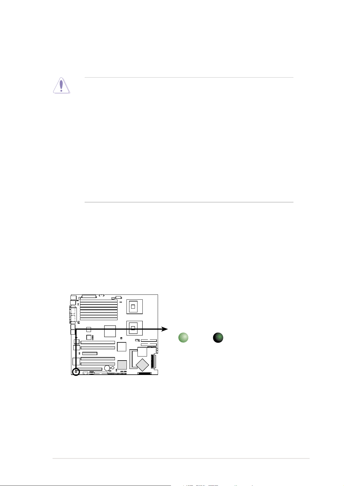
2.2.12.2.1
2.2.1
2.2.12.2.1
When installing the motherboard, make sure that you place it into the
chassis in the correct orientation. The edge with external ports goes to the
rear part of the chassis as indicated in the image below.
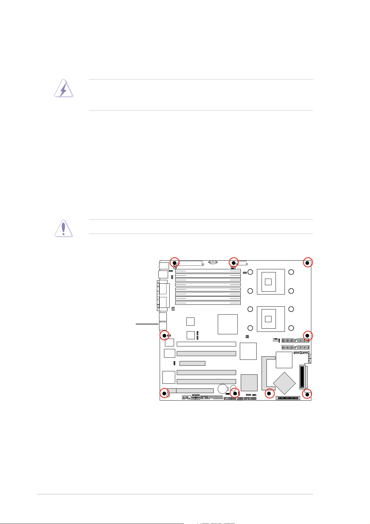
2.2.22.2.2
2.2.2
2.2.22.2.2
Place nine (9) screws into the holes indicated by circles to secure the
motherboard to the chassis.
Placement directionPlacement direction
Placement direction
Placement directionPlacement direction
Screw holesScrew holes
Screw holes
Screw holesScrew holes
Do not overtighten the screws! Doing so can damage the motherboard.
Place this side towardsPlace this side towards
Place this side towards
Place this side towardsPlace this side towards
the rear of the chassisthe rear of the chassis
the rear of the chassis
the rear of the chassisthe rear of the chassis
2-22-2
2-2
2-22-2
Chapter 2: Hardware informationChapter 2: Hardware information
Chapter 2: Hardware information
Chapter 2: Hardware informationChapter 2: Hardware information
2.2.32.2.3
2.2.3
2.2.32.2.3
CEK spring support for motherboardCEK spring support for motherboard
CEK spring support for motherboard
CEK spring support for motherboardCEK spring support for motherboard
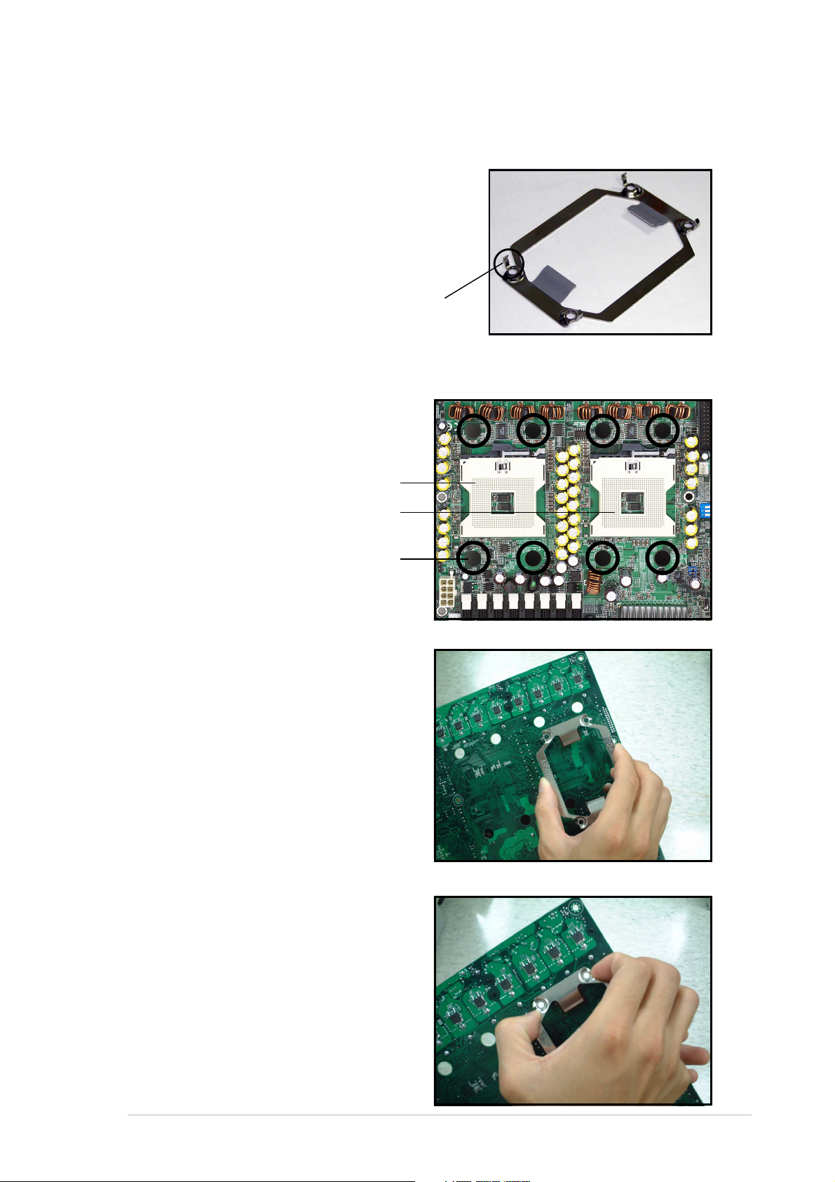
For additional protection from motherboard
breakage due to the weight of the CPU
heatsinks, your motherboard package comes
with two CEK springs. Each CEK spring has
four hooks to match the designated holes
around the CPU area.
HookHook
Hook
HookHook
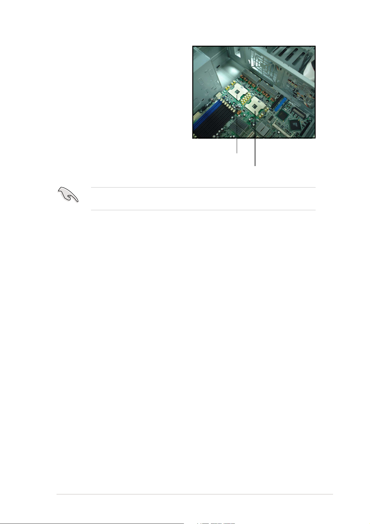
To install the CEK spring:
1. Locate the CPU heatsink holes
on the motherboard.
Socket for CPU1Socket for CPU1
Socket for CPU1
Socket for CPU1Socket for CPU1
Socket for CPU2Socket for CPU2
Socket for CPU2
Socket for CPU2Socket for CPU2
CEK springCEK spring
CEK spring
CEK springCEK spring
Heatsink holeHeatsink hole
Heatsink hole
Heatsink holeHeatsink hole
2. Position the CEK spring
underneath the motherboard,
then match the CEK spring
hooks to the CPU1 heatsink
holes.
3. Press the upper spring hooks
inward, then insert to the upper
CPU heatsink holes until they
snap in place.
ASUS NCL-DS SeriesASUS NCL-DS Series
ASUS NCL-DS Series
ASUS NCL-DS SeriesASUS NCL-DS Series
2-32-3
2-3
2-32-3
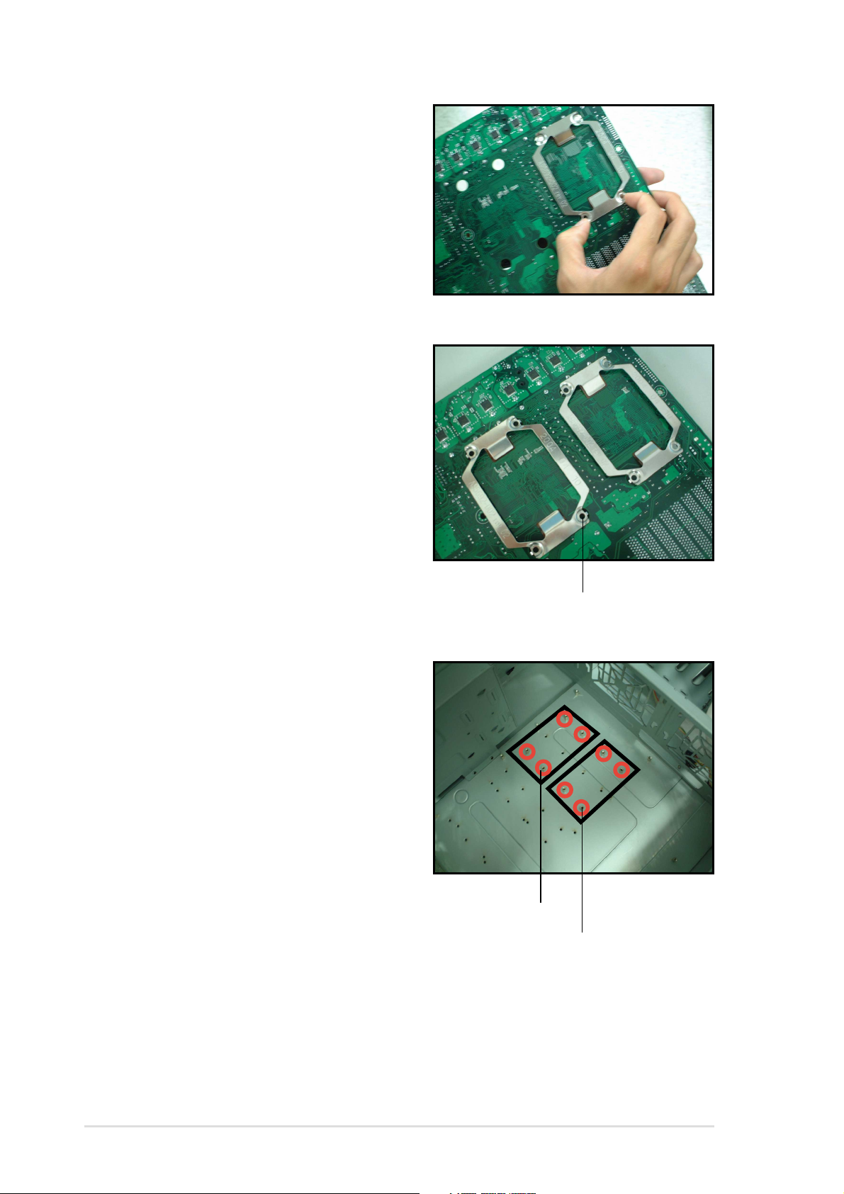
4. Press the lower spring clips
inward, then insert to the lower
CPU heatsink holes until they
snap in place.
5. If you installed a second CPU,
repeat steps 2 to 4 to install the
CEK spring to the CPU2 heatsink
holes.
The CEK springs appear as
shown when installed.
6. Before installing the
motherboard into the chassis,
locate the standoffs that should
match the eight (8) CEK spring
screw holes.
CEK spring screw holeCEK spring screw hole
CEK spring screw hole
CEK spring screw holeCEK spring screw hole
Standoffs for CPU1Standoffs for CPU1
Standoffs for CPU1
Standoffs for CPU1Standoffs for CPU1
Standoffs for CPU2Standoffs for CPU2
Standoffs for CPU2
Standoffs for CPU2Standoffs for CPU2
2-42-4
2-4
2-42-4
Chapter 2: Hardware informationChapter 2: Hardware information
Chapter 2: Hardware information
Chapter 2: Hardware informationChapter 2: Hardware information
7. Install the motherboard with the
external I/O ports toward the
chassis rear panel. The CPU
sockets should be right on top
of their respective standoffs.
Socket for CPU1Socket for CPU1
Socket for CPU1
Socket for CPU1Socket for CPU1
Make sure that the standoffs perfectly match the CEK spring screw
holes; otherwise, you can not install the CPU heatsinks properly.
Socket for CPU2Socket for CPU2
Socket for CPU2
Socket for CPU2Socket for CPU2
8. Secure the motherboard with 9 screws. Refer to section “2.2.2 Screw
holes” for illustration.
ASUS NCL-DS SeriesASUS NCL-DS Series
ASUS NCL-DS Series
ASUS NCL-DS SeriesASUS NCL-DS Series
2-52-5
2-5
2-52-5
2.2.42.2.4
2.2.4
2.2.42.2.4
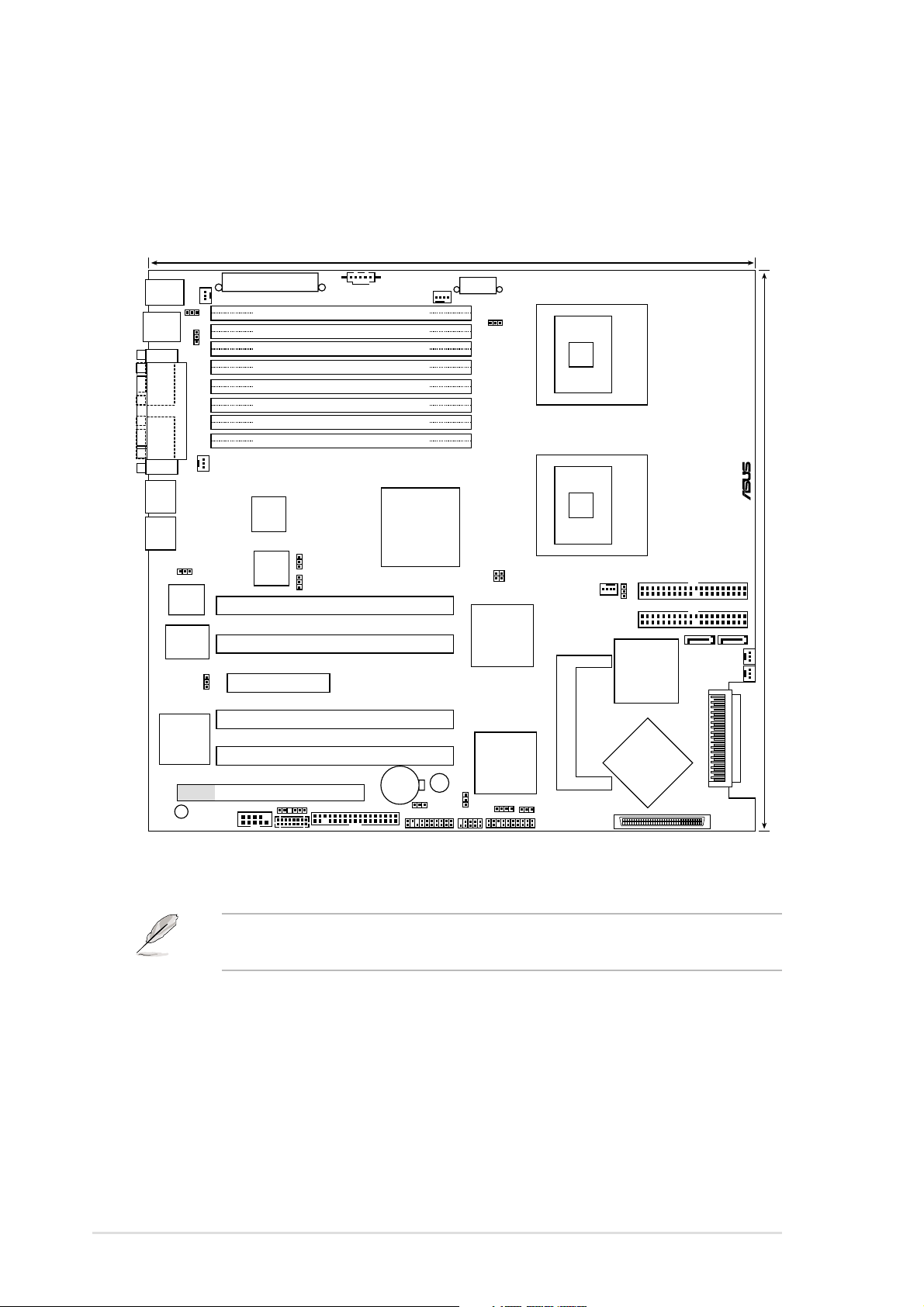
NCL-DS modelNCL-DS model
NCL-DS model
NCL-DS modelNCL-DS model
Motherboard layoutsMotherboard layouts
Motherboard layouts
Motherboard layoutsMotherboard layouts
33cm (13in)
PS/2
T: Mouse
B: Keyboard
USB1
USB2
COM1
VGA1
RJ-45
(LAN-1)
RJ-45
(LAN-2)
Super
RAGE XL
Controller
SB_PWR1
ATXPWR1
REAR_FAN2
KBPWR1
USBPW12
PARALLEL PORT
REAR_FAN1
RECPVERY1
AMI
8Mb
FWH
I/O
VGA_EN1
ATI
VGA
PCI6 (32-bit, 33MHz 5V)
COM2
PSUSMB1
DDR DIMM_B4 (64/72 bit, 240-pin module)
DDR DIMM_A4 (64/72 bit, 240-pin module)
DDR DIMM_B3 (64/72 bit, 240-pin module)
DDR DIMM_A3 (64/72 bit, 240-pin module)
DDR DIMM_B2 (64/72 bit, 240-pin module)
DDR DIMM_A2 (64/72 bit, 240-pin module)
DDR DIMM_B1 (64/72 bit, 240-pin module)
DDR DIMM_A1 (64/72 bit, 240-pin module)
Broadcom
BCM5721
CPU_FAN1
Intel E7520
MCH
Broadcom
BCM5721
LAN1_EN1
LAN2_EN1
PCIX1 (64-bit, 133MHz 3V)
PCIX2 (64-bit, 133MHz 3V)
PCIE3
PCIX4 (64-bit, 133MHz 3V)
PCIX5 (64-bit, 133MHz 3V)
CR2032 3V
Lithium Cell
BPSMB1
FLOPPY1
BMCCONN1
CMOS Power
AUX_PANEL1
BUZZ1
CLRTC1
ATX12V1
FM_CPU1
USBPW34
USB34
Intel
PXH
Intel
PXH
HDLED1
mPGA 604
®
mPGA 604
FRNT_FAN1
FRNT_FAN2
SCSIB1
3568
SCSIA1
NCL-DS
30.5cm (12in)
SATA1
FM_CPU2
SEC_IDE
PRI_IDE
SATA2
J2
CPU_FAN2
Intel
ICH5R
Adaptec
AIC-7902W
SCSI_EN1
PANEL1
34 1
2-62-6
2-6
2-62-6
The NCL-DS model includes Adaptec® AIC-7902W SCSI controller, SCSI
connectors, and Intel® PXH chipset to support the SCSI RAID feature.
Chapter 2: Hardware informationChapter 2: Hardware information
Chapter 2: Hardware information
Chapter 2: Hardware informationChapter 2: Hardware information
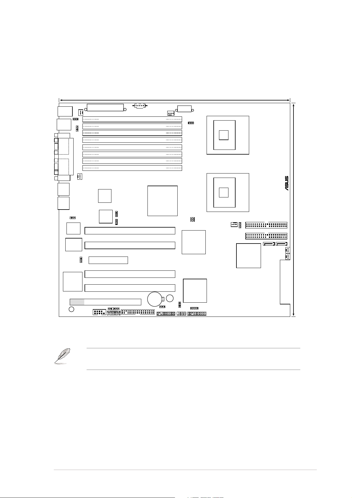
NCL-D modelNCL-D model
NCL-D model
NCL-D modelNCL-D model
33cm (13in)
PS/2
T: Mouse
B: Keyboard
USB1
USB2
COM1
VGA1
RJ-45
(LAN-1)
RJ-45
(LAN-2)
Super
RAGE XL
Controller
SB_PWR1
ATXPWR1
REAR_FAN2
DDR DIMM_B4 (64/72 bit, 240-pin module)
DDR DIMM_A4 (64/72 bit, 240-pin module)
DDR DIMM_B3 (64/72 bit, 240-pin module)
DDR DIMM_A3 (64/72 bit, 240-pin module)
DDR DIMM_B2 (64/72 bit, 240-pin module)
DDR DIMM_A2 (64/72 bit, 240-pin module)
DDR DIMM_B1 (64/72 bit, 240-pin module)
DDR DIMM_A1 (64/72 bit, 240-pin module)
Broadcom
BCM5721
USBPW12
PARALLEL PORT
AMI
8Mb
FWH
KBPWR1
REAR_FAN1
RECPVERY1
I/O
VGA_EN1
ATI
VGA
PCI6 (32-bit, 33MHz 5V)
COM2
PSUSMB1
Intel E7520
Broadcom
BCM5721
LAN1_EN1
LAN2_EN1
PCIX1 (64-bit, 133MHz 3V)
PCIX2 (64-bit, 133MHz 3V)
PCIE3
PCIX4 (64-bit, 133MHz 3V)
PCIX5 (64-bit, 133MHz 3V)
CR2032 3V
Lithium Cell
BPSMB1
FLOPPY1
BMCCONN1
CMOS Power
CPU_FAN1
MCH
AUX_PANEL1
BUZZ1
CLRTC1
ATX12V1
FM_CPU1
USBPW34
USB34
Intel
PXH
Intel
PXH
HDLED1
CPU1
CPU2
mPGA 604
®
mPGA 604
NCL-D
FM_CPU2
SEC_IDE
PRI_IDE
Intel
ICH5R
SATA2
30.5cm (12in)
SATA1
FRNT_FAN1
FRNT_FAN2
J2
CPU_FAN2
PANEL1
The NCL-D model supports RAID feature through the Intel
southbridge and two SATA connectors.
ASUS NCL-DS SeriesASUS NCL-DS Series
ASUS NCL-DS Series
ASUS NCL-DS SeriesASUS NCL-DS Series
®
ICH5R
2-72-7
2-7
2-72-7
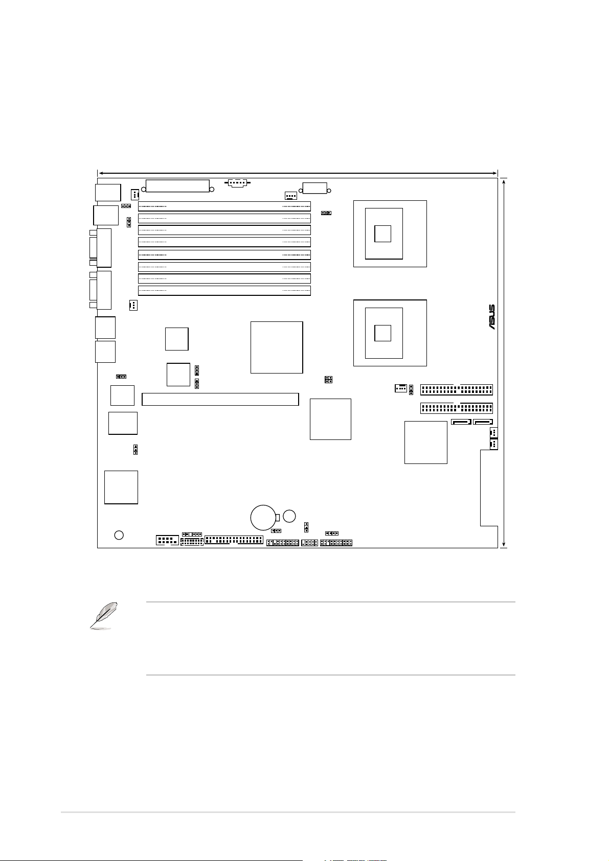
NCL-DR1 modelNCL-DR1 model
NCL-DR1 model
NCL-DR1 modelNCL-DR1 model
33cm (13in)
PS/2
T: Mouse
B: Keyboard
USB1
USB2
COM1VGA1
RJ-45
(LAN-1)
RJ-45
(LAN-2)
Super
RAGE XL
Controller
SB_PWR1
KBPWR1
USBPW12
AMI
8Mb
FWH
I/O
ATI
VGA
REAR_FAN2
REAR_FAN1
RECPVERY1
VGA_EN1
ATXPWR1
DDR DIMM_B4 (64/72 bit, 240-pin module)
DDR DIMM_A4 (64/72 bit, 240-pin module)
DDR DIMM_B3 (64/72 bit, 240-pin module)
DDR DIMM_A3 (64/72 bit, 240-pin module)
DDR DIMM_B2 (64/72 bit, 240-pin module)
DDR DIMM_A2 (64/72 bit, 240-pin module)
DDR DIMM_B1 (64/72 bit, 240-pin module)
DDR DIMM_A1 (64/72 bit, 240-pin module)
Broadcom
BCM5721
Broadcom
BCM5721
LAN1_EN1
LAN2_EN1
PCIX1 (64-bit, 133MHz 3V)
BPSMB1
FLOPPY1
COM2
BMCCONN1
PSUSMB1
CPU_FAN1
Intel E7520
MCH
CR2032 3V
Lithium Cell
CMOS Power
BUZZ1
CLRTC1
AUX_PANEL1
ATX12V1
FM_CPU1
USBPW34
USB34
Intel
PXH
HDLED1
mPGA 604
®
mPGA 604
SATA1
FRNT_FAN1
FRNT_FAN2
NCL-DR1
30.5cm (12in)
FM_CPU2
SEC_IDE
PRI_IDE
SATA2
J2
CPU_FAN2
Intel
ICH5R
PANEL1
2-82-8
2-8
2-82-8
• The NCL-DR1 model supports RAID feature through the Intel
®
ICH5R
southbridge and two SATA connectors.
• This PCI-X slot supports a 64-bit expansion card on a riser card for
1U systems.
Chapter 2: Hardware informationChapter 2: Hardware information
Chapter 2: Hardware information
Chapter 2: Hardware informationChapter 2: Hardware information
2.2.52.2.5
2.2.5
2.2.52.2.5
Layout contentsLayout contents
Layout contents
Layout contentsLayout contents
Slots/SocketsSlots/Sockets
Slots/Sockets
Slots/SocketsSlots/Sockets
PagePage
Page
PagePage
1. CPU sockets 2-9
2. DDR2 DIMM sockets 2-13
3. PCI/PCI-X/PCI Express slots 2-18
4. Zero-Channel RAID socket 2-18
JumpersJumpers
Jumpers
JumpersJumpers
PagePage
Page
PagePage
1. Clear RTC RAM (CLRTC1) 2-21
2. CPU fan pin selection (3-pin FM_CPU1, FM_CPU2) 2-22
3. USB device wake-up (3-pin USBPW12, USBPW34) 2-22
4. Keyboard power (3-pin KBPWR1) 2-23
5. VGA controller setting (3-pin VGA_EN1) 2-23
6. Gigabit LAN controller setting (3-pin LAN1_EN1) 2-24
7. Gigabit LAN controller setting (3-pin LAN2_EN1) 2-24
8. SCSI controller setting (3-pin SCSI_EN1) 2-25
9. Force BIOS recovery setting (3-pin RECOVERY1) 2-25
Rear panel connectorsRear panel connectors
Rear panel connectors
Rear panel connectorsRear panel connectors
PagePage
Page
PagePage
1. PS/2 mouse port (green) 2-26
2. Parallel port 2-26
3. LAN (RJ-45) ports 2-26
4. VGA port 2-26
5. Serial (COM1) port 2-26
6. USB 2.0 ports 1 and 2 2-26
7. PS/2 keyboard port (purple) 2-26
ASUS NCL-DS SeriesASUS NCL-DS Series
ASUS NCL-DS Series
ASUS NCL-DS SeriesASUS NCL-DS Series
2-92-9
2-9
2-92-9
Internal connectorsInternal connectors
Internal connectors
Internal connectorsInternal connectors
PagePage
Page
PagePage
1. Floppy disk drive connector (34-1 pin FLOPPY1) 2-27
2. Primary IDE connectors (40-1 pin PRI_IDE, SEC_IDE) 2-27
3. Serial ATA connectors (7-pin SATA1, SATA2) 2-28
4. Ultra320 SCSI connectors (two 68-pin SCSIA1, SCSIB1) 2-29
5. Hard disk activity LED connector (4-pin HDLED1) 2-30
6. USB connector (10-1 pin USB34) 2-30
7. CPU and system fan connectors
(3-pin CPU_FAN1/2, REAR_FAN1/2, FRNT_FAN1/2) 2-31
8. Power supply SMBus connector (5-pin PSUSMB1) 2-31
9. Backplane SMBus connector (6-1 pin BPSMB1) 2-32
10. Serial port connector (10-1 pin COM2) 2-32
11. ATX power connectors (24-pin ATXPWR1, 8-pin ATX12V1) 2-33
12. BMC connector (16-pin BMCCONN1) 2-33
13. System panel connector (20-pin PANEL1) 2-34
14. Auxiliary panel connector (20-pin AUX_PANEL1) 2-35
2-102-10
2-10
2-102-10
Chapter 2: Hardware informationChapter 2: Hardware information
Chapter 2: Hardware information
Chapter 2: Hardware informationChapter 2: Hardware information
 Loading...