

Page 1

J3455T-IM-A
N3350T-IM-A
N4200T-IM-A
Industrial Motherboard
Page 2

E17325
First Edition
November 2020
Copyright © 2020 ASUSTeK COMPUTER INC. All Rights Reserved.
No part of this manual, including the products and software described in it, may be reproduced,
transmitted, transcribed, stored in a retrieval system, or translated into any language in any form or by any
means, except documentation kept by the purchaser for backup purposes, without the express written
permission of ASUSTeK COMPUTER INC. (“ASUS”).
Product warranty or service will not be extended if: (1) the product is repaired, modied or altered, unless
such repair, modication of alteration is authorized in writing by ASUS; or (2) the serial number of the
product is defaced or missing.
ASUS PROVIDES THIS MANUAL “AS IS” WITHOUT WARRANTY OF ANY KIND, EITHER EXPRESS
OR IMPLIED, INCLUDING BUT NOT LIMITED TO THE IMPLIED WARRANTIES OR CONDITIONS OF
MERCHANTABILITY OR FITNESS FOR A PARTICULAR PURPOSE. IN NO EVENT SHALL ASUS, ITS
DIRECTORS, OFFICERS, EMPLOYEES OR AGENTS BE LIABLE FOR ANY INDIRECT, SPECIAL,
INCIDENTAL, OR CONSEQUENTIAL DAMAGES (INCLUDING DAMAGES FOR LOSS OF PROFITS,
LOSS OF BUSINESS, LOSS OF USE OR DATA, INTERRUPTION OF BUSINESS AND THE LIKE),
EVEN IF ASUS HAS BEEN ADVISED OF THE POSSIBILITY OF SUCH DAMAGES ARISING FROM ANY
DEFECT OR ERROR IN THIS MANUAL OR PRODUCT.
SPECIFICATIONS AND INFORMATION CONTAINED IN THIS MANUAL ARE FURNISHED FOR
INFORMATIONAL USE ONLY, AND ARE SUBJECT TO CHANGE AT ANY TIME WITHOUT NOTICE,
AND SHOULD NOT BE CONSTRUED AS A COMMITMENT BY ASUS. ASUS ASSUMES NO
RESPONSIBILITY OR LIABILITY FOR ANY ERRORS OR INACCURACIES THAT MAY APPEAR IN THIS
MANUAL, INCLUDING THE PRODUCTS AND SOFTWARE DESCRIBED IN IT.
Products and corporate names appearing in this manual may or may not be registered trademarks or
copyrights of their respective companies, and are used only for identication or explanation and to the
owners’ benet, without intent to infringe.
ii
Page 3

Contents
Chapter 1 Product overview
1.1 Package contents......................................................................... 1-1
1.2 Features ........................................................................................ 1-1
1.3 Specifications ............................................................................... 1-2
Chapter 2 Motherboard information
2.1 Before you proceed ..................................................................... 2-1
2.2 Motherboard layout ...................................................................... 2-2
2.3 Central Processing Unit (CPU) ................................................... 2-4
2.4 System memory ........................................................................... 2-5
2.5 Jumpers ........................................................................................ 2-6
2.6 Connectors ................................................................................. 2-10
2.6.1 Rear panel connectors .................................................. 2-10
2.6.2 Internal connectors ....................................................... 2-11
Chapter 3 BIOS setup
3.1 BIOS setup program .................................................................... 3-1
3.1.1 BIOS menu screen .......................................................... 3-2
3.2 Main menu .................................................................................... 3-2
3.2.1 System Date [Day MM/DD/YYYY] .................................. 3-2
3.2.2 System Time [HH:MM:SS] .............................................. 3-2
3.3 Advanced menu ........................................................................... 3-3
3.3.1 Platform Trust Technology .............................................. 3-3
3.3.2 Trusted Computing ......................................................... 3-3
3.3.3 CPU Conguration .......................................................... 3-3
3.3.4 Graphic Conguration ..................................................... 3-4
3.3.5 PCI Express Conguration .............................................. 3-6
3.3.6 CSM Conguration .......................................................... 3-7
3.3.7 Super IO Conguration ................................................... 3-7
3.3.8 Serial Console Redirection ............................................. 3-7
3.3.9 SATA Conguration ........................................................ 3-8
3.3.10 Network Stack Conguration .......................................... 3-8
3.3.11 USB Conguration .......................................................... 3-8
3.3.12 Onboard Devices Conguration ...................................... 3-9
3.3.13 Watchdog Timer ............................................................ 3-10
3.3.14 APM Conguration ........................................................ 3-10
iii
Page 4

3.3.15 EZ-Flash ....................................................................... 3-10
3.3.16 Miscellaneous ............................................................... 3-10
3.4 Hardware Monitor menu ............................................................ 3-11
3.5 Security menu ............................................................................ 3-11
3.6 Boot menu .................................................................................. 3-13
Boot Conguration ....................................................................... 3-13
FIXED BOOT ORDER Priorities ................................................. 3-13
3.7 Exit menu .................................................................................... 3-13
Save Changes & Exit ................................................................... 3-13
Discard Changes & Exit ............................................................... 3-14
Save Changes & Reset ................................................................ 3-14
Discard Changes & Reset ............................................................ 3-14
Save changes .............................................................................. 3-14
Discard changes .......................................................................... 3-14
Restore Defaults .......................................................................... 3-14
Save as User Defaults ................................................................. 3-14
Restore User Defaults .................................................................. 3-14
Appendix
Notices .......................................................................................................A-1
ASUS contact information .......................................................................A-5
iv
Page 5

Chapter 1
Product overview
1.1 Package contents
Check your industrial motherboard package for the following items.
1 x ASUS J3455T-IM-A/N3350T-IM-A/N4200T-IM-A Motherboard
1 x SATA 6.0 Gb/s cable
1 x SATA power cable
2 x M.2 screw packages
1 x ASUS I/O Shield
NOTE: If any of the above items is damaged or missing, contact your
distributor or sales representative immediately.
1.2 Features
• Built-in Intel® Celeron® Quad-core Processor J3455/N3350/N4200
• Two DDR3L 1866/1600/1333 MHz Non-ECC Un-buffered SO-DIMMs up to 8GB
• 2 x SATA 6Gb/s, 4 x USB 3.2 Gen 1, 2 x USB 2.0, 6 x COM headers
• 1 x PCIe 2.0 x1 slot (colay with M.2 E Key), 1 x Full/Half-size PCIe mini card
slot (w/SIM holder), 1 x M.2 Socket 1 with E key
• Multi-display: 1 x VGA, 1 x HDMI, 1 x DisplayPort++, 1 x LVDS, 1 x Embedded
DisplayPort (BOM colay with LVDS,optional), HDMI + VGA + LVDS,
VGA+HDMI+eDP, DP+HDMI+LVDS, DP+HDMI+eDP
Chapter 1: General information
1-1
Page 6
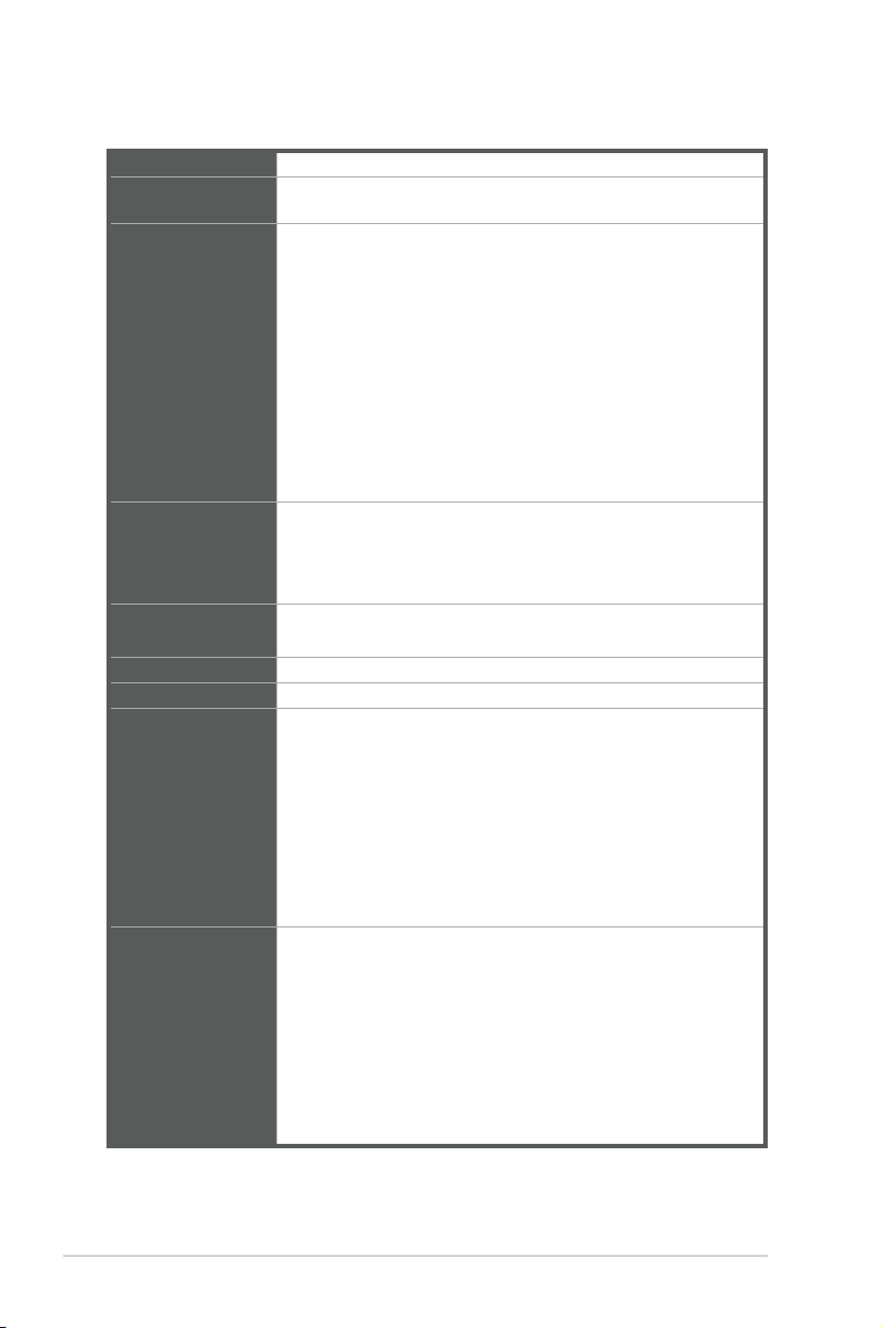
1.3 Specifications
CPU
Memory
Graphics
Expansion slots
Storage
Ethernet
Audio Realtek® ALC887 High Denition Audio
Rear panel I/O
ports
Internal
Connectors
Built-in Intel® Celeron® Quad-core Processor J3455/N3350/N4200
2 x DDR3L, max.8GB, DDR3L 1866/1600/1333 MHz Non-ECC,
Unbuffered Memory
Integrated graphics processor - Intel® HD Graphics support
- Supports VGA output with a maximum resolution of 1920 x
1200 @ 60Hz (colay with DisplayPort++)
- Supports HDMITM output with a maximum resolution of 3840
x 2160 @ 30Hz
- Supports DisplayPort++ output with a maximum resolution of
4096 x 2160 @ 30Hz
- Supports LVDS output with a maximum resolution of 1920 x
1200 @ 60Hz
- Supports Embedded DisplayPort output with a maximum
resolution of 4096 x 2160 @ 30Hz
Supports up to three displays simultaneously
1 x PCI Express 2.0 x1 slot (colay with M.2 E Key)
1 x Full/Half-size PCIe minicard slot (w/SIM holder)
1 x M.2 Socket 1 with E key, type 2230 for WIFI/BT device (colay
with PCIe)
2 x SATA Gen3.0 up to 6.0 Gb/s ports
1 x Full/Half-size mSATA slot (shared with Mini PCIe)
2 x Realtek® 8111H, supports WOL/PXE
1 x VGA port
1 x HDMITM port
1 x DisplayPort++
4 x USB 3.2 Gen 1 ports
2 x LAN (RJ45) ports
1 x P/S2 keyboard header
1 x Audio jack
1 x DC-IN jack
6 x Serial Port headers (5 x RS232, 1 x RS232/422/485)
1 x CPU Fan header (PWM Mode)
1 x Chassis Fan header (PWM Mode)
1 x Chassis intrusion header
1 x Front panel audio header (AAFP)
1 x System panel header (10-1 pin)
1 x Clear CMOS jumper
1 x LVDS header
1-2
(continued on the next page)
J3455T-IM-A/N3350T-IM-A/N4200T-IM-A
Page 7
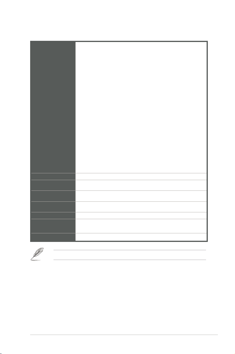
2 x USB 2.0 headers support additional 4 USB 2.0 ports
1 x 8-bit GPIO header
1 x LPC debug header
1 x 3-pin ATX power connector (5VSB)
1 x 4-pin ATX 12V power connector
1 x SATA power connector
2 x SATA ports
1 x Keyboard/Mouse header
Internal
Connectors
Manageability
Power
requirement
Operation
Temperature
Non-Operation
Temperature
Relative Humidity 0%~85%
OS support
Form Factor
1 x Speaker header
1 x eDP connector (optional)
1 x I2C header
1 x SPI TPM header
1 x WDT header
1 x AT/ATX selection header
1 x Flat Panel Display Brightness selection header
1 x Display Panel Backlight Power Selector
1 x Display Panel VCC Power Selector
1 x LCD panel monitor switch header
WfM 2.0, WOL by PME
AT/ATX mode and DC-IN (12V)
0~60°C
-40~85°C
Windows® 10 (64bit) / Windows® 10 IoT Enterprise
Ubuntu, RedHat Enterprise, Fedora Workstation, OpenSUSE
Thin Mini-ITX Form Factor, 6.7”x 6.7” (17.0cm x 17.0cm)
NOTE: Specications are subject to change without notice.
Chapter 1: General information
1-3
Page 8

Chapter 2
Motherboard information
2.1 Before you proceed
Take note of the following precautions before you install motherboard components
or change any motherboard settings.
CAUTION!
• Unplug the power cord from the wall socket before touching any
component.
• Before handling components, use a grounded wrist strap or touch a safely
grounded object or a metal object, such as the power supply case, to avoid
damaging them due to static electricity.
• Hold components by the edges to avoid touching the ICs on them.
• Whenever you uninstall any component, place it on a grounded antistatic
pad or in the bag that came with the component.
• Before you install or remove any component, always remove the AC power
by unplugging the power cord from the power outlet. Failure to do so may
cause severe damage to the motherboard, peripherals, or components.
Chapter 2: Motherboard information
2-1
Page 9
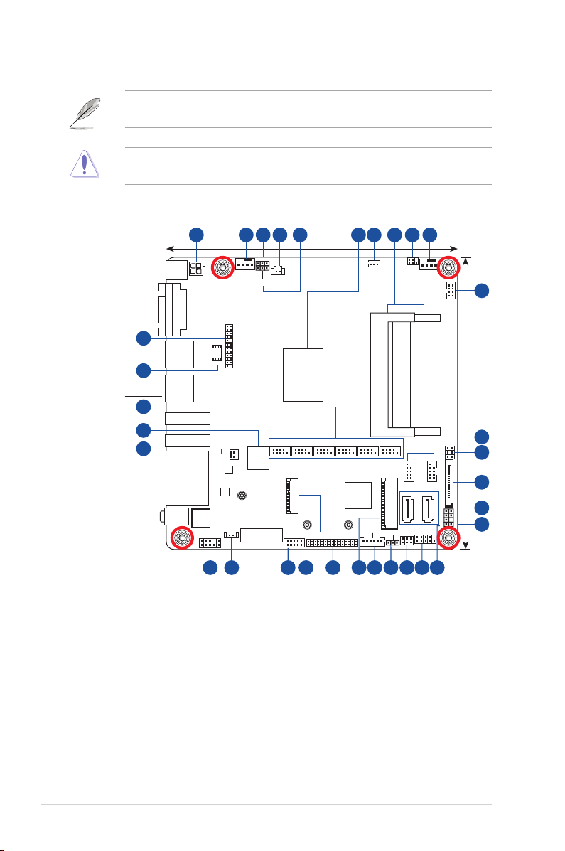
2.2 Motherboard layout
NOTE: Place four screws into the holes indicated by circles to secure the
motherboard to the chassis.
CAUTION! Do not overtighten the screws! Doing so can damage the
motherboard.
Place this side
towards the rear
of the chassis
31
30
29
28
27
1 2 3 4 5 7 8 9 26
LPC_DEBUG
8Mb
BIOS
SPI_TPM
PANEL_SW
Realtek
8111H
Realtek
8111H
BATTERY
CPU_FAN
®
®
WDT_EN
AT_ATX_SEL
NANO_SIM
PCIEX1
CLRTC
GPIO_CON
24
Intel
J3455/
N3350/
N4200
SoC
M.2(WIFI)
DC_PWR
VGA
U32G1_12
U32G1_34
HDMI
LAN1_LAN2
AUDIO
ATX12V
DP
ALC
887
AAFP
26 25
17.0cm(6.7in)
®
LVDS_EDP
22
23
I2C
ATX_5VSB
DDR3L So-DIMM_B1 (64bit, 204-pin module)
DDR3L So-DIMM_A1 (64bit, 204-pin module)
COM1COM2COM3COM4COM5COM6
20
USBE34
MPCIE_MSATA
VCC_PWR_SEL
BKLPWR_SEL
19
18
Super
I/O
21
LCD_BLKT_PANEL
CHA_FAN
USBE12
SATA6G_2
F_PANEL
17
KBMS_CON
J3455T-IM-A
COM1_SEL
SATA_PWRCON
SATA6G_1
SPEAKER
16
17.0cm(6.7in)
CHASSIS
10
11
12
13
14
15
2-2
J3455T-IM-A/N3350T-IM-A/N4200T-IM-A
Page 10

Connectors/Jumpers/Slots Page
1. ATX Power connector (4-pin ATX12V) 2-11
2. CPU and Chassis fan headers (4-pin CPU_FAN, 4-pin CHA_FAN) 2-11
3. WDT Enbale jumper (2-pin WDT_EN) 2-7
4. Clear RTC RAM (2-pin CLRTC) 2-6
5. AT/ATX mode selection (3-pin AT_ATX_SEL) 2-7
6. Built-in Intel® Celeron® Quad-core Processor J3455/N3350/N4200 2-4
7. ATX 5V Standby Power header (3-pin ATX_5VSB) 2-12
8. DDR3L SO-DIMM slots 2-5
9. I2C header (6-1 pin I2C) 2-12
10. PS/2 Keyboard and Mouse header (8-pin KBMS_CON) 2-13
11. USB 2.0 headers (10-1pin USB_E12, USB_E34) 2-13
12. COM RING/+5V/+12V selection (6-pin COM1_SEL) 2-8
13. SATA Power connector (SATA_PWRCON) 2-14
14. SATA 6.0 Gb/s ports (7-pin SATA6G_1/2) 2-14
15. Chassis Intrusion header (4-pin CHASSIS) 2-8
16. Speaker header (4-1 pin SPEAKER) 2-15
17. System Panel header (10-1 pin F_PANEL) 2-16
18. Display panel VCC power selection (6-pin VCC_PWR_SEL) 2-9
19. Display panel backlight power selection (3-pin BKLT_PWR_SEL) 2-9
20. Flat panel display brightness header (6-pin LCD_BLKT_PANEL) 2-17
21. mSATA/mPCIe combo slot (MPCIE_MSATA) 2-17
22. LVDS/EDP connector (30-pin LVDS_EDP) 2-18
23. M.2 Wi-Fi slot 2-18
24. General Purpose Input/output header (GPIO_CON) 2-19
25. RTC Battery header (2-pin BATTERY) 2-19
26. Front Panel Audio header (10-1 pin AAFP) 2-20
27. Panel switch (2-pin PANEL_SW) 2-20
28. Nano SIM Card slot 2-21
29. COM Port headers (10-1 pin COM1~COM6) 2-21
30. SPI_TPM header (14-1 pin SPI_TPM) 2-22
31. LPC Debug header (10-1 LPC_DEBUG) 2-22
Chapter 2: Motherboard information
2-3
Page 11
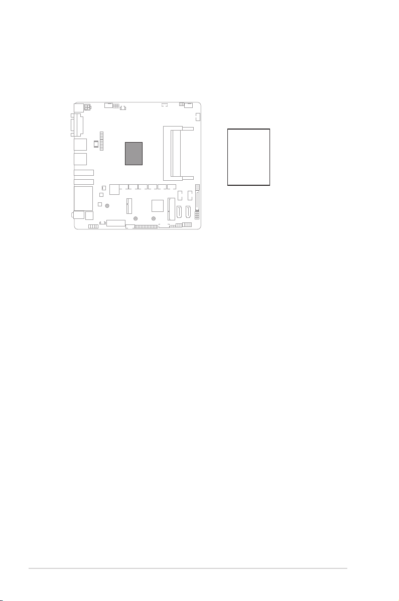
2.3 Central Processing Unit (CPU)
The motherboard comes with an onboard Intel
N3350/N4200.
®
Celeron® Quad-core processor J3455/
®
Intel
J3455/
N3350/
J3455T-IM-A
N4200
SoC
2-4
J3455T-IM-A/N3350T-IM-A/N4200T-IM-A
Page 12
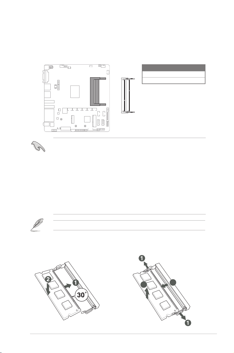
2.4 System memory
J3455T-IM-A
DIMM_B1
DIMM_A1
3
2
This motherboard comes with two Double Data Rate 3 Low Voltage (DDR3L) Small
Outline Dual Inline Memory Modules (SO-DIMM) socket. The gure illustrates the
location of the DDR3L DIMM socket:
Channel
Channel A DIMM_A1
Channel B DIMM_B1
IMPORTANT!
• You may install varying memory sizes in Channel A and Channel B. The
system maps the total size of the lower-sized channel for the dual-channel
conguration. Any excess memory from the higher-sized channel is then
mapped for single-channel operation.
• Always install the DIMMS with the same CAS Latency. For an optimum
compatibility, we recommend that you install memory modules of the same
version or data code (D/C) from the same vendor. Check with the vendor to
get the correct memory modules.
• According to Intel® CPU spec, DIMM voltage below 1.35V is recommended
to protect the CPU.
NOTE: Visit the ASUS website at www.asus.com for the latest QVL.
Sockets
To install a SO-DIMM
Chapter 2: Motherboard information
To remove a SO-DIMM
2
3
2-5
Page 13
2.5 Jumpers
1. Clear RTC RAM (2-pin CLRTC)
This header allows you to clear the CMOS RTC RAM data of the system
setup information such as date, time, and system passwords.
CLRTC
Connector type
J3455T-IM-A
HEADER 1x2p, 2.54mm pitch, S/T
GND
+3V_BAT
To erase the RTC RAM:
1. Turn OFF the computer and unplug the power cord.
2. Use a metal object such as a screwdriver to short the two pins.
3. Plug the power cord and turn ON the computer.
4. Hold down the <Del> key during the boot process and enter BIOS setup
to re-enter data.
NOTE: If the steps above do not help, remove the onboard battery and move
the jumper again to clear the CMOS RTC RAM data. After clearing the CMOS,
reinstall the battery.
2-6
J3455T-IM-A/N3350T-IM-A/N4200T-IM-A
Page 14
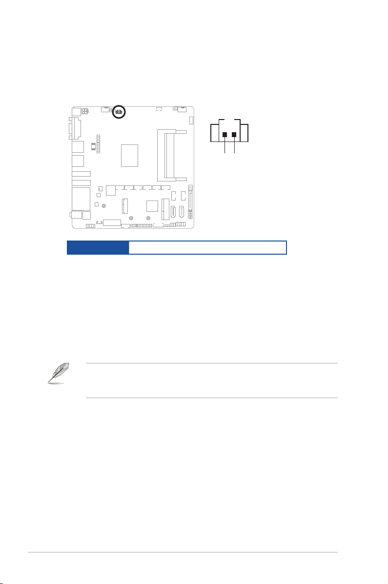
2. WDT Enable jumper (2-pin WDT_EN)
A watchdog timer is an electronic timer that is used to detect and recover
from computer malfunctions. The HW WDT (watchdog timer) Enable jumper
allows the HW watchdog resets the system automatically even when the
system crashes.
WDT_EN
21 2 3
jumper closed
(Default)
J3455T-IM-A
Connector type
NOTE: By default, this jumper is set to HW WDT enabled with a jumper cap
attached.
HEADER 1x2p, 2.54mm pitch, S/T
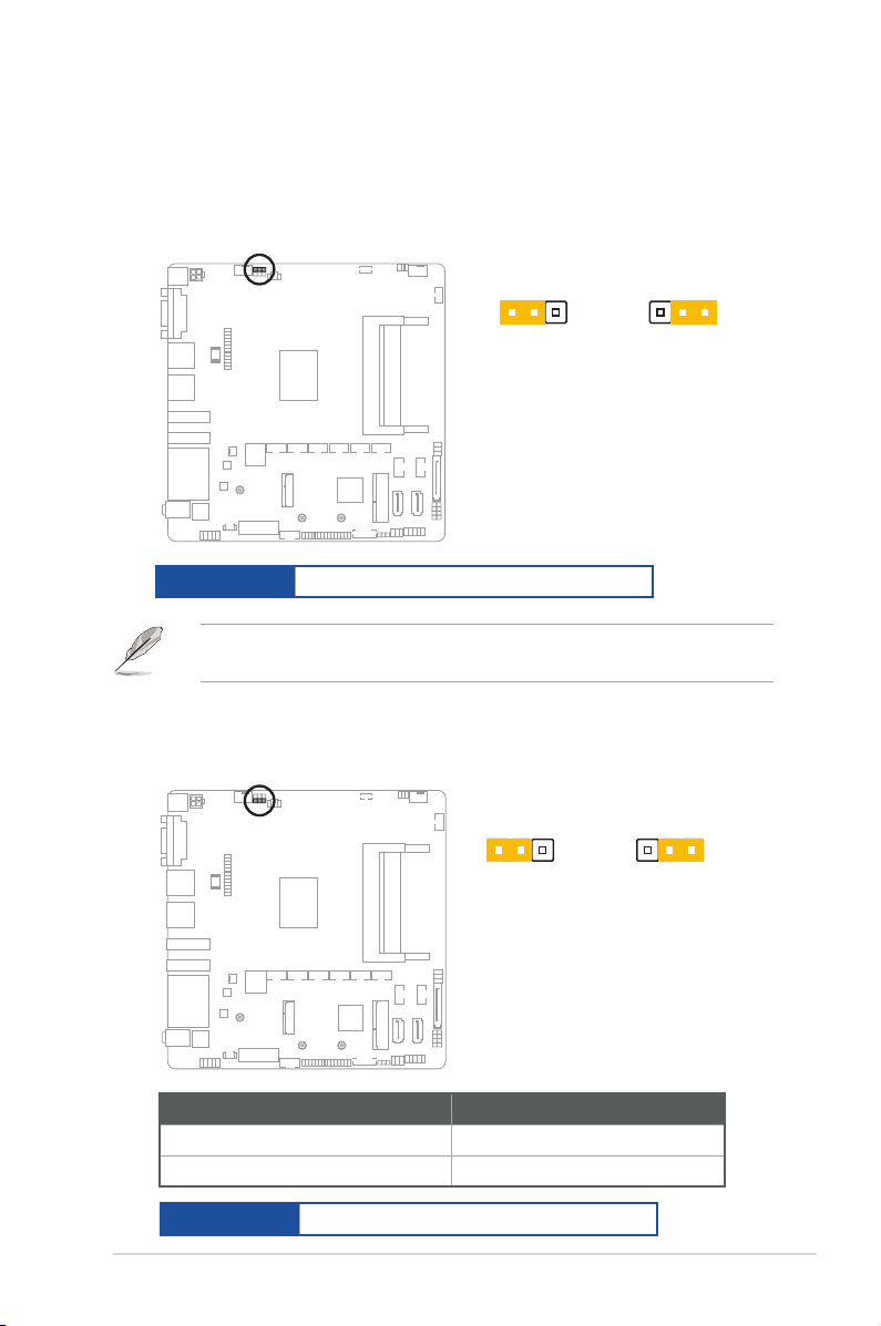
3. AT/ATX mode selection (3-pin AT_ATX_SEL)
AT_ATX_SEL
21 2 3
jumper closed
(Default)
J3455T-IM-A
jumper removed
jumper removed
Pins
1-2 (Default) ATX mode
2-3 AT mode
Connector type
HEADER 1x3p, 2.54mm pitch, S/T
Chapter 2: Motherboard information
2-7
Page 15
J3455T-IM-A
PIN 1
GND
O_CASEOPEN
+5VSB_ATX
CHASSIS
4. COM Ring/+5V/+12V selection (6-pin COM1_SEL)
COM1_SEL
J3455T-IM-A
12 34 56
+5V+12V
RI
(Default)
Setting Pins
12V 1-2
5V 3-4
Ring (Default) 5-6
5. Chassis intrusion header (4-1 pin_CHASSIS)
This header is for a chassis-mounted intrusion detection sensor or switch. Connect
one end of the chassis intrusion sensor or switch cable to this connector. The
chassis intrusion sensor or switch sends a low-level signal to this connector
when a chassis component is installed. The signal is then generated as a chassis
intrusion event.
2-8
Connector type
HEADER 4p, K2, 2.54mm pitch
J3455T-IM-A/N3350T-IM-A/N4200T-IM-A
Page 16

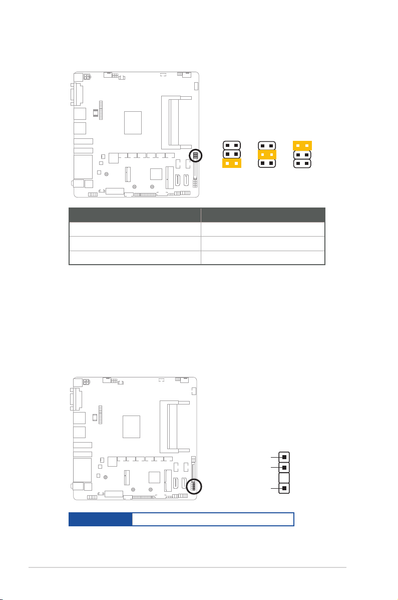
6. Display panel VCC power selection (6-pin VCC_PWR_SEL)
J3455T-IM-A
1
3V
(Default)
2
5V
3
12V
VCC_PWR_SEL
J3455T-IM-A
21 2 3
12V
(Default)
5V
BKLPWR_SEL
Setting Pins
12V 1.4.5-6
5V 1.4.5-3
3V (Default) 1.4.5-2
Connector type
HEADER 1 x 3p, 2.54mm pitch, S/T
7. Display panel backlight power selection (3-pin BKLT_PWR_SEL)
Pins
12V (Default) 1-2
5V 2-3
Connector type
HEADER 1x3p, 2.54mm pitch, S/T
Chapter 2: Motherboard information
2-9
Page 17

2.6 Connectors
2.6.1 Rear panel connectors
3 1
62 4 5 7
1. DC power connector. Insert the power adapter into this port.
2. Video Graphics Adapter (VGA) ports. These 15-pin ports are for VGA
monitors or other VGA-compatible devices.
3. USB 3.2 Gen 1 (up to 5Gbps) ports. These 9-pin Universal Serial Bus
(USB) ports are for USB 3.2 Gen 1 devices.
4. HDMI port. This port is for a High-Denition Multimedia Interface (HDMI)
connector, and is HDCP compliant allowing playback of HD DVD, Blu-Ray,
and other protected content.
5. DisplayPort port. This port connects a device with DisplayPort connector.
6. LAN (RJ-45) ports. These ports allow Gigabit connection to a Local Area
Network (LAN) through a network hub.
LAN port LED indications
LAN port
Speed
LED
Activity/Link LED Speed LED
Status Description Status Description
Off No link OFF 10Mbps connection
Orange Linked ORANGE 100Mbps connection
Orange (Blinking) Data activity GREEN 1Gbps connection
Orange (Blinking
then steady)
Ready to wake
up from S5 mode
Activity Link
LED
7. Audio port. This port connects to audio devices.
2-10
J3455T-IM-A/N3350T-IM-A/N4200T-IM-A
Page 18

2.6.2 Internal connectors
J3455T-IM-A
PIN 1
ATX12V
+12V_CPU
+12V_CPU
GND
GND
1. ATX Power connector (4-pin ATX12V)
Correctly orient the ATX power supply plug into this connector and push
down rmly until the connector completely ts.
2. CPU and Chassis Fan headers (4-pin CPU_FAN, 4-pin CHA_FAN)
Connect the fan cables to the fan headers on the motherboard, ensuring that
the black wire of each cable matches the ground pin of the header.
A
Connector type
CAUTION: Do not forget to connect the fan cables to the fan headers.
Insufcient air flow inside the system may damage the motherboard
components. These are not jumpers! Do not place jumper caps on the fan
WAFER HD 4p, 2.54mm pitch, S/T
headers!
Chapter 2: Motherboard information
B
J3455T-IM-A
A
CPU_FAN
O_CPUFANIN_R
O_CPUFAN_PWM_Q
12V
GND
B
CHA_FAN
O_CHAFANIN_R
O_CHAFAN_PWM_Q
12V
GND
2-11
Page 19

3. ATX 5V Standby Power header (3-pin ATX_5VSB)
This header is for ATX 5V standby power.
ATX_5VSB
PIN 1
J3455T-IM-A
GND
+5VSB_IN
ATX_PSON#_R
4. I2C header
The I2C (Inter-Integrated Circuit) header allows you to connect an I
compatible IoT security module.
I2C
+3V
NC
PIN 1
J3455T-IM-A
GND
I2C1_SCL
I2C1_SDA
2
C
2-12
Connector type
Header 2x3p, K6, 2.0mm pitch
J3455T-IM-A/N3350T-IM-A/N4200T-IM-A
Page 20

J3455T-IM-A
+5V_ZPS2
GND
O_MS_DATA_R
O_MS_CLK_R
+5V_ZPS2
GND
O_KB_DATA_R
O_KB_CLK_R
KBMS_CON
PIN 1
5. PS/2 Keyboard/mouse header (6-pin KBMS_CON)
J3455T-IM-A
USB_E34
USB_E12
A B
A
B
PIN 1
GND
U2H_DP4
U2H_DN4
+5V_U2H_P34
NC
GND
U2H_DP3
U2H_DN3
+5V_U2H_P34
This header is for an IBM PS/2-compatible keyboard or mouse.
6. USB 2.0 headers (10-pin USBE12, USBE34)
These headers are for USB 2.0 ports. Connect the USB cables to these
headers. These USB headers comply with USB 2.0 specication that
supports up to 480 Mbps connection speed.
Connector type
Header 2x5p, K9, 2.54mm pitch
CAUTION! Never connect a 1394 cable to the USB headers. Doing so will
damage the motherboard.
NOTE: The USB cables are purchased separately.
Chapter 2: Motherboard information
2-13
Page 21

7. SATA Power connector (15-pin SATA_PWRCON)
J3455T-IM-A
SATA6G_1
SATA6G_2
GND
RSATA_RXP
RSATA_RXN
GND
RSATA_TXN
RSATA_TXP
GND
A B
A
B
This connector is for the SATA power cable. The power cable plug is
designed to t this connector in only one orientation. Find the proper
orientation and push down rmly until the connector completely t.
SATA_PWRCON
PIN 1
J3455T-IM-A
IMPORTANT: The SATA power connector supports 1A current to the
maximum.
8. SATA 6.0 Gb/s ports (7-pin SATA6G_1/2)
These ports connect to SATA 6.0 Gb/s hard disk drives or an optical drive via
SATA 6.0 Gb/s signal cables.
+12V
+12V
+12V
GND
GND
GND
+5V
+5V
+5V
GND
GND
GND
+3V
+3V
+3V
2-14
Connector type
WAFER HD 7p, 1.27mm pitch
J3455T-IM-A/N3350T-IM-A/N4200T-IM-A
Page 22

9. Speaker header (4-pin SPEAKER)
The 4-pin header is for the chassis-mounted system warning speaker. The
speaker allows you to hear system beeps and warnings.
Connector type
J3455T-IM-A
SPEAKER
SPKO
GND
GND
+5V_SPKO
HEADER 1x4p, 2.54mm pitch, S/T
PIN 1
Chapter 2: Motherboard information
2-15
Page 23

10. System Panel header (10-1 pin F_PANEL)
J3455T-IM-A
F_PANEL
PIN 1
PWR_BTN
PLED+
PLED-
PWRBTN#_PANEL
GND
HDLED+
HLED-_R
GND
O_RSTCON#_PR
+5V_FPANEL
+PWR_LED
+HDD_LED RESET
This header supports several chassis-mounted functions.
Connector type
Header 2x5p, K10, 2.54mm pitch
• System power LED (2-pin +PWR_LED)
This 2-pin header is for the system power LED. Connect the chassis power
LED cable to this header. The system power LED lights up when you turn on
the system power, and blinks when the system is in sleep mode.
•
Hard disk drive activity LED (2-pin +HDD_LED)
This 2-pin header is for the HDD Activity LED. Connect the HDD Activity LED
cable to this header. The IDE LED lights up or flashes when data is read from
or written to the HDD.
•
ATX power button/soft-off button (2-pin PWR_BTN)
This 2-pin header is for the system power button.
•
Reset button (2-pin RESET)
This 2-pin header is for the chassis-mounted reset button for system reboot
without turning off the system power.
2-16
J3455T-IM-A/N3350T-IM-A/N4200T-IM-A
Page 24

11. Flat panel display brightness header (8-pin LCD_BLKT_PANEL)
J3455T-IM-A
LCD_ENABKLT_CN_SW
H_LCD_BL_PWM_SW
BLKT_PWR
BLKT_PWR
GND
GND
PIN1
LCD_BLKT_PANEL
This header is for the LCD panel brightness controls.
Connector type
WAFER 6p, 2.0mm pitch
12. MPCIE/MSATA combo slot (MPCIE_MSATA)
This slot allows you to install a full length mSATA or mini-PCIe card,
providing you with expandability and connectivity solutions for an optimal
system performance.
MSATA_MPCIE
NP_NC2
NP_NC1
GND14
GND13
3.3V_2
mSATA_Present
GND12
Reserved9
1.5V_3
Reserved8
NC
Reserved7
NC
NC
3.3V
GND11
3.3V
USB_D+
GND
USB_D-
GND6
GND10
PETp0
SMB_DATA
PETn0
SMB_CLK
GND5
PIN 1
mPCIE_mSATA_SW
J3455T-IM-A
1.5V_2
GND4
GND9
PERn0
3.3V
PERp0
PERST#
GND3
W_DISABLE#
Reserved
GND8
Reserved
UIM_VPP
GND2
UIM_RESET
REFCLK+
UIM_CLK
REFCLKUIM_DATA
GND1
UIM_PWR
CLKREQ#
1.5V_1
Reserved2
GND7
Reserved1
3.3V_1
WAKE#
Chapter 2: Motherboard information
2-17
Page 25

J3455T-IM-A
M.2(WIFI)
PIN 1
GND
S_USB_PP10_CN
S_USB_PN10_CN
GND
S_CNV_WR_D1_N
S_CNV_WR_D1_P
GND
S_CNV_WR_D0_N
S_CNV_WR_D0_P
GND
S_CNV_WR_CLK_N
S_CNV_WR_CLK_P
Key
Key
Key
Key
GND
S_WIFI_TXP_C
S_WIFI_TXN_C
GND
S_WIFI_RXP
S_WIFI_RXN
GND
CK_WIFI_CLKP
CK_WIFI_CLKN
GND
CK_REQ_M2_WLAN#_R
S_WAKE#_WIFI
GND
S_CNV_WT_D1_N
S_CNV_WT_D1_P
GND
S_CNV_WT_D0_N
S_CNV_WT_D0_P
GND
S_CNV_WT_CLK_N
S_CNV_WT_CLK_P
GND
+3VSB_WIFI
+3VSB_WIFI
NC
M.2_BT_PCMCLK
S_CNV_RF_RESET_N
M.2_BT_PCMIN
S_XTAL_CLKREQ
NC
GND
NC
S_CNV_BRI_RSP
Key
Key
Key
Key
S_CNV_RGI_DT
S_CNV_RGI_RSP
S_CNV_BRI_DT
CL_RST#
CL_DATA
CL_CK
CNVI_GNSS_R
MFUART2_TXD_R
MFUART2_RXD_R
S_SUSCLK_R
S_PLTRST#
S_BT_DISABLE_N
S_WIFI_DISABLE_N
NC
NC
NC
CNV_CLKIN_XTAL_R
NC
NC
NC
+3VSB_WIFI
+3VSB_WIFI
13. LVDS/EDP header (30-pin LVDSEDP)
LVDS_EDP
This header is for an internal LVDS or embedded DisplayPort connection.
LCD_VCC
GND
GND
LVDS_TX_TA0P_SW
LVDS_TX_TB0P
LVDS_TX_TC0P_SW
GND
LVDS_TX_TCLK0P
LVDS_TX_TD0P_SW
LVDS_TX_TA1P_SW
LVDS_TX_TB1P
PIN 1
LVDS_TX_TC1P
GND
LVDS_TX_TCLK1P
LVDS_TX_TD1P_SW
14. M.2 Wi-Fi
2-18
J3455T-IM-A
LCD_VCC
LCD_VCC
This slot connects to an M.2 Wi-Fi device.
NOTE: The M.2 Wi-Fi module is purchased separately.
J3455T-IM-A/N3350T-IM-A/N4200T-IM-A
GND
LVDS_TX_TB0N
LVDS_TX_TA0N_SW
LVDS_TX_TC0N_SW
LVDS_TX_TB1N
LVDS_TX_TCLKON
LVDS_TX_TA1N_SW
LVDS_TX_TD0N_SW
LVDS_Detect/EDP_HPD
GND
LVDS_TX_TC1N
LVDS_TX_TCLK1N
LVDS_TX_TD1N_SW
Page 26

15. General Purpose Input/output header (GPIO_CON)
PIN 1
This header is for a general purpose input/output module which allows you to
customize the digital signal input/output.
GPIO_CON
GND
GPIO8
GPIO6
GPIO4
GPIO7
GPIO5
GPIO3
5V_GPIO
GPIO2
PIN 1
GPIO1
J3455T-IM-A
Connector type
WAFER HD 2x5p, 2.0mm pitch, S/T
16. Battery header (2-pin BATTERY)
This header is for the lithium CMOS battery.
J3455T-IM-A
BATTERY
+BAT
GND
Chapter 2: Motherboard information
2-19
Page 27

J3455T-IM-A
PIN 1
GND
MON_SW#
PANEL_SW
17. Front Panel Audio header (10-1 pin AAFP)
J3455T-IM-A
AAFP
PIN 1
GNDNCA_JD_FMIC1
A_JD_HPOUT
A_FMIC1_L
A_FMIC1_R
A_HPOUT_R
A_JD_FRONT
A_HPOUT_L
This header is for a chassis-mounted front panel audio I/O module that
supports HD Audio standard. Connect one end of the front panel audio I/O
module cable to this header.
Connector type
HEADER 2x5p, K8, 2.54mm pitch
IMPORTANT!
• We recommend that you connect a high-denition front panel audio module
to this header to avail of the motherboard’s high-denition audio capability.
• If you want to connect a high-denition front panel audio module to this
header, set the HD Audio Controller item in the BIOS setup to [Enabled].
18. Panel switch (2-pin PANEL_SW)
This 2-pin header is for connecting a monitor switch that can turn off the LCD
panel display backlight.
2-20
J3455T-IM-A/N3350T-IM-A/N4200T-IM-A
Page 28

19. NANO SIM Card slot
NANO_SIM
J3455T-IM-A
COM6
COM5
COM4
COM3
COM2
COM1
PIN 1
RXD
DTR#
DSR#
CTS#
DCD#
TXD
GND
RTS#
Ring
A
B
C
D
E
F
ABCDE
F
This slot connects to a NANO SIM card.
J3455T-IM-A
20. COM Port header (10-pin COM1~COM6)
This header is for a serial (COM) port. Connect the serial port cable to this
header, then install the module to a slot opening at the back of the system
chassis.
Connector type
NOTE: The serial port cable is purchased separately.
Chapter 2: Motherboard information
BOX header 2x5p, K10, 2.54mm pitch
2-21
Page 29

21. SPI TPM header (14-1 pin TPM)
J3455T-IM-A
PIN 1
+VCC_SPI_TPM
S_PLTRST#
NC
+1.8V_SPI_BIOS
S_SPI_CS0#
T_SPI_MISO
T_SPI_HOLD#
S_SPI_TPM_IRQ#
S_SPI_TPM_CS2#
T_SPI_BIOS_WP#
GND
T_SPI_CLK
T_SPI_MOSI
SPI_TPM
This header supports a Trusted Platform Module (TPM) system with a
Serial Peripheral Interface (SPI), allowing you to securely store keys, digital
certicates, passwords, and data. A TPM system also helps enhance network
security, protects digital identities, and ensures platform integrity.
Connector type
22. LPC Debug header
This header allows connection to a LPC Debug card.
Connector type
IMPORTANT!
• Scan the QR code to view the meaning of each debugging code.
• Debugging codes are only available for ASUS LPC Debug cards.
• Contact your region sales representative for LPC Debug cards ordering.
2-22
Header 2x7p, K14, 2.0mm pitch
SLAD0_SIO
SLAD1_SIO
SLAD2_SIO
SLAD3_SIO
J3455T-IM-A
S_LFRAME#
HEADER 2x5p, K10, 2.0mm pitch
J3455T-IM-A/N3350T-IM-A/N4200T-IM-A
LPC_DEBUG
PIN 1
+3V
+3V
CK_24M_DEBUG_LPC
GND
Page 30

Chapter 3
BIOS setup
Scan the QR code to view the BIOS update guide.
3.1 BIOS setup program
Use the BIOS Setup program to update the BIOS or congure its parameters. The
BIOS screens include navigation keys and brief online help to guide you in using
the BIOS Setup program.
Entering BIOS Setup at startup
To enter BIOS Setup at startup:
Press <Delete> or <F2> during the Power-On Self Test (POST). If you do not
press <Delete> or <F2>, POST continues with its routines.
Entering BIOS Setup after POST
To enter BIOS Setup after POST:
• Press <Ctrl>+<Alt>+<Del> simultaneously.
• Press the reset button on the system chassis.
• Press the power button to turn the system off then back on. Do this option only
if you failed to enter BIOS Setup using the rst two options.
NOTE: Using the power button, reset button, or the <Ctrl>+<Alt>+<Del> keys
to reboot a running operating system can cause damage to your data or system.
Always shut down the system properly from the operating system.
IMPORTANT:
• Visit the ASUS website at www.asus.com to download the latest BIOS le
for this motherboard.
• The default BIOS settings for this motherboard apply to most working
conditions and ensures optimal performance. If the system becomes
unstable after changing any BIOS settings, load the default settings to
regain system stability. Select the option Restore Defaults under the Exit
Menu or press hotkey F3.
• The BIOS setup screens shown in this section are for reference purposes
only, and may not exactly match what you see on your screen.
Chapter 3: BIOS setup
3-1
Page 31

3.1.1 BIOS menu screen
Menu bar
The menu bar on top of the screen has the following main items:
Main For changing the basic system conguration
Advanced For changing the advanced system settings
Hardware
Monitor
Security For conguring the system security settings
Boot For changing the system boot conguration.
Exit
To select an item on the menu bar, press the right or left arrow key on the
keyboard until the desired item is highlighted.
For displaying the system temperature and changing the
fan settings
For selecting the save options and default options.
3.2 Main menu
The Main menu provides you an overview of the basic system information, and
allows you to set the system date, time, language, and security settings.
3.2.1 System Date [Day MM/DD/YYYY]
Allows you to set the system date.
3.2.2 System Time [HH:MM:SS]
Allows you to set the system time.
3-2
J3455T-IM-A/N3350T-IM-A/N4200T-IM-A
Page 32

3.3 Advanced menu
The Advanced menu items allow you to change the settings for the CPU and other
system devices.
Be cautious when changing the settings of the Advanced menu items. Incorrect
eld values can cause the system to malfunction.
3.3.1 Platform Trust Technology
TPM Device Selection
This item allows you to select the TPM device. Conguration options: [dTPM] [PTT]
3.3.2 Trusted Computing
Security Device Support
This item allows you to enable or disable BIOS support for security devices.
Conguration options: [Disabled] [Enabled]
3.3.3 CPU Configuration
The items in this menu show CPU-related information the BIOS automatically
detects.
The items shown in the submenu may be different depending on the type of
CPU installed.
CPU Power Management Configuration
This item allows you to manage and congure the CPU’s power.
EIST
This item allows you to enable or disable Intel SpeedStep technology.
Conguration options: [Disabled] [Enabled]
Turbo Mode
This item allows you to enable or disable Turbo Mode for your processor.
Conguration options: [Enabled] [Disabled]
CPU C states
[Enabled] Enables the CPU C states.
[Disabled] Disables the CPU C states.
Enhanced C-states
[Enabled] Enables enhanced C1E state.
[Disabled] Disables enhanced C1E state.
Chapter 3: BIOS setup
3-3
Page 33

Max Package C State
Allows you to control the maximum Package C State that the processor
supports. Conguration options: [PC2] [PC1] [C0]
Intel Virtualization Technology
When set to [Enabled], a VMM can utilize the additional hardware capabilities
provided by Vanderpool Technology. Conguration options: [Disabled] [Enabled]
VT-d [Enable]
Allows you to enable or disable VT-d function. Conguration options: [Enabled]
[Disabled]
3.3.4 Graphic Configuration
Allows you to select a primary display from VGA and DisplayPort graphical
devices.
VGA/DP Port Select
Allows you to select DisplayPort or VGA Graphics device to be the primary display.
Conguration options: [AUTO] [DP]
LVDS Configuration
The items in this menu show the LVDS-related information that the BIOS
automatically detects.
All-in-One Chassis
Allows you to select All-in-One (AiO) chassis (if applicable) for simplied AiO
conguration. Conguration options: [None] [ECS (21.5\x22)] [Mitac Maestro
(21.5\x22)] [Gigabyte (18.5\x22)] [LP-215x (21.5\x22)] [Wibtek A21 (21.5\
x22)] [Wibtek A23 (23.6\x22)] [Jumper Sail (21.5\x22)] [Pixxo HP-A206D
(21.5\x22)] [22AM33NB (21.5\x22)] [AUO (19.5\x22)]
3-4
Improper selection of AiO chassis may result in incorrect operation or potential damage to
AiO chassis hardware.
EDID Data Source
Allows you to select the EDID data source. Conguration options: [Predened] [Flat Panel Display]
Inverter Polarity
Allows you to select the inverter board polarity. Conguration options:
[Inverted] [Normal]
Channel Select
Allows you to select the channel. Conguration options: [Dual Channel]
[Single Channel]
J3455T-IM-A/N3350T-IM-A/N4200T-IM-A
Page 34

Mode Select
Allows you to select the mode. Conguration options: [8bit Mode (JEIDA)]
[8bit Mode (VESA)] [6bit Mode (VESA and JEIDA)]
Panel Power Sequence Control
Allows you to enable or disable panel power sequence control. Conguration
options: [Enabled] [Disabled]
Panel_Vcc ON to Video_Data ON (T8)
Allows you to select the Panel_Vcc ON to Video_Data ON (T8). Conguration
options: [10ms] [20ms] [30ms] [40ms]
Video_Data ON to BKLT_PWM ON (T9)
Allows you to select the Video_Data ON to BKLT_PWM ON (T9).
Conguration options: [100ms] [200ms] [250ms] [300ms]
BKLT_PWM ON to BKLT_Enable ON (T10)
Allows you to select the BKLT_PWM ON to BKLT_Enable ON (T10).
Conguration options: [10ms] [15ms] [20ms] [25ms]
BKLT_Enable OFF to BKLT_PWM OFF (T11)
Allows you to select the BKLT_Enable OFF to BKLT_PWM OFF (T11).
Conguration options: [5ms] [10ms] [15ms] [20ms]
BKLT_PWM OFF to Video_Data OFF (T12)
Allows you to select the BKLT_PWM OFF to Video_Data OFF (T12).
Conguration options: [100ms] [200ms] [250ms] [300ms]
Video_Data OFF to Panel_Vcc OFF (T13)
Allows you to select the Video_Data OFF to Panel_Vcc OFF (T13).
Conguration options: [10ms] [20ms] [30ms] [40ms]
Min Panel_Vcc OFF Time (T15)
Allows you to select the minimum Panel_Vcc OFF time (T15). Conguration
options: [600ms] [700ms] [800ms] [1000ms]
LVDS Spread Spectrum Control
Allows you to congure the LVDS spread spectrum clocking. Conguration
options: [Disabled] [+/- 1%% Center Spread] [+/- 0.5%% Center Spread]
RC6 (Render Standby)
RC6 (Render Standby)
Allows you to enable or disable render standby support. RC6 should be enabled if
S0ix is enabled. Conguration options: [Disable] [Enable]
Chapter 3: BIOS setup
3-5
Page 35

3.3.5 PCI Express Configuration
PCIe 2.0 x1 Root Port
PCIe 2.0 x1 Root Port
This item allows you to control the PCI Express root port. Conguration
options: [AUTO] [Disable] [Enable]
ASPM
This item allows you to control the Active State Power Management on
both NB (NorthBridge) side and SB (SouthBridge) side of the DMI Link.
Conguration options: [Disable] [L0s] [L1] [L0sL1] [Auto]
L1 Substates
This item allows you to select the PCI Express L1 Substates settings.
Conguration options: [Disabled] [L1.1] [L1.2] [L1.1 & L1.2]
PCIe Speed
Congures the speed of PCIEX16_2 slot. Conguration options: [Auto]
[Gen1] [Gen2]
Hot Plug
These items allow you to enable/disable PCIEX16_2 slot Hot Plug support.
Conguration options: [Disable] [Enable]
3-6
J3455T-IM-A/N3350T-IM-A/N4200T-IM-A
Page 36

3.3.6 CSM Configuration
CSM Support
Allow you to enable/disable the CSM support. Conguration options: [Disabled]
[Enabled]
The following items appear only when you set CSM Support to [Enabled].
Network
Controls the execution of UEFI and Legacy PXE OpROM. Conguration options:
[Do not launch] [UEFI] [Legacy]
Storage
Controls the execution of UEFI and Legacy Storage OpROM. Conguration
options: [Do not launch] [UEFI] [Legacy]
Video
Controls the execution of UEFI and Legacy Video OpROM. Conguration options:
[Do not launch] [UEFI] [Legacy]
Other PCI devices
Determines OpROM execution policy for devices other than Network, Storage, or
Video. Conguration options: [Do not launch] [UEFI] [Legacy]
3.3.7 Super IO Configuration
Serial Port 1 Configuration
Serial Port
Allows you to enable or disable the serial port (COM).Conguration options:
[Disabled] [Enabled]
COM1 Control
Allows you to select the COM1 mode. Conguration options: [RS232]
[RS422] [RS485]
Serial Port 2/3/4/5/6 Configuration
Serial Port
Allows you to enable or disable the serial port (COM).Conguration options:
[Disabled] [Enabled]
3.3.8 Serial Console Redirection
COM1~COM8
Console Redirection
Allows you enable or disable the console redirection feature. Conguration options:
[Enabled] [Disabled]
Chapter 3: BIOS setup
3-7
Page 37

3.3.9 SATA Configuration
SATA6G_1/2
Allow you to enable/disable the SATA6G_1/2/3 port. Conguration options:
[Disabled] [Enabled]
Hot Plug
These items allow you to enable/disable SATA Hot Plug support. Conguration
options: [Disabled] [Enabled]
3.3.10 Network Stack Configuration
Network Stack
This item allows user to disable or enable the UEFI network stack. Conguration
options: [Disabled] [Enabled]
The following items appear only when you set the previous item to [Enabled].
Ipv4 PXE Support
This item allows user to disable or enable the Ipv4 PXE Boot support.
Conguration options: [Disabled] [Enabled]
Ipv6 PXE Support
This item allows user to disable or enable the Ipv6 PXE Boot support.
Conguration options: [Disabled] [Enabled]
PXE boot wait time
This item allows to set the waiting time before pressing ESC key to abort the PXE
boot.
Media detect count
This item allows to set the number of times that the presence of media will be
checked.
3.3.11 USB Configuration
U32G1_1/2/3/4
Allows you to enable or disable USB port. Once set to [Disabled], any USB
devices plugged into the connector will not be detected by BIOS or OS.
Conguration options: [Disabled] [Enabled]
USB_E1234
Allows you to enable or disable USB port. Once set to [Disabled], any USB
devices plugged into the connector will not be detected by BIOS or OS.
Conguration options: [Disabled] [Enabled]
3-8
J3455T-IM-A/N3350T-IM-A/N4200T-IM-A
Page 38

3.3.12 Onboard Devices Configuration
HD-Audio
[Enable] Enables the HD Audio Device.
[Disable] Disables the HD Audio Device.
VerbTable Select
This item allows you to select the installed VerbTable that is required to reset
system after changing settings. Conguration options: [87F0 Line In] [87EF Line
Out]
PCIE SATA Switch
[mPCIe] When set to mPCIe, SATA cannot be used.
[mSATA] When set to mSATA, SATA can be used.
PCIe/M.2 Switch
Allow you to select the slot mode between M.2 and PCIe. Conguration options:
[AUTO] [M.2]
M.2 (WiFi)_BT Controller
Allow you to enable or disable M.2 (WiFi) USB port, which is also known as BT
Controller of M.2 (WiFi) device. Once set to [Disabled], any USB devices plugged
into the connector will not be detected by BIOS or OS. Conguration options:
[Enable] [Disable]
MPCIE_MSATA Controller
[Enable] Enables MPCIE_MSATA root port.
[Disable] Disables MPCIE_MSATA root port.
MPCIE_BT Controller
Allow you to enable or disable MiniPCIe USB port, which is also known as BT
Controller of MPCIe device. Once set to [Disabled], any USB devices plugged into
the connector will not be detected by BIOS or OS. Conguration options: [Enable]
[Disable]
LAN1/2 Enable/Disable
[Enabled] Enables the Intel LAN1/2 controller.
[Disabled] Disables the controller.
LAN1/2 PXE OPROM
This item allows you to enable or disable the PXE Option ROM of the LAN1/2
controller. Conguration options: [Disabled] [Enabled]
Chapter 3: BIOS setup
3-9
Page 39

3.3.13 Watchdog Timer
Watchdog Support
This item allows you to enable or disable Watchdog timer. Conguration options:
[Enabled] [Disabled]
Watchdog Timer
Use the <+> and <-> keys to adjust the value or input the desired value directly.
The value ranges from 1 to 255.
3.3.14 APM Configuration
ErP Ready
Allows you to switch off some power at S5 to get the system ready for ErP
requirement. When set to [Enabled], all other PME options will be switched off.
Conguration options: [Disabled] [Enabled]
Restore AC Power Loss
[S5 State] The system goes into off state after an AC power loss.
[S0 State] The system goes into on state after an AC power loss.
[Last State] The system goes into last state after an AC power loss.
Power On By PCIE
This item allows you to enable or disable the Wake-on-LAN function of the onboard
LAN controller or other installed PCIe LAN cards. Conguration options: [Disabled]
[Enabled]
Power On By Ring
[Enabled] Enables the Ring devices to generate a wake event.
[Disabled] Disables the Ring devices to generate a wake event.
Power On By RTC
[Enabled] When set to [Enabled], the items RTC Alarm Date(Days) and
Hour/Minute/Second are use-congurable with set values.
[Disabled] Disables RTC to generate a wake event.
3.3.15 EZ-Flash
Enter Ez-Flash mode
This item allows you to run EzFlash utility. When you press <Enter>, a conrmation
message appears. Use the left/right arrow key to select between [Yes] or [No],
then press <Enter> to conrm your choice.
3.3.16 Miscellaneous
Native ASPM
This item allows you to control the Active State Power Management on SA side of
the DMI Link. Conguration options: [Disable][Enable]
3-10
J3455T-IM-A/N3350T-IM-A/N4200T-IM-A
Page 40

3.4 Hardware Monitor menu
The items in this menu provide you an overview of system status including
temperature, fan speed and voltage, and allow you to congure the smart fan.
Smart Fan Mode
Allows you to select the smart fan mode. Conguration options: [Disabled] [Normal]
[Manual Mode]
The following item appears only when you set Smart Fan Mode to [Manual
Mode].
Smart Fan Function
System Fan Setting
Temperature 1/2/3/4
Input value range: [0~255]
FD/RPM 1/2/3/4
Input value range: [0~255]
CPU Fan Setting
Temperature 1/2/3/4
Input value range: [0~255]
FD/RPM 1/2/3/4
Input value range: [0~255]
3.5 Security menu
This menu allows a new password to be created or a current password to be changed. The
menu also enables or disables the Secure Boot state and lets the user congure the System
Mode state.
Administrator Password
If you have set an administrator password, we recommend that you enter the
administrator password for accessing the system.
To set an administrator password:
1. Select the Administrator Password item and press <Enter>.
2. From the Create New Password box, key in a password, then press <Enter>.
3. Conrm the password when prompted.
To change an administrator password:
1. Select the Administrator Password item and press <Enter>.
2. From the Enter Current Password box, key in the current password, then press
<Enter>.
3. From the Create New Password box, key in a new password, then press <Enter>.
Chapter 3: BIOS setup
3-11
Page 41

4. Conrm the password when prompted.
To clear the administrator password, follow the same steps as in changing an
administrator password, but press <Enter> when prompted to create/conrm the
password.
User Password
If you have set a user password, you must enter the user password for accessing
the system. The User Password item on top of the screen shows the default Not
Installed. After you set a password, this item shows Installed.
To set a user password:
1. Select the User Password item and press <Enter>.
2. From the Create New Password box, key in a password, then press <Enter>.
3. Conrm the password when prompted.
To change a user password:
1. Select the User Password item and press <Enter>.
2. From the Enter Current Password box, key in the current password, then press
<Enter>.
3. From the Create New Password box, key in a new password, then press <Enter>.
4. Conrm the password when prompted.
To clear a user password:
1. Select the Clear User Password item and press <Enter>.
2. Select Yes from the Warning message window then press <Enter>.
Secure Boot
Secure Boot
Secure Boot can be enabled if the system is running in User mode with
enrolled platform Key (EPK) or if the CSM function is disabled. Conguration
options: [Disabled] [Enabled]
Secure Boot Mode
In Custom mode, Secure Boot policy variables can be congured by a
physically present user without full authentication. Conguration options:
[Standard] [Custom]
Key Management
The Key Management item allows you to modify Secure Boot variables and
set Key Management page.
Platform Key (PK) / Key Exchange Keys / Authorized Signatures / Forbidden Signatures
Conguration options: [Details] [Export] [Update] [Delete]
3-12
J3455T-IM-A/N3350T-IM-A/N4200T-IM-A
Page 42

3.6 Boot menu
The Boot menu items allow you to change the system boot options.
Boot Configuration
CHASSIS INTRUDE
Allows you to enable or disable the chassis intrusion detection function.
Conguration options: [Disabled] [Enabled]
Setup Prompt Timeout
Allows you to set the number of seconds to wait for setup activation key.
65535(0xFFFF) means indenite waiting. Conguration options: [1] - [65535]
Bootup NumLock State
[On] Set the power-on state of the NumLock to [On].
[Off] Set the power-on state of the NumLock to [Off].
Quiet Boot
Allows you to enable or disable the Quiet Boot option.
Conguration options: [Disabled] [Enabled]
Fast Boot
[Enable] Select to accelerate the boot speed.
[Disable] Select to go back to normal boot.
Boot mode select
Allows you to select the boot mode. Conguration options: [LEGACY] [UEFI]
FIXED BOOT ORDER Priorities
Boot Option #1~#6
This item allows you to set the system boot order. Conguration options: [Hard
Disk] [CD/DVD] [USB Device] [Network] [Disabled]
3.7 Exit menu
The Exit menu items allow you to save or discard your changes to the BIOS items.
Save Changes & Exit
This option allows you to save your changes and exit the Setup program. When
you select this option or if you press <Esc>, a conrmation window appears. Select
Chapter 3: BIOS setup
3-13
Page 43

Yes to save changes and exit.
Discard Changes & Exit
This option allows you to exit the Setup program without saving your changes.
When you select this option or if you press <Esc>, a conrmation window appears.
Select Yes to discard changes and exit.
Save Changes & Reset
This option allows you to exit the Setup program after saving changes.
Discard Changes & Reset
This option allows you to exit the Setup program without saving changes.
Save changes
This option allows you to save changes to any of the setup options you have made
so far.
Discard changes
This option allows you to discard changes to any of the setup options you have
made so far.
Restore Defaults
Restore/load default values for all the setup options.
Save as User Defaults
This option allows you to save the changes you have made so far as user defaults.
Restore User Defaults
Restore the user defaults with all the setup options.
3-14
J3455T-IM-A/N3350T-IM-A/N4200T-IM-A
Page 44

Appendix
Notices
FCC Compliance Information
Responsible Party: Asus Computer International
Address: 48720 Kato Rd., Fremont, CA 94538, USA
Phone / Fax No: (510)739-3777 / (510)608-4555
This device complies with part 15 of the FCC Rules. Operation is subject to the following
two conditions: (1) This device may not cause harmful interference, and (2) this device must
accept any interference received, including interference that may cause undesired operation.
This equipment has been tested and found to comply with the limits for a Class B digital
device, pursuant to part 15 of the FCC Rules. These limits are designed to provide
reasonable protection against harmful interference in a residential installation. This equipment
generates, uses and can radiate radio frequency energy and, if not installed and used in
accordance with the instructions, may cause harmful interference to radio communications.
However, there is no guarantee that interference will not occur in a particular installation. If
this equipment does cause harmful interference to radio or television reception, which can be
determined by turning the equipment off and on, the user is encouraged to try to correct the
interference by one or more of the following measures:
- Reorient or relocate the receiving antenna.
- Increase the separation between the equipment and receiver.
- Connect the equipment into an outlet on a circuit different from that to which the receiver is
connected.
- Consult the dealer or an experienced radio/TV technician for help.
Appendix
A-1
Page 45

Compliance Statement of Innovation, Science and Economic
Development Canada (ISED)
This device complies with Innovation, Science and Economic Development Canada licence
exempt RSS standard(s). Operation is subject to the following two conditions: (1) this device
may not cause interference, and (2) this device must accept any interference, including
interference that may cause undesired operation of the device.
CAN ICES-3(B)/NMB-3(B)
Déclaration de conformité de Innovation, Sciences et
Développement économique Canada (ISED)
Le présent appareil est conforme aux CNR d’Innovation, Sciences et Développement
économique Canada applicables aux appareils radio exempts de licence. L’exploitation est
autorisée aux deux conditions suivantes : (1) l’appareil ne doit pas produire de brouillage,
et (2) l’utilisateur de l’appareil doit accepter tout brouillage radioélectrique subi, même si le
brouillage est susceptible d’en compromettre le fonctionnement.
CAN ICES-3(B)/NMB-3(B)
VCCI: Japan Compliance Statement
Class B ITE
KC: Korea Warning Statement
HDMI Compliance Statement
The terms HDMI, HDMI High-Denition Multimedia Interface, and the HDMI Logo are
trademarks or registered trademarks of HDMI Licensing Administrator, Inc.
A-2
J3455T-IM-A/N3350T-IM-A/N4200T-IM-A
Page 46

Google™ License Terms
Copyright© 2020 Google Inc. All Rights Reserved.
Licensed under the Apache License, Version 2.0 (the “License”); you may not use this le
except in compliance with the License. You may obtain a copy of the License at:
http://www.apache.org/licenses/LICENSE-2.0
Unless required by applicable law or agreed to in writing, software distributed under the
License is distributed on an “AS IS” BASIS, WITHOUT WARRANTIES OR CONDITIONS OF
ANY KIND, either express or implied.
See the License for the specic language governing permissions and limitations under the
License.
Declaration of compliance for product environmental
regulation
ASUS follows the green design concept to design and manufacture our products, and
makes sure that each stage of the product life cycle of ASUS product is in line with global
environmental regulations. In addition, ASUS disclose the relevant information based on
regulation requirements.
Please refer to http://csr.asus.com/Compliance.htm for information disclosure based on
regulation requirements ASUS is complied with:
EU REACH and Article 33
Complying with the REACH (Registration, Evaluation, Authorisation, and Restriction of
Chemicals) regulatory framework, we published the chemical substances in our products at
ASUS REACH website at http://csr.asus.com/english/REACH.htm.
EU RoHS
This product complies with the EU RoHS Directive. For more details, see
http://csr.asus.com/english/article.aspx?id=35
India RoHS
This product complies with the “India E-Waste (Management) Rules, 2016” and prohibits
use of lead, mercury, hexavalent chromium, polybrominated biphenyls (PBBs) and
polybrominated diphenyl ethers (PBDEs) in concentrations exceeding 0.1% by weight in
homogenous materials and 0.01% by weight in homogenous materials for cadmium, except
for the exemptions listed in Schedule II of the Rule.
Vietnam RoHS
ASUS products sold in Vietnam, on or after September 23, 2011,meet the requirements of
the Vietnam Circular 30/2011/TT-BCT.
Các sản phẩm ASUS bán tại Việt Nam, vào ngày 23 tháng 9 năm2011 trở về sau, đều phải đáp ứng
các yêu cầu của Thông tư 30/2011/TT-BCT của Việt Nam.
Turkey RoHS
AEEE Yönetmeliğine Uygundur
Appendix
A-3
Page 47

ASUS Recycling/Takeback Services
ASUS recycling and takeback programs come from our commitment to the highest standards
for protecting our environment. We believe in providing solutions for you to be able to
responsibly recycle our products, batteries, other components as well as the packaging
materials. Please go to http://csr.asus.com/english/Takeback.htm for detailed recycling
information in different regions.
DO NOT throw the motherboard in municipal waste. This product has been designed to
enable proper reuse of parts and recycling. This symbol of the crossed out wheeled bin
indicates that the product (electrical and electronic equipment) should not be placed in
municipal waste. Check local regulations for disposal of electronic products.
DO NOT throw the mercury-containing button cell battery in municipal waste. This symbol
of the crossed out wheeled bin indicates that the battery should not be placed in municipal
waste.
Regional notice for California
WARNING
Cancer and Reproductive Harm -
www.P65Warnings.ca.gov
A-4
J3455T-IM-A/N3350T-IM-A/N4200T-IM-A
Page 48

ASUS contact information
ASUSTeK COMPUTER INC.
Address 1F., No. 15, Lide Rd., Beitou Dist., Taipei City 112, Taiwan
Telephone +886-2-2894-3447
Fax +886-2-2890-7798
Web site https://www.asus.com
Technical Support
Telephone +86-21-38429911
Online support https://qr.asus.com/techserv
ASUS COMPUTER INTERNATIONAL (America)
Address 48720 Kato Rd., Fremont, CA 94538, USA
Telephone +1-510-739-3777
Fax +1-510-608-4555
Web site https://www.asus.com/us/
Technical Support
Support fax +1-812-284-0883
Telephone +1-812-282-2787
Online support https://qr.asus.com/techserv
ASUS COMPUTER GmbH (Germany and Austria)
Address Harkortstrasse 21-23, 40880 Ratingen, Germany
Web site https://www.asus.com/de
Online contact https://www.asus.com/support/Product/ContactUs/
Services/questionform/?lang=de-de
Technical Support
Telephone (DE) +49-2102-5789557
Telephone (AT) +43-1360-2775461
Online support https://www.asus.com/de/support
Appendix
A-5
 Loading...