


N3050T
Motherboard

E11153
First Edition
November 2015
Copyright © 2015 ASUSTeK COMPUTER INC. All Rights Reserved.
No part of this manual, including the products and software described in it, may be reproduced,
transmitted, transcribed, stored in a retrieval system, or translated into any language in any form or by any
means, except documentation kept by the purchaser for backup purposes, without the express written
permission of ASUSTeK COMPUTER INC. (“ASUS”).
Product warranty or service will not be extended if: (1) the product is repaired, modied or altered, unless
such repair, modication of alteration is authorized in writing by ASUS; or (2) the serial number of the
product is defaced or missing.
ASUS PROVIDES THIS MANUAL “AS IS” WITHOUT WARRANTY OF ANY KIND, EITHER EXPRESS
OR IMPLIED, INCLUDING BUT NOT LIMITED TO THE IMPLIED WARRANTIES OR CONDITIONS OF
MERCHANTABILITY OR FITNESS FOR A PARTICULAR PURPOSE. IN NO EVENT SHALL ASUS, ITS
DIRECTORS, OFFICERS, EMPLOYEES OR AGENTS BE LIABLE FOR ANY INDIRECT, SPECIAL,
INCIDENTAL, OR CONSEQUENTIAL DAMAGES (INCLUDING DAMAGES FOR LOSS OF PROFITS,
LOSS OF BUSINESS, LOSS OF USE OR DATA, INTERRUPTION OF BUSINESS AND THE LIKE),
EVEN IF ASUS HAS BEEN ADVISED OF THE POSSIBILITY OF SUCH DAMAGES ARISING FROM ANY
DEFECT OR ERROR IN THIS MANUAL OR PRODUCT.
SPECIFICATIONS AND INFORMATION CONTAINED IN THIS MANUAL ARE FURNISHED FOR
INFORMATIONAL USE ONLY, AND ARE SUBJECT TO CHANGE AT ANY TIME WITHOUT NOTICE,
AND SHOULD NOT BE CONSTRUED AS A COMMITMENT BY ASUS. ASUS ASSUMES NO
RESPONSIBILITY OR LIABILITY FOR ANY ERRORS OR INACCURACIES THAT MAY APPEAR IN THIS
MANUAL, INCLUDING THE PRODUCTS AND SOFTWARE DESCRIBED IN IT.
Products and corporate names appearing in this manual may or may not be registered trademarks or
copyrights of their respective companies, and are used only for identication or explanation and to the
owners’ benet, without intent to infringe.
Offer to Provide Source Code of Certain Software
This product contains copyrighted software that is licensed under the General Public License (“GPL”),
under the Lesser General Public License Version (“LGPL”) and/or other Free Open Source Software
Licenses. Such software in this product is distributed without any warranty to the extent permitted by the
applicable law. Copies of these licenses are included in this product.
Where the applicable license entitles you to the source code of such software and/or other additional data,
you may obtain it for a period of three years after our last shipment of the product, either
(1) for free by downloading it from http://support.asus.com/download
or
(2) for the cost of reproduction and shipment, which is dependent on the preferred carrier and the location
where you want to have it shipped to, by sending a request to:
ASUSTeK Computer Inc.
Legal Compliance Dept.
15 Li Te Rd.,
Beitou, Taipei 112
Taiwan
In your request please provide the name, model number and version, as stated in the About Box of the
product for which you wish to obtain the corresponding source code and your contact details so that we
can coordinate the terms and cost of shipment with you.
The source code will be distributed WITHOUT ANY WARRANTY and licensed under the same license as
the corresponding binary/object code.
This offer is valid to anyone in receipt of this information.
ASUSTeK is eager to duly provide complete source code as required under various Free Open Source
Software licenses. If however you encounter any problems in obtaining the full corresponding source
code we would be much obliged if you give us a notication to the email address gpl@asus.com, stating
the product and describing the problem (please DO NOT send large attachments such as source code
archives, etc. to this email address).
ii

Contents
Safety information ...................................................................................... iv
About this guide ......................................................................................... iv
Package contents ....................................................................................... vi
N3050T specications summary ............................................................... vi
Chapter 1 Product introduction
Motherboard overview ............................................................................. 1-1
Central Processing Unit (CPU) ................................................................ 1-8
System memory ........................................................................................ 1-8
Chapter 2 BIOS information
BIOS setup program ................................................................................. 2-1
EZ Mode ..................................................................................................... 2-2
Advanced Mode ........................................................................................ 2-3
Exit menu ................................................................................................... 2-4
Appendices
Notices .......................................................................................................A-1
ASUS contact information .......................................................................A-5
iii

Safety information
Electrical safety
• To prevent electrical shock hazard, disconnect the power cable from the electrical outlet
before relocating the system.
• When adding or removing devices to or from the system, ensure that the power cables
for the devices are unplugged before the signal cables are connected. If possible,
disconnect all power cables from the existing system before you add a device.
• Before connecting or removing signal cables from the motherboard, ensure that all
power cables are unplugged.
• Seek professional assistance before using an adapter or extension cord. These devices
could interrupt the grounding circuit.
• Ensure that your power supply is set to the correct voltage in your area. If you are not
sure about the voltage of the electrical outlet you are using, contact your local power
company.
• If the power supply is broken, do not try to x it by yourself. Contact a qualied service
technician or your retailer.
Operation safety
• Before installing the motherboard and adding components, carefully read all the manuals
that came with the package.
• Before using the product, ensure all cables are correctly connected and the power
cables are not damaged. If you detect any damage, contact your dealer immediately.
• To avoid short circuits, keep paper clips, screws, and staples away from connectors,
slots, sockets and circuitry.
• Avoid dust, humidity, and temperature extremes. Do not place the product in any area
where it may be exposed to moisture.
• Place the product on a stable surface.
• If you encounter technical problems with the product, contact a qualied service
technician or your retailer.
About this guide
This user guide contains the information you need when installing and conguring the
motherboard.
How this guide is organized
This guide contains the following parts:
• Chapter 1: Product introduction
This chapter describes the features of the motherboard and the new technology it
supports. It includes descriptions of the switches, jumpers, and connectors on the
motherboard.
• Chapter 2: BIOS information
This chapter discusses changing system settings through the BIOS Setup menus.
Detailed descriptions for the BIOS parameters are also provided.
iv
Where to nd more information
Refer to the following sources for additional information and for product and software
updates.
1. ASUS websites
The ASUS website provides updated information on ASUS hardware and software
products. Refer to the ASUS contact information.
2. Optional documentation
Your product package may include optional documentation, such as warranty yers,
that may have been added by your dealer. These documents are not part of the
standard package.
Conventions used in this guide
To ensure that you perform certain tasks properly, take note of the following symbols used
throughout this manual.
DANGER/WARNING: Information to prevent injury to yourself when
completing a task.
CAUTION: Information to prevent damage to the components when
completing a task
IMPORTANT: Instructions that you MUST follow to complete a task.
NOTE: Tips and additional information to help you complete a task.
Typography
Bold text Indicates a menu or an item to select.
Italics
<Key> Keys enclosed in the less-than and greater-than sign
<Key1> + <Key2> + <Key3> If you must press two or more keys simultaneously, the key
Used to emphasize a word or a phrase.
means that you must press the enclosed key.
Example: <Enter> means that you must press the Enter or
Return key.
names are linked with a plus sign (+).
v
Package contents
Check your motherboard package for the following items.
Motherboard
Cables
Accessories
Documentation User Guide
ASUS N3050T motherboard
2 x Serial ATA 6.0 Gb/s cables
1 x SATA power cable
1 x I/O Shield
1 x Mini PCIe screw package
Thin Mini ITX I/O Shield
If any of the above items is damaged or missing, contact your retailer.
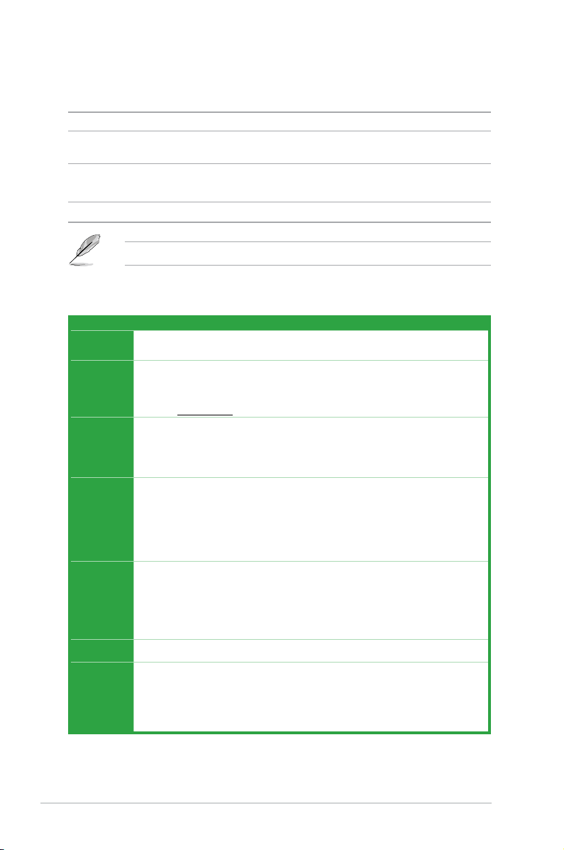
N3050T specications summary
Specications
CPU
Memory
Expansion
slots
Graphics
Storage
LAN
USB
Intel® Celeron® Dual-Core N3050 SoC onboard processor
2 x SO-DIMM DDR3 1600/1066 MHz, maximum 8 GB, non-ECC, un-buffered memory
support both 1.35V DDR3L and 1.5V DDR3
Dual-channel memory architecture
*** Refer to www.asus.com for the Memory QVL (Qualied Vendors List).
1 x mini PCIe (full length, with mSATA support)
1 x mini PCIe (half length)
* mSATA shares the same slot with the full-length mini-PCIe card. mSATA shares the same
bandwidth with SATA6G_2 slot. When a device is installed on the SATA6G_2 slot, the
mSATA device is disabled.
Integrated graphics processor - Intel
Multi-VGA output support: HDMI, D-Sub, LVDS
- Supports HDMI with maximum resolution of 3840 x 2160 @ 30Hz
- Supports D-Sub with maximum resolution of 1920 x 1200 @ 60Hz
- Supports LVDS with maximum resolution of 1920 x 1200 @ 60Hz
Maximum shared memory of 512 MB
®
Intel
Celeron® Dual-Core N3050 SoC onboard Processor
- 1 x mSATA connector
*
- 2 x SATA 6.0 Gb/s connectors
* mSATA shares the same slot with the full-length mini-PCIe card. mSATA shares the same
bandwidth with SATA6G_2 slot. When a device is installed on the SATA6G_2 slot, the
mSATA device is disabled.
®
RTL8111H, 1 x Gigabit LAN Controller
Realtek
®
Intel
Celeron® Dual-Core N3050 SoC onboard Processor
- 4 x USB 3.0 / 2.0 ports (4 ports at the rear panel)
GL852G USB Hub
- 5 x USB 2.0 ports (5 ports at mid-board)
®
HD Graphics support
*
(continued on the next page)
vi

N3050T specications summary
Specications
Audio
ASUS unique
features
Rear panel
I/O ports
Internal
connectors
®
ALC887-VD2 8-channel High Denition Audio CODEC
Realtek
- Supports jack-detection, and front panel jack-retasking
Proven Quality
ASUS 5X PROTECTION
- ASUS LANGuard - Advanced LAN protection
- ASUS Enhanced DRAM Overcurrent Protection - Short circuit damage
prevention
- ASUS ESD Guards - Enhanced ESD protection
- ASUS High-Quality 5K-Hour Solid Capacitors - 2.5x long lifespan with
excellent durability
- ASUS Stainless Steel Back I/O - 3x more durable corrosion-resistant coating
ASUS Exclusive Features
- ASUS AI Charger
- ASUS AI Suite 3
- ASUS USB3.0 Boost
ASUS Quiet Thermal Solution
- ASUS Fan Xpert
One Stop Control
AI Suite 3
Push Notice
- Monitor your PC status with smart devices in real time
Mobo Connect
Media Streamer
- Pipe music or movies from your PC to a smart TV
- Media Streamer app for portable smartphone/tablet, supporting iOS7 and
Android 4.0 system
100% All High-quality Conductive Polymer Capacitors
1 x DC power connector
1 x HDMI port
1 x D-Sub port
4 x USB 3.0/2.0 ports
1 x Gigabit LAN (RJ-45) port
2 x Audio jacks
* Connector Dimension: 7.4 x 5.1mm, Supports both 19V and 12V DC input.
3 x USB 2.0 connectors support additional 5 USB 2.0 ports
2 x SATA 6.0Gb/s connectors
1 x mSATA connector
1 x CPU Fan connector (4pin)
1 x Chassis Fan connector (4pin)
1 x Speaker header (4-1 pin)
*
(continued on the next page)
vii

N3050T specications summary
Specications
1 x Front panel audio connector
1 x TPM connector (14-1 pin)
1 x LVDS connector (40pin)
1 x System Panel connector
1 x Chassis intrusion connector
1 x COM header
1 x Clear CMOS header
Internal
connectors
BIOS features
Connectors for AIO System
1 x 2-pin internal DC power connector
1 x SATA power connector
1 x Stereo speaker connector
1 x DMIC header
Connectors for Flat Panel Display
1 x Display panel backlight power selector
1 x Flat panel display brightness connector
1 x Display panel VCC power selector
1 x LCD panel monitor switch header
64 Mb Flash ROM, UEFI AMI BIOS, PnP, DMI2.0, WfM2.0, SM BIOS 2.8,
ACPI 5.0, Multi-language BIOS, ASUS EZ Flash 3, ASUS CrashFree BIOS3,
My Favorites, Quick Note, Last Modied Log, F12 PrintScreen, F3 Shortcut
functions and ASUS DRAM SPD (Serial Presence Detect) memory information
viii
Manageability
WfM 2.0, DMI 2.0, WOL by PME, PXE
Drivers
Support DVD
ASUS utilities
EZ Update
Anti-virus software (OEM version)
®
10 (64-bit)
Windows
®
8.1 (64-bit)
OS support
Form factor
Windows
®
7 (64-bit)
Windows
Thin Mini-ITX Form Factor, 6.7 in x 6.7 in ( 17.0 cm x 17.0 cm )
Specications are subject to change without notice.
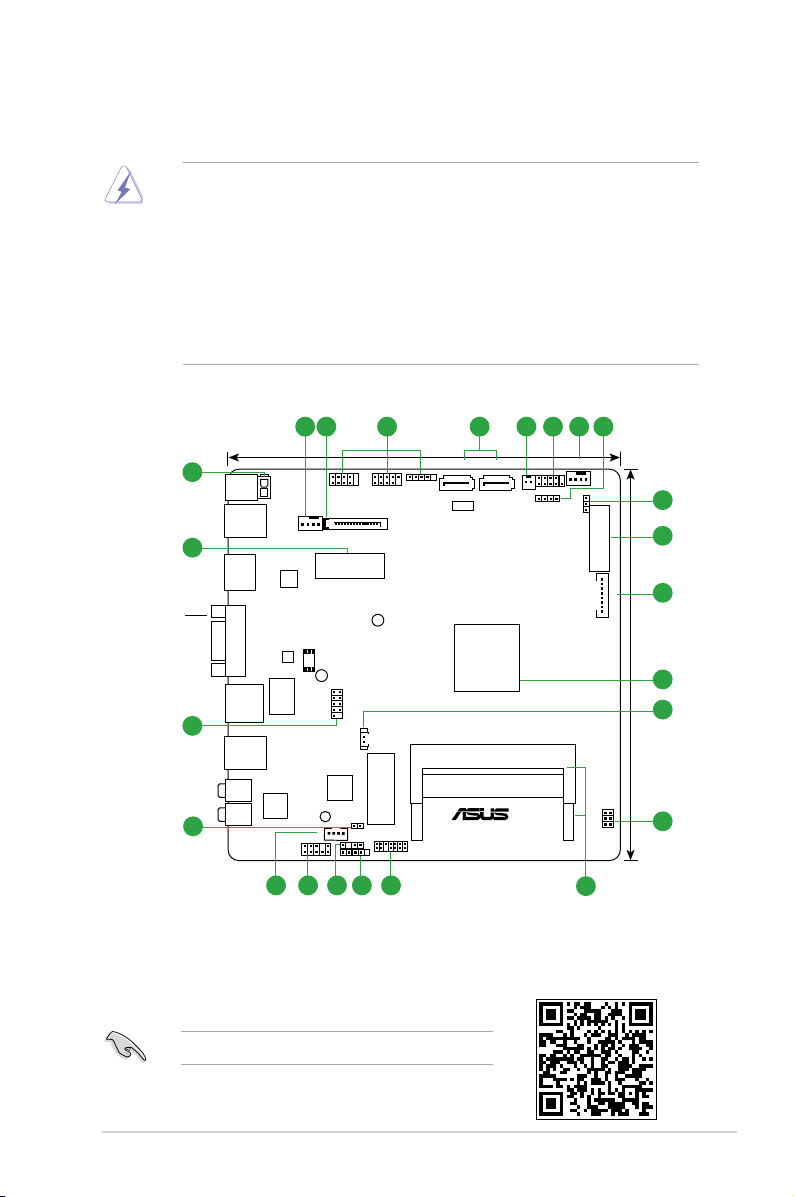
Product introduction
Motherboard overview
Place this
side towards
the rear of the
chassis
• Unplug the power cord from the wall socket before touching any component.
1
• Before handling components, use a grounded wrist strap or touch a safely grounded
object or a metal object, such as the power supply case, to avoid damaging them due
to static electricity.
• Before you install or remove any component, ensure that the ATX power supply is
switched off or the power cord is detached from the power supply. Failure to do so
may cause severe damage to the motherboard, peripherals, or components.
• Unplug the power cord before installing or removing the motherboard. Failure to do so
can cause you physical injury and damage to motherboard components.
1 2 3
23
DC_PWR
ATX19V
USB3_12
22
HDMI
VGA
LAN1
CPU_FAN
ASM
1442K
RTL
8111H
LANGuard
USBE12 USBE34
SATA_PWRCON
MSATA_MPCIE
64Mb
BIOS
21
USB3_34
LINE_OUT
887VD2
MIC IN
20
19
Super
ALC
I/O
SPK_OUT
AAFP
1718
COM4
CLRTC
CHASSIS
16
17.0cm(6.7in)
USBE5
BATT_CON
DDR3 DIMM_B1 (64bit, 204-pin module)
DDR3 DIMM_A1 (64bit, 204-pin module)
WLAN
TPM
DMIC
15
ASM
1480
N3050T
SATA6G_1SATA6G_2
Intel
N3050
PANEL_SW
®
5 6 1 74
F_PANEL
SPEAKER
CHA_FAN
BLKT_PWR_SEL
8
9
LVDS
10
LCD_BLKT_PANEL
17.0cm(6.7in)
11
12
13
VCC_PWR_SEL
14
Scan the QR code to get the detailed pin denitions.
ASUS N3050T
1-1
 Loading...