


ROG
MAXIMUS XI
HERO
(WI-FI)
BIOS Manual
Motherboard

E14964
First Edition
November 2018
Copyright© 2018 ASUSTeK COMPUTER INC. All Rights Reserved.
No part of this manual, including the products and software described in it, may be reproduced,
transmitted, transcribed, stored in a retrieval system, or translated into any language in any form or by any
means, except documentation kept by the purchaser for backup purposes, without the express written
permission of ASUSTeK COMPUTER INC. (“ASUS”).
Product warranty or service will not be extended if: (1) the product is repaired, modied or altered, unless
such repair, modication of alteration is authorized in writing by ASUS; or (2) the serial number of the
product is defaced or missing.
ASUS PROVIDES THIS MANUAL “AS IS” WITHOUT WARRANTY OF ANY KIND, EITHER EXPRESS
OR IMPLIED, INCLUDING BUT NOT LIMITED TO THE IMPLIED WARRANTIES OR CONDITIONS OF
MERCHANTABILITY OR FITNESS FOR A PARTICULAR PURPOSE. IN NO EVENT SHALL ASUS, ITS
DIRECTORS, OFFICERS, EMPLOYEES OR AGENTS BE LIABLE FOR ANY INDIRECT, SPECIAL,
INCIDENTAL, OR CONSEQUENTIAL DAMAGES (INCLUDING DAMAGES FOR LOSS OF PROFITS,
LOSS OF BUSINESS, LOSS OF USE OR DATA, INTERRUPTION OF BUSINESS AND THE LIKE),
EVEN IF ASUS HAS BEEN ADVISED OF THE POSSIBILITY OF SUCH DAMAGES ARISING FROM ANY
DEFECT OR ERROR IN THIS MANUAL OR PRODUCT.
SPECIFICATIONS AND INFORMATION CONTAINED IN THIS MANUAL ARE FURNISHED FOR
INFORMATIONAL USE ONLY, AND ARE SUBJECT TO CHANGE AT ANY TIME WITHOUT NOTICE,
AND SHOULD NOT BE CONSTRUED AS A COMMITMENT BY ASUS. ASUS ASSUMES NO
RESPONSIBILITY OR LIABILITY FOR ANY ERRORS OR INACCURACIES THAT MAY APPEAR IN THIS
MANUAL, INCLUDING THE PRODUCTS AND SOFTWARE DESCRIBED IN IT.
Products and corporate names appearing in this manual may or may not be registered trademarks or
copyrights of their respective companies, and are used only for identication or explanation and to the
owners’ benet, without intent to infringe.
Offer to Provide Source Code of Certain Software
This product contains copyrighted software that is licensed under the General Public License (“GPL”),
under the Lesser General Public License Version (“LGPL”) and/or other Free Open Source Software
Licenses. Such software in this product is distributed without any warranty to the extent permitted by the
applicable law. Copies of these licenses are included in this product.
Where the applicable license entitles you to the source code of such software and/or other additional data,
you may obtain it for a period of three years after our last shipment of the product, either
(1) for free by downloading it from https://www.asus.com/support/
or
(2) for the cost of reproduction and shipment, which is dependent on the preferred carrier and the location
where you want to have it shipped to, by sending a request to:
ASUSTeK Computer Inc.
Legal Compliance Dept.
15 Li Te Rd.,
Beitou, Taipei 112
Taiwan
In your request please provide the name, model number and version, as stated in the About Box of the
product for which you wish to obtain the corresponding source code and your contact details so that we
can coordinate the terms and cost of shipment with you.
The source code will be distributed WITHOUT ANY WARRANTY and licensed under the same license as
the corresponding binary/object code.
This offer is valid to anyone in receipt of this information.
ASUSTeK is eager to duly provide complete source code as required under various Free Open Source
Software licenses. If however you encounter any problems in obtaining the full corresponding source
code we would be much obliged if you give us a notication to the email address gpl@asus.com, stating
the product and describing the problem (please DO NOT send large attachments such as source code
archives, etc. to this email address).
2
ROG MAXIMUS XI HERO (WI-FI) BIOS Manual

Contents
1.1 Knowing BIOS ............................................................................................... 5
1.2 BIOS setup program ..................................................................................... 6
1.2.1 Advanced Mode ............................................................................. 7
1.2.2 EZ Mode....................................................................................... 11
1.2.3 Q-Fan Control .............................................................................. 12
1.2.4 AI OC Guide ................................................................................. 14
1.2.5 EZ Tuning Wizard ........................................................................ 15
1.3 My Favorites ................................................................................................ 17
1.4 Main menu ................................................................................................... 19
1.5 Extreme Tweaker menu .............................................................................. 21
1.6 Advanced menu .......................................................................................... 42
1.6.1 Platform Misc Conguration ......................................................... 43
1.6.2 CPU Conguration ....................................................................... 44
1.6.3 System Agent (SA) Conguration ................................................ 47
1.6.4 PCH Conguration ....................................................................... 48
1.6.5 PCH Storage Conguration.......................................................... 49
1.6.6 PCH-FW Conguration ................................................................ 50
1.6.7 Onboard Devices Conguration ................................................... 51
1.6.8 APM Conguration ....................................................................... 53
1.6.9 PCI Subsystem Settings .............................................................. 53
1.6.10 USB Conguration ....................................................................... 54
1.6.11 Network Stack Conguration........................................................ 55
1.6.12 NVMe Conguration ..................................................................... 55
1.6.13 HDD/SSD SMART Information .................................................... 56
1.7 Monitor menu .............................................................................................. 57
1.8 Boot menu ................................................................................................... 65
1.9 Tool menu .................................................................................................... 70
1.9.1 ASUS EZ Flash 3 Utility ............................................................... 70
1.9.2 Secure Erase ............................................................................... 71
1.9.3 ASUS User Prole........................................................................ 72
1.9.4 ROG OC Panel H-Key Congure ................................................. 73
1.9.5 ASUS SPD Information ................................................................ 74
1.9.6 ASUS Armoury Crate ................................................................... 74
1.9.7 Graphics Card Information ........................................................... 75
ROG MAXIMUS XI HERO (WI-FI) BIOS Manual
3

1.10 Exit menu ..................................................................................................... 76
1.11 Updating BIOS ............................................................................................. 77
1.11.1 EZ Update .................................................................................... 77
1.11.2 ASUS EZ Flash 3 ......................................................................... 78
1.11.3 ASUS CrashFree BIOS 3 ............................................................. 80
4
ROG MAXIMUS XI HERO (WI-FI) BIOS Manual

BIOS Setup
1.1 Knowing BIOS
The new ASUS UEFI BIOS is a Unied Extensible Interface that complies with UEFI
architecture, offering a user-friendly interface that goes beyond the traditional keyboard-
only BIOS controls to enable a more exible and convenient mouse input. You can easily
navigate the new UEFI BIOS with the same smoothness as your operating system. The
term “BIOS” in this user manual refers to “UEFI BIOS” unless otherwise specied.
BIOS (Basic Input and Output System) stores system hardware settings such as storage
device conguration, overclocking settings, advanced power management, and boot
device conguration that are needed for system startup in the motherboard CMOS. In
normal circumstances, the default BIOS settings apply to most conditions to ensure
optimal performance. DO NOT change the default BIOS settings except in the following
circumstances:
• An error message appears on the screen during the system bootup and requests you
to run the BIOS Setup.
• You have installed a new system component that requires further BIOS settings or
update.
Inappropriate BIOS settings may result to instability or boot failure. We strongly
recommend that you change the BIOS settings only with the help of a trained service
personnel.
• When downloading or updating the BIOS le, rename it as M11HW.CAP for this
motherboard.
• BIOS settings and options may vary due to different BIOS release versions. Please
refer to the latest BIOS version for settings and options.
ROG MAXIMUS XI HERO (WI-FI) BIOS Manual
5

1.2 BIOS setup program
Use the BIOS Setup to update the BIOS or congure its parameters. The BIOS screen
include navigation keys and brief onscreen help to guide you in using the BIOS Setup
program.
Entering BIOS at startup
To enter BIOS Setup at startup, press <Delete> or <F2> during the Power-On Self Test
(POST). If you do not press <Delete> or <F2>, POST continues with its routines.
Entering BIOS Setup after POST
To enter BIOS Setup after POST:
• Press <Ctrl>+<Alt>+<Delete> simultaneously.
• Press the reset button on the system chassis.
• Press the power button to turn the system off then back on. Do this option only if you
failed to enter BIOS Setup using the rst two options.
After doing either of the three options, press <Delete> key to enter BIOS.
• The BIOS setup screens shown in this section are for reference purposes only, and
may not exactly match what you see on your screen.
• Ensure that a USB mouse is connected to your motherboard if you want to use the
mouse to control the BIOS setup program.
• If the system becomes unstable after changing any BIOS setting, load the default
settings to ensure system compatibility and stability. Select the Load Optimized
Defaults item under the Exit menu or press hotkey <F5>. See section 1.10 Exit
menu for details.
• If the system fails to boot after changing any BIOS setting, try to clear the CMOS and
reset the motherboard to the default value. See section 2.3.1 Rear I/O connection in
your user manual for the location of the Clear CMOS button to clear RTC RAM.
• The BIOS setup program does not support Bluetooth devices.
BIOS menu screen
The BIOS Setup program can be used under two modes: EZ Mode and Advanced Mode.
You can change modes from Setup Mode in Boot menu or by pressing the <F7> hotkey.
6
ROG MAXIMUS XI HERO (WI-FI) BIOS Manual
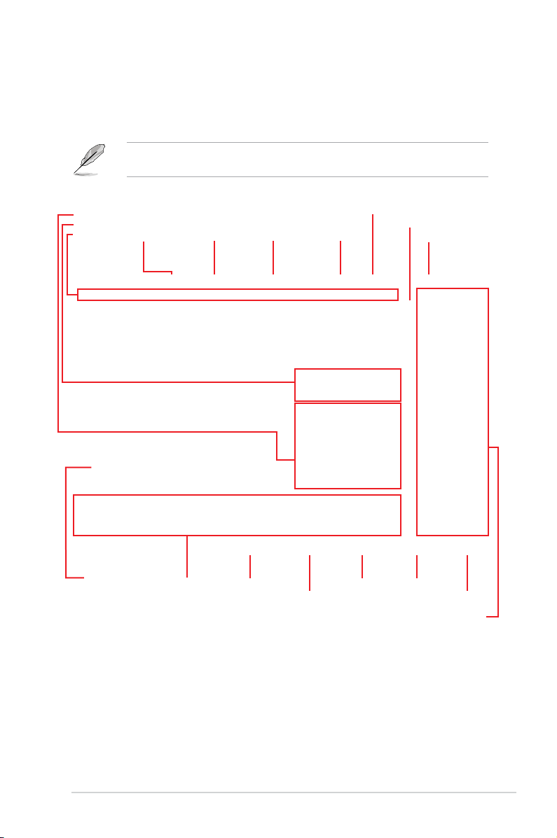
1.2.1 Advanced Mode
The Advanced Mode provides advanced options for experienced end-users to congure
the BIOS settings. The gure below shows an example of the Advanced Mode. Refer to the
following sections for the detailed congurations.
The default screen for entering the BIOS setup program can be changed. Refer to the
Setup Mode item in section Boot menu for details.
Configuration fields
Pop-up Menu
Menu bar
Language Q-Fan Control(F6) AI OC Guide(F11)
Menu items
Search(F9)
MyFavorite(F3) AURA ON/OFF(F4)
General help
Last modified settings
EZ Tuning Wizard
Go back to EZ Mode
Scroll bar
Hot Keys
Search on the FAQ
Displays a quick overview of the
system status and prediction
ROG MAXIMUS XI HERO (WI-FI) BIOS Manual
7

Menu bar
The menu bar on top of the screen has the following main items:
My Favorites
Main
Extreme Tweaker
Advanced
Monitor
Boot
Tool
Exit
For saving the frequently-used system settings and conguration.
For changing the basic system conguration
For changing the overclocking settings
For changing the advanced system settings
For displaying the system temperature, power status, and changing
the fan settings.
For changing the system boot conguration
For conguring options for special functions
For selecting the exit options and loading default settings
Menu items
The highlighted item on the menu bar displays the specic items for that menu. For example,
selecting Main shows the Main menu items.
The other items (My Favorites, Extreme Tweaker, Advanced, Monitor, Boot, Tool, and Exit)
on the menu bar have their respective menu items.
Submenu items
A greater than sign (>) before each item on any menu screen means that the item has a
submenu. To display the submenu, select the item and press <Enter>.
Language
This button above the menu bar contains the languages that you can select for your BIOS.
Click this button to select the language that you want to display in your BIOS screen.
My Favorites(F3)
This button above the menu bar shows all BIOS items in a Tree Map setup. Select frequentlyused BIOS settings and save it to MyFavorites menu.
Refer to section 1.3 My Favorites for more information.
Q-Fan Control(F6)
This button above the menu bar displays the current settings of your fans. Use this button to
manually tweak the fans to your desired settings.
Refer to section 1.2.3 Q-Fan Control for more information.
8
ROG MAXIMUS XI HERO (WI-FI) BIOS Manual

AI OC Guide(F11)
This button above the menu bar allows you to view the descriptions of AI overclocking and
enable it.
• Refer to section 1.2.4 AI OC Guide for more information.
• This function is only enabled when using an unlocked CPU.
Search (F9)
This button allows you to search for BIOS items by entering its name, enter the item name to
nd the related item listing.
AURA (F4)
This button allows you to turn the RGB LED lighting or functional LED on or off.
[All On]: All LEDs (Aura or Functional) will be enabled.
[Aura Only]: Aura LEDs will be enabled and functional LEDs will be disabled.
[Aura Off]: Aura LEDs will be disabled, however functional LEDs will still be enabled.
[Stealth Mode]: All LEDs (Aura and Functional) will be disabled.
Search on FAQ
Move your mouse over this button to show a QR code, scan this QR code on your mobile
device to connect to the BIOS FAQ web page of the ASUS support website. You can also
scan the following QR code:
Scroll bar
A scroll bar appears on the right side of a menu screen when there are items that do not t
on the screen. Press the Up/Down arrow keys or <Page Up> / <Page Down> keys to display
the other items on the screen.
ROG MAXIMUS XI HERO (WI-FI) BIOS Manual
9

General help
At the bottom of the menu screen is a brief description of the selected item. Use <F12> key
to capture the BIOS screen and save it to the removable storage device.
Conguration elds
These elds show the values for the menu items. If an item is user-congurable, you can
change the value of the eld opposite the item. You cannot select an item that is not usercongurable.
A congurable eld is highlighted when selected. To change the value of a eld, select it and
press <Enter> to display a list of options.
Hot keys
This button contains the navigation keys for the BIOS setup program. Use the navigation
keys to select items in the menu and change the settings.
EZ Tuning Wizard
This button above the menu bar allows you to view and congure the RAID settings of your
system.
Refer to section 1.2.5 EZ Tuning Wizard for more information.
Last Modified button
This button shows the items that you last modied and saved in BIOS Setup.
10
ROG MAXIMUS XI HERO (WI-FI) BIOS Manual
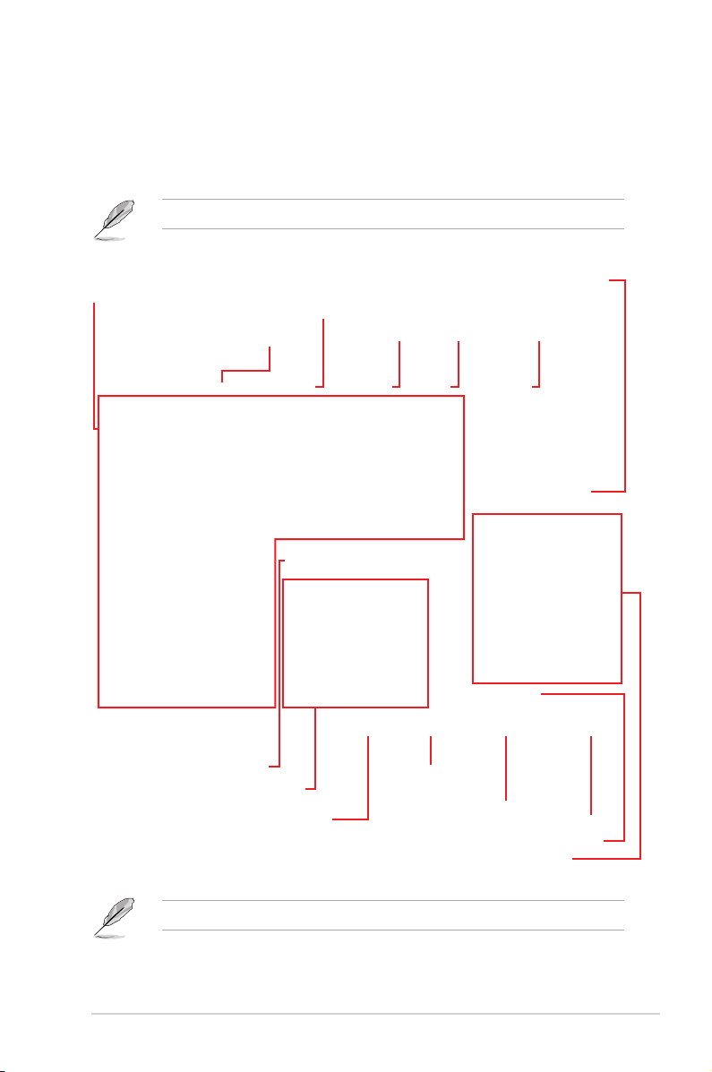
1.2.2 EZ Mode
The EZ Mode provides you an overview of the basic system information, and allows you to
select the display language, system performance, mode and boot device priority. To access
the Advanced Mode, select Advanced Mode or press the <F7> hotkey for the advanced
BIOS settings.
To switch from Advanced Mode to EZ Mode, click EZ Mode(F7) or press the <F7> hotkey.
Displays a quick overview
of the system status
Selects the display language
of the BIOS setup program
Enables or disables the SATA RAID mode
for Intel Rapid Storage Technology
Displays the CPU Fan’s speed. Click
the button to manually tune the fans
Loads optimized
default settings
EZ Tuning Wizard
Displays the system properties of the selected mode.
Saves the changes
and resets the system
Click to go to Advanced mode
Click < or > to switch modes
Search(F9)AI OC Guide(F11)
Selects the boot device priority
AURA ON/OFF(F4)
Search on the FAQ
Click to display boot devices
The boot device options vary depending on the devices you installed to the system.
ROG MAXIMUS XI HERO (WI-FI) BIOS Manual
11

1.2.3 Q-Fan Control
The Q-Fan Control allows you to set a fan prole or manually congure the operating speed
of your CPU and chassis fans.
Click to select a fan to be
configured
Select a profile to
apply to your fans
Click to activate
Click to apply the fan setting
Click to undo the
changes
PWM Mode
Click to go back to main menu
Click to activate DC Mode
Select to manually configure
your fans
12
ROG MAXIMUS XI HERO (WI-FI) BIOS Manual

Configuring fans manually
Select Manual from the list of proles to manually congure your fans’ operating speed.
Speed points
Select to manually
configure your fans
To congure your fans:
1. Select the fan that you want to congure and to view its current status.
2. Click and drag the speed points to adjust the fans’ operating speed.
3. Click Apply to save the changes then click Exit (ESC).
ROG MAXIMUS XI HERO (WI-FI) BIOS Manual
13

1.2.4 AI OC Guide
• The screenshot shown in this section is for reference purposes only, and may not
exactly match what you see on your screen.
• This function is only enabled when using an unlocked CPU.
The AI OC Guide allows you to enable the Ai Overclocking feature, or view a quick guide
of the Ai Overclocking feature which highlights the recommended setup procedure and
descriptions of the AI Overclocking.
Clicking on Enable AI will enable AI Overclocking.
Quick guide topics Click to go back
Click to view the
previous topic in the
quick guide
14
Click to view
the next topic in
the quick guide
Click to enable AI
Overclocking
ROG MAXIMUS XI HERO (WI-FI) BIOS Manual
to main menu

1.2.5 EZ Tuning Wizard
EZ Tuning Wizard allows you to easily set RAID in your system using this feature.
Creating RAID
To create RAID:
1. Click EZ Tuning Wizard from the BIOS screen to open EZ Tuning Wizard screen.
2. Click Yes
3. Select the port that you want to set to [RAID] mode, PCIE or SATA, then click Next.
to enable RAID.
• Ensure that your HDDs have no existing RAID volumes.
• Ensure to connect your HDDs to Intel
®
SATA connectors.
ROG MAXIMUS XI HERO (WI-FI) BIOS Manual
15

4. Select the type of storage for your RAID, Easy Backup or Super Speed, then click
Next.
a. For Easy Backup, click Next then select from Easy Backup (RAID 1) or Easy
Backup (RAID 10).
You can only select Easy Backup (RAID 10) if you connect four (4) HDDs.
b. For Super Speed, click Next then select from Super Speed (RAID 0) or Super
Speed (RAID 5).
5. After selecting the type of RAID, click Next then click Yes to continue the RAID setup.
6. After the RAID setup is done, click Yes to exit the setup then click OK to reset your
system.
16
ROG MAXIMUS XI HERO (WI-FI) BIOS Manual

1.3 My Favorites
My Favorites is your personal space where you can easily save and access your favorite
BIOS items.
My Favorites comes with several performance, power saving, and fast boot related items by
default. You can personalize this screen by adding or removing items.
ROG MAXIMUS XI HERO (WI-FI) BIOS Manual
17
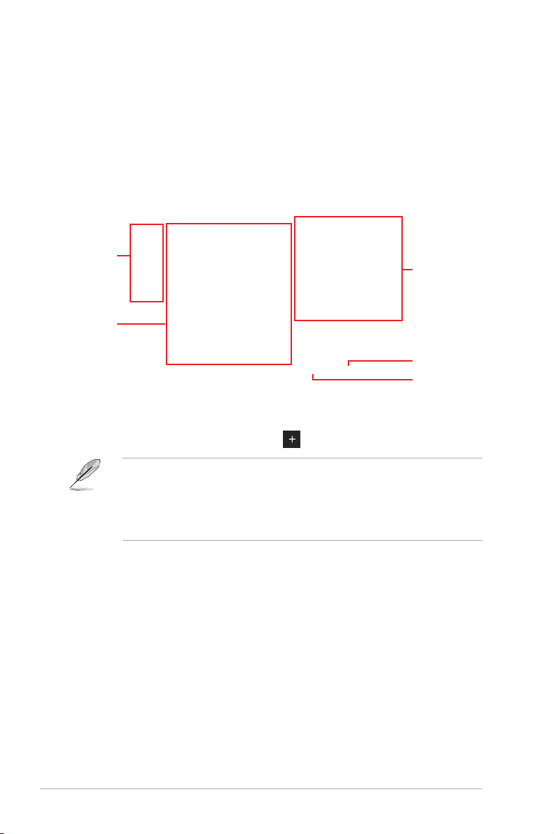
Adding items to My Favorites
To add BIOS items:
1. Press <F3> on your keyboard or click MyFavorites(F3) from the BIOS screen to open
Setup Tree Map screen.
2. On the Setup Tree Map screen, select the BIOS items that you want to save in My
Favorites screen.
Main menu panel
Selected shortcut
items
Submenu panel
Delete all favorite
items
Recover to default
favorite items
3. Select an item from main menu panel, then click the submenu that you want to save as
favorite from the submenu panel and click
You cannot add the following items to My Favorite items:
• Items with submenu options
• User-managed items such as language and boot order
• Conguration items such as Memory SPD Information, system time and date.
or press <Enter> on your keyboard.
4. Click Exit (ESC) or press <Esc> key to close Setup Tree Map screen.
5. Go to My Favorites menu to view the saved BIOS items.
18
ROG MAXIMUS XI HERO (WI-FI) BIOS Manual

1.4 Main menu
The Main menu screen appears when you enter the Advanced Mode of the BIOS Setup
program. The Main menu provides you an overview of the basic system information, and
allows you to set the system date, time, language, and security settings.
Security
The Security menu items allow you to change the system security settings.
• If you have forgotten your BIOS password, erase the CMOS Real Time Clock (RTC)
RAM to clear the BIOS password. See section 2.3.1 Rear I/O connection in your user
manual for the location of the Clear CMOS button to clear RTC RAM.
• The Administrator or User Password items on top of the screen show the default [Not
Installed]. After you set a password, these items show [Installed].
ROG MAXIMUS XI HERO (WI-FI) BIOS Manual
19

Administrator Password
If you have set an administrator password, we recommend that you enter the administrator
password for accessing the system. Otherwise, you might be able to see or change only
selected elds in the BIOS setup program.
To set an administrator password:
1. Select the Administrator Password item and press <Enter>.
2. From the Create New Password box, key in a password, then press <Enter>.
3. Re-type to conrm the password then select OK.
To change an administrator password:
1. Select the Administrator Password item and press <Enter>.
2. From the Enter Current Password box, key in the current password, then press
<Enter>.
3. From the Create New Password box, key in a new password, then press <Enter>.
4. Re-type to conrm the password then select OK.
To clear the administrator password, follow the same steps as in changing an administrator
password, but leave other elds blank then select OK to continue. After you clear the
password, the Administrator Password item on top of the screen shows [Not Installed].
User Password
If you have set a user password, you must enter the user password for accessing the system.
The User Password item on top of the screen shows the default [Not Installed]. After you set
a password, this item shows [Installed].
To set a user password:
1. Select the User Password item and press <Enter>.
2. From the Create New Password box, key in a password, then press <Enter>.
3. Re-type to conrm the password then select OK.
To change a user password:
1. Select the User Password item and press <Enter>.
2. From the Enter Current Password box, key in the current password, then press
<Enter>.
3. From the Create New Password box, key in a new password, then press <Enter>.
4. Re-type to conrm the password then select OK.
To clear the user password, follow the same steps as in changing a user password, but
leave other elds blank then select OK to continue. After you clear the password, the User
Password item on top of the screen shows [Not Installed].
20
ROG MAXIMUS XI HERO (WI-FI) BIOS Manual

1.5 Extreme Tweaker menu
The Extreme Tweaker menu items allow you to congure overclocking-related items.
Be cautious when changing the settings of the Extreme Tweaker menu items. Incorrect
eld values can cause the system to malfunction.
The conguration options for this section vary depending on the CPU and DIMM model you
installed on the motherboard.
Scroll down to display other BIOS items.
Overclocking Presets
Select this item to load various settings suitably tuned for your needs.
Ai Overclock Tuner
This item allows you to select the CPU overclocking options to achieve the desired CPU
internal frequency. Select any of these preset overclocking conguration options:
[Auto] Loads the optimal settings for the system.
[Manual] When the manual mode is selected, the BCLK (base clock) frequency can
[XMP I] If you install memory modules supporting the eXtreme Memory Prole
[XMP II] If you install memory modules supporting the eXtreme Memory Prole
be assigned manually.
(XMP) Technology, choose this item to load the DIMM’s default XMP
memory timings (CL, TRCD, TRP, TRAS) with BCLK frequency and other
memory parameters optimized by ASUS.
(XMP) Technology, choose this item to load the DIMM’s default XMP
prole.
The [X.M.P.] conguration option appears only when you install memory modules
supporting the eXtreme Memory Prole(X.M.P.) Technology.
ROG MAXIMUS XI HERO (WI-FI) BIOS Manual
21

The following item appears only when you set the Ai Overclock Tuner to [XMP I] or
[XMP II].
XMP
This item allows you to select your eXtreme Memory Prole (XMP). Each prole has its
own DRAM frequency, timing and voltage.
The following item appears only when you set the Ai Overclock Tuner to [XMP I],
[XMP II], or [Manual].
BCLK Frequency
This item allows you to set the BCLK (base clock) frequency to enhance the system
performance. Use the <+> or <-> to adjust the value.
We recommend you to set the value based on the CPU specication, as high BCLK
frequencies may damage the CPU permanently.
ASUS MultiCore Enhancement
[Auto] This item allows you to use ASUS optimized core ratio Turbo settings at
[Disabled] This item allows you to use Intel default Turbo core ratio settings.
[Enabled] This item allows you to use optimized power and current thresholds for
default processor speeds.
maintaining maximum performance.
SVID Behavior
This item allows you to program the CPU’s SVID behavior based on the CPU’s quality.
Conguration options: [Auto] [Best-Case Scenario] [Typical Scenario] [Worst-Case Scenario]
[Intel’s Fail Safe]
AVX Instruction Core Ratio Negative Offset
This item allows you to subtract a value from your core ratio at which AVX applications run.
Conguration options: [Auto] [1] – [31]
CPU Core Ratio
This item allows you to set the CPU core ratios.
Conguration options: [Auto] [Sync All Cores] [Per Core] [AI Optimized]
The [AI Optimized] item appears only when you use an unlocked CPU.
22
ROG MAXIMUS XI HERO (WI-FI) BIOS Manual

When the CPU Core Ratio is set to [Sync All Cores] or [Per Core], the following item
appears.
1-Core Ratio Limit
Enter [Auto] to apply the CPU default Turbo Ratio setting or manually
assign a 1-Core Limit value that must be higher than or equal to the 2-Core
Ratio Limit.
When the CPU Core Ratio is set to [Per Core], the following items appears.
2-Core Ratio Limit
Enter [Auto] to apply the CPU default Turbo Ratio setting or manually
assign a 2-core ratio limit that must be higher than or equal to the 3-core
ratio limit.
If you assign a value for 2-Core Ratio Limit, do not set the 1-Core Ratio Limit to [Auto].
3-Core Ratio Limit
Enter [Auto] to apply the CPU default Turbo Ratio setting or manually
assign a 3-core ratio limit that must be higher than or equal to the 4-core
ratio limit.
If you assign a value for 3-Core Ratio Limit, do not set the 1-Core Ratio Limit and 2-Core
Ratio Limit to [Auto].
4-Core Ratio Limit
Enter [Auto] to apply the CPU default Turbo Ratio setting or manually
assign a 4-core ratio limit that must be higher than or equal to the 5-core
ratio limit.
If you assign a value for 4-Core Ratio Limit, do not set the 1-Core Ratio Limit, 2-Core Ratio
Limit, and 3-Core Ratio Limit to [Auto].
5-Core Ratio Limit
Enter [Auto] to apply the CPU default Turbo Ratio setting or manually
assign a 5-core ratio limit that must be higher than or equal to the 6-core
ratio limit.
If you assign a value for 5-Core Ratio Limit, do not set the 1-Core Ratio Limit, 2-Core Ratio
Limit, 3-Core Ratio Limit, and 4-Core Ratio Limit to [Auto].
6-Core Ratio Limit
Enter [Auto] to apply the CPU default Turbo Ratio setting or manually
assign a 6-core ratio limit that must be lower than or equal to the 5-core
ratio limit.
If you assign a value for 6-Core Ratio Limit, do not set the 1-Core Ratio Limit, 2-Core Ratio
Limit, 3-Core Ratio Limit, 4-Core Ratio Limit, and 5-Core Ratio Limit to [Auto].
ROG MAXIMUS XI HERO (WI-FI) BIOS Manual
23

BCLK Frequency : DRAM Frequency Ratio [Auto]
[Auto] The BCLK frequency to DRAM frequency ratio will be set to the optimized
[100:133] The BCLK frequency to DRAM frequency ratio will be set to 100:133.
[100:100] The BCLK frequency to DRAM frequency ratio will be set to 100:100.
setting.
DRAM Odd Ratio Mode
This item allows you to enable or disable availability of odd DRAM ratios for improved
granularity.
Conguration options: [Enabled] [Disabled]
DRAM Frequency
This item allows you to set the memory operating frequency. The congurable options vary
with the BCLK (base clock) frequency setting. Select the auto mode to apply the optimized
setting.
Conguration options: [Auto] [DDR4-800MHz] - [DDR4-8533MHz]
Xtreme Tweaking
This item may help improve some benchmarks performance.
Conguration options: [Enabled] [Disabled]
CPU SVID Support [Auto]
Disable this item to stop the CPU from communicating with the external voltage regulator.
Conguration options: [Auto] [Disabled] [Enabled]
DRAM Timing Control
The sub-items in this menu allow you to set the DRAM timing control features. Use the
<+> and <-> keys to adjust the value. To restore the default setting, type [Auto] using the
keyboard and press the <Enter> key.
Changing the values in this menu may cause the system to become unstable! If this
happens, revert to the default settings.
Memory Presets
Load settings suitably tuned for different memory modules.
Maximus Tweak
Conguration options: [Auto] [Mode 1] – [Mode 2]
Primary Timings
DRAM CAS# Latency
Conguration options: [Auto] [1] – [31]
DRAM RAS# to CAS# Delay
Conguration options: [Auto] [1] – [31]
24
ROG MAXIMUS XI HERO (WI-FI) BIOS Manual

DRAM RAS# ACT Time
Conguration options: [Auto] [1] – [63]
DRAM Command Rate
Conguration options: [Auto] [1N] [2N] [3N] [N:1]
Secondary Timings
DRAM RAS# to RAS# Delay L
Conguration options: [Auto] [1] – [15]
DRAM RAS# to RAS# Delay S
Conguration options: [Auto] [1] – [15]
DRAM REF Cycle Time
Conguration options: [Auto] [1] – [1023]
DRAM REF Cycle Time 2
Conguration options: [Auto] [1] – [1023]
DRAM REF Cycle Time 4
Conguration options: [Auto] [1] – [1023]
DRAM Refresh Interval
Conguration options: [Auto] [1] – [65535]
DRAM WRITE Recovery Time
Conguration options: [Auto] [1] – [31]
DRAM READ to PRE Time
Conguration options: [Auto] [1] – [15]
DRAM FOUR ACT WIN Time
Conguration options: [Auto] [1] – [63]
DRAM WRITE to READ Delay
Conguration options: [Auto] [1] – [15]
DRAM WRITE to READ Delay L
Conguration options: [Auto] [1] – [15]
DRAM WRITE to READ Delay S
Conguration options: [Auto] [1] – [15]
DRAM CKE Minimum Pulse Width
Conguration options: [Auto] [0] – [15]
DRAM Write Latency
Conguration options: [Auto] [1] – [31]
ROG MAXIMUS XI HERO (WI-FI) BIOS Manual
25

Skew Control
ODT RTT WR (CHA)
Conguration options: [Auto] [0 DRAM CLOCK] [80 DRAM CLOCK] [120
ODT RTT PARK (CHA)
Conguration options: [Auto] [0 DRAM CLOCK] [34 DRAM CLOCK] [40
ODT RTT NOM (CHA)
Conguration options: [Auto] [0 DRAM CLOCK] [34 DRAM CLOCK] [40
ODT RTT WR (CHB)
Conguration options: [Auto] [0 DRAM CLOCK] [80 DRAM CLOCK] [120
ODT RTT PARK (CHB)
Conguration options: [Auto] [0 DRAM CLOCK] [34 DRAM CLOCK] [40
ODT RTT NOM (CHB)
Conguration options: [Auto] [0 DRAM CLOCK] [34 DRAM CLOCK] [40
ODT_READ_DURATION
Conguration options: [Auto] [0] - [7]
ODT_READ_DELAY
Conguration options: [Auto] [0] - [7]
ODT_WRITE_DURATION
Conguration options: [Auto] [0] - [7]
ODT_WRITE_DELAY
Conguration options: [Auto] [0] - [7]
Data Rising Slope
Conguration options: [Auto] [0] - [15]
Data Rising Slope Offset
Conguration options: [Auto] [0] - [1]
Cmd Rising Slope
Conguration options: [Auto] [0] - [15]
DRAM CLOCK] [240 DRAM CLOCK] [255 DRAM
CLOCK]
DRAM CLOCK] [48 DRAM CLOCK] [60 DRAM
CLOCK] [80 DRAM CLOCK] [120 DRAM CLOCK]
[240 DRAM CLOCK]
DRAM CLOCK] [48 DRAM CLOCK] [60 DRAM
CLOCK] [80 DRAM CLOCK] [120 DRAM CLOCK]
[240 DRAM CLOCK]
DRAM CLOCK] [240 DRAM CLOCK] [255 DRAM
CLOCK]
DRAM CLOCK] [48 DRAM CLOCK] [60 DRAM
CLOCK] [80 DRAM CLOCK] [120 DRAM CLOCK]
[240 DRAM CLOCK]
DRAM CLOCK] [48 DRAM CLOCK] [60 DRAM
CLOCK] [80 DRAM CLOCK] [120 DRAM CLOCK]
[240 DRAM CLOCK]
26
ROG MAXIMUS XI HERO (WI-FI) BIOS Manual

Cmd Rising Slope Offset
Conguration options: [Auto] [0] - [1]
Ctl Rising Slope
Conguration options: [Auto] [0] - [15]
Ctl Rising Slope Offset
Conguration options: [Auto] [0] - [1]
Clk Rising Slope
Conguration options: [Auto] [0] - [15]
Clk Rising Slope Offset
Conguration options: [Auto] [0] - [1]
Data Falling Slope
Conguration options: [Auto] [0] - [15]
Data Falling Slope Offset
Conguration options: [Auto] [0] - [1]
Cmd Falling Slope
Conguration options: [Auto] [0] - [15]
Cmd Falling Slope Offset
Conguration options: [Auto] [0] - [1]
Ctl Falling Slope
Conguration options: [Auto] [0] - [15]
Ctl Falling Slope Offset
Conguration options: [Auto] [0] - [1]
Clk Falling Slope
Conguration options: [Auto] [0] - [15]
Clk Falling Slope Offset
Conguration options: [Auto] [0] - [1]
RTL IOL Control
DRAM RTL INIT Value
Conguration options: [Auto] [0] - [127]
DRAM RTL (CHA DIMM0 Rank0)
Conguration options: [Auto] [0] - [127]
DRAM RTL (CHA DIMM0 Rank1)
Conguration options: [Auto] [0] - [127]
DRAM RTL (CHA DIMM1 Rank0)
Conguration options: [Auto] [0] - [127]
DRAM RTL (CHA DIMM1 Rank1)
Conguration options: [Auto] [0] - [127]
ROG MAXIMUS XI HERO (WI-FI) BIOS Manual
27

DRAM RTL (CHB DIMM0 Rank0)
Conguration options: [Auto] [0] - [127]
DRAM RTL (CHB DIMM0 Rank1)
Conguration options: [Auto] [0] - [127]
DRAM RTL (CHB DIMM1 Rank0)
Conguration options: [Auto] [0] - [127]
DRAM RTL (CHB DIMM1 Rank1)
Conguration options: [Auto] [0] - [127]
DRAM IOL (CHA DIMM0 Rank0)
Conguration options: [Auto] [0] - [15]
DRAM IOL (CHA DIMM0 Rank1)
Conguration options: [Auto] [0] - [15]
DRAM IOL (CHA DIMM1 Rank0)
Conguration options: [Auto] [0] - [15]
DRAM IOL (CHA DIMM1 Rank1)
Conguration options: [Auto] [0] - [15]
DRAM IOL (CHB DIMM0 Rank0)
Conguration options: [Auto] [0] - [15]
DRAM IOL (CHB DIMM0 Rank1)
Conguration options: [Auto] [0] - [15]
DRAM IOL (CHB DIMM1 Rank0)
Conguration options: [Auto] [0] - [15]
DRAM IOL (CHB DIMM1 Rank1)
Conguration options: [Auto] [0] - [15]
IO Latency offset
CHA IO_Latency_offset
Conguration options: [Auto] [0] - [127]
CHB IO_Latency_offset
Conguration options: [Auto] [0] - [127]
IO Latency RFR delay
CHA RFR delay
Conguration options: [Auto] [0] - [127]
CHB RFR delay
Conguration options: [Auto] [0] - [127]
28
ROG MAXIMUS XI HERO (WI-FI) BIOS Manual

Memory Training Algorithms
The items in this menu allows you to enable or disable different Memory Training
Algorithms.
Early Command Training
Conguration options: [Auto] [Enabled] [Disabled]
SenseAmp Offset Training
Conguration options: [Enabled] [Disabled]
Early ReadMPR Timing Centering 2D
Conguration options: [Enabled] [Disabled]
Read MPR Timing Training
Conguration options: [Enabled] [Disabled]
Receive Enable Training
Conguration options: [Enabled] [Disabled]
Jedec Write Leveling
Conguration options: [Enabled] [Disabled]
Early Write Timing Centering 2D
Conguration options: [Auto] [Enabled] [Disabled]
Early Read Timing Centering 2D
Conguration options: [Auto] [Enabled] [Disabled]
Write Timing Centering 1D
Conguration options: [Enabled] [Disabled]
Write Voltage Centering 1D
Conguration options: [Auto] [Enabled] [Disabled]
Read Timing Centering 1D
Conguration options: [Auto] [Enabled] [Disabled]
Dimm ODT Training*
Conguration options: [Auto] [Enabled] [Disabled]
The following item appears only when you set the Dimm ODT Training* to [Auto] or
[Enabled].
Mac RTT_WR
Conguration options: [ODT Off] [120 Ohms]
DIMM RON Training*
Conguration options: [Auto] [Enabled] [Disabled]
Write Drive Strength/Equalization 2D*
Conguration options: [Enabled] [Disabled]
Write Slew Rate Training*
Conguration options: [Auto] [Enabled] [Disabled]
ROG MAXIMUS XI HERO (WI-FI) BIOS Manual
29

Read ODT Training*
Conguration options: [Auto] [Enabled] [Disabled]
Read Equalization Training*
Conguration options: [Auto] [Enabled] [Disabled]
Read Amplifier Training*
Conguration options: [Auto] [Enabled] [Disabled]
Write Timing Centering 2D
Conguration options: [Auto] [Enabled] [Disabled]
Read Timing Centering 2D
Conguration options: [Auto] [Enabled] [Disabled]
Command Voltage Centering
Conguration options: [Auto] [Enabled] [Disabled]
Write Voltage Centering 2D
Conguration options: [Auto] [Enabled] [Disabled]
Read Voltage Centering 2D
Conguration options: [Auto] [Enabled] [Disabled]
Late Command Training
Conguration options: [Auto] [Enabled] [Disabled]
Round Trip Latency
Conguration options: [Auto] [Enabled] [Disabled]
Turn Around Timing Training
Conguration options: [Enabled] [Disabled]
Rank Margin Tool
Conguration options: [Enabled] [Disabled]
Memory Test
Conguration options: [Enabled] [Disabled]
DIMM SPD Alias Test
Conguration options: [Auto] [Enabled] [Disabled]
Receive Enable Centering 1D
Conguration options: [Auto] [Enabled] [Disabled]
Retrain Margin Check
Conguration options: [Enabled] [Disabled]
Write Drive Strength Up/Dn independently
Conguration options: [Enabled] [Disabled]
30
ROG MAXIMUS XI HERO (WI-FI) BIOS Manual

Third Timings
tRDRD_sg
Conguration options: [Auto] [0] - [63]
tRDRD_dg
Conguration options: [Auto] [0] - [63]
tRDWR_sg
Conguration options: [Auto] [0] - [63]
tRDWR_dg
Conguration options: [Auto] [0] - [63]
tWRWR_sg
Conguration options: [Auto] [0] - [63]
tWRWR_dg
Conguration options: [Auto] [0] - [63]
tWRRD_sg
Conguration options: [Auto] [0] - [127]
tWRRD_dg
Conguration options: [Auto] [0] - [63]
tRDRD_dr
Conguration options: [Auto] [0] - [63]
tRDRD_dd
Conguration options: [Auto] [0] - [63]
tRDWR_dr
Conguration options: [Auto] [0] - [63]
tRDWR_dd
Conguration options: [Auto] [0] - [63]
tWRWR_dr
Conguration options: [Auto] [0] - [63]
tWRWR_dd
Conguration options: [Auto] [0] - [63]
tWRRD_dr
Conguration options: [Auto] [0] - [63]
tWRRD_dd
Conguration options: [Auto] [0] - [63]
TWRPRE
Conguration options: [Auto] [0] - [127]
TRDPRE
Conguration options: [Auto] [0] - [15]
ROG MAXIMUS XI HERO (WI-FI) BIOS Manual
31

tREFIX9
Conguration options: [Auto] [0] - [127]
OREF_RI
Conguration options: [Auto] [0] – [255]
Misc.
MRC Fast Boot
Allows you to enable, disable or automatically set the MRC fast boot.
Conguration options: [Auto] [Enabled] [Disabled]
DRAM CLK Period
Conguration options: [Auto] [1] – [95]
Memory Scrambler
Set this item to enable or disable memory scrambler support.
Conguration options: [Enabled] [Disabled]
Channel A DIMM Control
Allows you to enable or disable the Channel A DIMM slots.
Conguration options: [Enable Both DIMMS] [Disable DIMM0] [Disable DIMM1]
[Disable Both DIMMS]
Channel B DIMM Control
Allows you to enable or disable the Channel B DIMM slots.
Conguration options: [Enable Both DIMMS] [Disable DIMM0] [Disable DIMM1]
[Disable Both DIMMS]
MCH Full Check
Enable this item to enhance the stability of your system. Disable this item to enhance
the DRAM overclocking capability.
Conguration options: [Auto] [Enabled] [Disabled]
Training Profile
Allows you to select the DIMM training prole.
Conguration options: [Auto] [Standard Prole] [User Prole]
DLLBwEn
Conguration options: [Auto] [1] - [7]
DRAM SPD Write
Conguration options: [Enabled] [Disabled]
XTU Setting
Conguration options: [Auto] [1] - [7]
32
ROG MAXIMUS XI HERO (WI-FI) BIOS Manual

External Digi+ Power Control
CPU Load-line Calibration
Load-line is dened by Intel
working voltage decreases proportionally to CPU loading. Higher load-line calibration
could get higher voltage and good overclocking performance, but increases the CPU
and VRM thermal conditions.
Conguration options [Auto] [Level 1] - [Level 7]
The actual performance boost may vary depending on your CPU specication.
DO NOT remove the thermal module. The thermal conditions should be monitored.
Synch ACDC Loadline with VRM Loadline
Enable this item to allow the VRM Loadline to be adjusted automatically to match the
AC/DC Loadline.
Conguration options: [Enabled] [Disabled]
CPU Current Capability
This item allows you to set the shut off current limit for external voltage regulator. A
higher setting will allow the voltage regulator to supply more current while a lower
setting will cause the voltage regulator to shut off the system when the supplied current
is higher than the set value.
Conguration options: [Auto] [100%] - [170%]
Congure higher values when overclocking or under a high loading for extra power support.
CPU VRM Switching Frequency
This item affects the VRM transient response speed and the component thermal
production. Select [Manual] to congure a higher frequency for a quicker transient
response speed.
Conguration options: [Auto] [Manual]
®
specication and affects CPU power voltage. The CPU
DO NOT remove the thermal module. The thermal conditions should be monitored.
The following item appears only when you set the CPU VRM Switching Frequency to
[Manual].
Fixed CPU VRM Switching Frequency (KHz)
This item allows you to set a higher frequency for a quicker transient
response speed. Use the <+> or <-> to adjust the value.
ROG MAXIMUS XI HERO (WI-FI) BIOS Manual
33

The following item appears only when the CPU VRM Switching Frequency is set to
[Auto].
VRM Spread Spectrum
This item allows to enhance the system stability.
Conguration options: [Auto] [Disabled] [Enabled]
CPU Power Duty Control
CPU power duty control adjusts the duty cycle of each VRM phase based upon current
and/or temperature.
[T. Probe] Select to set the VRM thermal balance mode.
[Extreme] Select to set the VRM current balance mode.
DO NOT remove the thermal module when setting this item to [Extreme]. The thermal
conditions should be monitored.
CPU Power Phase Control
This item allows you to set the power phase control of the CPU.
[Auto] Automatically set the phase control mode.
[Standard] The phase control will be based on the CPU command.
[Extreme] Set to the full phase mode.
DO NOT remove the thermal module when setting this item to [Extreme]. The thermal
conditions should be monitored.
CPU VRM Thermal Control
This item allows you to enable or disable the temperature limit of the CPU VRM.
Conguration options: [Auto] [Disabled] [Enabled]
DRAM Current Capability
This item allows you to set the shut off current limit for external DRAM voltage
regulator. A higher setting will allow the voltage regulator to supply more current while
a lower setting will cause the voltage regulator to shut off the system when the supplied
current is higher than the set value.
Conguration options: [100%] [110%] [120%] [130%]
Congure higher values when overclocking or under a high loading for extra power support.
DRAM Switching Frequency
This item affects the VRM transient response speed and the component thermal
production. Select [Manual] to congure a higher frequency for a quicker transient
response speed.
Conguration options: [Auto] [Manual]
34
ROG MAXIMUS XI HERO (WI-FI) BIOS Manual

The following item appears only when you set the DRAM Switching Frequency to
[Manual].
Fixed DRAM Switching Frequency (KHz)
This item allows you to set a higher frequency for a quicker transient
response speed. Use the <+> or <-> to adjust the value.
Boot Voltages
CPU Core/Cache Boot Voltage
Conguration options: [Auto] [0.600] - [1.700]
DMI Boot Voltage
Conguration options: [Auto] [0.3000] - [1.9000]
Core PLL Boot Voltage
Conguration options: [Auto] [0.70000] - [1.60000]
CPU System Agent Boot Voltage
Conguration options: [Auto] [0.7000] - [1.8000]
CPU VCCIO Boot Voltage
Conguration options: [Auto] [0.9000] - [1.8000]
PLL Termination Boot Voltage
Conguration options: [Auto] [0.36000] - [2.27000]
CPU Standby Boot Voltage
Conguration options: [Auto] [0.800] - [1.800]
Internal CPU Power Management
The subitems in this menu allow you to set the CPU ratio and features.
Intel(R) SpeedStep(tm)
Allows the operating system to dynamically adjust the processor voltage and cores
frequency to decrease the average power consumption and decrease average heat
production.
C
onguration options: [Auto] [Enabled] [Disabled]
Turbo Mode
Allows you to enable your processor cores to run faster than the base operating
frequency when it is below power, current and specication limit.
Conguration options: [Disabled] [Enabled]
ROG MAXIMUS XI HERO (WI-FI) BIOS Manual
35

Turbo Mode Parameters
The following items appear only when you set the Turbo Mode to [Enabled].
Long Duration Package Power Limit
As know as the power limit 1 in Watts. The default value will be the TDP
(thermal design power). The turbo ratio can be maintained for a duration to
exceed the TDP for the maximum system performance.
Conguration options: [Auto] [1] - [4095]
Package Power Time Window
As know as the power limit 1 in seconds. The value indicates the
maintained duration for the turbo ratio to exceed TDP (thermal design
power).
Conguration options: [Auto] [1] - [127]
Short Duration Package Power Limit
Also know as the power limit 2 in Watts. It is the second power limit to
provide a rapid protection when the package power exceed power limit
1. The default setting is 1.25 times the power limit 1. According to Intel,
the platform must be capable of supporting the duration for up to 10 msec
when the turbo ratio exceeds the power limit 2. The ASUS motherboards
can support the duration for a longer time.
Conguration options: [Auto] [1] - [4095]
IA AC Load Line
This item allows you to set the AC loadline dened in 1/100 mOhms. Use the <+> and
<-> keys to adjust the value.
Conguration options: [Auto] [0.01] - [62.49]
IA DC Load Line
This item allows you to set the DC loadline dened in 1/100 mOhms. Use the <+> and
<-> keys to adjust the value.
Conguration options: [Auto] [0.01] - [62.49]
TVB Voltage Optimizations
This item controls thermal based voltage optimizations for processors that implement
the Intel Thermal Velocity Boost (TVB) feature.
Conguration options: [Auto] [Enabled] [Disabled]
36
ROG MAXIMUS XI HERO (WI-FI) BIOS Manual

Tweaker’s Paradise
Realtime Memory Timing
This item allows you to enable or disable realtime memory timing.
Conguration options: [Enabled] [Disabled]
FCLK Frequency for Early Power On
This item allows you to set the FCLK Frequency for Early Power On.
Conguration options: [Auto] [Normal (800 MHz)] [1GHz] [400 MHz]
Initial BCLK Frequency
This item allows you to start overclocking the system from the initial BCLK (base clock)
frequency to the assigned BCLK frequency. Use the <+> or <-> to adjust the value.
BCLK Amplitude
This item allows you to set the magnitude of the base clock driven for the processor.
Conguration options: [Auto] [700mV] [800mV] [900mV] [1000mV]
BCLK Slew Rate
Conguration options: [Auto] [1.5V/ns] [2.5V/ns] [3.5V/ns] [4.5V/ns]
BCLK Spread Spectrum
This item allows you to reduce the EMI. Disable to get more accurate base clocks.
Conguration options: [Auto] [Disabled] [-0.22] [-0.34] [-0.46] [+0.12] [+0.22] [+0.28]
[+0.38] [+0.17]
BCLK Frequency Slew Rate
Conguration options: [Auto] [Disabled] [32us/MHz] [64us/MHz] [128us/MHz]
[512us/MHz]
DRAM VTT Voltage
Conguration options: [Auto] [0.50000] - [1.30000]
VPPDDR Voltage
Conguration options: [Auto] [2.10000] - [3.13500]
DMI Voltage
Conguration options: [Auto] [0.30000] - [1.90000]
Core PLL Voltage
Conguration options: [Auto] [0.70000] - [1.60000]
Internal PLL Voltage
Conguration options: [Auto] [0.900] - [1.845]
GT PLL Voltage
Conguration options: [Auto] [0.900] - [1.845]
Ring PLL Voltage
Conguration options: [Auto] [0.900] - [1.845]
ROG MAXIMUS XI HERO (WI-FI) BIOS Manual
37

System Agent PLL Voltage
Conguration options: [Auto] [0.900] - [1.845]
Memory Controller PLL Voltage
Conguration options: [Auto] [0.900] - [1.845]
PLL Bandwidth
Select Level 6 to Level 8 when overclocking High BCLK or High CPU frequency.
Conguration options: [Auto] [Level 0] - [Level 10]
Eventual DRAM Voltage
Conguration options: [Auto] [1.0000] - [2.0000]
Eventual CPU Standby Voltage
Conguration options: [Auto] [0.800] - [1.800]
Eventual PLL Termination Voltage
Conguration options: [Auto] [0.36000] - [2.27000]
Eventual DMI Voltage
Conguration options: [Auto] [0.30000] - [1.90000]
AI Features
The items in this menu allows you to enable or disable different AI Features.
Package Temperature Threshold
Frequency will adjust to stay below this package temperature threshold when Regulate
Frequency by above threshold is enabled.
Conguration options: [Auto] [30] - [115]
Regulate Frequency by above threshold
Frequency will adjust to stay below the Package Temperature Threshold when this
item is enabled.
Conguration options: [Auto] [Enabled] [Disabled]
Cooler Efficiency Customize
[Keep Training] Continuous evaluations will be performed on Cooler efciency
and updated accordingly.
[Stop Training] Cooler efciency evaluations will stop and current evaluated
efciency will be used.
[User Specify] Manually specify the Cooler efciency and all predictions will be
based off this manual setting.
The following item appears only when you set the Cooler Efficiency Customize to [User
Specify].
Cooler Score
Conguration options: [1] - [250]
38
ROG MAXIMUS XI HERO (WI-FI) BIOS Manual

Recalibrate Cooler
This item allows you to recalibrate your cooler efciency.
Cooler Re-evaluation Algorithm
This item allows you to set how inclined the re-evaluation will update.
Conguration options: [Normal] [More inclined to update] [Very inclined to update]
Optimism Scale
This item allows you to set the optimism of the predictions.
Conguration options: [50] - [150]
[Less inclined to update] [Least inclined to update]
CPU Core/Cache Current Limit Max.
This item allows you to congure a higher current limit to prevent a frequency or power
throttling when overclocking. Use the <+> and <-> keys to adjust the value.
Conguration options: [Auto] [0.00] - [255.75]
Ring Down Bin
This item allows you to enable or disable the Ring Down Bin feature. When enabled, the CPU
will down bin the ring ratio, and the requested maximum ring ratio may not be observed.
Conguration options: [Auto] [Disabled] [Enabled]
Please use caution when disabling this feature. Disabling this feature may result in
overvoltaging the CPU.
Min. CPU Cache Ratio
This item allows you to set the minimum possible CPU cache ratio. Use the <+> and <-> keys
to adjust the value.
Conguration options: [Auto] [8] - [83]
Max. CPU Cache Ratio
This item allows you to set the maximum possible CPU cache ratio. Use the <+> and <->
keys to adjust the value.
Conguration options: [Auto] [8] - [83]
BCLK Aware Adaptive Voltage
When this option is enabled, pcode will be aware of the BCLK frequency when calculating the
CPU V/F curves. This is ideal for BCLK OC to avoid high voltage overrides. Uses OC Mailbox
command 0x15.
Conguration options: [Disabled] [Enabled]
CPU Core/Cache Voltage
Congures the mode of Voltage fed to the cores of the processor.
Conguration options: [Auto] [Manual Mode] [Offset Mode] [Adaptive Mode]
ROG MAXIMUS XI HERO (WI-FI) BIOS Manual
39

The following items appear only when you set the CPU Core/Cache Voltage to [Manual
Mode].
CPU Core Voltage Override
Allows you to congure the CPU Core voltage.
Conguration options: [Auto] [0.600] - [1.700]
The following items appear only when you set the CPU Core/Cache Voltage to [Offset
Mode].
Offset Mode Sign
[+] To offset the voltage by a positive value.
[–] To offset the voltage by a negative value.
CPU Core Voltage Offset
This item allows you to congure the CPU core voltage offset value.
Conguration options: [Auto] [0.005] - [0.635]
The following items appear only when you set the CPU Core/Cache Voltage to [Adaptive
Mode].
Offset Mode Sign
[+] To offset the voltage by a positive value.
[–] To offset the voltage by a negative value.
Additional Turbo Mode CPU Core Voltage
This item allows you to congure the CPU core voltage offset value.
Conguration options: [Auto] [0.250] - [1.920]
CPU Core Offset Voltage
This item allows you to congure the CPU core voltage offset value.
Conguration options: [Auto] [0.001] - [0.999]
DRAM Voltage
Conguration options: [Auto] [1.0000] - [2.0000]
CPU VCCIO Voltage
Conguration options: [Auto] [0.90000] - [1.80000]
CPU System Agent Voltage
Conguration options: [Auto] [0.70000] - [1.80000]
PLL Termination Voltage
Conguration options: [Auto] [0.36000] - [2.27000]
PCH Core Voltage
Conguration options: [Auto] [0.90000] - [1.80000]
CPU Standby Voltage
Conguration options: [Auto] [0.800] - [1.800]
40
ROG MAXIMUS XI HERO (WI-FI) BIOS Manual

DRAM REF Voltage Control
DRAM CTRL REF Voltage on CHA/CHB
Congures the DRAM reference voltage on the control lines. The reference voltage will
be the DRAM voltage times the congured value.
Conguration options: [Auto] [0.39500] - [0.63000]
DRAM DATA REF Voltage on CHA DIMM0 Rank0 BL0-7
Congures the DRAM Data REF Voltage.
Conguration options: [Auto] [0] - [63]
DRAM DATA REF Voltage on CHA DIMM0 Rank1 BL0-7
Congures the DRAM Data REF Voltage.
Conguration options: [Auto] [0] - [63]
DRAM DATA REF Voltage on CHA DIMM1 Rank0 BL0-7
Congures the DRAM Data REF Voltage.
Conguration options: [Auto] [0] - [63]
DRAM DATA REF Voltage on CHA DIMM1 Rank1 BL0-7
Congures the DRAM Data REF Voltage.
Conguration options: [Auto] [0] - [63]
DRAM DATA REF Voltage on CHB DIMM0 Rank0 BL0-7
Congures the DRAM Data REF Voltage.
Conguration options: [Auto] [0] - [63]
DRAM DATA REF Voltage on CHB DIMM0 Rank1 BL0-7
Congures the DRAM Data REF Voltage.
Conguration options: [Auto] [0] - [63]
DRAM DATA REF Voltage on CHB DIMM1 Rank0 BL0-7
Congures the DRAM Data REF Voltage.
Conguration options: [Auto] [0] - [63]
DRAM DATA REF Voltage on CHB DIMM1 Rank1 BL0-7
Congures the DRAM Data REF Voltage.
Conguration options: [Auto] [0] - [63]
ROG MAXIMUS XI HERO (WI-FI) BIOS Manual
41

1.6 Advanced menu
The Advanced menu items allow you to change the settings for the CPU and other system
devices.
Be cautious when changing the settings of the Advanced menu items. Incorrect eld values
can cause the system to malfunction.
42
ROG MAXIMUS XI HERO (WI-FI) BIOS Manual

1.6.1 Platform Misc Configuration
The items in this menu allow you to congure the platform-related features.
PCI Express Native Power Management
This item allows you to enhance the power saving feature of PCI Express and perform ASPM
operations in the operating system.
Conguration options: [Disabled] [Enabled]
The following item appears only when you set the PCI Express Native Power Management
to [Enabled].
Native ASPM
Conguration options: [Auto] [Enabled] [Disabled]
PCH - PCI Express
PCH DMI ASPM
This item allows you to control the Active State Power Management on both NB
(NorthBridge) side and SB (SouthBridge) side of the DMI Link.
Conguration options: [Disabled] [L0s] [L1] [L0sL1] [Auto]
ASPM 0
This item allows you to select the ASPM state for energy-saving conditions.
Conguration options: [Disabled] [L0s] [L1] [L0sL1] [Auto]
L1 Substates
This item allows you to select the PCI Express L1 Substates settings.
Conguration options: [L1.1] [L1.1 & L1.2]
PCI Express Clock Gating
This item allows you to enable or disable PCI Express Clock Gating for each port.
Conguration options: [Disabled] [Enabled]
ROG MAXIMUS XI HERO (WI-FI) BIOS Manual
43

SA - PCI Express
DMI Link ASPM Control
This item allows you to control the Active State Power Management on both CPU and PCH
(platform controller hub) Both DMI link ASPM control items of the CPU and PCH sides must
be enabled for the ASPM to take effect.
Conguration options: [Disabled] [L0s] [L1] [L0sL1]
PEG - ASPM
This item allows you to select the ASPM state for energy-saving conditions, or use the ASUS
optimized energy saving prole.
Conguration options: [Disabled] [Auto] [ASPM L0s] [ASPM L1] [ASPM L0sL1]
1.6.2 CPU Configuration
The items in this menu show the CPU-related information that the BIOS automatically
detects.
The items in this menu may vary based on the CPU installed.
Software Guard Extensions (SGX)
This item allows you to enable or disable Software Guard Extensions (SGX).
Conguration options: [Disabled] [Software Controlled]
Tcc Offset Time Window
This item allows you to set the TCC Offset Time Window for Running Average Temperature
Limit (RATL) feature. RATL allows setting an average max thermal temperature.
Temperatures within the time window can get higher than the temperature threshold but only
the average is used to cause frequency clipping.
Conguration options: [Auto] [Disabled] [5 ms] - [448 sec]
44
ROG MAXIMUS XI HERO (WI-FI) BIOS Manual

Hardware Prefetcher
This item allows the CPU to prefetch commands and data in the L2 cache, reduces the
DRAM loading time and improves the system performance.
Conguration options: [Disabled] [Enabled]
Adjacent Cache Line Prefetch
This item allows you to prefetch adjacent cache lines, reducing the DRAM loading time and
improves the system performance.
Conguration options: [Disabled] [Enabled]
Intel (VMX) Virtualization Technology
When set to [Enabled], VMX can utilize the additional hardware capabilities provided by
Vanderpool Technology.
Conguration options: [Disabled] [Enabled]
Active Processor Cores
This item allows you to select the number of CPU cores to activate in each processor
package.
Conguration options: [All] [1] - [5]
Thermal Monitor
This item allows you to enable or disable the Thermal Monitor.
Conguration options: [Disabled] [Enabled]
CPU Power Management Configuration
This item allows you to manage and congure the CPU’s power.
Boot performance mode
This item allows you to select the CPU performance state during system boot before
the operating system takes control. The CPU runs at a selected performance ratio
based on CPU conguration.
Conguration options: [Auto] [Max Battery] [Max Non-Turbo Performance]
Intel(R) SpeedStep(tm)
This item allows more than two frequency to be supported.
Conguration options: [Auto] [Enabled] [Disabled]
Intel(R) Speed Shift Technology
This item allows you to disable or enable Intel(R) Speed Shift Technology support.
When enabled, CPPC v2 interface allows hardware controlled P-states.
Conguration options: [Auto] [Enabled] [Disabled]
Turbo Mode
This item allows you to automatically set the CPU cores to run faster than the base
operating frequency when it is below the operating power, current and temperature
specication limit.
Conguration options: [Enabled] [Disabled]
[Turbo Performance]
ROG MAXIMUS XI HERO (WI-FI) BIOS Manual
45

CPU C-states
This item allows you to set the power saving of the CPU states.
Conguration options: [Auto] [Disabled] [Enabled]
The following items appear only when you set the CPU C-states to [Enabled].
Enhanced C-States
When enabled, CPU will switch to minimum speed when all cores enter
C-State.
Conguration options: [Enabled] [Disabled]
CPU C3 Report
This item allows you to disable or enable the CPU C3 report to the
operating system.
Conguration options: [Enabled] [Disabled]
CPU C6 Report
This item allows you to disable or enable the CPU C6 report to the
operating system.
Conguration options: [Enabled] [Disabled]
CPU C7 Report
This item allows you to disable or enable the CPU C7 report to the
operating system.
Conguration options: [CPU C7] [CPU C7s] [Disabled]
CPU C8 Report
This item allows you to disable or enable the CPU C8 report to the
operating system.
Conguration options: [Enabled] [Disabled]
CPU C9 Report
This item allows you to disable or enable the CPU C9 report to the
operating system.
Conguration options: [Enabled] [Disabled]
CPU C10 Report
This item allows you to disable or enable the CPU C10 report to the
operating system.
Conguration options: [Enabled] [Disabled]
Package C State Limit
This item allows you to set the C-state limit for the CPU package.
Conguration options: [C0/C1] [C2] [C3] [C6] [C7] [C7s] [C8] [C9] [C10]
[CPU Default] [Auto]
CFG Lock
This item allows you to disable or enable the CFG Lock.
Conguration options: [Enabled] [Disabled]
46
ROG MAXIMUS XI HERO (WI-FI) BIOS Manual

1.6.3 System Agent (SA) Configuration
VT-d
Allows you to enable virtualization technology function on memory control hub.
Conguration options: [Enabled] [Disabled]
Above 4G Decoding
This item enables or disables 64-bit capable devices to be decoded in above 4G address
space if your system supports 64-bit PCI Decoding.
Conguration options: [Enabled] [Disabled]
Memory Configuration
This item allows you to set memory conguration parameters.
Memory Remap
This item allows you to enable or disable memory remap above 4GB.
Conguration options: [Enabled] [Disabled]
Graphics Configuration
This item allows you to select a primary display from CPU and PCIe graphical devices.
Primary Display
This item allows you to select the primary display from CPU and PCIe devices.
Conguration options: [Auto] [CPU Graphics] [PCIE]
iGPU Multi-Monitor
This item allows you to enable the iGPU Multi-Monitor. The iGPU shared system
memory size is xed 64 MB.
Conguration options: [Disabled] [Enabled]
DMI/OPI Configuration
This item allows you to control various DMI (direct media interface) functions.
DMI Max Link Speed
This item allows you to set DMI speed.
Conguration options: [Auto] [Gen1] [Gen2] [Gen3]
ROG MAXIMUS XI HERO (WI-FI) BIOS Manual
47

PEG Port Configuration
This item allows you to congure the PEG Port settings.
PCIEx16_1 Link Speed
This item allows you to congure the PCIEx16_1 slot.
Conguration options: [Auto] [Gen1] [Gen2] [Gen3]
PCIEx16_2 Link Speed
This item allows you to congure the PCIEx16_2 slot.
Conguration options: [Auto] [Gen1] [Gen2] [Gen3]
1.6.4 PCH Configuration
PCI Express Configuration
This item allows you to congure the PCI Express slots.
PCIe Speed
This item allows your system to automatically select the PCI Express port speed.
Conguration options: [Auto] [Gen1] [Gen2] [Gen3]
IOAPIC 24-119 Entires
Allows you to enable or disable IOAPIC 24-119 Entires. Disabling this item may cause some
devices to fail.
Conguration options: [Enabled] [Disabled]
48
ROG MAXIMUS XI HERO (WI-FI) BIOS Manual

1.6.5 PCH Storage Configuration
While entering Setup, the BIOS automatically detects the presence of SATA devices. The
SATA Port items show Empty if no SATA device is installed to the corresponding SATA port.
Scroll down to display the other BIOS items.
SATA Controller(s)
This item allows you to enable or disable the SATA Device.
Conguration options: [Disabled] [Enabled]
The following item appears only when you set the SATA Controller(s) to [Enabled].
SATA Mode Selection
This item allows you to set the SATA conguration.
[AHCI] Set to [AHCI] when you want the SATA hard disk drives to
[Intel RST Premium With
Intel Optane System
Acceleration (RAID)]
ROG MAXIMUS XI HERO (WI-FI) BIOS Manual
use the AHCI (Advanced Host Controller Interface). The AHCI
allows the onboard storage driver to enable advanced Serial
ATA features that increases storage performance on random
workloads by allowing the drive to internally optimize the order
of commands.
Set to [Intel RST Premium With Intel Optane System
Acceleration (RAID)] when you want to create a RAID
conguration from the SATA hard disk drives.
49

Aggressive LPM support
This item is designed for LPM (link power management) support with a better energy saving
conditions. When disabled, the hot plug function of SATA ports are disabled.
Conguration options: [Disabled] [Enabled]
SMART Self Test
S.M.A.R.T. (Self-Monitoring, Analysis and Reporting Technology) is a monitoring system that
shows a warning message during POST (Power-on Self Test) when an error occurs in the
hard disks.
Conguration options: [On] [Off]
SATA6G_1(Black) - SATA6G_6(Black)
SATA6G_1(Black) - SATA6G_6(Black)
This item allows you to enable or disable the selected SATA port.
Conguration options: [Disabled] [Enabled]
SATA6G_1 - SATA6G_6 Hot Plug
These items appears only when the SATA Mode Selection is set to [AHCI] and allows
you to enable or disable SATA Hot Plug Support.
Conguration options: [Disabled] [Enabled]
1.6.6 PCH-FW Configuration
This item allows you to congure the rmware TPM.
TPM Device Selection
This item allows you to select the TPM device.
Conguration options: [Discrete TPM] [Firmware TPM]
50
ROG MAXIMUS XI HERO (WI-FI) BIOS Manual

1.6.7 Onboard Devices Configuration
Scroll down to view the other BIOS items.
HD Audio Controller
This item allows you to use the Azalia High Denition Audio Controller.
Conguration options: [Disabled] [Enabled]
Intel LAN Controller
This item allows you to enable or disable the Intel(R) LAN controller.
Conguration options: [Disabled] [Enabled]
The following item appears only when you set the Intel LAN Controller to [Enabled].
Intel LAN PXE Option ROM
This item allows you to enable or disable the PXE Option Rom of the Intel LAN
controller.
Conguration options: [Disabled] [Enabled]
LED lighting
When system is in working state
This item allows you to turn the RGB LED lighting on or off when the system is in the
working state.
[All On]: All LEDs (Aura or Functional) will be enabled.
[Aura Only]: Aura LEDs will be enabled and functional LEDs will be disabled.
[Aura Off]: Aura LEDs will be disabled, however functional LEDs will still be
[Stealth Mode]: All LEDs (Aura and Functional) will be disabled.
ROG MAXIMUS XI HERO (WI-FI) BIOS Manual
enabled.
51

Q-Code LED Function
[Auto] Automatically display POST (Power-On Self-Test) code and CPU
[POST Code Only] Show POST (Power-On Self-Test) code on Q-Code LED.
When system is in sleep, hibernate or soft off states
This item allows you to turn the RGB LED lighting on or off when the system is in the
sleep, hibernate or soft off states.
[On] LEDs will light up in S3(sleep), S4(hibernate) and S5(soft off)
[Off] LEDs will not light up in S3(sleep), S4(hibernate) and S5(soft off)
temperature on Q-Code LED.
states.
states.
M.2_1 Configuration
[Auto] Auto-detects the M.2 device mode. If a SATA device is detected,
[SATA mode] Only supports M.2 SATA devices. Please note that SATA6G_2 port cannot
[PCIE mode] Only supports M.2 PCIE devices.
SATA6G_2 will be disabled.
be used in this mode.
PCIEX16_3 Bandwidth
[X2] Run at X2 mode with SATA6G_56 enabled.
[X4] Run at X4 mode for higher performance with SATA6G_56 disabled.
Hyper M.2 X16: [Disable][Enable]
[Disabled] Only one SSD installed onto the Hyper M.2 X16 card can be detected.
[Enabled] Two or three SSDs installed onto the Hyper M.2 X16 card can be detected.
When Hyper M.2 X16 is set to [Enabled], only the Hyper M.2 X16 Card will be supported
in this slot.
USB power deliver in Soft Off state (S5)
This item allows you to enable or disable USB power when your PC is in the S5 state.
Conguration options: [Disabled] [Enabled]
Back I/O USB Type C Power Mode
[Auto] The system will automatically detect your USB 3.1 Gen 2 Type-C devices
[Enabled] The USB Type C port will always provide power to your USB 3.1 Gen 2
and provide suitable power if needed.
Type-C devices.
Connectivity mode (Wi-Fi & Bluetooth)
This item allows you to enable or disable the Wi-Fi & Bluetooth connectivity module.
Conguration options: [Disabled] [Enabled]
52
ROG MAXIMUS XI HERO (WI-FI) BIOS Manual

1.6.8 APM Configuration
ErP Ready
This item allows you to switch off some power at S4+S5 or S5 to get the system ready for
ErP requirement. When set to [Enabled], all other PME options are switched off.
Conguration options: [Disabled] [Enabled (S4+S5)] [Enabled (S5)]
Restore AC Power Loss
This item allows your system to go to ON state, OFF state, or both states after an AC power
loss. When setting your system to [Last State], it goes to the previous state before the AC
power loss.
Conguration options: [Power Off] [Power On] [Last State]
Power On By PCI-E
This item allows you to enable or disable the Wake-on-LAN function of the onboard LAN
controller or other installed PCI-E LAN cards.
Conguration options: [Disabled] [Enabled]
Power On By RTC
This item allows you to enable or disable the RTC (Real-Time Clock) to generate a wake
event and congure the RTC alarm date. When enabled, you can set the days, hours,
minutes, or seconds to schedule an RTC alarm date.
Conguration options: [Disabled] [Enabled]
1.6.9 PCI Subsystem Settings
SR-IOV Support
This option enables or disables Single Root IO Virtualization Support if the system has SR-
IOV capable PCIe devices.
Conguration options: [Disabled] [Enabled]
ROG MAXIMUS XI HERO (WI-FI) BIOS Manual
53

1.6.10 USB Configuration
The items in this menu allow you to change the USB-related features.
The Mass Storage Devices item shows the auto-detected values. If no USB device is
detected, the item shows None.
Legacy USB Support
[Enabled] Your system supports the USB devices in legacy operating systems.
[Disabled] Your USB devices can be used for BIOS setup only and cannot be
[Auto] Your system automatically detects the presence of USB devices at startup.
XHCI Hand-off
recognized in the boot devices list.
If any USB devices are detected, the legacy USB support is enabled.
This item is set to [Disabled] by default for the EHCI (enhanced host controller interface)
support by XHCI drivers in operating systems.
[Disabled] Support XHCI by XHCI drivers for operating systems with XHCI support.
[Enabled] Support XHCI by BIOS for operating systems without XHCI support.
USB Port Disable Override
This item allows you to enable or disable the individual USB ports.
Refer to section 1.1.2 Motherboard layout in your user manual for the location of the USB
ports.
54
ROG MAXIMUS XI HERO (WI-FI) BIOS Manual

1.6.11 Network Stack Configuration
Network stack
This item allows you to disable or enable the UEFI network stack.
Conguration options: [Disable] [Enable]
The following item appears only when you set the Network Stack to [Enabled].
Ipv4/Ipv6 PXE Support
This item allows you to enable or disable the Ipv4/Ipv6 PXE wake event.
Conguration options: [Disabled] [Enabled]
1.6.12 NVMe Configuration
This menu displays the NVMe controller and Drive information of the connected devices.
ROG MAXIMUS XI HERO (WI-FI) BIOS Manual
55

1.6.13 HDD/SSD SMART Information
This menu displays the SMART information of the connected devices.
NVM Express devices do not support SMART information.
56
ROG MAXIMUS XI HERO (WI-FI) BIOS Manual

1.7 Monitor menu
The Monitor menu displays the system temperature/power status, and allows you to change
the fan settings.
Scroll down to display the other BIOS items.
CPU Temperature, Motherboard Temperature, PCH temperature, T Sensor
Temperature, Water In T Sensor, Water Out T Sensor, EXT_Sensor1-3
Temperature [xxx°C/xxx°F]
The onboard hardware monitor automatically detects and displays the component and sensor
temperatures. Select [Ignore] if you do not wish to display the detected temperatures.
CPU Fan Speed, CPU Optional Fan Speed, Chassis Fan 1-3 Speed, High Amp
Fan Speed, W_PUMP+ Speed, AIO pump Speed, Extension Fan 1-3, Flow
Rate [xxxx RPM]
The onboard hardware monitor automatically detects and displays the fan and pump speeds
in rotations per minute (RPM). If the fan or pump is not connected to the motherboard, the
eld shows N/A. Select [Ignore] if you do not wish to display the detected speed.
CPU Core Voltage, 3.3V Voltage, 5V Voltage, 12V Voltage [x.xxxx V]
The onboard hardware monitor automatically detects the voltage output through the onboard
voltage regulators. Select [Ignore] if you do not want to detect this item.
ROG MAXIMUS XI HERO (WI-FI) BIOS Manual
57

Q-Fan Configuration
Q-Fan Tuning
Click this item to automatically detect the lowest speed and congure the minimum
duty cycle for each fan.
CPU Q-Fan Control
This item allows you to set the CPU Q-Fan operating mode.
[Auto] Detects the type of CPU fan installed and automatically switches
[PWM Mode] Enables the CPU Q-Fan Control feature in PWM mode for 4-pin
[DC Mode] Enables the CPU Q-Fan Control feature in DC mode for 3-pin CPU
[Disabled] Disables the Q-Fan Control.
The following items appear only when you set the CPU Q-Fan Control to [Auto], [PWM
Mode], or [DC Mode].
CPU Fan Step Up
This item allows you to set the value of the CPU fan step up.
Conguration options: [0 sec] [2.1 sec] [2.8 sec] [3.6 sec] [4.2 sec] [5.0 sec] [6.3 sec]
CPU Fan Step Down
This item allows you to set the value of the CPU fan step down.
Conguration options: [0 sec] [2.1 sec] [2.8 sec] [3.6 sec] [4.2 sec] [5.0 sec] [6.3 sec]
CPU Fan Speed Low Limit
This item allows you to set the low limit warning for CPU Fan speed.
Conguration options: [Ignore] [200 RPM] [300 RPM] [400 RPM] [500 RPM] [600 RPM]
CPU Fan Profile
This item allows you to set the appropriate performance level of the CPU fan.
[Standard] Set to make the CPU fan adjust automatically depending on the CPU
[Silent] Set to minimize the fan speed for quiet CPU fan operation.
[Turbo] Set to achieve maximum CPU fan speed.
[Manual] Set to assign the detailed fan speed control parameters.
the control modes.
CPU fan.
fan.
[8.5 sec] [12 sec] [25 sec]
[8.5 sec] [12 sec] [25 sec]
temperature.
58
ROG MAXIMUS XI HERO (WI-FI) BIOS Manual

Chassis Fan(s) Configuration
Chassis Fan 1-3 Q-Fan Control
This item allows you to set the chassis fan operating mode.
[Auto] Detects the type of chassis fan installed and automatically switches
the control modes.
[PWM Mode] Enables the Chassis Fan Q-Fan Control feature in PWM mode for
4-pin chassis fan.
[DC Mode] Enables the Chassis Fan Q-Fan Control feature in DC mode for
3-pin chassis fan.
[Disabled] Disables the Q-Fan control.
The following items appear only when you set the Chassis Fan 1-3 Q-Fan Control to
[Auto], [PWM Mode], or [DC Mode].
Chassis Fan 1-3 Q-Fan Source
The assigned fan will be controlled according to the selected temperature source.
Conguration options: [CPU] [MotherBoard] [PCH] [T Sensor] [Water In T Sensor]
[Water Out T Sensor] [EXT_Sensor1] [EXT_Sensor2] [EXT_
Sensor3] [Multiple Sources]
• For EXT_Sensor1-3, connect a Thermistor cable to one of these connectors, then
tape the other end on a critical component to control its temperature.
• For Multiple Sources, select up to three temperature sources and the fan will
automatically change based on the highest temperature.
Chassis Fan 1-3 Step Up
This item allows you to set the value of the chassis fan step up.
Conguration options: [0 sec] [12 sec] [25 sec] [51 sec] [76 sec] [102 sec] [127 sec]
[153 sec] [178 sec] [204 sec]
Chassis Fan 1-3 Step Down
This item allows you to set the value of the chassis fan step down.
Conguration options: [0 sec] [12 sec] [25 sec] [51 sec] [76 sec] [102 sec] [127 sec]
[153 sec] [178 sec] [204 sec]
Chassis Fan 1-3 Fan Speed Low Limit
This item allows you to disable or set the chassis fan warning speed.
Conguration options: [Ignore] [200 RPM] [300 RPM] [400 RPM] [500 RPM] [600 RPM]
ROG MAXIMUS XI HERO (WI-FI) BIOS Manual
59

Chassis Fan 1-3 Profile
This item allows you to set the appropriate performance level of the chassis fan.
[Standard] Sets to [Standard] to make the chassis fan automatically adjust
depending on the chassis temperature.
[Silent] Sets to [Silent] to minimize the fan speed for quiet chassis fan
operation.
[Turbo] Sets to [Turbo] to achieve maximum chassis fan speed.
[Manual] Sets to [Manual] to assign detailed fan speed control parameters.
The following items appear only when you set Chassis Fan 1-3 Profile to [Manual].
Chassis Fan 1-3 Upper Temperature
Use the <+> or <-> keys to adjust the upper limit of the Chassis Fan 1-3
temperature. The Chassis Fan 1-3 will operate at the maximum duty cycle
when the temperature source is higher than the limit.
Chassis Fan 1-3 Max. Duty Cycle (%)
Use the <+> or <-> keys to adjust the maximum Chassis Fan 1-3 duty
cycle. When the temperature source reaches the upper limit, the Chassis
Fan 1-3 will operate at the maximum duty cycle.
Chassis Fan 1-3 Middle Temperature
Use the <+> or <-> keys to adjust the middle limit of the Chassis Fan 1-3
temperature.
Chassis Fan 1-3 Middle. Duty Cycle (%)
Use the <+> or <-> keys to adjust the Chassis Fan 1-3 middle duty cycle.
Chassis Fan 1-3 Lower Temperature
Use the <+> or <-> keys to adjust the lower limit of the Chassis Fan 1-3
temperature. The Chassis Fan 1-3 will operate at the minimum duty cycle
when the temperature source is lower than the limit.
Chassis Fan 1-3 Min. Duty Cycle(%)
Use the <+> or <-> keys to adjust the minimum Chassis Fan 1-3 duty cycle.
When the temperature source is under the limit, the Chassis Fan 1-3 will
operate at the minimum duty cycle.
High Amp Fan Control
This item allows you to set the High Amp Fan operating mode.
[Auto] Detects the type of High Amp Fan installed and automatically
switches the control modes.
[PWM Mode] Enables the High Amp Fan Control feature in PWM mode for 4-pin
High Amp Fan.
[DC Mode] Enables the High Amp Fan Control feature in DC mode for 3-pin
High Amp Fan.
[Disabled] Disables the High Amp Fan Control.
60
ROG MAXIMUS XI HERO (WI-FI) BIOS Manual

High Amp Fan Q-Fan Source
The assigned fan will be controlled according to the selected temperature source.
Conguration options: [CPU] [MotherBoard] [PCH] [T Sensor] [Water In T Sensor]
[Water Out T Sensor] [EXT_Sensor1] [EXT_Sensor2]
[EXT_Sensor3] [Multiple Sources]
• For EXT_Sensor1-3, connect a Thermistor cable to one of these connectors, then
tape the other end on a critical component to control its temperature.
• For Multiple Sources, select up to three temperature sources and the fan will
automatically change based on the highest temperature.
High Amp Fan Step Up
This item allows you to set the value of the High Amp fan step up.
Conguration options: [0 sec] [12 sec] [25 sec] [51 sec] [76 sec] [102 sec] [127 sec]
[153 sec] [178 sec] [204 sec]
High Amp Fan Step Down
This item allows you to set the value of the High Amp fan step down.
Conguration options: [0 sec] [12 sec] [25 sec] [51 sec] [76 sec] [102 sec] [127 sec]
[153 sec] [178 sec] [204 sec]
High Amp Fan Speed Low Limit
This item allows you to disable or set the High Amp fan warning speed.
Conguration options: [Ignore] [200 RPM] [300 RPM] [400 RPM] [500 RPM] [600 RPM]
High Amp Fan Profile
This item allows you to set the appropriate performance level of the High Amp Fan.
[Standard] Sets to [Standard] to make the chassis fan automatically adjust
depending on the chassis temperature.
[Silent] Sets to [Silent] to minimize the fan speed for quiet chassis fan
operation.
[Turbo] Sets to [Turbo] to achieve maximum chassis fan speed.
[Manual] Sets to [Manual] to assign detailed fan speed control parameters.
ROG MAXIMUS XI HERO (WI-FI) BIOS Manual
61

The following items appear only when you set High Amp Fan Prole to [Manual].
High Amp Fan Upper Temperature
Use the <+> or <-> keys to adjust the upper limit of the High Amp Fan
temperature. The High Amp Fan will operate at the maximum duty cycle
when the temperature source is higher than the limit.
High Amp Fan Max. Duty Cycle (%)
Use the <+> or <-> keys to adjust the maximum High Amp Fan duty cycle.
When the temperature source reaches the upper limit, the High Amp Fan
will operate at the maximum duty cycle.
High Amp Fan Middle Temperature
Use the <+> or <-> keys to adjust the middle limit of the High Amp Fan
temperature.
High Amp Fan Middle. Duty Cycle (%)
Use the <+> or <-> keys to adjust the High Amp Fan middle duty cycle.
High Amp Fan Lower Temperature
Use the <+> or <-> keys to adjust the lower limit of the High Amp Fan
temperature. The High Amp Fan will operate at the minimum duty cycle
when the temperature source is lower than the limit.
High Amp Fan Min. Duty Cycle (%)
Use the <+> or <-> keys to adjust the minimum High Amp Fan duty cycle.
When the temperature source is under the limit, the High Amp Fan will
operate at the minimum duty cycle.
Ext. Fan(s) Configuration
An ASUS FAN EXTENSION CARD is required to congure these items
Extension Fan 1-3 Q-Fan Control
[Disabled] Disable the Extension Fan Q-Fan control feature.
[DC mode] Enable the Extension Fan Q-Fan control in DC mode for 3-pin
extension fan.
[PWM mode] Enable the Extension Fan Q-Fan control in PWM mode for 4-pin
extension fan.
Extension Fan 1-3 Q-Fan Source
The assigned fan will be controlled according to the selected temperature source.
Conguration options: [CPU] [MotherBoard] [PCH] [T Sensor] [Water In T Sensor]
[Water Out T Sensor] [EXT_Sensor1] [EXT_Sensor2] [EXT_
Sensor3] [Multiple Sources]
• For EXT_Sensor1-3, connect a Thermistor cable to one of these connectors, then
tape the other end on a critical component to control its temperature.
• For Multiple Sources, select up to three temperature sources and the fan will
automatically change based on the highest temperature.
62
ROG MAXIMUS XI HERO (WI-FI) BIOS Manual

Extension Fan 1-3 Fan Speed Low Limit
This item allows you to disable or set the extension fan warning speed.
Conguration options: [Ignore] [200 RPM] [300 RPM] [400 RPM] [500 RPM] [600 RPM]
Extension Fan 1-3 Profile
This item allows you to set the appropriate performance level of the extension fan.
[Standard] Set to make the extension fan adjust automatically depending on the
CPU temperature.
[Silent] Set to minimize the fan speed for quiet extension fan operation.
[Turbo] Set to achieve maximum extension fan speed.
[Manual] Set to assign the detailed fan speed control parameters.
The following items appear only when you set the Extension Fan Profile to [Manual].
Extension Fan 1-3 Upper Temperature
Use the <+> or <-> keys to adjust the upper limit of the extension fan
temperature. The extension fan will operate at the maximum duty cycle
when the temperature source is higher than the limit.
Extension Fan 1-3 Max. Duty Cycle (%)
Use the <+> or <-> keys to adjust the maximum extension fan duty cycle.
When the temperature source reaches the upper limit, the extension fan
will operate at the maximum duty cycle.
Extension Fan 1-3 Middle Temperature
Use the <+> or <-> keys to adjust the middle limit of the extension fan
temperature.
Extension Fan 1-3 Middle. Duty Cycle (%)
Use the <+> or <-> keys to adjust the extension fan middle duty cycle.
Extension Fan 1-3 Lower Temperature
Use the <+> or <-> keys to adjust the lower limit of the extension fan
temperature. The extension fan will operate at the minimum duty cycle
when the temperature source is lower than the limit.
Extension Fan 1-3 Min. Duty Cycle(%)
Use the <+> or <-> keys to adjust the minimum extension fan duty cycle.
When the temperature source is under the limit, the extension fan will
operate at the minimum duty cycle.
Extension Fan 1-3 Allow Fan Stop
This item allows your fans to run at 0% duty cycle when the temperature of
the source drops below the lower temperature.
Conguration options: [Disabled] [Enabled]
ROG MAXIMUS XI HERO (WI-FI) BIOS Manual
63

WATER_PUMP+/AIO PUMP Control
[Disabled] Disable the water WATER_PUMP+/AIO PUMP control feature.
[Auto] Detects the type of water WATER_PUMP+/AIO PUMP installed
and automatically switches the control modes.
[DC mode] Enable the water WATER_PUMP+/AIO PUMP control in DC
mode for 3-pin chassis fan.
[PWM mode] Enable the water WATER_PUMP+/AIO PUMP control in PWM
mode for 4-pin chassis fan.
The following items appear only when you set the water WATER_PUMP+/AIO PUMP
Control to [Auto], [DC mode], or [PWM mode].
WATER_PUMP+/AIO PUMP Upper Temperature
Use the <+> or <-> keys to adjust the upper limit of the water WATER_
PUMP+/AIO PUMP temperature.
WATER_PUMP+/AIO PUMP Max. Duty Cycle (%)
Use the <+> or <-> keys to adjust the maximum water WATER_PUMP+/
AIO PUMP duty cycle. When the CPU temperature reaches the upper limit,
the water WATER_PUMP+/AIO PUMP will operate at the maximum duty
cycle.
WATER_PUMP+/AIO PUMP Middle Temperature
Use the <+> or <-> keys to adjust the middle limit of the water WATER_
PUMP+/AIO PUMP temperature.
WATER_PUMP+/AIO PUMP Middle. Duty Cycle (%)
Use the <+> or <-> keys to adjust the maximum water WATER_PUMP+/
AIO PUMP duty cycle. When the CPU temperature reaches the upper limit,
the water WATER_PUMP+/AIO PUMP will operate at the maximum duty
cycle.
WATER_PUMP+/AIO PUMP Lower Temperature
Use the <+> or <-> keys to adjust the lower limit of the water WATER_
PUMP+/AIO PUMP temperature. The water WATER_PUMP+/AIO PUMP
will operate at the minimum duty cycle when the temperature is lower than
the limit.
WATER_PUMP+/AIO PUMP Min. Duty Cycle(%)
Use the <+> or <-> keys to adjust the minimum water WATER_PUMP+/
AIO PUMP duty cycle. When the CPU temperature is under the limit, the
water WATER_PUMP+/AIO PUMP will operate at the minimum duty cycle.
CPU Temperature LED Switch
This item allows you to turn the CPU Temperature LED on or off.
Conguration options: [On] [Off]
64
ROG MAXIMUS XI HERO (WI-FI) BIOS Manual

1.8 Boot menu
The Boot menu items allow you to change the system boot options.
Boot Configuration
Fast Boot
[Disabled] Allows your system to go back to its normal boot speed.
[Enabled] Allows your system to accelerate the boot speed.
The following items appear only when you set the Fast Boot to [Enabled].
Next Boot after AC Power Loss
[Normal Boot] Returns to normal boot on the next boot after an AC power
loss.
[Fast Boot] Accelerates the boot speed on the next boot after an AC
power loss.
Boot Logo Display
[Auto] Auto adjustment for Windows requirements.
[Full Screen] Maximize the boot logo size.
[Disabled] Hide the logo during POST.
ROG MAXIMUS XI HERO (WI-FI) BIOS Manual
65

The following item appears only when you set the Boot Logo Display to [Auto] and [Full
Screen].
Post Delay Time
This item allows you to select a desired additional POST waiting time to
easily enter the BIOS Setup. You can only execute the POST delay time
during normal boot.
Conguration options: [0 sec] - [10 sec]
This feature only works when set under normal boot.
The following item appears only when you set the Boot Logo Display to [Disabled].
Post Report
This item allows you to select a desired POST report waiting time.
Conguration options: [1 sec] - [10 sec] [Until Press ESC]
Boot up NumLock State
This item allows you to enable or disable power-on state of the NumLock.
Conguration options: [Disabled] [Enabled]
Wait For ‘F1’ If Error
This item allows your system to wait for the <F1> key to be pressed when error occurs.
Conguration options: [Disabled] [Enabled]
Option ROM Messages
[Enabled] The Option ROM Messages will be shown during the POST.
[Disabled] Only the ASUS logo will be shown during the POST.
Interrupt 19 Capture
[Enabled] Execute the trap right away.
[Disabled] Execute the trap during legacy boot.
Setup Mode
[Advanced Mode] This item allows you to go to Advanced Mode of the BIOS after
POST.
[EZ Mode] This item allows you to go to EZ Mode of the BIOS after POST.
66
ROG MAXIMUS XI HERO (WI-FI) BIOS Manual

CSM (Compatibility Support Module)
This item allows you to congure the CSM (Compatibility Support Module) items to fully
support the various VGA, bootable devices and add-on devices for better compatibility.
Launch CSM
[Enabled] For better compatibility, enable the CSM to fully support the non-UEFI
driver add-on devices or the Windows
[Disabled] Disable the CSM to fully support the non-UEFI driver add-on devices
or the Windows
The following items appear only when you set the Launch CSM to [Enabled].
®
UEFI mode.
®
UEFI mode.
Boot Device Control
This item allows you to select the type of devices that you want to boot.
Conguration options: [UEFI and Legacy OPROM] [Legacy OPROM only]
[UEFI only]
Boot from Network Devices
This item allows you to select the type of network devices that you want to
launch.
Conguration options: [Ignore] [Legacy only] [UEFI driver rst]
Boot from Storage Devices
This item allows you to select the type of storage devices that you want to
launch.
Conguration options: [Ignore] [Legacy only] [UEFI driver rst]
Boot from PCI-E/PCI Expansion Devices
This item allows you to select the type of PCI-E/PCI expansion devices that
you want to launch.
Conguration options: [Legacy only] [UEFI driver rst]
Secure Boot
This item allows you to congure the Windows® Secure Boot settings and manage its keys to
protect the system from unauthorized access and malwares during POST.
OS Type
[Windows UEFI Mode] This item allows you to select your installed operating
system. Execute the Microsoft
select this option when booting on Windows® UEFI mode or
other Microsoft® Secure Boot compliant OS.
[Other OS] Get the optimized function when booting on Windows
non-UEFI mode. Microsoft® Secure Boot only supports
Windows® UEFI mode.
®
Secure Boot check. Only
®
ROG MAXIMUS XI HERO (WI-FI) BIOS Manual
67

Key Management
Install Default Secure Boot keys
This item allows you to immediately load the default Security Boot keys, Platform key
(PK), Key-exchange Key (KEK), Signature database (db), and Revoked Signatures
(dbx). When the default Secure boot keys are loaded, the PK state will change from
Unloaded mode to loaded mode.
Clear Secure Boot keys
This item appears only when you load the default Secure Boot keys. This item allows
you to clear all default Secure Boot keys.
Save Secure Boot Keys
This item allows you to save the PK (Platform Keys) to a USB storage device.
PK Management
The Platform Key (PK) locks and secures the rmware from any permissible changes.
The system veries the PK before your system enters the OS.
Save to file
This item allows you to save the PK to a USB storage device.
Set New key
This item allows you to load the downloaded PK from a USB storage
device.
Delete key
This item allows you to delete the PK from your system. Once the PK is
deleted, all the system’s Secure Boot keys will not be active.
Conguration options: [Yes] [No]
The PK le must be formatted as a UEFI variable structure with time-based authenticated
variable.
KEK Management
The KEK (Key-exchange Key or Key Enrollment Key) manages the Signature database
(db) and Revoked Signature database (dbx).
Key-exchange Key (KEK) refers to Microsoft® Secure Boot Key-Enrollment Key (KEK).
Save to file
This item allows you to save the KEK to a USB storage device.
Set New key
This item allows you to load the downloaded KEK from a USB storage
device.
Append Key
This item allows you to load the additional KEK from a storage device for
an additional db and dbx loaded management.
68
ROG MAXIMUS XI HERO (WI-FI) BIOS Manual

Delete key
This item allows you to delete the KEK from your system.
Conguration options: [Yes] [No]
The KEK le must be formatted as a UEFI variable structure with time-based authenticated
variable.
DB Management
The db (Authorized Signature database) lists the signers or images of UEFI
applications, operating system loaders, and UEFI drivers that you can load on the
single computer.
Save to file
This item allows you to save the db to a USB storage device.
Set New key
This item allows you to load the downloaded db from a USB storage
device.
Append Key
This item allows you to load the additional db from a storage device for an
additional db and dbx loaded management.
Delete key
This item allows you to delete the db le from your system.
Conguration options: [Yes] [No]
The db le must be formatted as a UEFI variable structure with time-based authenticated
variable.
DBX Management
The dbx (Revoked Signature database) lists the forbidden images of db items that are
no longer trusted and cannot be loaded.
Save to file
This item allows you to save the dbx to a USB storage device.
Set New key
This item allows you to load the downloaded dbx from a USB storage
device.
Append Key
This item allows you to load the additional dbx from a storage device for an
additional db and dbx loaded management.
Delete key
This item allows you to delete the dbx le from your system.
Conguration options: [Yes] [No]
The dbx le must be formatted as a UEFI variable structure with time-based authenticated
variable.
ROG MAXIMUS XI HERO (WI-FI) BIOS Manual
69

Boot Option Priorities
These items specify the boot device priority sequence from the available devices. The
number of device items that appears on the screen depends on the number of devices
installed in the system.
• To access Windows® OS in Safe Mode, press <F8 > after POST (Windows® 8 not
supported).
• To select the boot device during system startup, press <F8> when ASUS Logo
appears.
Boot Override
These item displays the available devices. The number of device items that appear on the
screen depends on the number of devices installed in the system. Click an item to start
booting from the selected device.
1.9 Tool menu
The Tool menu items allow you to congure options for special functions. Select an item then
press <Enter> to display the submenu.
Setup Animator
This item allows you to enable or disable the Setup animator.
Conguration options: [Disabled] [Enabled]
1.9.1 ASUS EZ Flash 3 Utility
This item allows you to run ASUS EZ Flash 3. When you press <Enter>, a conrmation
message appears. Use the left/right arrow key to select between [Yes] or [No], then press
<Enter> to conrm your choice.
For more details, refer to section 1.11.2 ASUS EZ Flash 3.
70
ROG MAXIMUS XI HERO (WI-FI) BIOS Manual

1.9.2 Secure Erase
SSD speeds may lower over time as with any storage medium due to data processing.
Secure Erase completely and safely cleans your SSD, restoring it to factory performance
levels.
Secure Erase is only available in AHCI mode. Ensure to set the SATA mode to AHCI. Click
Advanced > PCH Storage Configuration > SATA Mode Selection > AHCI.
To launch Secure Erase, click Tool > Secure Erase on the Advanced mode menu.
Secure Erase is only supported on selected SATA SSDs, and cannot erase NVMe storage
devices.
• The time to erase the contents of your SSD may take a while depending on its size.
Do not turn off the system during the process.
• Secure Erase is only supported on Intel SATA port. For more information about Intel
SATA ports, refer to section 1.1.2 Motherboard layout in your user manual.
Displays the
available SSDs
Status definition:
• Frozen. The frozen state is the result of a BIOS protective measure. The BIOS
guards drives that do not have password protection by freezing them prior to booting.
If the drive is frozen, a power off or hard reset of your PC must be performed to
proceed with the Secure Erase.
• Locked. SSDs might be locked if the Secure Erase process is either incomplete
or was stopped. This may be due to a third party software that uses a different
password dened by ASUS. You have to unlock the SSD in the software before
proceeding with Secure Erase.
ROG MAXIMUS XI HERO (WI-FI) BIOS Manual
71

1.9.3 ASUS User Profile
This item allows you to store or load multiple BIOS settings.
Load from Profile
This item allows you to load the previous BIOS settings saved in the BIOS Flash. Key in the
prole number that saved your BIOS settings, press <Enter>, and then select Yes.
• DO NOT shut down or reset the system while updating the BIOS to prevent the
system boot failure!
• We recommend that you update the BIOS le only coming from the same memory/
CPU conguration and BIOS version.
Profile Name
This item allows you to key in a prole name.
Save to Profile
This item allows you to save the current BIOS settings to the BIOS Flash, and create a
prole. Key in a prole number from one to eight, press <Enter>, and then select Yes.
Load/Save Profile from/to USB Drive
This item allows you to load or save prole from your USB drive, load and save prole to your
USB drive.
72
ROG MAXIMUS XI HERO (WI-FI) BIOS Manual

1.9.4 ROG OC Panel H-Key Configure
The ROG OC Panel H-Key Congure allows you to input and save values on the CPU core
voltage, VCCSA voltage, BCLK Frequency, and CPU ratio in the UEFI BIOS. The saved
values can be synchronized to a compatible OC Panel device and these values can be
tweaked or congured using the OC Panel without going to the BIOS menu.
Load Default
This item allows you to load the default values of the CPU Core Voltage, VCCSA Voltage,
BCLK Frequency, CPU ratio, and Cache ratio.
Save Above Settings
This item allows you to save the new values of the CPU Core Voltage, VCCSA Voltage,
BCLK Frequency, CPU ratio, and Cache ratio.
Load from profile
This item allows you to load the previous values of the CPU Core Voltage, VCCSA Voltage,
BCLK Frequency, CPU ratio, and Cache ratio.
ROG MAXIMUS XI HERO (WI-FI) BIOS Manual
73

1.9.5 ASUS SPD Information
This item allows you to view the DRAM SPD information.
1.9.6 ASUS Armoury Crate
This item allows you to enable or disable downloading and installing of the Armoury Crate
app in the Windows® OS. The Armoury Crate app can help you manage and download the
latest ROG drivers and utilities for your motherboard.
Download & Install ARMOURY CRATE app
Conguration options: [Disabled] [Enabled]
74
ROG MAXIMUS XI HERO (WI-FI) BIOS Manual

1.9.7 Graphics Card Information
This item displays the information and recommended conguration for the PCIE slots that the
graphics card is installed in your system.
This feature is only supported on selected ASUS graphics cards.
GPU Post
This item displays the information and recommended conguration for the PCIE slots that the
graphics card is installed in your system.
Bus Interface
This item allows you to select the bus interface.
Only the information of the selected ASUS graphics cards will be shown.
ROG MAXIMUS XI HERO (WI-FI) BIOS Manual
75

1.10 Exit menu
The Exit menu items allow you to load the optimal default values for the BIOS items, and
save or discard your changes to the BIOS items. You can access the EZ Mode from the Exit
menu.
Load Optimized Defaults
This option allows you to load the default values for each of the parameters on the Setup
menus. When you select this option or if you press <F5>, a conrmation window appears.
Select OK to load the default values.
Save Changes & Reset
Once you are nished making your selections, choose this option from the Exit menu to
ensure the values you selected are saved. When you select this option or if you press <F10>,
a conrmation window appears. Select OK to save changes and exit.
Discard Changes & Exit
This option allows you to exit the Setup program without saving your changes. When you
select this option or if you press <Esc>, a conrmation window appears. Select Yes to
discard changes and exit.
Launch EFI Shell from USB drives
This option allows you to attempt to launch the EFI Shell application (shellx64.e) from one of
the available lesystem devices.
76
ROG MAXIMUS XI HERO (WI-FI) BIOS Manual

1.11 Updating BIOS
The ASUS website publishes the latest BIOS versions to provide enhancements on system
stability, compatibility,and performance. However, BIOS updating is potentially risky. If
there is no problem using the current version of BIOS, DO NOT manually update the BIOS.
Inappropriate BIOS updating may result to system’s failure to boot. Carefully follow the
instructions in this chapter to update your BIOS when necessary.
Visit http://www.asus.com to download the latest BIOS le for this motherboard.
The following utilities allow you to manage and update the motherboard BIOS setup program.
®
1. EZ Update: Updates the BIOS in Windows
2. ASUS EZ Flash 3: Updates the BIOS using a USB ash drive.
3. ASUS CrashFree BIOS 3: Restores the BIOS using the motherboard support DVD or a
USB ash drive when the BIOS le fails or gets corrupted.
1.11.1 EZ Update
The EZ Update is a utility that allows you to update the motherboard BIOS in Windows
environment.
• EZ Update requires an Internet connection either through a network or an ISP
(Internet Service Provider).
• This utility is available in the support DVD that comes with the motherboard package.
environment.
®
ROG MAXIMUS XI HERO (WI-FI) BIOS Manual
77

1.11.2 ASUS EZ Flash 3
ASUS EZ Flash 3 allows you to download and update to the latest BIOS through the Internet
without having to use a bootable oppy disk or an OS-based utility.
Updating through the Internet varies per region and Internet conditions. Check your local
Internet connection before updating through the Internet.
To update the BIOS by USB:
1. Enter the Advanced Mode of the BIOS setup program. Go to the Tool menu to select
ASUS EZ Flash Utility and press <Enter>.
2. Insert the USB ash disk that contains the latest BIOS le to the USB port.
3. Select via Storage Device(s).
4. Press <Tab> to switch to the Drive eld.
5. Press the Up/Down arrow keys to nd the USB ash disk that contains the latest BIOS,
and then press <Enter>.
6. Press <Tab> to switch to the Folder Info eld.
7. Press the Up/Down arrow keys to nd the BIOS le, and then press <Enter> to perform
the BIOS update process. Reboot the system when the update process is done.
78
ROG MAXIMUS XI HERO (WI-FI) BIOS Manual

• This function can support devices such as a USB ash disk with FAT 32/16 format and
single partition only.
• DO NOT shut down or reset the system while updating the BIOS to prevent system
boot failure!
Ensure to load the BIOS default settings to ensure system compatibility and stability. Select
the Load Optimized Defaults item under the Exit menu. See section 3.10 Exit Menu for
details.
To update the BIOS by Internet:
1. Enter the Advanced Mode of the BIOS setup program. Go to the Tool menu to select
ASUS EZ Flash Utility and press <Enter>.
2. Select via Internet.
3. Press the Left/Right arrow keys to select an Internet connection method, and then
press <Enter>.
4. Follow the onscreen instructions to complete the update.
5. Reboot the system when the update process is done.
Ensure to load the BIOS default settings to ensure system compatibility and stability. Select
the Load Optimized Defaults item under the Exit menu. See section 3.10 Exit Menu for
details.
ROG MAXIMUS XI HERO (WI-FI) BIOS Manual
79

1.11.3 ASUS CrashFree BIOS 3
The ASUS CrashFree BIOS 3 utility is an auto recovery tool that allows you to restore the
BIOS le when it fails or gets corrupted during the updating process. You can restore a
corrupted BIOS le using the motherboard support DVD or a USB ash drive that contains
the BIOS le.
The BIOS le in the motherboard support DVD may be older than the BIOS le published
on the ASUS ofcial website. If you want to use the newer BIOS le, download the le at
https://www.asus.com/support/ and save it to a USB ash drive.
Recovering the BIOS
To recover the BIOS:
1. Turn on the system.
2. Insert the motherboard support DVD to the optical drive, or the USB ash drive
containing the BIOS le to the USB port.
3. The utility automatically checks the devices for the BIOS le. When found, the utility
reads the BIOS le and enters ASUS EZ Flash 3 automatically.
4. The system requires you to enter BIOS Setup to recover the BIOS setting. To ensure
system compatibility and stability, we recommend that you press <F5> to load default
BIOS values.
DO NOT shut down or reset the system while updating the BIOS! Doing so can cause
system boot failure!
80
ROG MAXIMUS XI HERO (WI-FI) BIOS Manual
 Loading...