

Page 1

KFN32-D SLI
Series
Motherboard
Page 2

E258 8
Firs t E diti o n V1
May 2 0 0 6
Copyright © 2006 ASUSTeK COMPUTER INC. All Rights Reserved.
No part of this manual, including the products and software described in it, may be reproduced,
transmitted, transcribed, stored in a retrieval system, or translated into any language in any form
or by any means, except documentation kept by the purchaser for backup purposes, without the
express written permission of ASUSTeK COMPUTER INC. (“ASUS”).
Product warranty or service will not be extended if: (1) the product is repaired, modied or
altered, unless such repair, modication of alteration is authorized in writing by ASUS; or (2) the
serial number of the product is defaced or missing.
ASUS PROVIDES THIS MANUAL “AS IS” WITHOUT WARRANTY OF ANY KIND, EITHER EXPRESS
OR IMPLIED, INCLUDING BUT NOT LIMITED TO THE IMPLIED WARRANTIES OR CONDITIONS OF
MERCHANTABILITY OR FITNESS FOR A PARTICULAR PURPOSE. IN NO EVENT SHALL ASUS,
ITS DIRECTORS, OFFICERS, EMPLOYEES OR AGENTS BE LIABLE FOR ANY INDIRECT, SPECIAL,
INCIDENTAL, OR CONSEQUENTIAL DAMAGES (INCLUDING DAMAGES FOR LOSS OF PROFITS, LOSS
OF BUSINESS, LOSS OF USE OR DATA, INTERRUPTION OF BUSINESS AND THE LIKE), EVEN IF ASUS
HAS BEEN ADVISED OF THE POSSIBILITY OF SUCH DAMAGES ARISING FROM ANY DEFECT OR
ERROR IN THIS MANUAL OR PRODUCT.
SPECIFICATIONS AND INFORMATION CONTAINED IN THIS MANUAL ARE FURNISHED FOR
INFORMATIONAL USE ONLY, AND ARE SUBJECT TO CHANGE AT ANY TIME WITHOUT NOTICE, AND
SHOULD NOT BE CONSTRUED AS A COMMITMENT BY ASUS. ASUS ASSUMES NO RESPONSIBILITY
OR LIABILITY FOR ANY ERRORS OR INACCURACIES THAT MAY APPEAR IN THIS MANUAL,
INCLUDING THE PRODUCTS AND SOFTWARE DESCRIBED IN IT.
Products and corporate names appearing in this manual may or may not be registered
trademarks or copyrights of their respective companies, and are used only for identication or
explanation and to the owners’ benet, without intent to infringe.
ii
Page 3
Contents
Notices ................................................................................................vii
Safety information .............................................................................viii
About this guide .................................................................................. ix
Typography .......................................................................................... x
KFN32-D SLI Series specications summary ....................................... xi
Cha p te r 1: Pr o duc t i n tro d uc t ion
1.1 Welcome! .............................................................................. 1-1
1.2 Package contents ................................................................. 1-1
1.3 Special features .................................................................... 1-2
1.3.1 Product highlights ................................................... 1-2
1.3.2 Innovative ASUS features ....................................... 1-4
Cha p te r 2: Ha r dwa r e i nfo r ma t ion
2.1 Before you proceed .............................................................. 2-1
2.1.1 Serial Number Location ........................................... 2-1
2.1.2 Onboard LEDs ......................................................... 2-2
2.2 Motherboard overview .......................................................... 2-3
2.2.1 Placement direction ................................................ 2-3
2.2.2 Screw holes ............................................................. 2-3
2.2.3 Motherboard layout ................................................ 2-4
2.2.4 Layout Contents ..................................................... 2-6
2.3 Central Processing Unit (CPU) .............................................. 2-8
2.3.1 Installing the CPU .................................................... 2-8
2.3.2 Installing the CPU heatsink and fan ....................... 2-11
2.4 System memory .................................................................. 2-14
2.4.1 Overview ............................................................... 2-14
2.4.2 Memory Congurations ......................................... 2-15
2.4.3 Installing a DIMM ...................................................2-16
2.4.4 Removing a DIMM ..................................................2-16
2.5 Expansion slots ................................................................... 2-17
2.5.1 Installing an expansion card .................................. 2-17
2.5.2 Conguring an expansion card .............................. 2-17
2.5.3 Interrupt assignments ........................................... 2-18
2.5.4 PCI slot .................................................................. 2-19
2.5.5 Two PCI Express x16 slots .................................... 2-19
iii
Page 4
Contents
2.6 Jumpers .............................................................................. 2-20
2.7 Connectors .........................................................................2-24
2.7.1 Rear panel connectors .......................................... 2-24
2.7.2 Internal connectors ............................................... 2-26
Cha p te r 3: Po w eri n g u p
3.1 Starting up for the rst time ................................................ 3-1
3.2 Powering off the computer ................................................... 3-2
3.2.1 Using the OS shut down function ........................... 3-2
3.2.2 Using the dual function power switch ..................... 3-2
Cha p te r 4: BI O S s e tu p
4.1 Managing and updating your BIOS ........................................ 4-1
4.1.1 Creating a bootable oppy disk .............................. 4-1
4.1.2 AFUDOS utility ........................................................ 4-2
4.1.3 ASUS CrashFree BIOS 2 utility ................................ 4-5
4.1.4 ASUS EZ Flash utility ............................................... 4-7
4.1.5 ASUS Update utility ................................................ 4-8
4.2 BIOS setup program ............................................................ 4-11
4.2.1 BIOS menu screen ................................................. 4-12
4.2.2 Menu bar ............................................................... 4-12
4.2.3 Navigation keys ..................................................... 4-12
4.2.4 Menu items ........................................................... 4-13
4.2.5 Sub-menu items ....................................................4-13
4.2.6 Conguration elds ............................................... 4-13
4.2.7 Pop-up window ...................................................... 4-13
4.2.8 Scroll bar ............................................................... 4-13
4.2.9 General help .......................................................... 4-13
4.3 Main menu ........................................................................... 4-14
4.3.1 System Time ........................................................ 4-14
4.3.2 System Date ........................................................ 4-14
4.3.3 Legacy Diskette A ................................................ 4-14
4.3.4 Primary, Third, Fourth Master/Slave ..................... 4-14
4.3.5 IDE Conguration .................................................. 4-16
4.3.6 System Information............................................... 4-18
4.4 Advanced menu .................................................................. 4-18
4.4.1 JumperFree Conguration ..................................... 4-19
4.4.2 Speech Conguration ........................................... 4-20
iv
Page 5
Contents
4.4.3 CPU Conguration ................................................. 4-21
4.4.4 Chipset ................................................................. 4-22
4.4.5 Onboard Devices Conguration ............................. 4-29
4.4.6 PCI PnP .................................................................. 4-30
4.4.7 MPS Conguration ................................................. 4-31
4.4.8 USB Conguration ................................................. 4-32
4.5 Power Menu Power Menu ........................................................................4-33
4.5.1 ACPI MCFG Support ............................................... 4-33
4.5.2 ACPI APIC Support ................................................ 4-33
4.5.3 APM Conguration ................................................4-34
4.5.4 Hardware Monitor .................................................. 4-36
4.6 Boot menu .......................................................................... 4-37
4.6.1 Boot Device Priority .............................................. 4-37
4.6.2 Boot Settings Conguration ................................. 4-38
4.6.3 Security ................................................................. 4-39
4.7 Exit menu ............................................................................ 4-41
Cha p te r 5: RA I D c o nf i gur a ti o n
5.1 Setting up RAID ................................................................... 5-1
5.1.1 RAID denitions ....................................................... 5-1
5.1.2 Installing hard disk drives ........................................ 5-2
5.1.3 RAID conguration utility ........................................ 5-2
5.2 NVIDIA RAID congurations .................................................. 5-3
5.2.1 Setting the BIOS RAID items ................................... 5-3
5.2.2 Entering the NVIDIA RAID utility ............................. 5-4
5.2.3 Creating a RAID 0 set (Stripe) ................................ 5-5
5.2.4 Creating a RAID 1 set (Mirror) ................................ 5-7
5.2.5 Rebuilding a RAID set .............................................. 5-8
5.2.6 Deleting a RAID array .............................................. 5-9
5.2.7 Clearing the disk data ........................................... 5-10
5.3 LSI List Logic MPT Setup Utility .......................................... 5-11
5.3.1 Integrated Mirroring ............................................. 5-11
5.3.2 Integrated Striping (IS) Volume ............................5-17
5.3.3 Managing Arrays ................................................... 5-20
5.3.4 Selecting a boot disk ............................................ 5-26
5.3.5 Global_Properties .................................................. 5-27
v
Page 6

Cha p te r 6: Dr i ver in s tal l at i on
6.1 RAID driver installation .......................................................... 6-1
6.1.1 Creating a RAID driver disk ..................................... 6-1
6.1.2 Installing the RAID controller driver ........................ 6-3
6.2 LAN driver installation ........................................................6-11
6.2.1 Windows® XP ........................................................ 6-11
6.2.2 Red Hat® Enterprise ver. 3.0 ................................. 6-12
6.3 Management applications and utilites installation .............. 6-14
6.3.1 Running the support CD ........................................ 6-14
6.3.2 Drivers menu ......................................................... 6-14
6.3.3 Management Software menu ................................ 6-15
6.3.4 Utilities menu ........................................................ 4-15
6.3.5 Contact information .............................................. 4-15
6.4 Software information ..........................................................6-15
6.4.1 Audio congurations ............................................ 6-16
vi
Page 7
Notices
Fed er al Co mm un ica ti on s C om mi ssi on S tat em en t
This device complies with Part 15 of the FCC Rules. Operation is subject to
the following two conditions:
•
This device may not cause harmful interference, and
•
This device must accept any interference received including
interference that may cause undesired operation.
This equipment has been tested and found to comply with the limits for a
Class B digital device, pursuant to Part 15 of the FCC Rules. These limits
are designed to provide reasonable protection against harmful interference
in a residential installation. This equipment generates, uses and can radiate
radio frequency energy and, if not installed and used in accordance with
manufacturer’s instructions, may cause harmful interference to radio
communications. However, there is no guarantee that interference will
not occur in a particular installation. If this equipment does cause harmful
interference to radio or television reception, which can be determined by
turning the equipment off and on, the user is encouraged to try to correct
the interference by one or more of the following measures:
•
Reorient or relocate the receiving antenna.
•
Increase the separation between the equipment and receiver.
•
Connect the equipment to an outlet on a circuit different from that to
which the receiver is connected.
•
Consult the dealer or an experienced radio/TV technician for help.
The use of shielded cables for connection of the monitor to the graphics
card is required to assure compliance with FCC regulations. Changes
or modications to this unit not expressly approved by the party
responsible for compliance could void the user’s authority to operate
this equipment.
Can ad ia n D ep ar tme nt o f C om mu nic at io ns St at eme nt
This digital apparatus does not exceed the Class B limits for radio noise
emissions from digital apparatus set out in the Radio Interference
Regulations of the Canadian Department of Communications.
This class B digital apparatus complies with Canadian
ICES-003.
vii
Page 8
Safety information
Ele ct ri cal s af ety
•
To prevent electrical shock hazard, disconnect the power cable from
the electrical outlet before relocating the system.
•
When adding or removing devices to or from the system, ensure that
the power cables for the devices are unplugged before the signal
cables are connected. If possible, disconnect all power cables from the
existing system before you add a device.
•
Before connecting or removing signal cables from the motherboard,
ensure that all power cables are unplugged.
•
Seek professional assistance before using an adapter or extension
cord. These devices could interrupt the grounding circuit.
•
Make sure that your power supply is set to the correct voltage in your
area. If you are not sure about the voltage of the electrical outlet you
are using, contact your local power company.
•
If the power supply is broken, do not try to fix it by yourself. Contact
a qualified service technician or your retailer.
Ope ra ti on sa fe ty
•
Before installing the motherboard and adding devices on it, carefully
read all the manuals that came with the package.
•
Before using the product, make sure all cables are correctly connected
and the power cables are not damaged. If you detect any damage,
contact your dealer immediately.
•
To avoid short circuits, keep paper clips, screws, and staples away from
connectors, slots, sockets and circuitry.
•
Avoid dust, humidity, and temperature extremes. Do not place the
product in any area where it may become wet.
•
Place the product on a stable surface.
•
If you encounter technical problems with the product, contact a
qualified service technician or your retailer.
viii
The symbol of the crossed out wheeled bin indicates that the product
(electrical and electronic equipment) should not be placed in municipal
waste. Check local regulations for disposal of electronic products.
Page 9
About this guide
This user guide contains the information you need when installing and
conguring the motherboard.
How t hi s g ui de is o rg ani ze d
This manual contains the following parts:
• Chap t e r 1: P r o duct i n trod u c t ion
This chapter describes the features of the motherboard and the new
technology it supports.
• Chap t e r 2: H a r dwar e i nfor m a t ion
This chapter lists the hardware setup procedures that you have to
perform when installing system components. It includes description of
the switches, jumpers, and connectors on the motherboard.
• Chap t e r 3: P o w erin g u p
This chapter describes the power up sequence, the vocal POST
messages, and ways of shutting down the system.
• Chap t e r 4: B I O S se t u p
Tells how to change system settings through the BIOS Setup menus.
Detailed descriptions of the BIOS parameters are also provided.
• Chap t e r 5: R A I D co n f i gura t i o n
Provides information on RAID congurations for this motherboard.
• Chap t e r 6: D r i ver i n s tall a t i on
This chapter provides information on RAID and LAN driver installation
for this motherboard.
• Appe n d i x: R e f e renc e i nfor m a t ion
This appendix includes additional information that you may refer to
when conguring the motherboard.
Whe re t o f in d mor e in for ma ti on
Refer to the following sources for additional information and for product
and software updates.
1. ASUS w e bsit e s
The ASUS website provides updated information on ASUS hardware
and software products. Refer to the ASUS contact information.
2. Opti o n a l do c u m enta t i o n
Your product package may include optional documentation, such as
warranty yers, that may have been added by your dealer. These
documents are not part of the standard package.
ix
Page 10
Con ve nt ion s us ed in t his g ui de
To make sure that you perform certain tasks properly, take note of the
following symbols used throughout this manual.
DANGER/WARNING: Information to prevent injury to yourself
when trying to complete a task.
CAUTION: Information to prevent damage to the components
when trying to complete a task.
IMPORTANT: Instructions that you MUST follow to complete a
task.
NOTE: Tips and additional information to help you complete a
task.
Typography
Bold text Indicates a menu or an item to select.
Italics
Used to emphasize a word or a phrase.
<Key> Keys enclosed in the less-than and
greater-than sign means that you must
press the enclosed key.
Example: <Enter> means that you must
press the Enter or Return key.
<Key1> + <Key2> + <Key3> If you must press two or more keys
simultaneously, the key names are linked
with a plus sign (+).
Example: <Ctrl> + <Alt> +<Del>
Command Means that you must type the command
exactly as shown, then supply the
required item or value enclosed in
brackets.
Example: At the DOS prompt, type the
command line: format A:/S
x
Page 11
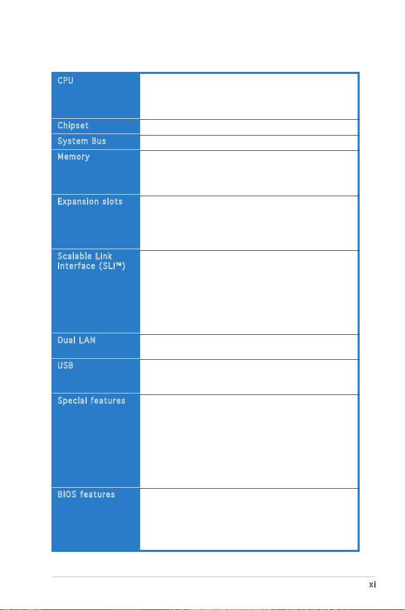
KFN32-D SLI Series specications summary
CPU
Chipset
System Bus
Memory
Expansion slots
Scalable Link
Interface (SLI™)
Dual LAN
USB
Special features
BIOS features
Socket 1207 for next generation AMD® Opteron™ 200
and 800 Series processor
Supports AMD 64 architecture that enables simultaneous
32-bit and 64-bit architecture
NVIDIA® MCP55PRO
2000 MT per second
Dual-channel memory architecture
8 x 240-pin DIMM sockets support registered
ECC DDR2 400/533/667 memory modules
Supports up to 16 GB system memory
2 x PCI Express x16 slots with Scalable Link Interface
(SLI™) support
1 x PCI Express x8 slot
2 x PCI slot 33 MHz/32-bit/5V slots (PCI 2.3)
2 x PCI-X slots
SLI™ mode supports:
- 2 x identical SLI™-ready PCI Express x16 graphics
cards
Single card mode supports (default):
- 1 x PCI Express x16 graphics card on the rst
slot (PCIE_1)
- 1 x PCI Express x16 card on the second slot (PCIE_2)
ASUS EZ Plug™
Dual embedded Broadcom BCM5754 Gigabit LAN controllers
that comply with PCI Express 1.0a specications
Supports up to 10 USB 2.0 ports (four on the rear
panel, three connectors on the mid-borad for up to six
additional ports)
ASUS Smart Fan Technology
ASUS CrashFree BIOS 2
ASUS MyLogo2
ASUS Post Reporter
ASUS EZ Flash
ASUS EZ Plug
ASUS CPU Overheating Protection (C.O.P)
ASUS CPU Parameter Recall (C.P.R)
CPU Warning LED
AMI BIOS, 8 MB LPC, Green, PnP, DMI, SMBIOS 2.4,
ACPI 2.0, Trend Chip Away Virus (TCAV)
Boot from USB FDD/ZIP/HDD/CD
(continued on the next page)
xi
Page 12
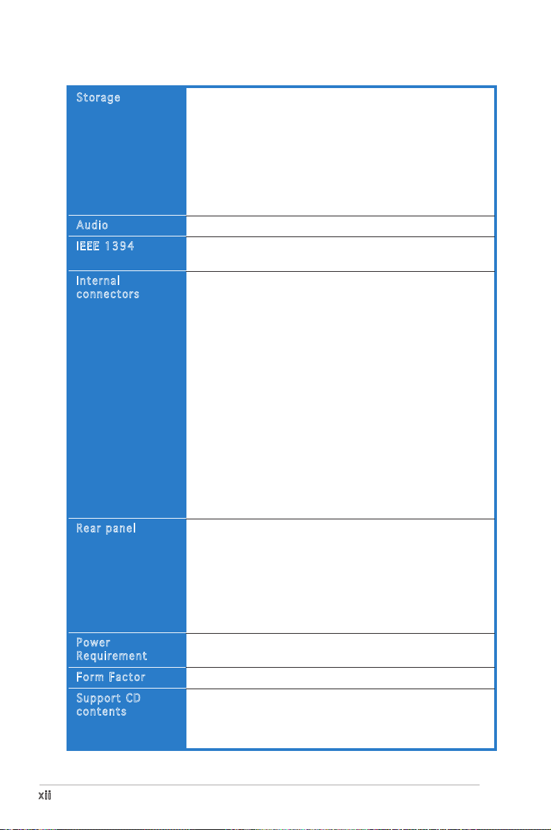
KFN32-D SLI Series specications summary
Storage
Audio
IEEE 1394
Internal
connectors
Rear panel
Power
Requirement
Form Factor
Support CD
contents
NVIDIA® MCP55PRO chipset supports:
- Ultra DMA 133/100/66/33
- 6 x Serial ATA II devices
- RAID 0, RAID 1, RAID 10, RAID 5 and JBOD conguration
(KFN32-D SLI/SAS model only)
LSI1068 SAS RAID controller supports:
- 2 x Serial Attached SCSI Slot with JBOD, RAID 0,
RAID 1, and RAID 1E
Realtek® ALC880 8-channel CODEC
T1 1394 controller supports:
- 2 x IEEE 1394 connectors
1 x Floppy disk drive connector
1 x IDE connector
6 x Serial ATA connectors
2 x Mini-SAS connectors support a total of 8 devices
(KFN32-D SLI/SAS model only)
2 x CPU fan connectors
1 x SMBus header for back-plane
2 x Front fan connectors
2 x Rear fan connectors
1 x 24-pin ATX power connector
1 x 8-pin ATX 12 V power connector
1 x 4-pin ASUS EZ Plug™ connector
3 x USB 2.0 connectors for 6 additional USB 2.0 ports
1 x Internal audio connector (CD)
2 x IEEE 1394 connectors
1 x GAME/MIDI connector
1 x Chassis intrusion connector
1 x Front panel audio connector
1 x Parallel port
2 x S/PDIF out connector
2 x LAN (RJ-45) ports
4 x USB 2.0 ports
1 x Optical S/PDIF out port
1 x PS/2 keyboard port
1 x PS/2 mouse port
8-channel audio ports
SSI power supply (with 24-pin and 8-pin 12 V plugs)
ATX 12 V 2.0 compliant
Extended-ATX form factor:
Device drivers
ASUS Live Update utility
ASUS Server Web-based Management (ASWM)
Anti-virus software
12.0
” x
13.0
” (30.5 cm x 26.7 cm)
*Specications are subject to change without notice.
xii
Page 13

This chapter describes the motherboard
features and the new technologies
it supports.
introduction
Product
1
Page 14

Chapter summary
1
1.1 Welcome! .............................................................................. 1-1
1.2 Package contents ................................................................. 1-1
1.3 Special features .................................................................... 1-2
ASUS KFN32-D SLI Series
Page 15
1.1 Welcome!
Thank you for buying an ASUS® KFN32-D SLI Series motherboard!
The motherboard delivers a host of new features and latest technologies,
making it another standout in the long line of ASUS quality motherboards!
Before you start installing the motherboard, and hardware devices on it,
check the items in your package with the list below.
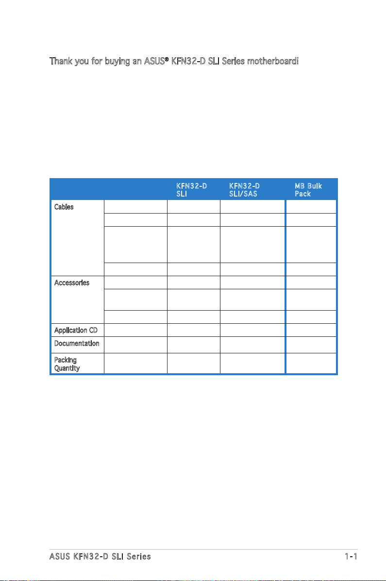
1.2 Package contents
Check your motherboard package for the following items.
KFN 3 2 - D
SLI
Cables SATA signal cable 3 3 -
SATA power cable 3 (dual-plug) 3 (dual-plug) -
3-in-1 Floppy/
Ultra ATA disk
drive cable
SAS cable - 1 -
Accessories I/O shield 1 1 1
CPU retention
module
Screws 2 2 2
Application CD Support CD 1 1 1
Documentation User guide 1 1 1
Packing
Quantity
Motherboard 1 piece per
1 1 -
1 1 1
box
KFN 3 2 - D
SLI / S A S
1 piece per box 10 pieces per
MB B u l k
Pac k
carton
ASUS KFN32-D SLI Series 1-1
Page 16
1.3 Special features
1.3 .1 Pro duc t hi ghl ig ht s
Lat e st pro c es s or t ec h nol o gy
The motherboard comes with a 1207-pin surface mount Land Grid Array
(LGA) socket coded Socket F, designed for the next generation AMD
Opteron™ 200 and 800 series processors. The motherboard with the™ 200 and 800 series processors. The motherboard with the 200 and 800 series processors. The motherboard with the
new socket supports registered DDR2-667/533/400 memory, delivering
advanced performance and ensuring reliable data protection.
Sca l ab l e L i nk Int e rf a ce ( SL I ™) t ec h nol o gy
The NVIDIA® Scalable Link Interface (SLI™) technology allows two graphics
processing units (GPUs) in a single system. This technology takes
advantage of the PCI Express™ bus architecture and features intelligent
hardware and software solutions that allows multiple GPUs to work
together and achieve exceptional graphics performance.
DDR 2 -66 7 m e mor y s u ppo r t
The motherboard supports DDR2 memory which features data transfer
rates of up to 667 MHz to meet the higher bandwidth requirements of the
latest server applications. The dual-channel memory architecture doubles
the bandwidth of your system memory to boost system performance,
eliminating bottlenecks with peak bandwidths of up to 10.7 GB/s.
PCI Ex p res s ™ i nte r fa c e
The motherboard fully supports PCI Express, the latest I/O interconnect
technology that speeds up the PCI bus. PCI Express features point-to-point
serial interconnections between devices and allows higher clockspeeds by
carrying data in packets. This high speed interface is software compatible
with existing PCI or PCI-X specications.
Gig a bi t LA N s o lut i on
The motherboard comes with dual Gigabit LAN controllers and ports to
provide a total solution for your networking needs. The onboard Broadcom®
BCM5754 Gigabit LAN controllers use the PCI Express interface and could
achieve network throughput close to Gigabit bandwidth.
Ser i al ATA II tec h no l ogy
The motherboard supports the Serial ATA II technology through the Serial
ATA interfaces controlled by the NVIDIA® chipset. The SATA specication
allows for thinner, more exible cables with lower pin count, reduced
voltage requirement, and up to 300 MB/s data transfer rate.
1-2 Chapter 1: Product introduction
Page 17
Dua l R A ID s ol u tio n
Onboard RAID controllers provide the motherboard with dual-RAID
functionality that allows you to select the best RAID solution using IDE or
Serial ATA devices.
The NVIDIA® MCP55 Professional allows RAID 0, RAID 1, RAID 0+1, RAID 5
and JBOD conguration for six SATA connectors.
The LSI1068 SAS RAID controller supports 8-Port Serial Attached SCSI/
SATA ports and allows JBOD, RAID 0, RAID 1, and RAID 1E congurations.
8-c h an n el h ig h de f in i tio n a u dio
The motherboard supports 8-channel audio through the onboard ALC880
CODEC with 16-bit DAC, a stereo 16-bit ADC, and an AC97 2.3 compatible
multi-channel audio. It also provides Jack-Sensing function, S/PDIF out
support, interrupt capability and includes the Realtek® proprietary UAJ®
(Universal Audio Jack) technology.
USB 2.0 te c hno log y
The motherboard implements the Universal Serial Bus (USB) 2.0
specication, dramatically increasing the connection speed from the
12 Mbps bandwidth on USB 1.1 to a fast 480 Mbps on USB 2.0. USB 2.0 is
backward compatible with USB 1.1.
IEE E 1 3 94a sup p or t
The IEEE 1394a interface provides high-speed and exible PC connectivity
to a wide range of peripherals and devices compliant to the IEEE 1394a
standard. The IEEE 1394a interface allows up to 400 Mbps transfer rates
through simple, low-cost, high-bandwidth asynchronous (real-time) data
interfacing between computers, peripherals, and consumer electronic
devices such as camcorders, VCRs, printers, TVs, and digital cameras.
Tem p er a tur e , f an, an d vo l ta g e m o ni t ori n g
The CPU temperature is monitored by the ASIC (integrated in the Winbond
hardware monitor) to prevent overheating and damage. The system fan
rotations per minute (RPM) is monitored for timely failure detection. The
ASIC monitors the voltage levels to ensure stable supply of current for
critical components.
ASUS KFN32-D SLI Series 1-3
Page 18
1.3 .2 Inn ova ti ve AS US f e at ur es
Cra s hF r ee B IO S 2
This feature allows you to restore the original BIOS data from the support
CD in case when the BIOS codes and data are corrupted. This protection
eliminates the need to buy a replacement ROM chip.
ASU S S m art Fa n Te c hn o log y
The ASUS Smart Fan technology smartly adjusts the fan speeds according
to the system loading to ensure quiet, cool, and efcient operation.
ASU S M y Log o 2™
This new feature present in the motherboard allows you to personalize and
add style to your system with customizable boot logos.
ASU S P O ST R ep o rte r ™
The motherboard offers a new exciting feature called the ASUS POST
Reporter™ to provide friendly voice messages and alerts during the
Power-On Self-Test (POST) informing you of the system boot status and
causes of boot errors, if any. The bundled Winbond Voice Editor software
lets you to customize the voice messages in different languages.
1-4 Chapter 1: Product introduction
Page 19

This chapter lists the hardware setup
procedures that you have to perform
when installing system components.
It includes description of the jumpers
and connectors on the motherboard.
information
Hardware
2
Page 20

Chapter summary
2.1 Before you proceed .............................................................. 2-1
2.2 Motherboard overview .......................................................... 2-3
2.3 Central Processing Unit (CPU) .............................................. 2-8
2.4 System memory .................................................................. 2-14
2.5 Expansion slots ................................................................... 2-17
2.6 Jumpers .............................................................................. 2-20
2.7 Connectors .........................................................................2-24
ASUS KFN32-D SLI Series
Page 21
2.1 Before you proceed
Take note of the following precautions before you install motherboard
components or change any motherboard settings.
• Make sure that your power supply unit (PSU) can provide at least
the minimum power required by your system.
• Unplug the power cord from the wall socket before touching any
component.
• Use a grounded wrist strap or touch a safely grounded object or
to a metal object, such as the power supply case, before handling
components to avoid damaging them due to static electricity.
• Hold components by the edges to avoid touching the ICs on them.
• Whenever you uninstall any component, place it on a grounded
antistatic pad or in the bag that came with the component.
• Before you install or remove any component, ensure that the ATX
power supply is switched off or the power cord is detached from
the power supply. Failure to do so may cause severe damage to the
motherboard, peripherals, and/or components.
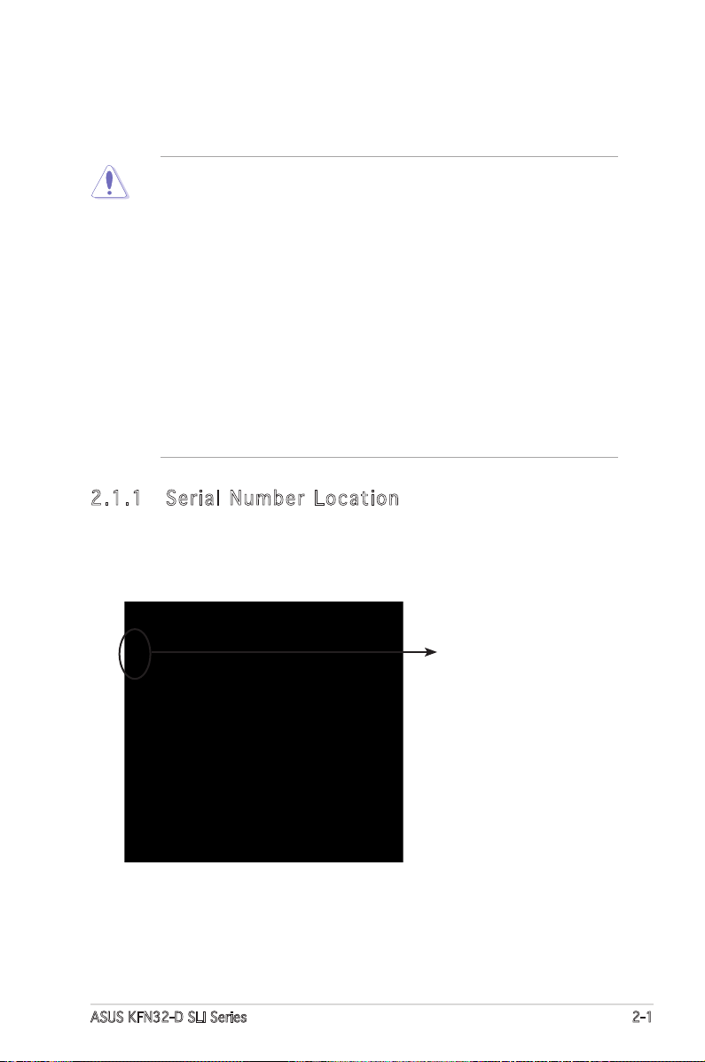
2.1 .1 Ser ial N um ber L oc ati on
Before requesting support from the ASUS Technical Support team, you
must take note of the motherboard’s serial number located on the LPT
printer port.
Serial number
location
ASUS KFN32-D SLI Series 2-1
Page 22
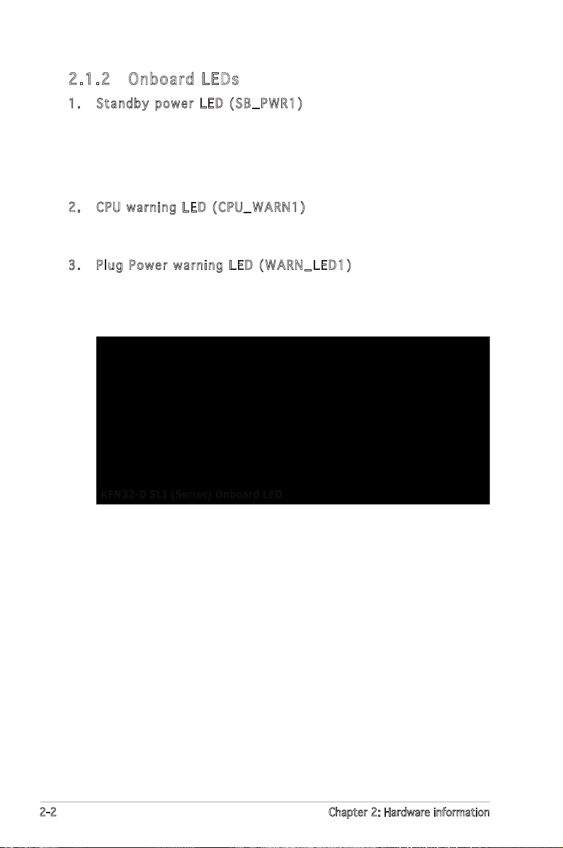
2.1 .2 Onb oar d LE Ds
1. Stan d b y pow e r LED ( S B _PWR 1 )
The motherboard comes with a green standby power LED that lights
up to indicate that the system is ON, in sleep mode, or in soft-off
mode. This is a reminder that you should shut down the system
and unplug the power cable before removing or plugging in any
motherboard component.
2. CPU w a r ning L E D (C P U _ WARN 1 )
The CPU warning LED lights up to indicate that a processor is not
installed or the processor is not installed properly in CPU 1 socket.
3. Plug P o wer w a r ning L E D (W A R N _LED 1 )
The plug power warning LED lights up when you installed two graphics
card but did not connect the ASUS EZ Plug™. The illustration below
shows the location of the onboard LEDs.
2-2 Chapter 2: Hardware information
Page 23
2.2 Motherboard overview
KFN32-D SLI
Before you install the motherboard, study the conguration of your chassis
to ensure that the motherboard ts into it.
Make sure to unplug the power cord before installing or removing the
motherboard. Failure to do so can cause you physical injury and damage
motherboard components.
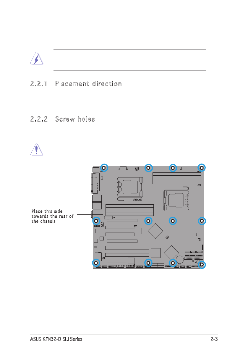
2.2 .1 Pla cem en t dir ec ti on
When installing the motherboard, make sure that you place it into the
chassis in the correct orientation. The edge with external ports goes to the
rear part of the chassis as indicated in the image below.
2.2 .2 Scr ew ho le s
Place twelve (12) screws into the holes indicated by circles to secure the
motherboard to the chassis.
Do not overtighten the screws. Doing so can damage the motherboard.
Pla c e this s i d e
tow a r d s the r e ar of
the c h assis
ASUS KFN32-D SLI Series 2-3
Page 24
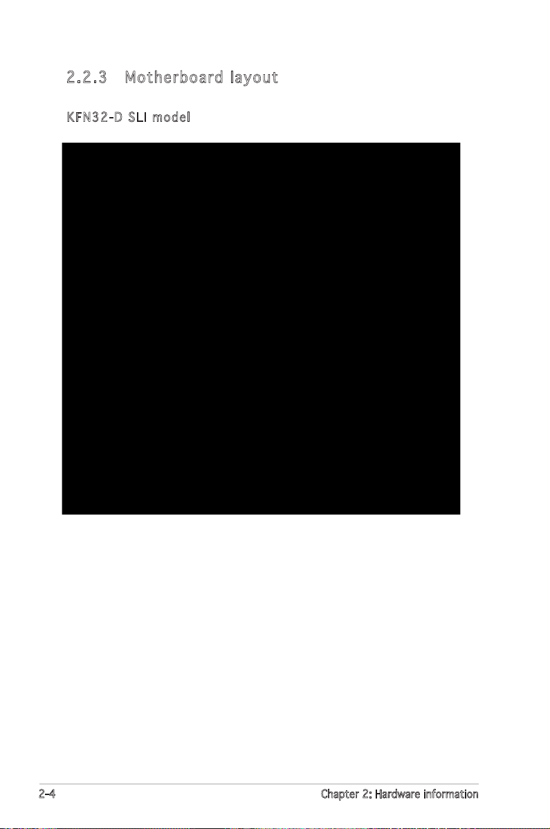
2.2 .3 Mot her bo ar d l ay ou t
KFN3 2 - D SLI m o del
2-4 Chapter 2: Hardware information
Page 25

KFN3 2 - D SLI / S A S mo d e l
ASUS KFN32-D SLI Series 2-5
Page 26
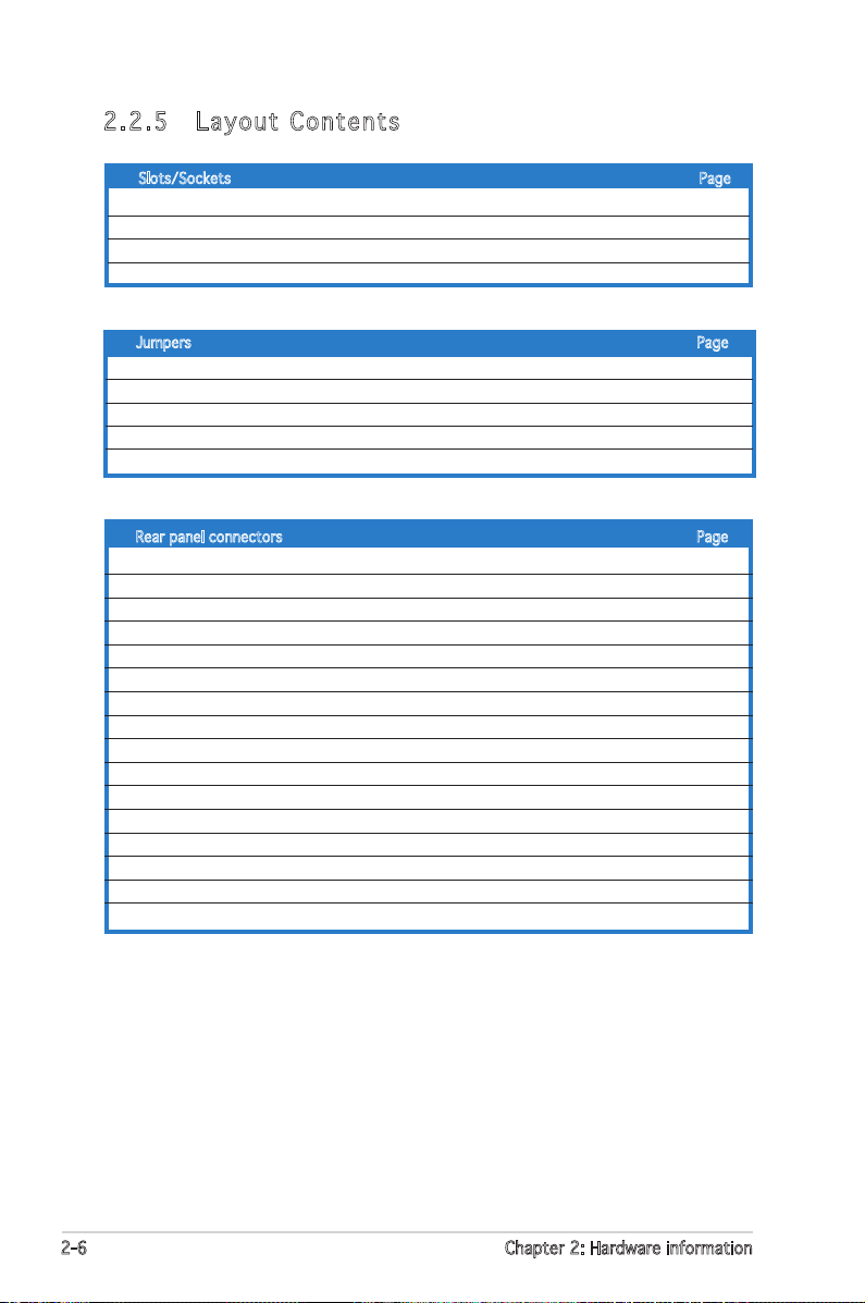
2.2 .5 Lay out C on ten ts
Slots/Sockets Page
1. CPU sockets 2-8
2. DDR2 DIMM sockets 2-14
3. PCI slot 2-19
5. Two PCI Express x16 slota 2-19
Jumpers Page
1. Clear RTC RAM (3-pin CLRTC1) 2-20
2. Keyboard power (3-pin KBPWR1) 2-21
3. Gigabit LAN controller setting (3-pin LAN_EN1, LAN_EN2) 2-21
4. IEEE1394 controller setting (3-pin I394_EN1) 2-22
5. CPU fan pin selection (3-pin FM_CPU1, FM_CPU2) 2-23
Rear panel connectors Page
1. PS/2 mouse port (green) 2-24
2. Parallel port 2-24
3. LAN 1 (RJ-45) port 2-24
4. LAN 2 (RJ-45) port 2-24
5. Rear Speaker Out port (gray) 2-24
6. Side Speaker Out port (black) 2-24
7. Center/Subwoofer port (yellow orange) 2-24
8. Line In port (light blue) 2-25
9. Line Out port (lime) 2-25
10. Microphone port (pink) 2-25
11. USB 2.0 ports 3 and 4 2-25
12. USB 2.0 ports 1 and 2 2-25
13. Serial (COM 1) port 2-25
14. Optical S/PDIF out port 2-25
15. Coaxial S/PDIF out port 2-25
16. PS/2 keyboard port (purple) 2-25
2-6 Chapter 2: Hardware information
Page 27
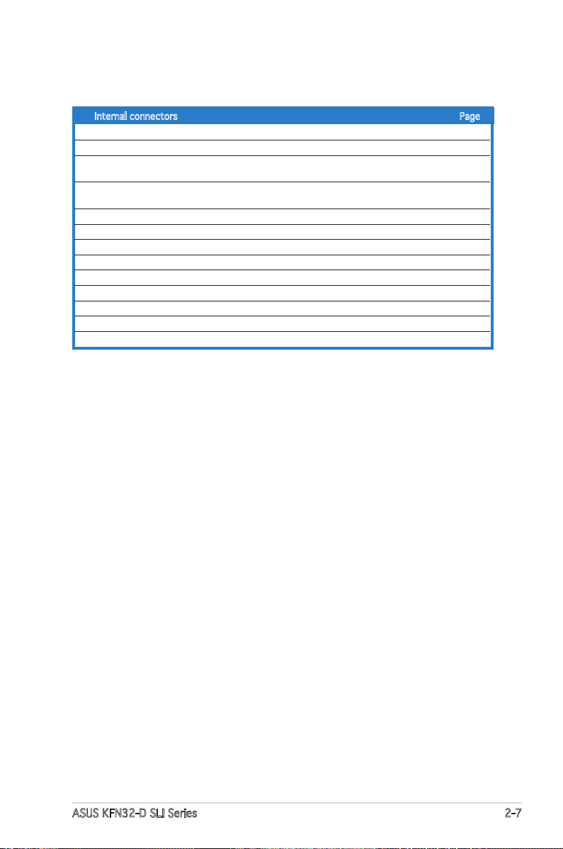
Internal connectors Page
1. Floppy disk drive connector (34-1 pin FLOPPY1) 2-26
2. Primary IDE connectors (40-1 pin PRI_IDE1) 2-27
3. Serial ATA connectors (7-pin SATA1, SATA2,
SATA3, SATA4, SATA5, SATA6) 2-28
4. CPU, Front, and Rear Fan connectors (4-pin CPU_FAN1/2,
3-pin FRONT_FAN1/2, 3-pin REAR_FAN1/2) 2-29
5. Back-plane SMBus connector (6-1 pin BPSMB1) 2-29
6. USB connectors (10-1 pin USB1, USB2, USB3) 2-30
7. IEEE 1394 connectors (10-1 pin IE1394_1, IE1394_2) 2-30
8. SSI power connectors (24-pin ATXPWR1, 8-pin ATX12V1, 4-pin EZ-Plug) 2-31
9. Internal audio connectors (4-pin CD1) 2-32
10. GAME/MIDI port connector (16-1 pin GAME1) 2-32
11. Front panel audio connector (10-1 pin AAFP) 2-33
12. Chassis intrusion connector (4-1 pin CHASSIS) 2-33
13. System panel connector (20-pin PANEL1) 2-34
ASUS KFN32-D SLI Series 2-7
Page 28
2.3 Central Processing Unit (CPU)
The motherboard comes with a surface mount Socket F designed for the
AMD® Opteron® CPU in the Land Grid Array (LGA) package.
•
Upon purchase of the motherboard, make sure that the PnP cap is
on the socket and the socket contacts are not bent. Contact your
retailer immediately if the PnP cap is missing, or if you see any
damage to the PnP cap/socket contacts/motherboard components.
ASUS shoulders the repair cost only if the damage is shipment/
transit-related.
•
Keep the cap after installing the motherboard. ASUS will process
Return Merchandise Authorization (RMA) requests only if the
motherboard comes with the cap on the Socket 1207.
• The product warranty does not cover damage to the socket
contacts resulting from incorrect CPU installation/removal, or
misplacement/loss/incorrect removal of the PnP cap.
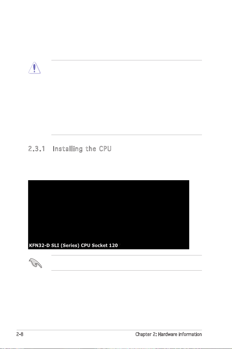
2.3 .1 Ins tal li ng th e CP U
To install a CPU:
1. Locate the CPU socket on the motherboard.
Before installing the CPU, make sure that the cam box is facing towards
you and the load lever is on your left.
2-8 Chapter 2: Hardware information
Page 29
2. Press the load lever with your thumb (A), then move it to the left (B)
until it is released from the retention tab.
Ret e n t ion t a b
Loa d l ever
To prevent damage to the socket pins, do not remove the PnP cap
unless you are installing a CPU.
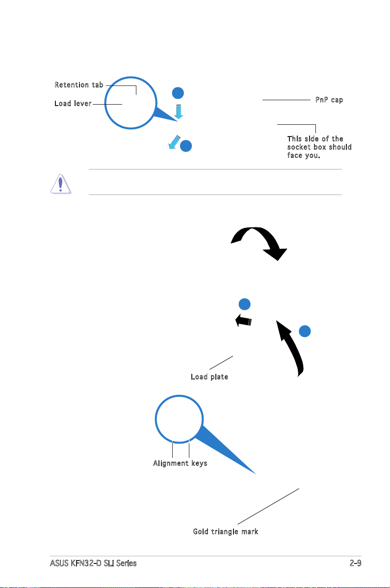
3. Lift the load lever in the
direction of the arrow to a
135º angle.
4. Lift the load plate with
your thumb and forenger
to a 100º angle (A), then
push the PnP cap from
the load plate window to
remove (B).
A
B
B
PnP c a p
Thi s s ide o f t he
soc k e t box s h o u ld
fac e y ou.
A
Loa d p late
5. Position the CPU
over the socket,
making sure that
the gold triangle is
on the bottom-right
corner of the
Ali g n m ent k e y s
socket. The socket
alignment keys
should t into the
CPU notches.
Gol d t riang l e mark
ASUS KFN32-D SLI Series 2-9
Page 30
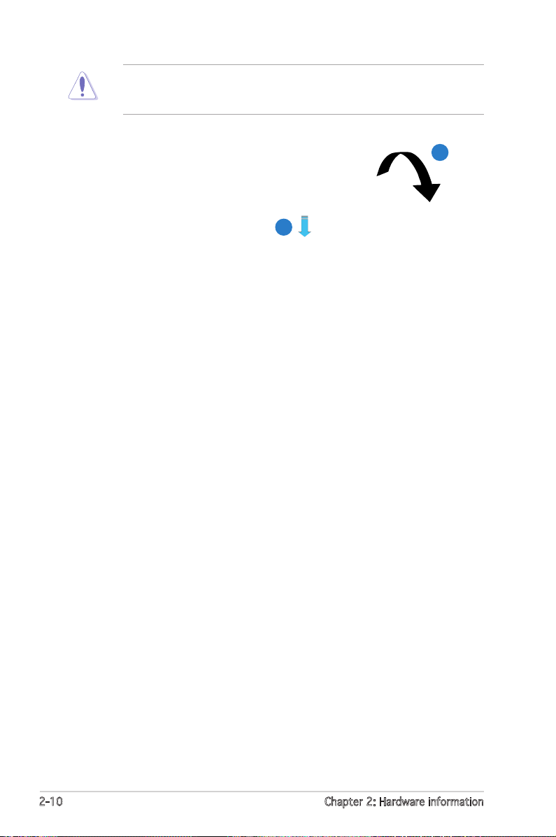
The CPU ts in only one correct orientation. DO NOT force the CPU
into the socket to prevent bending the connectors on the socket and
damaging the CPU.
6. Close the load plate (A), then
push the load lever (B) until
it snaps into the retention
tab.
A
B
2-10 Chapter 2: Hardware information
Page 31

2.3 .3 Ins tal li ng th e he ats in k and f an
The AMD Athlon™ 64 and AMD Opteron™ 64 processors require a specially
designed heatsink and fan assembly to ensure optimum thermal condition
and performance.
Make sure that you use only qualied heatsink and fan assembly.
Follow these steps to install the CPU heatsink and fan.
1. Place the heatsink on top of the installed CPU, making sure that the
heatsink ts properly on the retention module base.
• The retention module base is already installed on the motherboard
upon purchase.
• You do not have to remove the retention module base when
installing the CPU or installing other motherboard components.
• If you purchased a separate CPU heatsink and fan assembly, make
sure that a Thermal Interface Material is properly applied to the CPU
heatsink or CPU before you install the heatsink and fan assembly.
CPU F a n
CPU H e atsin k
Ret e n t ion M o d u le Ba s e
Ret e n t ion b r a c ket l o c kRet e n t ion b r a c ket
Your boxed CPU heatsink and fan assembly should come with installation
instructions for the CPU, heatsink, and the retention mechanism. If the
instructions in this section do not match the CPU documentation, follow
the latter.
ASUS KFN32-D SLI Series 2-11
Page 32

2. Attach one end of the retention bracket to the retention module base.
3. Align the other end of the retention bracket (near the retention
bracket lock) to the retention module base. A clicking sound denotes
that the retention bracket is in place.
Make sure that the fan and
heatsink assembly perfectly
ts the retention mechanism
module base, otherwise you
cannot snap the retention
bracket in place.
4. Push down the retention bracket lock on the retention mechanism to
secure the heatsink and fan to the module base.
2-12 Chapter 2: Hardware information
Page 33

5. When the fan and heatsink assembly is in place, connect the CPU fan
cable to the appropriate connector on the motherboard, CPU_FAN1 or
CPU_FAN2.
• Do not forget to connect the CPU fan connector! Hardware
monitoring errors can occur if you fail to plug this connector.
• If there is only one CPU fan cable, connect it to the connector
labeled CPU_FAN1. Failure to do so may cause hardware monitoring
errors.
ASUS KFN32-D SLI Series 2-13
Page 34

2.4 System memory
2.4 .1 Ove rvi ew
The motherboard comes with eight 240-pin Double Data Rate II (DDR2)
Dual Inline Memory Modules (DIMM) sockets.
The following gure illustrates the location of the sockets:
For CPU 1 Sockets
Channel A DIMM_A1 and DIMM_A2
Channel B DIMM_B1 and DIMM_B2
For CPU 2 Sockets
Channel A DIMM_A3 and DIMM_A4
Channel B DIMM_B3 and DIMM_B4
2-14 Chapter 2: Hardware information
Page 35

2.4 .2 Mem ory C on fig ur at ion s
You may install 256 MB, 512 MB, 1 GB, or 2GB registered ECC DDR2 DIMMs
into the DIMM sockets using the memory congurations in this section.
•
For dual-channel conguration, the total size of memory module(s)
installed per channel must be the same for better performance.
Single CPU:
DIMM_A1+DIMM_B1=DIMM_A2+DIMM_B2
Dual CPU:
DIMM_A1+DIMM_B1=DIMM_A2+DIMM_B2
DIMM_A3+DIMM_B3 =DIMM_A4+DIMM_B4
• Always install DIMMs with the same CAS latency. For optimum
compatibility, we recommend that you obtain memory modules from
the same vendor. Refer to the DDR2 Qualied Vendors List at the
ASUS web site.
Rec o mm e nde d m e mor y c o nfi g ur a tio n f o r C P U1
Mode DIMM_A1 DIMM_A2 DIMM_B1 DIMM_B2
Single channel populated — — —
— populated — —
Dual channel populated — populated —
— populated — populated
populated populated populated populated
Rec o mm e nde d m e mor y c o nfi g ur a tio n f o r C P U2
Mode DIMM_A3 DIMM_A4 DIMM_B3 DIMM_B4
Single channel populated — — —
— populated — —
Dual channel populated — populated —
— populated — populated
populated populated populated populated
ASUS KFN32-D SLI Series 2-15
Page 36

2.4 .3 Ins tal li ng a DI MM
Unplug the power supply before adding or removing DIMMs or other
system components. Failure to do so can cause severe damage to both
the motherboard and the components.
To install a DIMM:
1. Unlock a DIMM socket by
pressing the retaining clips
outward.
2. Align a DIMM on the socket
such that the notch on the
DIMM matches the break on
1
the socket.
3. Firmly insert the DIMM into the
socket until the retaining clips
snap back in place and the
DIMM is properly seated.
• A DDR2 DIMM is keyed with a notch so that it ts in only one
direction. DO NOT force a DIMM into a socket to avoid damaging the
DIMM.
• The DDR2 DIMM sockets do not support DDR DIMMs. DO NOT install
DDR DIMMs to the DDR2 DIMM sockets.
2.4 .4 Rem ovi ng a DI MM
Follow these steps to remove a DIMM.
1. Simultaneously press the retaining
clips outward to unlock the DIMM.
3
DDR 2 D IMM n o t c h
Unl o c k ed re t a i ning c l i p
2
2
Support the DIMM lightly with
your ngers when pressing the
retaining clips. The DIMM might
get damaged when it ips out
with extra force.
1
DDR 2 D IMM n o t c h
1
2. Remove the DIMM from the socket.
2-16 Chapter 2: Hardware information
Page 37

2.5 Expansion slots
In the future, you may need to install expansion cards. The following
sub-sections describe the slots and the expansion cards that they support.
Make sure to unplug the power cord before adding or removing
expansion cards. Failure to do so may cause you physical injury and
damage motherboard components.
2.5 .1 Ins tal li ng an e xp ans io n car d
To install an expansion card:
1. Before installing the expansion card, read the documentation that
came with it and make the necessary hardware settings for the card.
2. Remove the system unit cover (if your motherboard is already
installed in a chassis).
3. Remove the bracket opposite the slot that you intend to use. Keep
the screw for later use.
4. Align the riser card connector with the slot and press rmly until the
riser card is completely seated on the slot.
5. Align the card connector with the slot on the riser card and press
rmly until the card is completely seated on the riser card slot.
6. Secure the card to the chassis with the screw you removed earlier.
7. Replace the system cover.
2.5 .2 Con fig ur in g a n ex pan si on ca rd
After installing the expansion card, congure it by adjusting the software
settings.
1. Turn on the system and change the necessary BIOS settings, if any.
See Chapter 4 for information on BIOS setup.
2. Assign an IRQ to the card. Refer to the tables on the next page.
3. Install the software drivers for the expansion card.
ASUS KFN32-D SLI Series 2-17
Page 38

2.5 .3 Int err up t ass ig nm ent s
Sta n da r d i n te r rup t a s sig n me n ts
IRQ Priority Standard Function
0 1 System Timer
1 2 Keyboard Controller
2 – Programmable interrupt
3 11 Communications Port (COM2)
4 12 Communications Port (COM1)*
5 13 IRQ holder for PCI steering*
6 14 Floppy Disk Controller
7 15 Printer Port (LPT1)*
8 3 System CMOS/Real Time Clock
9 4 IRQ holder for PCI steering*
10 5 IRQ holder for PCI steering*
11 6 IRQ holder for PCI steering*
12 7 PS/2 Compatible Mouse Port*
13 8 Numeric Data Processor
14 9 Primary IDE Channel
15 10 Secondary IDE Channel
* These IRQs are usually available for ISA or PCI devices.
PCI Bu s Nu m be r , I D SE L , a n d I RQ a ss i gnm e nt s
Des c r i ption INT A IN T B I N T C IN T D RE Q # G N T #
PCI slot 1 IRQF# REQ0# GNT0#
PCI E x16 slot IRQA#
PCI E x1 slot IRQA#
PCI E x16 slot IRQA#
Onboard USB controller 1 IRQA#
Onboard USB controller 2 IRQF#
Onboard SATA controller 1 IRQF#
Onboard SATA controller 2 IRQ5#
Onboard SATA controller 3 IRQB#
Onboard PCI E X1 LAN1 IRQ5#
Onboard PCI E X1 LAN2 IRQF#
Onboard 1394 IRQB# REQ2# GNT2#
2-18 Chapter 2: Hardware information
Page 39

2.5 .4 PCI sl ot
The PCI slot supports cards such as
a LAN card, SCSI card, USB card, and
other cards that comply with PCI
specications. The gure shows a
LAN card installed on a PCI slot.
2.5 .5 Two PC I Ex pre ss x 16 sl ot s
This motherboard supports one PCI
Express x16 graphics card or two
SLI-ready PCI Express x16 graphic
cards that comply with the PCI
Express specications. The gure
shows a graphics card installed on the
PCI Express x16 slot.
In Single Video Card mode, only the master PCI Express slot (PCIE_2)
can be used for PCI Express x16 graphics cards.
ASUS KFN32-D SLI Series 2-19
Page 40

2.6 Jumpers
1. Clea r R TC R A M (CLR T C 1 )
This jumper allows you to clear the Real Time Clock (RTC) RAM in
CMOS. You can clear the CMOS memory of date, time, and system
setup parameters by erasing the CMOS RTC RAM data. The onboard
button cell battery powers the RAM data in CMOS, which include
system setup information such as system passwords.
To erase the RTC RAM:
1. Turn OFF the computer and unplug the power cord.
2. Remove the onboard battery.
3. Move the jumper cap from pins 1-2 (default) to pins 2-3. Keep the
cap on pins 2-3 for about 5~10 seconds, then move the cap back
to pins 1-2.
4. Re-install the battery.
5. Plug the power cord and turn ON the computer.
6. Hold down the <Del> key during the boot process and enter BIOS
setup to re-enter data.
Except when clearing the RTC RAM, never remove the cap on CLRTC
jumper default position. Removing the cap will cause system boot failure!
2-20 Chapter 2: Hardware information
Page 41

2. Keyb o a r d po w e r (3- p i n KBP W R 1 )
This jumper allows you to enable or disable the keyboard wake-up
feature. Set this jumper to pins 2-3 (+5VSB) to wake up the computer
when you press a key on the keyboard (the default is the Space Bar).
This feature requires an ATX power supply that can supply at least 1A
on the +5VSB lead, and a corresponding setting in the BIOS.
3. Giga b i t LAN c o ntro l l e r se t t i ng ( 3 - p in L A N _ EN1, L A N_EN 2 )
These jumpers allow you to enable or disable the onboard Broadcom®
BCM5754 Gigabit LAN controllers. The LAN_EN1 jumper controls the
LAN1 port. The LAN_EN2 iumper controls the LAN2 port.
ASUS KFN32-D SLI Series 2-21
Page 42

4. IEEE 1 3 9 4 co n t r o lle r s e tti n g ( 3-pi n 1 394_ E N 1 )
This jumper allows you to enable or disable the IEEE1394 controller.
Set this jumper to 1-2 (Default) to enable the controller.
2-22 Chapter 2: Hardware information
Page 43

5. CPU f a n pin s e lect i o n (3- p i n FM_ C P U 1 , FM _ C P U2)
These jumpers allow you to connect either a 3-pin or a 4-pin fan cable
plug to the CPU fan connectors (CPU_FAN1, CPU_FAN2). Set these
jumpers to pins 1-2 if you are using a 3-pin fan cable plug, or to pins
2-3 if you are using a 4-pin plug.
ASUS KFN32-D SLI Series 2-23
Page 44

2.7 Connectors
SPEED
LED
ACT/LINK
LED
LAN port
4
6
16
1 2
15 14
3
5
7
8
11
12
13
9
10
2.7 .1 Rea r p an el co nn ec tor s
1. PS/2 mouse port (green). This port is for a PS/2 mouse.
2. Parallel port. This 25-pin port connects a parallel printer, a scanner, or
other devices.
3. LAN1 (RJ-45) port. Supported by the BROADCOM® BCM5754 Gigabit
LAN controller, this port allows Gigabit connection to a Local Area
Network (LAN) through a network hub. Refer to the table below for
the LAN port LED indications.
4. LAN2 (RJ-45) port. Supported by the BROADCOM® BCM5754 Gigabit
LAN controller, this port allows Gigabit connection to a Local Area
Network (LAN) through a network hub. Refer to the table below for
the LAN port LED indications.
LAN po r t L E D i ndi c at i ons
ACT/LINK LED SPEED LED
Status Description Status Description
OFF No link OFF 10 Mbps connection
GREEN Linked ORANGE 100 Mbps connection
BLINKING Data activity GREEN 1 Gbps connection
5. Side Speaker Out port (black). This port connects the side speakers in
an 8-channel audio conguration.
center/subwoofer speakers.Rear Speaker Out port (gray). This port
6. Center/Subwoofer port (yellow orange). This port connects the
connects the rear speakers on a 4-channel, 6-channel, or 8-channel
audio conguration.
7. Line In port (light blue). This port connects the tape, CD, DVD player,
or other audio sources.
2-24 Chapter 2: Hardware information
Page 45

8. Line Out port (lime). This port connects a headphone or a speaker. In
4-channel, 6-channel, and 8-channel conguration, the function of this
port becomes Front Speaker Out.
9. Microphone port (pink). This port connects a microphone.
10. Rear woofer port (gray). This port connects the center/subwoofer
speakers.
• Refer to the audio conguration table below for the function of the
audio ports in 2, 4, 6, or 8-channel conguration.
• See section “6.4. 1 Audio congurations” on page 6-15 for details.
Aud i o 2 , 4 , 6, or 8-c han n el con f igu rat i on
Por t H e adset 4- c h a nnel 6 - chann e l 8-ch a n n el
2-channel
Light Blue Line In Line In Line In Line In
Lime Line Out Front Speaker Out Front Speaker Out Front Speaker Out
Pink Mic In Mic In Mic In Mic In
Gray • Rear Speaker Out Rear Speaker Out Rear Speaker Out
Black • • • Side Speaker Out
Orange • • Center/Subwoofer Center/Subwoofer
11. USB 2.0 ports 3 and 4. These two 4-pin Universal Serial Bus (USB)
ports are available for connecting USB 2.0 devices.
12. USB 2.0 ports 1 and 2. These two 4-pin Universal Serial Bus (USB)
ports are available for connecting USB 2.0 devices.
13. Serial (COM 1) port. This 9-pin communication port is for pointing
devices or other serial devices.
14. Coaxial S/PDIF Out port. This port connects an external audio output
device via a coaxial S/PDIF cable.
15. Optical S/PDIF Out port. This port connects an external audio output
device via an optical S/PDIF cable.
16. PS/2 keyboard port (purple). This port is for a PS/2 keyboard.
ASUS KFN32-D SLI Series 2-25
Page 46

2.7 .2 Int ern al c onn ec to rs
1. Flop p y disk d r ive c o n nect o r (34- 1 p in F L O P PY1)
This connector is for the provided oppy disk drive (FDD) signal cable.
Insert one end of the cable to this connector, then connect the other
end to the signal connector at the back of the oppy disk drive.
Pin 5 on the connector is removed to prevent incorrect cable connection
when using a FDD cable with a covered Pin 5.
2-26 Chapter 2: Hardware information
Page 47

2. Prim a r y IDE c o nnec t o r (40 - 1 pin P R I _IDE 1 )
The onboard IDE connector is for Ultra DMA 133/100/66 signal
cable. There are three connectors on each Ultra DMA 133/100/66
signal cable: blue, black, and gray. Connect the blue connector to
the motherboard’s IDE connector, then select one of the following
modes to congure your device(s).
Drive jumper
setting
Single device Cable-Select or
Master
Two devices Cable-Select Master
Master
Slave
Mode Cable of
device(s)
- Black
Slave
Master
Slave
Cable connector
Black
Gray
Black or gray
• Pin 20 on the IDE connector is removed to match the covered hole
on the Ultra DMA cable connector. This prevents incorrect insertion
when you connect the IDE cable.
• Use the 80-conductor IDE cable for Ultra DMA 133/100/66 IDE
devices.
If any device jumper is set as “Cable-Select,” make sure all other device
jumpers have the same setting.
ASUS KFN32-D SLI Series 2-27
Page 48

3. Seri a l ATA c o n nect o r s
KFN32-D SLI
GND
RSATA_TXP1
RSATA_TXN1
GND
RSATA_RXP1
RSATA_RXN1
GND
SATA6
GND
RSATA_TXP1
RSATA_TXN1
GND
RSATA_RXP1
RSATA_RXN1
GND
SATA4
GND
RSATA_TXP1
RSATA_TXN1
GND
RSATA_RXP1
RSATA_RXN1
GND
SATA2
GND
RSATA_TXP1
RSATA_TXN1
GND
RSATA_RXP1
RSATA_RXN1
GND
SATA5
GND
RSATA_TXP1
RSATA_TXN1
GND
RSATA_RXP1
RSATA_RXN1
GND
SATA3
GND
RSATA_TXP1
RSATA_TXN1
GND
RSATA_RXP1
RSATA_RXN1
GND
SATA1
(7-p i n SATA 1 , SATA 2 , SATA 3 , S ATA 4 , S ATA5 , S ATA6 )
Supported by the NVIDIA® MCP55 Professional chipset, these
connectors are for the Serial ATA signal cables for Serial ATA hard
disk drives that allows up to 3Gb/s of data transfer rate.
If you installed Serial ATA hard disk drives, you can create a RAID 0,
RAID 1, RAID 10, RAID 5, or JBOD conguration. Refer to Chapter 5
for details on how to set up the RAID congurations.
These connectors are set to SATA by default. In SATA mode, you can
connect Serial ATA boot or data hard disk drives to these connectors.
If you intent to create a Serial ATA RAID set using these connectors,
enable the RAID function of each port from the nVidia RAID Setup
sub-menu item in the BIOS. See section ‘4.3.5 IDE Conguration” on
page 4-16 for details.
The actual data transfer rate depends on the speed of Serial ATA hard
disks installed.
2-28 Chapter 2: Hardware information
Page 49

4. CPU, F r ont a n d Rea r f an c o n n ecto r s
(4-p i n CPU_ F A N 1/2, 3 - p in F R N T _FAN 1 / 2 ,
3-pi n R EAR_ F A N 1/2)
The fan connectors support cooling fans of 350mA~2000mA (24
W max.) or a total of 1A~3.48A (41.76 W max.) at +12V. Connect
the fan cables to the fan connectors on the motherboard, making
sure that the black wire of each cable matches the ground pin of the
connector.
• Do not forget to connect the fan cables to the fan connectors.
Lack of sufcient air ow inside the system may damage the
motherboard components. These are not jumpers! DO NOT place
jumper caps on the fan connectors!
• All fans feature the ASUS Smart Fan technology.
5. Back p l a ne S M B u s co n n e ctor ( 6 -1 p i n BPSM B 1 )
This connector allows you to connect SMBus (System Management
Bus) devices. Devices communicate with an SMBus host and /or other
SMBus devices using the SMBus interface.
ASUS KFN32-D SLI Series 2-29
Page 50

6. USB c o n nect o r s (10 - 1 p in U S B 1 , US B 2 , USB 3 )
These connectors are for USB 2.0 ports. These connectors comply
with the USB 2.0 specication that supports up to 480 Mbps
connection speed.
7. IEEE 1 3 94 c o n n e cto r s ( 10-1 p i n IE 1 3 9 4_1, I E 1394_ 2 )
These connectors are for the IEEE 1394a module(s). Connect the IEEE
1394 module cable(s) to the connector(s), then install the module to
a slot opening(s) at the back of the system chassis.
2-30 Chapter 2: Hardware information
Page 51

8. SSI power co n n ectors ( 2 4 -pin ATX P W R1, 8- p i n ATX 1 2 V 1,
4-pi n E Z-Pl u g )
These connectors are for SSI power supply plugs. The power supply plugs
are designed to t these connectors in only one orientation. Find the proper
orientation and push down rmly until the connectors completely t.
• Use of an SSI 12 V Specication 2.0-compliant power supply unit
(PSU) that provides a minimum power of 450 W is recommended for
a fully-congured system.
• By default, four ATX12V1 connector pins are covered to prevent
incorrent insertion of a 4-pin ATX +12V power plug. Remove this
cover when using a PSU with an 8-pin ATX +12V power plug.
• Do not forget to connect the 4-pin or 8-pin ATX +12 V power plug;
otherwise, the system will not boot up.
• Use of a PSU with a higher power output is recommended when
conguring a system with more power consuming devices. The system
may become unstable or may not boot up if the power is inadequate.
• You must install a PSU with a higher power rating if you intend to
install additional devices.
ASUS KFN32-D SLI Series 2-31
Page 52

9. Inte r n a l au d i o con n e c tor ( 4 - pin C D 1 )
This connector allows you to receive stereo audio input from sound
sources such as a CD-ROM, TV-tuner, or MPEG card.
The function of this connector is disabled under 8-channel mode.
10. G A M E/MI D I port c o nnec t o r (16 - 1 pin G A M E1)
This connector is for a GAME/MIDI port. Connect the USB/GAME
module cable to this connector, then install the module to a slot
opening at the back of the system chassis. The GAME/MIDI port
connects a joystick or game pad for playing games, and MIDI devices
for playing or editing audio les.
2-32 Chapter 2: Hardware information
Page 53

11. F r o nt p a n e l au d i o con n e c tor ( 1 0 -1 p i n AAFP 1 )
This connector is for a chassis-mounted front panel audio I/O module
that supports either HD Audio or legacy AC’97 audio standard.
We recommend that you connect a high-denition front panel audio
module to this connector to avail of the motherboard’s high-denition
audio capability.
12. C h a ssis i n trus i o n con n e c tor ( 4 - 1 pi n C HASS I S )
This connector is for a chassis-mounted intrusion detection sensor
or switch. Connect one end of the chassis intrusion sensor or switch
cable to this connector. The chassis intrusion sensor or switch sends
a high-level signal to this connector when a chassis component
is removed or replaced. The signal is then generated as a chassis
intrusion event.
By default, the pins labeled “Chassis Signal” and “Ground” are shorted
with a jumper cap. Remove the jumper cap only when you intend to
use the chassis intrusion detection feature.
ASUS KFN32-D SLI Series 2-33
Page 54

13. S y s tem p a n el c o n n ecto r ( 20-p i n PANE L 1 )
This connector supports several chassis-mounted functions.
The system panel connector is color-coded for easy connection. Refer to
the connector description below for details.
• System power LED (Green 3-pin POWERLED)
This 3-pin connector is for the system power LED. Connect the
chassis power LED cable to this connector. The system power LED
lights up when you turn on the system power, and blinks when the
system is in sleep mode.
• Hard disk drive activity (Red 2-pin HDDLED)
This 2-pin connector is for the HDD Activity LED. Connect the HDD
Activity LED cable to this connector. The IDE LED lights up or ashes
when data is read from or written to the HDD.
If an optional SATA add-in card is installed, the read or write activities
of any device connected to the SATA add-in card causes this LED to
light up.
• System warning speaker (Orange 4-pin SPKROUT)
This 4-pin connector is for the chassis-mounted system warning
speaker. The speaker allows you to hear system beeps and warnings.
• Power/Soft-off button (Yellow 2-pin POWERBTN)
This connector is for the system power button. Pressing the power
button turns the system ON or puts the system in SLEEP or SOFT-OFF
mode depending on the BIOS settings. Pressing the power switch for
more than four seconds while the system is ON turns the system OFF.
• Reset button (Blue 2-pin RESETBTN)
This 2-pin connector is for the chassis-mounted reset button for
system reboot without turning off the system power.
2-34 Chapter 2: Hardware information
Page 55

This chapter describes the power up
sequence, the vocal POST messages,
and ways of shutting down the
system.
Powering up
3
Page 56

Chapter summary
3
3.1 Starting up for the rst time ................................................ 3-1
3.2 Powering off the computer ................................................... 3-2
ASUS KFN32-D SLI Series
Page 57

3.1 Starting up for the rst time
1. After making all the connections, replace the system case cover.
2. Be sure that all switches are off.
3. Connect the power cord to the power connector at the back of the
system chassis.
4. Connect the power cord to a power outlet that is equipped with a
surge protector.
5. Turn on the devices in the following order:
a. Monitor
b. External SCSI devices (starting with the last device on the chain)
c. System power
6. After applying power, the system power LED on the system front
panel case lights up. For systems with ATX power supplies, the system
LED lights up when you press the ATX power button. If your monitor
complies with “green” standards or if it has a “power standby”
feature, the monitor LED may light up or switch between orange and
green after the system LED turns on.
The system then runs the Power-On Self-Test (POST). While the tests
are running, the BIOS beeps or additional messages appear on the
screen. If you do not see anything within 30 seconds from the time
you turned on the power, the system may have failed a power-on
test. Check the jumper settings and connections or call your retailer
for assistance.
AMI BI O S b e ep cod e s
Beep Description Error
One beep Keyboard controller error
Refresh Time error
No master drive detected
Two continuous beeps followed by Floppy controller failure
two short beeps
Two continuous beeps followed by Hardware component failure
four short beeps
7. At power on, hold down the <Delete> key to enter the BIOS Setup.
Follow the instructions in Chapter 4.
ASUS KFN32-D SLI Series 3-1
Page 58

3.2 Powering off the computer
3.2 .1 Usi n g th e O S sh ut do wn f unc ti on
IIf you are using Windows® 2000:
1. Click the Start button then click Shut Down...
2. Make sure that the Shut Down option button is selected, then click
the OK button to shut down the computer.
3. The power supply should turn off after Windows® shuts down.
If you are using Windows® XP:
1. Click the Start button then select Turn Off Computer.
2. Click the Turn Off button to shut down the computer.
3. The power supply should turn off after Windows® shuts down.
3.2 .2 Usi n g th e d ua l fu n ct io n p ow er s w it ch
While the system is ON, pressing the power switch for less than four
seconds puts the system to sleep mode or to soft-off mode, depending
on the BIOS setting. Pressing the power switch for more than four seconds
lets the system enter the soft-off mode regardless of the BIOS setting.
Refer to section “4.5 Power Menu” in Chapter 4 for details.
3-2 Chapter 3: Powering up
Page 59

This chapter tells how to change
the system settings through the BIOS
Setup menus. Detailed descriptions
of the BIOS parameters are also
provided.
BIOS setup
4
Page 60

Chapter summary
4
4.1 Managing and updating your BIOS ........................................ 4-1
4.2 BIOS setup program ............................................................ 4-10
4.3 Main menu ........................................................................... 4-13
4.4 Advanced menu .................................................................. 4-18
4.5 Power menu ........................................................................ 4-26
4.6 Boot menu .......................................................................... 4-30
4.7 Exit menu ............................................................................ 4-34
ASUS KFN32-D SLI Series
Page 61

4.1 Managing and updating your BIOS
The following utilities allow you to manage and update the motherboard
Basic Input/Output System (BIOS) setup.
1. ASUS AFUDOS (Updates the BIOS in DOS mode using a bootable oppy
disk.)
2. ASUS CrashFree BIOS 2 (Updates the BIOS using a bootable oppy
disk or the motherboard support CD when the BIOS le fails or gets
corrupted.)
3. ASUS EZ Flash (Updates the BIOS in DOS mode using a oppy disk or
the motherboard support CD.)
4. ASUS Update (Updates the BIOS in Windows® environment.)
Refer to the corresponding sections for details on these utilities.
Save a copy of the original motherboard BIOS le to a bootable oppy
disk in case you need to restore the BIOS in the future. Copy the original
motherboard BIOS using the ASUS Update or AFUDOS utilities.
4.1 .1 Cre ati ng a bo ot ab le fl op py di sk
1. Do either one of the following to create a bootable oppy disk.
DOS environment
a. Insert a 1.44MB oppy disk into the drive.
b. At the DOS prompt, type format A:/S then press <Enter>.
Windows® XP environment
a. Insert a 1.44 MB oppy disk to the oppy disk drive.
b. Click Start from the Windows® desktop, then select My Computer.
c. Select the 3 1/2 Floppy Drive icon.
d. Click File from the menu, then select Format. A Format 3 1/2
Floppy Disk window appears.
e. Windows® XP users: Select Create an MS-DOS startup disk from
the format options eld, then click Start.
2. Copy the original or the latest motherboard BIOS le to the bootable
oppy disk.
ASUS KFN32-D SLI Series 4-1
Page 62

4.1 .2 AFU D OS u ti l it y
The AFUDOS utility allows you to update the BIOS le in DOS environment
using a bootable oppy disk with the updated BIOS le. This utility also
allows you to copy the current BIOS le that you can use as backup when
the BIOS fails or gets corrupted during the updating process.
Cop y in g th e c u rre n t B IOS
To copy the current BIOS le using the AFUDOS utility:
• Make sure that the oppy disk is not write-protected and has at
least 1.1MB free space to save the le.
• The succeeding BIOS screens are for reference only. The actual BIOS
screen displays may not be same as shown.
1. Copy the AFUDOS utility (afudos.exe) from the motherboard support
CD to the bootable oppy disk you created earlier.
2. Boot the system in DOS mode, then at the prompt type:
afudos /o[lename]
where the [lename] is any user-assigned lename not more than
eight alphanumeric characters for the main lename and three
alphanumeric characters for the extension name.
A:\>afudos /oOLDBIOS1.rom
Mai n f ilena m e Ex t e n sion n a m e
3. Press <Enter>. The utility copies the current BIOS le to the oppy
disk.
A:\>afudos /oOLDBIOS1.rom
AMI Firmware Update Utility - Version 1.19(ASUS V2.07(03.11.24BB))
Copyright (C) 2002 American Megatrends, Inc. All rights reserved.
Reading ash ..... done
Write to le...... ok
A:\>
The utility returns to the DOS prompt after copying the current BIOS
le.
4-2 Ch a p t e r 4 : B I O S s e t u p
Page 63

Upd a ti n g t h e B IOS fi l e
To update the BIOS le using the AFUDOS utility:
1. Visit the ASUS website (www.asus.com) and download the latest BIOS
le for the motherboard. Save the BIOS le to a bootable oppy disk.
Write the BIOS lename on a piece of paper. You need to type the exact
BIOS lename at the DOS prompt.
2. Copy the AFUDOS utility (afudos.exe) from the motherboard support
CD to the bootable oppy disk you created earlier.
3. Boot the system in DOS mode, then at the prompt type:
afudos /i[lename]
where [lename] is the latest or the original BIOS le on the bootable
oppy disk.
A:\>afudos /iKFN32-D.ROM
4. The utility veries the le and starts updating the BIOS.
A:\>afudos /iKFN32-D.ROM
AMI Firmware Update Utility - Version 1.19(ASUS V2.07(03.11.24BB))
Copyright (C) 2002 American Megatrends, Inc. All rights reserved.
WARNING!! Do not turn off power during ash BIOS
Reading le ....... done
Reading ash ...... done
Advance Check ......
Erasing ash ...... done
Writing ash ...... 0x0008CC00 (9%)
Do not shut down or reset the system while updating the BIOS to
prevent system boot failure!
ASUS KFN32-D SLI Series 4-3
Page 64

5. The utility returns to the DOS prompt after the BIOS update process is
completed. Reboot the system from the hard disk drive.
A:\>afudos /iKFN32-D.ROM
AMI Firmware Update Utility - Version 1.19(ASUS V2.07(03.11.24BB))
Copyright (C) 2002 American Megatrends, Inc. All rights reserved.
WARNING!! Do not turn off power during ash BIOS
Reading le ....... done
Reading ash ...... done
Advance Check ......
Erasing ash ...... done
Writing ash ...... done
Verifying ash .... done
Please restart your computer
A:\>
4-4 Ch a p t e r 4 : B I O S s e t u p
Page 65

4.1 .3 ASU S C ra sh F re e BI O S 2 ut i li ty
The ASUS CrashFree BIOS 2 is an auto recovery tool that allows you to
restore the BIOS le when it fails or gets corrupted during the updating
process. You can update a corrupted BIOS le using the motherboard
support CD or the oppy disk that contains the updated BIOS le.
• Prepare the motherboard support CD or the oppy disk containing
the updated motherboard BIOS before using this utility.
• Make sure that you rename the original or updated BIOS le in the
oppy disk to KFN32-D.ROM.
Rec o ve r ing th e BI O S f rom a f lop p y d isk
To recover the BIOS from a oppy disk:
1. Turn on the system.
2. Insert the oppy disk with the original or updated BIOS le to the
oppy disk drive.
3. The utility displays the following message and automatically checks
the oppy disk for the original or updated BIOS le.
Bad BIOS checksum. Starting BIOS recovery...
Checking for oppy...
When found, the utility reads the BIOS le and starts ashing the
corrupted BIOS le.
Bad BIOS checksum. Starting BIOS recovery...
Checking for oppy...
Floppy found!
Reading le “KFN32-D.ROM”. Completed.
Start ashing...
DO NOT shut down or reset the system while updating the BIOS! Doing
so can cause system boot failure!
4. Restart the system after the utility completes the updating process.
ASUS KFN32-D SLI Series 4-5
Page 66

Rec o ve r ing th e BI O S f rom th e su p po r t C D
To recover the BIOS from the support CD:
1. Remove any oppy disk from the oppy disk drive, then turn on the
system.
2. Insert the support CD to the optical drive.
3. The utility displays the following message and automatically checks
the oppy disk for the original or updated BIOS le.
Bad BIOS checksum. Starting BIOS recovery...
Checking for oppy...
When no oppy disk is found, the utility automatically checks the
optical drive for the original or updated BIOS le. The utility then
updates the corrupted BIOS le.
Bad BIOS checksum. Starting BIOS recovery...
Checking for oppy...
Floppy not found!
Checking for CD-ROM...
CD-ROM found!
Reading le “KFN32-D.ROM”. Completed.
Start ashing...
DO NOT shut down or reset the system while updating the BIOS! Doing
so can cause system boot failure!
4. Restart the system after the utility completes the updating process.
The recovered BIOS may not be the latest BIOS version for this
motherboard. Visit the ASUS website (www.asus.com) to download the
latest BIOS le.
4-6 Ch a p t e r 4 : B I O S s e t u p
Page 67

4.1 .4 ASU S E Z Fl a sh u ti l it y
The ASUS EZ Flash feature allows you to update the BIOS without having
to go through the long process of booting from a oppy disk and using
a DOS-based utility. The EZ Flash utility is built-in the BIOS chip so it is
accessible by pressing <Alt> + <F2> during the Power-On Self-Test (POST).
To update the BIOS using EZ Flash:
1. Visit the ASUS website (www.asus.com) to download the latest BIOS
le for the motherboard and rename the le as KFN32-D.ROM.
2. Save the BIOS le to a oppy disk, then restart the system.
3. Press <Alt> + <F2> during POST to display the following.
EZFlash starting BIOS update
Checking for oppy...
4. Insert the oppy disk that contains the BIOS le to the oppy disk
drive. When the correct BIOS le is found, EZ Flash performs the BIOS
update process and automatically reboots the system when done.
EZFlash starting BIOS update
Checking for oppy...
Floppy found!
Reading le “KFN32-D.ROM”. Completed.
Start erasing.......|
Start programming...|
Flashed successfully. Rebooting.
• Do not shut down or reset the system while updating the BIOS to
prevent system boot failure!
• A “Floppy not found!” error message appears if there is no oppy
disk in the drive. A “KFN32-D.ROM not found!” error message
appears if the correct BIOS le is not found in the oppy disk. Make
sure that you rename the BIOS le as KFN32-D.ROM.
ASUS KFN32-D SLI Series 4-7
Page 68

4.1 .5 ASU S U pd at e u ti li t y
The ASUS Update is a utility that allows you to manage, save, and update
the motherboard BIOS in Windows® environment. The ASUS Update utility
allows you to:
• Save the current BIOS file
• Download the latest BIOS file from the Internet
• Update the BIOS from an updated BIOS file
• Update the BIOS directly from the Internet, and
• View the BIOS version information.
This utility is available in the support CD that comes with the motherboard
package.
ASUS Update requires an Internet connection either through a network
or an Internet Service Provider (ISP).
Ins t al l ing AS U S U p dat e
To install ASUS Update:
1. Place the support CD in the optical drive. The Drivers menu appears.
2. Click the Utilities tab, then click Install ASUS Update VX.XX.XX.
3. The ASUS Update utility is copied to your system.
Quit all Windows® applications before you update the BIOS using this
utility.
4-8 Ch a p t e r 4 : B I O S s e t u p
Page 69

Upd a ti n g t h e B IOS th r oug h t h e I n te r net
To update the BIOS through the Internet:
1. Launch the ASUS Update utility from the Windows® desktop by
clicking Start > Programs > ASUS > ASUSUpdate > ASUSUpdate. The
ASUS Update main window appears.
2. Select Update BIOS from
the Internet option from the
drop-down menu, then click
Next.
ASUS KFN32-D SLI Series 4-9
3. Select the ASUS FTP site
nearest you to avoid network
trafc, or click Auto Select.
Click Next.
Page 70

4. From the FTP site, select the
BIOS version that you wish to
download. Click Next.
5. Follow the screen instructions to
complete the update process.
The ASUS Update utility is
capable of updating itself
through the Internet. Always
update the utility to avail all
its features.
Upd a ti n g t h e B IOS th r oug h a BIO S f i le
To update the BIOS through a BIOS le:
1. Launch the ASUS Update utility from the Windows® desktop by
clicking Start > Programs > ASUS > ASUSUpdate > ASUSUpdate. The
ASUS Update main window appears.
2. Select Update BIOS from a le
option from the drop-down menu,
then click Next.
3. Locate the BIOS le from the Open window, then click Save.
4. Follow the screen instructions to complete the update process.
4-10 Ch a p t e r 4 : B I O S s e t u p
Page 71

4.2 BIOS setup program
This motherboard supports a programmable rmware chip that you can
update using the provided utility described in section “4.1 Managing and
updating your BIOS.”
Use the BIOS Setup program when you are installing a motherboard,
reconguring your system, or prompted to “Run Setup”. This section
explains how to congure your system using this utility.
Even if you are not prompted to use the Setup program, you can change
the conguration of your computer in the future. For example, you can
enable the security password feature or change the power management
settings. This requires you to recongure your system using the BIOS Setup
program so that the computer can recognize these changes and record
them in the CMOS RAM of the rmware hub.
The rmware hub on the motherboard stores the Setup utility. When you
start up the computer, the system provides you with the opportunity to
run this program. Press <Del> during the Power-On Self-Test (POST) to
enter the Setup utility; otherwise, POST continues with its test routines.
If you wish to enter Setup after POST, restart the system by pressing
<Ctrl> + <Alt> + <Del>, or by pressing the reset button on the system
chassis. You can also restart by turning the system off and then back on.
Do this last option only if the rst two failed.
The Setup program is designed to make it as easy to use as possible. Being
a menu-driven program, it lets you scroll through the various sub-menus
and make your selections from the available options using the navigation
keys.
• The default BIOS settings for this motherboard apply for most
conditions to ensure optimum performance. If the system becomes
unstable after changing any BIOS settings, load the default settings
to ensure system compatibility and stability. Select the Load Setup
Defaults item under the Exit Menu. See section “4.7 Exit Menu.”
• The BIOS setup screens shown in this section are for reference
purposes only, and may not exactly match what you see on your
screen.
• Visit the ASUS website (www.asus.com) to download the latest BIOS
le for this motherboard.
ASUS KFN32-D SLI Series 4-11
Page 72

4.2 .1 BIO S m en u scr ee n
Men u b ar
System Time [11:51:19]
System Date [Fri 01/6/2006]
Legacy Diskette A [1.44M, 3.5 in.]
Primary IDE Master :[Not Detected]
Primary IDE Slave :[Not Detected]
Serial-ATA 0 Primary Channel :[Not Detected]
Serial-ATA 0 Secondary Channel :[Not Detected]
Serial-ATA 1 Primary Channel :[Not Detected]
Serial-ATA 1 Secondary Channel :[Not Detected]
Serial-ATA 2 Primary Channel :[Not Detected]
Serial-ATA 2 Secondary Channel :[Not Detected]
IDE Conguration
System Information
Sub - m e nu it e m s
Con f i g urati o n field sMen u i tems
Gen e r a l hel p
Use [ENTER], [TAB]
or [SHIFT-TAB] to
select a eld.
Use [+] or [-] to
congure system
time.
Nav i g a tion k e y s
4.2 .2 Men u b ar
The menu bar on top of the screen has the following main items:
Main For changing the basic system conguration
Advanced For changing the advanced system settings
Power For changing the advanced power management (APM)
conguration
Boot For changing the system boot conguration
Exit For selecting the exit options and loading default
settings
To select an item on the menu bar, press the right or left arrow key on the
keyboard until the desired item is highlighted.
4.2 .3 Nav iga ti on ke ys
At the bottom right corner of a menu screen are the navigation keys for
that particular menu. Use the navigation keys to select items in the menu
and change the settings.
Some of the navigation keys differ from one screen to another.
4-12 Ch a p t e r 4 : B I O S s e t u p
Page 73

4.2 .4 Men u i te ms
System Time [11:51:19]
System Date [Fri 01/6/2006]
Legacy Diskette A [1.44M, 3.5 in]
Primary IDE Master :[Not Detected]
Primary IDE Slave :[Not Detected]
Serial-ATA 0 Primary Channel :[Not Detected]
Serial-ATA 0 Secondary Channel :[Not Detected]
Serial-ATA 1 Primary Channel :[Not Detected]
Serial-ATA 1 Secondary Channel :[Not Detected]
Serial-ATA 2 Primary Channel :[Not Detected]
Serial-ATA 2 Secondary Channel :[Not Detected]
System Information
Use [ENTER], [TAB]
or [SHIFT-TAB] to
select a field.
Use [+] or [-] to
configure system time.
Select Screen
Select Item
+- Change Field
Tab Select Field
F1 General Help
F10 Save and Exit
ESC Exit
IDE Configuration :[Not Detected]
Select Screen
Select Item
+- Change Option
F1 General Help
F10 Save and Exit
ESC Exit
South Bridge/MCP55 Chipset
LPC P2P P2P [+ +/- +/-]
CPU/LTD Spread Spectrum [Disabled]
PCIE Spread Spectrum [Enabled]
MCP PCI-Express Frequency, MHz [100]
SATA Spread Spectrum [Enabled]
Primary Graphics Adapter [PCI Express -> PCI]
PMU [Enabled]
AZALIA AUDIO [Auto]
The highlighted item on the menu bar
displays the specic items for that
menu. For example, selecting Main shows
the Main menu items.
The other items (Advanced, Power,
Boot, and Exit) on the menu bar have
Mai n m enu i t e m s
their respective menu items.
4.2 .5 Sub -me nu i tem s
A solid triangle before each item on any menu screen means that the
iteam has a sub-menu. To display the sub-menu, select the item and press
<Enter>.
4.2 .6 Con fig ur at ion f ie lds
These elds show the values for the menu items. If an item is usercongurable, you can change the value of the eld opposite the item. You
cannot select an item that is not user-congurable.
A congurable eld is enclosed in brackets, and is highlighted when
selected. To change the value of a eld, select it then press <Enter> to
display a list of options. Refer to “4.2.7 Pop-up window.”
4.2 .7 Pop -up w in dow
Select a menu item then press <Enter> to display a pop-up window with
the conguration options for that item.
4.2 .8 Scr oll b ar
A scroll bar appears on the right side
of a menu screen when there are items
that do not t on the screen. Press the
Up/Down arrow keys or <Page Up>
/<Page Down> keys to display the other
items on the screen.
4.2 .9 Gen era l he lp
At the top right corner of the menu
screen is a brief description of the selected item.
ASUS KFN32-D SLI Series 4-13
Pop - u p wind o w
Scr o l l bar
Page 74

4.3 Main menu
When you enter the BIOS Setup program, the Main menu screen appears,
giving you an overview of the basic system information.
Refer to section “4.2.1 BIOS menu screen” for information on the menu
screen items and how to navigate through them.
System Time [11:51:19]
System Date [Fri 01/6/2006]
Legacy Diskette A [1.44M, 3.5 in.]
Primary IDE Master :[Not Detected]
Primary IDE Slave :[Not Detected]
Serial-ATA 0 Primary Channel :[Not Detected]
Serial-ATA 0 Secondary Channel :[Not Detected]
Serial-ATA 1 Primary Channel :[Not Detected]
Serial-ATA 1 Secondary Channel :[Not Detected]
Serial-ATA 2 Primary Channel :[Not Detected]
Serial-ATA 2 Secondary Channel :[Not Detected]
IDE Conguration
System Information
Use [ENTER], [TAB]
or [SHIFT-TAB] to
select a eld.
Use [+] or [-] to
congure system
time.
4.3 .1 Sys tem T im e [ xx :x x:x xx x]
Allows you to set the system time.
4.3 .2 Sys tem D at e [ Da y xx/ xx /x xxx ]
Allows you to set the system date.
4.3 .3 Leg acy D is ket te A [1 .4 4M , 3 .5 i n .]
Sets the type of oppy drive installed. Conguration options: [Disabled]
[360K, 5.25 in.] [1.2M , 5.25 in.] [720K , 3.5 in.] [1.44M, 3.5 in.]
[2.88M, 3.5 in.]
4.3 .4 Pri mar y ID E M as te r/S la ve , T hi rd , F ou rt h,
Fif th , Six th , Sev en th an d Ei ght h ID E M as te r
The BIOS automatically detects the connected IDE devices. There is a
separate sub-menu for each IDE device. Select a device item, then press
<Enter> to display the IDE device information.
4-14 Ch a p t e r 4 : B I O S s e t u p
Page 75

Primary IDE Master
Device : Hard Disk
Vendor : ST320413A
Size : 20.0GB
LBA Mode : Supported
Block Mode : 16 Sectors
PIO Mode : Supported
Async DMA : MultiWord DMA-2
Ultra DMA : Ultra DMA-5
SMART Monitoring: Supported
Type [Auto]
LBA/Large Mode [Auto]
Block(Multi-Sector Transfer) [Auto]
PIO Mode [Auto]
DMA Mode [Auto]
SMART Monitoring [Auto]
32Bit Data Transfer [Enabled]
The BIOS automatically detects the values opposite the dimmed items
(Device, Vendor, Size, LBA Mode, Block Mode, PIO Mode, Async DMA, Ultra
DMA, and SMART monitoring). These values are not user-congurable.
These items show N/A if no IDE device is installed in the system.
Typ e [ A uto ]
Selects the type of IDE drive. Setting to [Auto] allows automatic selection
of the appropriate IDE device type. Select [CDROM] if you are specically
conguring a CD-ROM drive. Select [ARMD] (ATAPI Removable Media
Device) if your device is either a ZIP, LS-120, or MO drive.
Conguration options: [Not Installed] [Auto] [CDROM] [ARMD]
LBA / La r ge M od e [A u to ]
Enables or disables the LBA mode. Setting to [Auto] enables the LBA mode
if the device supports this mode, and if the device was not previously
formatted with LBA mode disabled. Conguration options: [Disabled]
[Auto]
Blo c k ( Mul t i- s ect o r T ran s fe r ) [ A ut o ]
Enables or disables data multi-sectors transfers. When set to [Auto], the
data transfer from and to the device occurs multiple sectors at a time if
the device supports multi-sector transfer feature. When set to [Disabled],
the data transfer from and to the device occurs one sector at a time.
Conguration options: [Disabled] [Auto]
PIO Mo d e [ A ut o ]
Selects the PIO mode.
Conguration options: [Auto] [0] [1] [2] [3] [4]
ASUS KFN32-D SLI Series 4-15
Page 76

DMA Mo d e [ A ut o ]
Selects the DMA mode.
Conguration options: [Auto] [SWDMA0] [SWDMA1] [SWDMA2]
[MWDMA0] [MWDMA1] [MWDMA2] [UDMA0] [UDMA1] [UDMA2] [UDMA3]
[UDMA4] [UDMA5]
SMA R T M oni t or i ng [ Au t o]
Sets the Smart Monitoring, Analysis, and Reporting Technology.
Conguration options: [Auto] [Disabled] [Enabled]
32B i t D ata Tra nsf e r [ Ena b led ]
Enables or disables 32-bit data transfer.
Conguration options: [Disabled] [Enabled]
4.3 .5 IDE Co nf ig ura ti on
The items in this menu allow you to set or change the congurations for
the IDE devices installed in the system. Select an item then press <Enter>
if you wish to congure the item.
IDE Conguration
OnBoard PCI IDE Controller [Enabled]
Serial-ATA Devices [Device 0/1/2]
nVidia RAID Setup
Hard Disk Write Protect [Disabled]
IDE Dectect Time Out (Sec) [35]
ATA(PI) 80Pin Cable Detection [Host]
DISABLED: disables
the intergrated IDE
Controller.
PRIMARY: enables
only the Primary IDE
Controller.
SECODARY: enables
only the Secondary
IDE Controller.
BOTH: enables both
IDE Controllers.
OnB o ar d PC I I D E C o nt r oll e r [ Ena b le d ]
Enables or disables primary IDE controllers.
Conguration options: [Disabled] [Enabled]
Ser i al - ATA De v ice s [ D evi c e 0 /1/ 2 ]
Enables or disables the SATA0/1/2 IDE Interfaces.
Conguration options: [Disabled] [Device 0] [Device 0/1] [Device 0/1/2]
Har d D i sk W ri t e P r ot e ct [ Di s abl e d]
Enables or disables the hard disk wirte protection. This will be effective
only if device is accessed through BIOS.
Conguration options: [Disabled] [Enabled]
4-16 Ch a p t e r 4 : B I O S s e t u p
Page 77

IDE De t ect Ti m e O u t [ 35]
Selects the time out value for detecting ATA/ATAPI devices.
Conguration options: [0] [5] [10] [15] [20] [25] [30] [35]
ATA ( PI ) 80 P in Cab l e D ete c tio n [ H ost ]
Selects the mechanism for detecting 80Pin ATA(PI) Cable.
Conguration options: [Host & Device] [Host] [Device]
RAI D S e tu p
RAID Setup
nVidia RAID Function [Disabled]
nVidia RAID Function [Disabled]
Enables or disables the NVIDIA® RAID function.
Conguration options: [Disabled] [Enabled]
The following items appear when this item is Enabled.
SATA0 Primary Channel [Disabled]
Sets the SATA0 Primary Channel as RAID.
Conguration options: [Disabled] [Enabled]
SATA0 Secondary Channel [Disabled]
Sets the SATA0 Secondary Channel as RAID.
Conguration options: [Disabled] [Enabled]
SATA1 Primary Channel [Disabled]
Sets the SATA1 Primary Channel as RAID.
Conguration options: [Disabled] [Enabled]
SATA1 Secondary Channel [Disabled]
Sets the SATA1 Secondary Channel as RAID.
Conguration options: [Disabled] [Enabled]
SATA2 Primary Channel [Disabled]
Sets the SATA2 Primary Channel as RAID.
Conguration options: [Disabled] [Enabled]
SATA2 Secondary Channel [Disabled]
Sets the SATA2 Secondary Channel as RAID.
Conguration options: [Disabled] [Enabled]
Disable/Enable nVidia
ROM.
ASUS KFN32-D SLI Series 4-17
Page 78

4.3 .6 Sys tem I nf orm at io n
Select Screen
Select Item
Enter Go to Sub-screen
F1 General Help
F10 Save and Exit
ESC Exit
This menu gives you an overview of the general system specications. The
BIOS automatically detects the items in this menu.
AMIBIOS
Version : 0128
Build Date : 07/24/06
Processor
Type : AMD Opteron(tm) Processor 146
Speed : 2413 MHz
Count : 2
System Memory
Size : 1024MB
AMI BI O S
Displays the auto-detected BIOS information
Pro c es s or
Displays the auto-detected CPU specication
Sys t em Mem o ry
Displays the auto-detected system memory
4.4 Advanced menu
The Advanced menu items allow you to change the settings for the CPU
and other system devices.
Take caution when changing the settings of the Advanced menu items.
Incorrect eld values can cause the system to malfunction.
JumperFree Conguration
Speech Conguration
CPU Conguration
Chipset
Onboard Devices Conguration
PCIPnP
MPS Conguration
USB Conguration
Trusted Computing
4-18 Ch a p t e r 4 : B I O S s e t u p
Adjust system
frequency
Page 79

4.4 .1 Jum per Fr ee Co nf ig ura ti on
The items in this menu allow you to congure the system frequency/
voltage.
Cong System Frequency/Voltage
CPU Frequency MHz [200.9]
CPU1 DDR2 Voltage [1.80V]
CPU2 DDR2 Voltage [1.80V]
1.4V Chipset Voltage [1.45V]
1.5V Chipset Voltage [1.50V]
CPU1 Voltage Control [Default VID]
CPU2 Voltage Control [Default VID]
Hyper Transport Voltage [1.20V]
Adjust CPU1 DDR2
Voltage
CPU Fr e que n cy MHz [20 0.9 ]
Allows you to select the CPU frequency. The values range from 200.9 to
300. Refer to the table on the next page for the correct Front Side Bus and
CPU External Frequency settings. Conguration options: [200.9] [201.0]
[201.5] [202.0] [202.5] [203.0] [203.5] [204.0] [204.5] [205.0]
[205.5] [206.0] [206.5] [207.0] [207.5] [208.0] [208.5] [209.0]
[209.5] [210.0]
Selecting a very high CPU frequency may cause the system to become
unstable! If this happens, revert to the default setting.
CPU 1 /CP U2 D DR2 Vo l tag e [ 1 .80 V ]
Allows you to set the DDR2 operating voltage. Set to Auto for safe mode.
Conguration options: [Auto] [1.70V] [1.80V] [1.90V] [2.00V]
Refer to the DDR2 documentation before setting the memory voltage.
Setting a very high memory voltage may damage the memory
module(s)!
ASUS KFN32-D SLI Series 4-19
Page 80

1.4 V Ch ips e t C ore Vol tag e [1 .45 V ]
Allows you to set the 1.4v chipset core voltage.
Conguration options: [1.40V] [1.45V] [1.55V] [1.60V]
1.5 V Ch ips e t C ore Vol tag e [1 .50 V ]
Allows you to set the 1.5v chipset core voltage.
Conguration options: [1.40V] [1.50V] [1.60V] [1.70V]
CPU 1 /CP U2 V olt a ge Con t ro l [D e fa u lt V ID ]
Allows you to set the CPU1or CPU2 voltage.
Conguration options: [Default VID] [Default VID+100mV]
Hyp e r T ran s po r t V o lt a ge [ 1. 2 0V]
Allows you to set the Hyper Transport voltage.
Conguration options: [1.15V] [1.20V] [1.25V] [1.30V]
4.4 .2 Sp ee ch Co nf ig u ra ti on
Speech Option
Speech Post Report [Enabled]
Report IDE Error [Disabled]
Report System Checking [Disabled]
Report System Booting [Disabled]
Disable/Enable Speech
Spe e ch Pos t R e por t er [En a bl e d]
Enables or disables the Speech Post reporting feature.
Conguration options: [Enabled] [Disabled]
Rep o rt IDE Er r or [ Di s abl e d]
Enables or disables the IDE error reporting feature.
Conguration options: [Enabled] [Disabled]
Rep o rt Sys t em Che c ki n g [ D is a ble d ]
Enables or disables the System checking reporting feature.
Conguration options: [Enabled] [Disabled]
4-20 Ch a p t e r 4 : B I O S s e t u p
Page 81

Rep o rt Sys t em Boo t in g [D i sa b led ]
Enables or disables the System booting reporting feature.
Conguration options: [Enabled] [Disabled]
4.4 .3 CP U Co n fi gu ra t io n
The items in this menu show the CPU-related information that the BIOS
automatically detects.
CPU Conguration
Module Version: 14.08
Physical Count: 1
Logical Count : 1
AMD Opteron(tm) Processor 146
Revision: CG
Cache L1: 128KB
Cache L2: 1024KB
Speed : 2000MHz
Current FSB Multiplier: 10x
Maximum FSB Multiplier: 9X
Able to Change Freq : Yes
uCode Patch Level : None Required
GART Error Reporting [Disabled]
MTRR Mapping [Continuous]
Runtime Legacy PSB [Disabled]
ACPI 2.0 Objects [Enabled]
This option should
remain disabled for
the normal operation.
The driver developer
may enable it for
testing purpose.
GAR T E r ror Re p ort i ng [Di s ab l ed]
Enables or disables the GART Error reporting feature.
Conguration options: [Disabled] [Enabled]
MTR R M a ppi n g [ Con t in u ous ]
Sets the method used for programming CPU MTRRs when 4GB or more
memory is installed on the system. When set to Discrete, the BIOS leaves
the PCI hole below the 4GB boundary undescribed. Set to Continuous to
describe the PCI hole as non-cacheable.
Conguration options: [Continuous] [Discrete]
Run t im e Le g ac y PC B [ D isa b le d ]
Enables or disables the generation of Power State Block for use of
PowerNow™ driver in a single core system.
Conguration options: [Disabled] [Enabled]
ACP I 2 . 0 O b jec ts [ Ena ble d ]
Enables or disables the generation of the ACPI 2.0 objects.
Conguration options: [Disabled] [Enabled]
ASUS KFN32-D SLI Series 4-21
Page 82

4.4 .4 Chi pse t
Select Screen
Select Item
+- Change Option
F1 General Help
F10 Save and Exit
ESC Exit
The Chipset menu allows you to change the advanced chipset settings.
Select an item then press <Enter> to display the sub-menu.
Advanced Chipset Settings
WARNING: Setting wrong values in below sections
may cause system to malfunction.
NorthBridge Conguration
SouthBridge/MCP55 Conguration
Hyper Transport Conguration
I055 Bridge Conguration
Intel PCI-X Hub Conguration
Options for NB.
Nor t hB r id g e C onf i gu r at i on
The NorthBridge Conguration menu allows you to change the Northbridge
settings.
NorthBridge Chipset Conguration
Memory Conguration
ECC Conguration
Power Down Control [Auto]
Alternate VID [0.850 V]
Node0
Size of DIMM #0 : Non-Presence
Size of DIM #1 : Non-Presence
Size of DIMM #2 : Non-Presence
Size of DIM #3 : Non-Presence
Size of DIM #4 : Non-Presence
Size of DIMM #5 : Non-Presence
Size of DIM #6 : Non-Presence
Size of DIM #7 : Non-Presence
Node1
Size of DIMM #0 : Non-Presence
Mem o ry Con f ig u rat i on
The memory conguration menu allows you to change the memory
settings.
Memory Conguration
Memclock Mode [Auto]
MCT Timing Mode [Auto]
Bank Interleaving [Auto]
Enable Clock to All DIMMS [Disabled]
DQS Signal Training Control [Enabled]
MemClk Tristate C3/ATLVID [Disabled]
CS Sparing Enable [Disabled]
Memory Hole Remapping [Enabled]
4-22 Ch a p t e r 4 : B I O S s e t u p
Select the DRAM
Frequency program
method. If Auto,
the DRAM speed will
be based on SPDs.
If Limit, the DRAM
speed will not exceed
the specic value.
If Manual, the DRAM
will be programmed
regardless.
Page 83

Memclock Mode [Auto]
Sets the memory clock mode.
Conguration options: [Auto] [Limit] [Manual]
The following item appears when the Memclock Mode is set to Limit or
Manual.
Mem c l o ck Va l u e [200 M H z]
Sets the memory clock mode limit.
Conguration options: [200 MHz] [266 MHz] [400 MHz]
MCT Timing Mode [Auto]
Sets the MCT Timing Mode. Conguration options: [Auto] [Manual]
Bank Interleaving [Auto]
Allows you to enable the bank memory interleaving.
Conguration options: [Disabled] [Auto]
Enable Clock to All DIMMs [Disabled]
Conguration options: [Disabled] [Enabled]
DQS Signal Training Control [Enabled]
Enables or disables the DQS Signal Timing Training control.
Conguration options: [Disabled] [Enabled]
MemClk Tristate C3/ALTVID [Disabled]
Conguration options: [Disabled] [Enabled]
CS Sparing Enable [Disabled]
Conguration options: [Disabled] [Enabled]
Memory Hole Remapping [Enabled]
Enables or disables the memory remapping around memory hole.
Conguration options: [Disabled] [Enabled]
ECC Co n fig u ra t ion
The ECC conguration menu allows you to change the ECC settings.
ECC Conguration
DRAM ECC Enable [Enabled]
MCA DRAM ECC Logging [Disabled]
ECC Chip Kill [Disabled]
DRAM SCRUB REDIRECT [Disabled]
DRAM BG Scrub [Disabled]
L2 Cache BG Scrub [Disabled]
Data Cache BG Scrub [Disabled]
ASUS KFN32-D SLI Series 4-23
DRAM ECC allows
hardware to report
and correct memory
errors automatically
maintaining system
integrity.
Page 84

DRAM ECC Enable [Enabled]
Enables or disables the DRAM ECC that allows the hardware
to report and correct memory errors automatically.
Conguration options: [Disabled] [Enabled]
MCA D R AM EC C L oggin g [ Disab l e d ]
Enables or disables the MCA DRAM ECC logging feature.
Conguration options: [Disabled] [Enabled]
ECC C h ip Ki l l [Disa b l e d]
Enables or disables the ECC chip kill feature.
Conguration options: [Disabled] [Enabled]
DRA M S CRUB R E D IRECT [ D isabl e d ]
Enables or disables the DRAM SCRUB REDIRECT feature that allows
the system to correct the DRAM ECC errors immediately when they
occur. Conguration options: [Disabled] [Enabled]
DRA M S CRUB R E D IRECT [ D isabl e d ]
Enables or disables the DRAM SCRUB REDIRECT feature that allows
the system to correct the DRAM ECC errors immediately when they
occur. Conguration options: [Disabled] [Enabled]
DRA M B G SCR U B [Disa b l e d]
Disables or sets the DRAM BG Scrub. Conguration options:
[Disabled] [40ns] [80ns] [160na] [320ns] [640ns] [1.28us]
[2.56us] [5.12us] [10.2us] [20.5us] [41.0us] [81.9us] [163.8us]
[327.7us] [655.4us] [1.31ms] [2.62ms] [5.24ms] [10.49ms]
[20.97ms] [42.00ms] [84.00ms]
L2 Cache BG Scrub [Disabled]
Disables or sets the L2 Cache BG Scrub. This item allows the cache
RAM to be corrected when idle. Conguration options: [Disabled]
[40ns] [80ns] [160na] [320ns] [640ns] [1.28us] [2.56us] [5.12us]
[10.2us] [20.5us] [41.0us] [81.9us] [163.8us] [327.7us] [655.4us]
[1.31ms] [2.62ms] [5.24ms] [10.49ms] [20.97ms] [42.00ms]
[84.00ms]
Data Cache BG Scrub [Disabled]
Disables or sets the Data Cache BG Scrub. This item allows the
data cache BG Scrub RAM to be corrected when idle. Conguration
options: [Disabled] [40ns] [80ns] [160na] [320ns] [640ns] [1.28us]
[2.56us] [5.12us] [10.2us] [20.5us] [41.0us] [81.9us] [163.8us]
[327.7us] [655.4us] [1.31ms] [2.62ms] [5.24ms] [10.49ms]
[20.97ms] [42.00ms] [84.00ms]
4-24 Ch a p t e r 4 : B I O S s e t u p
Page 85

Select Screen
Select Item
+- Change Option
F1 General Help
F10 Save and Exit
ESC Exit
Pow e r D own Co n tro l [ A uto ]
Allows the DIMMs to enter power down mode by deasserting the clock
enable signal when DIMMs are not in use.
Conguration options: [Auto] [Disabled]
Alt e rn a te V ID [0. 8 50 V ]
Allows you to specify the alternate VID in low power states.
Conguration options: [1.050 V] [1.025 V] [1.000 V] [0.975 V]
[0.950 V] [0.925 V] [0.900 V] [0.875 V] [0.850 V] [0.825 V] [0.800 V]
Sou t hB r id g e / MC P 55 Co n fig ura t io n
The SouthBridge Conguration menu allows you to change the SouthBridge
settings.
South Bridge/MCP55 Chipset Conguration
LPC P2P P2P [+ +/- +/-]
CPU/LDT Spread Spectrum [Center Spread]
PCIE Spread Spectrum [Enabled]
SATA Spread Spectrum [Enabled]
MCP PCI-Express Frequency, MHZ [100]
Primary Graphics Adapter [PCI Express -> PCI]
PMU [Enabled]
AZALIA AUDIO [Auto]
Options
- + +
- + +
+ - +
+ +/- +/-
Opt i on s LPC P2 P ↓P2 P ↓ [ + + / - + /-]
Conguration options: [- + +] [- + +] [+ - +] [+ +/- +/-]
CPU / LT D Sp r ea d Sp e ct r um [ Di s abl e d]
Sets or disables the processor or Lightning Data Transport (LTD) spread
spectrum. Conguration options: [Disabled] [Center Spread] [Down Spread]
PCI - Ex p res s S p rea d S p ect r um [Di s ab l ed]
Enables or disables the PCI-Express spread spectrum.
Conguration options: [Disabled] [Enabled]
SAT A S p rea d S p ect r um [Di s ab l ed]
Enables or disables the SATA spread spectrum.
Conguration options: [Disabled] [Enabled]
ASUS KFN32-D SLI Series 4-25
Page 86
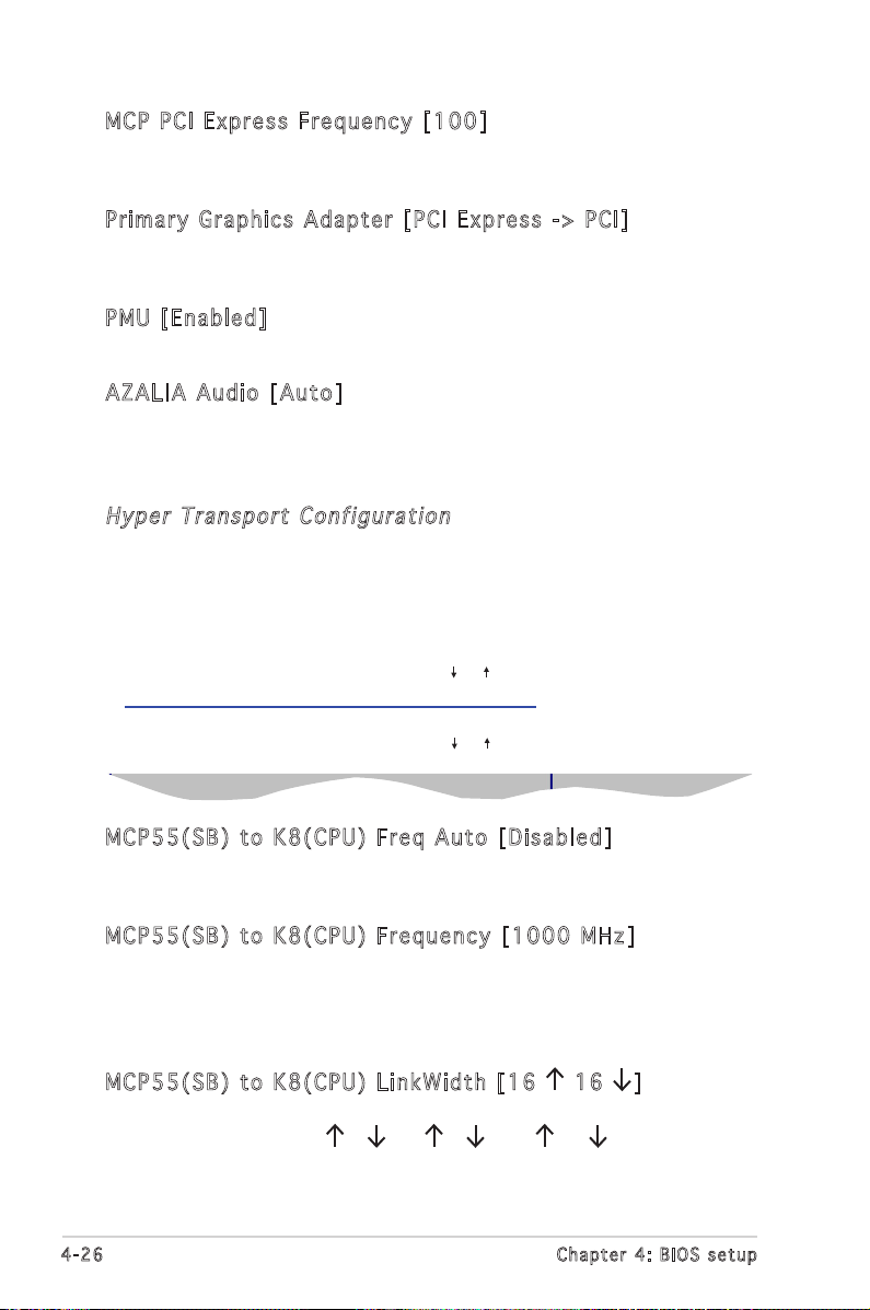
MCP PC I Ex p re s s F r eq u enc y [ 1 00]
Allows you to set the PCI Express frequency.
Conguration options: [100] [101]...[200]
Pri m ar y Gr a ph i cs A da p ter [P C I E x pr e ss - > P CI]
Allows you to select the primary graphics adapter.
Conguration options: [PCI Express -> PCI] [PCI -> PCI Express]
PMU [E n abl e d]
Conguration options: [Disabled] [Enabled]
AZA L IA Aud i o [ Aut o ]
Allows you to enable or disable the Azalia audio CODEC.
Conguration options: [Auto] [Disabled]
Hyp e r T ra n spo rt C on f ig u rat ion
The sub-menu allows you to change the Hyper Transport settings.
Hyper Transport MCP55 Conguration
MCP55(SB) to K8(CPU) Freq Auto [Disabled]
MCP55(SB) to K8(CPU) Frequency [1000 MHZ]
MCP55(SB) to K8(CPU) LinkWidth [16 16 ]
Hyper Transport I055 Conguration
I055 (Slave) to K8 (CPU) Freq Au [Disabled]
I055 (Slave) to K8 (CPU) Frequen [1000 MHz]
I055 (Slave) to K8 (CPU) LinkWid [16 16 ]
MCP55(SB) to K8(CPU)
frequency selection
by CPU capability
MCP 5 5(S B) t o K 8(C P U) F re q Au t o [ Dis a bl e d]
Enables or disables the CPU to automatically adjust Hyper Transport
frequency. Conguration options: [Disabled] [Enabled]
MCP 5 5(S B) t o K 8(C P U) F re q uen c y [ 100 0 M H z]
Allows you to set the Hyper Transport frequency. This item appears when
you set the MCP55(SB) to K8(CPU) Freq Auto to Disabled.
Conguration options: [200 MHz] [400 MHz] [600 MHz] [800 MHz]
[1000 MHz].
MCP 5 5(S B) t o K 8(C P U) L in k Wid t h [ 16 1 6 ]
Sets the Hyper Transport width.
Conguration options: [4 4 ] [8 8 ] [16 16 ]
4-26 Ch a p t e r 4 : B I O S s e t u p
Page 87

Select Screen
Select Item
+- Change Option
F1 General Help
F10 Save and Exit
ESC Exit
IO5 5 (Sl ave ) to K8 ( CPU ) F r eq A u [ Dis a bl e d]
Enables or disables the frequency selection by CPU capability.
Conguration options: [Disabled] [Auto]
IO5 5 (Sl ave ) to K8 ( CPU ) F r eq [ 10 0 0 M H z]
Allows you to select the frequency.
Conguration options: [200 MHz] [400 MHz] [600 MHz] [800 MHz]
[1000 MHz].
IO5 5 (Sl ave ) to K8 ( CPU ) L i nkw i d [ 16 1 6 ]
Allows you to select the width.
Conguration options: [4 4 ] [8 8 ] [16 16 ]
I05 5 B r id g e C onf i gu r at i on
The sub-menu allows you to change the I055 Bridge settings.
I055 Bridge Conguration
I055 TRIM [Disabled]
I055 PMU [Disabled]
Options
Enabled
Disabled
I05 5 TR IM [ Dis abl e d]
Enables or disables the I055 TRIM.
Conguration options: [Auto] [Disabled]
I05 5 PM U [ D isa b le d ]
Enables or disables the I055 PMU.
Conguration options: [Auto] [Disabled]
ASUS KFN32-D SLI Series 4-27
Page 88

Select Screen
Select Item
+- Change Option
F1 General Help
F10 Save and Exit
ESC Exit
Int e l P CI - X H ub C on f ig u rat ion
The sub-menu allows you to change the Intel PCI-X Hub settings.
Congure advance settings for PCI-X Hub
PCI Bus Frequency [Auto]
I/O Port Decode [4K Decode]
RAS Sticky Error Handling [Clear Errors]
VGA 16-Bit Decode [Enabled]
This question will
allow to select the
maximum PCI bus speed
to be programmed.
Default will always
be set to AUTO where
bus speed will be
decided based on the
capabilities of the
device on that bus.
PCI Bu s Fr e qu e ncy [A u to]
Allows you to set the PCI Bus frequency.
Conguration options: [Auto] [33 Mhz PCI] [66 Mhz PCI] [66 Mhz PCI-X
M1] [100 Mhz PCI-X M1] [133 Mhz PCI-X M1] [66 Mhz PCI-X M2] [100
Mhz PCI-X M2] [133 Mhz PCI-X M2]
I/O Po r t D e co d e [ 4 K D eco d e]
Allows you to set the I/O Port Decode. Conguration options: [4K Decode]
[1K Decode]
RAS St i cky Er r or H an d lin g [ C lea r E r ror s ]
Allows you to set the RAS Sticky Error Handling. Conguration options:
[Clear Errors] [Leave Errors]
VGA 16- Bit Dec ode [Di sab l ed]
Enables or disables the VGA 16-Bit Decode.
Conguration options: [Disabled] [Enabled]
4-28 Ch a p t e r 4 : B I O S s e t u p
Page 89

4.4 .5 Onb oar d De vic es C onf ig ur ati on
Congure Win627THF Super IO Chipset
Serial Port1 Address [3F8/IRQ4]
Parallel Port Address [378]
Parallel Port Model [Normal]
Parallel Port IRQ [IRQ7]
Onboard Game/Midi Port [Disabled]
Congure Onboard Device
Onboard BCM5754 Lan [Enabled]
Onboard LAN Boot ROM [Disabled]
Onboard T43AB22A 1394 [Enabled]
Onboard LSI SAS1068 [Enabled]
Allows BIOS to Select
Serial Port1 Base
Addresses.
Ser i al Por t 1 A ddr e ss [3F 8 /IR Q4]
Allows you to select the Serial Port1 base address.
Conguration options: [Disabled] [3F8/IRQ4] [2F8/IRQ3] [3E8/IRQ4]
[2E8/IRQ3]
Par a ll e l P o rt Add r es s [3 7 8]
Allows you to select the Parallel Port base addresses.
Conguration options: [Disabled] [378] [278] [3BC]
The following items appear when the Parallel Port Address is enabled.
Par a ll e l P o rt Mod e [ N orm a l]
Allows you to select the Parallel Port mode.
Conguration options: [Normal] [Bi-Directional] [EPP] [ECP]
The following item appears when the Parallel Port Mode is set to EPP.
EPP V e rsion [ 1 .9]
Allows you to select the Parallel Port EPP version.
Conguration options: [1.9] [1.7]
The following item appears when the Parallel Port Mode is set to ECP.
ECP M o d e DM A C h anne l [ D MA3]
Allows you to select the Parallel Port ECP DMA.
Conguration options: [DMA0] [DMA1] [DMA3]
Parallel Port IRQ [IRQ7]
Allows you to set the Parallel Port IRQ.
Conguration options: [IRQ5] [IRQ7]
ASUS KFN32-D SLI Series 4-29
Page 90

Onb o ar d Ga m e/ M idi Po r t [ D is a ble d ]
Select Screen
Select Item
+- Change Option
F1 General Help
F10 Save and Exit
ESC Exit
Enables or disables the Onboard Game/Midi Port.
Conguration options: [Disabled] [200/300] [200/330] [208/300]
[208/330]
Onb o ar d BC M 575 4 L A N [ E na b led ]
Enables or disables the Onboard BCM5754 LAN.
Conguration options: [Disabled] [200/300] [208/300] [208/330]
Onboard LAN Boot ROM [Disabled]
Allows you to enable or disable the option ROM in the onboard LAN
controller. Conguration options: [Disabled] [Enabled]
Onb o ar d T4 3 AB2 2A 1 394 [E n abl e d]
Enables or disables the 1394 controller T43AB22A.
Conguration options: [Disabled] [Enabled]
Onb o ar d LS I S A S10 6 8 [ E na b led ]
Enables or disables the Onboard LSI SAS1068.
Conguration options: [Disabled] [Enabled]
4.4 .6 PCI Pn P
The PCI PnP menu items allow you to change the advanced settings for
PCI/PnP devices. The menu includes setting IRQ and DMA channel resources
for either PCI/PnP or legacy ISA devices, and setting the memory size block
for legacy ISA devices.
Take caution when changing the settings of the PCI PnP menu items.
Incorrect eld values can cause the system to malfunction.
Advanced PCI/PnP Settings
WARNING: Setting wrong values in below sections
may cause system to malfunction.
Plug And Play O/S [No]
PCI Latency Timer [64]
Allocate IRQ to PCI VGA [Yes]
Palette Snooping [Disabled]
IRQ-3 assigned to [PCI Device]
IRQ-4 assigned to [PCI Device]
IRQ-5 assigned to [PCI Device]
IRQ-7 assigned to [PCI Device]
IRQ-9 assigned to [PCI Device]
IRQ-10 assigned to [PCI Device]
IRQ-11 assigned to [PCI Device]
IRQ-14 assigned to [PCI Device]
IRQ-15 assigned to [PCI Device]
4-30 Ch a p t e r 4 : B I O S s e t u p
NO: Lets the BIOS
congue all the
devices in the system.
YES: Lets the
operating system
congure Plug and Play
(PnP) devices not
required for boot if
your system has a Plug
and Play operating
system.
Page 91

Plu g A n d P l ay O/S [N o ]
When set to [No], BIOS congures all the devices in the system. When set
to [Yes] and if you install a Plug and Play operating system, the operating
system congures the Plug and Play devices not required for boot.
Conguration options: [No] [Yes]
PCI La t enc y T i mer [6 4 ]
Allows you to select the value in units of PCI clocks for the PCI device
latency timer register. Conguration options: [32] [64] [96] [128] [160]
[192] [224] [248]
All o ca t e I R Q t o P C I V GA [ Ye s ]
When set to [Yes], BIOS assigns an IRQ to PCI VGA card if the card
requests for an IRQ. When set to [No], BIOS does not assign an IRQ to the
PCI VGA card even if requested. Conguration options: [No] [Yes]
Pal e tt e Sn o op i ng [ Di s abl e d]
When set to [Enabled], the pallete snooping feature informs the PCI
devices that an ISA graphics device is installed in the system so that the
latter can function correctly. Conguration options: [Disabled] [Enabled]
IRQ - xx ass i gn e d t o [ P CI D ev i ce]
When set to [PCI Device], the specic IRQ is free for use of PCI/PnP
devices. When set to [Reserved], the IRQ is reserved for legacy ISA
devices. Conguration options: [PCI Device] [Reserved]
4.4 .7 MPS Co nf ig ura ti on
The items in this menu allows you to congure the Multi-Processor Table.
Select an item then press <Enter> to display the conguration options.
MPS Conguration
MPS Revision [1.4]
MPS Re v isi o n [ 1.4 ]
Allows you to select the multi-processor system revision.
Conguration options: [1.1] [1.4]
ASUS KFN32-D SLI Series 4-31
Select MPS Revision.
Page 92

4.4 .8 USB Co nf ig u ra ti on
The items in this menu allows you to change the USB-related features.
Select an item then press <Enter> to display the conguration options.
USB Conguration
Module Version - 2.24.0-11.4
USB Devices Enabled: None
USB 1.1 Controller [Enabled]
USB 2.0 Controller [Enabled]
Legacy USB Support [Enabled]
USB 2.0 Controller Mode [HiSpeed]
BIOS EHCI Hand-Off [Enabled]
The Module Version and USB Devices Enabled items show the
auto-detected values. If no USB device is detected, the USB Devices
Enabled item shows None.
Enables USB host
controllers.
USB 1.1 Co n tro lle r [E nab l ed]
Enables or disables the USB 1.1 Controller.
Conguration options: [Disabled] [Enabled]
USB 2.0 Co n tro lle r [E nab l ed]
Enables or disables the USB 2.0 Controller.
Conguration options: [Disabled] [Enabled]
Leg a cy USB Su p por t [ E nab l ed ]
Allows you to enable or disable support for legacy USB devices. Setting
to [Auto] allows the system to detect the presence of USB devices at
startup. If detected, the USB controller legacy mode is enabled. If no USB
device is detected, the legacy USB support is disabled.
Conguration options: [Disabled] [Enabled] [Auto]
USB 2.0 Co n tro lle r Mo de [ HiS pee d ]
Allows you to set the USB 2.0 controller mode to HiSpeed (480 Mbps) or
FullSpeed (12 Mbps). Conguration options: [HiSpeed ] [FullSpeed ]
BIO S E H CI H an d -Of f [ E nab l ed ]
Enables or disables the BIOS EHCI hand-off feature.
Conguration options: [Enabled] [Disabled]
4-32 Ch a p t e r 4 : B I O S s e t u p
Page 93

4.5 Power menu
The Power menu items allow you to change the settings for the ACPI and
Advanced Power Management (APM) features. Select an item then press
<Enter> to display the conguration options.
ACPI MCFG Support [Enabled]
ACPI APIC Support [Enabled]
APM Conguration
Hardware Monitor
Enabled, BIOS will
report ACPI MCFG
Table.
Disabled, BIOS
doesn’t report.
4.5 .1 ACP I M CF G Sup po rt [E na bl ed]
Allows you to enable or disable the Memory Mapped Conguration (MCFG)
support. When set to Enabled, the MCFG table pointer is included in the
RSDT pointer list. Conguration options: [Disabled] [Enabled]
Set the ACPI MCFG Support to Disable, when you install RedHat AS4.0 UP2
64 bit, Fedora Core 3 64 bit, Fedora Core 4 64 bit operation system, and
4 GB memory.
4.5 .2 ACP I A PI C Sup po rt [E na bl ed]
Allows you to enable or disable the Advanced Conguration and Power
Interface (ACPI) support in the Application-Specic Integrated Circuit
(ASIC). When set to Enabled, the ACPI APIC table pointer is included in the
RSDT pointer list. Conguration options: [Disabled] [Enabled]
Do not change the ACPI APIC support after you have installed the
operating system (OS), otherwise, a boot failure may occur.
ASUS KFN32-D SLI Series 4-33
Page 94

4.5 .3 APM Co nf ig ura ti on
Power Management/APM [Enabled]
Power Button Mode [On/Off]
Force Throttle [Disabled]
Manual Throttle Ratio [50%]
System Thermal [Disabled]
Thermal throttle Ratio [50%]
Resume on PME# [Disabled]
Resume on Ring [Disabled]
Resume on PS/2 Keyboard [Disabled]
Resume On PS/2 Mouse [Disabled]
Resume On RTC Alarm [Disabled]
Restore On AC Power Loss [Power Off]
<Enter> to select
whether or not to
restart the system
after AC power loss.
Pow e r M ana g em e nt/ A PM [En a bl e d]
Allows you to enable or disable the motherboard Advance Power
Management (APM) feature. Conguration options: [Enabled] [Disabled]
Pow e r B utt o n M ode [O n /Of f ]
Allows the system to go into On/Off mode or suspend mode when the
power button is pressed. Conguration options: [On/Off] [Suspend]
For c e T hro t tl e [D i sa b led ]
Enables or disables the force to thermal throttling function. Conguration
options: [Disabled] [Enabled]
Man u al Thr o tt l e R a ti o [5 0 %]
Selects the duty cycle in throttle mode. Conguration options: [87.5%]
[75.0%] [62.5%] [50%] [37.5%] [25%] [12.5%]
Sys t em The r ma l [D i sa b led ]
Enables or disables thermal to generate a power management event.
Conguration options: [Disabled] [Enabled]
The r ma l Th r ot t le R at i o [ 5 0%]
Selects the duty cycle in throttle mode when the thermal override
condition occurs. Conguration options: [87.5%] [75.0%] [62.5%] [50%]
[37.5%] [25%] [12.5%]
4-34 Ch a p t e r 4 : B I O S s e t u p
Page 95

Res u me on P ME # [E n ab l ed]
When set to [Enabled], the system enables the PME to generate a wake
event while the computer is in Soft-off mode.
Conguration options: [Disabled] [Enabled]
Res u me On R in g [D i sa b led ]
Allows you to enable or disable the RI to generate a wake event.
Conguration options: [Disabled] [Enabled]
Res u me On P S/ 2 Ke y bo a rd [ Di s abl e d]
Allows you to disable or enable the PS/2 Power-On by keyboard feature.
This feature requires an ATX power supply that provides at least 1A on the
+5VSB lead. Conguration options: [Disabled] [Enabled]
Scroll down the screen to display the following items.
Res u me On P S/ 2 Mo u se [Di s ab l ed]
When set to [Enabled], this parameter allows you to use the PS/2 mouse
to turn on the system. This feature requires an ATX power supply that
provides at least 1A on the +5VSB lead.
Conguration options: [Disabled] [Enabled]
Res t or e on AC Pow e r L oss [P o wer Of f ]
When set to Power Off, the system goes into off state after an AC power
loss. When set to Power On, the system goes on after an AC power loss.
When set to Last State, the system goes into either off or on state,
whatever the system was before the AC power loss.
Conguration options: [Disabled] [Enabled]
ASUS KFN32-D SLI Series 4-35
Page 96

4.5 .6 Har dwa re M oni to r
Hardware Monitor
CPU1 Temperature [38ºC/100ºF]
CPU2 Temperature [41ºC/105.5ºF]
MB Temperature [47ºC/114ºF]
CPU Fan1 Speed [3884RPM]
CPU Fan2 Speed [3648RPM]
Front Fan1 Speed [1917RPM]
Front Fan2 Speed [N/A]
Rear Fan1 Speed [N/A]
Rear Fan2 Speed [N/A]
Smart Fan Control [Enabled]
VCORE1 Voltage [ 1.320V]
VCORE2 Voltage [ 1.320V]
3.3V Voltage [ 3.345V]
CPU1 Temperature
Use the arrow down key to display additional items.
5V Voltage [ 5.094V]
5VSB Voltage [ 4.980V]
VBAT Voltage [ 3.120V]
12V Voltage [12.053V]
CPU 1 /CP U2 T emp e ra t ure [x x xºC / xx x ºF]
MB T em p era t ur e [x x xº C /xx x ºF ]
The onboard hardware monitor automatically detects and displays the
motherboard and CPU temperatures. Select [Ignored] if you do not wish to
display the detected temperatures.
CPU Fa n 1/F a n2 Spe e d [ xxx x RPM ] o r [I gno r ed]
Fro n t F an1 / Fa n 2 S p eed [x x xxR PM] or [Ig n ore d]
Rea r F an1 / Fa n 2 S p ee d [x x xx R PM] or [Ig n or e d]
The onboard hardware monitor automatically detects and displays the CPU,
front, and rear fan speed in rotations per minute (RPM). If the fan is not
connected to the motherboard, the eld shows N/A. Select [Ignored] if you
do not wish to display the detected temperatures.
Sma r t F an C on t rol [E n abl e d]
Allows you to enable or disable the ASUS Smart Fan feature that smartly
adjusts the fan speeds for more efcient system operation. Conguration
options: [Disabled] [Enabled]
VCO R E1 Vol t ag e , V C OR E 2 V o lt a ge, 3.3 V V o lta ge, 5V
Vol t ag e , 5 V SB Vol t ag e , V B AT Vol t ag e , 1 2 V V olt a ge
The onboard hardware monitor automatically detects the voltage output
through the onboard voltage regulators.
4-36 Ch a p t e r 4 : B I O S s e t u p
Page 97

4.6 Boot menu
Select Screen
Select Item
Enter Go to Sub-screen
F1 General Help
F10 Save and Exit
ESC Exit
Select Screen
Select Item
Enter Go to Sub-screen
F1 General Help
F10 Save and Exit
ESC Exit
The Boot menu items allow you to change the system boot options. Select
an item then press <Enter> to display the sub-menu.
APM Conguration
Boot Device Priority
Boot Settings Conguration
Security
4.6 .1 Boo t D ev ic e P ri or ity
Boot Device Priority
1st Boot Device [1st FLOPPY DRIVE]
2nd Boot Device [PM-ST330620A]
3rd Boot Device [PS-ASUS CD-S360]
Species the boot
sequence from the
available devices.
A device enclosed
in parenthesis has
been disabled in the
corresponding type
menu.
1st ~ x xth Boo t D e vic e [ 1 st Flo p py Dri v e]
These items specify the boot device priority sequence from the available
devices. The number of device items that appears on the screen depends
on the number of devices installed in the system.
Conguration options: [xxxxx Drive] [Disabled]
ASUS KFN32-D SLI Series 4-37
Page 98

4.6 .2 Boo t S et ti ngs C on fig ur at ion
Boot Settings Conguration
Quick Boot [Enabled]
Full Screen Logo [Enabled]
AddOn ROM Display Mode [Force BIOS]
Bootup Num-Lock [On]
PS/2 Mouse Support [Auto]
Wait For ‘F1’ If Error [Enabled]
Hit ‘DEL’ Message Display [Enabled]
Interrupt 19 Capture [Disabled]
Allows BIOS to skip
certain tests while
booting. This will
decrease the time
needed to boot the
system.
Qui c k B oot [E n abl e d]
Enabling this item allows the BIOS to skip some power on self tests (POST)
while booting to decrease the time needed to boot the system. When set
to [Disabled], BIOS performs all the POST items.
Conguration options: [Disabled] [Enabled]
Ful l S c ree n L o go [ En a ble d ]
Allows you to enable or disable the full screen logo display feature.
Conguration options: [Disabled] [Enabled]
Set this item to [Enabled] to use the ASUS MyLogo2™ feature.
Add On ROM Di s pla y M o de [ Fo r ce B IO S ]
Sets the display mode for option ROM.
Conguration options: [Force BIOS] [Keep Current]
Boo t up Num - Lo c k [ O n]
Allows you to select the power-on state for the NumLock.
Conguration options: [Off] [On]
PS/ 2 M o use Su p por t [ A uto ]
Allows you to enable or disable support for PS/2 mouse.
Conguration options: [Disabled] [Enabled] [Auto]
Wai t f o r ‘ F 1’ If E rr o r [ E na b led ]
When set to Enabled, the system waits for the F1 key to be pressed when
error occurs. Conguration options: [Disabled] [Enabled]
Hit ‘D E L’ M es s age Di s pla y [ E nab l ed ]
When set to Enabled, the system displays the message “Press DEL to run
Setup” during POST. Conguration options: [Disabled] [Enabled]
4-38 Ch a p t e r 4 : B I O S s e t u p
Page 99

Int e rr u pt 1 9 C apt u re [Di s abl ed]
Select Screen
Select Item
+- Change Option
F1 General Help
F10 Save and Exit
ESC Exit
When set to [Enabled], this function allows the option ROMs to trap
Interrupt 19. Conguration options: [Disabled] [Enabled]
4.6 .3 Sec uri ty
The Security menu items allow you to change the system security settings.
Select an item then press <Enter> to display the conguration options.
Security Settings
Supervisor Password : Not Installed
User Password : Not Installed
Change Supervisor Password
Change User Passward
<Enter> to change
password.
<Enter> again to
disabled password.
Cha n ge Sup e rv i sor Pa s swo r d
Select this item to set or change the supervisor password. The Supervisor
Password item on top of the screen shows the default Not Installed. After
you set a password, this item shows Installed.
To set a Supervisor Password:
1. Select the Change Supervisor Password item, then press <Enter>.
2. From the password box, type a password composed of at least six
letters and/or numbers, then press <Enter>.
3. Conrm the password when prompted.
The message “Password Installed” appears after you successfully set your
password.
To change the supervisor password, follow the same steps as in setting a
user password.
To clear the supervisor password, select the Change Supervisor Password
then press <Enter>. The message “Password Uninstalled” appears.
If you forget your BIOS password, you can clear it by erasing the CMOS
Real Time Clock (RTC) RAM. See section “2.6 Jumpers” for information
on how to erase the RTC RAM.
ASUS KFN32-D SLI Series 4-39
Page 100

After you have set a supervisor password, the other items appear to allow
you to change other security settings.
Boot
Security Settings
Supervisor Password : Not Installed
User Password : Not Installed
Change Supervisor Password
User Access Level [Full Access]
Change User Password
Clear User Password
Password Check [Setup]
v02.58 (C)Copyright 1985-2002, American Megatrends, Inc.
BIOS SETUP UTILITY
<Enter> to change
password.
<Enter> again to
disabled password.
Select Screen
Select Item
Enter Change
F1 General Help
F10 Save and Exit
ESC Exit
Use r A c ces s L e vel [F u ll A cc e ss]
This item allows you to select the access restriction to the Setup items.
Conguration options: [No Access] [View Only] [Limited] [Full Access]
No Access prevents user access to the Setup utility.
View Only allows access but does not allow change to any eld.
Limited allows changes only to selected elds, such as Date and Time.
Full Access allows viewing and changing all the elds in the Setup
utility.
Cha n ge Use r P a ssw o rd
Select this item to set or change the user password. The User Password
item on top of the screen shows the default Not Installed. After you set a
password, this item shows Installed.
To set a User Password:
1. Select the Change User Password item and press <Enter>.
2. On the password box that appears, type a password composed of at
least six letters and/or numbers, then press <Enter>.
3. Conrm the password when prompted.
The message “Password Installed” appears after you set your password
successfully.
To change the user password, follow the same steps as in setting a user
password.
4-40 Ch a p t e r 4 : B I O S s e t u p
 Loading...