

Asus K8N-E Deluxe User Manual

K8N-E
Deluxe
User Guide
Motherboard

Checklist
E1581
First Edition
June 2004
Copyright © 2004 ASUSTeK COMPUTER INC. All Rights Reserved.
No part of this manual, including the products and software described in it, may be
reproduced, transmitted, transcribed, stored in a retrieval system, or translated into any
language in any form or by any means, except documentation kept by the purchaser for
backup purposes, without the express written permission of ASUSTeK COMPUTER INC.
(“ASUS”).
Product warranty or service will not be extended if: (1) the product is repaired, modified or
altered, unless such repair, modification of alteration is authorized in writing by ASUS; or (2)
the serial number of the product is defaced or missing.
ASUS PROVIDES THIS MANUAL “AS IS” WITHOUT WARRANTY OF ANY KIND, EITHER
EXPRESS OR IMPLIED, INCLUDING BUT NOT LIMITED TO THE IMPLIED WARRANTIES
OR CONDITIONS OF MERCHANTABILITY OR FITNESS FOR A PARTICULAR PURPOSE.
IN NO EVENT SHALL ASUS, ITS DIRECTORS, OFFICERS, EMPLOYEES OR AGENTS BE
LIABLE FOR ANY INDIRECT, SPECIAL, INCIDENTAL, OR CONSEQUENTIAL DAMAGES
(INCLUDING DAMAGES FOR LOSS OF PROFITS, LOSS OF BUSINESS, LOSS OF USE
OR DATA, INTERRUPTION OF BUSINESS AND THE LIKE), EVEN IF ASUS HAS BEEN
ADVISED OF THE POSSIBILITY OF SUCH DAMAGES ARISING FROM ANY DEFECT OR
ERROR IN THIS MANUAL OR PRODUCT.
SPECIFICATIONS AND INFORMATION CONTAINED IN THIS MANUAL ARE FURNISHED
FOR INFORMATIONAL USE ONLY, AND ARE SUBJECT TO CHANGE AT ANY TIME
WITHOUT NOTICE, AND SHOULD NOT BE CONSTRUED AS A COMMITMENT BY ASUS.
ASUS ASSUMES NO RESPONSIBILITY OR LIABILITY FOR ANY ERRORS OR
INACCURACIES THAT MAY APPEAR IN THIS MANUAL, INCLUDING THE PRODUCTS
AND SOFTWARE DESCRIBED IN IT.
Products and corporate names appearing in this manual may or may not be registered
trademarks or copyrights of their respective companies, and are used only for identification or
explanation and to the owners’ benefit, without intent to infringe.
ii

Contents
Notices .......................................................................................... vii
Safety information ........................................................................ viii
About this guide.............................................................................. ix
How this guide is organized ..................................................ix
Where to find more information ............................................. ix
Conventions used in this guide ..............................................x
Typography.............................................................................x
K8N-E Deluxe specifications summary .......................................... xi
Chapter 1: Product introduction
1.1 Welcome! ........................................................................... 1-1
1.2 Package contents............................................................... 1-1
1.3 Special features.................................................................. 1-2
1.3.1 Product Highlights.................................................. 1-2
1.3.2 Unique ASUS features ........................................... 1-4
Features
Chapter 2: Hardware information
2.1 Before you proceed ............................................................ 2-1
2.2 Motherboard overview........................................................ 2-2
2.2.1 Placement direction ............................................... 2-2
2.2.2 Screw holes ........................................................... 2-2
2.2.3 Motherboard layout ................................................ 2-3
2.2.4 Layout Contents..................................................... 2-4
2.3 Central Processing Unit (CPU)........................................... 2-6
2.3.1 Overview ................................................................ 2-6
2.3.2 Installing the CPU .................................................. 2-6
2.3.3 Installing the heatsink and fan ............................... 2-8
2.3.4 Connecting the CPU fan cable ............................ 2-10
2.3.5 CPU heatsink and fan Qualified Vendors List ...... 2-10
2.4 System memory ................................................................2-11
2.4.1 Overview ...............................................................2-11
2.4.2 Memory configurations .........................................2-11
2.4.3 Installing a DIMM ................................................. 2-13
2.4.4 Removing a DIMM ............................................... 2-13
2.5 Expansion slots ................................................................ 2-14
2.5.1 Installing an expansion card ................................ 2-14
2.5.2 Configuring an expansion card ............................ 2-14
iii

Contents
Safeguards
2.5.3 Interrupt assignments .......................................... 2-15
2.5.4 PCI slots .............................................................. 2-16
2.5.5 AGP slot............................................................... 2-16
2.6 Jumpers............................................................................ 2-17
2.7 Connectors ....................................................................... 2-19
2.7.1 Rear panel connectors......................................... 2-19
2.7.2 Internal connectors .............................................. 2-20
Chapter 3: Powering up
3.1 Starting up for the first time ................................................ 3-1
3.2 Powering off the computer ................................................. 3-2
3.2.1 Using the OS shut down function .......................... 3-2
3.2.2 Using the dual-function power switch .................... 3-2
3.3 ASUS POST Reporter™ .................................................... 3-3
3.3.1 Vocal POST messages .......................................... 3-3
3.3.2 Winbond Voice Editor ............................................ 3-5
Chapter 4: BIOS setup
4.1 Managing and updating your BIOS .................................... 4-1
4.1.1 Creating a bootable floppy disk ............................. 4-1
4.1.2 Using AFUDOS to update the BIOS ...................... 4-2
4.1.3 Using AFUDOS to copy BIOS from PC ................. 4-3
4.1.4 Using ASUS EZ Flash to update the BIOS ............ 4-4
4.1.5 Recovering the BIOS with CrashFree BIOS 2 ....... 4-5
4.1.6 ASUS Update ........................................................ 4-7
4.2 BIOS Setup program .......................................................... 4-9
4.2.1 BIOS menu screen .............................................. 4-10
4.2.2 Menu bar.............................................................. 4-10
4.2.3 Navigation keys ................................................... 4-10
4.2.4 Menu items ...........................................................4-11
4.2.5 Sub-menu items....................................................4-11
4.2.6 Configuration fields ...............................................4-11
4.2.7 Pop-up window .....................................................4-11
4.2.8 Scroll bar...............................................................4-11
4.2.9 General help .........................................................4-11
iv
4.3 Main menu........................................................................ 4-12
4.3.1 System Time ........................................................ 4-12
4.3.2 System Date ........................................................ 4-12

Contents
4.3.3 Legacy Diskette A ................................................ 4-12
4.3.4 Language............................................................. 4-12
4.3.5 Primary and Secondary IDE Master/Slave .......... 4-13
4.3.6 System Information .............................................. 4-14
4.4 Advanced menu ............................................................... 4-15
4.4.1 Instant Music Configuration ................................. 4-15
4.4.2 JumperFree Configuration ................................... 4-16
4.4.3 Speech Configuration .......................................... 4-17
4.4.4 CPU Configuration ............................................... 4-18
4.4.5 Chipset................................................................. 4-19
4.4.6 Onboard Devices Configuration........................... 4-23
4.4.7 PCI PnP ............................................................... 4-25
4.5 Power menu ..................................................................... 4-27
4.5.1 Suspend Mode..................................................... 4-27
4.5.2 Repost Video on S3 Resume............................... 4-27
4.5.3 ACPI 2.0 Support ................................................. 4-27
4.5.4 ACPI APIC Support.............................................. 4-27
4.5.5 APM Configuration............................................... 4-28
4.5.6 Hardware Monitor ................................................ 4-29
4.6 Boot menu ........................................................................ 4-31
4.6.1 Boot Device Priority ............................................. 4-31
4.6.2 Hard Disk Drives .................................................. 4-32
4.6.3 Boot Settings Configuration ................................. 4-32
4.6.4 Security ................................................................ 4-33
4.7 Exit menu ......................................................................... 4-36
Chapter 5: Software support
5.1 Installing an operating system............................................ 5-1
5.2 Support CD information...................................................... 5-1
5.2.1 Running the support CD ........................................ 5-1
5.2.2 Drivers menu ......................................................... 5-2
5.2.3 Utilities menu ......................................................... 5-3
5.2.4 Manuals menu ....................................................... 5-5
5.2.5 ASUS Contact information ..................................... 5-6
5.2.6 Other information ................................................... 5-6
5.3 Software Information .......................................................... 5-9
5.3.1 ASUS MyLogo2™.................................................. 5-9
5.3.2 ASUS Instant Music ..............................................5-11
v

Contents
5.4 Audio configurations......................................................... 5-13
5.4.1 Sound Effect options............................................ 5-14
5.4.2 S/PDIF options..................................................... 5-14
5.4.3 Speaker Configuration ......................................... 5-15
5.4.4 AI Audio feature ................................................... 5-16
5.4.5 HRTF Demo......................................................... 5-17
5.4.6 General settings................................................... 5-18
5.4.7 Rear panel audio ports function variation ............ 5-18
5.5 RAID configurations ......................................................... 5-19
5.5.1 Installing hard disks ............................................. 5-20
®
5.5.2 NVIDIA
5.5.3 Silicon Image RAID configurations ...................... 5-22
5.6 Creating a RAID driver disk.............................................. 5-23
5.7 Cool ‘n’ Quiet!™ Technology ............................................ 5-24
5.7.1 Enabling Cool ‘n’ Quiet!™ Technology................. 5-24
5.7.2 Launching the Cool ‘n’ Quiet!™ software............. 5-26
RAID configurations .............................. 5-21
vi

Notices
Federal Communications Commission Statement
This device complies with Part 15 of the FCC Rules. Operation is subject to
the following two conditions:
• This device may not cause harmful interference, and
• This device must accept any interference received including interference
that may cause undesired operation.
This equipment has been tested and found to comply with the limits for a
Class B digital device, pursuant to Part 15 of the FCC Rules. These limits
are designed to provide reasonable protection against harmful interference
in a residential installation. This equipment generates, uses and can radiate
radio frequency energy and, if not installed and used in accordance with
manufacturer’s instructions, may cause harmful interference to radio
communications. However, there is no guarantee that interference will not
occur in a particular installation. If this equipment does cause harmful
interference to radio or television reception, which can be determined by
turning the equipment off and on, the user is encouraged to try to correct the
interference by one or more of the following measures:
• Reorient or relocate the receiving antenna.
• Increase the separation between the equipment and receiver.
• Connect the equipment to an outlet on a circuit different from that to
which the receiver is connected.
• Consult the dealer or an experienced radio/TV technician for help.
The use of shielded cables for connection of the monitor to the
graphics card is required to assure compliance with FCC regulations.
Changes or modifications to this unit not expressly approved by the
party responsible for compliance could void the user’s authority to
operate this equipment.
Canadian Department of Communications Statement
This digital apparatus does not exceed the Class B limits for radio noise
emissions from digital apparatus set out in the Radio Interference
Regulations of the Canadian Department of Communications.
This class B digital apparatus complies with Canadian ICES-003.
vii

Safety information
Electrical safety
•To prevent electrical shock hazard, disconnect the power cable from the
electrical outlet before relocating the system.
• When adding or removing devices to or from the system, ensure that the
power cables for the devices are unplugged before the signal cables are
connected. If possible, disconnect all power cables from the existing
system before you add a device.
• Before connecting or removing signal cables from the motherboard,
ensure that all power cables are unplugged.
• Seek professional assistance before using an adapter or extension cord.
These devices could interrupt the grounding circuit.
• Make sure that your power supply is set to the correct voltage in your
area. If you are not sure about the voltage of the electrical outlet you are
using, contact your local power company.
• If the power supply is broken, do not try to fix it by yourself. Contact a
qualified service technician or your retailer.
Operation safety
• Before installing the motherboard and adding devices on it, carefully read
all the manuals that came with the package.
• Before using the product, make sure all cables are correctly connected
and the power cables are not damaged. If you detect any damage,
contact your dealer immediately.
•To avoid short circuits, keep paper clips, screws, and staples away from
connectors, slots, sockets and circuitry.
•Avoid dust, humidity, and temperature extremes. Do not place the
product in any area where it may become wet.
• Place the product on a stable surface.
• If you encounter technical problems with the product, contact a qualified
service technician or your retailer.
viii

About this guide
This user guide contains the information you need when installing the
motherboard.
How this guide is organized
This manual contains the following parts:
• Chapter 1: Product introduction
This chapter describes the motherboard features and the new
technologies it supports.
• Chapter 2: Hardware information
This chapter lists the hardware setup procedures that you have to
perform when installing system components. It includes description of
the jumpers and connectors on the motherboard.
• Chapter 3: Powering up
This chapter describes the power up sequence, the vocal POST
messages, and ways of shutting down the system.
• Chapter 4: BIOS setup
This chapter tells how to change system settings through the BIOS
Setup menus. Detailed descriptions of the BIOS parameters are also
provided.
• Chapter 5: Software support
This chapter describes the contents of the support CD that comes with
the motherboard package.
Where to find more information
Refer to the following sources for additional information and for product
and software updates.
1. ASUS websites
The ASUS website provides updated information on ASUS hardware
and software products. Refer to the ASUS contact information.
2. Optional documentation
Your product package may include optional documentation, such as
warranty flyers, that may have been added by your dealer. These
documents are not part of the standard package.
ix
Conventions used in this guide
To make sure that you perform certain tasks properly, take note of the
following symbols used throughout this manual.
DANGER/WARNING: Information to prevent injury to yourself
when trying to complete a task.
CAUTION: Information to prevent damage to the components
when trying to complete a task.
IMPORTANT: Information that you MUST follow to complete a
task.
NOTE: Tips and additional information to aid in completing a task.
Typography
Bold text Indicates a menu or an item to select.
Italics Used to emphasize a word or a phrase.
<Key> Keys enclosed in the less-than and greater-than
sign indicates that you must press the enclosed
key. Example: <Enter> indicates that you must
press the Enter or Return key.
<Multiple key names> If you must press two or more keys
simultaneously, the key names are linked with a
plus sign (+). Example: <Ctrl+Alt+D>
Command Means that you must enter the command
exactly as shown then supply the appropriate
values that appear in brackets. Example:
At the DOS prompt, type the command line:
afudos /i[filename]
In this example, you must supply a filename for
[filename].
afudos /iK8NE.ROM
x
K8N-E Deluxe specifications summary
CPU
Chipset
System Bus
Memory
Expansion slots
Storage
Socket 754 for AMD Athlon™ 64 processor
Supports AMD 64 architecture that enables simultaneous
32-bit and 64-bit computing
Supports AMD Cool ‘n’ Quiet!™ Technology
NVIDIA® nForce™ 3 250Gb
800 MHz
3 x 184-pin DDR DIMM sockets for up to 3GB unbuffered
ECC and non-ECC PC3200/PC2700/PC2100/PC1600
SDRAM memory
1 x AGP 8X/4X
5 x PCI
®
NVIDIA
Silicon Image® Sil 3114 RAID controller supports
nForce™ 3 250Gb supports
- 2 x Ultra ATA 133 connector
- 2 x Serial ATA connectors
- RAID 0, RAID 1, RAID 0+1 and JBOD sets
- 4 x Serial ATA connectors
- RAID 0, RAID 1, RAID 10, RAID 5, and JBOD sets
LAN
AI Audio
AI BIOS
AI Overclocking
IEEE 1394
USB
Special features
Marvell® 88E1111 Gigabit LAN PHY
®
Realtek
Audio Sensing and Enumeration Technology
Coaxial and Optical S/PDIF out support
ASUS CrashFree BIOS 2
ASUS Q-Fan Technology 2
ASUS Post Reporter™
CPU, Memory and AGP voltage adjustable
SFS (Stepless Frequency Selection) from 200 MHz up to
Adjustable FSB/DDR ratio. Fixed AGP/PCI frequencies
ASUS JumperFree
ASUS C.P.R. (CPU Parameter Recall)
VIA VT6307 controller supports
Maximum of eight USB 2.0 ports
ASUS MyLogo2™
ASUS Multi-Language BIOS
ASUS Instant Music
ASUS EZ Flash
ALC850 8-channel CODEC
300 MHz at 1 MHz increment
- 2 x IEEE 1394 ports
(continued on the next page)
xi
K8N-E Deluxe specifications summary
Back panel I/O
Internal I/O
BIOS features
1 x Parallel port
1 x Serial port
1 x PS/2 keyboard port
1 x PS/2 mouse port
4 x USB 2.0 ports
1 x IEEE 1394 port
1 x RJ-45 port
1 x 8-channel audio I/O ports
1 x Optical S/PDIF Out port
1 x Coaxial S/PDIF Out port
2 x USB 2.0 connector for 4 additional USB ports
CPU/Chassis/Power fan connectors
20-pin/4-pin ATX 12V power connectors
Chassis intrusion connector
CD/AUX connectors
GAME/MIDI connector
IEEE 1394 connector
Serial port 2 connector
Front Panel connector
4Mb Flash EEPROM
AMI BIOS, PnP, DMI2.0, WfM2.0, SM BIOS 2.3
ASUS EZ Flash, ASUS MyLogo2, ASUS Q-Fan2, ASUS
Multi-Language BIOS, ASUS CrashFree BIOS 2
Industry standard
Manageability
Power Requirement
Form Factor
Support CD contents
* Specifications are subject to change without notice.
PCI 2.2, USB 2.0
WfM2.0, DMI 2.0, WOL by PME, WOR by PME,
Chassis intrusion
ATX power supply (with 4-pin 12V plug)
ATX form factor: 12 in x 9.6 in (30.5 cm x 24.4 cm)
Device drivers
ASUS PC Probe
ASUS Live Update utility
Trend Micro™ PC-cillin™ anti-virus software
xii

Chapter 1
This chapter describes the motherboard
features and the new technologies it
supports.
Product introduction

Chapter summary
1.1 Welcome! ........................................................ 1-1
1.2 Package contents .......................................... 1-1
1.3 Special features ............................................. 1-2
ASUS K8N-E Deluxe motherboard

1.1Welcome!
Thank you for buying the ASUS® K8N-E Deluxe motherboard!
The motherboard delivers a host of new features and latest technologies
making it another standout in the long line of ASUS quality motherboards!
The motherboard combines the powers of the AMD Athlon™ 64 processor
and the NVIDIA
an effective desktop platform solution.
Supporting up to 3GB of system memory with PC3200/PC2700/PC2100/
PC1600 DDR SDRAM, high-resolution graphics via an AGP 8X slot, Dual
Serial ATA RAID, IEEE 1394, USB 2.0, and 8-channel audio features, the
motherboard takes you ahead in the world of power computing!
Before you start installing the motherboard, and hardware devices on it,
check the items in your package with the list below.
®
nForce™ 3 250 Gb chipset to set a new benchmark for
1.2Package contents
Check your motherboard package for the following items.
ASUS motherboard
ASUS support CD
4 x Serial A TA cables
1 x 2-port USB/Game module
1 x Single port 1394 module
2 x 80-conductor ribbon cable for Ultra DMA 133/100/66 IDE drives
1 x 40-conductor IDE cable
1 x Ribbon cable for a 3.5-inch floppy drive
2 x 2-port Serial ATA power cables
WinDVD Suite Platinum
I/O shield
Bag of extra jumper caps
User guide
If any of the above items is damaged or missing, contact your retailer.
ASUS K8N-E Deluxe motherboard
1-1

1.3 Special features
1.3.1 Product Highlights
Latest processor technology
The AMD Athlon™ 64 desktop processor is based on AMD’s 64-bit
architecture, which represents the landmark introduction of the industry’s
first x86-64 technology. This processor provides a dramatic leap forward in
compatibility, performance, investment protection, and reduced total cost
of ownership and development.
HyperTransport™ Technology
HyperTransport™ Technology is a high-speed, low latency, point-to-point
link designed to increase the communication speed between integrated
circuits in computers, networking and telecommunicatons equipment up to
48 times faster than other existing technologies.
AMD Cool ‘n’ Quiet!™ Technology
The motherboard supports the AMD Cool ‘n’ Quiet!™ Technology that
dynamically and automatically changes the CPU speed, voltage and
amount of power depending on the task the CPU performs.
Serial ATA solution
The motherboard supports six interfaces compliant to the Serial ATA
(SATA) specification, an evolutionary replacement of the Parallel ATA
storage interface. The Serial ATA specification allows for thinner, more
flexible cables with lower pin count, reduced voltage requirement, up to
150 MB/s data transfer rate.
Dual Serial ATA RAID
The motherboard provides two high-performance Serial ATA RAID
controllers that enhance hard disk performance and data backup
protection without the cost of additional RAID cards. The Silicon Image
SATARaid™ Sil 3114 Serial ATA controller incorporates four Serial ATA and
one parallel connector with RAID 0, RAID 1, RAID 10, JBOD and RAID 5
functions while the onboard NVIDIA® nForce3 250Gb chipset provides an
additional two Serial ATA connectors for RAID 0, RAID 1, RAID 0+1 and
JBOD functions.
1-2
Chapter 1: Product introduction

Gigabit LAN solution
The NVIDIA® nForce3 250Gb chipset comes with a built-in LAN controller
that works with the Marvell® Gigabit LAN PHY to provide a solution for
LAN on Motherboard (LOM) applications.
AGP 8X support
AGP 8X (AGP 3.0) is the VGA interface specification that enables
enhanced graphics performance with maximum bandwidth speed of up to
2.12 GB/s.
S/PDIF out
The motherboard’s S/PDIF out function turns your computer into a
high-end entertainment system with digital connectivity to powerful
speaker systems.
IEEE 1394 support
The IEEE 1394 interface provides high-speed and flexible PC connectivity
to a wide range of peripherals and devices compliant to IEEE 1394a
standards. The IEEE 1394 interface allows up to 400Mbps transfer rates
through simple, low-cost, high-bandwidth asynchronous (real-time) data
interfacing between computers, peripherals, and consumer electronic
devices such as camcorders, VCRs, printers,TVs, and digital cameras.
USB 2.0 technology
The motherboard implements the new Universal Serial Bus (USB) 2.0
specification, extending the connection speed from 12 Mbps on USB 1.1
to a fast 480 Mbps on USB 2.0 - supporting up to eight USB 2.0 ports. The
higher bandwidth of USB 2.0 allows connection of devices such as high
resolution video conferencing cameras, next generation scanners and
printers, and fast storage units. USB 2.0 is backward compatible with USB
1.1.
ASUS K8N-E Deluxe motherboard
1-3

1.3.2 Unique ASUS features
AI Audio technology
The motherboard supports 8-channel audio through the onboard ALC850
CODEC with 16-bit DAC, a stereo 16-bit ADC, and an AC97 2.3
compatible multi-channel audio designed for PC multimedia systems. It
also features intelligent detection of plugged peripherals into the audio
ports and identifies any incompatible devices. See page 5-16.
AI BIOS solution
The AI BIOS is a combination of three ASUS intelligent solutions: Q-Fan,
POST Reporter, and CrashFree BIOS 2.
ASUS Q-Fan technology 2
The ASUS Q-Fan technology smartly adjusts the fan speeds according to
the system loading to ensure quiet, cool, and efficient operation. See page
4-30.
CrashFree BIOS 2
This feature allows you to restore the original BIOS data from the ASUS
support CD in case when the BIOS codes and data are corrupted. This
protection eliminates the need to buy a replacement ROM chip. See page
4-5.
ASUS POST Reporter™
The motherboard offers an exciting feature called the ASUS POST
Reporter™ to provide friendly voice messages and alerts during the
Power-On Self-Tests (POST). Through an added external speaker, you will
hear the messages informing you of the system boot status and causes of
boot errors, if any. The bundled Winbond Voice Editor software allows you
to customize the voice messages, and provides multi-language support.
See page 3-3.
ASUS MyLogo2™
This new feature present in the motherboard allows you to personalize and
add style to your system with customizable boot logos. See pages 4-32,
5-9.
1-4
Chapter 1: Product introduction

C.P.R. (CPU Parameter Recall)
The C.P.R. feature of the motherboard BIOS allows automatic re-setting to
the BIOS default settings in case the system hangs due to overclocking.
When the system hangs due to overclocking, C.P.R. eliminates the need to
open the system chassis and clear the RTC data. Simply reboot the
system to restore previously saved BIOS settings.
ASUS EZ Flash BIOS
With the ASUS EZ Flash, you can easily update the system BIOS even
before loading the operating system. No need to use a DOS-based utility
or boot from a floppy disk. See page 4-4.
ASUS Multi-language BIOS
The multi-language BIOS allows you to select the language of your choice
from the available options. The localized BIOS menus allow you to
configure easier and faster. See page 4-12.
ASUS Instant Music
This unique feature allows you to playback audio files even without
booting the system to Windows™. Just press the ASUS Instant Music
special function keys and enjoy the music! See pages 4-15, 5-11.
ASUS K8N-E Deluxe motherboard
1-5

1-6
Chapter 1: Product introduction

Chapter 2
This chapter lists the hardware setup
procedures that you have to perform when
installing system components. It includes
description of the jumpers and connectors
on the motherboard.
Hardware information

Chapter summary
2.1 Before you proceed ....................................... 2-1
2.2 Motherboard overview................................... 2-2
2.3 Central Processing Unit (CPU) ..................... 2-6
2.4 System memory ............................................2-11
2.5 Expansion slots ........................................... 2-14
2.6 Jumpers ........................................................ 2-18
2.7 Connectors ................................................... 2-20
ASUS K8N-E Deluxe motherboard
2.1 Before you proceed
Note of the following precautions before you install motherboard
components or change any motherboard settings.
• Unplug the power cord from the wall socket before touching any
component.
• Use a grounded wrist strap or touch a safely grounded object or to
a metal object, such as the power supply case, before handling
components to avoid damaging them due to static electricity.
• Hold components by the edges to avoid touching the ICs on them.
• Whenever you uninstall any component, place it on a grounded
antistatic pad or in the bag that came with the component.
• Before you install or remove any component, ensure that the ATX
power supply is switched off or the power cord is detached from
the power supply. Failure to do so may cause severe damage to
the motherboard, peripherals, and/or components.
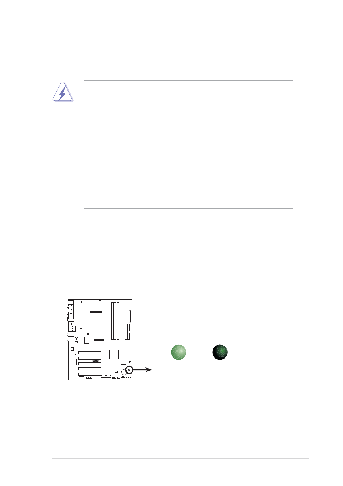
Onboard LED
The motherboard comes with a standby power LED. When lit, this green
LED indicates that the system is ON, in sleep mode, or in soft-off mode, a
reminder that you should shut down the system and unplug the power
cable before removing or plugging in any motherboard component. The
illustration below shows the location of the onboard LED.
SB_PWR
®
K8N-E
K8N-E Onboard LED
ON
Standby
Power
OFF
Powered
Off
ASUS K8N-E Deluxe motherboard
2-1
2.2 Motherboard overview
Before you install the motherboard, study the configuration of your chassis
to ensure that the motherboard fits into it.
Unplug the power cord before installing or removing the motherboard.
Failure to do so may cause you physical injury and damage
motherboard components.
2.2.1 Placement direction
When installing the motherboard, make sure that you place it into the
chassis in the correct orientation. The edge with external ports goes to the
rear part of the chassis as indicated in the image below.
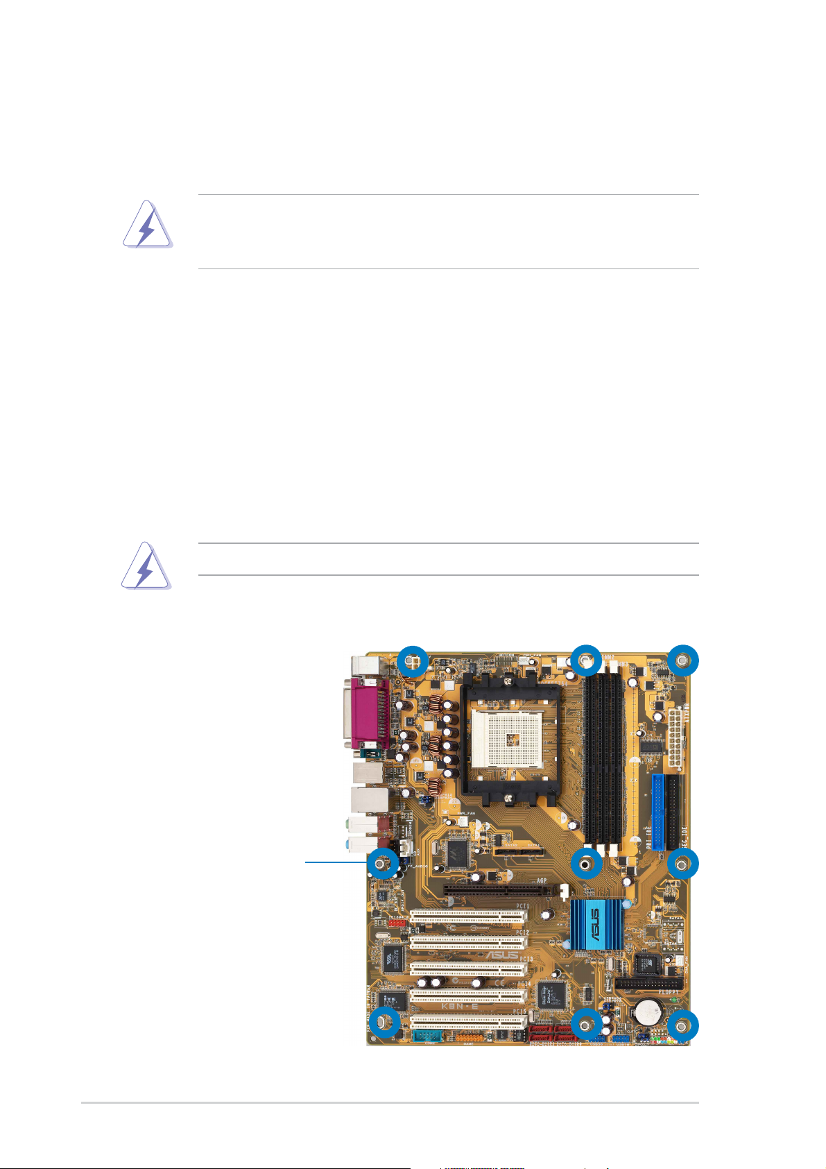
2.2.2 Screw holes
Place nine (9) screws into the holes indicated by circles to secure the
motherboard to the chassis.
Do not overtighten the screws! Doing so can damage the motherboard.
Place this side towards
the rear of the chassis
2-2
Chapter 2: Hardware information
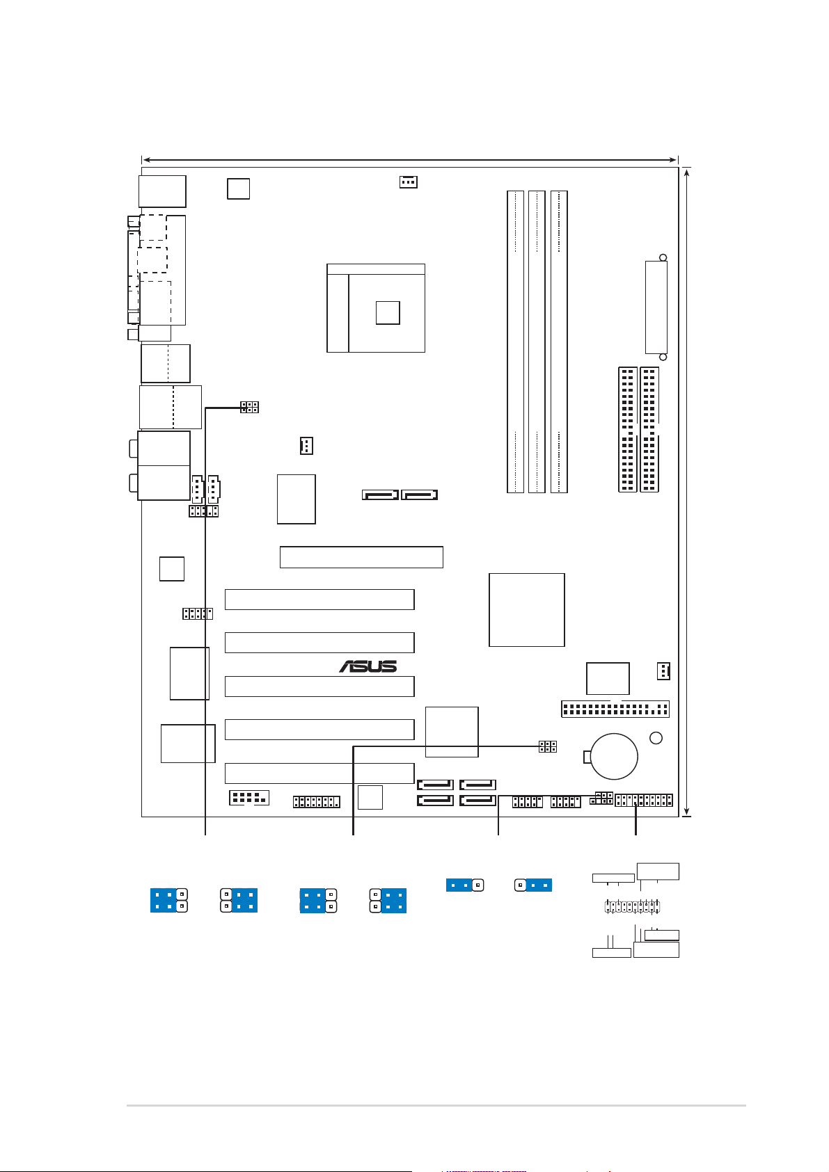
2.2.3 Motherboard layout
24.5cm (9.6in)
PS/2KBMS
T: Mouse
B: Keyboard
SPDIF_O1
SPDIF_O2
ATX12V
PARALLEL PORT
CPU_FAN
COM1
Bottom:
Top:
USB1
1394
USB2
USB2.0
Top:
T: USB3
RJ-45
B: USB4
Top:
Rear Surround L/R
Middle:
Side surround L/R
Bottom:
Center/Subwoofer
Top:Line In
Center:Line Out
Below:Mic In
Audio
Codec
Super
FP_AUDIO
IE1394_2
VIA
VT6307
I/O
USBPW12
USBPW34
CD
Chipset
COM2
AUX
Socket 754
PWR_FAN
SATA2
LAN
PHY
Gigabit
Accelerated Graphics Port (AGP)
PCI1
PCI2
PCI3
PCI4
K8N-E
PCI5
GAME
Speech
Controller
®
SATA1
SATA_RAID1
SATA_RAID2
Silicon Image
SATA
Controller
SATA_RAID3
SATA_RAID4
DDR DIMM2 (64 bit,184-pin module)
DDR DIMM1 (64 bit,184-pin module)
DDR DIMM3 (64 bit,184-pin module)
PRI_IDE
nVIDIA
nForce3
250Gb
4Mbit
BIOS
CHA_FAN
FLOPPY
SB_PWR
PANEL
USB56
USBPW56
USBPW78
USB78
CR2032 3V
Lithium Cell
CMOS Power
CLRTC
CHASSIS
ATX Power Connector
SEC_IDE
30.5cm (12.0in)
USBPW12
USBPW34
21
+5V
(Default)
2
+5VSB
3
USBPW56
USBPW78
21
+5V
(Default)
2
+5VSB
3
ASUS K8N-E Deluxe motherboard
CLRTC
21 3
Normal Clear CMOS
(Default)
2
PANEL
Speaker
PLED+
IDE_LED+
IDE_LED-
PLED-
Connector
Ground
Ground
+5V
PWR
Reset
Ground
Reset SW
ATX Power
Switch*
Speaker
Ground
Power LED
IDE_LED
* Requires an ATX power supply.
2-3
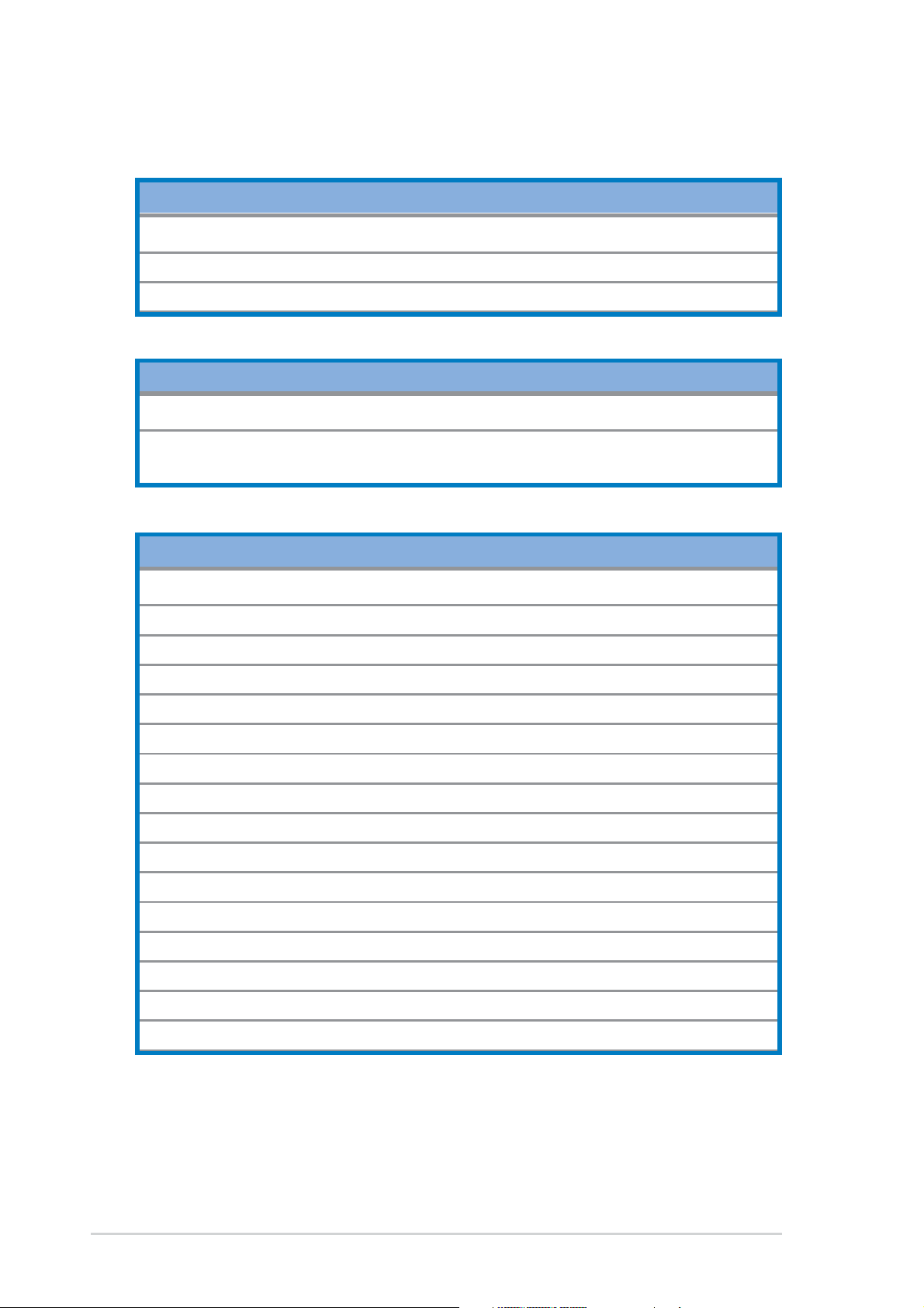
2.2.4 Layout Contents
Slots Page
1. DDR DIMM slots 2-11
2. PCI slots 2-16
3. AGP slot 2-16
Jumpers Page
1. Clear RTC RAM (3-pin CLRTC) 2-17
2. USB device wake-up (3-pin USBPW12, USBPW34,
USBPW56, USBPW78) 2-18
Rear Panel Connectors Page
1. PS/2 mouse port 2-19
2. Parallel port 2-19
3. IEEE 1394 port 2-19
4. Gigabit LAN port (RJ-45) 2-19
5. Rear Speaker out port 2-19
6. Side Speaker out port 2-19
7. Line In jack 2-19
8. Line Out jack 2-19
9. Microphone jack 2-19
10. Center/Subwoofer port 2-20
11. USB 2.0 ports 3 and 4 2-20
12. USB 2.0 ports 1 and 2 2-20
13. Serial connector 2-20
14. S/PDIF optical cable jack 2-20
15. S/PDIF coaxial cable jack 2-20
16. PS/2 keyboard port 2-20
2-4
Chapter 2: Hardware information
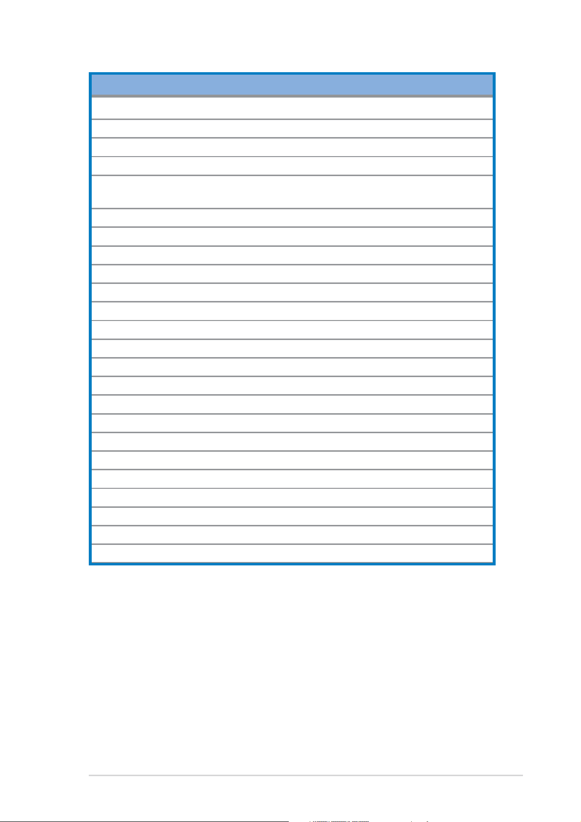
Internal Connectors Page
1. Floppy disk connector (34-1 pin FLOPPY) 2-20
2. Primary IDE connector (40-1 pin PRI_IDE) 2-21
3. Secondary IDE connector (40-1 pin SEC_IDE) 2-21
4. Serial ATA connectors (7-pin SATA1, SATA2) 2-22
5. RAID Serial ATA connectors (7-pin SATA_RAID1,
SATA_RAID2, SATA_RAID3, SATA_RAID4) 2-23
6. CPU fan connector (3-pin CPU_FAN) 2-24
7. Power fan connector (3-pin PWR_FAN) 2-24
8. Chassis fan connector (3-pin CHA_FAN) 2-24
9. Serial Port 2 connector (10-1 pin COM2) 2-24
10. ATX power connector (20-pin ATXPWR) 2-25
11.ATA 12V power connector (4-pin ATX12V) 2-25
12. USB headers (10-1 pin USB56, USB78) 2-26
13. CD connector (4-pin CD) 2-27
14. AUX connector (4-pin AUX) 2-27
15. IEEE 1394 connector (10-1 pin IE1394_1) 2-27
16. Front panel audio connector (10-1 pin FP_AUDIO) 2-28
17. GAME/MIDI connector (16-1 pin GAME) 2-28
18. Chassis intrusion connector (4-1 pin CHASSIS) 2-29
19. System panel connector (20-pin PANEL) 2-29
- System power LED (Green 3-pin PLED)
- System warning speaker (Orange 4-pin SPEAKER)
- Reset switch (Blue 2-pin RESET)
- ATX Power switch (Yellow 2-pin PWRSW)
- Hard disk activity LED (Red 2-pin IDE_LED)
ASUS K8N-E Deluxe motherboard
2-5
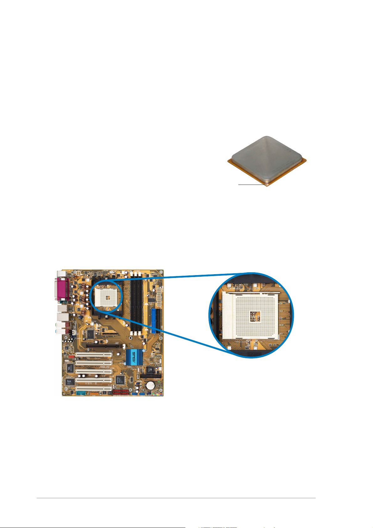
2.3 Central Processing Unit (CPU)
2.3.1 Overview
The motherboard comes with a surface mount 754-pin Zero Insertion
Force (ZIF) socket designed for the AMD Athlon™ 64 processor.
The 128-bit-wide data paths of these processors can run applications
faster than processors with only 32-bit or 64-bit wide data paths.
Take note of the marked corner (with
gold triangle) on the CPU. This mark
should match a specific corner on the
socket to ensure correct installation.
Gold triangle
2.3.2 Installing the CPU
Follow these steps to install a CPU.
1. Locate the 754-pin ZIF socket on the motherboard.
2-6
Chapter 2: Hardware information
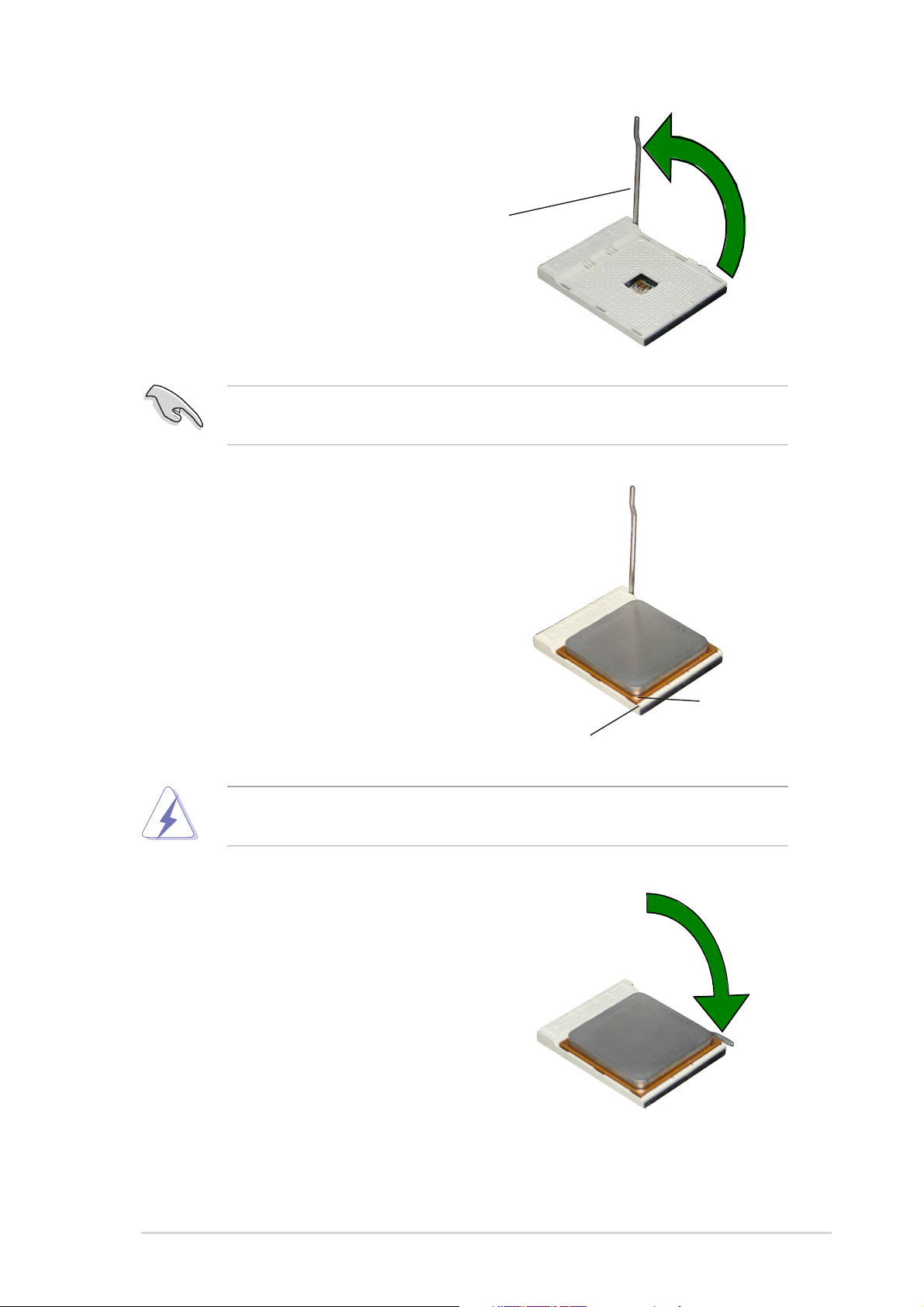
2. Unlock the socket by pressing the
lever sideways, then lift it up to a
90°-100° angle.
Socket Lever
Make sure that the socket lever is lifted up to 90°-100° angle,
otherwise the CPU does not fit in completely.
3. Position the CPU above the
socket such that the CPU corner
with the gold triangle matches the
socket corner with a small
triangle.
4. Carefully insert the CPU into the
socket until it fits in place.
The CPU fits only in one correct orientation. DO NOT force the CPU
into the socket to prevent bending the pins and damaging the CPU!
5. When the CPU is in place, push
down the socket lever to secure
the CPU. The lever clicks on the
side tab to indicate that it is
locked.
Gold triangle
Small triangle
ASUS K8N-E Deluxe motherboard
2-7
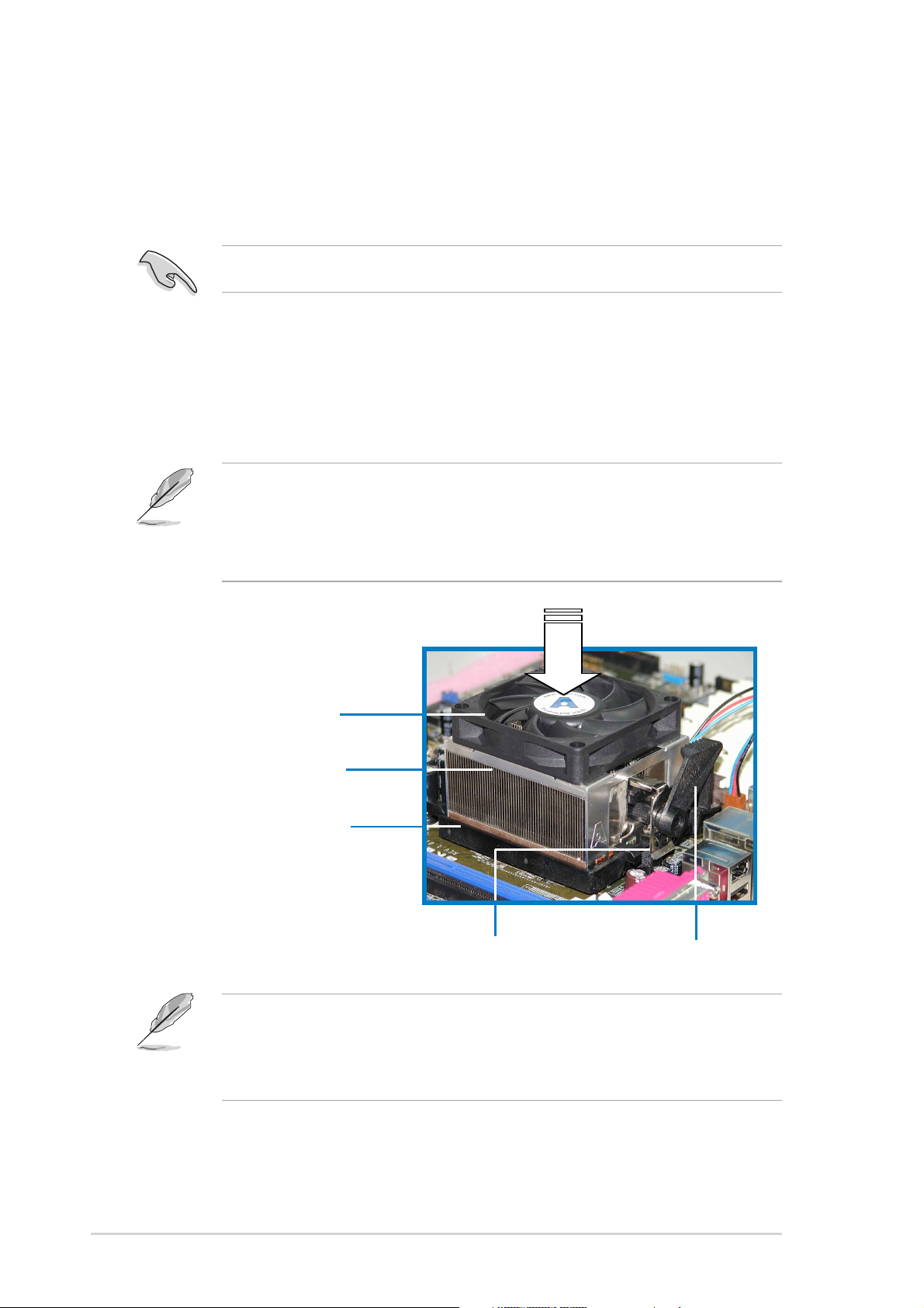
2.3.3 Installing the heatsink and fan
The AMD Athlon™ 64 processor requires a specially designed heatsink
and fan assembly to ensure optimum thermal condition and performance.
Make sure that you use only qualified heatsink and fan assembly.
Follow these steps to install the CPU heatsink and fan.
1. Place the heatsink on top of the installed CPU, making sure that the
heatsink fits properly on the retention module base.
• The retention module base is already installed on the motherboard
upon purchase.
•You do not have to remove the retention module base when
installing the CPU or installing other motherboard components.
CPU Fan
CPU Heatsink
Retention Module Base
Your boxed CPU heatsink and fan assembly should come with
installation instructions for the CPU, heatsink, and the retention
mechanism. If the instructions in this section do not match the CPU
documentation, follow the latter.
Retention bracket lockRetention bracket
2-8
Chapter 2: Hardware information
 Loading...