

Page 1
ESC500 G3
Workstation
User Manual
Page 2

E8318
First Edition
May 2013
Copyright © 2013 ASUSTeK COMPUTER INC. All Rights Reserved.
No part of this manual, including the products and software described in it, may be reproduced,
transmitted, transcribed, stored in a retrieval system, or translated into any language in any form or by any
means, except documentation kept by the purchaser for backup purposes, without the express written
permission of ASUSTeK COMPUTER INC. (“ASUS”).
ASUS provides this manual “as is” without warranty of any kind, either express or implied, including but not
limited to the implied warranties or conditions of merchantability or tness for a particular purpose. In no
event shall ASUS, its directors, ofcers, employees, or agents be liable for any indirect, special, incidental,
or consequential damages (including damages for loss of prots, loss of business, loss of use or data,
interruption of business and the like), even if ASUS has been advised of the possibility of such damages
arising from any defect or error in this manual or product.
Specications and information contained in this manual ae furnished for informational use only, and are
subject to change at any time without notice, and should not be construed as a commitment by ASUS.
ASUS assumes no responsibility or liability for any errors or inaccuracies that may appear in this manual,
including the products and software described in it.
Product warranty or service will not be extended if: (1) the product is repaired, modied or altered, unless
such repair, modication of alteration is authorized in writing by ASUS; or (2) the serial number of the
product is defaced or missing.
Products and corporate names appearing in this manual may or may not be registered trademarks or
copyrights of their respective companies, and are used only for identication or explanation and to the
owners’ benet, without intent to infringe.
ii
Page 3

Contents
Contents ...................................................................................................................... iii
Notices ......................................................................................................................
Safety information ...................................................................................................... ix
About this guide .......................................................................................................... x
Chapter 1: Product introduction
1.1 System package contents ......................................................................... 1-2
1.2 Serial number label ....................................................................................
1.3 Systemspecications ...............................................................................
1.4 Front panel features
1.5 Rear panel features ....................................................................................
1.6 Internal features .........................................................................................
1.7 LED information .........................................................................................
1.7.1 Front panel LED ..........................................................................
1.7.2 LAN (RJ-45) LEDs ......................................................................
................................................................................... 1-5
Chapter 2: Hardware setup
2.1 Chassis cover ............................................................................................. 2-2
2.2 Motherboard overview ...............................................................................
2.3 Central Processing Unit (CPU) .................................................................
2.3.1 CPU installation
2.3.2 Installing the CPU heatsink and fan assembly ............................
2.4 System memory .......................................................................................
2.4.1 Overview ...................................................................................
2.4.2 Memory congurations ..............................................................
2.4.3 Installing a DIMM ......................................................................
2.4.4. To remove a DIMM ....................................................................
2.5 Installing hard disk drives .......................................................................
2.6 Installing 5.25-inch drives .......................................................................
2.6.1 Removing the front panel cover ................................................
2.6.2 Installing 5.25-inch drives into the drive bay .............................
2.6 Installing a Solid-State Drive (SSD) ........................................................
2.7 Expansion slots
2.7.1 Installing expansion cards .........................................................
2.7.2 Conguring an expansion card .................................................
2.8 Removing the system fan
2.9 Connecting cables ...................................................................................
........................................................................................ 2-21
........................................................................... 2-6
........................................................................ 2-26
1-2
1-3
1-6
1-7
1-8
1-8
1-8
2-4
2-5
2-8
2-10
2-10
2-11
2-12
2-12
2-13
2-16
2-16
2-18
2-19
2-22
2-24
2-28
vii
iii
Page 4

Contents
Chapter 3: Motherboard info
3.1 Motherboard layouts..................................................................................3-2
3.2 Onboard buttons and switches ................................................................
3.3 Onboard LEDs ............................................................................................
3.4 Jumpers ....................................................................................................
3.5 Internal connectors ..................................................................................
3.5.1 BIOS update utility ....................................................................
3.5.2 Rear panel connections ............................................................
3.5.3 Audio I/O connections ...............................................................
Chapter 4: BIOS information
4.1 Knowing BIOS ............................................................................................4-2
4.2 BIOS setup program ..................................................................................
4.2.1 EZ Mode
4.2.2 Advanced Mode ..........................................................................
4.3 My Favorites ...............................................................................................
4.4 Main menu ..................................................................................................
4.5 Ai Tweaker menu ......................................................................................
4.6 Advanced menu .......................................................................................
4.6.1 CPU Conguration ....................................................................
4.6.2 PCH Conguration ....................................................................
4.6.3 SATA Conguration ...................................................................
4.6.4 System Agent Conguration
4.6.5 USB Conguration ....................................................................
4.6.6 Platform Misc Conguration ......................................................
4.6.7 Onboard Devices Conguration ................................................
4.6.8 APM ..........................................................................................
4.6.9 Network Stack ...........................................................................
4.7 Monitor menu ...........................................................................................
4.8 Boot menu ................................................................................................
4.9 Tools menu ...............................................................................................
4.9.1 ASUS EZ Flash 2 Utility ............................................................
4.9.2 ASUS O.C. Prole .....................................................................
4.9.3 ASUS SPD Information .............................................................
4.10 Exit menu ..................................................................................................
...................................................................................... 4-4
...................................................... 4-32
3-4
3-7
3-12
3-14
3-25
3-26
3-28
4-3
4-5
4-7
4-8
4-10
4-25
4-26
4-29
4-30
4-34
4-35
4-36
4-38
4-39
4-40
4-43
4-49
4-49
4-49
4-50
4-51
iv
Page 5

Contents
4.11 Updating BIOS .......................................................................................... 4-52
4.11.1 EZ Update .................................................................................
4.11.2 ASUS EZ Flash 2 ......................................................................
4.11.3 ASUS CrashFree BIOS 3 ..........................................................
4.11.4 ASUS BIOS Updater .................................................................
Chapter5: RAIDconguration
5.1 Setting up RAID .......................................................................................... 5-2
5.1.1 RAID denitions ..........................................................................
5.1.2 Installing hard disk drives ............................................................
5.1.3 Setting the RAID mode in BIOS ..................................................
5.1.4 RAID conguration utilities ..........................................................
5.2 Intel
5.3 Intel
®
Rapid Storage Technology Enterprise Option ROM Utility .......... 5-4
5.2.1 Creating a RAID set ....................................................................
5.2.2 Deleting a RAID set
..................................................................... 5-7
5.2.3 Resetting disks to Non-RAID ......................................................
5.2.4 Exiting the
Intel® Rapid Storage Technology enterprise SATA Option
ROM utility....................................................................................................5-9
5.2.5 Rebuilding the RAID
.................................................................... 5-9
5.2.6 Setting the Boot array in the BIOS Setup Utility ........................
®
Rapid Storage Technology enterprise ........................................ 5-12
5.3.1 Creating a RAID set ..................................................................
5.3.2 Changing a Volume Type ..........................................................
5.3.3 Deleting a volume .....................................................................
5.3.4 Preferences ...............................................................................
4-52
4-53
4-54
4-55
5-2
5-3
5-3
5-3
5-5
5-8
5-11
5-13
5-15
5-16
5-17
Chapter 6: Driver installation
6.1 RAID driver installation .............................................................................6-2
6.1.1 Installing the RAID controller driver
6.2 Support DVD information ..........................................................................
6.2.1 Running the support DVD ...........................................................
6.2.2 Obtaining the software manuals
............................................. 6-2
6-4
6-4
.................................................. 6-5
v
Page 6

6.3 Software information .................................................................................6-6
6.3.1 AI Suite 3
6.3.2 DIGI+ VRM ..................................................................................
6.3.3 EPU ...........................................................................................
6.3.4 Fan Xpert 2 ...............................................................................
6.3.5 USB 3.0 Boost
6.3.6 EZ Update .................................................................................
6.3.7 Network iControl
6.3.8 System Information ...................................................................
6.3.9 USB BIOS Flashback ................................................................
6.3.10 USB Charger+ ...........................................................................
6.3.11 Audio congurations
..................................................................................... 6-6
6-8
6-10
6-11
........................................................................... 6-13
6-14
........................................................................ 6-15
6-17
6-19
6-20
.................................................................. 6-21
Appendix: Reference information
Simplexes ............................................................................................................. A-2
ASUS contact information ...................................................................................... A-3
vi
Page 7

Notices
Federal Communications Commission Statement
This device complies with Part 15 of the FCC Rules. Operation is subject to the following two
conditions:
This device may not cause harmful interference, and
•
This device must accept any interference received including interference that may
•
cause undesired operation.
This equipment has been tested and found to comply with the limits for a Class A digital
device, pursuant to Part 15 of the FCC Rules. These limits are designed to provide
reasonable protection against harmful interference in a residential installation. This
equipment generates, uses and can radiate radio frequency energy and, if not installed
and used in accordance with manufacturer’s instructions, may cause harmful interference
to radio communications. However, there is no guarantee that interference will not occur
in a particular installation. If this equipment does cause harmful interference to radio or
television reception, which can be determined by turning the equipment off and on, the user is
encouraged to try to correct the interference by one or more of the following measures:
Reorient or relocate the receiving antenna.
•
Increase the separation between the equipment and receiver.
•
Connect the equipment to an outlet on a circuit different from that to which the
•
receiver is connected.
Consult the dealer or an experienced radio/TV technician for help.
•
WARNING! The use of shielded cables for connection of the monitor to the graphics card
is required to assure compliance with FCC regulations. Changes or modications to this
unit not expressly approved by the party responsible for compliance could void the user’s
authority to operate this equipment.
Canadian Department of Communications Statement
This digital apparatus does not exceed the Class B limits for radio noise emissions from
digital apparatus set out in the Radio Interference Regulations of the Canadian Department
of Communications.
This Class B digital apparatus complies with Canadian ICES-003.
REACH
Complying with the REACH (Registration, Evaluation, Authorization, and Restriction of
Chemicals) regulatory framework, we publish the chemical substances in our products at
ASUS REACH website at http://green.asus.com/english/REACH.htm.
Australia statement notice
From 1 January 2012 updated warranties apply to all ASUS products, consistent with
the Australian Consumer Law. For the latest product warranty details, please visit http://
support.asus.com. Our goods come with guarantees that cannot be excluded under the
Australian Consumer Law. You are entitled to a replacement or refund for a major failure and
compensation for any other reasonably foreseeable loss or damage. You are also entitled
to have the goods repaired or replaced if the goods fail to be of acceptable quality and the
failure does not amount to a major failure.
If you require assistance, please call ASUS Customer Service at 1300 2787 88 or visit us at
http://support.asus.com.
vii
Page 8

ENERGY STAR
ENERGY STAR is a joint program of the U.S. Environmental Protection Agency and the U.S.
Department of Energy helping us all save money and protect the environment through energy
efcient products and practices.
All ASUS products with the ENERGY STAR logo comply with the ENERGY STAR standard,
and the power management feature is enabled by default. The monitor and computer are
automatically set to sleep after 15 and 30 minutes of user inactivity. To wake your computer,
click the mouse or press any key on the keyboard.
Please visit http://www.energy.gov/powermanagement for detail information on power
management and its benets to the environment. In addition, please visit http://www.
energystar.gov for detail information on the ENERGY STAR joint program.
ENERGY STAR is NOT supported on Freedos and Linux-based products.
viii
Page 9

Safety information
Electrical Safety
Before installing or removing signal cables, ensure that the power cables for the system
•
unit and all attached devices are unplugged.
To prevent electrical shock hazard, disconnect the power cable from the electrical outlet
•
before relocating the system.
When adding or removing any additional devices to or from the system, contact a
•
qualied service technician or your dealer. Ensure that the power cables for the devices
are unplugged before the signal cables are connected. If possible, disconnect all power
cables from the existing system before you service.
If the power supply is broken, do not try to x it by yourself. Contact a qualied service
•
technician or your dealer.
Operation Safety
Servicing of this product or unit is to be performed by trained service personnel only.
•
Before operating the server, carefully read all the manuals included with the server
•
package.
Before using the server, make sure all cables are correctly connected and the power
•
cables are not damaged. If any damage is detected, contact your dealer as soon as
possible.
To avoid short circuits, keep paper clips, screws, and staples away from connectors,
•
slots, sockets and circuitry.
Avoid dust, humidity, and temperature extremes. Place the server on a stable surface.
•
This product is equipped with a three-wire power cable and plug for the user’s safety. Use
the power cable with a properly grounded electrical outlet to avoid electrical shock.
CAUTION! Danger of explosion if battery is incorrectly replaced. Replace only with
Lithium-Ion Battery Warning
the same or equivalent type recommended by the manufacturer. Dispose of used
batteries according to the manufacturer’s instructions.
CD-ROM Drive Safety Warning
CLASS 1 LASER PRODUCT
Heavy System
CAUTION! This server system is heavy. Ask for assistance when moving or carrying
the system.
ix
Page 10

DO NOT throw the motherboard in municipal waste. This product has been designed to
enable proper reuse of parts and recycling. This symbol of the crossed out wheeled bin
indicates that the product (electrical and electronic equipment) should not be placed in
municipal waste. Check local regulations for disposal of electronic products.
DO NOT throw the mercury-containing button cell battery in municipal waste. This symbol
of the crossed out wheeled bin indicates that the battery should not be placed in municipal
waste.
About this guide
Audience
This user guide is intended for system integrators and experienced users with at least basic
knowledge of conguring a workstation.
Contents
This guide contains the following parts:
1. Chapter 1: Product Introduction
This chapter describes the general features of the workstation, including sections on
front panel and rear panel specications.
2. Chapter 2: Hardware setup
This chapter lists the hardware setup procedures that you have to perform when
installing or removing system components.
3. Chapter 3: Motherboard information
This chapter gives information about the motherboard that comes with the workstation.
This chapter includes the motherboard layout, jumper settings, and connector
locations.
4. Chapter 4: BIOS information
This chapter tells how to change system settings through the BIOS Setup menus and
describes the BIOS parameters.
5. Chapter5:RAIDconguration
This chapter provides information on how to congure your hard disk drives as RAID
sets.
6. Chapter 6: Driver installation
This chapter provides information on how to install the drivers for system components.
This chapter also describes the software applications that the barebone workstation
supports.
7. Appendix: Reference information
This section provides a troubleshooting guide for solving common problems when
using the barebone workstation.
x
Page 11

Conventions
To make sure that you perform certain tasks properly, take note of the following symbols used
throughout this manual.
DANGER/WARNING: Information to prevent injury to yourself when completing
a task.
CAUTION: Information to prevent damage to the components when completing a
task.
IMPORTANT: Instructions that you MUST follow to complete a task.
NOTE: Tips and additional information to help you complete a task.
Typography
Bold text Indicates a menu or an item to select.
Italics
Used to emphasize a word or a phrase.
<Key> Keys enclosed in the less-than and greater-than sign
means that you must press the enclosed key.
Example: <Enter> means that you must press the
Enter or Return key.
<Key1+Key2+Key3> If you must press two or more keys simultaneously,
the key names are linked with a plus sign (+).
Example: <Ctrl+Alt+D>
Command Means that you must type the command exactly
as shown, then supply the required item or value
enclosed in brackets.
Example: At the DOS prompt, type the command
line: format A:/S
Reference
Visit the ASUS websites worldwide that provide updated information for all ASUS hardware
and software products. Refer to the ASUS contact information for details.
xi
Page 12

xii
Page 13

Chapter 1
This chapter describes the general features
of the workstation, including sections on front
panel and rear panel specications.
Product introduction
1-
Page 14
1.1 System package contents
Check your system package for the following items.
Model Name ESC500 G3
Chassis ASUS T10A Pedestal Chassis
Motherboard ASUS P9D WS
Components 1 x 500W/600W*/700W 80Plus Single Power Supply, Bronze/Gold/Silver
Accessories 1 x ESC500 G3 User Guide
Optional Items Smart card reader
1 x 120x120mm System Fan
1 x Intel LGA1150 CPU Cooler
*600W Power supply is only available for selected countries.
1 x ESC500 G3 Support DVD
1 x Windows® 7/8 Professional Recovery DVD 32-Bit
(for OS bundled SKU)
1 x Windows® 7/8 Professional Recovery DVD 64-Bit
(for OS bundled SKU)
1 x AC Power Cable
1 x COM port cable
1 x DVI-to-VGA converter
If any of the above items is damaged or missing, contact your retailer.
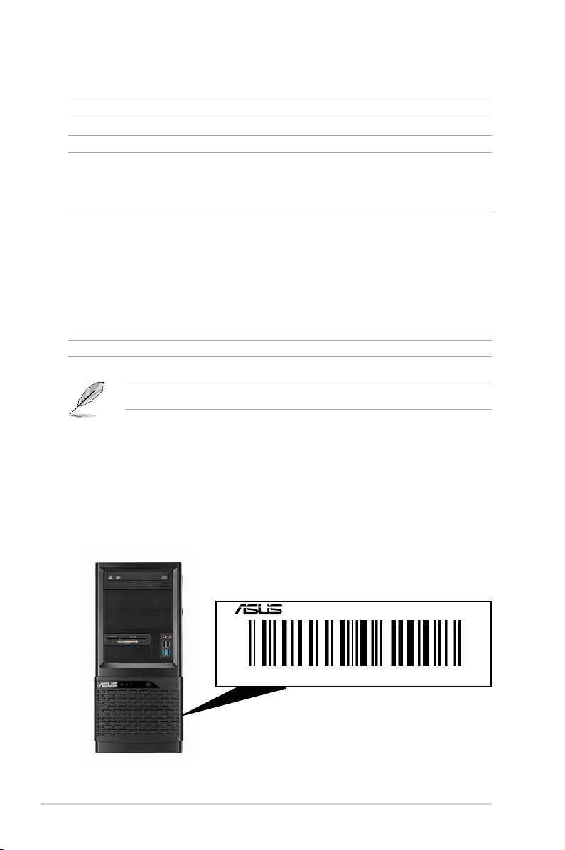
1.2 Serial number label
Before requesting support from the ASUS Technical Support team, take note of the
product’s 12-character serial number as seen in the example xxS0xxxxxxxx below. With
the correct serial number of the product, ASUS Technical Support team members can
quickly identify the server model and provide a satisfactory solution to your technical
issue.
1-2
ESC500 G3
xxS0xxxxxxxx
Chapter 1: Product introduction
Page 15
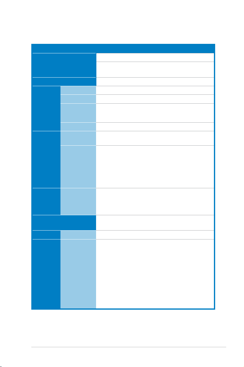
1.3 Systemspecications
The ASUS ESC500 G3 is a workstation featuring the ASUS P9D WS motherboard.
Model Name ESC500 G3
Processor / System Bus
supported
Core Logic Intel® C226 Express Chipset
Total Slots 4 DIMMs (2-Channel per CPU, 4 DIMM per CPU)
Capacity Maximum up to 32GB (UDIMM)
Memory
Memory Type
Memory Size 1GB, 2GB, 4GB, 8GB (UDIMM)
Total PCI/PCIX/PCI-E Slots
Expansion
Slots
Storage
Slot Type
SATA
Controller
HDD Bays
Networking LAN 2 x Intel® I210AT GbE LAN controller
Graphics VGA
1 x Socket LGA1150
Intel® Xeon® E3-1200 v3 Processor Family
Intel® 4th Generation Core™ i3 Processors*
DDR3 1333/1600 ECC/non-ECC UDIMM*
*Refer to www.asus.com for detailed memory AVL & CPU support
list
7
1 x PCIe 3.0 x16 (at x16/x8 mode)
1 x PCIe 3.0 x16 (at x8/x4 mode)
1 x PCIe 3.0 x16 (at x4 mode)
1 x PCIe 2.0 x16 (at x4 mode)
1 x PCIe 2.0 x1 (at x1 mode)
2 x PCI
Intel® C226 chipset:
- 6 x SATA 6Gb/s ports (yellow)
- Intel® Rapid Storage Technology supports RAID 0, 1, 5, and
10 (For Windows OS only)
3 x Internal 3.5” HDD Bays
1 x Internal 2.5” HDD/SSD Bays
Integrated Graphics Processor*
Multi-VGA output support: DVI-I/HDMI/DisplayPort
- Supports DVI with max. resolution 1920x1200 @60Hz
- Supports HDMI with max. resolution 4096x2160 @24Hz
- Supports DisplayPort with max. resolution 3200x2000
@60Hz
Maximum shared memory fo 1GB
Supports Intel® HD Graphics InTru™ 3D, Quick Sync
Video, Clear Video HD Technology, and Insider™
*Integrated graphics is only available for processors that feature
Intel® HD Graphics.
ASUS ESC500 G3
(continued on the next page)
1-3
Page 16
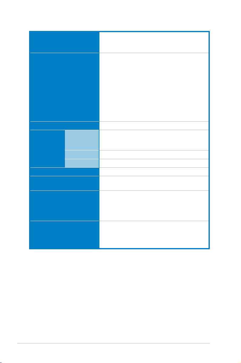
Auxiliary Storage Device Bay
(Floppy / Optical Drive)
3 x 5.25” media bays
Optional DVD-RW optical drive*
*DVD-RW optical drive default for North America.
1 x PS/2 KB/MS port
1 x S/PDIF Out (Optical)
1 x HDMI port
1 x DisplayPort
Onboard I/O
4 x USB 3.0/2.0 ports (2 ports at back panel)
9 x USB 2.0/1.0 ports (4 ports at back panel)
2 x RJ-45 ports
1 x DVI-I port
1 x USB BIOS Flashback switch
1 x 8-channel Audio I/O
Anti-virus Software Optional Anti-Virus CD pack
Europe (CE,
EMI
EN55022 &
EN55024)
V
Taiwan (BSMI) V
China (CCC) V
Dimension (HH x WW x DD) 423mm x 190mm x 435mm
Net Weight Kg (CPU, DRAM &
HDD excluded)
10.8 Kg
500W 80Plus Single Power Supply, Bronze
Power Supply
600W 80Plus Single Power Supply, Gold*
700W 80Plus Single Power Supply, Silver
*600W Power supply is only available for selected countries.
Operating temperature: 10°C~35°C
Environment
Non operating temperature: -40°C~70°C
Non operating humidity: 20%~90% (Non-
condensing)
1-4
Chapter 1: Product introduction
Page 17

1.4 Front panel features
This workstation displays a simple yet stylish front panel with easily accessible features. The
power and reset buttons, LED indicators, optical drive, card reader, and four USB ports are
located on the front panel. For future installation of 5.25-inch devices, two drive bays are
available.
Optical Drive
Empty 5.25-inch bay
Smart Card reader
(optional)
Reset button
HDD access LED (Orange)
Power LED (Blue)
Refer to section 1.7.1 Front panel LED for the LED descriptions.
Microphone / Headphone ports
USB 2.0 ports
USB 3.0 ports
Power button
ASUS ESC500 G3
1-5
Page 18
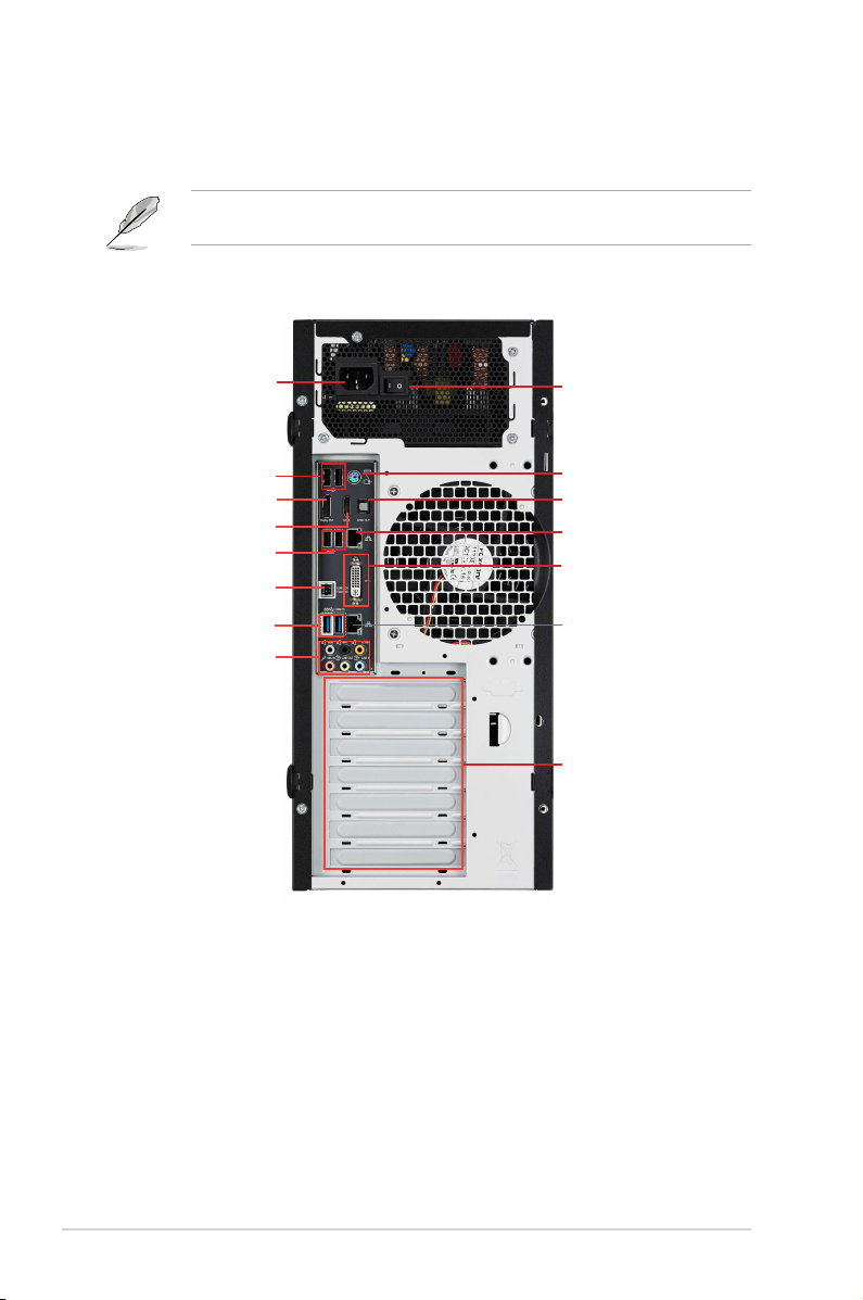
1.5 Rear panel features
The rear panel includes a slot for the motherboard rear I/O ports, expansion slots, and a vent
for the system fan.
The PS/2 keyboard / mouse combo port, USB ports, DVI-I port, Audio ports, S/PDIF Out
port, and Gigabit LAN ports do not appear on the rear panel if motherboard is not installed.
Power cord connector
USB 2.0 ports
DisplayPort
HDMI port
USB 2.0 ports
USB BIOS Flashback button
USB 3.0 ports
Audio I/O ports
Power supply switch
PS/2 keyboard / mouse port
S/PDIF Out
LAN (RJ-45) port 2
DVI port
LAN (RJ-45) port 1
Expansion slots
1-6
Chapter 1: Product introduction
Page 19
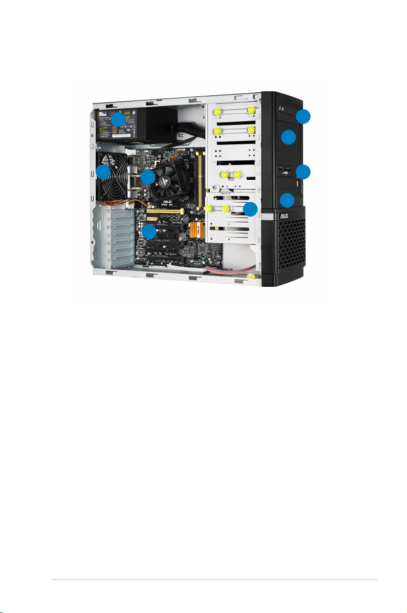
1.6 Internal features
This barebone workstation includes the basic components as shown.
1
2
4
3
1. Power supply unit
2. 120mm system fan
3. ASUS P9D WS motherboard
4. CPU heatsink and fan assembly
5. Optical drive (optional)
6. 5.25-inch drive bays
7. Smart Card reader (optional)
8. Front I/O board
9. Internal HDD bays
5
6
7
8
9
ASUS ESC500 G3
1-7
Page 20
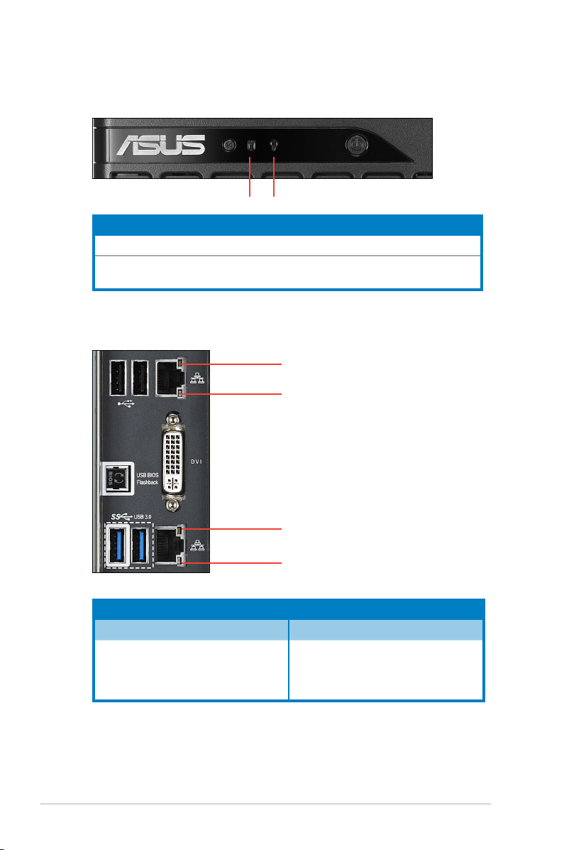
1.7 LED information
1.7.1 Front panel LED
Power LEDHDD Access LED
LED Color Display status Description
Power LED Blue ON System power ON
HDD Access
LED
Orange
1.7.2 LAN (RJ-45) LEDs
OFF
Blinking
No activity
Read/write data into the HDD
ACT/LINK LED
SPEED LED
1-8
ACT/LINK LED
SPEED LED
ACT/LINK LED SPEED LED
Status Description Status Description
OFF No link OFF 10 Mbps connection
YELLOW Linked ORANGE 100 Mbps connection
BLINKING Data activity GREEN 1 Gbps connection
Chapter 1: Product introduction
Page 21

Chapter 2
This chapter lists the hardware setup
procedures that you have to perform
when installing or removing system
components.
Hardware setup
2-
Page 22
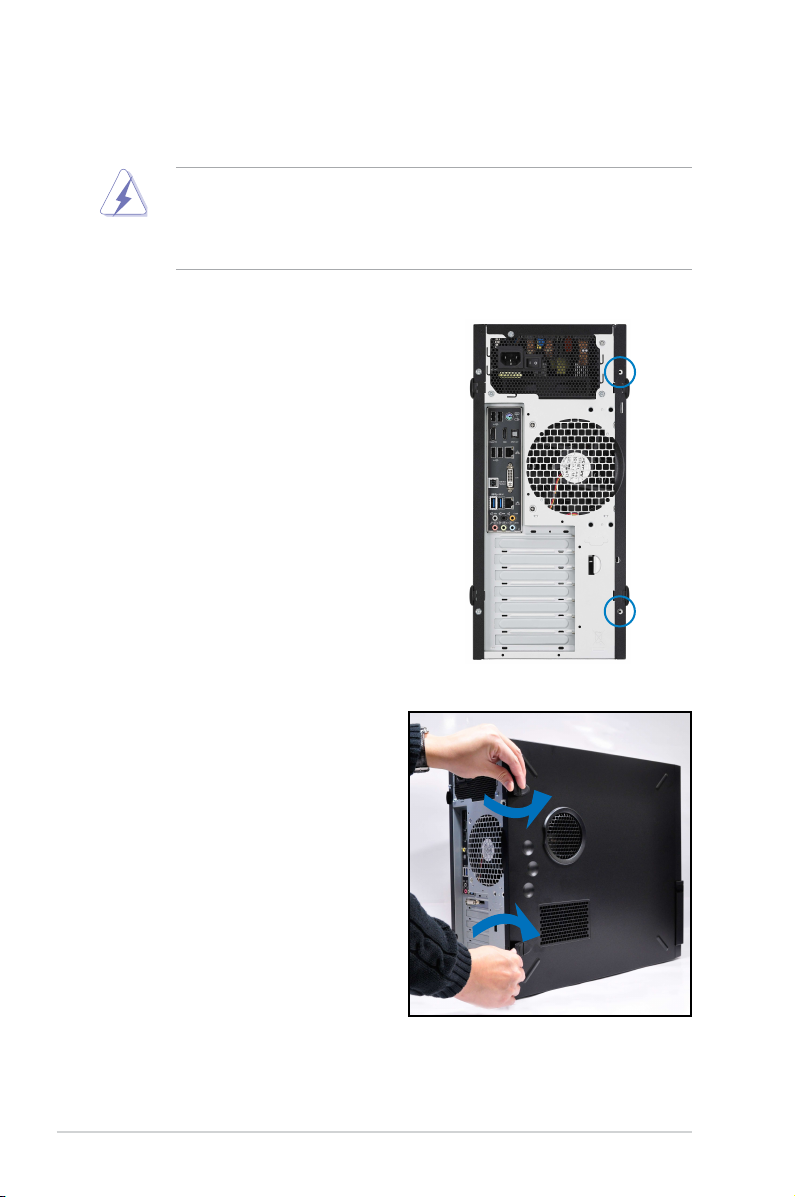
2.1 Chassis cover
Remove the left side cover to install or replace internal components of the server
system.
• Unplug the power cord before removing the side cover.
• Take extra care when removing the side cover. Keep your ngers away
from components inside the chassis that can cause injury, such as the CPU
fan, rear fan, and parts with sharp or protruding edges.
To remove the left side cover:
1. Remove the two screws that secure
the left side cover to the chassis.
2. Unlock the side cover.
Chapter 2: Hardware setup2-2
Page 23
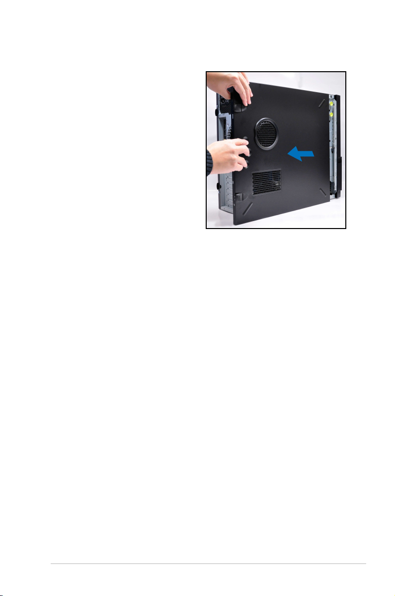
3. Slide the left side cover for about
half an inch toward the rear until
it is disengaged from the chassis.
Carefully lift the cover and set it
aside.
2-3ASUS ESC500 G3
Page 24
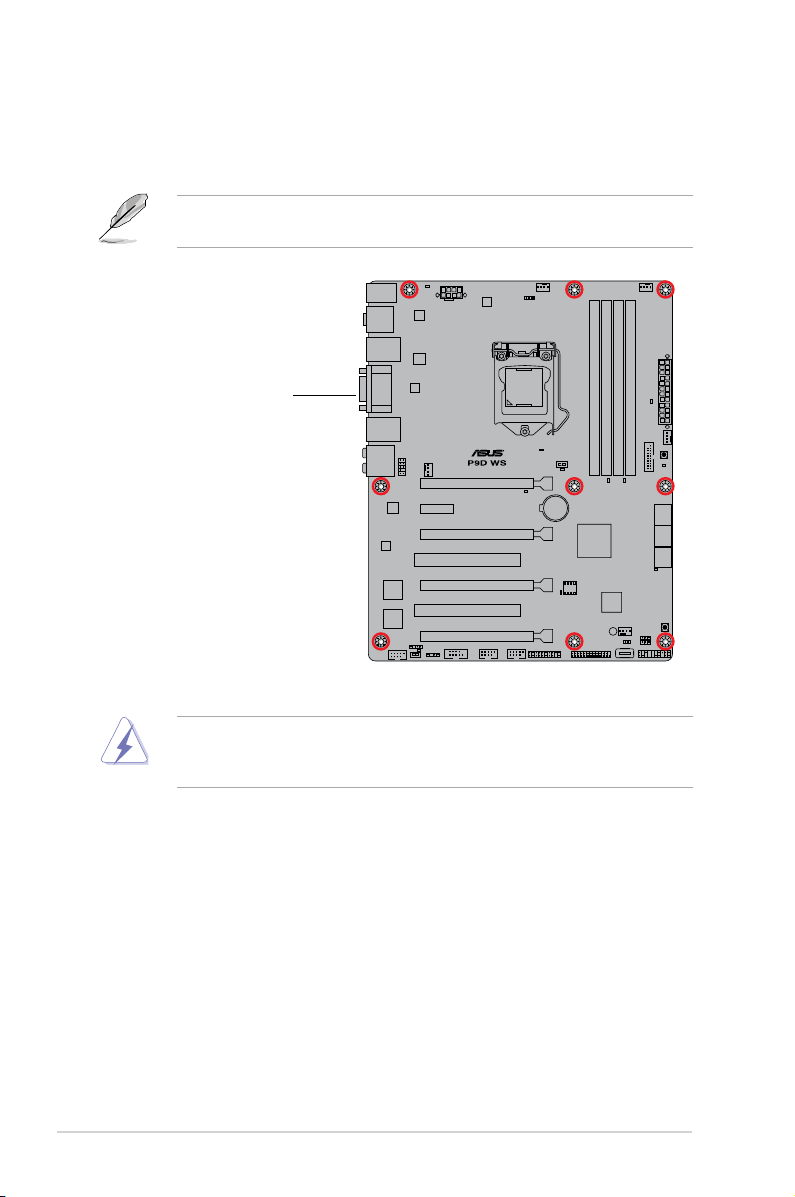
2.2 Motherboard overview
The barebone server comes with the P9D WS motherboard already installed.
The motherboard is secured to the chassis by nine (9) screws as indicated by the
circles in the illustration below.
Refer to Chapter 3: Motherboard information for detailed information on the
motherboard.
Place this side towards
the rear of the chassis
Unplug the power cord before installing or removing any motherboard
component or connection. Failure to do so can cause you physical injury and
damage motherboard components.
Chapter 2: Hardware setup2-4
Page 25
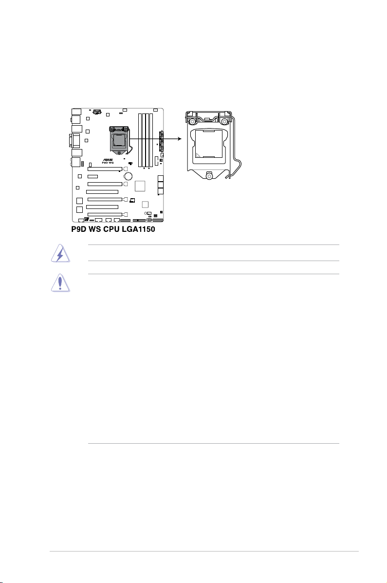
2.3 Central Processing Unit (CPU)
The motherboard comes with a surface mount LGA1150 socket designed for the
Intel® 4th Generation Core™ i3 desktop Processors and Intel® Xeon® E3-1200/
12x5 v3 series Server/Workstation Processors.
Ensure that all power cables are unplugged before installing the CPU.
• Ensure that all power cables are unplugged before installing the CPU.
• Ensure that you install the correct CPU designed for LGA1150 only. DO
NOT install a CPU designed for LGA1155 and LGA1156 sockets on the
LGA1150 socket.
• Upon purchase of the motherboard, ensure that the PnP cap is on
the socket and the socket contacts are not bent. Contact your retailer
immediately if the PnP cap is missing, or if you see any damage to the PnP
cap/socket contacts/motherboard components. ASUS will shoulder the cost
of repair only if the damage is shipment/transit-related.
• Keep the cap after installing the motherboard. ASUS will process Return
Merchandise Authorization (RMA) requests only if the motherboard comes
with the cap on the LGA1150 socket.
• The product warranty does not cover damage to the socket contacts
resulting from incorrect CPU installation/removal, or misplacement/loss/
incorrect removal of the PnP cap.
2-5ASUS ESC500 G3
Page 26

2.3.1 CPU installation
1. Locate the CPU socket on the motherboard.
Before installing the CPU, ensure that the socket box is facing toward you and
the load lever is on your right.
2. Press the load lever with your
thumb (A), then move it to the right
(B) until it is released from the
retention tab.
Do not remove the PnP cap yet
from the CPU socket. Doing so
may bend the pins of the socket.
3. Lift the load lever until the load
plate is completely lifted.
Load lever
Retention tab
4. Position the CPU above the socket,
ensuring that the gold triangle mark
is on the bottom-left corner of the
socket, then t the CPU notches to
the socket's alignment keys.
The CPU ts in only one
orientation. DO NOT force the
CPU into the socket to prevent
bending the pins on the socket
and damaging the CPU.
Load plate
Gold
triangle
mark
Alignment
CPU notches
Alignment
key
key
Chapter 2: Hardware setup2-6
Page 27
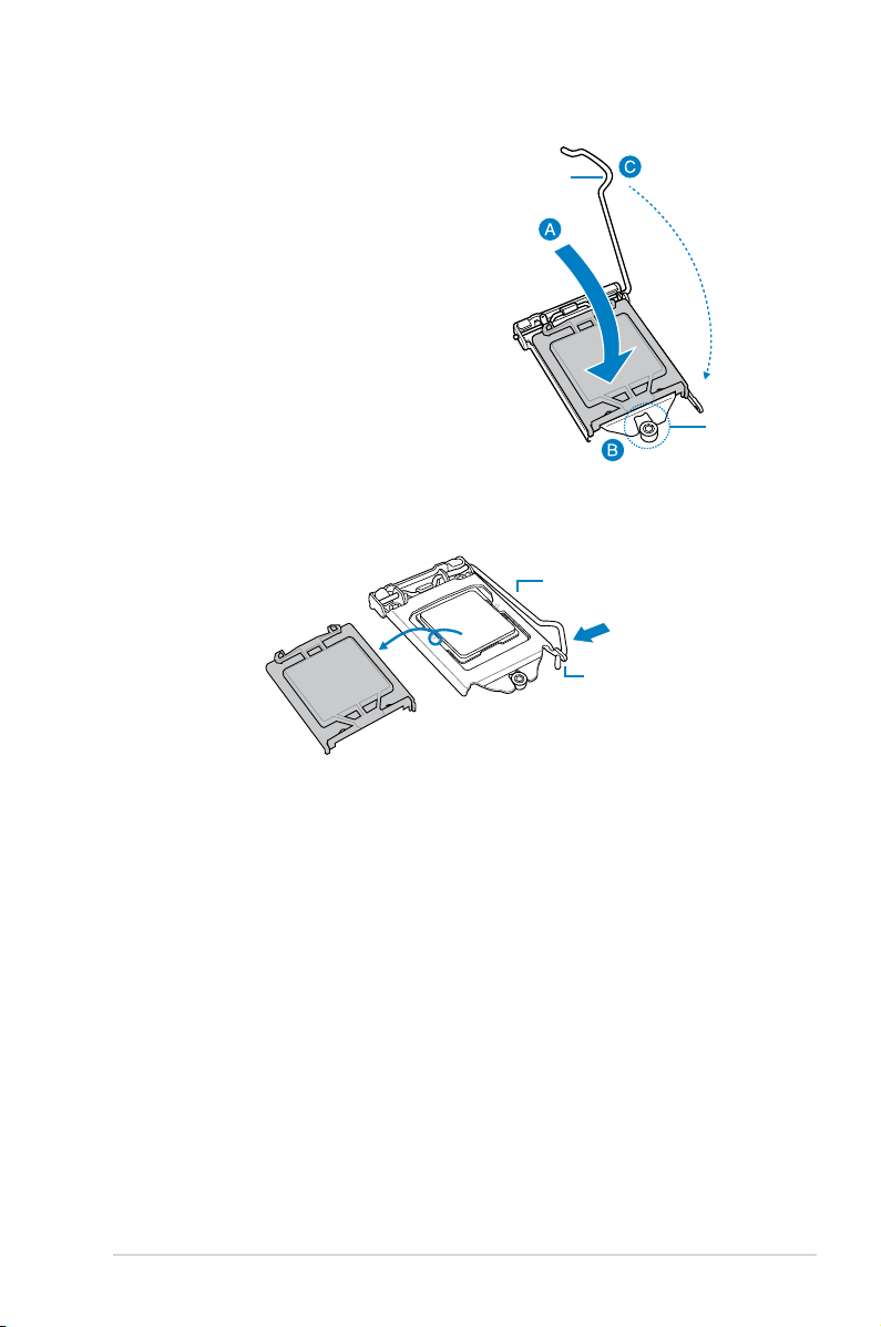
5. Close the load plate (A), ensuring
that the front edge of the load plate
Load lever
slides under the retention lock (B)
then push down the load lever (C).
Retention
lock
6. Insert the load lever under the retention tab to remove the PnP cap from the
CPU socket.
Load lever
Retention tab
2-7ASUS ESC500 G3
Page 28

2.3.2 Installing the CPU heatsink and fan assembly
Apply some Thermal Interface Material to the
exposed area of the CPU that the heatsink will
come in contact with, ensuring that it is evenly
spread in a thin layer.
If the heatsink comes with pre-applied
Thermal Interface Material skip this
step.
The Thermal Interface Material is
toxic and inedible. DO NOT eat it. If
it gets into your eyes or touches your
skin, wash it off immediately and seek
professional medical help.
To install the CPU heatsink and fan assembly
1
B
A
B
A
3 4
2
Chapter 2: Hardware setup2-8
Page 29
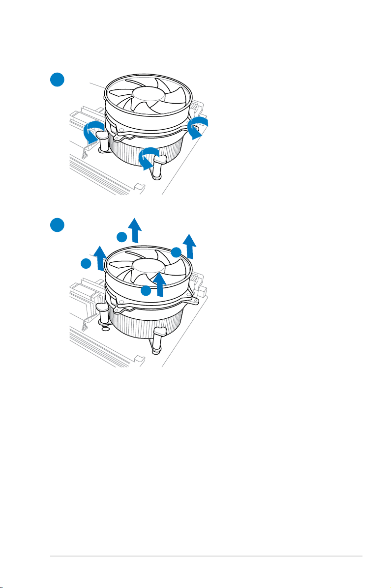
To uninstall the CPU heatsink and fan assembly
1
2
A
B
B
A
2-9ASUS ESC500 G3
Page 30

2.4 System memory
2.4.1 Overview
This motherboard comes with four Double Data Rate 3 (DDR3) Dual Inline Memory
Modules (DIMM) slots.
A DDR3 module is notched differently from a DDR or DDR2 module. DO NOT
install a DDR or DDR2 memory module to the DDR3 slot.
Recommendedmemorycongurations
Chapter 2: Hardware setup2-10
Page 31

2.4.2 Memorycongurations
You may install 1GB, 2GB, 4GB, 8GB unbuffered ECC or non-ECC DDR3 DIMMs
into the DIMM sockets depending on the installed CPU.
• You may install varying memory sizes in Channel A and Channel B. The
system maps the total size of the lower-sized channel for the dual-channel
conguration. Any excess memory from the higher-sized channel is then
mapped for single-channel operation.
• According to Intel CPU spec, DIMM voltage below 1.5V is recommended to
protect the CPU.
• The max. 32GB memory capacity can be supported with DIMMs of 8GB (or
above).
• Always install DIMMs with the same CAS latency. For optimum
compatibility, we recommend that you obtain memory modules from the
same vendor.
• Due to the memory address limitation on 32-bit Windows OS, when you
install 4GB or more memory on the motherboard, the actual usable memory
for the OS can be about 3GB or less. For effective use of memory, we
recommend that you do any of the following:
- Use a maximum of 3GB system memory if you are using a 32-bit
Windows OS.
- Install a 64-bit Windows OS when you want to install 4GB or more on
the motherboard.
For more details, refer to the Microsoft® support site at:
http://support.microsoft.com/kb/929605/en-us.
• This motherboard does not support DIMMs made up of 512Mb (64MB)
chips or less (Memory chip capacity counts in Megabit, 8 Megabit/Mb = 1
Megabyte/MB).
For system stability, use a more efcient memory cooling system to support a
full memory load (4 DIMMs) or overclocking condition.
2-11ASUS ESC500 G3
Page 32

2.4.3 Installing a DIMM
• Unplug the power supply before adding or removing DIMMs or other
system components. Failure to do so may cause severe damage to both
the motherboard and the components.
• Always insert the DIMM into the socket vertically to prevent DIMM notch
damage.
A DIMM is keyed with a notch so that it ts in only one direction. DO NOT force
a DIMM into a socket in the wrong direction to avoid damaging the DIMM.
1
2
3
2.4.4. To remove a DIMM
B
A
Chapter 2: Hardware setup2-12
Page 33

2.5 Installing hard disk drives
This workstation system provides three (3) internal Serial ATA hard disk drive bays.
To install a Serial ATA hard disk drive:
1. Follow the instructions in section
cover.
2. Pull the bay locks outward from the
HDD cage.
3. Lift up the secure tab on the HDD
cage.
2.1 Chassis cover to remove the side
2-13ASUS ESC500 G3
Page 34

4. Swing the HDD cage outwards.
5. With the HDD label side up,
carefully insert the drive into the
3.5-inch bay and push the drive
into the bay until its screw holes
align with the holes on the drive
bay.
6. Push in the bay locks to secure
the hard disk drive in place.
Chapter 2: Hardware setup2-14
Page 35

7. Swing the HDD cage inwards back
to its original position.
8. Push in the bay locks to secure the
hard disk drive in place.
9. Connect a 7-pin SATA cable (from
the motherboard SATA port) and a
15-pin power plug (from the power
supply unit) to the rear connectors
of the hard disk drive.
Use either the 15-pin SATA power connector or the legacy 4-pin power
connector. Do not use both types of power connectors to prevent damage to
components.
2-15ASUS ESC500 G3
Page 36

2.6 Installing 5.25-inch drives
Unplug the power cable before installing or removing any system components.
Failure to do so may cause severe damage to the motherboard and other
system components.
This system comes with three 5.25-inch
drive bays located on the upper front part
of the chassis. If your system came with
an optical drive, the optical drive occupies
the topmost bay (1). The lower bays are
available for additional 5.25-inch optical,
zip, or oppy disk drives (2~3).
You must remove the front panel assembly before installing a 5.25-inch drive.
2.6.1 Removing the front panel cover
To remove the front panel cover:
1
2
3
1. Follow the instructions in section 2.1 Chassis cover to remove the side
cover.
Chapter 2: Hardware setup2-16
Page 37

2. Locate the front panel assembly
lock, then slide it outward to unlock
the front panel.
3. Gently lift the front panel assembly
until the tabs located on the
assembly are detached from the
chassis.
4. Remove the front panel assembly, then set aside.
2-17ASUS ESC500 G3
Page 38

2.6.2 Installing 5.25-inch drives into the drive bay
To install 5.25-inch drives:
1. Select the drive bay you intend to
use and remove the drive slot plate
cover.
2. Release the bay locks by pulling
them outwards.
3. Insert the drive into the 5.25-inch
drive bay and carefully push the
drive into the bay until its screw
holes align with the holes on the
bay.
4. Push in the bay locks to secure the
optical drive
5. Connect a 7-pin SATA cable (from
the motherboard SATA port) and a
15-pin power plug (from the power
supply unit) to the rear connectors
of the hard disk or optical drive.
Chapter 2: Hardware setup2-18
Page 39

6. Reinstall the front panel cover and side covers.
If you are installing an optical drive or hard disk drive, use either the 15-pin
SATA power connector or the legacy 4-pin power connector. Do not use both
types of power connectors to prevent damage to components.
2.6 Installing a Solid-State Drive (SSD)
To install a Solid-State Drive:
1. Locate the four screw holes
underneath the drive cage.
2. Position the SSD so the screw
holes align with the four holes
provided.
2-19ASUS ESC500 G3
Page 40

3. Secure the SSD in place with four
screws.
Swing the drive cage
outwards to access the two
screw holes on the other side
of the drive cage.
4. Connect a 7-pin SATA cable
(from the motherboard SATA
port) and a 15-pin power plug
(from the power supply unit) to
the rear connectors of the SSD.
Use either the 15-pin SATA power connector or the legacy 4-pin power
connector. Do not use both types of power connectors to prevent damage to
components.
Chapter 2: Hardware setup2-20
Page 41

2.7 Expansion slots
Ensure to unplug the power cord before adding or removing expansion cards.
Failure to do so may cause you physical injury and damage motherboard
components.
Slot No. Slot Description
1 PCIe 3.0 x16 (single at Gen3 x16 link or dual at x8/x8 mode)
2 PCIe 2.0 x1 slot (Gen2 x1 link)
3 PCIe 3.0 x16 (single at Gen3 x8 link or dual at x4/x4 mode)
4 PCI slot
5 PCIe 3.0 x16 slot (Gen3 x4 link)
6 PCI slot
7 PCIe 2.0 x16 slot (Gen2 x4 link)
Slot 1 auto switches to x8 link if slot 3 or slot 5 is occupied; Slot 3 auto switches
to x4 link if slot 5 is occupied.
2-21ASUS ESC500 G3
Page 42

2.7.1 Installing expansion cards
Unplug the power cable before installing or removing an expansion card. Failure
to do so may cause severe damage to the motherboard and other system
components!
To install an expansion card:
1. Before installing the expansion card, read the documentation that came with
the card and make the necessary hardware settings.
2. Follow the instructions in section
cover.
3. Lay the system on its side on a at, stable surface.
4. Select the slot that you intend to
use. Remove the screw securing
the metal bracket in place. Remove
the metal bracket and set aside.
2.1 Chassis cover to remove the side
Chapter 2: Hardware setup2-22
Page 43

5. Insert the expansion card into the
PCI slot until the golden connectors
completely t the slot and the
brackets align with the rear panel.
6. Press the card rmly until it is
properly seated on the slot.
7. Secure the card to the chassis with
the bracket screw you removed
earlier.
2-23ASUS ESC500 G3
Page 44

2.7.2 Conguringanexpansioncard
After installing the expansion card, adjust software settings if necessary.
1. Power on the system and change the necessary BIOS settings, if any. See
Chapter 4 for information on BIOS setup.
2. Assign an IRQ to the card. Refer to the tables on the next page.
3. Install the software drivers for the expansion card.
• When using PCI cards on shared slots, ensure that the drivers support
“Share IRQ” or that the cards do not need IRQ assignments. Otherwise,
conicts will arise between the two PCI groups, making the system
unstable and the card inoperable. Refer to the table on the next page for
details.
• By default, if you install a discrete graphics card on the PCIe x16 slot, the
onboard GPU will be automatically disabled. Connect the VGA cable to the
discrete graphics card rst when using a discrete graphics card.
Standard Interrupt assignments
IRQ Priority Standard function
0 1 System Timer
1 2 Keyboard Controller
2 - Programmable Interrupt
4 12 Communications Port (COM1)
5 13 IRQ Holder for PCI Steering
6 14 Reserved
7 15 Reserved
8 3 System CMOS/Real Time Clock
9 4 IRQ Holder for PCI Steering
10 5 IRQ Holder for PCI Steering
11 6 IRQ Holder for PCI Steering
12 7 Reserved
13 8 Numeric Data Processor
14 9 Primary IDE Channel
Chapter 2: Hardware setup2-24
Page 45

IRQ assignments for this motherboard
A B C D E F G H
PCIEx16_1 shared – – – – – – –
PCIEx16_2 shared – – – – – –
PCIEx16_3 – – shared – – – – –
PCIEx16_4 shared – – – – – – –
PCIEx1_1 – shared – – – – – –
PCI1 – shared – – – – – –
PCI2 – – shared – – – – –
VIA1394 – – – shared – – – –
USB3.0 – – – – – shared – –
LAN1 (I210) – – shared – – – – –
LAN2 (I210) – – – – – shared – –
SATA Controller 1 – – – – shared – – –
SATA Controller 2 – – – – shared – – –
USB 2.0 Controller 1 – – – – – – – shared
USB 2.0 Controller 2 – – – – shared – – –
HD Audio – – – – – – shared –
2-25ASUS ESC500 G3
Page 46

2.8 Removing the system fan
You may need to remove previously installed system components when installing
or removing other system components, or when replacing a defective component.
This section tells how to remove the system fan.
To remove the system fan:
1. Disconnect the chassis fan cable from the
motherboard.
CHA_FAN1 connector on the
Chapter 2: Hardware setup2-26
Page 47

2. Locate and remove four system
screws at the rear panel. Keep the
screws for later use.
Hold the system fan with one
hand while removing the system
screws.
3. Remove the system fan, and then
set aside.
2-27ASUS ESC500 G3
Page 48

2.9 Connecting cables
The ESC500 G3 chassis includes the power and signal cables that you need to
connect to the motherboard, storage drives, and other devices that you intend to
install.
• The bundled system cables are connected before shipping. You do not
need to disconnect these cables unless you will remove pre-installed
components to install additional devices.
• Refer to
2
Chapter 3 for detailed information on the connectors.
6
1
5
8
4
7
3
Standard cables connected to the motherboard
1. 24-pin EATX power plug
2. 8-pin EATX 12V power plug
3. Front panel USB 2.0 cable
4. Front panel audio module cable
5. System fan cable
6. CPU fan cable
7. System panel cable
8. Front panel USB 3.0 cable
Chapter 2: Hardware setup2-28
Page 49

Chapter 3
This chapter provides information about the
motherboard that comes with the workstation.
This chapter includes the motherboard layout,
jumper settings, and connector locations.
Motherboard info
3-
Page 50

3.1 Motherboard layouts
P9D WS Motherboard
3-2
Refer to 3.5 Internal Connectors for more information about internal connectors and rear
panel connectors.
Chapter 3: Motherboard information
Page 51

Layout contents
Connectors/Jumpers/Switches/Slots Page
1. Power connectors (24-pin EATXPWR, 8-pin EATX12V) 3-9
2. LGA1150 CPU Socket
3. CPU, chassis, and power fan connectors (4-pin CPU_FAN,
4-pin CHA_FAN1-4)
4. DDR3 DIMM slots
5. MemOK! switch
6. USB 3.0 connector (20-1 pin USB3_12)
7. ASUS Dr. POWER switch
®
8. Intel
C226 Serial ATA 6.0 Gb/s connectors
(7-pin SATA6G_1-6 [yellow])
9. DirectKey button
10. Clear RTC RAM (3-pin CLRTC)
11. System panel connector (20-8 pin PANEL)
12. Chassis Fan control setting (3-pin CHAFAN_SEL)
13. USB 2.0 connectors
(Type A: 10-1 pin USB910/ USB1112; Type B: USB13)
14. Direct connector (2-1 pin DRCT)
15. Parallel port connector (26-1 pin LPT1)
16. Standby Power LED
17. TPM connector (20-1 pin TPM)
18. Serial port connector (10-1 pin COM1)
19. Chassis intrusion connector (4-1 pin CHASSIS)
20. EPU Switch
21. IEEE 1394a port connector (10-1 pin IE1394_1)
22. Digital audio connector (4-1 pin SPDIF_OUT)
23. Front panel audio connector (10-1 pin AAFP)
3-18
3-6
3-16
3-4
3-14
3-5
3-12
3-24
3-13
3-15
3-22
3-16
3-18
3-20
3-19
3-22
3-4
3-17
3-17
3-19
ASUS ESC500 G3
3-3
Page 52

3.2 Onboard buttons and switches
Onboard buttons and switches enhance overclocking and gaming performance when working
on a bare or open-case system.
1. EPU switch
Turning this switch to Enable will automatically detect the current PC loadings and
intelligently moderate power consumption.
To ensure system performance, turn the switch setting to Enable when the system is
powered off.
2. ASUS Dr. POWER switch
This switch allows you to enable or disable the ASUS Dr. Power feature. Install the
bundled ASUS Dr. Power Utility then enable this switch to allow the system to display
notication messages in your Windows screen if a problem is detected with your Power
Supply Unit (PSU).
3-4
Chapter 3: Motherboard information
Page 53

3. DirectKey button
This feature allows your system to go to the BIOS Setup program with the press of
a button. With DirectKey, you can enter the BIOS anytime without having to press
the <Del> key during POST. It also allows you to turn on or turn off your system and
conveniently enter the BIOS during boot-up.
Save your data before using the DirectKey button.
• When the system is on and you press the DirectKey button, your system will shut
down. Press the DirectKey button again or the Power-on button to reboot and enter
the BIOS directly.
• Turn off your system using the power-on button to allow your system to go through
POST (without entering the BIOS) when you reboot your system.
• Refer to section
function.
4.8 Boot Menu for details on setting up the DirectKey default
ASUS ESC500 G3
3-5
Page 54

4. MemOK! button
When you install DIMMs that are not compatible with the motherboard, this may
cause system boot failure, and the DIAG_DRAM near the MemOK switch to light up
continuously. Simply press the MemOK button until the DIAG_DRAM starts blinking to
patch memory compatibility issues and ensure the system’s successful bootup.
• Refer to section 3.3 Onboard LEDs for the exact location of the DIAG_DRAM.
• The DIAG_DRAM also lights when the DIMM is not properly installed. Turn off the
system and reinstall the DIMM before using the MemOK! function.
• The MemOK! button does not function under Windows™ OS environment.
• During the tuning process, the system loads and tests failsafe memory settings. It
takes about 30 seconds for the system to test one set of failsafe settings. If the test
fails, the system reboots and tests the next set of failsafe settings. The blinking speed
of the DIAG_DRAM increases, indicating different test processes.
• Due to memory tuning requirements, the system automatically reboots when each
timing set is tested. If the installed DIMMs still fail to boot after the whole tuning
process, the DIAG_DRAM lights continuously. Replace the DIMMs with ones
recommended in the Memory QVL (Qualied Vendors Lists) in this user manual or on
the ASUS website at www.asus.com.
• If you turn off the computer and replace DIMMs during the tuning process, the system
continues memory tuning after turning on the computer. To stop memory tuning, turn
off the computer and unplug the power cord for about 5–10 seconds.
• If your system fails to boot up due to BIOS overclocking, press the MemOK! button
to boot and load the BIOS default settings. A message will appear during POST
reminding you that the BIOS has been restored to its default settings.
• We recommend that you download and update to the latest BIOS version from the
ASUS website at www.asus.com after using the MemOK! function.
3-6
Chapter 3: Motherboard information
Page 55

3.3 Onboard LEDs
1. POST State LEDs
The POST State LEDs indicate the status of these key components during POST
(Power-on-Self Test): CPU, memory modules, VGA card, and hard disk drive. If an
error is found, the critical component’s LED stays lit until the problem is solved.
2. EPU LED
The EPU LED lights up when the EPU switch is turned to Enable.
ASUS ESC500 G3
3-7
Page 56

3. Standby power LED
This motherboard comes with a standby power LED that lights up to indicate that the
system is ON, in sleep mode, or in soft-off mode. This is a reminder that you should
shut down the system and unplug the power cable before removing or plugging in any
motherboard component. The illustration below shows the location of the onboard LED.
4. DIAG_DRAM
The DIAG_DRAM lights up when the installed DIMMs incompatible with the
motherboard or improperly installed. When using the MemOK! switch for automatic
memory compatibility tuning, the DIAG_DRAM will blink.
3-8
Chapter 3: Motherboard information
Page 57

5. PWR_SUPPLY LED
The ASUS Dr. Power LED near the EATX PWR connector lights up when the ASUS Dr.
Power switch setting is turned to Enable and the power supply unit failed.
6. PGLED3 LED
The ASUS Dr. Power LED near the ASUS Dr. Power switch lights up when the ASUS
Dr. Power switch is turned to enable.
ASUS ESC500 G3
3-9
Page 58

7. +12V_PWR LED
The ASUS Dr. Power LED near the EATX12V connector lights up when the ASUS Dr.
Power switch setting is turned to enable and there is no power detected going into the
processor.
8. CPU warning LED (CPU_PWR_ERR)
The CPU warning LEDs light up to indicate an impending failure of the corresponding
CPU.
3-10
Chapter 3: Motherboard information
Page 59

9. DIMM warning LED (DRAM_PWR_ERR)
The DIMM warning LEDs light up to indicate an impending failure of the corresponding
DIMMs.
ASUS ESC500 G3
3-11
Page 60

3.4 Jumpers
1. Clear RTC RAM (3-pin CLRTC)
This jumper allows you to clear the Real Time Clock (RTC) RAM in CMOS. You can
clear the CMOS memory of date, time, and system setup parameters by erasing
the CMOS RTC RAM data. The onboard button cell battery powers the RAM data in
CMOS, which include system setup information such as system passwords.
To erase the RTC RAM:
1. Turn OFF the computer and unplug the power cord.
2. Move the jumper cap from pins 1-2 (default) to pins 2-3. Keep the cap on pins 2-3
for about 5–10 seconds, then move the cap back to pins 1-2.
3. Plug the power cord and turn ON the computer.
4. Hold down the <Del> key during the boot process and enter BIOS setup to re-
enter data.
3-12
Except when clearing the RTC RAM, never remove the cap on the CLRTC jumper default
position. Removing the cap will cause system boot failure!
• If the steps above do not help, remove the onboard battery and move the jumper
again to clear the CMOS RTC RAM data. After the CMOS clearance, reinstall the
battery.
• You do not need to clear the RTC when the system hangs due to overclocking. For
system failure due to overclocking, use the C.P.R. (CPU Parameter Recall) feature.
Shut down and reboot the system so the BIOS can automatically reset parameter
settings to default values.
• Due to the chipset behavior, AC power off is required to enable C.P.R. function. You
must turn off and on the power supply or unplug and plug the power cord before
rebooting the system.
Chapter 3: Motherboard information
Page 61

2. Chassis Fan control setting (3-pin CHAFAN_SEL)
These jumpers allow you to switch for fan pin selection. The CHAFAN_SEL jumper is
for the front fans and rear fans control. Set to pins 1–2 when using 3-pin fans or pins
2–3 when using 4-pin fans.
• If you use a 4-pin fan but set the jumper to pin 1-2, the fan you installed may not work.
• If you use a 3-pin fan but set the jumper for a 4-pin fan, the fan control will not work
and the fan you installed will always run at full speed.
ASUS ESC500 G3
3-13
Page 62

3.5 Internal connectors
1. Intel® C226 Serial ATA 6.0 Gb/s connectors (7-pin SATA6G_1-6 [yellow])
These connectors connect to Serial ATA 6.0 Gb/s hard disk drives via Serial ATA 6.0
Gb/s signal cables.
3-14
•
These connectors are set to [AHCI Mode] by default. If you intend to create a Serial
ATA RAID set using these connectors, set the SATA Mode item in the BIOS to [RAID
Mode]. Refer to section 4.6.3SATAConguration for details.
• Before creating a RAID set, refer to section Chapter5RAIDcongurations
manual bundled in the motherboard support DVD.
•
When using NCQ, set the SATA Mode in the BIOS to [AHCI Mode]. Refer to section
4.6.3SATAConguration for details.
or the
Chapter 3: Motherboard information
Page 63

2. USB 2.0 connectors
(Type A: 10-1 pin USB910/ USB1112; Type B: USB13)
These connectors are for USB 2.0 ports. Connect the USB module cable to any of
these connectors, then install the module to a slot opening at the back of the system
chassis. These USB connectors comply with USB 2.0 specication that supports up to
480 Mbps connection speed.
Never connect a 1394 cable to the USB connectors. Doing so will damage the
motherboard!
You can connect the front panel USB cable to the ASUS Q-Connector (USB, blue) rst, and
then install the Q-Connector (USB) to the USB connector onboard if your chassis supports
front panel USB ports.
ASUS ESC500 G3
3-15
Page 64

3. USB 3.0 connector (20-1 pin USB3_12)
These connectors allow you to connect a USB 3.0 module for additional USB 3.0 front
or rear panel ports. With an installed USB 3.0 module, you can enjoy all the benets of
USB 3.0 including faster data transfer speeds of up to 5Gbps, faster charging time for
USB-chargeable devices, optimized power efciency and backward compatibility with
USB 2.0.
The USB 3.0 module is purchased separately.
4. Parallel port connector (26-1 pin LPT1)
This connector is for a parallel port. Connect the parallel port module cable to this
connector, then install the module to a slot opening at the back of the system chassis.
3-16
Chapter 3: Motherboard information
Page 65

5. IEEE 1394a port connector (10-1 pin IE1394_1)
This connector is for an IEEE 1394a port. Connect the IEEE 1394a module cable
to this connector, then install the module to a slot opening at the back of the system
chassis.
Never connect a USB cable to the IEEE 1394a connector. Doing so will damage the
motherboard!
The IEEE 1394a module is purchased separately.
6. Digital audio connector (4-1 pin SPDIF_OUT)
This connector is for an additional Sony/Philips Digital Interface (S/PDIF) port. Connect
the S/PDIF Out module cable to this connector, then install the module to a slot
opening at the back of the system chassis.
The S/PDIF module is purchased separately.
ASUS ESC500 G3
3-17
Page 66

7. CPU, chassis, and power fan connectors
(4-pin CPU_FAN, 4-pin CHA_FAN1-4)
Connect the fan cables to the fan connectors on the motherboard, ensuring that the
black wire of each cable matches the ground pin of the connector.
Do not forget to connect the fan cables to the fan connectors. Insufcient air ow inside the
system may damage the motherboard components. These are not jumpers! Do not place
jumper caps on the fan connectors!
3-18
• The CPU_FAN connector supports the CPU fan of maximum 2A (24 W) fan power.
• If you install two VGA cards, we recommend that you plug the rear chassis fan cable
to the motherboard connector labeled CHA_FAN1, CHA_FAN2, CHA_FAN3 for better
thermal environment.
Chapter 3: Motherboard information
Page 67

8. Front panel audio connector (10-1 pin AAFP)
This connector is for a chassis-mounted front panel audio I/O module that supports
either HD Audio or legacy AC`97 audio standard. Connect one end of the front panel
audio I/O module cable to this connector.
• We recommend that you connect a high-denition front panel audio module to this
connector to avail of the motherboard’s high-denition audio capability.
• If you want to connect a high-denition front panel audio module to this connector, set
the Front Panel Type item in the BIOS setup to [HD]; if you want to connect an AC'97
front panel audio module to this connector, set the item to [AC97]. By default, this
connector is set to [HD].
9. Serial port connector (10-1 pin COM1)
This connector is for a serial (COM) port. Connect the serial port module cable to this
connector, then install the module to a slot opening at the back of the system chassis.
The COM module is purchased separately.
ASUS ESC500 G3
3-19
Page 68

10. TPM connector (20-1 pin TPM)
This connector supports a Trusted Platform Module (TPM) system, which can securely
store keys, digital certicates, passwords, and data. A TPM system also helps enhance
network security, protects digital identities, and ensures platform integrity. This
connector can also serve for G.P. Diagnosis card installation.
G.P. Diagnosis card layout
LED 0 and 1
3-20
Power Switch. Press
to turn ON or OFF the
motherboard.
Reset Button. Press to
restart the motherboard.
Card connector
Chapter 3: Motherboard information
Page 69

Installing G.P. Diagnosis card
Ensure to turn off the power supply unit before installing the diagnosis card to avoid
electrical shock hazard.
1. Locate the
TPM connector (20-1 pin TPM) on the motherboard.
2. With the LEDs of the diagnosis card
facing to the PCIe slots, align the card
connector with the TPM connector and
press rmly until the card sits on the
connector completely.
Code table for G.P. Diagnosis card
15, 19 Initiate chip AC OS in PIC mode
E0 Check and wake up system AA OS in APIC mode
2B-2F Prepare system for memory
detection and sizing
32 Early CPU initiation 01 S1
34 Wake up AP 03 S3
98 Detect PS2 mouse/keyboard 04 S4
97 Initiate VGA BIOS 05 S5
9A-9D USB initiation 10 Resume from S1
A2 Detect SATA 30 Resume from S3
B2 Initiate option ROM 40 Resume from S4
A0 Leave BIOS and pass control
to OS
ASUS ESC500 G3
3-21
Page 70

11. Direct Connector (2-pin DRCT)
This connector is for the chassis-mounted button that supports the DirectKey function.
Connect the button cable that supports DirectKey, from the chassis to this connector on
the motherboard.
Ensure that your chassis comes with the extra button cable that supports the DirectKey
feature. Refer to the technical documentation that came with the chassis for details.
12. Chassis intrusion connector (4-1 pin CHASSIS)
This connector is for a chassis-mounted intrusion detection sensor or switch. Connect
one end of the chassis intrusion sensor or switch cable to this connector. The chassis
intrusion sensor or switch sends a high-level signal to this connector when a chassis
component is removed or replaced. The signal is then generated as a chassis intrusion
event.
By default , the pin labeled “Chassis Signal” and “Ground” are shorted with a jumper
cap. Remove the jumper caps only when you intend to use the chassis intrusion
detection feature.
3-22
Chapter 3: Motherboard information
Page 71

13. ATX power connectors (24-pin EATXPWR, 8-pin EATX12V)
These connectors are for ATX power supply plugs. The power supply plugs are
designed to t these connectors in only one orientation. Find the proper orientation and
push down rmly until the connectors completely t.
• For a fully congured system, we recommend that you use a power supply unit
(PSU) that complies with ATX 12 V Specication 2.0 (or later version) and provides a
minimum power of 350 W.
• Do not forget to connect the 8-pin EATX12 V power plug; otherwise, the system will
not boot.
• Use of a PSU with a higher power output is recommended when conguring a system
with more power-consuming devices. The system may become unstable or may not
boot up if the power is inadequate.
• If you are uncertain about the minimum power supply requirement for your system,
refer to the Recommended Power Supply Wattage Calculator at http://support.asus.
com/PowerSupplyCalculator/PSCalculator.aspx?SLanguage=en-us for details.
• If you want to use two or more high-end PCI Express x16 cards, use a PSU with
1000W power or above to ensure the system stability.
ASUS ESC500 G3
3-23
Page 72

14. System panel connector (20-8 pin PANEL)
This connector supports several chassis-mounted functions.
• System power LED (2-pin PWR_LED)
This 2-pin connector is for the system power LED. Connect the chassis power LED
cable to this connector. The system power LED lights up when you turn on the system
power, and blinks when the system is in sleep mode.
• Hard disk drive activity LED (2-pin HDD_LED)
This 2-pin connector is for the HDD Activity LED. Connect the HDD Activity LED cable
to this connector. The HDD LED lights up or ashes when data is read from or written
to the HDD.
• System warning speaker (4-pin SPEAKER)
This 4-pin connector is for the chassis-mounted system warning speaker. The speaker
allows you to hear system beeps and warnings.
• ATX power button/soft-off button (2-pin PWRSW)
This connector is for the system power button. Pressing the power button turns
the system on or puts the system in sleep or soft-off mode depending on the BIOS
settings. Pressing the power switch for more than four seconds while the system is ON
turns the system OFF.
• Reset button (2-pin RESET)
This 2-pin connector is for the chassis-mounted reset button for system reboot without
turning off the system power.
3-24
Chapter 3: Motherboard information
Page 73

3.5.1 BIOS update utility
USB BIOS Flashback
USB BIOS Flashback allows you to easily update the BIOS without entering the existing
BIOS or operating system. Simply insert a USB storage device to the USB port, press the
USB BIOS Flashback button for three seconds, and the BIOS is updated automatically.
To use USB BIOS Flashback:
1. Place the bundled support DVD to the optical drive and install the USB BIOS
Flashback Wizard. Follow the onscreen instructions to complete the installation.
2. Insert the USB storage device to the USB Flashback port.
We recommend you use a USB 2.0 storage device to save the latest BIOS version for
better compatibility and stability.
3. Launch the USB BIOS Flashback Wizard to automatically download the latest BIOS
version.
4. Press the BIOS Flashback button for three seconds until a ashing light appears, which
indicates that the BIOS Flashback function is enabled.
5. Wait until the light goes out, indicating that the BIOS updating process is complete.
For more BIOS update utilities in BIOS setup, refer to the section 4.11 Updating BIOS in
Chapter 4.
• Do not unplug the portable disk, power system, or press the CLR_CMOS button while
BIOS update is ongoing, otherwise update will be interrupted. In case of interruption,
please follow the steps again.
• If the light ashes for ve seconds and turns into a solid light, this means that the
BIOS Flashback is not operating properly. This may be caused by improper installation
of the USB storage device and lename/le format error. If this scenario happens,
please restart the system to turn off the light.
• Updating BIOS may have risks. If the BIOS program is damaged during the process
and results in the system’s failure to boot up, please contact your local ASUS Service
Center.
ASUS ESC500 G3
USB BIOS
Flashback button
USB BIOS
Flashback port
3-25
Page 74

3.5.2 Rear panel connections
Rear panel connectors
1. PS/2 mouse and keyboard port 7. DisplayPort
2. Optical S/PDIF Out port 8. HDMI port
3. LAN (RJ-45) port 2* 9. USB 2.0 ports 5 and 6
4. DVI port 10. USB BIOS Flashback button
5. LAN (RJ-45) port 1* 11. USB 3.0 ports 3 and 4
6. USB 2.0 ports 7 and 8 12. Audio I/O ports**
*and**:RefertothetablesonthenextpageforLANportandaudioportdenitions.
3-26
Chapter 3: Motherboard information
Page 75

• Due to USB 3.0 controller limitation, USB 3.0 devices can only be used under a
Windows® OS environment and after the USB 3.0 driver installation.
• USB 3.0 devices can only be used for data storage.
• We strongly recommend that you connect USB 3.0 devices to USB 3.0 ports for faster
and better performance from your USB 3.0 devices.
* LAN port LED indications
Activity Link LED Speed LED
Status Description Status Description
OFF No link OFF 10 Mbps connection
ORANGE Linked ORANGE 100 Mbps connection
BLINKING Data activity GREEN 1 Gbps connection
ACT/LINK
LED
SPEED
LAN port
LED
**Audio2,4,6,or8-channelconguration
Port Headset
2-channel
Light Blue Line In Line In Line In Line In
Lime Line Out Front Speaker Out Front Speaker Out Front Speaker Out
Pink Mic In Mic In Mic In Mic In
Orange – – Center/Subwoofer Center/Subwoofer
Black – Rear Speaker Out Rear Speaker Out Rear Speaker Out
Gray – – – Side Speaker Out
4-channel 6-channel 8-channel
ASUS ESC500 G3
3-27
Page 76

3.5.3 Audio I/O connections
Audio I/O ports
Connect to Headphone and Mic
Connect to Stereo Speakers
3-28
Chapter 3: Motherboard information
Page 77

Connect to 2.1 channel Speakers
Connect to 4.1 channel Speakers
ASUS ESC500 G3
3-29
Page 78

Connect to 5.1 channel Speakers
Connect to 7.1 channel Speakers
3-30
Chapter 3: Motherboard information
Page 79

Chapter 4
This chapter tells how to change system
settings through the BIOS Setup menus and
describes the BIOS parameters.
BIOS information
Page 80

4.1 Knowing BIOS
The new ASUS UEFI BIOS is a Unied Extensible Interface that complies with UEFI
architecture, offering a user-friendly interface that goes beyond the traditional keyboard-
only BIOS controls to enable a more exible and convenient mouse input. You can easily
navigate the new UEFI BIOS with the same smoothness as your operating system. The
term “BIOS” in this user manual refers to “UEFI BIOS” unless otherwise specied.
BIOS (Basic Input and Output System) stores system hardware settings such as storage
device conguration, overclocking settings, advanced power management, and boot
device conguration that are needed for system startup in the motherboard CMOS. In
normal circumstances, the default BIOS settings apply to most conditions to ensure
optimal performance. DO NOT change the default BIOS settings except in the following
circumstances:
An error message appears on the screen during the system bootup and requests you to
•
run the BIOS Setup.
You have installed a new system component that requires further BIOS settings or
•
update.
Inappropriate BIOS settings may result to instability or boot failure. We strongly
recommend that you change the BIOS settings only with the help of a trained service
personnel.
When downloading or updating the BIOS le, rename it as P9DWS.CAP for this
motherboard.
4-2
Chapter 4: BIOS setup
Page 81

4.2 BIOS setup program
Use the BIOS Setup to update the BIOS or congure its parameters. The BIOS screen
include navigation keys and brief onscreen help to guide you in using the BIOS Setup
program.
Entering BIOS at startup
To enter BIOS Setup at startup:
• Press <Delete> during the Power-On Self Test (POST). If you do not press <Delete>,
POST continues with its routines.
Entering BIOS Setup after POST
To enter BIOS Setup after POST:
• Press <Ctrl>+<Alt>+<Delete> simultaneously.
• Press the reset button on the system chassis.
• Press the power button to turn the system off then back on. Do this option only if you
failed to enter BIOS Setup using the rst two options.
• The BIOS setup screens shown in this section are for reference purposes only, and
may not exactly match what you see on your screen.
• Ensure that a USB mouse is connected to your motherboard if you want to use the
mouse to control the BIOS setup program.
• If the system becomes unstable after changing any BIOS setting, load the default
settings to ensure system compatibility and stability. Select the Load Optimized
Defaults item under the Exit menu or press hotkey <F5>. See section 4.10 Exit Menu
for details.
• If the system fails to boot after changing any BIOS setting, try to clear the CMOS and
reset the motherboard to the default value. See section 3.2 Onboard buttons and
switches for information on how to erase the RTC RAM via the Clear CMOS button.
• The BIOS setup program does not support the bluetooth devices.
BIOS menu screen
The BIOS Setup program can be used under two modes: EZ Mode and Advanced Mode.
You can change modes from the Exit menu or from the Exit/Advanced Mode screen.
ASUS ESC500 G3
4-3
Page 82

4.2.1 EZ Mode
By default, the EZ Mode screen appears when you enter the BIOS setup program. The EZ
Mode provides you an overview of the basic system information, and allows you to select
the display language, system performance mode and boot device priority. To access the
Advanced Mode, click Exit/Advanced Mode, then select Advanced Mode or press <F7> hot
key for the advanced BIOS settings.
The default screen for entering the BIOS setup program can be changed. Refer to the
Setup Mode item in section 4.7 Boot menu for details.
Displays the CPU/motherboard
temperature, CPU/5V/3.3V/12V voltage
output, CPU/chassis/power fan speed
Displays the selected
shortcut items
Selects the boot
device priority
Displays the Advanced
mode menus
Selects the display language
of the BIOS setup program
Selects the boot
device priority
Displays the system properties of the
selected mode on the right hand side
Exits the BIOS setup program
without saving the changes, saves
the changes and resets the system,
or enters the Advanced Mode
Loads optimized
default settings
4-4
• The boot device options vary depending on the devices you installed to the system.
• The
Boot Menu(F8) button is available only when the boot device is installed to the
system.
Chapter 4: BIOS setup
Page 83

4.2.2 Advanced Mode
The Advanced Mode provides advanced options for experienced end-users to congure
the BIOS settings. The gure below shows an example of the Advanced Mode. Refer to the
following sections for the detailed congurations.
To access the Advanced Mode, click Exit, then select Advanced Mode or press F7 hotkey.
Back button
Menu bar
Menu items
Menu bar
The menu bar on top of the screen has the following main items:
Submenu item
Pop-up window
Congurationelds
Scroll bar
Navigation keys
General help
Lastmodied
settings
Quick note
My Favorites For saving the frequently-used system settings and conguration.
Main For changing the basic system conguration
Ai Tweaker For changing the overclocking settings
Advanced For changing the advanced system settings
Monitor
For displaying the system temperature, power status, and changing the
fan settings.
Boot For changing the system boot conguration
Tool For conguring options for special functions
Exit For selecting the exit options and loading default settings
ASUS ESC500 G3
4-5
Page 84

Menu items
The highlighted item on the menu bar displays the specic items for that menu. For example,
selecting Main shows the Main menu items.
The other items (Ai Tweaker, Advanced, Monitor, Boot, Tool, and Exit) on the menu bar have
their respective menu items.
Back button
This button appears when entering a submenu. Press <Esc> or use the USB mouse to click
this button to return to the previous menu screen.
Submenu items
A greater than sign (>) before each item on any menu screen means that the item has a
submenu. To display the submenu, select the item and press <Enter>.
Pop-up window
Select a menu item and press <Enter> to display a pop-up window with the conguration
options for that item.
Scroll bar
A scroll bar appears on the right side of a menu screen when there are items that do not t on
the screen. Press the Up/Down arrow keys or <Page Up> / <Page Down> keys to display the
other items on the screen.
Navigation keys
At the bottom right corner of the menu screen are the navigation keys for the BIOS setup
program. Use the navigation keys to select items in the menu and change the settings.
If you delete all shortcut items from the F3: Shortcut list, the default shortcut items will
reappear after your next startup.
General help
At the top right corner of the menu screen is a brief description of the selected item. Use
<F12> key to capture the BIOS screen and save it to the removable storage device.
Congurationelds
These elds show the values for the menu items. If an item is user-congurable, you can
change the value of the eld opposite the item. You cannot select an item that is not
user-congurable.
A congurable eld is highlighted when selected. To change the value of a eld, select it and
press <Enter> to display a list of options.
Quick Note button
This button allows you to enter notes of the activities that you have done in BIOS.
• The Quick Note function does not support the following keyboard functions: delete,
cut, copy and paste.
• You can only use the alphanumeric characters to enter your notes.
4-6
Chapter 4: BIOS setup
Page 85

LastModiedbutton
This button shows the items that you last modied and saved in BIOS Setup.
4.3 My Favorites
MyFavorites is your personal space where you can easily save and access your favorite
BIOS items.
Adding items to My Favorites
To add frequently-used BIOS items to My Favorites:
1. Use the arrow keys to select an item that you want to add. When using a mouse, hover
the pointer to the item.
2. Press <F4> on your keyboard or right-click on your mouse to add the item to My
Favorites page.
You cannot add the following items to My Favorites:
• Items with submenu options
• User-congurable items such as language and boot device order
• Conguration items such as Memory SPD Information, system time and date
ASUS ESC500 G3
4-7
Page 86

4.4 Main menu
The Main menu screen appears when you enter the Advanced Mode of the BIOS Setup
program. The Main menu provides you an overview of the basic system information, and
allows you to set the system date, time, language, and security settings.
Security
The Security menu items allow you to change the system security settings.
4-8
• If you have forgotten your BIOS password, erase the CMOS Real Time Clock (RTC)
RAM to clear the BIOS password. See section 3.2 Onboard buttons and switches
for information on how to erase the RTC RAM via the Clear CMOS button.
• The Administrator or User Password items on top of the screen show the default
Installed]. After you set a password, these items show [Installed].
[Not
Chapter 4: BIOS setup
Page 87

Administrator Password
If you have set an administrator password, we recommend that you enter the administrator
password for accessing the system. Otherwise, you might be able to see or change only
selected elds in the BIOS setup program.
To set an administrator password:
1. Select the
2. From the
3. Conrm the password when prompted.
To change an administrator password:
1. Select the
2. From the
<Enter>.
3. From the
4. Conrm the password when prompted.
To clear the administrator password, follow the same steps as in changing an administrator
password, but press <Enter> when prompted to create/conrm the password. After you clear
the password, the Administrator Password item on top of the screen shows Not Installed.
Administrator Password item and press <Enter>.
Create New Password box, key in a password, then press <Enter>.
Administrator Password item and press <Enter>.
Enter Current Password box, key in the current password, then press
Create New Password box, key in a new password, then press <Enter>.
User Password
If you have set a user password, you must enter the user password for accessing the system.
The User Password item on top of the screen shows the default Not Installed. After you set a
password, this item shows Installed.
To set a user password:
1. Select the
2. From the
3. Conrm the password when prompted.
ASUS ESC500 G3
User Password item and press <Enter>.
Create New Password box, key in a password, then press <Enter>.
4-9
Page 88

To change a user password:
1. Select the
2. From the
User Password item and press <Enter>.
Enter Current Password box, key in the current password, then press
<Enter>.
3. From the
Create New Password box, key in a new password, then press <Enter>.
4. Conrm the password when prompted.
To clear the user password, follow the same steps as in changing a user password, but press
<Enter> when prompted to create/conrm the password. After you clear the password, the
User Password item on top of the screen shows Not Installed.
4.5 Ai Tweaker menu
The Ai Tweaker menu items allow you to congure overclocking-related items.
Be cautious when changing the settings of the Ai Tweaker menu items. Incorrect eld
values can cause the system to malfunction.
The conguration options for this section vary depending on the CPU and DIMM model you
installed on the motherboard.
Scroll down to display other BIOS items.
4-10
Chapter 4: BIOS setup
Page 89

Ai Overclock Tuner [Auto]
Allows you to select the CPU overclocking options to achieve the desired CPU internal
frequency. Select any of these preset overclocking conguration options:
[Auto] Loads the optimal settings for the system.
[X.M.P.] Allows your system to automatically optimize the CPU ratio, BCLK
frequency, and memory parameters. If you install memory modules
supporting the eXtreme Memory Prole (X.M.P.) Technology, select this
item to set the proles supported by your memory modules for optimizing
the system performance.
The following item appears only when you set the Ai Overclocking Tuner to [X.M.P.].
eXtremeMemoryProle
Allows you to select the X.M.P. mode supported by your memory module.
Conguration options: [Prole #1] [Prole #2]
ASUS MultiCore Enhancement [Enabled]
[Enabled] Default set to [Enabled] for maximum performance under XMP/Manual/
[Disabled] Allows you to set to default core ratio settings.
User-dened memory frequency mode.
CPU Core Ratio [Auto]
Allows you to set the CPU ratio and synchronize automatically either per core or all cores.
Conguration options: [Auto] [Sync All Cores] [Per Core]
When the CPU Core Ratio is set to [Per Core], the following item appears:
1-Core Ratio Limit [Auto]
Select [Auto] to apply the CPU default Turbo Ratio setting or manually
assign a 1-Core Limit value that must be higher than or equal to the 2-Core
Ratio Limit.
2-Core Ratio Limit [Auto]
Select [Auto] to apply the CPU default Turbo Ratio setting or manually
assign a 2-Core Limit value that must be higher than or equal to the 3-Core
Ratio Limit.
If you assign a value for 2-Core Ratio Limit, do not set the 1-Core Ratio Limit to [Auto].
3-Core Ratio Limit [Auto]
Select [Auto] to apply the CPU default Turbo Ratio setting or manually
assign a 3-Core Limit value that must be higher than or equal to the 4-Core
Ratio Limit.
If you assign a value for 3-Core Ratio Limit, do not set the 1-Core Ratio Limit and 2-Core
Ratio Limit to [Auto].
ASUS ESC500 G3
4-11
Page 90

4-Core Ratio Limit [Auto]
Select [Auto] to apply the CPU default Turbo Ratio setting or manually
assign a 4-Core Limit value that must be higher than or equal to the 3-Core
Ratio Limit.
If you assign a value for 4-Core Ratio Limit, do not set the 1-Core Ratio Limit, 2-Core Ratio
Limit, and 3-Core Ratio to [Auto].
Min CPU Cache Ratio [Auto]
Allows you to set the minimum possible ratio on the Uncore part of the processor. Use the
<+> or <-> keys to adjust the value. The values depend on the CPU installed.
Max CPU Cache Ratio [Auto]
Allows you to set the maximum possible ratio on the Uncore part of the processor. Use the
<+> or <-> keys to adjust the value. The values depend on the CPU installed.
Memory Frequency [Auto]
Allows you to set the memory operating frequency. The conguration options vary with the
BCLK/PCIE Frequency item settings.
CPU Graphics Max. Ratio [Auto]
Allows you to optimize the CPU Graphics Ratio depending on the system loading. Use the
<+> or <-> keys to adjust the value.
EPU Power Saving Mode [Disabled]
Allows you to enable or disable the EPU power saving function.
Conguration options: [Disabled] [Enabled]
DRAM Timing Control
The subitems in this menu allow you to set the DRAM timing control features. Use the <+> or
<-> keys to adjust the value. To restore the default setting, type [auto] using the keyboard and
press the <Enter> key.
4-12
Changing the values in this menu may cause the system to become unstable! If this
happens, revert to the default settings.
Chapter 4: BIOS setup
Page 91

Primary Timings
DRAM CAS# Latency [Auto]
Conguration options: [Auto] [1] – [31]
DRAM RAS# to CAS# Delay [Auto]
Conguration options: [Auto] [1] – [31]
DRAM RAS# PRE Time [Auto]
Conguration options: [Auto] [1] – [31]
DRAM RAS# ACT Time [Auto]
Conguration options: [Auto] [1] – [63]
DRAM Command Rate [Auto]
Conguration options: [Auto] [1] – [3]
Secondary Timings
DRAM RAS# to RAS# Delay [Auto]
Conguration options: [Auto] [1] – [15]
DRAM REF Cycle Time [Auto]
Conguration options: [Auto] [1] – [511]
DRAM Refresh Interval [Auto]
Conguration options: [Auto] [1] – [65535]
DRAM WRITE Recovery Time [Auto]
Conguration options: [Auto] [1] – [16]
DRAM READ to PRE Time [Auto]
Conguration options: [Auto] [1] – [15]
DRAM FOUR ACT WIN Time [Auto]
Conguration options: [Auto] [1] – [255]
DRAM WRITE to READ Delay [Auto]
Conguration options: [Auto] [1] – [15]
DRAM CKE Minimum pulse width [Auto]
Conguration options: [Auto] [1] – [15]
DRAM CAS# Write Latency [Auto]
Conguration options: [Auto] [1] – [31]
RTL IOL control
DRAM RTL initial Value [Auto]
Conguration options: [Auto] [1] - [63]
DRAM RTL (CHA_R0D0) [Auto]
Conguration options: [Auto] [1] - [63]
DRAM RTL (CHA_R0D1) [Auto]
Conguration options: [Auto] [1] - [63]
ASUS ESC500 G3
4-13
Page 92

DRAM RTL (CHA_R1D0) [Auto]
Conguration options: [Auto] [1] - [63]
DRAM RTL (CHA_R1D1) [Auto]
Conguration options: [Auto] [1] - [63]
DRAM RTL (CHB_R0D0) [Auto]
Conguration options: [Auto] [1] - [63]
DRAM RTL (CHB_R0D1) [Auto]
Conguration options: [Auto] [1] - [63]
DRAM RTL (CHB_R1D0) [Auto]
Conguration options: [Auto] [1] - [63]
DRAM RTL (CHB_R1D1) [Auto]
Conguration options: [Auto] [1] - [63]
DRAM IO-L (CHA_R0D0) [Auto]
Conguration options: [Auto] [1] - [15]
DRAM IO-L (CHA_R0D1) [Auto]
Conguration options: [Auto] [1] - [15]
DRAM IO-L (CHA_R1D0 [Auto]
Conguration options: [Auto] [1] - [15]
DRAM IO-L (CHA_R1D1 [Auto]
Conguration options: [Auto] [1] - [15]
DRAM IO-L (CHB_R0D0 [Auto]
Conguration options: [Auto] [1] - [15]
DRAM IO-L (CHB_R0D1) [Auto]
Conguration options: [Auto] [1] - [15]
DRAM IO-L (CHB_R1D0 [Auto]
Conguration options: [Auto] [1] - [15]
DRAM IO-L (CHB_R1D1 [Auto]
Conguration options: [Auto] [1] - [15]
Third Timings
tRDRD [Auto]
Conguration options: [Auto] [1] – [7]
tRDRD_dr [Auto]
Conguration options: [Auto] [1] – [15]
tRDRD_dd [Auto]
Conguration options: [Auto] [1] – [15]
tWRRD [Auto]
Conguration options: [Auto] [1] – [63]
4-14
Chapter 4: BIOS setup
Page 93

tWRRD_dr [Auto]
Conguration options: [Auto] [1] – [15]
tWRRD_dd [Auto]
Conguration options: [Auto] [1] – [15]
tWRWR [Auto]
Conguration options: [Auto] [1] – [7]
tWRWR_dr [Auto]
Conguration options: [Auto] [1] – [15]
tWRWR_dd [Auto]
Conguration options: [Auto] [1] – [15]
Dec_WRD [Auto]
Conguration options: [Auto] [0] – [1]
tRDWR [Auto]
Conguration options: [Auto] [1] – [31]
tRDWR_dr [Auto]
Conguration options: [Auto] [1] – [31]
tRDWR_dd [Auto]
Conguration options: [Auto] [1] – [31]
MISC
MRC Fast Boot [Auto]
Allows you to enable, disable or automatically set the MRC fast boot.
Conguration options: [Auto] [Enable] [Disable]
DRAM CLK Period [Auto]
Conguration options: [Auto] [1] – [14]
Channel A DIMM Control [Enable Bot...]
Conguration options: [Enable Both DIMMS] [Disable DIMM0] [Disable DIMM1]
[Disable Both DIMMS]
Channel B DIMM Control [Enable Bot...]
Conguration options: [Enable Both DIMMS] [Disable DIMM0] [Disable DIMM1]
[Disable Both DIMMS]
Scrambler Setting [Optimized ...]
Allows you to set the optimized scrambler setting for stability.
Conguration options: [Optimized (ASUS)] [Default (MRC)]
ASUS ESC500 G3
4-15
Page 94

DIGI+ Power Control
CPU Load-Line Calibration [Auto]
Load-line is dened by Intel® VRM specication and affects CPU power voltage. The
CPU working voltage will decrease proportionally to CPU loading. Higher load-line
calibration could get higher voltage and good overclocking performance, but increases
the CPU and VRM thermal conditions.
Select from Level 1 to Level 8 to adjust CPU power voltage from 0% to 100%.
The actual performance boost may vary depending on your CPU specication.
DO NOT remove the thermal module. The thermal conditions should be monitored.
CPU Voltage Frequency [Auto]
Frequency switching affects the VRM transient response and the thermal component
conditions. Higher frequency gets quicker transient response.
Conguration options: [Auto] [Manual]
DO NOT remove the thermal module when setting this item to [Manual Mode]. The thermal
conditions should be monitored.
The following item appears only when you set the CPU Voltage Frequency to [Manual].
CPU Fixed Frequency [500]
This item allows you to set a xed CPU Voltage frequency. Use the <+> or
<-> keys to adjust the value. The values range from 300kHz to 500kHz with
a 50kHz interval.
4-16
Chapter 4: BIOS setup
Page 95

CPU Power Phase Control [Auto]
Allows you to set the power phase control of the CPU.
Conguration options: [Auto] [Standard] [Optimized] [Extreme] [Manual Adjustment]
DO NOT remove the thermal module when setting this item to [Extreme] and [Manual
Adjustment]. The thermal conditions should be monitored.
The following item appears only when you set the CPU Power Phase Control to [Manual
Adjustment].
Manual Adjustment [Fast]
Allows you to set a faster phase response for the CPU to increase system
performance or to slower phase response to decrease DRAM power
efciency.
Conguration options: [Ultra Fast] [Fast] [Medium] [Regular]
CPU Power Duty Control [T.Probe]
DIGI + VRM Duty Control adjusts the current of every VRM phase and the thermal
conditions of every phase component.
[T. Probe] Select to maintain the VRM thermal balance.
[Extreme] Select to maintain the current VRM balance.
DO NOT remove the thermal module. The thermal conditions should be monitored.
CPU Current Capability [Auto]
DIGI+ VRM CPU Current Capability provides wider total power range for overclocking.
A higher value setting gets higher VRM power consumption delivery and extends the
overclocking frequency range simultaneously.
Conguration options: [Auto] [100%] [110%] [120%] [130%] [140%]
Choose a higher value when overclocking, or under a high CPU loading for extra power
support.
CPU Power Thermal Control [120]
A higher temperature brings a wider CPU power thermal range and extends the
overclocking tolerance to enlarge the O.C. potential. Use the <+> or <-> keys to adjust
the value. The values depend on the CPU installed.
DO NOT remove the thermal module. The thermal conditions should be monitored.
ASUS ESC500 G3
4-17
Page 96

DRAM Current Capability [100%]
A higher value brings a wider total power range, and extends the overclocking range
simultaneously.
Conguration options: [100%] [110%] [120%] [130%] [140%]
DRAM Voltage Frequency [Auto]
Allows you to adjust the DRAM switching frequency. Assign a xed high DRAM
frequency to increase the O.C. range, or a low DRAM frequency for a better system
stability.
Conguration options: [Auto] [Manual]
The following item appears only when you set set the DRAM Frequency Mode item to
[Manual].
DRAM Fixed Frequency Mode [500]
Allows you to set a xed DRAM frequency to increase the overclocking
range or a low DRAM frequency for better system stability. Use the <+> or
<-> keys to adjust the value. The values range from 400kHz to 500kHz with
a 50kHz interval.
DRAM Power Phase Control [Standard]
[Standard] Allows you to set the Standard mode.
[Optimized] Allows you to set the ASUS optimized phase tuning prole.
[Extreme] Allows you to set the full phase mode.
[Manual Adjustment] Allows you to adjust the DRAM Power Phase Control manually.
The following item appears only when you set the CPU Power Phase Control to [Manual
Adjustment].
Manual Adjustment [Fast]
Allows you to set a faster phase response for the DRAM to increase
system performance or to slower phase response to decrease DRAM
power efciency.
Conguration options: [Ultra Fast] [Fast] [Medium] [Regular]
CPU Power Management
The subitems in this menu allow you to set the CPU ratio and their features.
Enhanced Intel SpeedStep Technology [Enabled]
Allows the operating system to dynamically adjust the processor voltage and cores
frequency, resulting to a decreased average power consumption and decreased
average heat production.
Conguration options: [Disabled] [Enabled]
Turbo Mode [Enabled]
Allows you to enable your core processor’s speed to run faster than the base operating
frequency when it is below operating power, current and temperature specication limit.
Conguration options: [Disabled] [Enabled]
4-18
The following items appear only when you set the Turbo Mode to [Enabled].
Chapter 4: BIOS setup
Page 97

Turbo Mode Parameters
Long Duration Package Power Limit [Auto]
Allows you to limit the Turbo Ratio’s time duration that exceeds the TDP
(Thermal Design Power) for maximum performance. Use the <+> or <->
keys to adjust the value. The values range from 1W t0 4096W.
Package Power Time Window [Auto]
Also known as Power Limit 1, and allows you to maintain the time window
for Turbo Ratio over TDP (Thermal Design Power). Use the <+> or <->
keys to adjust the value. The values range from 1 to 127 in seconds.
Short Duration Package Power Limit [Auto]
Also known as Power Limit 2, and allows you to provide rapid protection
when the package power exceeds the Power Limit 1. Use the <+> or <->
keys to adjust the value. The values range from 1W t0 4096W.
CPU Integrated VR Current Limit [Auto]
Allows you to set a higher current limit to prevent frequency and power
throttling when overclocking. Use the <+> or <-> keys to adjust the value.
The values range from 0.125 to 1023.875 with a 0.125 interval.
CPU Internal Power Switching Frequency
Frequency Tuning Mode [Auto]
Allows you to increase or decrease the switching frequency of the internal regulator.
Decrease to help consume less power or increase to help votlage stability. When this
item is set to [+] or [-], the Frequency Tuning Offset appears and allows you to set its
value from 0% to 6%.
CPU Internal Power Fault Control
Thermal Feedback [Auto]
Allows your system to take precautionary actions to be taken by the CPU when the
thermal conditions of the external regulator exceeds the threshold.
Conguration options: [Auto] [Disabled] [Enabled]
CPU Integrated VR Fault Management [Auto]
Disable this item to prevent tripping the Fully Integrated Voltage Regulator when doing
over-voltage. We recommend you to disable this item when overclocking.
Conguration options: [Auto] [Disabled] [Enabled]
CPU Internal Power Configuration
CPU Integrated VR Efficiency Management [Auto]
Allows you to improve power saving when the processor is in low power state. Disable
to make the Fully Integrated Voltage Regulator work in high performance at all times.
Conguration options: [Auto] [High Performance] [Balanced]
ASUS ESC500 G3
4-19
Page 98

Power Decay Mode [Auto]
Allows your system to improve the power saving mode on the Fully Integrated Voltage
Regulator as the processor goes into low current state.
Conguration options: [Auto] [Disabled] [Enabled]
Idle Power-in Response [Auto]
Allows you to set the slew rate for the Fully Integrated Voltage Regulator as it enters
manual override mode.
Conguration options: [Auto] [Regular] [Fast]
Idle Power-out Response [Auto]
Allows you to set the slew rate for the Fully Integrated Voltage Regulator as it exits
manual override mode.
Conguration options: [Auto] [Regular] [Fast]
Power Current Slope [Auto]
Allows you to set the gradient of the high-speed active phase current balance during
load transients to eliminate current imbalance that can result from a load current
oscillating near the switching frequency.
Conguration options: [Auto] [LEVEL 4] [LEVEL 3] [LEVEL 2] [LEVEL 1] [LEVEL 0]
[LEVEL -1] [LEVEL -2] [LEVEL -3] [LEVEL -4]
Power Current Offset [Auto]
Allows you to increase or decrease the output current sensed by the CPU. It nds the
balance between optimal regulating while staying below the current threshold.
Conguration options: [Auto] [100%] [87.5%] [75.0%] [62.5%] [50.0%] [37.5%] [25.0%]
[12.5%] [0%] [-12.5%] [-25.0%] [-37.5%] [-50.0%] [-62.5%] [-75.0%] [-87.5%] [-100%]
Power Fast Ramp Response [Auto]
Allows you to increase to enhance the response of the voltage regulator during the
load transient.
Conguration options: [Auto] [0.00] - [1.50]
4-20
CPU Internal Power Saving Control
Power Saving Level 1 Threshold [Auto]
Lower value provides sufcient overclocking tolerance to enlarge the overclocking
potential. Higher value provides better power-saving condition.Use <+> or <-> key to
adjust the value. The values range from 0A to 80A at 1Amp increment.
Power Saving Level 2 Threshold [Auto]
Lower value provides sufcient overclocking tolerance to enlarge the overclocking
potential. Higher value provides better power-saving condition.Use <+> or <-> key to
adjust the value. The values range from 0A to 50A at 1Amp increment.
Power Saving Level 3 Threshold [Auto]
Lower value provides sufcient overclocking tolerance to enlarge the overclocking
potential. Higher value provides better power-saving condition.Use <+> or <-> key to
adjust the value. The values range from 0A to 30A at 1Amp increment.
Chapter 4: BIOS setup
Page 99

CPU Core Voltage [Auto]
Allows you to congure the amount of voltage fed to the cores of the processor. Increase the
amount of voltage when increasing core frequency.
Conguration options: [Auto] [Manual Mode] [Offset Mode] [Adaptive Mode]
• The Adaptive Mode option appears only if you are using an Intel® Core™ i3 series
processors.
• The following item appears only when you set the CPU Core Voltage to
[Manual].
CPU Core Voltage Override [Auto]
Allows you to set the CPU Core Voltage override. Use the <+> or <-> keys to adjust the
value, The values range from 0.001V to 1.920V with a 0.001V interval.
The following items appear only when you set the CPU Core Voltage to [Offset Mode].
Offset Mode Sign [+]
[+] To offset the voltage by a positive value.
[–] To offset the voltage by a negative value.
CPU Core Voltage Offset
Use the <+> or <-> keys to adjust the value. The values range from 0.001V to 0.999V
with a 0.001V interval.
CPU Cache Voltage [Auto]
Allows you to congure the amount of voltage fed to the uncore of the processor including its
cache. Increase the voltage when increasing Ring frequency.
Conguration options: [Auto] [Manual Mode] [Offset Mode] [Adaptive Mode]
• The Adaptive Mode option appears only if you are using an Intel® Core™ i3 series
processors.
• The following item appears only when you set the CPU Cache Voltage to
Mode].
CPU Cache Voltage Override [Auto]
Allows you to set the CPU Cache Voltage override. Use the <+> or <-> keys to adjust
the value, The values range from 0.001V to 1.920V with a 0.001V interval.
The following items appear only when you set the CPU Core Voltage to [Offset Mode].
ASUS ESC500 G3
[Manual
4-21
Page 100

Offset Mode Sign [+]
[+] To offset the voltage by a positive value.
[–] To offset the voltage by a negative value.
CPU Cache Voltage Offset
Allows you to set the CPU cache voltage offset. Use the <+> or <-> keys to adjust the
value. The values range from 0.001V to 0.999V with a 0.001V interval.
CPU Graphics Voltage [Auto]
Allows you to congure the amount of voltage fed to the onboard graphics unit on the
processor. Increase the amount of voltage when increasing iGPU frequency.
Conguration options: [Auto] [Manual Mode] [Offset Mode] [Adaptive Mode]
The following item appears only when you set the CPU Core Voltage to [Manual].
CPU Graphics Voltage Override [Auto]
Allows you to set the CPU Graphics Voltage override. Use the <+> or <-> keys to
adjust the value, The values range from 0.001V to 1.920V with a 0.001V interval.
The following items appear only when you set the CPU Core Voltage to [Offset Mode] or
[Adaptive Mode].
Offset Mode Sign [+]
[+] To offset the voltage by a positive value.
[–] To offset the voltage by a negative value.
CPU Graphics Voltage Offset
Use the <+> or <-> keys to adjust the value. The values range from 0.001V
to 0.999V with a 0.001V interval.
4-22
The following item appears only when you set the CPU Core Voltage to [Adaptive Mode].
Additional Turbo Mode CPU Graphics Voltage [Auto]
This item allows you to add voltage for Turbo Mode CPU Graphics. Use
the <+> or <-> keys to adjust the value. The values range from 0.001V to
1.920V with a 0.001V interval.
Chapter 4: BIOS setup
 Loading...