How it Works
Log In / Sign Up
Buy Points
How it Works
FAQ
Contact Us
Questions and Suggestions
Users
ASUS
Loading...
E
EN5900-TVD
EN6200
29
EN6200LE
4
EN6200LE TC1G-TD
EN6200LE TC256-TD
EN6200LE TC512-TD-25
EN6500
30
EN6600
27
EN6800
30
EN7100
31
EN7300
31
EN7300GT-SILENT-HTD
EN7600
30
EN7600GT-2DHTV
EN7800
29
EN7900
30
EN7950
24
EN8800
29
ENGTX260
EP121
10
EP121-1A010M
EP121-1A011M
EPC1001
EPC1005
EPC 1215N
EPC 701SD LX HW
EPC 701SD LX SW
EPC900
EPCS1N766
EPC VX6
EPd SL101
EPd tf101
EPd tf101g
EPU
EPU-6
ES-101
ES5000
4
ES5000-P
4
ES5100
3
ES5100-P
ES5120
2
ES7895
ESC1000
3
ESC1000G2
5
ESC2000
8
ESC2000G2
2
ESC300 G4
2
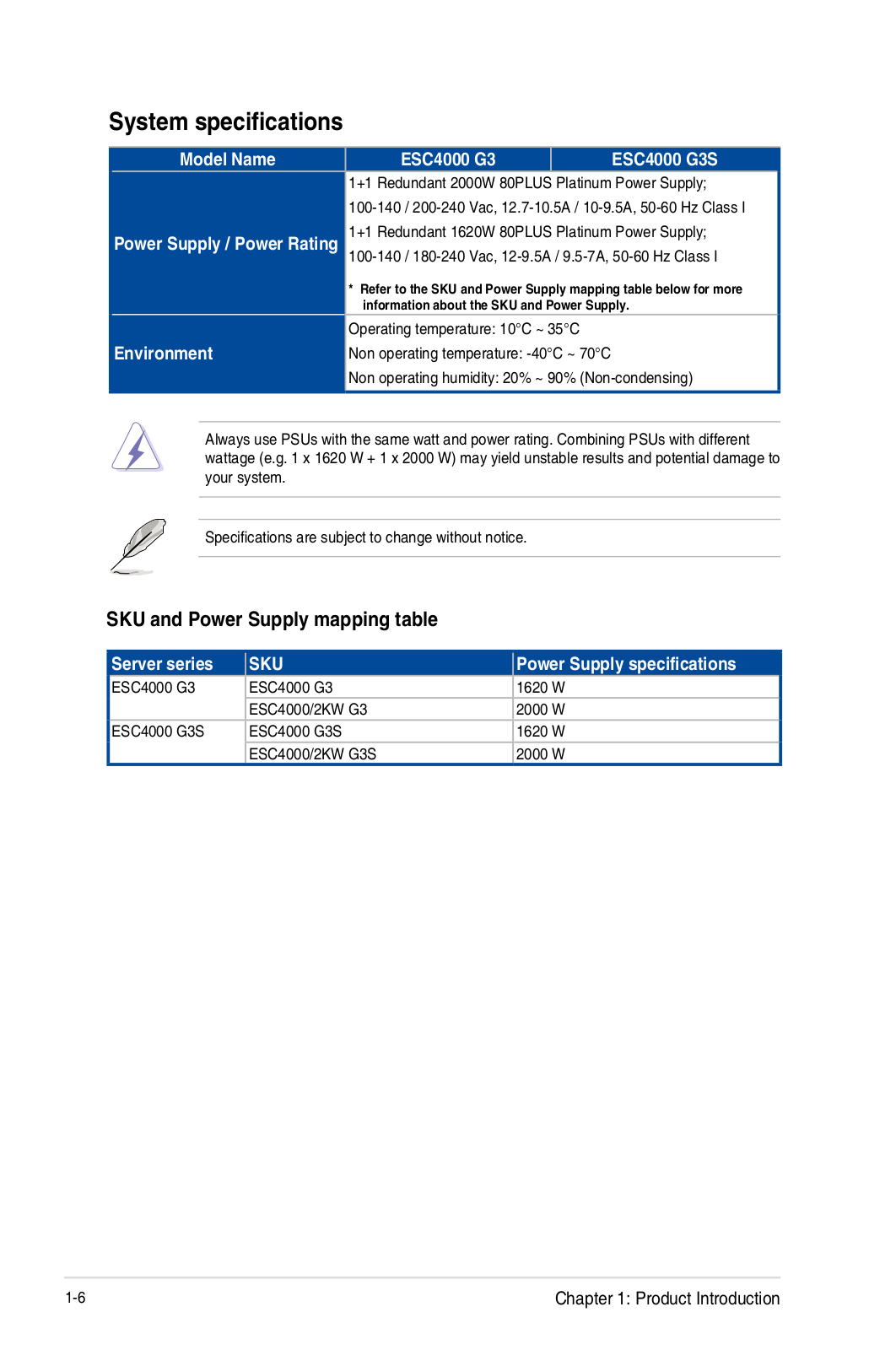
ESC4000
11
ESC4000A-E10
4
ESC4000-FDR
3
ESC4000FDRG2
ESC4000-FDR G2S
3
ESC4000G2
2
ESC4000 G2S
2
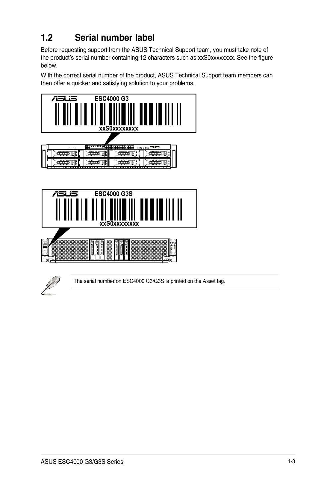
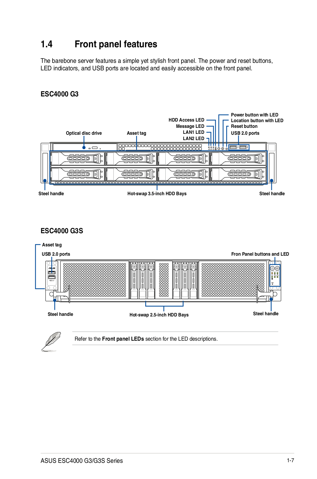
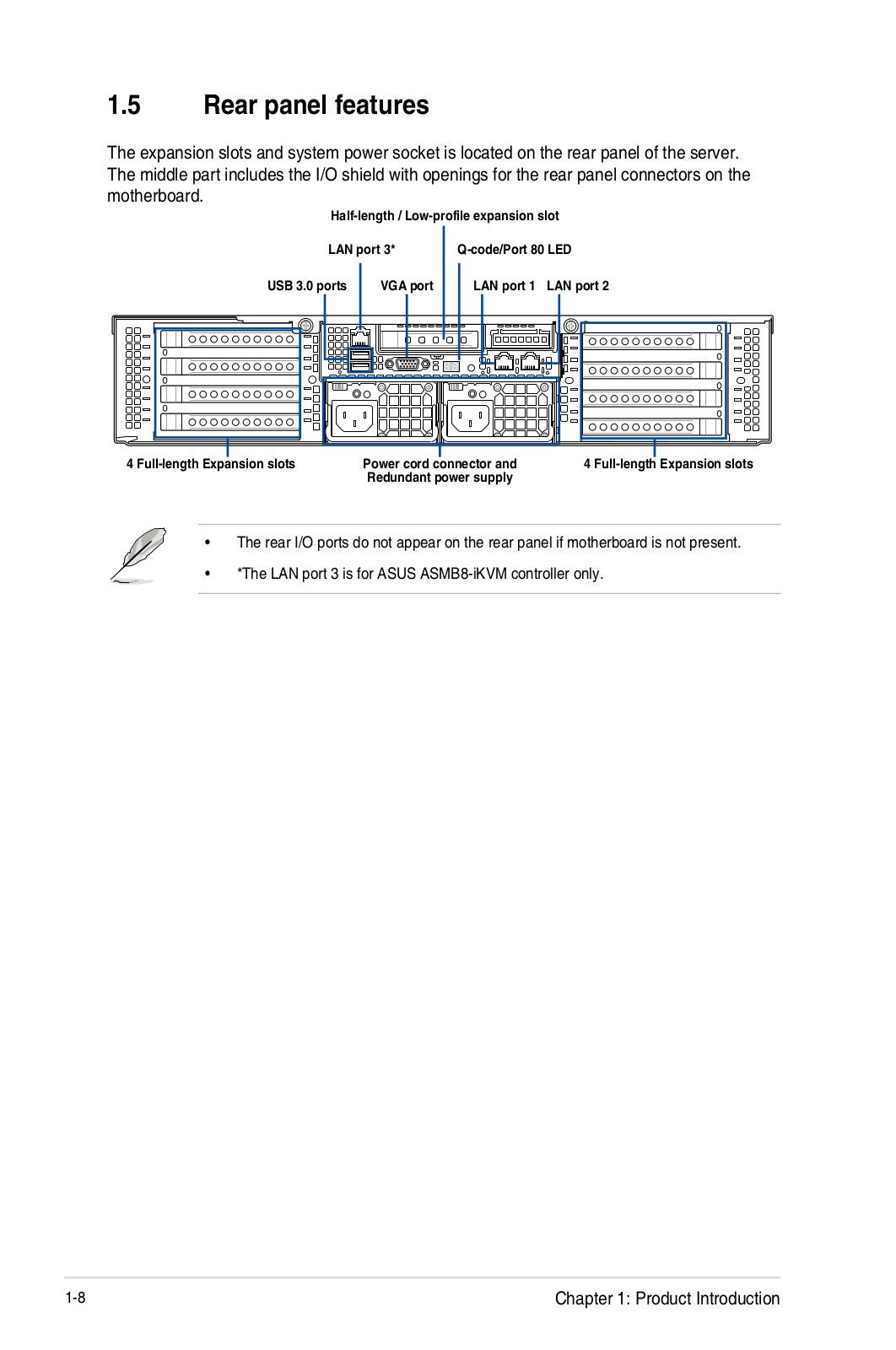
ESC4000 G3
5
ESC4000 G3S
5
ESC4000 G4
ESC4000 G4S
ESC4000/IB
2
ESC500
2
ESC500 G2
3
ESC500 G3
3
ESC500 G4
ESC500 G4-M2V
2
ESC500 G4 SFF
ESC700
ESC700 G2
2
ESC700 G4
ESC8000
ESC8000 G3
3
ESC8000 G4
ESC8000 G4/10G
ESC800 G4
ESEDRW-08-H
Espada GT200
5
Essence III
5
Essence One
2
Essence One Series
Essence STX II
4
Essence STX II 7.1
2
Essentio
9
Essentio CG1330
Essentio CG Series
ESSENTIO CM6730
Essentio CM6830
2
Essentio CP1130
Essentio CP5141
Essentio CP6130
ESSENTIO CP6230
ESSENTIO DESKTOP PC CM1630
ESSENTIO E4712
ET16
30
et1601
ET1602
8
ET1602C
31
ET1605
ET1610
18
ET1610P
15
ET1610 series
ET 16 series
Loading...
Loading...
Nothing found
ESC4000 G3S
Rail Kit Installation Manual
6 pgs
722.28 Kb
0
User Manual
112 pgs
20.34 Mb
0
User Manual
104 pgs
5.86 Mb
1
operation manual
206 pgs
17.95 Mb
0
User’s Manual [zh]
204 pgs
13.44 Mb
0
Table of contents
Loading...
ASUS ESC4000 G3S operation manual
...
ASUS operation manual
Download
Specifications and Main Features
Frequently Asked Questions
User Manual
Download
Loading...
+
176
hidden pages
Unhide
You need points to download manuals.
1 point = 1 manual.
You can buy points or you can get point for every manual you upload.
Buy points
Upload your manuals
 Loading...