

Page 1

ESC4000A-E10
2U Rackmount Server
User Guide
Page 2

E17253
Revised Edition V3
August 2020
Copyright © 2020 ASUSTeK COMPUTER INC. All Rights Reserved.
No part of this manual, including the products and software described in it, may be reproduced, transmitted,
transcribed, stored in a retrieval system, or translated into any language in any form or by any means,
except documentation kept by the purchaser for backup purposes, without the express written permission
of ASUSTeK COMPUTER INC. (“ASUS”).
ASUS provides this manual “as is” without warranty of any kind, either express or implied, including but not
limited to the implied warranties or conditions of merchantability or fitness for a particular purpose. In no
event shall ASUS, its directors, officers, employees, or agents be liable for any indirect, special, incidental,
or consequential damages (including damages for loss of profits, loss of business, loss of use or data,
interruption of business and the like), even if ASUS has been advised of the possibility of such damages
arising from any defect or error in this manual or product.
Specifications and information contained in this manual ae furnished for informational use only, and are
subject to change at any time without notice, and should not be construed as a commitment by ASUS.
ASUS assumes no responsibility or liability for any errors or inaccuracies that may appear in this manual,
including the products and software described in it.
Product warranty or service will not be extended if: (1) the product is repaired, modified or altered, unless
such repair, modification of alteration is authorized in writing by ASUS; or (2) the serial number of the
product is defaced or missing.
Products and corporate names appearing in this manual may or may not be registered trademarks or
copyrights of their respective companies, and are used only for identification or explanation and to the
owners’ benefit, without intent to infringe.
ii
Page 3

Contents
Safety information ...................................................................................................... vi
About this guide ....................................................................................................... viii
Chapter 1: Product Introduction
1.1 System package contents ......................................................................... 1-2
1.2 Serial number label .................................................................................... 1-2
1.3 System specifications ...............................................................................1-3
1.4 Front panel features ...................................................................................1-5
1.5 Rear panel features .................................................................................... 1-5
1.6 Internal features ......................................................................................... 1-6
1.7 LED information ......................................................................................... 1-7
1.7.1 Front panel LEDs ........................................................................1-7
1.7.2 LAN (RJ-45) LEDs ......................................................................1-8
1.7.3 HDD status LEDs ........................................................................1-9
1.7.4 Q-Code/Port 80 status LEDs.....................................................1-10
Chapter 2: Hardware Setup
2.1 Chassis cover ............................................................................................. 2-2
2.1.1 Air duct ........................................................................................2-4
2.2 Central Processing Unit (CPU) .................................................................2-5
2.2.1 Installing the CPU and heatsink ..................................................2-5
2.3 System memory .........................................................................................2-9
2.3.1 Overview ..................................................................................... 2-9
2.3.2 Memory Configurations ...............................................................2-9
2.4 Hard disk drives ....................................................................................... 2-11
2.4.1 Installing the 3.5-inch SATA HDD/SAS HDD ............................ 2-11
2.4.2 Installing the 2.5-inch SSD/SATA HDD/SAS HDD/NVMe.........2-12
2.5 Expansion slots ........................................................................................2-13
2.5.1 The PCI Express riser card .......................................................2-13
2.5.2 Installing an ASUS PIKE II card ................................................2-16
2.5.3 Reconnecting the cable to the M.2 expansion board
(only for SKU-3) ........................................................................ 2-22
2.5.4 Installing an M.2 (NGFF) card ...................................................2-24
2.5.5 Reconnecting the cable to the OCP 3.0 slot baseboard
(only for SKU-2) ........................................................................ 2-25
2.5.6 Configuring an expansion card .................................................2-27
2.6 Cable connections ................................................................................... 2-28
2.7 SATA/SAS backplane cabling ................................................................. 2-29
iii
Page 4

Contents
2.8 Removable/optional components ...........................................................2-30
2.8.1 Cable organizer metal cover .....................................................2-30
2.8.2 System fans ..............................................................................2-31
2.8.3 Redundant power supply units ..................................................2-32
2.8.4 U.2 drives ..................................................................................2-34
2.8.5 Installing Accelerators ...............................................................2-36
Chapter 3: Installation Options
3.1 Friction Rail Kit ...........................................................................................3-2
3.1.1 Attaching the rack rails ...............................................................3-2
Chapter 4: Motherboard Infomation
4.1 KRPG-U8 Motherboard layout ..................................................................4-2
4.2 Jumpers ...................................................................................................... 4-4
4.3 Internal connectors .................................................................................... 4-8
4.4 Onboard LEDs .......................................................................................... 4-16
Chapter 5: BIOS Setup
5.1 Managing and updating your BIOS .......................................................... 5-2
5.1.1 ASUS CrashFree BIOS 3 utility...................................................5-2
5.1.2 ASUS EZ Flash Utility .................................................................5-3
5.1.3 BUPDATER utility .......................................................................5-4
5.2 BIOS setup program .................................................................................. 5-6
5.2.1 BIOS menu screen ......................................................................5-7
5.2.2 Menu bar .....................................................................................5-7
5.2.3 Menu items..................................................................................5-8
5.2.4 Submenu items ...........................................................................5-8
5.2.5 Navigation keys ...........................................................................5-8
5.2.6 General help................................................................................5-8
5.2.7 Configuration fields .....................................................................5-8
5.2.8 Pop-up window............................................................................5-8
5.2.9 Scroll bar .....................................................................................5-8
5.3 Main menu ..................................................................................................5-9
5.3.1 System Date [Day xx/xx/xxxx] .....................................................5-9
5.3.2 System Time [xx:xx:xx] ...............................................................5-9
5.4 Performance Tuning menu ......................................................................5-10
iv
Page 5

Contents
5.5 Advanced menu .......................................................................................5-12
5.5.1 Trusted Computing....................................................................5-12
5.5.2 PSP Firmware Versions ............................................................5-13
5.5.3 APM Configuration ....................................................................5-13
5.5.4 Onboard LAN Configuration .....................................................5-14
5.5.5 Serial Port Console Redirection ................................................5-15
5.5.6 CPU Configuration ....................................................................5-17
5.5.7 PCI Subsystem Settings ...........................................................5-18
5.5.8 USB Configuration ....................................................................5-19
5.5.9 Network Stack Configuration.....................................................5-20
5.5.10 CSM Configuration .................................................................... 5-21
5.5.11 NVMe Configuration .................................................................. 5-22
5.5.12 SATA Configuration .................................................................. 5-22
5.5.13 AMD Mem Configuration Status................................................ 5-23
5.5.14 iSCSI Configuration...................................................................5-23
5.6 Chipset menu ...........................................................................................5-24
5.7 Security menu ..........................................................................................5-25
5.8 Boot menu ................................................................................................5-28
5.9 Tool menu ................................................................................................. 5-29
5.10 Save & Exit menu ..................................................................................... 5-30
5.11 AMD CBS menu ........................................................................................ 5-31
5.11.1 CPU Common Options.............................................................. 5-31
5.11.2 DF Common Options ................................................................ 5-33
5.11.3 UMC Common Option ............................................................... 5-35
5.11.4 NBIO Common Options ............................................................ 5-40
5.11.5 NTB Common Options .............................................................. 5-44
5.12 Event Logs menu ..................................................................................... 5-45
5.12.1 Change Smbios Event Log Settings ......................................... 5-45
5.12.2 View Smbios Event Log ............................................................ 5-46
5.13 Server Mgmt menu ................................................................................... 5-47
Chapter 6: Driver Installation
6.1 Running the Support DVD ......................................................................... 7-2
Appendix
KRPG-U8 block diagram ......................................................................................... A-2
Notices .................................................................................................................... A-3
ASUS contact information ...................................................................................... A-6
v
Page 6
Safety information
Electrical Safety
• Before installing or removing signal cables, ensure that the power cables for the system
unit and all attached devices are unplugged.
• To prevent electrical shock hazard, disconnect the power cable from the electrical outlet
before relocating the system.
• When adding or removing any additional devices to or from the system, ensure that the
power cables for the devices are unplugged before the signal cables are connected. If
possible, disconnect all power cables from the existing system before you add a device.
• If the power supply is broken, do not try to fix it by yourself. Contact a qualified service
technician or your dealer.
Operation Safety
• Any mechanical operation on this server must be conducted by certified or experienced
engineers.
• Before operating the server, carefully read all the manuals included with the server
package.
• Before using the server, ensure all cables are correctly connected and the power cables
are not damaged. If any damage is detected, contact your dealer as soon as possible.
• To avoid short circuits, keep paper clips, screws, and staples away from connectors,
slots, sockets and circuitry.
• Avoid dust, humidity, and temperature extremes. Place the server on a stable surface.
This product is equipped with a three-wire power cable and plug for the user’s safety. Use
the power cable with a properly grounded electrical outlet to avoid electrical shock.
Restricted Access Location
This product is intended for installation only in a Computer Room where:
• Access can only be gained by SERVICE PERSONS or by USERS who have been
instructed about the reasons for the restrictions applied to the location and about any
precautions that shall be taken.
• Access is through the use of a TOOL, or other means of security, and is controlled by
the authority responsible for the location.
CAUTION! This server system is heavy. Ask for assistance when moving or carrying
the system.
vi
Heavy System
Page 7

Lithium-Ion Battery Warning
CAUTION:
same or equivalent type recommended by the manufacturer. Dispose of used batteries
according to the manufacturer’s instructions.
Danger of explosion if battery is incorrectly replaced. Replace only with the
Avertissement sur les batteries Lithium-Ion
ATTENTION :
Remplacer uniquement avec une batterie de type semblable ou équivalent, recommandée
par le fabricant. Jeter les batteries usagées conformément aux instructions du fabricant.
Danger d’explosion si la batterie n’est pas correctement remplacée.
vii
Page 8

About this guide
Audience
This user guide is intended for system integrators, and experienced users with at least basic
knowledge of configuring a server.
Contents
This guide contains the following parts:
1. Chapter 1: Product Introduction
This chapter describes the general features of the server, including sections on front
panel and rear panel specifications.
2. Chapter 2: Hardware Setup
This chapter lists the hardware setup procedures that you have to perform when
installing or removing system components.
3. Chapter 3: Installation Options
This chapter describes how to install optional components into the barebone server.
4. Chapter 4: Motherboard Information
This chapter gives information about the motherboard that comes with the server. This
chapter includes the motherboard layout, jumper settings, and connector locations.
5. Chapter 5: BIOS Setup
This chapter tells how to change system settings through the BIOS Setup menus and
describes the BIOS parameters.
6. Chapter 6: Driver Installation
This chapter provides instructions for installing the necessary drivers for different
system components.
viii
Page 9

Conventions
To ensure that you perform certain tasks properly, take note of the following symbols used
throughout this manual.
DANGER/WARNING: Information to prevent injury to yourself when trying to
CAUTION: Information to prevent damage to the components when trying to
IMPORTANT: Instructions that you MUST follow to complete a task.
NOTE: Tips and additional information to help you complete a task.
complete a task.
complete a task.
Typography
Bold text
Italics
<Key> Keys enclosed in the less-than and greater-than
Example: <Enter> means that you must press the
<Key1>+<Key2>+<Key3> If you must press two or more keys simultaneously,
Example: <Ctrl>+<Alt>+<Del>
Command
Example: At the DOS prompt,
Indicates a menu or an item to select.
Used to emphasize a word or a phrase.
sign means that you must press the enclosed key.
Enter or Return key.
the key names are linked with a plus sign (+).
Means that you must type the command exactly
as shown, then supply the required item or value
enclosed in brackets.
type the command line:
format A:/S
References
Refer to the following sources for additional information, and for product and software
updates.
1. ASUS Control Center (ACC) user guide
This manual tells how to set up and use the proprietary ASUS server management
utility.
2. ASUS websites
The ASUS websites worldwide provide updated information for all ASUS hardware and
software products. Refer to the ASUS contact information.
ix
Page 10

x
Page 11

Chapter 1: Product Introduction
Product Introduction
This chapter describes the general features of the chassis kit. It
includes sections on front panel and rear panel specifications.
1
Page 12
1.1 System package contents
Check your system package for the following items.
ESC4000A-E10
Chassis ASUS 2U Rackmount Chassis
Motherboard ASUS KRPG-U8 Server Board
1 x MB Support DVD
1 x ACC instruction card
1 x Bag of Screws
2 x AC Power Cables
Accessory box
• If any of the above items is damaged or missing, contact your retailer.
• Optional items come bundled if you selected them when purchasing the system and
8 x 6+2-pin VGA Power cables
4 x ASUS CPU 8-pin Power cables
4 x GPU air ducts (for Nvidia/AMD cards)
1 x CPU heatsink
1 x Rail Kit (optional)
cannot be bought separately.
1.2 Serial number label
Before requesting support from the ASUS Technical Support team, you must take note of
the product’s serial number containing 12 characters such as xxS0xxxxxxxx. See the figure
below.
With the correct serial number of the product, ASUS Technical Support team members can
then offer a quicker and satisfying solution to your problems.
1-2
ESC4000A-E10
xxS0xxxxxxxx
The serial number is printed on the Asset tag.
Chapter 1: Product Introduction
Page 13
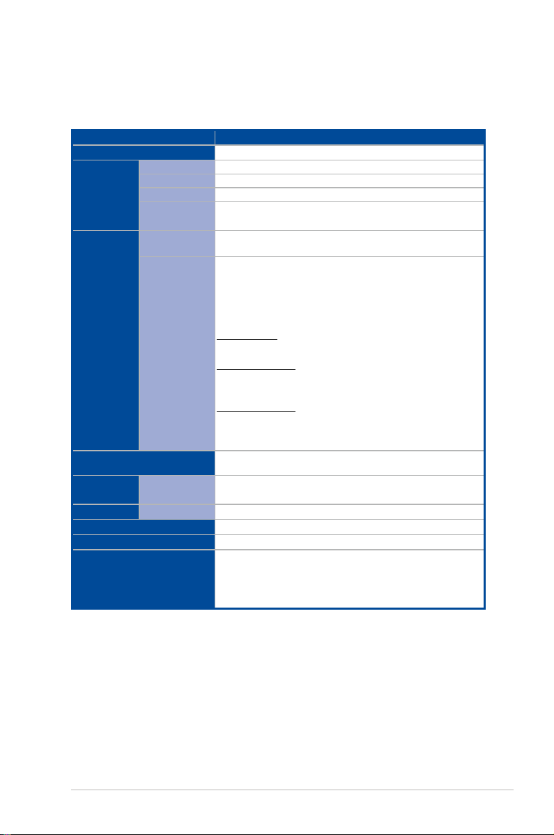
1.3 System specifications
The ASUS ESC4000A-E10 Series servers features the ASUS KRPG-U8 server board that
supports AMD EPYC™ 7002 Series Processor Family.
Model Name ESC4000A-E10
Processor / System Bus
Total Slots
Capacity
Memory
Memory Type
Memory Size
Total PCI/PCI-X/
PCI-E/PIKE Slots
Expansion
Slots
Slot Type
Storage Bays
Networking
Graphic
LAN
VGA
Security
Front I/O ports
Rear I/O ports
AMD EPYC™ 7002 Series Processor Family (up to TDP 280W)
8 (8-channel per CPU, 8 DIMM per CPU)
Up to 2TB
DDR4 3200 RDIMM
256GB, 128GB, 64GB, 32GB, 16GB*
* Please refer to www.asus.com for latest memory AVL update
11
Rear:
- 4 x PCIe x16 slots (Gen4 x16 link, FH,FL) or
8 x PCIe x16 slots (Gen4 x8 link, FH,FL)
- 2 x PCIe x16 slots (Gen4 x16 link, LP,HL)
Front:
SKU-1 (default)
- 1 x PCIe x8 slot (Gen4 x8 link, LP,HL)
SKU-2 (per request)
- 1 x PCIe x8 slot (Gen4 x8 link, LP,HL) or
1 x OCP3.0 slot (Gen4 x8 link) by reconnecting the cables
SKU-3 (per request)
- 1 x PCIe x8 slot (Gen4 x8 link, LP,HL) or
2 x M.2 socket (Gen4 x4 link, up to 22110 module) by
reconnecting the cables
8 x 2.5" or 3.5" Hot-swap Storage Device Bays
(2 x NVMe as default; up to 4 x NVMe Supported)
2 x 1Gb/s LAN ports (Intel
1 x Dedicated management port
AST2500 64MB
TPM2.0
4 x USB 3.2 Gen 1 ports
2 x USB 3.2 Gen 1 ports
2 x Gigabit LAN ports (RJ45)
1 x Management port (RJ45)
1 x VGA port
(continued on the next page)
®
I350-AM2)
ASUS ESC4000A-E10
1-3
Page 14
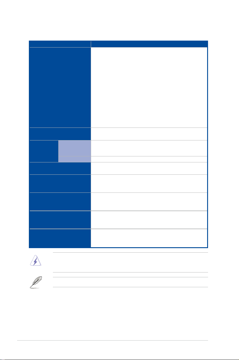
System specifications
Model Name ESC4000A-E10
Switch/LED
OS Support
Out of Band
Management
Solution
Remote
Hardware
Software
Dimension
Net Weight Kg
(CPU, DRAM & HDD not
included)
Gross Weight Kg
(CPU, DRAM & HDD not
included, Packing include)
Power Supply
(following different
configuration by region)
Environment
Front Switch/LED:
1 x Power Switch/LED
1 x Location Switch/LED
1 x HDD Access LED
1 x Message LED
1 x Q-Code/Port 80 LED
2 x LAN LED
Rear Switch/LED:
1 x Power switch/LED
1 x Location LED
1 x Message LED
1 x HDD Access LED
Windows® Server 2019, RedHat® , SuSE®, Ubuntu, Vmware
* Please find the latest OS support from http://www.asus.com/
On-Board ASMB9-iKVM for KVM-over-IP
ASUS Control Center
800mm x 440mm x 88.9mm (2U)
31.50” x 17.22” x 3.46”
34 kg
44 kg
1+1 Redundant 1600W 80 PLUS Platinum Power Supply
1+1 Redundant 2200W 80 PLUS Platinum Power Supply
Operation temperature: 10° ~ 35°
Non operation temperature: -40° ~ 70°
Non operation humidity: 20% ~ 90% ( Non condensing)
1-4
Always use PSUs with the same watt and power rating. Combining PSUs with different
wattage (e.g. 1 x 1600 W + 1 x 2200 W) may yield unstable results and potential damage to
your system.
Specifications are subject to change without notice.
Chapter 1: Product Introduction
Page 15
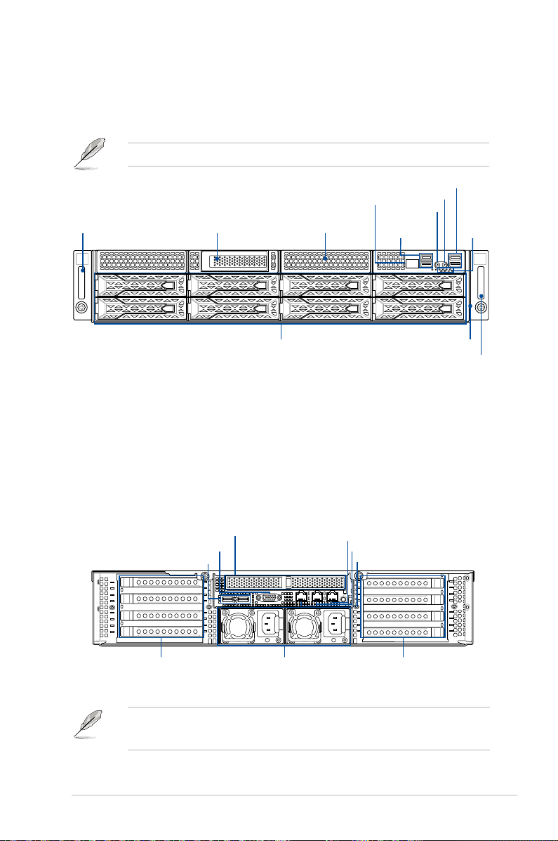
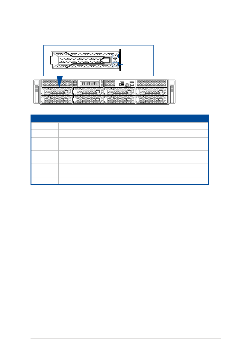
1.4 Front panel features
1
2
The barebone server features a simple yet stylish front panel. The power and location
buttons, LED indicators, and USB ports are located and easily accessible on the front panel.
1.7.1 Front panel LEDs
Hot-swap 3.5-inch storage bays Asset tag
section for the LED descriptions.
Q-code/Port 80 LED
Location button
Power button
USB 3.2 Gen 1
ports
USB 3.2 Gen 1 ports
Front panel
LED
1
2
Steel handle
Steel handle
Refer to the
Half-length / Low-profile expansion slot Expansion card cage
1.5 Rear panel features
The expansion slots and system power socket is located on the rear panel of the server.
The middle part includes the I/O shield with openings for the rear panel connectors on the
motherboard.
Half-length / Low-profile expansion slot
VGA port
USB 3.0 ports
LAN port 2
LAN port 1
DM_LAN1*
4 Full-length Expansion slots
• The rear I/O ports do not appear on the rear panel if motherboard is not present.
• *The DM_LAN1 port is for ASUS ASMB9-iKVM controller only.
ASUS ESC4000A-E10
Power cord connector and
Redundant power supply
4 Full-length Expansion slots
1-5
Page 16
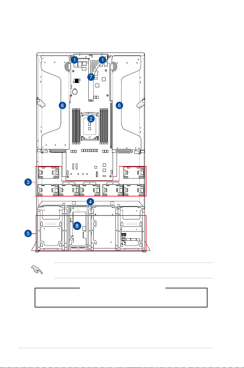
1.6 Internal features
The barebone server includes the basic components as shown.
1. Redundant power
2. ASUS KRPG-U8 server
3. System fans
4. SATA/SAS/U.2
5. Hot-swap Storage
6. PCI-E expansion boards
7. PCI-E x32 slot with
FAN7 FAN6
FAN1FAN2FAN3FAN4FAN5
8. Half-length / Low-profile
supply and power fan
(hidden)
board
backplane
Device bays (SAS,
SATA, and U.2)
(hidden)
butterfly riser card
expansion slot
1-6
A protection film is pre-attached to the front cover before shipping. Please remove the
protection film before turning on the system for proper heat dissipation.
WARNING
HAZARDOUS MOVING PARTS
KEEP FINGERS AND OTHER BODY PARTS AWAY
Chapter 1: Product Introduction
Page 17
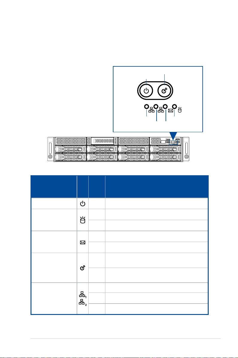
1.7 LED information
1.7.1 Front panel LEDs
LED Icon
Power button with LED
HDD access LED
Message LED
Location button with LED
1
2
LAN2 LED
LAN1 LED
Message LED
HDD Access LED
1
2
Display
status
Power button with LED
Description
ON System power on
OFF No activity
Blinking Data activity
OFF System is normal; no incoming event
ON A hardware monitor event is indicated
Location button with
LED
LAN LEDs
ASUS ESC4000A-E10
OFF Function off
Location switch is pressed (Press the location switch
ON
again to turn off)
OFF No LAN connection
Blinking LAN is transmitting or receiving data
ON LAN connection is present
1-7
Page 18
1
2
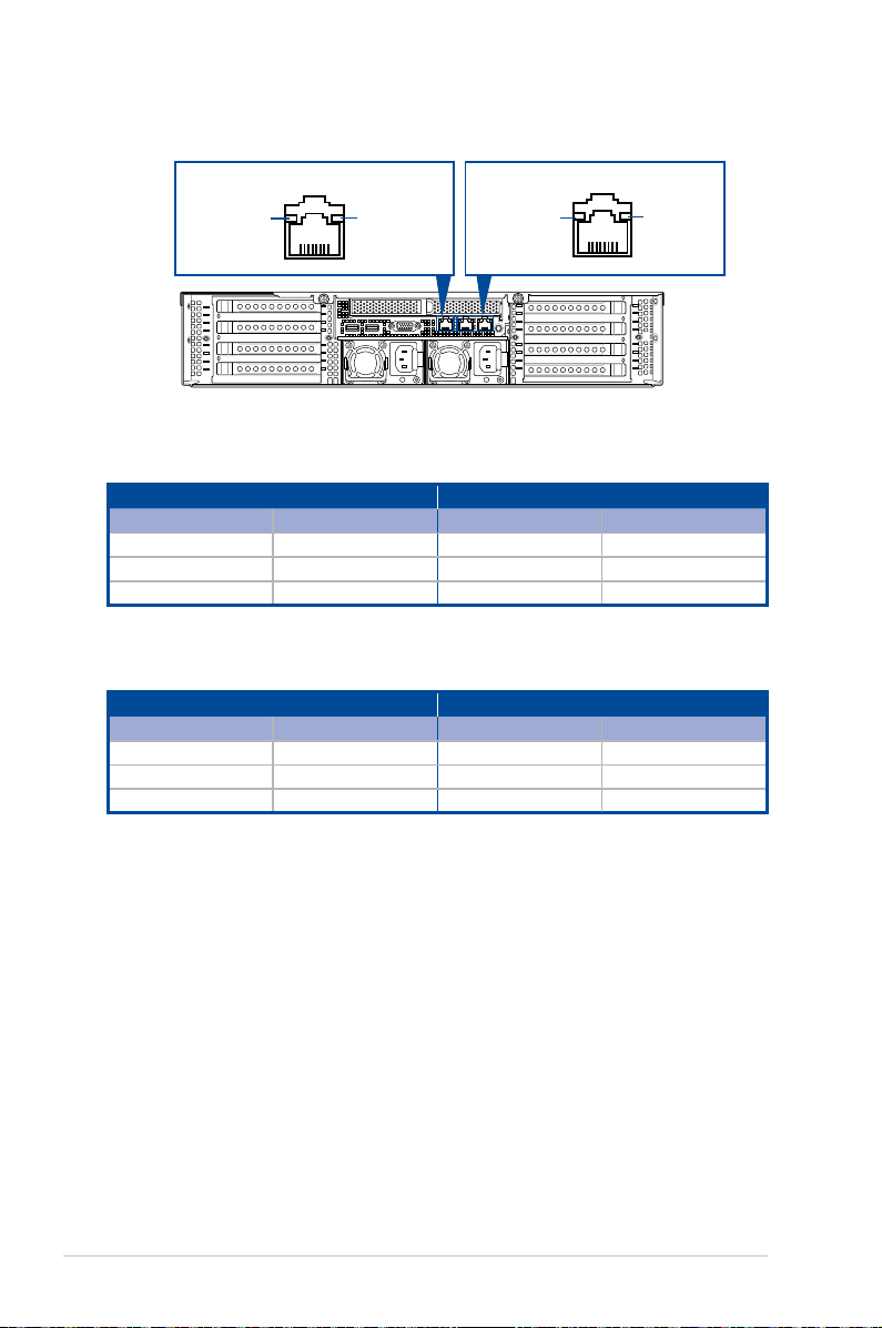
1.7.2 LAN (RJ-45) LEDs
ACT/LINK LED SPEED LED
SPEED LEDACT/LINK LED
LAN1/LAN2 LEDs
ACT/LINK LED SPEED LED
Status Description Status Description
OFF No link OFF 10 Mbps connection
GREEN Linked ORANGE 100 Mbps connection
BLINKING Data activity GREEN 1 Gbps connection
Dedicated Management LAN (for ASMB9 and DM_LAN1)
ACT/LINK LED SPEED LED
Status Description Status Description
OFF No link OFF 10 Mbps connection
ORANGE Linked ORANGE 100 Mbps connection
BLINKING Data activity GREEN 1 Gbps connection
1-8
Chapter 1: Product Introduction
Page 19
1.7.3 HDD status LEDs
Red LED
Green LED
1
2
SATA/SAS HDD LED Description
GREEN ON SATA/SAS HDD power ON
RED ON HDD has failed and should be swapped immediately
GREEN/
RED
GREEN/
RED
GREEN/
RED
GREEN Blinking Read/write data from/into the SATA/SAS HDD
Blinking RAID rebuilding
Blinking Locate
OFF HDD not found
ASUS ESC4000A-E10
1-9
Page 20

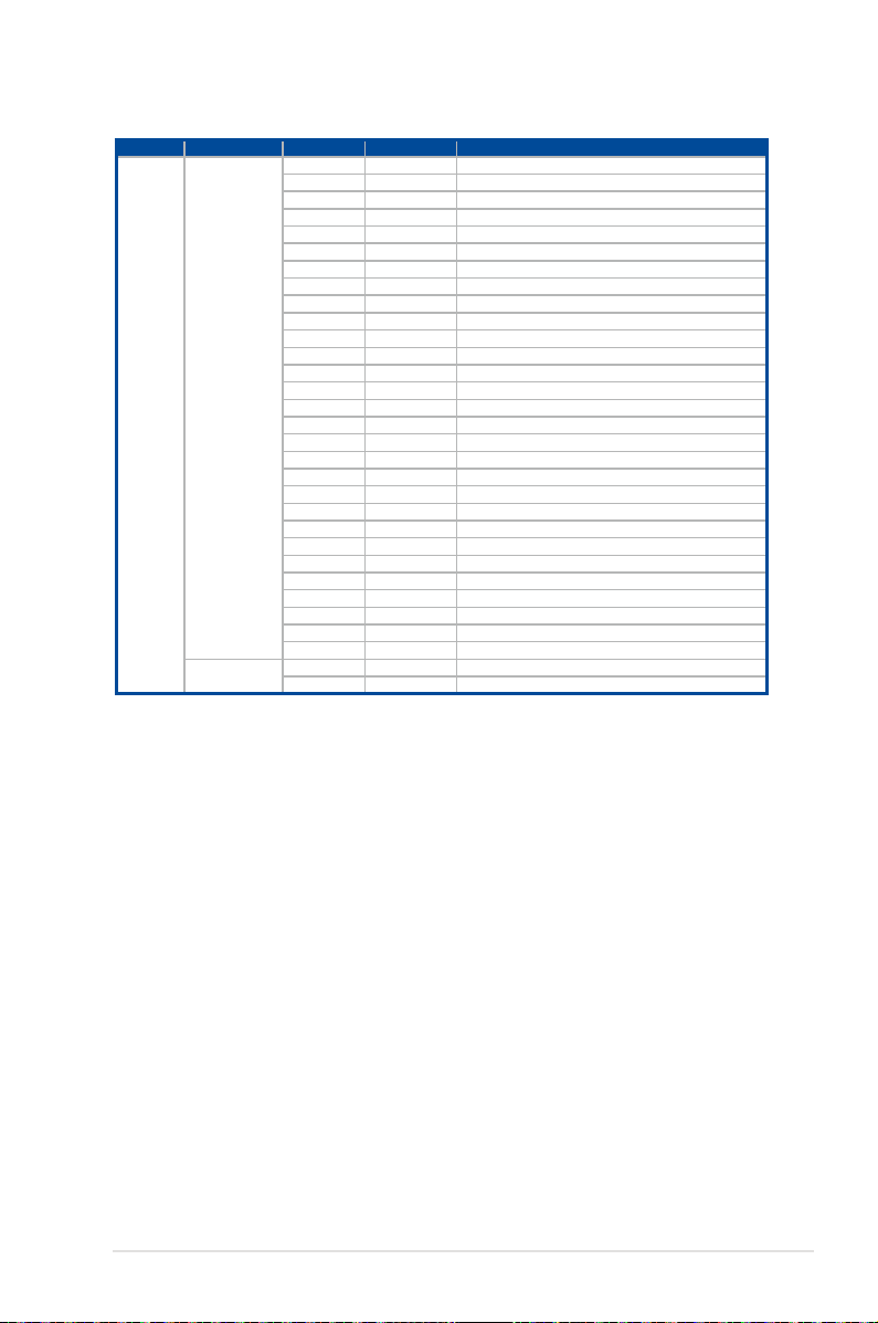
1.7.4 Q-Code/Port 80 status LEDs
The Q-Code LED provides a 2-digit display that shows the status of your system. Refer to the
Q-Code table
Q-Code table
Action PHASE POST CODE TYPE DESCRIPTION
SEC Start up Security Phase
Quick VGA
of this user guide for more information about the 2-digit codes.
0x1 Progress First post code
0x2 Progress Load BSP microcode
0x3 Progress Perform early platform Initialization
0x4 Progress Set cache as ram for PEI phase
0x5 Progress Establish Stack
0x6 Progress CPU Early Initialization
0x10 Progress PEI Core Entry
PEI(Pre-EFI
Initialization) phase
MRC Progress
phase
DXE(Driver
Execution
Environment) phase
0x11 Progress PEI cache as ram CPU initial
0x15 Progress NB Initialization before installed memory
0x19 Progress SB Initialization before installed memory
0xB0 MRC Progress DIMM detect
0xB1 MRC Progress DIMM clock Initialization
0xB2 MRC Progress DIMM SPD data Initialization
0xB3 MRC Progress DIMM global early
0xB4 MRC Progress DIMM rank detect
0xB5 MRC Progress DIMM channel early
0xB6 MRC Progress DIMM DDRIO Initialization
0xB7 MRC Progress DIMM channel training
0xB8 MRC Progress DIMM Initialization throttling
0xB9 MRC Progress memory BIST
0xBA MRC Progress MEM memory Initialization
0xBB MRC Progress DIMM DDR memory map
0xBC MRC Progress RAS configuration
0xBD MRC Progress Get Margins
0xBE MRC Progress Memory SSA api Initialization
0xBF MRC Progress MRC done
0x32 Progress CPU POST-Memory Initialization
0x33 Progress CPU Cache Initialization
0x34 Progress Application Processor(s) (AP) Initialization
0x35 Progress BSP Selection
0x36 Progress CPU Initialization
0x37 Progress Pre-memory NB Initialization
0x3B Progress Pre-memory SB Initialization
0x4F Progress DXE Initial Program Load(IPL)
0x60 Progress DXE Core Started
0x61 Progress DXE NVRAM Initialization
0x62 Progress SB run-time Initialization
0x63 Progress CPU DXE Initialization
0x68 Progress PCI HB Initialization
0x69 Progress NB DXE Initialization
0x6A Progress NB DXE SMM Initialization
0x70 Progress SB DXE Initialization
0x71 Progress SB DXE SMM Initialization
0x72 Progress SB DEVICES Initialization
0x78 Progress ACPI Module Initialization
0x79 Progress CSM Initialization
0xD0 Progress CPU PM Structure Initialization
0xD1 Progress CPU PM CSR programming
0xD2 Progress CPU PM MSR programming
0xD3 Progress CPU PM PSTATE transition
0xD4 Progress CPU PM driver exit
0xD5 Progress CPU PM On ready to boot event
(continued on the next page)
1-10
Chapter 1: Product Introduction
Page 21
Q-Code table
Action PHASE POST CODE TYPE DESCRIPTION
BDS(Boot Device
Selection) phase
Normal boot
Operating system
phase
0x90 Progress BDS started
0x91 Progress Connect device event
0x92 Progress PCI Bus Enumeration
0x93 Progress PCI Bus Enumeration
0x94 Progress PCI Bus Enumeration
0x95 Progress PCI Bus Enumeration
0x96 Progress PCI Bus Enumeration
0x97 Progress Console outout connect event
0x98 Progress Console input connect event
0x99 Progress AMI Super IO start
0x9A Progress AMI USB Driver Initialization
0x9B Progress AMI USB Driver Initialization
0x9C Progress AMI USB Driver Initialization
0x9D Progress AMI USB Driver Initialization
0xb2 Progress Legacy Option ROM Initialization
0xb3 Progress Reset system
0xb4 Progress USB hotplug
0xb6 Progress NVRAM clean up
0xb7 Progress NVRAM configuration reset
0xA0 Progress IDE, AHCI Initialization
0xA1 Progress IDE, AHCI Initialization
0xA2 Progress IDE, AHCI Initialization
0xA3 Progress IDE, AHCI Initialization
0x00~0xFF Progress Wait BMC ready
0xA8 Progress BIOS Setup Utility password verify
0xA9 Progress BIOS Setup Utility start
0xAB Progress BIOS Setup Utility input wait
0xAD Progress Ready to boot event
0xAE Progress Legacy boot event
0xAA Progress APIC mode
0xAC Progress PIC mode
ASUS ESC4000A-E10
1-11
Page 22

1-12
Chapter 1: Product Introduction
Page 23

Chapter 2: Hardware Setup
Hardware Setup
This chapter lists the hardware setup procedures that you have
to perform when installing or removing system components.
2
Page 24
2.1 Chassis cover
There are three parts of the chassis cover you may remove.
The diagrams in this section are for reference only. The system layout may vary with
models, but the installation steps are the same for all models.
To remove the rear chassis cover:
1. Release the two (2) thumbscrews on the rear of the chassis.
2. Push and hold the cover buttons down, then slide the chassis cover towards the rear to
disengage it from the chassis.
3. Lift the chassis cover to completely remove it from the chassis.
2-2
2
1
Chapter 2: Hardware Setup
Page 25
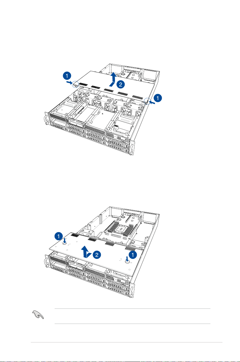
To remove the middle chassis cover:
1. Press the cover latches down on both sides of the middle chassis cover.
2. Lift the chassis cover to completely remove it from the chassis.
2
1
To remove the front chassis cover:
1. Push and hold the cover buttons down, then slide the chassis cover towards the front
to disengage it from the chassis.
2. Lift the chassis cover to completely remove it from the chassis.
A protection film is pre-attached to the system cover before shipping. Please remove the
protection film before turning on the system for proper heat dissipation.
ASUS ESC4000A-E10
2
1
2-3
Page 26
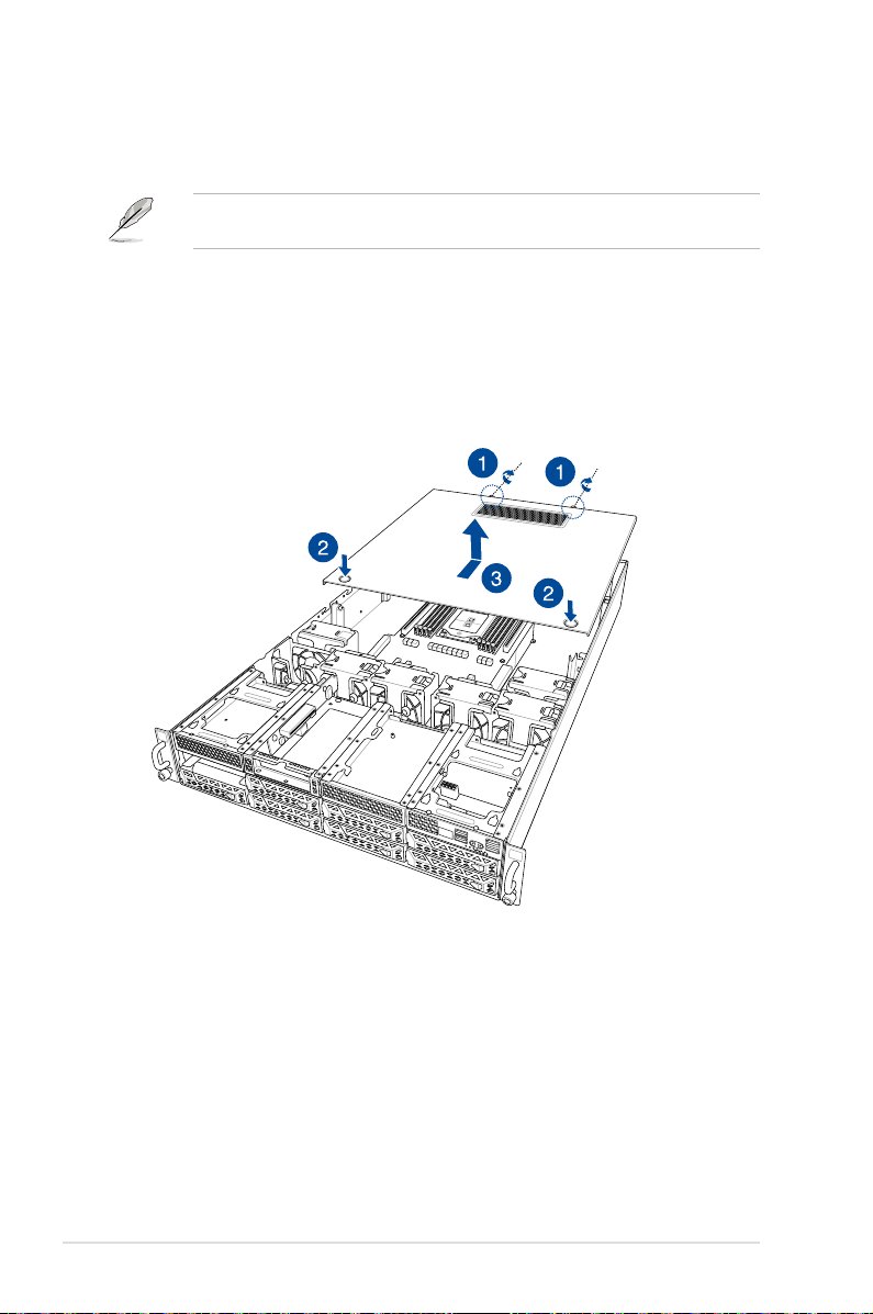
2.1.1 Air duct
The diagrams in this section are for reference only. The system layout may vary with
models, but the installation steps are the same for all models.
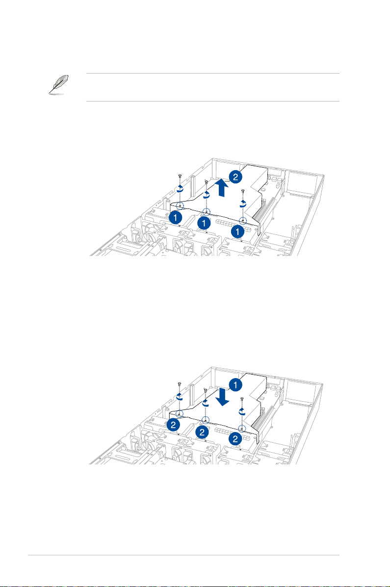
To remove the air duct:
1. Remove the three screws as shown.
2. Lift the air duct to remove it from the chassis.
To reinstall the air duct:
1. Align and replace the air duct to the chassis ensuring that the screw holes on the air
duct match the screw holes on chassis.
2. Secure the air duct to the chassis with three screws.
2-4
Chapter 2: Hardware Setup
Page 27
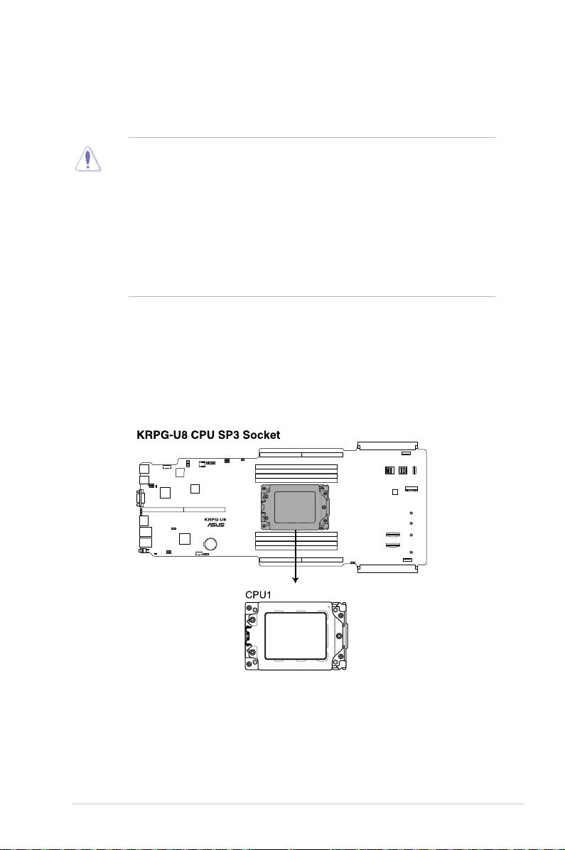
2.2 Central Processing Unit (CPU)
The motherboard comes with a surface mount Socket SP3 socket designed for the AMD
EPYC™ 7002 Series Family processors.
• Upon purchase of the motherboard, ensure that the PnP cap is on the socket and
the socket contacts are not bent. Contact your retailer immediately if the PnP cap
is missing, or if you see any damage to the PnP cap/socket contacts/motherboard
components. ASUS will shoulder the cost of repair only if the damage is shipment/
transit-related.
• Keep the cap after installing the motherboard. ASUS will process Return Merchandise
Authorization (RMA) requests only if the motherboard comes with the cap on the
InSocket SP3
• The product warranty does not cover damage to the socket contacts resulting from
incorrect CPU installation/removal, or misplacement/loss/incorrect removal of the PnP
cap.
2.2.1 Installing the CPU and heatsink
1. Remove the rear chassis cover. For more information, see the section
2. Remove the air duct. For more information, see the section
Air Duct
3. Locate the CPU socket on the motherboard.
Chassis cover
.
.
ASUS ESC4000A-E10
2-5
Page 28
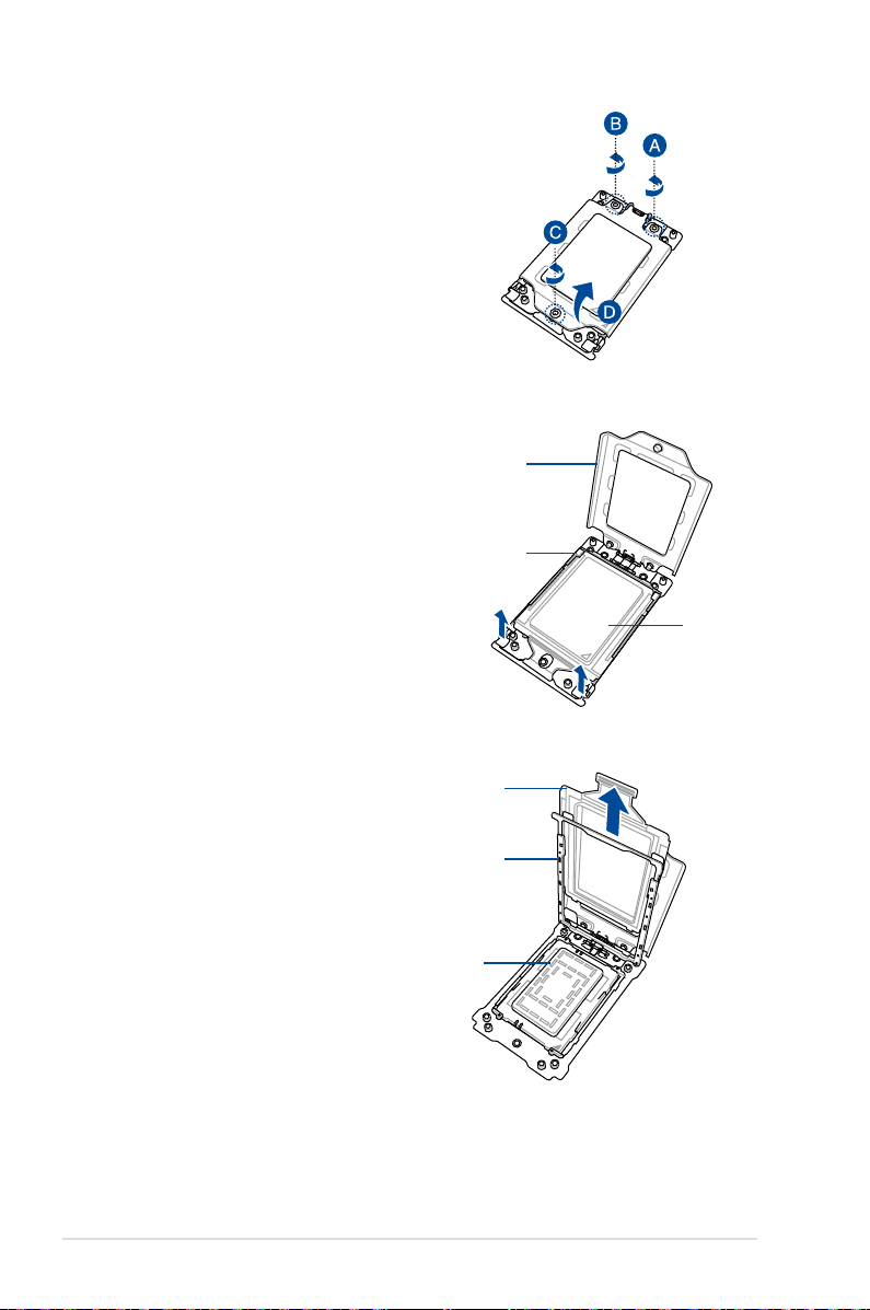
4. Loosen each screw one by one in the
sequence shown on the socket to open
the load plate.
5. Slightly lift open the rail frame.
6. Slide the external cap out of the rail
frame.
Load plate
Rail frame
External cap
External cap
Rail frame
PnP cap
2-6
Chapter 2: Hardware Setup
Page 29
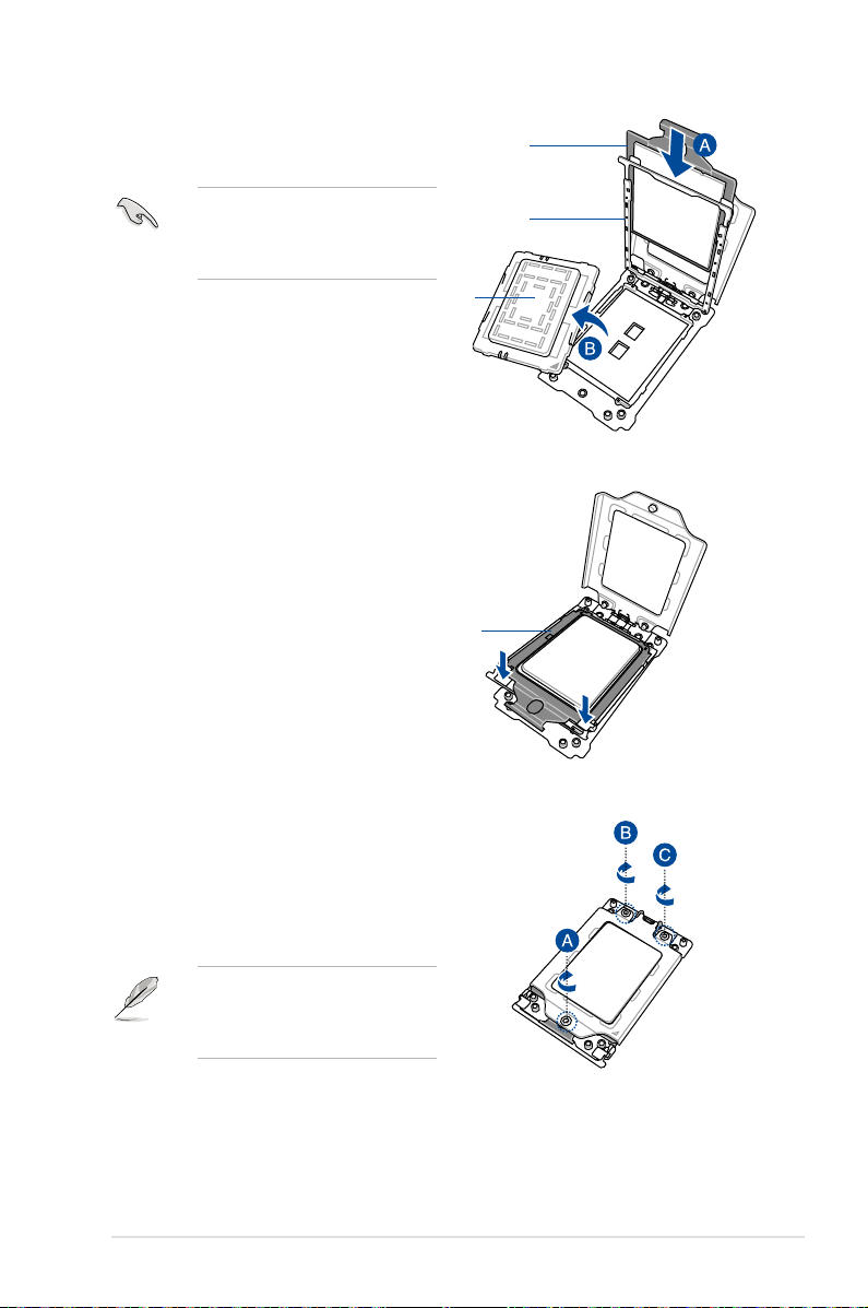
7. Slide the carrier frame with CPU into the
rail frame, then remove the PnP cap.
Carrier frame
with CPU
The carrier frame with CPU fits in only
one correct orientation. DO NOT force
the carrier frame with CPU into the
rail frame.
PnP cap
8. Gently push the rail frame just enough
to let it sit on top of the CPU socket.
Carrier frame
with CPU
Rail frame
9. Close the load plate just enough to let
it sit on top of the CPU, then secure
each screw one by one in the sequence
shown on the socket to completely
secure the load plate.
The load plate screws are
T20 models. A torque value of
16.1±1.2 kgf-cm (14.0±1.0 lbf-in) is
recommended.
ASUS ESC4000A-E10
2-7
Page 30
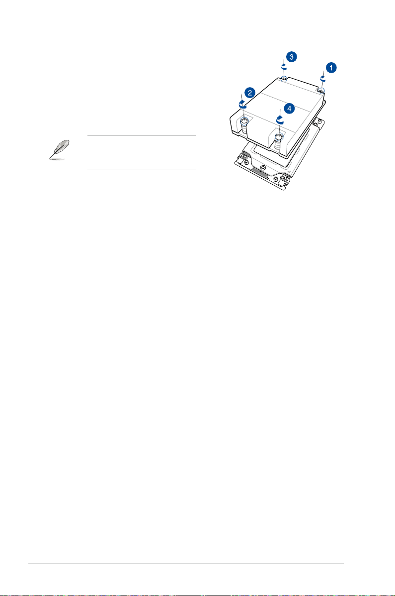
10. Twist each of the four screws with a
screwdriver in the order shown in the
illustration just enough to attach the
heatsink to the motherboard. When the
four screws are attached, tighten them
one by one in a the same diagonal
sequence to completely secure the
heatsink.
The heatsink screws are T20 models.
A torque value of 16.1±1.2 kgf-cm
(14.0±1.0 lbf-in) is recommended.
11. Reinstall the air duct. For more information, see the section
Air Duct
.
2-8
Chapter 2: Hardware Setup
Page 31

2.3 System memory
2.3.1 Overview
The motherboard comes with eight (8) Double Data Rate 4 (DDR4) Dual Inline Memory
Modules (DIMM) sockets.
The figure illustrates the location of the DDR4 DIMM sockets:
2.3.2 Memory Configurations
You may install 16 GB, 32 GB, 64 GB, 128 GB, 256 GB DDR4 RDIMMs into the DIMM sockets
using the memory configurations in this section.
• Refer to ASUS Server AVL for the updated list of compatible DIMMs.
• Always install DIMMs with the same CAS latency. For optimum compatibility, it is
recommended that you obtain memory modules from the same vendor.
• Start installing the DIMMs into the second slots (such as DIMM_A2 , DIMM_B2, etc.)
1 CPU Configuration
A1 B1 C1 D1 E1 F1 G1 H1
1 DIMM •
2 DIMMs • •
4 DIMMs • • • •
8 DIMMs • • • • • • • •
ASUS ESC4000A-E10
2-9
Page 32

2.3.3 Installing a DIMM on a single clip DIMM socket
1. Press the retaining clip outward to unlock
DIMM notch
a DIMM socket.
2. Align a DIMM on the socket such that the
notch on the DIMM matches the DIMM
slot key on the socket.
A DIMM is keyed with a notch so that it fits in only one direction. DO NOT force a DIMM into
a socket in the wrong direction to avoid damaging the DIMM.
3. Hold the DIMM on both ends, then insert
the DIMM vertically into the socket.
Apply force to both ends of the DIMM
simultaneously until the retaining clip
snaps back into place, and the DIMM
cannot be pushed in any further to ensure
proper sitting of the DIMM.
Always insert the DIMM into the socket VERTICALLY to prevent damage to the DIMM notch.
• To install two or more DIMMs, refer to the user guide bundled in the motherboard package.
• Refer to www.asus.com for vendor lists of the memory modules.
DIMM slot key
Unlocked retaining clip
Locked Retaining Clip
Removing a DIMM from a single clip DIMM socket
1. Press the retaining clip outward to unlock
the DIMM.
2. Remove the DIMM from the socket.
Support the DIMM lightly with your fingers when pressing the retaining clips. The DIMM might
get damaged when it flips out with extra force.
2-10
Chapter 2: Hardware Setup
Page 33

2.4 Hard disk drives
The ESC4000-E10 system supports 3.5-inch and 2.5-inch SATA/SAS hard disk drives, or U.2
drives.
2.4.1 Installing the 3.5-inch SATA HDD/SAS HDD
1. Press the spring lock.
2. Pull the tray lever outwards to remove
the drive tray.
3. Prepare the SATA/SAS HDD then place
the 3.5” storage device into the tray until
it clicks into place.
4. Push the drive tray and HDD assembly
all the way into the depth of the bay
until the tray lever and spring lock clicks
and secures the drive tray in place.
• When installed, the SATA/SAS connector on the drive connects to the SATA/SAS
interface on the backplane.
• The drive tray is correctly placed when its front edge aligns with the bay edge.
5. Repeat steps 1 to 4 to install the other SATA/SAS HDDs.
ASUS ESC4000A-E10
2-11
Page 34

2.4.2 Installing the 2.5-inch SSD/SATA HDD/SAS HDD/NVMe
The NVMe drives may be installed in storage device bays 5, 6, 7, and 8 as shown in the
illustration below:
• The default storage device bays to install NVMe drives are storage device bays 7 and 8.
• Support for NVMe drives for storage device bays 5 and 6 is optional, please refer to
2.8.3 U.2 drives (optional)
section
bays 5 and 6.
before installing a NVMe drive to storage device
1
2
Storage device bay 5 and 6
1. Remove the drive tray.
Refer to section
removing the drive tray.
2.4.1 Installing the 3.5-inch SATA HDD/SAS HDD
2. Prepare the SSD/SATA HDD/SAS HDD/
NVMe and the bundled set of screws.
3. Place the SSD/SATA HDD/SAS HDD/
NVMe into the tray (A) then secure it
with four screws (B).
Ensure to take note of the tool-less
notch as it may interfere when trying to
align the screw holes. Press the SSD/
SATA HDD/SAS HDD/NVMe down
on the notch if you are experiencing
issues trying to align the screw holes.
4. Replace the drive tray.
Refer to section
replacing the drive tray.
2.4.1 Installing the 3.5-inch SATA HDD/SAS HDD
Storage device bay 7 and 8
(default NVMe)
for the steps on
for the steps on
5. Repeat steps 1 to 4 to install additional SSD/SATA HDD/SAS HDD/NVMe.
2-12
Chapter 2: Hardware Setup
Page 35

2.5 Expansion slots
Ensure to unplug the power cord before adding or removing expansion cards. Failure to do
so may cause you physical injury and damage motherboard components.
2.5.1 The PCI Express riser card
The onboard PCI Express slot on the motherboard comes pre-installed with a riser card that
supports two x16 slot (x16 Gen4 link) for installing PCI-E x16 low profile cards.
PCI-E x16 slot low-profile
PCI-E x16 slot low-profile
To install PCI-E expansion cards to the riser card:
1. Remove the two (2) screws that secure the riser card to the chassis.
2. Firmly hold the riser card then pull it up to detach it from the PCI Express x32 slot on
the motherboard.
ASUS ESC4000A-E10
2-13
Page 36

3. Remove the two (2) screws from the metal brackets on the riser card (A), then remove
the metal brackets from the riser card (B).
4. Prepare the expansion cards.
Before installing an expansion card, read the documentation that came with it and ensure to
make the necessary hardware settings.
5. Align and insert the golden finger connectors of the expansion cards to the PCI-E slot
connectors on the riser card as shown.
6. Secure the expansion cards with the screws removed earlier.
Riser card
PCI-E x16 expansion card (low-profile)
PCI-E x16 slot (low-profile)
2-14
PCI-E x16 slot (low-profile)
PCI-E x16 expansion
card (low-profile)
Chapter 2: Hardware Setup
Page 37

7. Align and insert the riser card and expansion card assembly into the PCI-E slot on the
motherboard.
The expansion card fits in one orientation only. If it does not fit, try reversing it.
8. Secure the riser card with the two (2) screws that you removed earlier in step 1.
riser card and expansion card assemblyPCI-E slot
ASUS ESC4000A-E10
2-15
Page 38

2.5.2 Installing an ASUS PIKE II card
You may install an ASUS PIKE II card to the internal SAS/HBA/Storage bracket located in the
front of the system.
1. Remove the two (2) default slimline SAS cables from the internal SAS/HBA/Storage
bracket.
2. Remove the screw from the bracket (A), then push the internal SAS/HBA/Storage
bracket towards the rear to remove the internal SAS/HBA/Storage bracket (B).
2-16
Chapter 2: Hardware Setup
Page 39

3. Remove the screw from the metal bracket
(A), then remove the metal bracket.
4. Prepare the ASUS PIKE II card.
5. Remove the two screws on the ASUS PIKE II
card (A), then remove the card bracket (B).
6. Secure the ASUS PIKE II card and the metal
cover (internal SAS/HBA/Storage bracket)
with the two screws.
7. Insert the ASUS PIKE II card into the internal
SAS/HBA/Storage bracket, then secure it
with a screw.
Card bracket
Metal cover
ASUS ESC4000A-E10
2-17
Page 40

8. Connect the two (2) slimline SAS cables from the internal SAS/HBA/Storage bracket
previously earlier.
9. Install the internal SAS/HBA/Storage bracket and secure it with the screw removed
earlier.
10. Remove the three (3) cables on the Cache Vault Power Module clip holder (A), then
release the two (2) screws on the Cache Vault Power Module clip holder (B).
2-18
2
1
Chapter 2: Hardware Setup
Page 41

11. From the back of the Cache Vault Power Module clip holder, push the Cache Vault
Power Module clip holder out of the server system.
2
1
12. Align the three screw holes on the Cache
Vault Power Module clip to the three
screw holes on the Cache Vault Power
Module clip holder, then secure the clip
with the bundled three (3) screws and
three (3) bundled nuts.
13. Align and install the Cache Vault Power
Module into the Cache Vault Power
Module clip.
ASUS ESC4000A-E10
2-19
Page 42

14. Insert the Cache Vault Power Module clip holder into the server system (A), then
connect the bundled extension cable to the cable from the Cache Vault Power Module
(B) and cable from the Cache Vault Flash Module (C).
2
1
15. Reconnect the three (3) cables to the Cache Vault Power Module clip holder, ensure
that the cables are not placed on top of the Cache Vault Power Module.
2-20
2
1
Chapter 2: Hardware Setup
Page 43

16. Secure the Cache Vault Power Module clip holder with the two (2) screws that you
removed earlier in step 10.
2
1
ASUS ESC4000A-E10
2-21
Page 44

2.5.3 Reconnecting the cable to the M.2 expansion board
(only for SKU-3)
You may reconnect the cables to enable the M.2 expansion board located in the front of the
system.
The cables are connected by default if your system package comes with the M.2 expansion
board pre-installed.
1. (optoinal) Remove the two (2) slimline SAS cables from the internal riser board for
PCIe slot, if your system comes with the slimline SAS cables connected.
2. Connect the two (2) slimline SAS cables removed from the internal riser board for PCIe
slot to your M.2 expansion board.
2-22
Chapter 2: Hardware Setup
Page 45

3. Connect the black 4-pin power connector to the 4-pin power connector on the M.2
1
2
1
2
1
2
1
2
1
2
expansion board.
ASUS ESC4000A-E10
2-23
Page 46

2.5.4 Installing an M.2 (NGFF) card
You may install an M.2 card (supports up to 22110) to the onboard M.2 (NGFF) slot on the
motherboard.
1. Locate the M.2 connector (NGFF1) on the motherboard.
2. Remove the screw on the stand screw.
3. Prepare the M.2 card, then align and insert the M.2 card into the M.2 connector (NGFF1).
4. Secure the M.2 card with the screw you removed in step 2.
2-24
Chapter 2: Hardware Setup
Page 47

2.5.5 Reconnecting the cable to the OCP 3.0 slot baseboard
(only for SKU-2)
You may reconnect the cables to enable the OCP3.0 slot baseboard located in the front of
the system.
The cables are connected by default if your system package comes with the OCP3.0 slot
baseboard pre-installed.
1. (optoinal) Remove the two (2) slimline SAS cables from the internal riser board for
PCIe slot, if your system comes with the slimline SAS cables connected.
2. Connect two (2) slimline SAS cables to the two connectors to the left on your OCP3.0
slot baseboard.
ASUS ESC4000A-E10
2
1
2-25
Page 48

3. Connect the white 4-pin power connector to the 4-pin power connector on the OCP3.0
1
2
1
2
1
2
1
2
1
2
slot baseboard.
2
1
2-26
Chapter 2: Hardware Setup
Page 49

2.5.6 Configuring an expansion card
After installing the expansion card, configure it by adjusting the software settings.
1. Turn on the system and change the necessary BIOS settings, if any. See Chapter 5 for
information on BIOS setup.
2. Assign an IRQ to the card. Refer to the
more information.
3. Install the software drivers for the expansion card.
Standard Interrupt assignments
IRQ Priority Standard function
0 1 System Timer
1 2 Keyboard Controller
2 - Programmable Interrupt
3* 11 Communications Port (COM2)
4* 12 Communications Port (COM1)
5* 13 --
6 14 Floppy Disk Controller
7* 15 --
8 3 System CMOS/Real Time Clock
9* 4 ACPI Mode when used
10* 5 IRQ Holder for PCI Steering
11* 6 IRQ Holder for PCI Steering
12* 7 PS/2 Compatible Mouse Port
13 8 Numeric Data Processor
14* 9 Primary IDE Channel
15* 10 Secondary IDE Channel
Standard Interrupt assignments
table for
* These IRQs are usually available for ISA or PCI devices.
ASUS ESC4000A-E10
2-27
Page 50

2.6 Cable connections
HDDLED1
• The bundled system cables are pre-connected before shipment. You do not need to
disconnect these cables unless you remove the pre-installed components to install
additional devices.
• If you need to remove pre-connected system cables please ensure to remove the
cable organizer metal cover beforehand.
• Refer to Chapter 4 for detailed information on the connectors.
MESLED1
LAN_SW2
Lithium Cell
CMOS Power
LOCLED1
IPMI_SW1
KRPG-U8
PWR_SW1
CLRTC1
SBPWR1
LAN_SW1
COM1
VGA1
USB3_2DM_LAN1LAN1LAN2 USB3_1
VGA_SW1
BMC_DEBUGUART1
BMCLED1
PCIE5 PCIE6
ASPEED
AST2500
OCP_SIDE1
MSD1
SPI1
Super
I/O
FU3
TPM1
DM_IP_SEL1
BMC_EN1
INTRUSION1
DDR4 DIMM_D1 (64bit, 288-pin module)
DDR4 DIMM_C1 (64bit, 288-pin module)
DDR4 DIMM_B1 (64bit, 288-pin module)
DDR4 DIMM_A1 (64bit, 288-pin module)
PCIE3 PCIE4
SMART_PSU1
SLIMPCIE2
PWR1
FRNT_FAN7
CPU1
SLIMPCIE1
22422260228022110
DDR4 DIMM_E1 (64bit, 288-pin module)
DDR4 DIMM_F1 (64bit, 288-pin module)
ASM
1074
NGFF1
SLIMUSB1
DDR4 DIMM_G1 (64bit, 288-pin module)
DDR4 DIMM_H1 (64bit, 288-pin module)
PCIE1 PCIE2
ISATA2
PWR2
ISATA1
FRNT_FAN6
Pre-connected system cables
1. SSI power connector (from the power distribution board to the motherboard)
2. ISATA connectors (from motherboard to SATA/SAS/U.2 backplane board)
3. Slim USB connector (from the motherboard to front I/O board)
4. SLIMPCIE2 connector (from motherboard to SATA/SAS/U.2 backplane board)
5. SLIMPCIE1 connector (from motherboard to internal riser board for PCIe slot)
6. System fan connectors (from motherboard FRNT_FAN6, and FRNT_FAN7 to system
fans)
2-28
Chapter 2: Hardware Setup
Page 51

2.7 SATA/SAS backplane cabling
connect to SLIMPCIE1 on the motherboard to support 2
NVMe devices
connect to mini-SAS HD connectors 1 and 2 on the
motherboard. With two mini-SAS HD cables connected, a
total number of 8 SAS/SATA HDDs can be supported
connects to the system fans
* Ensure to connect the corresponding 8-pin plugs to PWR1 and FAN_PWR1 as shown below:
PWR1 FAN_PWR1
red
yellow yellow
black
black
ASUS ESC4000A-E10
2-29
Page 52

2.8 Removable/optional components
You may need to remove previously installed system components when installing or removing
system devices, or when installing optional components into the system. This section tells
how to remove/install the following components:
1. Cable organizer metal cover
2. System fans
3. Redundant power supply units
4. U.2 drives
5. Accelerators
Ensure that the system is turned off before removing any components.
2.8.1 Cable organizer metal cover
When you need to organize the cables connecting from the rear to the front of the system,
you may need to remove the cable organizer metal cover beforehand.
1. Locate the cable organizer metal cover in between the system fans.
2. Pull the cable organizer metal cover upwards to remove it from the system.
3. Once you have finished organizing the cables, ensure to replace the cable organizer
metal cover.
2-30
Chapter 2: Hardware Setup
Page 53

2.8.2 System fans
To uninstall the system fans:
1. Hold the system fan by the notches (A),
then press the latch inwards (B) to release
the system fan from the fan cage.
2. Lift the fan then set it aside.
3. Repeat steps 1 to 2 to uninstall the other
system fans.
To reinstall the system fans:
1. Insert the fan into the fan cage. Ensure the
fan connector is seated firmly within the
cable holder.
ASUS ESC4000A-E10
cable holder
2-31
Page 54

2.8.3 Redundant power supply units
We recommend that you use both of your hands in performing the following steps.
To replace a power supply unit (PSU):
1. Lift up the PSU lever.
2. Hold the PSU lever, press the PSU latch (A) then carefully pull the PSU out of the
system chassis (B).
PSU lever
3. Prepare the replacement PSU.
4. Align and insert the replacement PSU into the empty PSU bay until it clicks in place.
Replacement PSU
2-32
Chapter 2: Hardware Setup
Page 55

• The system automatically combines the two power supply modules as a single one.
The combined output power varies with input voltages. Refer to the table below for
details.
1600W
Input Voltage Max. Output Power (Watt) per PSU
100V-127Vac, 13A, 50-60Hz
100V-127Vac, 12.9A, 47-63Hz
200V-240Vac, 9.5A, 50-60Hz
200V-240Vac, 9.5A, 47-63Hz
2200W
1000W
1600W
Input Voltage Max. Output Power (Watt) per PSU
100V-127Vac, 14A, 47-63Hz 1200W
200V-240Vac, 12.6A, 47-63Hz 2200W
• To enable the hot-swap feature (redundant mode), keep the total power consumption
of the system under the maximum output power of an individual power supply module.
• Always use PSUs with the same watt and power rating. Combining PSUs with different
wattage (e.g. 1 x 1620 W + 1 x 2000 W) may yield unstable results and potential
damage to your system.
• For a steady power input, use only the power cables that come with the server system
package.
ASUS ESC4000A-E10
2-33
Page 56

2.8.4 U.2 drives
For the ESC4000A-E10, additional U.2 drives may be installed in storage device bays 5 and
6 as shown in the illustration below:
1
2
Storage device bay 5 and 6
To install a U.2 drive:
1. Install the U.2 drive to storage device bay 5 or 6.
Refer to section
2.4.2 Installing the 2.5-inch SSD
for the steps on installing a 2.5-inch
drive to the HDD bay.
2. Remove the slimline SAS cables from the internal SAS/HBA/Storage bracket.
2-34
Chapter 2: Hardware Setup
Page 57

3. Connect the slimine SAS cables removed in step 2 to the SLIMPCIE5 and SLIMPCIE6
slots located on the backplane.
Connect the slimline SAS cables to
SLIMPCIE5 and SLIMPCIE6
ASUS ESC4000A-E10
2-35
Page 58

2.8.5 Installing Accelerators
1
2
Follow the steps below to install the optional accelerator to the system.
1. Locate and remove the two screws at
the rear of the chassis.
2. Locate and loosen the thumbscrew in front of the accelerator bracket.
3. Firmly hold the bracket then pull it up to detach it from the motherboard then set it
aside.
4. Prepare the GPU air duct and the accelerator.
For Nvidia CPU-12V or above GPU cards:
A. A dongle may be required to connect the system's GPU power cable to the GPU
card. The Nvidia CPU-12V GPU card will not work, or may even cause damage to the
2-36
system, if the dongle is not used.
B. The ASUS CPU 8-pin power cable may be used to connect to the GPU card and 6-pin
power connector.
Chapter 2: Hardware Setup
Page 59

The dongle comes with your Nvidia CPU-12V GPU card. Ask your vendor or retailer if the
dongle is missing.
Nvidia CPU-12V GPU card dongle
ASUS CPU 8-pin power cable
5. Pass the power cable through the air duct as shown.
For AMD/Nvidia GPU card installation
GPU power cable
For Nvidia CPU-12V GPU card installation
dongle
OR
ASUS CPU 8-pin power cable
ASUS ESC4000A-E10
2-37
Page 60

6. From inside the air duct, secure the air duct to the accelerator with two screws.
7. Connect the GPU power cable, dongle, or ASUS CPU 8-pin power cable to the
connector on the accelerator as shown.
For AMD/Nvidia GPU card installation
4-pin connector
For Nvidia CPU-12V GPU card installation
OR
2-38
dongle
When using the dongle, connect a
GPU power cable to the connector
on the dongle.
ASUS CPU 8-pin power cable
Nvidia CPU-12V GPU card
air duct
dongle
GPU power cable
Chapter 2: Hardware Setup
Page 61

8. Get the bracket and place it on a flat and stable surface.
9. Remove the screws on the metal covers (A) then remove the metal covers (B).
10. Insert the GPU cables into the opening on the bracket.
11. Align and insert the golden fingers of the accelerator into the card slot on the bracket.
Ensure the card is completely seated on the slot.
12. Secure the rear end of the accelerator to the bracket with two screws.
13. Secure the air duct and accelerator assembly with a screw.
opening on the bracket
ASUS ESC4000A-E10
2-39
Page 62

1
2
14. Repeat step 4-13 if you need to install a second accelerator to the bracket.
1
2
15. Align and insert the golden fingers of the accelerator bracket into the card slot on the
motherboard. Ensure the bracket is completely seated on the slot.
16. Secure the thumbscrew in front of the accelerator bracket.
accelerator and
bracket assembly
17. Attach the other end of the GPU power cable (6-pin power connector) to an available
6-pin power connector in front of the accelerator bracket.
18. Secure the accelerator brackets to the
server chassis with two screws.
2-40
Chapter 2: Hardware Setup
Page 63

Chapter 3: Installation Options
Installation Options
This chapter describes how to install the optional components
and devices into the barebone server.
3
Page 64

3.1 Friction Rail Kit
The rail kit package includes:
Fixing latches Set of screws
Friction rack rails
Latch screws
3.1.1 Attaching the rack rails
Installing the tool-less rack rail
To install the tool-less rack rails into the rack:
1. Secure the two xing latches to the two sides of the server using the set of latch
screws.
The locations of the screw holes vary with different server models. Refer to your server user
manual for details.
Rail Washers Rail screws
Rack railsFront end Rear end
3-2
Chapter 3: Installation Options
Page 65

2. Select a desired space and place the appropriate rack rail (left and right) on opposite
positions on the rack.
A 1U space consists of three square mounting holes with two thin lips on the top and the
bottom.
1U
3. Secure the rail components to the rail using the bundled screws.
4 Press the spring lock (
) then insert the studs into the selected square mounting
holes on the rack post.
5. Press the spring lock on the other end of rail then insert the stud into the mounting hole
on the rack post. Extend the rack rail, if necessary.
6. (Optional) Use the rail screw and rail washer (
) that comes with the kit to secure the
rack rail to the rack post.
7. Repeat steps 3 to 5 for the other rack rail.
Ensure that the installed rack rails (left and right) are aligned, secured, and stable in place.
8. Lift the server chassis and insert into the rack rail.
ASUS ESC4000A-E10
3-3
Page 66

• Ensure that the rack rail cabinet and the rack posts are stable and standing rmly on a
level surface.
• We strongly recommend that at least two able-bodied persons perform the steps
described in this guide.
• We recommend the use an appropriate lifting tool or device, if necessary.
1
2
3-4
Chapter 3: Installation Options
Page 67

Chapter 4: Motherboard Infomation
Motherboard
Information
This chapter gives information about the motherboard that
comes with the server. This chapter includes the motherboard
layout, jumper settings, and connector locations.
4
Page 68

4.1 KRPG-U8 Motherboard layout
HDDLED1
PWR_SW1
SBPWR1
LAN_SW2
LAN_SW1
COM1
CLRTC1
Lithium Cell
CMOS Power
DDR4 DIMM_D1 (64bit, 288-pin module)
DDR4 DIMM_C1 (64bit, 288-pin module)
PCIE3 PCIE4
DDR4 DIMM_B1 (64bit, 288-pin module)
MESLED1
VGA1
LOCLED1
PCIE5 PCIE6
IPMI_SW1
KRPG-U8
DDR4 DIMM_A1 (64bit, 288-pin module)
CPU1
USB3_2DM_LAN1LAN1LAN2 USB3_1
VGA_SW1
BMC_DEBUGUART1
BMCLED1
ASPEED
AST2500
OCP_SIDE1
Super
I/O
DDR4 DIMM_E1 (64bit, 288-pin module)
DDR4 DIMM_F1 (64bit, 288-pin module)
MSD1
SPI1
FU3
TPM1
DM_IP_SEL1
BMC_EN1
INTRUSION1
DDR4 DIMM_G1 (64bit, 288-pin module)
DDR4 DIMM_H1 (64bit, 288-pin module)
PCIE1 PCIE2
4-2
SMART_PSU1
NGFF1
ISATA2
ISATA1
SLIMUSB1
PWR2
FRNT_FAN6
SLIMPCIE1
FRNT_FAN7
SLIMPCIE2
ASM
1074
22422260228022110
PWR1
Chapter 4: Motherboard Information
Page 69

Layout contents
Jumpers
1. Clear RTC RAM (CLRTC1) 4-4
2. VGA controller setting (3-pin VGA_SW1) 4-5
3. LAN controller setting (3-pin LAN_SW1, LAN_SW2)
4. Baseboard Management Controller setting (3-pin BMC_EN1) 4-6
5. DMLAN setting (3-pin DM_IP_SEL1) 4-6
6. IPMI SW setting (3-pin IPMI_SW1) 4-7
7. Smart Ride Through jumper (3-pin SMART_PSU1) 4-7
Internal connectors
1. Mini-SAS HD connector (ISATA1-2) 4-8
2. Slim PCIe connectors (SLIMPCIE1-2) 4-8
3. USB 3.2 Gen 1 connectors (SLIMUSB1)
4. Chassis Intrusion (2-pin INTRUSION1) 4-9
5. Front fan connectors (6-pin FRNT_FAN6-7) 4-10
6. Serial port connector (10-1 pin COM1) 4-11
7. TPM connector (14-1 pin TPM1) 4-11
8. M.2 (NGFF) card connector (NGFF1) 4-12
9. CRPS power connectors (PWR1-2) 4-13
10. MicroSD card slot (MSD1) 4-14
11. OCP3.0 Sideband Signal connector (10-pin OCP_SIDE1) 4-15
Page
4-5
Page
4-9
Onboard LEDs
1. Standby Power LED (SBPWR1) 4-16
2. Baseboard Management Controller LED (BMCLED1) 4-16
3. Hard disk activity LED (HDDLED1)
4. Message LED (MESLED1) 4-17
5. Location LED (LOCLED1) 4-18
ASUS ESC4000A-E10
Page
4-17
4-3
Page 70

4.2 Jumpers
1. Clear RTC RAM (CLRTC1)
This jumper allows you to clear the CMOS memory system setup parameters by
erasing the CMOS Real Time Clock (RTC) RAM data. The onboard button cell battery
powers the RAM data in CMOS, which include system setup information such as
system passwords.
To erase the RTC RAM:
1. Turn OFF the computer and unplug the power cord.
2. Move the jumper cap from pins 1–2 (default) to pins 2–3. Keep the cap on pins 2–3
for about 5–10 seconds, then move the cap back to pins 1–2.
3. Plug the power cord and turn ON the computer.
4. Hold down the <Del> key during the boot process and enter BIOS setup to reenter data.
Except when clearing the RTC RAM, never remove the cap on CLRTC jumper default
position. Removing the cap will cause system boot failure!
If the steps above do not help, remove the onboard battery and move the jumper again to
clear the CMOS RTC RAM data. After the CMOS clearance, reinstall the battery.
4-4
Chapter 4: Motherboard Information
Page 71

2. VGA controller setting (3-pin VGA_SW1)
This jumper allows you to enable or disable the onboard VGA controller. Set to pins
1–2 to activate the VGA feature.
3. LAN controller setting (3-pin LAN_SW1, LAN_SW2)
These jumpers allow you to enable or disable the onboard Intel
1/2 controllers. Set to pins 1-2 to activate the Gigabit LAN feature.
ASUS ESC4000A-E10
®
I350-AM2 Gigabit LAN
4-5
Page 72

4. Baseboard Management Controller setting (3-pin BMC_EN1)
This jumper allows you to enable (default) or disable on-board BMC. Ensure to set this
BMC jumper to enabled to avoid system fan control and hardware monitor error.
5. DMLAN setting (3-pin DM_IP_SEL1)
This jumper allows you to select the DMLAN setting. Set to pins 2-3 to force the
DMLAN IP to static mode (IP=10.10.10.10, submask=255.255.255.0).
4-6
Chapter 4: Motherboard Information
Page 73

6. IPMI SW setting (3-pin IPMI_SW1)
This jumper allows you to select which protocol in the GPU sensor to function.
7. Smart Ride Through jumper (3-pin SMART_PSU1)
Set to pins 1-2 to enable the Smart Ride Through (SmaRT) feature to allow
uninterrupted operation of the system during an AC loss event.
ASUS ESC4000A-E10
4-7
Page 74

4.3 Internal connectors
1. Mini-SAS HD connector (ISATA1-2)
This motherboard comes with mini Serial Attached SCSI (SAS) HD connectors, the
storage technology that supports Serial ATA. Each connector supports up to four
devices.
2. Slim PCIe connectors (SLIMPCIE1-2)
Connects the PCIe signal to the front riser card or NVMe port on the backplane.
4-8
Chapter 4: Motherboard Information
Page 75

3. USB 3.2 Gen 1 connectors (SLIMUSB1)
Connect a compatible USB module cable to the SLIMUSB1 connector, and then install
the module to a slot opening at the back or front of the system chassis. You can enjoy
all the benets of USB 3.2 Gen 1 including faster data transfer speeds of up to 5 Gbps,
faster charging time for USB-chargeable devices, optimized power efciency, and
backward compatibility with USB 2.0. (SLIMUSB1 connector is used for the front USB
panel by default).
4. Chassis Intrusion (2-pin INTRUSION1)
These leads are for the intrusion detection feature for chassis with intrusion sensor or
microswitch. When you remove any chassis component, the sensor triggers and sends
a high level signal to these leads to record a chassis intrusion event. The default setting
is to short the CHASSIS# and the GND pin by a jumper cap to disable the function.
ASUS ESC4000A-E10
4-9
Page 76

5. Front fan connectors
(6-pin FRNT_FAN6-7)
The fan connectors support cooling fans of 3.30 A – 3.95 A (47.4 W max.) Connect the
fan cables to the fan connectors on the motherboard, ensuring that the black wire of
each cable matches the ground pin of the connector.
• DO NOT forget to connect the fan cables to the fan connectors. Insufcient air ow
inside the system may damage the motherboard components.
• These are not jumpers! DO NOT place jumper caps on the fan connectors!
All fans feature the ASUS Smart Fan technology.
4-10
Chapter 4: Motherboard Information
Page 77

6. Serial port connector (10-1 pin COM1)
This connector is for the serial COM port. Connect the serial port module cable to one
of these connectors, then install the module to a slot opening at the back of the system
chassis.
7. TPM connector (14-1 pin TPM1)
This connector supports a Trusted Platform Module (TPM) system, which can securely
store keys, digital certicates, passwords, and data. A TPM system also helps enhance
network security, protects digital identities, and ensures platform integrity.
ASUS ESC4000A-E10
4-11
Page 78

8. M.2 (NGFF) card slot (NGFF1)
This slot allows you to install M.2 devices.
This connector supports type 2242 / 2260 / 2280 / 22110 devices on PCIe interface.
The M.2 (NGFF) device is purchased separately
4-12
Chapter 4: Motherboard Information
Page 79

9. CRPS power connectors (PWR1-2)
These connectors are for CRPS power supply plugs. The power supply plugs are
designed to t these connectors in only one orientation. Find the proper orientation and
push down rmly until the connectors completely t.
• Use of a PSU with a higher power output is recommended when conguring a system
with more power-consuming devices. The system may become unstable or may not
boot up if the power is inadequate.
• Ensure that your power supply unit (PSU) can provide at least the minimum power
required by your system.
ASUS ESC4000A-E10
4-13
Page 80

10. MicroSD card slot (MSD1)
The microSD card slot allows you to install a microSD memory card v2.00 (SDHC) /
v3.00 (SDXC) to log BMC events.
Disconnect all power (including redundant PSUs) from the existing system before you add
or remove a memory card, then reboot the system to access the memory card.
Some memory cards may not be compatible with your motherboard. Ensure that you use
only compatible memory cards to prevent loss of data, damage to your device, or memory
card, or both.
4-14
Chapter 4: Motherboard Information
Page 81

11. OCP3.0 Sideband Signal connector (12-pin OCP_SIDE1)
This connector is for OCP3.0 sideband signal and allows you to connect an external
OCP3.0 card to support additional features such as power brake and scan chain.
ASUS ESC4000A-E10
4-15
Page 82

4.4 Onboard LEDs
1. Standby Power LED (SBPWR1)
The motherboard comes with a standby power LED. The green LED lights up to
indicate that the system is ON, in sleep mode, or in soft-off mode. This is a reminder
that you should shut down the system and unplug the power cable before removing or
plugging in any motherboard component. The illustration below shows the location of
the onboard LED.
2. Baseboard Management Controller LED (BMCLED1)
The BMC LED lights up to indicate that the on-board BMC is functional.
4-16
Chapter 4: Motherboard Information
Page 83

3. Hard disk activity LED (HDDLED1)
This LED is for the storage devices connected to the onboard SATA, or SATA/SAS
add-on card. The read or write activities of any device connected to the onboard SATA,
or SATA/SAS add-on card causes the rear panel LED to light up.
4. Message LED (MESLED1)
This onboard LED lights up to red when there is temperature warning or a BMC event
log is generated.
ASUS ESC4000A-E10
4-17
Page 84

5. Location LED (LOCLED1)
This onboard LED lights up when the Location button on the server is pressed or when
triggered by a system management software. The Location LED helps visually locate
and quickly identify the server in error on a server rack.
4-18
Chapter 4: Motherboard Information
Page 85

Chapter 5: BIOS Setup
BIOS Setup
This chapter tells how to change system settings through the
BIOS Setup menus and describes the BIOS parameters.
5
Page 86

5.1 Managing and updating your BIOS
The following utilities allow you to manage and update the motherboard Basic Input/Output
System (BIOS) setup:
ASUS CrashFree BIOS 3
1.
To recover the BIOS using a bootable USB flash disk drive when the BIOS file fails or
gets corrupted.
ASUS EzFlash
2.
Updates the BIOS using a USB flash disk.
BUPDATER
3.
Updates the BIOS in DOS mode using a bootable USB flash disk drive.
Refer to the corresponding sections for details on these utilities.
Save a copy of the original motherboard BIOS file to a bootable USB flash disk drive in
case you need to restore the BIOS in the future. Copy the original motherboard BIOS using
the BUPDATER utility.
5.1.1 ASUS CrashFree BIOS 3 utility
The ASUS CrashFree BIOS 3 is an auto recovery tool that allows you to restore the BIOS file
when it fails or gets corrupted during the updating process. You can update a corrupted BIOS
file using a USB flash drive that contains the updated BIOS file.
Prepare a USB flash drive containing the updated motherboard BIOS before using this
utility.
Recovering the BIOS from a USB flash drive
To recover the BIOS from a USB flash drive:
1. Insert the USB flash drive with the original or updated BIOS file to one USB port on the
system.
2. The utility will automatically recover the BIOS. It resets the system when the BIOS
recovery finished.
DO NOT shut down or reset the system while recovering the BIOS! Doing so would cause
system boot failure!
The recovered BIOS may not be the latest BIOS version for this motherboard. Visit the
ASUS website at www.asus.com to download the latest BIOS file.
5-2
Chapter 5: BIOS Setup
Page 87

5.1.2 ASUS EZ Flash Utility
The ASUS EZ Flash Utility feature allows you to update the BIOS without having to use a
DOS-based utility.
Before you start using this utility, download the latest BIOS from the ASUS website at
www.asus.com.
To update the BIOS using EZ Flash Utility:
1. Insert the USB flash disk that contains the latest BIOS file into the USB port.
2. Enter the BIOS setup program. Go to the
Flash
. Press <Enter>.
ASUS Tek. EzFlash Utility
Tool
menu then select
Start ASUS EZ
Current Platform
Platform : KRPG-U8
Version : 0301
Build Date :05/22/2020
FS0
[Up/Down/Left/Right]:Switch [Enter]:Choose [q]:Exit
3. Press <Tab> to switch to the
System Volume Information
KRPG-U8 BIOS <DIR>
Windows
Drive
New Platform
Platform : KRPG-U8
Version : 0305
Build Date :05/31/2020
field.
<DIR>
<DIR>
4. Press the Up/Down arrow keys to find the USB flash disk that contains the latest BIOS,
then press <Enter>.
5. Press <Tab> to switch to the
Folder Info
field.
6. Press the Up/Down arrow keys to find the BIOS file, and then press <Enter> to perform
the BIOS update process. Reboot the system when the update process is done.
• This function can support devices such as a USB flash disk with FAT 32/16 format and
single partition only.
• DO NOT shut down or reset the system while updating the BIOS to prevent system
boot failure!
Ensure to load the BIOS default settings to ensure system compatibility and stability. Press
<F5> and select
ASUS ESC4000A-E10
Yes
to load the BIOS default settings.
5-3
Page 88

5.1.3 BUPDATER utility
The succeeding BIOS screens are for reference only. The actual BIOS screen displays may
not be the same as shown.
The BUPDATER utility allows you to update the BIOS file in the DOS environment using a
bootable USB flash disk drive with the updated BIOS file.
Updating the BIOS file
To update the BIOS file using the BUPDATER utility:
1. Visit the ASUS website at www.asus.com and download the latest BIOS file for the
motherboard. Save the BIOS file to a bootable USB flash disk drive.
2. Copy the BUPDATER utility (BUPDATER.exe) from the ASUS support website at www.
asus.com/support to the bootable USB flash disk drive you created earlier.
3. Boot the system in DOS mode, then at the prompt, type:
BUPDATER /i[filename].CAP
where [filename] is the latest or the original BIOS file on the bootable USB flash disk
drive, then press <Enter>.
A:\>BUPDATER /i[file name].CAP
5-4
Chapter 5: BIOS Setup
Page 89

4. The utility verifies the file, then starts updating the BIOS file.
ASUS Tek. EzFlash Utility
Current Platform
Platform : KRPG-U8
Version : 0301
Build date: 05/22/2020
Start Programming Flash. DO NOT SHUTDOWN THE SYSTEM!!!
Write
75%
Platform : KRPG-U8
Version : 0301
Build date: 05/31/2020
New Platform
DO NOT shut down or reset the system while updating the BIOS to prevent system boot
failure!
5. The utility returns to the DOS prompt after the BIOS update process is completed.
Reboot the system from the hard disk drive.
The BIOS update is finished! Please restart your system.
C:\>
ASUS ESC4000A-E10
5-5
Page 90

5.2 BIOS setup program
This motherboard supports a programmable firmware chip that you can update using the
provided utility described in section
Use the BIOS Setup program when you are installing a motherboard, reconfiguring your
system, or prompted to “Run Setup.” This section explains how to configure your system
using this utility.
Even if you are not prompted to use the Setup program, you can change the configuration of
your computer in the future. For example, you can enable the security password feature or
change the power management settings. This requires you to reconfigure your system using
the BIOS Setup program so that the computer can recognize these changes and record them
in the CMOS RAM of the firmware chip.
The firmware chip on the motherboard stores the Setup utility. When you start up the
computer, the system provides you with the opportunity to run this program. Press <Del>
during the Power-On Self-Test (POST) to enter the Setup utility; otherwise, POST continues
with its test routines.
If you wish to enter Setup after POST, restart the system by pressing <Ctrl>+<Alt>+<Delete>,
or by pressing the reset button on the system chassis. You can also restart by turning the
system off and then back on. Do this last option only if the first two failed.
The Setup program is designed to make it as easy to use as possible. Being a menu-driven
program, it lets you scroll through the various sub-menus and make your selections from the
available options using the navigation keys.
• The default BIOS settings for this motherboard apply for most conditions to ensure
optimum performance. If the system becomes unstable after changing any BIOS
settings, load the default settings to ensure system compatibility and stability. Press
<F5> and select
• The BIOS setup screens shown in this section are for reference purposes only, and
may not exactly match what you see on your screen.
• Visit the ASUS website (www.asus.com) to download the latest BIOS file for this
motherboard.
5.1 Managing and updating your BIOS
Yes
to load the BIOS default settings.
.
5-6
Chapter 5: BIOS Setup
Page 91

5.2.1 BIOS menu screen
5.2.2 Menu bar
The menu bar on top of the screen has the following main items:
Main
For changing the basic system configuration
Performance Tuning
Advanced
Chipset
Security
Boot
Tool
Save & Exit
AMD CBS
Event Logs
Server Mgmt
For changing the advanced system settings
For changing the chipset settings
For changing the security settings
For changing the system boot configuration
For configuring options for special functions
For selecting the exit options
For configuring AMD CBS settings
For changing the event log settings
For changing performance related settings
For changing the Server Mgmt settings
General helpMenu bar Configuration fieldsMenu items
Navigation keys
To select an item on the menu bar, press the right or left arrow key on the keyboard until the
desired item is highlighted.
ASUS ESC4000A-E10
5-7
Page 92

5.2.3 Menu items
The highlighted item on the menu bar displays the specific items for that menu. For example,
selecting Main shows the Main menu items.
The other items (such as Advanced) on the menu bar have their respective menu items.
5.2.4 Submenu items
A solid triangle before each item on any menu screen means that the item has a submenu.
To display the submenu, select the item then press <Enter>.
5.2.5 Navigation keys
At the bottom right corner of a menu screen are the navigation keys for the BIOS setup
program. Use the navigation keys to select items in the menu and change the settings.
5.2.6 General help
At the top right corner of the menu screen is a brief description of the selected item.
5.2.7 Configuration fields
These fields show the values for the menu items. If an item is user-configurable, you can
change the value of the field opposite the item. You cannot select an item that is not userconfigurable.
A configurable field is enclosed in brackets, and is highlighted when selected. To change the
value of a field, select it and press <Enter> to display a list of options.
5.2.8 Pop-up window
Select a menu item and press <Enter> to display a pop-up window with the configuration
options for that item.
5.2.9 Scroll bar
A scroll bar appears on the right side of a menu screen when there are items that do not fit
on the screen. Press the Up/Down arrow keys or <Page Up> / <Page Down> keys to display
the other items on the screen.
5-8
Chapter 5: BIOS Setup
Page 93

5.3 Main menu
When you enter the BIOS Setup program, the Main menu screen appears. The Main menu
provides you an overview of the basic system information, and allows you to set the system
date, time, language, and security settings.
5.3.1 System Date [Day xx/xx/xxxx]
Allows you to set the system date.
5.3.2 System Time [xx:xx:xx]
Allows you to set the system time.
ASUS ESC4000A-E10
5-9
Page 94

5.4 Performance Tuning menu
The Performance Tuning menu items allow you to change performance related settings for
different scenarios.
Optimized Performance Setting [Default]
Allows you to select performance settings for different scenarios.
[Default] Default settings.
[By Benchmark] Optimize for different kinds of benchmarks. Select this option, then select a
[By Workload] Optimize for different kinds of workloads. Select this option, then select a
benchmark type from the >> list.
workload type from the >> list.
Configuration options:
[Peak Frequency Optimized]
power consumption balance. Recommended for users that need higher
performance.
[Latency Optimized]
Recommended for latency-sensitive users.
[Power Efficient Optimized]
Recommended for general users.
[HPC]
- Applies settings with optimized compute capability. Recommend
for traditional HPC applications.
- Applies settings with performance and
- Applies settings with low latency results.
- Applies settings with power efficiency.
5-10
Chapter 5: BIOS Setup
Page 95

Core Optimizer
Setting
to
and
[Default]
Engine Boost
[By Benchmark]
or
appear only when you set
.
Optimized Performance
Core Optimizer [Disabled]
Enable this item to keep the processor operating at the turbo frequency.
Configuration options: [Disabled] [Enabled]
Linux support may vary by version of the OS.
Engine Boost [Disabled]
Enable this item to boost the CPU's frequency.
Configuration options: [Disabled] [Level1] [Level2] [Level3(Max)]
Overclocking [Disabled]
Enable this item to increase the CPU’s clock.
Configuration options: [Disabled] [Level1] [Level2] [Level3(Max)]
Operate with an ambient temperature of 25°C or lower for optimized performance.
Please note that overclocking might cause component damage or system crashes, which
may reduce the lifespan of the system and the CPU. Use this tool at your own risk.
ASUS ESC4000A-E10
5-11
Page 96

5.5 Advanced menu
The Advanced menu items allow you to change the settings for the CPU and other system
devices.
Take caution when changing the settings of the Advanced menu items. Incorrect field
values can cause the system to malfunction.
5.5.1 Trusted Computing
Configuration
Security Device Support [Enabled]
Allows you to enable or disable the BIOS support for security device.
Configuration options: [Disabled] [Enabled]
5-12
Chapter 5: BIOS Setup
Page 97

5.5.2 PSP Firmware Versions
This page displays the PSP firmware versions.
5.5.3 APM Configuration
Allows you to configure the Advance Power Management (APM) settings.
Restore AC Power Loss [Last State]
When set to [Power Off], the system goes into off state after an AC power loss. When set
to [Power On], the system will reboot after an AC power loss. When set to [Last State], the
system goes into either off or on state, whatever the system state was before the AC power
loss.
Configuration options: [Power Off] [Power On] [Last State]
Power On By PCIE/PCI [Disabled]
[Disabled] Disables the PCIE devices to generate a wake event.
[Enabled] Enables the PCIE devices to generate a wake event.
Power On By RTC [Disabled]
[Disabled] Disables RTC to generate a wake event.
[Enabled] When set to [Enabled], the items
Hour/Minute/Second
will become user-configurable with set values.
RTC Alarm Date (Days)
and
ASUS ESC4000A-E10
5-13
Page 98

5.5.4 Onboard LAN Configuration
Onboard I350 LAN Configuration
Intel I350 LAN1
LAN Enable [Jumperstate]
Allows you to enable or disable the Intel LAN.
Configuration options: [Disabled] [Jumperstate]
The following item appears only when
ROM Type [PXE]
Allows you to select the Intel LAN ROM type.
Configuration options: [Disabled] [PXE] [iSCSI]
Intel I350 LAN2
LAN Enable [Jumperstate]
Allows you to enable or disable the Intel LAN.
Configuration options: [Disabled] [Enabled]
The following item appears only when
ROM Type [Disabled]
Allows you to select the Intel LAN ROM type.
Configuration options: [Disabled] [PXE] [iSCSI]
LAN Enable
LAN Enable
is set to
is set to
[Jumperstate]
[Jumperstate]
.
.
5-14
Chapter 5: BIOS Setup
Page 99

5.5.5 Serial Port Console Redirection
COM1/COM2
Console Redirection [Disabled]
Allows you to enable or disable the console redirection feature.
Configuration options: [Disabled] [Enabled]
The following item appears only when
Console Redirection
is set to
[Enabled]
.
Console Redirection Settings
These items become configurable only when you enable the
Console Redirection
item. The settings specify how the host computer and the remote computer (which the
user is using) will exchange data. Both computers should have the same or compatible
settings.
Terminal Type [ANSI]
Allows you to set the terminal type.
[VT100] ASCII char set.
[VT100+] Extends VT100 to support color, function keys, etc.
[VT-UTF8] Uses UTF8 encoding to map Unicode chars onto 1 or more bytes.
[ANSI] Extended ASCII char set.
Bits per second [115200]
Selects serial port transmission speed. The speed must be matched on the other side.
Long or noisy lines may require lower speeds.
Configuration options: [9600] [19200] [38400] [57600] [115200]
Data Bits [8]
Configuration options: [7] [8]
ASUS ESC4000A-E10
5-15
Page 100

Parity [None]
A parity bit can be sent with the data bits to detect some transmission errors. [Mark]
and [Space] parity do not allow for error detection.
[None] None
[Even] parity bit is 0 if the num of 1’s in the data bits is even
[Odd] parity bit is 0 if num of 1’s in the data bits is odd
[Mark] parity bit is always 1
[Space] parity bit is always 0
Stop Bits [1]
Stop bits indicate the end of a serial data packet. (A start bit indicates the beginning.)
The standard setting is 1 stop bit. Communication with slow devices may require more
than 1 stop bit.
Configuration options: [1] [2]
Flow Control [None]
Flow control can prevent data loss from buffer overflow. When sending data, if the
receiving buffers are full, a “stop” signal can be sent to stop the data flow. Once the
buffers are empty, a “start” signal can be sent to re-start the flow. Hardware flow control
uses two wires to send start/stop signals.
Configuration options: [None] [Hardware RTS/CTS]
VT -UTF8 Combo Key Support [Enabled]
This allows you to enable the VT -UTF8 Combination Key Support for ANSI/VT100
terminals.
Configuration options: [Disabled] [Enabled]
Recorder Mode [Disabled]
With this mode enabled only text will be sent. This is to capture Terminal data.
Configuration options: [Disabled] [Enabled]
Resolution 100x31 [Enabled]
This allows you to set the number of rows and columns supported on the Legacy OS.
Configuration options: [Disabled] [Enabled]
Putty Keypad [VT100]
This allows you to select the FunctionKey and Keypad on Putty.
Configuration options: [VT100] [LINUX] [XTERMR6] [SCO] [ESCN] [VT400]
Legacy Console Redirection Settings
Redirection COM Port [COM1]
Allows you to select a COM port to display redirection of Legacy OS and Legacy OPROM
Messages.
Configuration options: [COM1] [COM2]
Resolution [80x24]
This allows you to set the number of rows and columns supported on the Legacy OS.
Configuration options: [80x24] [80x25]
5-16
Chapter 5: BIOS Setup
 Loading...