

Page 1
ESC2000 G2
Workstation
User Guide
Page 2

E7227
First Edition
April 2012
Copyright © 2012 ASUSTeK COMPUTER INC. All Rights Reserved.
No part of this manual, including the products and software described in it, may be reproduced, transmitted,
transcribed, stored in a retrieval system, or translated into any language in any form or by any means,
except documentation kept by the purchaser for backup purposes, without the express written permission
of ASUSTeK COMPUTER INC. (“ASUS”).
ASUS provides this manual “as is” without warranty of any kind, either express or implied, including but not
limited to the implied warranties or conditions of merchantability or tness for a particular purpose. In no
event shall ASUS, its directors, ofcers, employees, or agents be liable for any indirect, special, incidental,
or consequential damages (including damages for loss of prots, loss of business, loss of use or data,
interruption of business and the like), even if ASUS has been advised of the possibility of such damages
arising from any defect or error in this manual or product.
Specications and information contained in this manual ae furnished for informational use only, and are
subject to change at any time without notice, and should not be construed as a commitment by ASUS.
ASUS assumes no responsibility or liability for any errors or inaccuracies that may appear in this manual,
including the products and software described in it.
Product warranty or service will not be extended if: (1) the product is repaired, modied or altered, unless
such repair, modication of alteration is authorized in writing by ASUS; or (2) the serial number of the
product is defaced or missing.
Products and corporate names appearing in this manual may or may not be registered trademarks or
copyrights of their respective companies, and are used only for identication or explanation and to the
owners’ benet, without intent to infringe.
ii
Page 3

Contents
Notices ....................................................................................................... viii
Safety information ...................................................................................... ix
About this guide .......................................................................................... x
Chapter 1: Product introduction
1.1 System package contents ........................................................... 1-2
1.2 Serial number label ......................................................................
1.3 Systemspecications .................................................................
1.4 Front panel features .....................................................................
1.5 Rear panel features ......................................................................
1.6 Internal features ...........................................................................
1.7 LED information ...........................................................................
1.7.1 Front panel LEDs ............................................................
1.7.2 Rear panel LEDs .............................................................
Chapter 2: Hardware setup
2.1 Chassis cover ............................................................................... 2-2
2.1.1 Removing the side cover ................................................
2.1.2 Reinstalling the side cover ..............................................
2.2 Motherboard overview .................................................................
2.3 Central Processing Unit (CPU) ...................................................
2.3.1 CPU installation ..............................................................
2.3.2 CPU heatsink and fan assembly installation ...................
2.4 System memory .........................................................................
2.4.1 Overview .......................................................................
2.4.2 Memory Congurations .................................................
2.4.3 Installing a DIMM ...........................................................
2.4.4 Removing a DIMM ........................................................
2.5 Front panel assembly ................................................................
2.5.1 Removing the front panel assembly ..............................
2.5.2 Reinstalling the front panel assembly ...........................
2.6 5.25-inch drives ..........................................................................
2.7 SATA hard disk drives ...............................................................
2.7.1 Installing the HDD module cage ...................................
2.7.2 Removing the HDD module cage .................................
2.7.3 Installing a hot-swap SATA hard disk drive ...................
1-2
1-3
1-5
1-6
1-7
1-8
1-8
1-8
2-2
2-3
2-4
2-5
2-6
2-8
2-10
2-10
2-10
2-11
2-12
2-13
2-13
2-13
2-14
2-15
2-15
2-16
2-16
iii
Page 4

Contents
2.7.4 Removing and reinstalling the backplane ..................... 2-18
2.8 Expansion cards ........................................................................
2.8.1 Installing an expansion card .........................................
2.8.2 Conguring an expansion card .....................................
2.9 Cable connections .....................................................................
2.9.1 Motherboard connections .............................................
2.9.2 SATA backplane connections .......................................
2.10 Removable components ............................................................
2.10.1 Removing rear system fan ............................................
2.10.2 Removing front system fan ...........................................
2.11 Installing the ASMB6 management board ...............................
Chapter 3: Motherboard Info
3.1 Motherboard layout ...................................................................... 3-2
3.2 Jumpers ........................................................................................
3.3 Onboard buttons and switches ..................................................
3.4 Onboard LEDs ..............................................................................
3.5 Connectors .................................................................................
3.5.1 Rear panel connectors ..................................................
3.5.2 Audio I/O connections ...................................................
3.5.4 Internal connectors .......................................................
2-19
2-20
2-21
2-22
2-22
2-23
2-25
2-25
2-26
2-27
3-5
3-8
3-9
3-14
3-14
3-15
3-18
Chapter 4: BIOS setup
4.1 Managing and updating your BIOS ............................................ 4-2
4.1.1 ASUS CrashFree BIOS 3 utility ......................................
4.1.2 ASUS EZ Flash 2 Utility ..................................................
4.1.3 BUPDATER utility
4.2 BIOS setup program ....................................................................
4.2.1 BIOS menu screen ..........................................................
4.2.2 Menu bar .........................................................................
4.2.3 Menu items .....................................................................
4.2.4 Submenu items ...............................................................
4.2.5 Navigation keys ...............................................................
4.2.6 General help ...................................................................
4.2.7 Conguration elds .........................................................
4.2.8 Pop-up window ...............................................................
iv
............................................................ 4-4
4-2
4-3
4-6
4-7
4-7
4-8
4-8
4-8
4-8
4-8
4-8
Page 5

Contents
4.2.9 Scroll bar ......................................................................... 4-8
4.3 Main menu ....................................................................................
4.3.1 System Date [Day xx/xx/xxxx] .........................................
4.3.2 System Time [xx:xx:xx] ...................................................
4.4 Ai Tweaker menu ........................................................................
4.4.1 DRAM Timing Control ..................................................
4.5 Advanced menu .........................................................................
4.5.1 CPU Conguration ........................................................
4.5.2 CPU Power Management Conguration .......................
4.5.3 Chipset Conguration ...................................................
4.5.4 PCH SATA Conguration ..............................................
4.5.5 PCH SCU SAS Conguration .......................................
4.5.6 PCI Subsystem Settings ...............................................
4.5.7 USB Conguration ........................................................
4.5.8 ACPI Settings ................................................................
4.5.9 WHEA Conguration .....................................................
4.5.10 APM ..............................................................................
4.5.11 Serial Port Console Redirection ....................................
4.5.12 Onboard LAN Conguration ..........................................
4.5.13 Marvell SATA Conguration ..........................................
4.5.14 Onboard Devices Conguration ....................................
4.5.15 Runtime Error Logging ..................................................
4.6 Server Management menu ........................................................
4.6.1 System Event Log .........................................................
4.6.2 BMC network conguration ...........................................
4.7 Event Logs menu .......................................................................
4.7.1 Change Smbios Event Log Settings .............................
4.8 Boot menu ..................................................................................
4.9 Monitor menu .............................................................................
4.10 Security menu ............................................................................
4.11 Tool menu ...................................................................................
4.12 Exit menu ....................................................................................
4-9
4-9
4-9
4-10
4-12
4-14
4-14
4-17
4-20
4-26
4-27
4-28
4-31
4-32
4-33
4-34
4-35
4-38
4-38
4-39
4-40
4-41
4-42
4-43
4-44
4-45
4-47
4-50
4-52
4-53
4-54
Chapter5: RAIDconguration
5.1 RAIDcongurations .................................................................... 5-2
v
Page 6

Contents
5.1.1 RAID denitions .............................................................. 5-2
5.1.2 Installing Serial ATA hard disks .......................................
5.1.3 Setting the RAID item in BIOS ........................................
5.2 LSISoftwareRAIDCongurationUtility ...................................
5.2.1 Creating a RAID set ........................................................
5.2.2 Adding or viewing a RAID conguration ........................
5.2.3 Initializing the virtual drives ...........................................
5.2.4 Rebuilding failed drives .................................................
5.2.5 Checking the drives for data consistency .....................
5.2.6 Deleting a RAID conguration .......................................
5.2.7 Selecting the boot drive from a RAID set ......................
5.2.8 Enabling WriteCache ....................................................
®
5.3 Intel
Option ROM Utility .....................................................................
5.4 Intel
(Windows) ...................................................................................
Rapid Storage Technology enterprise SCU/SATA
5.3.1 Creating a RAID set ......................................................
5.3.2 Creating a Recovery set ...............................................
5.3.3 Deleting a RAID set ......................................................
5.3.4 Resetting disks to Non-RAID ........................................
®
5.3.5 Exiting the Intel
Rapid Storage Technology utility ........ 5-29
5.3.6 Rebuilding the RAID .....................................................
5.3.7 Setting the Boot array in the BIOS Setup Utility ............
5.1.5 Marvell RAID utility ........................................................
®
Rapid Storage Technology enterprise Utility
5.4.1 Creating a RAID set ......................................................
5.4.2 Change Volume Type ....................................................
5.4.3 Delete volume ...............................................................
5.4.4 Preferences ...................................................................
5-3
5-3
5-4
5-5
5-11
5-12
5-16
5-18
5-21
5-22
5-23
5-24
5-25
5-26
5-28
5-29
5-30
5-32
5-33
5-37
5-38
5-40
5-41
5-42
Chapter 6: Driver installation
6.1 RAID driver installation ............................................................... 6-2
6.1.1 Creating a RAID driver disk ............................................
6.1.2 Installing the RAID controller driver ................................
®
6.2 Intel
6.3 Intel
vi
Chipset Device Software installation ............................. 6-13
@
Network Connections Software installation.................. 6-15
6-2
6-4
Page 7

Contents
6.4 Audio driver installation ............................................................ 6-18
®
6.5 Intel
Drivers installation .....................................................................
6.6 Marvell Magni installation .........................................................
6.7 Intel
6.8 Marvell Storage Utility installation ...........................................
C600 Series Chipset SAS RAID (SATA mode)
6-20
6-21
®
Rapid Storage Technology enterprise 3.0 installation . 6-22
6-25
6.9 Asmedia ASM104x USB 3.0 Host Controller Driver
installation ..................................................................................
®
6.10 Intel
6.11 VGA driver installation
WG82574L Gigabit Adapters Driver installation ............ 6-32
............................................................... 6-35
6.12 Management applications and utilities installation ................
6.12.1 Running the support DVD .............................................
6.12.2 Drivers menu .................................................................
6.12.3 Utilities menu ................................................................
6.12.4 Make disk menu ............................................................
6.12.5 Contact information .......................................................
6-29
6-38
6-38
6-38
6-39
6-39
6-39
Chapter 7: Multiple GPU technology support
7.1 AMD® CrossFireX™ technology ................................................. 7-2
7.1.1 Requirements ..................................................................
7.1.2 Before you begin .............................................................
7.1.3
Installing two CrossFireX™ graphics cards .................... 7-3
5.1.4 Installing the device drivers .............................................
®
5.1.5 Enabling the AMD
®
7.2 NVIDIA
SLI™ technology ........................................................... 7-5
CrossFireX™ technology ................. 7-4
7.2.1 Requirements ..................................................................
7.2.2 Installing two SLI-ready graphics cards ..........................
7.2.3 Installing three SLI-ready graphics cards ........................
7.2.4 Installing four SLI-ready graphics cards ..........................
7.2.5 Installing the device drivers .............................................
®
7.2.6 Enabling the NVIDIA
®
7.3 NVIDIA
CUDA™ technology .................................................... 7-11
SLI™ technology ......................... 7-8
7.3.1 Requirements .................................................................
7.3.2 Installing CUDA-ready graphics cards ...........................
7-2
7-2
7-4
7-5
7-5
7-6
7-7
7-8
7-11
7-11
vii
Page 8

Notices
Federal Communications Commission Statement
This device complies with Part 15 of the FCC Rules. Operation is subject to the following two
conditions:
•
This device may not cause harmful interference, and
•
This device must accept any interference received including interference that may cause
undesired operation.
This equipment has been tested and found to comply with the limits for a Class A digital
device, pursuant to Part 15 of the FCC Rules. These limits are designed to provide reasonable
protection against harmful interference in a residential installation. This equipment generates,
uses and can radiate radio frequency energy and, if not installed and used in accordance
with manufacturer’s instructions, may cause harmful interference to radio communications.
However, there is no guarantee that interference will not occur in a particular installation. If
this equipment does cause harmful interference to radio or television reception, which can be
determined by turning the equipment off and on, the user is encouraged to try to correct the
interference by one or more of the following measures:
•
Reorient or relocate the receiving antenna.
•
Increase the separation between the equipment and receiver.
•
Connect the equipment to an outlet on a circuit different from that to which the receiver is
connected.
•
Consult the dealer or an experienced radio/TV technician for help.
WARNING! The use of shielded cables for connection of the monitor to the graphics card
is required to assure compliance with FCC regulations. Changes or modications to this
unit not expressly approved by the party responsible for compliance could void the user’s
authority to operate this equipment.
Canadian Department of Communications Statement
This digital apparatus does not exceed the Class B limits for radio noise emissions from
digital apparatus set out in the Radio Interference Regulations of the Canadian Department of
Communications.
This Class B digital apparatus complies with Canadian ICES-003.
REACH
Complying with the REACH (Registration, Evaluation, Authorization, and Restriction of
Chemicals) regulatory framework, we publish the chemical substances in our products at
ASUS REACH website at http://green.asus.com/english/REACH.htm.
viii
Page 9
Safety information
Electrical Safety
• Before installing or removing signal cables, ensure that the power cables for the system
unit and all attached devices are unplugged.
• To prevent electrical shock hazard, disconnect the power cable from the electrical outlet
before relocating the system.
• When adding or removing any additional devices to or from the system, contact a
qualied service technician or your dealer. Ensure that the power cables for the devices
are unplugged before the signal cables are connected. If possible, disconnect all power
cables from the existing system before you service.
• If the power supply is broken, do not try to x it by yourself. Contact a qualied service
technician or your dealer.
Operation Safety
• Servicing of this product or units is to be performed by trained service personnel only.
• Before operating the server, carefully read all the manuals included with the server
package.
• Before using the server, make sure all cables are correctly connected and the power
cables are not damaged. If any damage is detected, contact your dealer as soon as
possible.
• To avoid short circuits, keep paper clips, screws, and staples away from connectors,
slots, sockets and circuitry.
• Avoid dust, humidity, and temperature extremes. Place the server on a stable surface.
This product is equipped with a three-wire power cable and plug for the user’s safety. Use
the power cable with a properly grounded electrical outlet to avoid electrical shock.
CAUTION! Danger of explosion if battery is incorrectly replaced. Replace only
Lithium-Ion Battery Warning
with the same or equivalent type recommended by the manufacturer. Dispose of
used batteries according to the manufacturer’s instructions.
CD-ROM Drive Safety Warning
CLASS 1 LASER PRODUCT
Heavy System
CAUTION! This server system is heavy. Ask for assistance when moving or carrying
the system.
ix
Page 10

DO NOT throw the motherboard in municipal waste. This product has been designed to
enable proper reuse of parts and recycling. This symbol of the crossed out wheeled bin
indicates that the product (electrical and electronic equipment) should not be placed in
municipal waste. Check local regulations for disposal of electronic products.
DO NOT throw the mercury-containing button cell battery in municipal waste. This symbol
of the crossed out wheeled bin indicates that the battery should not be placed in municipal
waste.
About this guide
Audience
This user guide is intended for system integrators, and experienced users with at least basic
knowledge of conguring a server.
Contents
This guide contains the following parts:
1. Chapter 1: Product Introduction
This chapter describes the general features of the server, including sections on front
panel and rear panel specications.
2. Chapter 2: Hardware setup
This chapter lists the hardware setup procedures that you have to perform when
installing or removing system components.
3. Chapter 3: Motherboard information
This chapter includes the motherboard layout and brief descriptions of the jumpers and
internal connectors.
4. Chapter 4: BIOS information
This chapter tells how to change system settings through the BIOS Setup menus and
describes the BIOS parameters.
5. Chapter5:RAIDconguration
This chapter provides instructions for setting up, creating and conguring RAID sets
using the available utilities.
6. Chapter 6: Driver installation
This chapter provides instructions for installing the necessary drivers for different
system components.
7. Chapter 7: Multiple GPU technology support
This chapter describes how to install and congure multiple ATI®
CrossFireX™/ NVIDIA® SLI™ graphics cards and NVIDIA® CUDA technology.
x
Page 11

Conventions
To make sure that you perform certain tasks properly, take note of the following symbols used
throughout this manual.
DANGER/WARNING: Information to prevent injury to yourself when
trying to complete a task.
CAUTION: Information to prevent damage to the components when
trying to complete a task.
IMPORTANT: Instructions that you MUST follow to complete a task.
NOTE: Tips and additional information to help you complete a task.
Typography
Bold text
Italics
<Key> Keys enclosed in the less-than and greater than sign means that you must press the
enclosed key.
Example: <Enter> means that you must press
the Enter or Return key.
<Key1+Key2+Key3> If you must press two or more keys
simultaneously, the key names are linked with
a plus sign (+).
Example: <Ctrl+Alt+D>
Command
exactly as shown, then supply the required
item or value enclosed in brackets.
Example: At the DOS prompt, type the
command line:
Indicates a menu or an item to select.
Used to emphasize a word or a phrase.
Means that you must type the command
format A:/S
xi
Page 12

Wheretondmoreinformation
Refer to the following sources for additional information and for product and software
updates.
1. ASUS websites
The ASUS website provides updated information on ASUS hardware and software
products. Refer to the ASUS contact information.
2. Optional documentation
Your product package may include optional documentation, such as warranty yers,
that may have been added by your dealer. These documents are not part of the
standard package.
xii
Page 13

Chapter 1
This chapter describes the general features
of the workstation, including sections on front
panel and rear panel specications.
ASUS ESC2000 G2
Product introduction
Page 14

1.1 System package contents
Check your system package for the following items.
Model Name ESC2000 G2
Chassis ASUS T50A Pedestal 5U Rackmount Chassis
Motherboard ASUS Z9PE-D8 WS workstation motherboard
Component 1 x 1350W 80+ Gold Single Power Supply
Accessories 1 x ESC2000 G2 User’s Guide
Optional Items Cooler for CPU 150W upgrade kit
4 x hot-swap HDD trays
1 x Front I/O Board
1 x System Fan (Rear: 1 x 120mm x 38mm)
1 x ESC2000 G2 Support DVD
2 x COM port cables
1 x VGA cable with bracket
1 x ASWM Enterprise DVD
1 x bag of screws
1 x AC power cable
System Fan (Front: 1 x 80mm x 25mm)
If any of the above items is damaged or missing, contact your retailer.
1.2 Serial number label
Before requesting support from the ASUS Technical Support team, you must take note of
the product’s serial number containing 14 characters such as xxS0xxxxxxxxxx shown as the
gure below. With the correct serial number of the product, ASUS Technical Support team
members can then offer a quicker and satisfying solution to your problems.
ESC2000 G2
xxS0xxxxxxxxxx
Chapter 1: Product introduction1-2
Page 15
1.3 Systemspecications
The ASUS ESC2000 G2 is a workstation featuring the ASUS Z9PE-D8 WS motherboard.
The workstation supports Intel® LGA2011 Xeon® E5-2600 processor family, plus other latest
technologies through the chipsets onboard.
Model Name ESC2000 G2
2 x Socket LGA2011
Processor / System Bus
Core Logic
Total Slots
Capacity
Memory
Expansion Slots
Storage SATA Controller
Networking LAN
Memory Type
Memory Size
Total PCI/PCI-X/
PCI-E Slots
Slot Type
Intel® Xeon® processor E5-2600 processor family
(TDP=150W)
QPI 6.4/7.2/8.0GT/s
Intel® C602 Chipset
8 (4-channel per CPU, 4 DIMM per CPU)
Maximum up to 64GB (UDIMM)
Maximum up to 256GB (RDIMM)
Maximum up to 256GB (LRDIMM)
DDR3 800/1066/1333/1600 RDIMM
DDR31066/1333/1600/1866(O.C.)/2000(O.C.)/
2133 (O.C.) ECC UDIMM/Non-ECC UDIMM
DDR3 1066/1333 LRDIMM
*Refer to www.asus.com for detailed memory AVL CPU
support list.
1GB, 2GB, 4GB, 8GB, 16GB and 32GB (RDIMM)
1GB, 2GB, 4GB and 8GB (UDIMM)
8GB, 16GB and 32GB (LRDIMM)
7
4 x PCI-E 3.0 x16 slots
(dual at x16/x16, quad at x8/x8/x8/x8)
2 x PCI-E 3.0 x16 slots (at x16 mode)
1 x PCI-E 3.0 x16 slot (at x8 mode)
Intel® C602-A:
AHCI
- 4 x SATA 3.0Gb/s ports
- 2 x SATA 6.0Gb/s ports
- Intel Rapid Storage Technology enterprise
(supports RAID 0, 1, 5 and 10 for Windows® only)
- LSI® MegaRAID (supports RAID 0, 1, and 10 for
Linux/Windows®)
SCU
- 4 x SATA 3.0Gb/s ports
- Intel Rapid Storage Technology enterprise (for
Windows® only) supports software RAID 0, 1, 5
and 10 for all SATA ports
Marvell 88E9230 SATA controller:
- 4 x SATA 6.0Gb/s ports (supports software RAID
0, 1, and 10 for Windows® only)
2 x Intel® 82574L Gigabit LAN controller
(continued on the next page)
ASUS ESC2000 G2 1-3
Page 16

HDD Bays
Graphic cards
4 x Hot-swap 3.5” HDD Bays
ASpeed AST2300 16MB
3 x 5.25” media bays
Auxiliary Storage FDD / CD / DVD
(Optional: No ODD/DVD-RM)*
*DVD-RW default for North America
2 x USB 3.0 ports (blue)
Front Panel I/O
2 x USB 2.0 ports
1 x Line In
1 x Line Out
1 x PS/2 Keyboard/Mouse combo port
1 x S/PDIF Out (Optical)
Rear Panel I/O
2 x USB 3.0/2.0 ports (blue)
6 x USB 2.0/1.1 ports
2 x RJ45 ports (Intel® LAN)
8-channel Audio I/O
Windows® Server 2008 R2
Windows® Server 2008 R2 Enterprise
Windows® Server 2008 Enterprise 32/64-bit
Windows® 7 Ultimate Service Pack 1 32/64-bit
OS Support
RedHat® Enterprise Linux Desktop WS 6.0 32/64-bit
RedHat® Enterprise Linux AS5.7/6.2 32/64-bit
SuSE® Linux Enterprise Desktop 11.1 32/64-bit
SuSE® Linux Enterprise Server 11.2 32/64-bit
CentOS 5.7/6.1 32/64-bit
VMWare ESX4.1/ESXi4.1
ASWM Enterprise
optional 1 x ASMB6-iKVM-over-internet
Management
Solution
Software
Out-of-Band
Remote
Management
Dimension (HH x WW x DD)
Net Weight Kg (CPU, DRAM &
HDD not included)
Power Supply
Power Rating
445mm x 217.5mm x 545mm
17.2 Kg
1350W (80+) Gold Single Power Supply
Input: 115-240Vac, 14.5-6.5A, 50-60Hz, Class I
Operating temperature: 10°C–35°C
Environment
Non-operating temperature: -40°C–70°C
Non-operating humidity: 20%–90% (Non-
condensing)
*Specicationsaresubjecttochangewithoutnotice.
Chapter 1: Product introduction1-4
Page 17

1.4 Front panel features
HDD access LED
Power LED
Optical drive
Empty 5.25-inch
bays
4-bay HDD cage
USB 2.0 ports
USB 3.0 ports
Refer to section 1.7.1 Front panel LEDs for the LED descriptions.
Security lock
Power button
Reset button
Headphone
outputjack
Microphone
jack
ASUS ESC2000 G2 1-5
Page 18

1.5 Rear panel features
Power switch
Power connector
PS/2 keyboard/mouse
combo port
USB 2.0 ports
Optical S/PDIF Out port
USB 2.0 ports
USB 3.0 ports
8-channel audio ports
1350W 80+Single power
supply
Chassis lock
120mm x 38mm system fan
LAN2 (RJ-45) port
LAN1 (RJ-45) port
Chassis intrusion switch
Expansion slots
Chapter 1: Product introduction1-6
Page 19

1.6 Internal features
1
2
8
3
4
1. 1350W 80+ Gold Single Power supply unit
2.
120mm x 38mm system fan
3.
ASUS Z9PE-D8 WS motherboard
4. Expansion card locks
5. Optical drive
6. 2 x 5.25-inch drive bays
7. 4-bay HDD module
8. SATA/SAS backplane board
5
6
7
Turn off the system power and detach the power supply before removing or replacing any
system component.
The barebone workstation does not include a oppy disk drive and an optical disc drive.
Connect a USB oppy disk drive or a USB ODD to any of the USB ports on the front or rear
panel if you need to use a oppy disk or a optical disc.
KEEP FINGERS AND OTHER BODY PARTS AWAY
HAZARDOUS MOVING PARTS
ASUS ESC2000 G2 1-7
*WARNING
Page 20
1.7 LED information
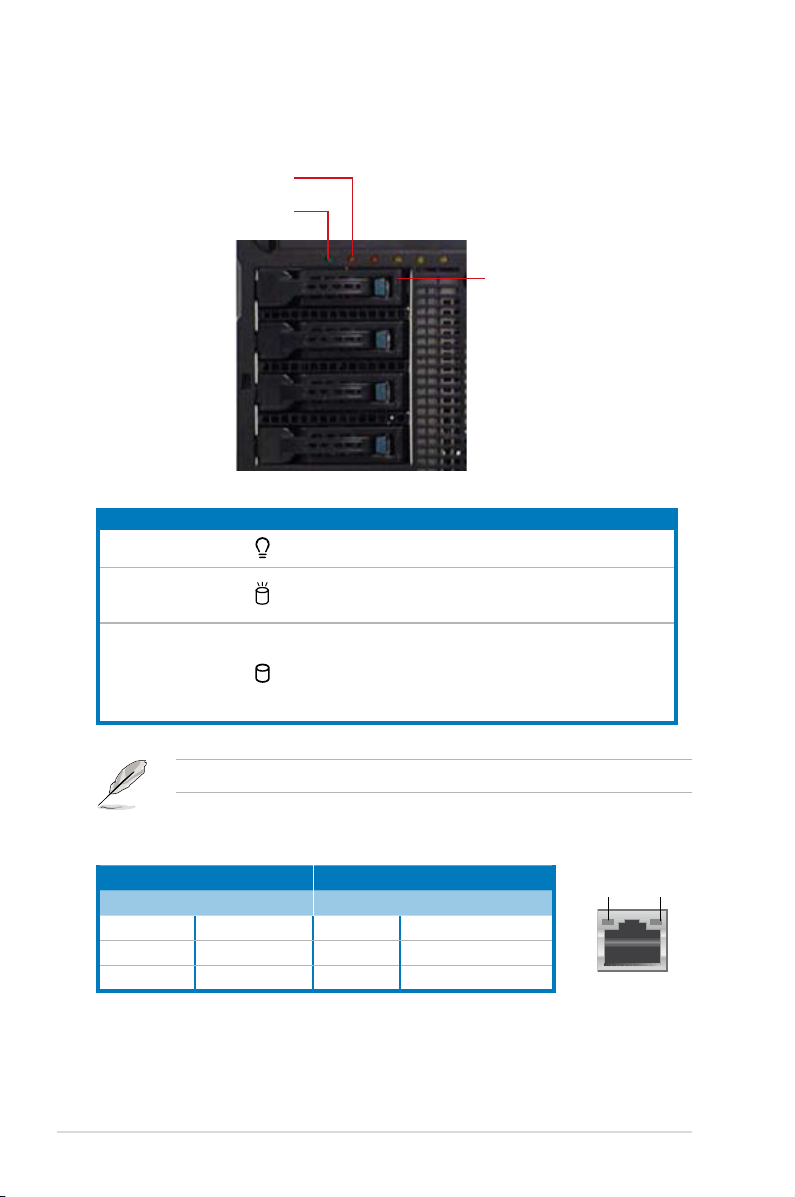
1.7.1 Front panel LEDs
HDD Access LED
Power LED
LED Icon Display status Description
Power LED ON System power ON
Drive Status LED
HDD Access LED
OFF
Blinking
Green
No activity
Read/write data into the HDD
Bridge board connected to backplane
Installed HDD is in good condition
Drive status LED
The Power and HDD Access LEDs are visible even if the system front bezel is closed.
Red
Green/Red blinking
HDD failure
HDD rebuilding using the RAID card
1.7.2 Rear panel LEDs
Activity Link LED Speed LED
Status Description Status Description
OFF No link OFF 10 Mbps connection
ORANGE Linked ORANGE 100 Mbps connection
BLINKING Data activity GREEN 1 Gbps connection
Chapter 1: Product introduction1-8
ACT/LINK
LED
LAN port
SPEED
LED
Page 21

Chapter 2
This chapter lists the hardware setup
procedures that you have to perform when
installing or removing system components.
ASUS ESC2000 G2
Hardware setup
Page 22

2.1 Chassis cover
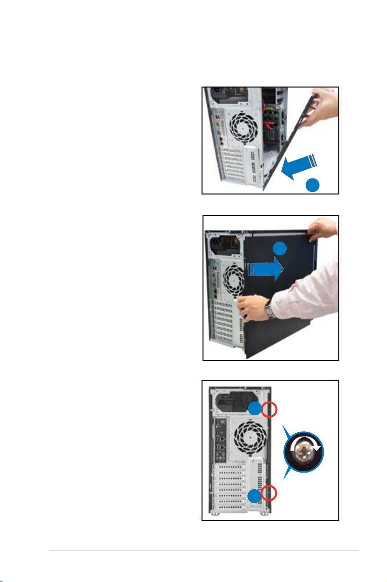
2.1.1 Removing the side cover
• Ensure that you unplug the power cord before removing the side cover.
• Take extra care when removing the side cover. Keep your ngers from components
inside the chassis that can cause injury, such as the CPU fan, rear fan, and other
sharp-edged parts.
• The images of the workstation shown in this section are for reference purpose only
and may not exactly match the model you purchase.
To remove the side cover:
1. Remove the two screws that secure the
left side cover of the chassis.
1
1
2. Slide the side cover for about half an inch
toward the rear until it disengaged from
the chassis. Carefully lift the side cover
and set it aside.
2
Chapter 2: Hardware setup2-2
Page 23
2.1.2 Reinstalling the side cover
To reinstall the side cover:
1. Match and insert the lower sliding edge
of the side cover to the chassis edge.
2. Position the side cover to the chassis.
3. Slide the side cover toward the front panel
until it snaps in place.
1
3
4. Drive in the two screws you removed
earlier to secure the side cover.
4
4
2-3ASUS ESC2000 G2
Page 24
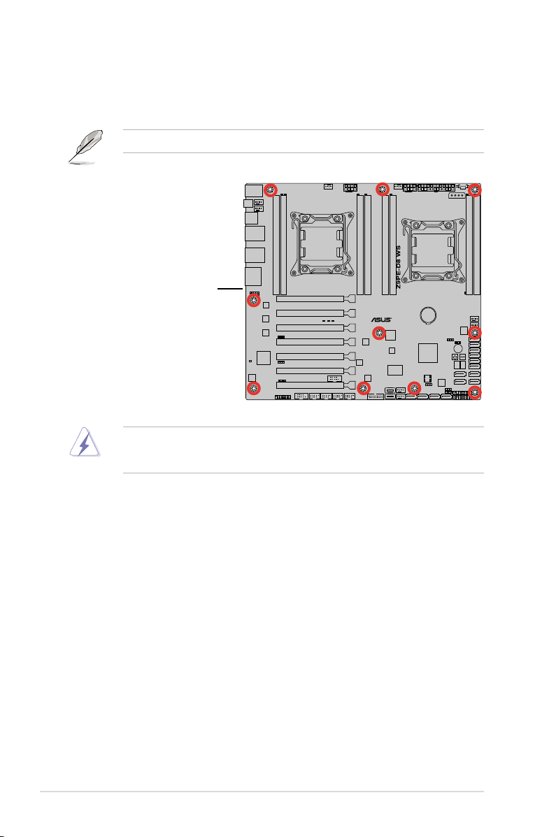
2.2 Motherboard overview
The barebone server comes with the Z9PE-D8 WS motherboard already installed. The
motherboard is secured to the chassis by ten (10) screws as indicated by the circles in the
illustration below.
Refer to
Chapter 3: Motherboard Information
Place this side towards
the rear of the chassis
Ensure to unplug the power cord before installing or removing any motherboard component
or connection. Failure to do so can cause you physical injury and damage the motherboard
components.
for detailed information on the motherboard.
Chapter 2: Hardware setup2-4
Page 25
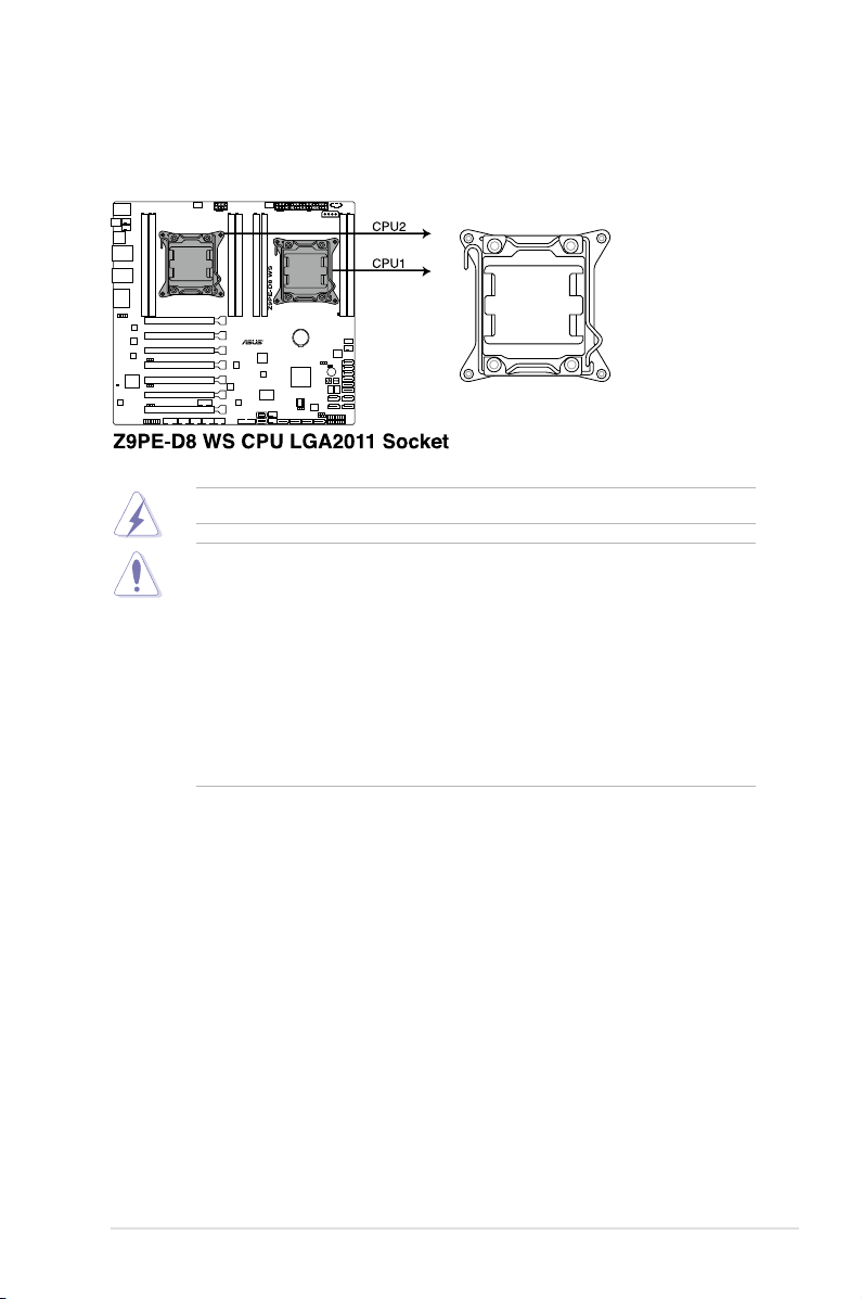
2.3 Central Processing Unit (CPU)
The motherboard comes with a surface mount LGA2011 socket designed for the Intel® Xeon®
E5-2600 series processors.
Ensure that all power cables are unplugged before installing the CPU.
• Upon purchase of the motherboard, ensure that the PnP cap is on the socket and
the socket contacts are not bent. Contact your retailer immediately if the PnP cap
is missing, or if you see any damage to the PnP cap/socket contacts/motherboard
components. ASUS shoulders the repair cost only if the damage is shipment/transit-
related.
• Keep the cap after installing the motherboard. ASUS will process Return Merchandise
Authorization (RMA) requests only if the motherboard comes with the cap on the
LGA2011 socket.
• The product warranty does not cover damage to the socket contacts resulting from
incorrect CPU installation/removal, or misplacement/loss/incorrect removal of the PnP
cap.
2-5ASUS ESC2000 G2
Page 26
B
A
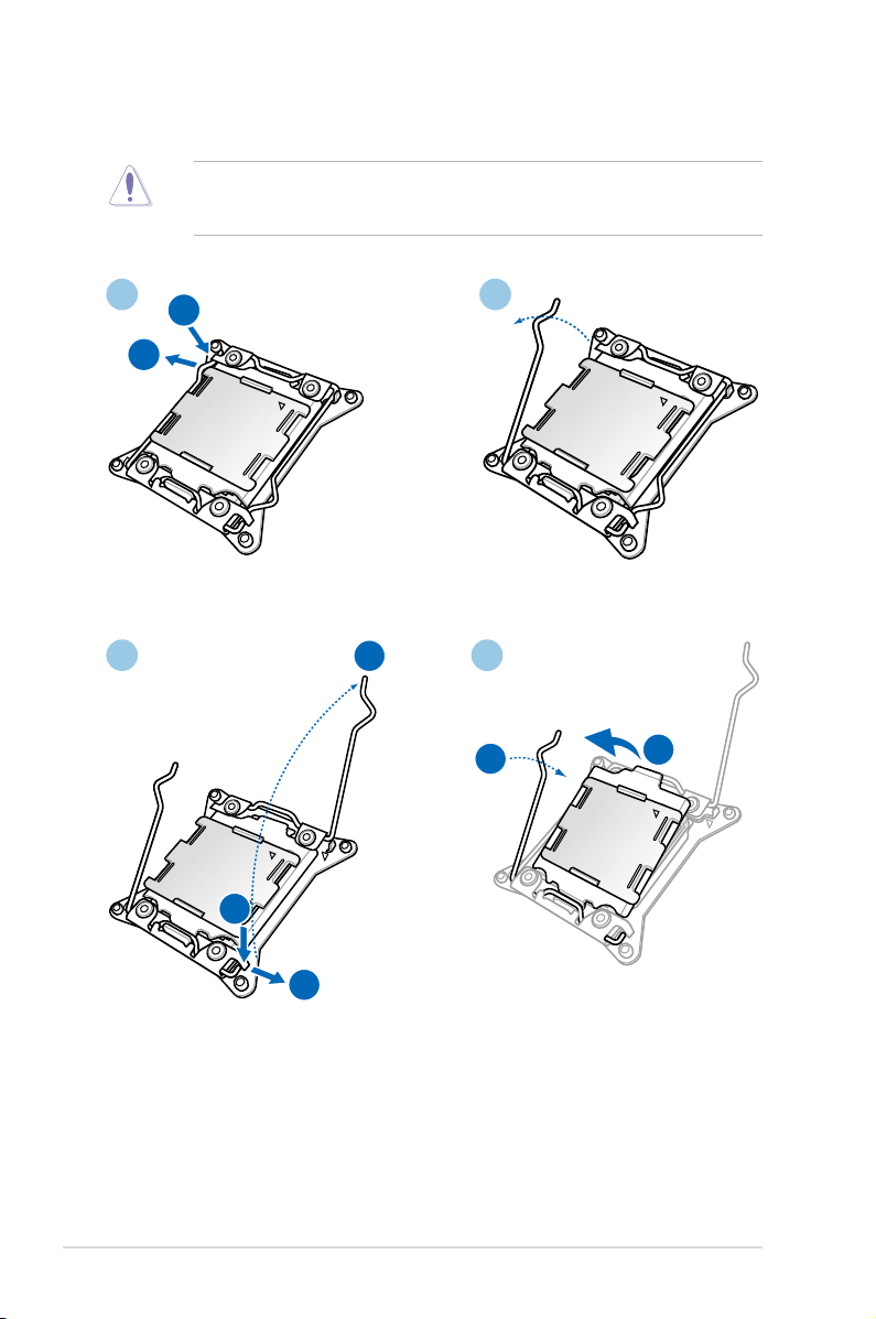
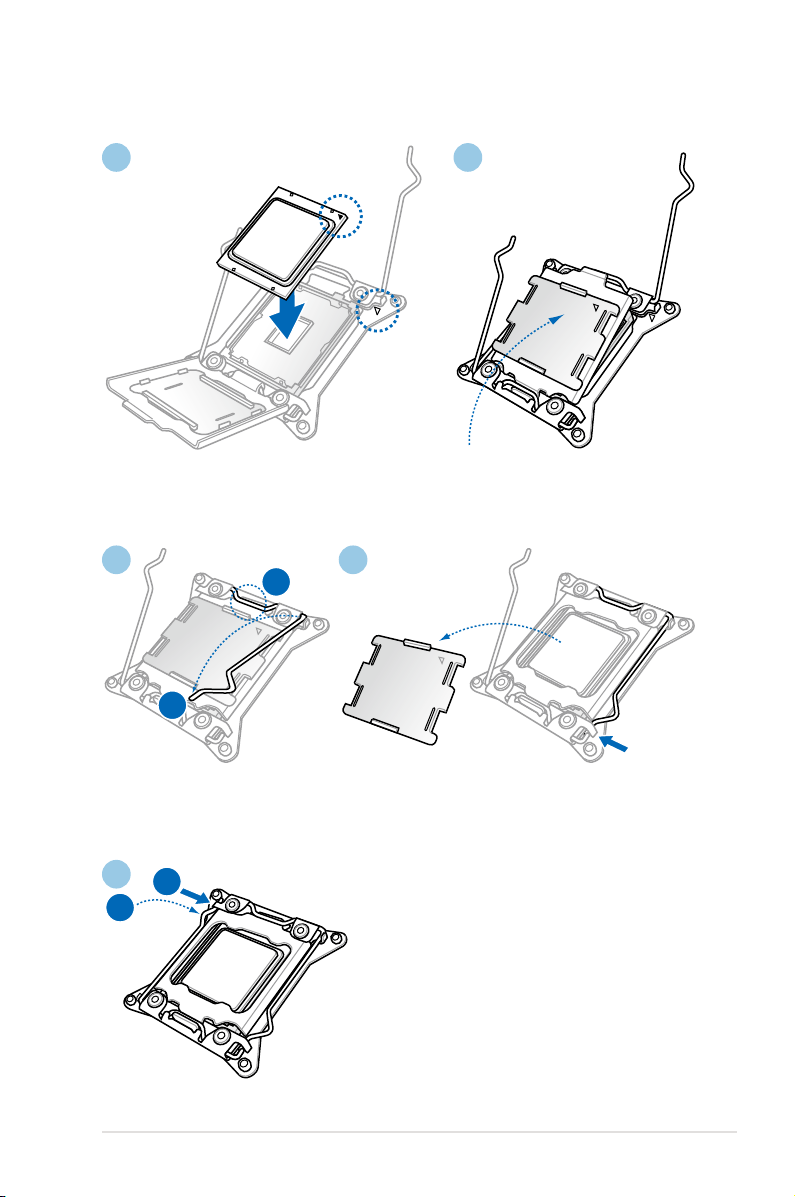
2.3.1 CPU installation
B
C
A
B
A
Please note the order in opening/ closing the double latch. Follow the instructions printed on
the metal sealing hatch or the illustrations shown below in this manual. The plastic cap will pop
up automatically once the CPU is in place and the hatch properly sealed down.
1 2
3 4
Chapter 2: Hardware setup2-6
Page 27
B
A
B
A
5 6
7 8
9
2-7ASUS ESC2000 G2
Page 28
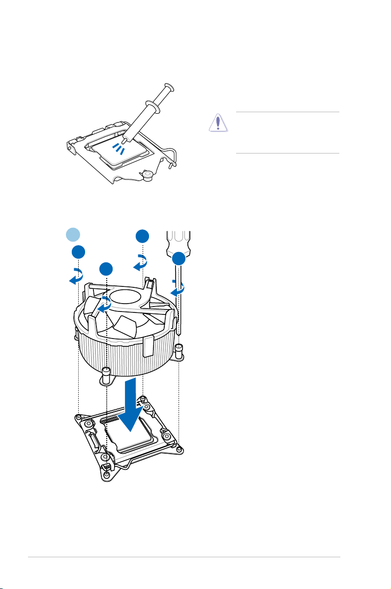
2.3.2 CPU heatsink and fan assembly installation
A
B
B
A
Apply the Thermal Interface Material
to the CPU heatsink and CPU before
you install the heatsink and fan if
necessary.
To install the CPU heatsink and fan assembly
1
Chapter 2: Hardware setup2-8
Page 29

2
DO NOT forget to connect the CPU_FAN connector! Hardware monitoring errors can occur
if you fail to plug this connector.
2-9ASUS ESC2000 G2
Page 30
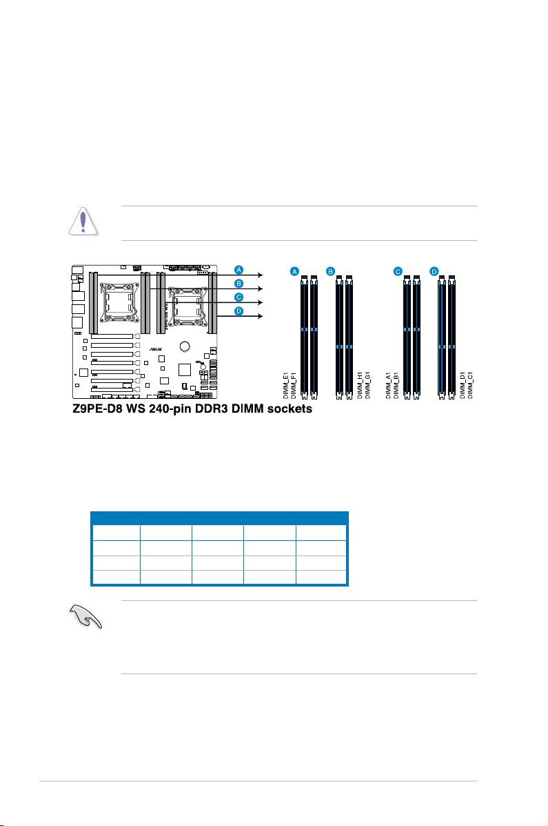
2.4 System memory
2.4.1 Overview
The motherboard comes with eight (four DIMM per CPU) Double Data Rate 3 (DDR3) Dual
Inline Memory Modules (DIMM) sockets.
A DDR3 module has the same physical dimensions as a DDR2 DIMM but is notched
differently to prevent installation on a DDR2 DIMM socket. DDR3 modules are developed for
better performance with less power consumption.
The gure illustrates the location of the DDR3 DIMM sockets:
A DDR3 module is notched differently from a DDR or DDR2 module. DO NOT install a DDR
or DDR2 memory module to the DDR3 slot.
2.4.2 MemoryCongurations
You may install 1GB, 2GB, 4GB, 8GB, 16GB and 32GB* RDIMMs or 1GB, 2GB, 4GB and
8GB* with ECC/Non-ECC UDIMMs or 8GB, 16GB and 32GB* LR-DIMMs into the DIMM
sockets using the memory congurations in this section.
1CPUConguration(mustonCPU1)
DIMM_A1 DIMM_B1 DIMM_C1 DIMM_D1
1 DIMMs
2 DIMMs
4 DIMMs
X
X X
X X X X
• *Refer to ASUS Server AVL for latest update.
• Install the DIMMs starting from slot A1 (CPU1) and E1 (CPU2).
• Always install DIMMs with the same CAS latency. For optimum compatibility, it is
recommended that you obtain memory modules from the same vendor.
Chapter 2: Hardware setup2-10
Page 31

2CPUConguration
DIMM_A1 DIMM_B1 DIMM_C1 DIMM_D1
1 DIMMs
2 DIMMs
4 DIMMs
8 DIMMs
X
X
X X
X X X X
2CPUConguration
DIMM_E1 DIMM_F1 DIMM_G1 DIMM_H1
1 DIMMs
2 DIMMs
4 DIMMs
8 DIMMs
X
X X
X X X X
2.4.3 Installing a DIMM
Ensure to unplug the power supply before adding or removing DIMMs or other system
components. Failure to do so may cause severe damage to both the motherboard and the
components.
1. Unlock a DIMM socket by pressing
the retaining clip outward.
2. Align a DIMM on the socket such that
the notch on the DIMM matches the
DIMM slot key on the socket.
A DIMM is keyed with a notch so that it ts in only one direction. DO NOT force a DIMM into
a socket in the wrong direction to avoid damaging the DIMM.
DIMM notch
DIMM slot key
1
2
Unlocked retaining clip
2-11ASUS ESC2000 G2
Page 32

3. Hold the DIMM by both of its ends,
then insert the DIMM vertically into
the socket. Apply force to both ends
of the DIMM simultaneously until the
retaining clip snaps back into place,
and the DIMM cannot be pushed in
any further to ensure proper sitting of
the DIMM.
Always insert the DIMM into the socket VERTICALLY to prevent DIMM notch damage.
2.4.4 Removing a DIMM
1. Press the retaining clip outward to
unlock the DIMM.
2. Remove the DIMM from the socket.
Support the DIMM lightly with your ngers when pressing the retaining clip. The DIMM
might get damaged when it ips out with extra force.
3
3
Locked Retaining Clip
2
1
Chapter 2: Hardware setup2-12
Page 33

2.5 Front panel assembly
Before you can install a 5.25-inch drive, you should rst remove the front panel assembly
(front bezel and front panel cover).
2.5.1 Removing the front panel assembly
To remove the front panel assembly:
1. Locate the three hooked tabs on the chassis side rail.
2. Shift the hooked tabs and take off the front bezel.
2.5.2 Reinstalling the front panel assembly
To reinstall the front panel assembly:
1. Hook the other side of the front panel
assembly to the chassis.
2. Swing the front panel assembly and
snap it back into place.
2-13ASUS ESC2000 G2
Page 34

2.6 5.25-inch drives
Ensure to unplug the power cable before installing or removing any system components.
Failure to do so may cause damage to the motherboard and other system components!
The system comes with three 5.25-inch drive
bays located on the upper front part of the
chassis. An optical drive that comes standard/
optional with the system package occupies
the uppermost bay (labeled 1). The lower bays
(labeled 2 and 3) are available for additional
5.25-inch optical, zip, or oppy disk drives.
You must remove the front panel
assembly before installing a 5.25-inch
drive.
Installing a 5.25-inch drive
1. Unscrew and remove the metal cover
of the bay where you want to install the
5.25-inch drive, and take off the plastic
cover on the front bezel at the same
position.
2. Insert the drive into the bay and slide
the bay lock to the right until it clicks in
place.
1
2
3
2
3. Connect the SATA cable to the SATA
connector on the back of the drive.
4. Connect a power plug from the power
supply to the power connector on the
back of the drive.
4
3
Chapter 2: Hardware setup2-14
Page 35

2.7 SATA hard disk drives
The hard disk drive module cage on the front panel, including externally removable trays for
mounting SATA hard disk drives, allows you to access the drive trays by simply opening the
front bezel.
An HDD module cage comes with a SATA backplane. Ensure of the type of HDD module
cage you purchase before buying hard disks.
2.7.1 Installing the HDD module cage
1. Examine the chassis and ensure the bay space is free of wires and other obstructions.
2. Level the HDD module cage latch
counterclockwise.
3. Insert the HDD module cage into the bay.
3
2
4. When the HDD module cage is
completed inserted, the cage latch will
be pushed back clockwise.
4
5. Lock the cage latch properly.
6. Connect the appropriate cables to the
SATA backplane on the HDD module
cage.
5
2-15ASUS ESC2000 G2
Page 36

2.7.2 Removing the HDD module cage
1. Disconnect the all cables from the SATA backplane on the HDD module cage.
2.
Level the HDD module cage latch
counterclockwise. The HDD module
cage will be pushed out of the chassis.
2
3. Completely pull out the HDD module
cage.
2.7.3 Installing a hot-swap SATA hard disk drive
1. Release a drive tray by pushing the
spring lock to the right, and then pulling
the tray lever outward. The drive tray
ejects slightly after you pull out the lever.
Chapter 2: Hardware setup2-16
Page 37

2. Firmly hold the tray lever and pull the
drive tray out of the bay.
3. Take note of the drive tray holes. Each
side has three holes to t different types
of hard disk drives. Use two screws on
each side to secure the hard disk drive.
4. Place a SATA hard disk drive on the tray,
and then secure it with four screws.
5. Carefully insert the drive tray and push
it all the way to the depth of the bay until
just a small fraction of the tray edge
protrudes.
When installed, the SATA connector on the drive connects to the SATA interface on the
backplane.
2-17ASUS ESC2000 G2
Page 38

6. Push the tray lever until it clicks, and
secures the drive tray in place. The drive
tray is correctly placed when its front
edge aligns with the bay edge.
7. Repeat steps 1 to 6 if you wish to install
a second SATA drive.
2.7.4 Removing and reinstalling the backplane
DO NOT remove the backplane unless necessary!
1. Remove all hot-swap HDD trays from the
chassis.
2. Disconnect all cables from the SATA
backplane.
3. Loosen the four screws on the
backplane.
4. Firmly hold the backplane, lift it up and
remove it from the module.
5. Follow the previous instructions in
reverse to reinstall the backplane.
Chapter 2: Hardware setup2-18
Page 39

2.8 Expansion cards
7
The system is designed with an expansion card lock on the rear panel for you to install or
remove an expansion card in less steps.
Ensure to unplug the power cord before installing or removing expansion cards. Failure to
do so may cause severe damage to the motherboard and other system components!
Slot
Slot Description
No.
1
PCI-E x16 (Gen3 x16/ x8 mode, auto-switch to x8 mode when slot 2 is occupied)
2
PCI-E x16 (Gen3 x8 mode)
3
PCI-E x16 (Gen3 x16/ x8 mode; auto-switch to x8 mode when slot 4 is occupied)
4
PCI-E x16 (Gen3 x8 mode)
5
PCI-E x16 (Gen3 x16 mode)
6
PCI-E x16 (Gen3 x8 mode)
7
PCI-E x16 (Gen3 x16 mode)
2-19ASUS ESC2000 G2
Page 40

2.8.1 Installing an expansion card
1. Before installing the expansion card, read the documentation that came with it and
make the necessary hardware settings for the card.
2. Lay the system on its side on a at, stable surface.
3. Push down the expansion card lock latch (step a) and lift up the expansion card lock
(step b), as shown in the right gure.
a
Expansion card lock latches
Expansion card locks
b
4. Remove the metal slot cover opposite
the slot where you wish to install an
expansion card.
5. Align the card golden ngers with the
slot, and then press rmly until the card is
completely seated on the slot.
Chapter 2: Hardware setup2-20
Page 41

6. Restore the expansion card lock to its
original position. A light click indicates
that the card is locked in place.
2.8.2 Conguringanexpansioncard
After installing the expansion card, congure the it by adjusting the software settings.
1. Turn on the system and change the necessary BIOS settings, if any. See Chapter 4 for
information on BIOS setup.
2. Install the software drivers for the expansion card.
IRQ assignments for this motherboard
A B C D E F G H
PCIEx16_1 shared – – – – – – –
PCIEx16_2 shared – – – – – – –
PCIEx16_3 shared – – – – – – –
PCIEx16_4 shared – – – – – – –
PCIEx16_5 shared – – – – – – –
PCIEx16_6 shared – – – – – – –
PCIEx16_7 shared – – – – – – –
Marvell9230 shared – – – – – – –
VIA1394 – – shared – – – – –
Asmedia USB3.0-1 – – shared – – – – –
Asmedia USB3.0-2 – – – shared – – – –
LAN1 (82574L) shared –
LAN2 (82574L)
SATA Controller 1 – – – shared – – – –
SATA Controller 2 – – – shared – – – –
USB 2.0 Controller 1 – – – – – – – shared
USB 2.0 Controller 2 – shared – – – – – –
HD Audio – – – – – – shared –
– shared – –
–
– – – –
– – – –
2-21ASUS ESC2000 G2
Page 42

2.9 Cable connections
• The bundled system cables are pre-connected before shipment. You do not need to
disconnect these cables unless you will remove pre-installed components to install
additional devices.
• Refer to Chapter 3 for detailed information on the connectors.
2.9.1 Motherboard connections
1
2
2
1
3
1
7
1
5
5
4
4
1
5
6
Standard cables connected to the motherboard
1. System fan connectors (from power supply to motherboard)
2. 8-pin 12V power connectors (from power supply to motherboard)
3. 24-pin ATX power connector (from system fan to motherboard)
4. Front panel USB connectors (from motherboard to front I/O board)
5. SATA connectors (from motherboard to SATA backplane)
6. System/Auxiliary panel connectors (from motherboard to front I/O board)
7. Front panel audio connector (from motherboard to front I/O board)
Chapter 2: Hardware setup2-22
Page 43

2.9.2 SATA backplane connections
An SATA backplane comes pre-installed in the ESC2000 G2. The SATA backplane has
four 22-pin SATA connectors to support Serial ATA hard disk drives. The backplane design
incorporates a hot swap feature to allow easy connection or removal of SATA hard disks. The
LEDs on the backplane connect to the front panel LEDs to indicate HDD status. See section
1.7 LED information for details.
Front side
The front side of the SATA backplane faces the front panel when installed. This side includes
four SATA connectors for the hot swap drive trays.
HDD1
HDD2
Drive status LEDs
HDD3
HDD4
Each SATA connector is labeled (HDD1, HDD2,
HDD3, HDD4) so you can easily determine their
counterpart connectors at the back side of the
backplane. Refer to the table for reference.
HDD Device Front side connector Back side connector
HDD 1 HDD1 CON1
HDD 2 HDD2 CON2
HDD 3 HDD3 CON3
HDD 4 HDD4 CON4
2-23ASUS ESC2000 G2
Page 44

Back side
The back side of the SATA backplane faces the rear panel when installed. This side includes
the power connectors and SATA interfaces for the motherboard Serial ATA connectors.
U1
CON1
CON2
CON4
CON3
Connectors Description
U1
CON1/CON2/
CON3/CON4
Connects to 4-pin plug of the power supply
Connects to SATA/SAS connectors on the motherboard
Chapter 2: Hardware setup2-24
Page 45

2.10 Removable components
You may need to remove previously installed system components when installing or removing
system devices, or when you need to replace defective components. This section tells how to
remove the front and rear system fans.
2.10.1 Removing rear system fan
To remove the rear system fan:
1. Unplug the system fan cable from
the
CHA_FAN1
motherboard.
2. Shift the two hooked tabs leftward and
rightward respectively.
connector on the
2-25ASUS ESC2000 G2
Page 46

3. Carefully take off the system fan.
4. Follow the previous instructions in
reverse to reinstall the rear system fan.
2.10.2 Removing front system fan
To remove the front system fan:
1. Remove the two screws that secure the
right side cover.
1
2. Locate the front system fan near the
5.25-inch drive bays.
3. Squeeze the front system fan latches
(step a) and pull out the front system
fan (step b), as shown in the right gure.
4. Follow the previous instructions in
reverse to reinstall the front system fan.
1
a
b
a
Chapter 2: Hardware setup2-26
Page 47

2.11 Installing the ASMB6 management board
Follow the steps below to install an optional ASMB management board on your motherboard.
1. Locate the ASMB6 header on the
motherboard.
2. Orient and press the ASMB6
management card in place
2-27ASUS ESC2000 G2
Page 48

Chapter 2: Hardware setup2-28
Page 49

Chapter 3
This chapter gives information about the
motherboard that comes with the workstation.
This chapter includes the motherboard layout,
jumper settings, and connector locations.
ASUS ESC2000 G2
Motherboard Info
Page 50

3.1 Motherboard layout
Refer to 3.5 Connectors for more information about rear panel connectors and internal
connectors.
Chapter 3: Motherboard information3-2
Page 51

Layout contents
Internal connectors Page
1. Hard disk activity LED connector (4-pin HDLED1) 3-21
2. USB connectors (10-1 pin USB78, USB910; A-type USB 12/11) 3-22
3. USB connectors (USB3_34) 3-22
4. CPU, front and rear fan connectors (4-pin CPU_FAN1-2,
FRNT_FAN1-4, REAR_FAN1-2)
5. Power supply SMBus Connector (PSUSMB1) 3-23
6. Serial port connectors (10-1 pin COM1/COM2) 3-23
7. Serial ATA 6.0/3.0 Gb/s connectors (7-pin SATA6G_1-2 [blue];
7-pin SATA3G_3-6 [black])
8. Marvell Serial ATA 6.0 Gb/s connectors (7-pin SATA6G_E1/E2/
E3/E4 [gray])
9. Serial ATA SCU connectors (7-pin SATA_SCU1-4 [black]) 3-19
10. EATX power connectors (24-pin EATXPWR1, 8-pin EATX12V1/
EATX12V2)
11. System panel connector (20-1 pin PANEL1) 3-24
12. Auxiliary panel connector (20-2 pin AUX_PANEL1) 3-25
13. Digital audio connector (4-1 pin SPDIF_OUT) 3-26
14. IEEE 1394a port connectors (10-1 pin IE1394_1/2) 3-26
15. VGA connector (VGA_HDR1) 3-27
16. Front panel audio connector (10-1 pin AAFP) 3-27
17. ASMB6 header (ASMB6) 3-28
3-21
3-19
3-18
3-20
Jumpers Page
1. Clear RTC RAM (CLRTC1) 3-5
2. VGA Controller setting (DIAG_VIEW1) 3-6
3. SMBUS connection setting (TESLA_M_SW) 3-6
4. LSI MegaRAID or Intel RSTe selection jumper (3-pin RAID_
SEL1)
5. ME rmware force recovery setting (3-pin ME_RCVR1) 3-7
ASUS ESC2000 G2 3-3
3-7
Page 52

Onboard LEDs Page
1. Standby power LEDs 3-9
2. DIMM Error LED (ERR_DIMM) 3-9
3. Baseboard Management Controller LED (BMC_LED1) 3-10
4. Q-Code LED (LED1_LED2) 3-11
Slots/Socket Page
1. CPU sockets 2-5
2. DDR3 sockets 2-10
3. PCI Express x8 / PCI Express x16 slots 2-19
Onboard Buttons/switches Page
1. Power on button 3-8
2. Reset button 3-8
Chapter 3: Motherboard information3-4
Page 53

3.2 Jumpers
1. Clear RTC RAM (CLRTC1)
This jumper allows you to clear the Real Time Clock (RTC) RAM in CMOS. You can
clear the CMOS memory of date, time, and system setup parameters by erasing
the CMOS RTC RAM data. The onboard button cell battery powers the RAM data in
CMOS, which include system setup information such as system passwords.
To erase the RTC RAM:
1. Turn OFF the computer and unplug the power cord.
2. Move the jumper cap from pins 1-2 (default) to pins 2-3. Keep the cap on pins 2-3
for about 5–10 seconds, then move the cap back to pins 1-2.
3. Plug the power cord and turn ON the computer.
4. Hold down the <Del> key during the boot process and enter BIOS setup to re-
enter data.
Except when clearing the RTC RAM, never remove the cap on CLRTC jumper default
position. Removing the cap will cause system boot failure!
• If the steps above do not help, remove the onboard battery and move the jumper
again to clear the CMOS RTC RAM data. After the CMOS clearance, reinstall the
battery.
• You do not need to clear the RTC when the system hangs due to overclocking. For
system failure due to overclocking, use the C.P.R. (CPU Parameter Recall) feature.
Shut down and reboot the system so the BIOS can automatically reset parameter
settings to default values.
• Due to the chipset behavior, AC power off is required to enable C.P.R. function. You
must turn off and on the power supply or unplug and plug the power cord before
rebooting the system.
ASUS ESC2000 G2 3-5
Page 54

2. VGA controller setting (DIAG_VIEW1)
This jumper allows you to enable o disable the onboard VGA controller. Set to pins 1-2
to activate the VGA feature.
3. SMBUS connection setting (TESLA_M_SW)
This jumper allows you to select the connection to BMC or PHC for PCIE 1/3/5/7
SMBUS.
Chapter 3: Motherboard information3-6
Page 55

4. LSIMegaRAIDorIntelRSTeselectionjumper(3-pinRAID_SEL1)
This jumper allows you to select the PCH SATA RAID mode to use LSI MegaRAID
software or Intel® Rapid Storage Technology enterprise 3.0 RAID. Place the jumper
caps over pins 1–2 if you want to use the LSI MegaRAID software RAID Utility
(default); otherwise, place the jumper caps to pins 2–3 to use the Intel
®
Rapid Storage
Technology Enterprise Option ROM Utility.
5. MErmwareforcerecoverysetting(3-pinME_RCVR1)
This jumper allows you to force Intel Management Engine (ME) boot from recovery mode
when ME become corrupted.
ASUS ESC2000 G2 3-7
Page 56

3.3 Onboard buttons and switches
Z9PE-D8 Power on button
Z9PE-D8 WS Reset button
Onboard buttons and switches allow you to ne-tune performance when working on a bare or
open-case system. This is ideal for overclockers and gamers who continually change settings
to enhance system performance.
1. Power-on button
The motherboard comes with a power-on button that allows you to power up or wake
up the system. The button also lights up when the system is plugged to a power source
indicating that you should shut down the system and unplug the power cable before
removing or plugging in any motherboard component. The illustration below shows the
location of the onboard power-on button.
2. Reset button
Press the reset button to reboot the system.
Chapter 3: Motherboard information3-8
Page 57

3.4 Onboard LEDs
Z9PE-D8 WS Onboard LED
1. Standby Power LEDs
The motherboard comes with a standby power LED that lights up to indicate that the
system is ON, in sleep mode, or in soft-off mode. This is a reminder that you should
shut down the system and unplug the power cable before removing or plugging in any
motherboard component. The illustration below shows the location of the onboard LED.
The Standby Power LEDs will light up once the system is connected to a power source
2. DIMM Error LED (ERR_DIMM)
These LEDs light up to indicate an error in its nearby DIMM.
Enabled only with ASMB6-i KVM on-board.
ASUS ESC2000 G2 3-9
Page 58

3. Baseboard Management Controller LED (BMC_LED1)
The BMC LED works with the ASUS ASMB6 management device and indicates its
initiation status. When the PSU is plugged and the system is OFF, ASUS ASMB6
management device starts system initiation for about one (1) minute. The BMC LED
blinks after system initiation nishes.
Chapter 3: Motherboard information3-10
Page 59

4. Q-Code LEDs
The Q-Code LED design provides you the 2-digit display, allowing you to know the
system status. Refer to the Q-Code table below for details.
Q-Code table
Code Description
00
01
02
03
04
06
07
08
09
0A
0B
0C – 0D
0E
0F
10
11 – 14
15 – 18
19 – 1C
2B – 2F
30
Not used
Power on. Reset type detection (soft/hard).
AP initialization before microcode loading
System Agent initialization before microcode loading
PCH initialization before microcode loading
Microcode loading
AP initialization after microcode loading
System Agent initialization after microcode loading
PCH initialization after microcode loading
Initialization after microcode loading
Cache initialization
Reserved for future AMI SEC error codes
Microcode not found
Microcode not loaded
PEI Core is started
Pre-memory CPU initialization is started
Pre-memory System Agent initialization is started
Pre-memory PCH initialization is started
Memory initialization
Reserved for ASL (see ASL Status Codes section below)
ASUS ESC2000 G2 3-11
Page 60

Q-Code table (continued)
Code Description
31
32 – 36
37 – 3A
3B – 3E
4F
50 – 53
54
55
56
57
58
59
5A
5B
5C – 5F
E0
E1
E2
E3
E4 – E7
E8
E9
EA
EB
EC – EF
F0
F1
F2
F3
F4
F5 – F7
F8
F9
FA
FB – FF
60
61
62
Memory Installed
CPU post-memory initialization
Post-Memory System Agent initialization is started
Post-Memory PCH initialization is started
DXE IPL is started
Memory initialization error. Invalid memory type or incompatible memory
speed
Unspecied memory initialization error
Memory not installed
Invalid CPU type or Speed
CPU mismatch
CPU self test failed or possible CPU cache error
CPU micro-code is not found or micro-code update is failed
Internal CPU error
Reset PPI is not available
Reserved for future AMI error codes
S3 Resume is stared (S3 Resume PPI is called by the DXE IPL)
S3 Boot Script execution
Video repost
OS S3 wake vector call
Reserved for future AMI progress codes
S3 Resume Failed
S3 Resume PPI not Found
S3 Resume Boot Script Error
S3 OS Wake Error
Reserved for future AMI error codes
Recovery condition triggered by rmware (Auto recovery)
Recovery condition triggered by user (Forced recovery)
Recovery process started
Recovery rmware image is found
Recovery rmware image is loaded
Reserved for future AMI progress codes
Recovery PPI is not available
Recovery capsule is not found
Invalid recovery capsule
Reserved for future AMI error codes
DXE Core is started
NVRAM initialization
Installation of the PCH Runtime Services
Chapter 3: Motherboard information3-12
Page 61

Q-Code table (continued)
Code Description
AC
AD
AE
AF
B0
B1
B2
B3
B4
B5
B6
B7
B8– BF
D0
D1
D2
D3
D4
D5
D6
D7
D8
D9
DA
DB
DC
ACPI/ASL Checkpoints
Reserved for ASL (see ASL Status Codes section below)
Ready To Boot event
Legacy Boot event
Exit Boot Services event
Runtime Set Virtual Address MAP Begin
Runtime Set Virtual Address MAP End
Legacy Option ROM Initialization
System Reset
USB hot plug
PCI bus hot plug
Clean-up of NVRAM
Conguration Reset (reset of NVRAM settings)
Reserved for future AMI codes
CPU initialization error
System Agent initialization error
PCH initialization error
Some of the Architectural Protocols are not available
PCI resource allocation error. Out of Resources
No Space for Legacy Option ROM
No Console Output Devices are found
No Console Input Devices are found
Invalid password
Error loading Boot Option (LoadImage returned error)
Boot Option is failed (StartImage returned error)
Flash update is failed
Reset protocol is not available
Code Description
0x01
0x02
0x03
0x04
0x05
0x10
0x20
0x30
0x40
0xAC
0xAA
ASUS ESC2000 G2 3-13
System is entering S1 sleep state
System is entering S2 sleep state
System is entering S3 sleep state
System is entering S4 sleep state
System is entering S5 sleep state
System is waking up from the S1 sleep state
System is waking up from the S2 sleep state
System is waking up from the S3 sleep state
System is waking up from the S4 sleep state
System has transitioned into ACPI mode. Interrupt controller is in PIC mode.
System has transitioned into ACPI mode. Interrupt controller is in APIC mode.
Page 62

3.5 Connectors
3.5.1 Rear panel connectors
Rear panel connectors
1. PS/2 keyboard/mouse combo port 6. USB 2.0 ports 3 and 4
2. LAN (RJ-45) port 2* 7. USB 2.0 ports 1 and 2
3. LAN (RJ-45) port 1* 8. USB 3.0 ports 1 and 2
4. USB 2.0 ports 5 and 6 9. Audio I/O ports**
5. Optical S/PDIF out port
*and**:RefertothetablesonthenextpageforLANportandaudioportdenitions.
• Due to USB 3.0 controller limitation, USB 3.0 devices can only be used under
Windows® OS environment and after the USB 3.0 driver installation.
• USB 3.0 devices can only be used as data storage only.
• We strongly recommend that you connect USB 3.0 devices to USB 3.0 ports for faster
and better performance for your USB 3.0 devices.
Chapter 3: Motherboard information3-14
Page 63

* LAN port LED indications
Activity Link LED Speed LED
Status Description Status Description
OFF No link OFF 10 Mbps connection
ORANGE Linked ORANGE 100 Mbps connection
BLINKING Data activity GREEN 1 Gbps connection
ACT/LINK
LED
LAN port
SPEED
LED
**Audio2,4,6,or8-channelconguration
Port Headset
2-channel
Light Blue Line In Line In Line In Line In
Lime Line Out Front Speaker Out Front Speaker Out Front Speaker Out
Pink Mic In Mic In Mic In Mic In
Orange – – Center/Subwoofer Center/Subwoofer
Black – Rear Speaker Out Rear Speaker Out Rear Speaker Out
Gray – – – Side Speaker Out
4-channel 6-channel 8-channel
3.5.2 Audio I/O connections
Audio I/O ports
Connect to Headphone and Mic
ASUS ESC2000 G2 3-15
Page 64

Connect to Stereo Speakers
Connect to 2.1 channel Speakers
Connect to 4.1 channel Speakers
Chapter 3: Motherboard information3-16
Page 65

Connect to 5.1 channel Speakers
Connect to 7.1 channel Speakers
ASUS ESC2000 G2 3-17
Page 66

3.5.4 Internal connectors
1. Marvell® Serial ATA 6.0 Gb/s connectors (7-pin SATA6G_E1/E2/E3/E4 [gray])
These connectors connect to Serial ATA 6.0 Gb/s hard disk drives via Serial ATA 6.0
Gb/s signal cables.
• For high performance of ASUS SSD Caching, please connect one HDD and one SSD
to Marvell® SATA6G_E1/E2/E3/E4 connectors.
• For SSD Caching setup, you can use more than one SSD and only one HDD.
• You cannot use ASUS SSD Caching and Marvell
• For regular usage, the SATA6G_E1/E2/E3/E4 connectors are recommended for data
drivers.
•
You must install Windows® XP Service Pack 3 or later versions before using Serial ATA
hard disk drives.
• Press <Ctrl> + <M> during POST to enter the Marvell
a RAID conguration.
• If you want to install a Windows operating system to a RAID conguration created
using the Marvell® SATA controller, you have to create a RAID driver disk using the
motherboard support DVD and load the driver during OS installation. For 32/64bit
Windows XP OS, load rst the
®
92xx SATA Controller Dri
Marvell® shared library
ver. For Windows Vista / Windows 7 OS, load only the
Marvell® 92xx SATA Controller Driver
®
RAID at the same time.
.
®
RAID utility to create or delete
driver, and then load
Marvell
Chapter 3: Motherboard information3-18
Page 67

2. Serial ATA 6.0/3.0 Gb/s connectors (7-pin SATA6G_1-2 [blue]; 7-pin SATA3G_3-6
[black])
These connectors connect to Serial ATA 6.0Gb/s or 3.0 Gb/s hard disk drives and
optical disc drives via Serial ATA 6.0Gb/s or 3.0 Gb/s signal cables.
3. Serial ATA SCU connectors (7-pin SATA_SCU1-4 [black])
These connectors connect to Serial ATA 3.0 Gb/s hard disk drives and optical disc
drives via Serial ATA 3.0 Gb/s signal cables.
ASUS ESC2000 G2 3-19
Page 68

4. EATX power connectors (24-pin EATXPWR1, 8-pin EATX12V1/EATX12V2)
These connectors are for an EATX power supply plugs. The power supply plugs are
designed to t these connectors in only one orientation. Find the proper orientation and
push down rmly until the connectors completely t.
• DO NOT forget to connect the 24+8+8-pin power plugs; otherwise, the system will not
boot up.
• Use of a PSU with a higher power output is recommended when conguring a system
with more power-consuming devices. The system may become unstable or may not
boot up if the power is inadequate.
• This motherboard supports EATX2.0 PSU or later version.
• Ensure that your power supply unit (PSU) can provide at least the minimum power
required by your system.
Chapter 3: Motherboard information3-20
Page 69

5. CPU, front and rear fan connectors (4-pin CPU_FAN1-2, FRNT_FAN1–4,
REAR_FAN1-2)
The fan connectors support cooling fans. Connect the fan cables to the fan connectors
on the motherboard, ensuring that the black wire of each cable matches the ground pin
of the connector.
• DO NOT forget to connect the fan cables to the fan connectors. Insufcient air ow
inside the system may damage the motherboard components.
• These are not jumpers! DO NOT place jumper caps on the fan connectors!
• All fans feature the ASUS Fan Speed Control technology.
6. Hard disk activity LED connector (4-pin HDLED1)
This LED connector is for the storage add-on card cable connected to the SATA or SAS
add-on card. The read or write activities of any device connected to the SATA or SAS
add-on card causes the front panel LED to light up.
ASUS ESC2000 G2 3-21
Page 70

7. USB connectors (10-1 pin USB78, USB910; A-Type USB12/11)
These connectors are for USB 2.0 ports. Connect the USB module cables to
connectors USB78 and USB910, then install the modules to a slot opening at the back
of the system chassis. These USB connectors comply with USB 2.0 specication that
supports up to 480 Mbps connection speed.
8. USB connectors (USB3_34)
This connector is for USB 3.0 ports. Connect the USB module cable to connector
USB3_34.
Chapter 3: Motherboard information3-22
Page 71

9. Power supply SMBus Connector (PSUSMB1)
This connector supplies power for low-speed system management communications.
10. Serial port connectors (10-1 pin COM1/COM2)
These connectors are for the serial (COM) ports. Connect the serial port module cable
to one of these connectors, then install the module to a slot opening at the back of the
system chassis.
ASUS ESC2000 G2 3-23
Page 72

11. System panel connector (20-1 pin PANEL1)
This connector supports several chassis-mounted functions.
(1) System power LED (3-pin PLED)
This 3-pin connector is for the system power LED. Connect the chassis power
LED cable to this connector. The system power LED lights up when you turn on
the system power, and blinks when the system is in sleep mode.
(2) System warning speaker (4-pin SPEAKER)
This 4-pin connector is for the chassis-mounted system warning speaker. The
speaker allows you to hear system beeps and warnings.
(3) Hard disk drive activity LED (2-pin HDDLED)
This 2-pin connector is for the HDD Activity LED. Connect the HDD Activity LED
cable to this connector. The HDD LED lights up or ashes when data is read from
or written to the HDD.
(4) Power button/soft-off button (2-pin PWRSW)
This connector is for the system power button. Pressing the power button turns
the system on or puts the system in sleep or soft-off mode depending on the
BIOS settings. Pressing the power switch for more than four seconds while the
system is ON turns the system OFF.
(5) Reset button (2-pin RESET)
This 2-pin connector is for the chassis-mounted reset button for system reboot
without turning off the system power.
Chapter 3: Motherboard information3-24
Page 73

12. Auxiliary panel connector (20-2 pin AUX_PANEL1)
This connector is for additional front panel features including front panel SMB, locator
LED and switch, chassis intrusion, and LAN LEDs.
(1) Front panel SMB (6-1 pin FPSMB)
These leads connect the front panel SMBus cable.
(2) LAN activity LED (2-pin LAN12_LED
These leads are for Gigabit LAN activity LEDs on the front panel.
(3) Chassis intrusion (4-1 pin CHASSIS)
These leads are for the intrusion detection feature for chassis with intrusion
sensor or microswitch. When you remove any chassis component, the sensor
triggers and sends a high-level signal to these leads to record a chassis intrusion
event. The default setting is short CASEOPEN and GND pin by jumper cap to
disable the function.
(4) Locator LED (2-pin LOCATORLED1 and 2-pin LOCATORLED2)
These leads are for the locator LED1 and LED2 on the front panel. Connect the
Locator LED cables to these 2-pin connector. The LEDs will light up when the
Locator button is pressed.
(5) Locator Button/Swich (2-pin LOCATORBTN)
These leads are for the locator button on the front panel. This button queries the
state of the system locator.
)
ASUS ESC2000 G2 3-25
Page 74

13. Digital audio connector (4-1 pin SPDIF_OUT)
This connector is for an additional Sony/Philips Digital Interface (S/PDIF) port(s).
Connect the S/PDIF Out module cable to this connector, then install the module to a
slot opening at the back of the system chassis.
The S/PDIF module is purchased separately.
14. IEEE 1394a port connectors (10-1 pin IE1394_1/2)
These connectors are for IEEE 1394a port. Connect the IEEE 1394a module cable
to this connector, then install the module to a slot opening at the back of the system
chassis.
Never connect a USB cable to the IEEE 1394a connector. Doing so will damage the
motherboard!
The IEEE 1394a module is purchased separately.
Chapter 3: Motherboard information3-26
Page 75

15. VGA connector (VGA_HDR1)
This connector supports the VGA High Dynamic-Range interface.
16. Front panel audio connector (10-1 pin AAFP)
This connector is for a chassis-mounted front panel audio I/O module that supports
either HD Audio or legacy AC`97 audio standard. Connect one end of the front panel
audio I/O module cable to this connector.
• We recommend that you connect a high-denition front panel audio module to this
connector to avail of the motherboard’s high-denition audio capability.
• If you want to connect a high-denition front panel audio module to this connector, set
the Front Panel Type item in the BIOS setup to [HD]; if you want to connect an AC'97
front panel audio module to this connector, set the item to [AC97]. By default, this
connector is set to [HD].
ASUS ESC2000 G2 3-27
Page 76

17. ASMB6 header (ASMB6)
This connector supports the ASUS Server Management Board 6 series.
Chapter 3: Motherboard information3-28
Page 77

Chapter 4
This chapter tells how to change the system
settings through the BIOS Setup menus.
Detailed descriptions of the BIOS parameters
are also provided.
ASUS ESC2000 G2
BIOS setup
Page 78

4.1 Managing and updating your BIOS
The following utilities allow you to manage and update the motherboard Basic Input/Output
System (BIOS) setup:
1.
ASUS CrashFree BIOS 3
when the BIOS le fails or gets corrupted.)
2.
ASUS EZ Flash 2
3.
BUPDATER utility
drive.)
Refer to the corresponding sections for details on these utilities.
Save a copy of the original motherboard BIOS le to a bootable
in case you need to restore the BIOS in the future. Copy the original motherboard BIOS
using the BUPDATER utility.
(To recover the BIOS using a bootable USB ash disk drive
(Updates the BIOS using a USB ash disk.)
(Updates the BIOS in DOS mode using a bootable USB ash disk
USB ash disk drive
4.1.1 ASUS CrashFree BIOS 3 utility
The ASUS CrashFree BIOS 3 is an auto recovery tool that allows you to restore the BIOS le
when it fails or gets corrupted during the updating process. You can update a corrupted BIOS
le using a USB ash drive that contains the updated BIOS le.
Prepare a USB ash drive containing the updated motherboard BIOS before using this
utility.
RecoveringtheBIOSfromaUSBashdrive
To recover the BIOS from a USB ash drive:
1. Insert the USB ash drive with the original or updated BIOS le to one USB port on the
system.
2. The utility will automatically recover the BIOS. It resets the system when the BIOS
recovery nished.
DO NOT shut down or reset the system while recovering the BIOS! Doing so would cause
system boot failure!
The recovered BIOS may not be the latest BIOS version for this motherboard. Visit the
ASUS website at www.asus.com to download the latest BIOS le.
4-2 Chapter 4: BIOS setup
Page 79

4.1.2 ASUS EZ Flash 2 Utility
The ASUS EZ Flash 2 Utility feature allows you to update the BIOS without having to use a
DOS-based utility.
Before you start using this utility, download the latest BIOS from the ASUS website at www.
asus.com.
To update the BIOS using EZ Flash 2 Utility
1. Insert the USB ash disk that contains the latest BIOS le to the USB port.
2. Enter the BIOS setup program. Go to the
and press <Enter> to enable it.
ASUSTek EZ Flash 2 Utility V01.04
Flash Info
MODEL: Z9PE-D8 WS VER: 0405 DATE: 03/19/2012
File Path:\
Drive Info Folder Info
fs0:\ 12/09/10 10:23p 4194304 Z9PE-D8 WS.ROM
File Info
MODEL: VER: DATE:
Help Info
menu to select
Tool
ASUS EZ Flash 2 Utility
Exit
[Enter] Select or Load [Tab] Switch [Up/Down/PageUp/PageDown/Home/End] Move [Esc] Exit [F2] Backup
3. Press <Tab> to switch to the Drive Info eld.
4. Press the Up/Down arrow keys to nd the USB ash disk that contains the latest BIOS,
and then press <Enter>.
5. Press <Tab> to switch to the
Folder Info eld.
6. Press the Up/Down arrow keys to nd the BIOS le, and then press <Enter> to perform
the BIOS update process. Reboot the system when the update process is done.
ASUS ESC2000 G2 4-3
Page 80

• This function can support devices such as a USB ash disk with FAT 32/16 format and
single partition only.
• DO NOT shut down or reset the system while updating the BIOS to prevent system
boot failure!
Ensure to load the BIOS default settings to ensure system compatibility and stability. Press
<F5> and select Yes to load the BIOS default settings.
4.1.3 BUPDATER utility
The succeeding BIOS screens are for reference only. The actual BIOS screen displays may
not be the same as shown.
The BUPDATER utility allows you to update the BIOS le in DOS environment using a
bootable USB ash disk drive with the updated BIOS le.
UpdatingtheBIOSle
To update the BIOS le using the BUPDATER utility:
1. Visit the ASUS website at www.asus.com and download the latest BIOS le for the
motherboard. Save the BIOS le to a bootable USB ash disk drive.
2. Copy the BUPDATER utility (BUPDATER.exe) from the ASUS support website at
support.asus.com to the bootable USB ash disk drive you created earlier.
3. Boot the system in DOS mode, then at the prompt, type:
BUPDATER /i[lename].ROM
where [lename] is the latest or the original BIOS le on the bootable USB ash disk
drive, then press <Enter>.
A:\>BUPDATER /i[le name].ROM
4-4 Chapter 4: BIOS setup
Page 81

The utility veries the le, then starts updating the BIOS le.
ASUSTek BIOS Update for DOS V1.06 (03/19/2012)
FLASH TYPE: MXIC 25L1605A
Current ROM
BOARD: Z9PE-D8 WS
VER: 0405
DATE: 03/19/2012
PATH:
WARNING! Do not turn off power during ash BIOS
Note
Writing BIOS:
Update ROM
BOARD: Z9PE-D8 WS
VER: 0405
DATE: 03/19/2012
DO NOT shut down or reset the system while updating the BIOS to prevent system boot
failure!
5. The utility returns to the DOS prompt after the BIOS update process is completed.
Reboot the system from the hard disk drive.
The BIOS update is nished! Please restart your system.
C:\>
ASUS ESC2000 G2 4-5
Page 82

4.2 BIOS setup program
This motherboard supports a programmable rmware chip that you can update using the
provided utility described in section
4.1 Managing and updating your BIOS
Use the BIOS Setup program when you are installing a motherboard, reconguring your
system, or prompted to “Run Setup.” This section explains how to congure your system
using this utility.
Even if you are not prompted to use the Setup program, you can change the conguration of
your computer in the future. For example, you can enable the security password feature or
change the power management settings. This requires you to recongure your system using
the BIOS Setup program so that the computer can recognize these changes and record them
in the CMOS RAM of the rmware chip.
The rmware chip on the motherboard stores the Setup utility. When you start up the
computer, the system provides you with the opportunity to run this program. Press <Del>
during the Power-On Self-Test (POST) to enter the Setup utility; otherwise, POST continues
with its test routines.
If you wish to enter Setup after POST, restart the system by pressing <Ctrl+Alt+Delete>, or by
pressing the reset button on the system chassis. You can also restart by turning the system
off and then back on. Do this last option only if the rst two failed.
The Setup program is designed to make it as easy to use as possible. Being a menu-driven
program, it lets you scroll through the various sub-menus and make your selections from the
available options using the navigation keys.
• The default BIOS settings for this motherboard apply for most conditions to ensure
optimum performance. If the system becomes unstable after changing any BIOS
settings, load the default settings to ensure system compatibility and stability. Press
<F5> and select
• The BIOS setup screens shown in this section are for reference purposes only, and
may not exactly match what you see on your screen.
• Visit the ASUS website (www.asus.com) to download the latest BIOS le for this
motherboard.
to load the BIOS default settings.
Yes
.
4-6 Chapter 4: BIOS setup
Page 83

4.2.1 BIOS menu screen
Menu bar CongurationeldsMenu items
Aptio Setup Utility - Copyright (C) 2011 American Megatrends, Inc.
Main Ai Tweaker Server Mgmt Advanced Event Logs Boot Monitor Security Tool Exit
BIOS Information
BIOS Vendor American Megatrends
Core Version 4.6.4.1
Compliancy UEFI 2.1; PI 0.9
BIOS Version 0208 x64
Build Date 03/19/2012
System Date [Thu 03/29/2012]
System Time [18:23:29]
Access Level Administrator
Memory Information
Total Memory 16384 MB (DDR3)
Processor
CPU Speed 2200 MHz
Count: 2
Version 2.14.1219. Copyright (C) 2011 American Megatrends, Inc.
Set the Date, Use Tab to
switch between Data elements.
→←: Select Screen
↑↓: Select Item
Enter: Select Item
+/-: Change Opt.
F1: General Help
F2: Previous Values
F5: Optimized Defaults
F10: Save & Exit
ESC: Exit
General help
Navigation keys
4.2.2 Menu bar
The menu bar on top of the screen has the following main items:
For changing the basic system conguration
Main
Ai Tweaker
Server Mgmt
Advanced
Event Logs
Monitor
Security
Boot
Tool
Exit
For changing the advanced system settings
For changing the event log settings
For displaying the system temperature, power status, and changing
For changing the security settings
For changing the system boot conguration
For conguring options for special functions
For selecting the exit options
To select an item on the menu bar, press the right or left arrow key on the keyboard until the
desired item is highlighted.
For changing the Ai Tweaker settings
For changing the server management settings
the fan settings
ASUS ESC2000 G2 4-7
Page 84

4.2.3 Menu items
The highlighted item on the menu bar displays the specic items for that menu. For example,
selecting
The other items (Event Logs, Advanced, Monitor, Boot, Tool, and Exit) on the menu bar have
their respective menu items.
shows the Main menu items.
Main
4.2.4 Submenu items
A solid triangle before each item on any menu screen means that the item has a submenu. To
display the submenu, select the item and press <Enter>.
4.2.5 Navigation keys
At the bottom right corner of a menu screen are the navigation keys for the BIOS setup
program. Use the navigation keys to select items in the menu and change the settings.
4.2.6 General help
At the top right corner of the menu screen is a brief description of the selected item.
4.2.7 Congurationelds
These elds show the values for the menu items. If an item is user-congurable, you can
change the value of the eld opposite the item. You cannot select an item that is not usercongurable.
A congurable eld is enclosed in brackets, and is highlighted when selected. To change the
value of a eld, select it and press <Enter> to display a list of options.
4.2.8 Pop-up window
Select a menu item and press <Enter> to display a pop-up window with the conguration
options for that item.
4.2.9 Scroll bar
A scroll bar appears on the right side of a menu screen when there are items that do not t on
the screen. Press the Up/Down arrow keys or <Page Up> /<Page Down> keys to display the
other items on the screen.
4-8 Chapter 4: BIOS setup
Page 85

4.3 Main menu
When you enter the BIOS Setup program, the Main menu screen appears. The Main menu
provides you an overview of the basic system information, and allows you to set the system
date, time, language, and security settings.
The Server Management tab and menu appear only when you install the ASMB card on the
motherboard.
Aptio Setup Utility - Copyright (C) 2011 American Megatrends, Inc.
Main Ai Tweaker Advanced Server Mgmt Event Logs Boot Monitor Security Tool Exit
BIOS Information
BIOS Vendor American Megatrends
Core Version 4.6.4.1
Compliancy UEFI 2.1; PI 0.9
BIOS Version 0208 x64
Build Date 03/19/2012
System Date [Thu 03/29/2012]
System Time [15:07:28]
Access Level Administrator
Memory Information
Total Memory 16384 MB (DDR3)
Processor
CPU Speed 2200 MHz
Count: 2
Version 2.14.1219. Copyright (C) 2011 American Megatrends, Inc.
Set the Date, Use Tab to
switch between Data elements.
→←: Select Screen
↑↓: Select Item
Enter: Select Item
+/-: Change Opt.
F1: General Help
F2: Previous Values
F5: Optimized Defaults
F10: Save & Exit
ESC: Exit
4.3.1 System Date [Day xx/xx/xxxx]
Allows you to set the system date.
4.3.2 System Time [xx:xx:xx]
Allows you to set the system time.
ASUS ESC2000 G2 4-9
Page 86

4.4 Ai Tweaker menu
The Ai Tweaker menu items allow you to congure overclocking-related items.
Be cautious when changing the settings of the Ai Tweaker menu items. Incorrect eld
values can cause the system to malfunction.
The conguration options for this section vary depending on the CPU and DIMM model you
installed on the motherboard.
Aptio Setup Utility - Copyright (C) 2011 American Megatrends, Inc.
Main Ai Tweaker Advanced Server Mgmt Event Logs Boot Monitor Security Tool Exit
Target CPU Turbo-Mode Speed : 2500MHz
Ai Overclock Tuner [Auto]
CPU Ratio [Auto]
DRAM Timing Control
CPU1 Voltage [Auto]
VCORE_CPU1 +0.930 V
CPU1 VSA Voltage [Auto]
VSA_CPU1 +0.896 V
CPU2 Voltage [Auto]
VCORE_CPU2 +0.928 V
CPU2 VSA Voltage [Auto]
VSA_CPU2 +0.884 V
DRAM Voltage (CHA, CHB) [Auto]
+VDDQ_AB_CPU1 +1.474 V
DRAM Voltage (CHC, CHD) [Auto]
+VDDQ_CD_CPU1 +1.476 V
DRAM Voltage (CHE, CHF) [Auto]
+VDDQ_EF_CPU2 +1.474 V
DRAM Voltage (CHG, CHH) [Auto]
+VDDQ_GH_CPU2 +1.476 V
Clock Spread Spectrum [Disabled]
Min=0.800V
Max=1.520V
Standard=By CPU
Increment=0.005V
=/-:Raise/Reduce
: Select Screen
→←
: Select Item
↑↓
Enter: Select Item
+/-: Change Opt.
F1: General Help
F2: Previous Values
F5: Optimized Defaults
F10: Save & Exit
ESC: Exit
Version 2.14.1219. Copyright (C) 2011 American Megatrends, Inc.
Ai Overclock Tuner [Auto]
Allows you to select the CPU overclocking options to achieve the desired CPU internal
frequency. Select any of these preset overclocking conguration options:
[Auto] Loads the optimal settings for the system.
[Manual] Allows you to individually set overclocking parameters.
BCLK Frequency [XXX]
Allows you to adjust the CPU and VGA frequency to enhance the system performance.
Set
Ai Overclock Tuner
keys to adjust the value. You can also key in the desired value using the numeric
keypad. The values range from 80.0MHz to 300.0MHz.
4-10 Chapter 4: BIOS setup
to [Manual] to show BCLK Frequency. Use the <+> and <->
Page 87

CPU Ratio [Auto]
This item allows users adjust the maximum non-turbo CPU ratio. Use the <+> and <-> keys to
adjust the value. The values range from 12 to 57 with 1 interval.
CPU1 Voltage [Auto]
Use the <+> and <-> keys to adjust the value. The values range from 0.800V to 1.520V with
0.005V interval.
CPU1 VSA Voltage [Auto]
Use the <+> and <-> keys to adjust the value. The values range from 0.800V to 1.520V with
0.005V interval.
CPU2 Voltage [Auto]
Use the <+> and <-> keys to adjust the value. The values range from 0.800V to 1.520V with
0.005V interval.
CPU2 VSA Voltage [Auto]
Use the <+> and <-> keys to adjust the value. The values range from 0.800V to 1.520V with
0.005V interval.
DRAM Voltage (CHA, CHB) [Auto]
Use the <+> and <-> keys to adjust the value. The values range from 1.20V to 1.90V with
0.005V interval.
DRAM Voltage (CHC, CHD) [Auto]
Use the <+> and <-> keys to adjust the value. The values range from 1.20V to 1.90V with
0.005V interval.
DRAM Voltage (CHE, CHF) [Auto]
Use the <+> and <-> keys to adjust the value. The values range from 1.20V to 1.90V with
0.005V interval.
DRAM Voltage (CHG, CHH) [Auto]
Use the <+> and <-> keys to adjust the value. The values range from 1.20V to 1.90V with
0.005V interval.
Clock Spread Spectrum [Disabled]
[Disabled] Enhances BCLK overclocking ability.
[Enabled] For [EMI] control.
ASUS ESC2000 G2 4-11
Page 88

4.4.1 DRAM Timing Control
Aptio Setup Utility - Copyright (C) 2011 American Megatrends, Inc.
Main Ai Tweaker Advanced Server Mgmt Event Logs Boot Monitor Security Tool Exit
Primary Timings
DRAM CAS# Latency [Auto]
DRAM CAS# Latency 9
DRAM RAS# to CAS# Delay [Auto]
DRAM RAS# to CAS# Delay 9
DRAM RAS# PRE Time [Auto]
DRAM RAS# PRE Time 9
DRAM RAS# ACT Time [Auto]
DRAM RAS# ACT Time 24
DRAM COMMAND Mode [Auto]
DRAM COMMAND Mode 1
Secondary Timings
DRAM RAS# to RAS# Delay [Auto]
DRAM RAS# to RAS# Delay 4
DRAM REF Cycle Time [Auto]
DRAM REF Cycle Time 74
DRAM WRITE Recovery Time [Auto]
DRAM WRITE Recovery Time 10
DRAM READ to PRE Time [Auto]
DRAM READ to PRE Time 5
DRAM FOUR ACT WIN Time [Auto]
DRAM FOUR ACT WIN Time 20
DRAM WRITE to READ Delay [Auto]
DRAM WRITE to READ Delay 5
DRAM Write Latency [Auto]
DRAM Write Latency 7
Version 2.14.1219. Copyright (C) 2011 American Megatrends, Inc.
Min=0.800V
Max=1.520V
Standard=By CPU
Increment=0.005V
=/-:Raise/Reduce
→←: Select Screen
↑↓: Select Item
Enter: Select Item
+/-: Change Opt.
F1: General Help
F2: Previous Values
F5: Optimized Defaults
F10: Save & Exit
ESC: Exit
Use the scroll to view items.
Primary Timings
DRAM CAS# Latency [Auto]
Use the <+> and <-> keys to adjust the value. The values range from 3 to 15 with 1
interval.
DRAM RAS# to CAS# Delay [Auto]
Use the <+> and <-> keys to adjust the value. The values range from 4 to 15 with 1
interval.
DRAM RAS# PRE Time [Auto]
Use the <+> and <-> keys to adjust the value. The values range from 4 to 15 with 1
interval.
DRAM RAS# ACT Time [Auto]
Use the <+> and <-> keys to adjust the value. The values range from 4 to 40 with 1
interval.
4-12 Chapter 4: BIOS setup
Page 89

DRAM COMMAND Mode [Auto]
Use the <+> and <-> keys to adjust the value. The values range from 1 to 3 with 1
interval.
Secondary Timings
DRAM RAS# to RAS# Delay [Auto]
Use the <+> and <-> keys to adjust the value. The values range from 4 to 7 with 1
interval.
DRAM REF Cycle Time [Auto]
Use the <+> and <-> keys to adjust the value. The values range from 48 to 255 with 1
interval.
DRAM WRITE Recovery Time [Auto]
Use the <+> and <-> keys to adjust the value. The values range from 5 to 31 with 1
interval.
DRAM READ to PRE Time [Auto]
Use the <+> and <-> keys to adjust the value. The values range from 4 to 15 with 1
interval.
DRAM FOUR ACT WIN Time [Auto]
Use the <+> and <-> keys to adjust the value. The values range from 16 to 63 with 1
interval.
DRAM WRITE to READ Delay [Auto]
Use the <+> and <-> keys to adjust the value. The values range from 4 to 15 with 1
interval.
DRAM WRITE Latency [Auto]
Use the <+> and <-> keys to adjust the value. The values range from 1 to 15 with 1
interval.
ASUS ESC2000 G2 4-13
Page 90

4.5 Advanced menu
The Advanced menu items allow you to change the settings for the CPU and other system
devices.
Take caution when changing the settings of the Advanced menu items. Incorrect eld
values can cause the system to malfunction.
Aptio Setup Utility - Copyright (C) 2011 American Megatrends, Inc.
Main Ai Tweaker Advanced Server Mgmt Event Logs Boot Monitor Security Tool Exit
CPU Conguration
CPU Power Management Conguration
Chipset Conguration
PCH SATA Conguration
PCH SCU SAS Conguration
PCI Subsystem Settings
USB Conguration
ACPI Settings
WHEA Conguration
APM
Serial Port Console Redirection
Onboard LAN Conguration
Marvell SATA Conguration
Onboard Devices Conguration
Runtime Error Logging
Version 2.14.1219. Copyright (C) 2011 American Megatrends, Inc.
4.5.1 CPUConguration
Aptio Setup Utility - Copyright (C) 2011 American Megatrends, Inc.
Advanced
CPU Confguration
CPU Conguration Parameters
→←: Select Screen
↑↓: Select Item
Enter: Select Item
+/-: Change Opt.
F1: General Help
F2: Previous Values
F5: Optimized Defaults
F10: Save & Exit
ESC: Exit
Socket specic CPU Information
Socket 1 CPU Information
Socket 2 CPU Information
CPU Speed 2200 MHz
64-bit Supported
Hyper Threading [Enabled]
Active Processor Cores [All]
Limit CPUID Maximum [Disabled]
Execute Disable Bit [Enabled]
Server Class [Custom]
Hardware Prefetcher [Enabled]
Adjacent Cache Line Prefetch [Enabled]
DCU Streamer Prefetcher [Enabled]
DCU IP Pretetcher [Enabled]
Intel Virtualization Technology [Enabled]
Local APIC Mode [Auto]
Version 2.14.1219. Copyright (C) 2011 American Megatrends, Inc.
→←: Select Screen
↑↓: Select Item
Enter: Select Item
+/-: Change Opt.
F1: General Help
F2: Previous Values
F5: Optimized Defaults
F10: Save & Exit
ESC: Exit
4-14 Chapter 4: BIOS setup
Page 91

Socket 1 CPU Information
Enter to view socket specic CPU Information.
Aptio Setup Utility - Copyright (C) 2011 American Megatrends, Inc.
Advanced
Socket 1 CPU Information
Intel(R) Xeon(R) CPU E5-2660 0 @ 2.20GHz
CPU Signature 206d6
Microcode Patch 613
Max CPU Speed 2200 MHz
Min CPU Speed 1200 MHz
Processor Cores 6
Intel HT Technology Supported
Intel VT-X Technology Supported
L1 Data Cache 32 kB x 8
L1 Code Cache 32 kB x 8
L2 Cache 256 kB x 8
L3 Cache 20480 kB
Version 2.14.1219. Copyright (C) 2011 American Megatrends, Inc.
Socket 2 CPU Information
Enter to view socket specic CPU Information.
Aptio Setup Utility - Copyright (C) 2011 American Megatrends, Inc.
Advanced
Socket 2 CPU Information
Intel(R) Xeon(R) CPU E5-2660 0 @ 2.20GHz
CPU Signature 206d6
Microcode Patch 613
Max CPU Speed 2200 MHz
Min CPU Speed 1200 MHz
Processor Cores 8
Intel HT Technology Supported
Intel VT-X Technology Supported
L1 Data Cache 32 kB x 8
L1 Code Cache 32 kB x 8
L2 Cache 256 kB x 8
L3 Cache 20480 kB
→←: Select Screen
↑↓: Select Item
Enter: Select Item
+/-: Change Opt.
F1: General Help
F2: Previous Values
F5: Optimized Defaults
F10: Save & Exit
ESC: Exit
: Select Screen
→←
: Select Item
↑↓
Enter: Select Item
+/-: Change Opt.
F1: General Help
F2: Previous Values
F5: Optimized Defaults
F10: Save & Exit
ESC: Exit
Version 2.14.1219. Copyright (C) 2011 American Megatrends, Inc.
ASUS ESC2000 G2 4-15
Page 92

Hyper Threading [Enabled]
This item allows you to enable/disable the Intel Hyper-Threading Technology function. Enable
for Windows XP and Linux or disable for other OS. When disabled, only one thread per
activated core is enabled.
Conguration options: [Disabled] [Enabled]
Active Processor Cores [All]
This item sets the number of cores to enable in each processor package.
Conguration options: [All] [1] [2] [3] [4] [5] [6] [7]
Limit CPUID Maximum [Disabled]
Setting this item to [Enabled] allows legacy operating system to boot even without support for
CPUs with extended CPUID functions.
Conguration options: [Disabled] [Enabled]
Execute Disable Bit [Enabled]
XP can prevent certain classes of malicious buffer overow attacks when combined with
a supporting OS (Windows Server 2003 SP1, Windows XP SP2, SuSE Linux 9.2, Redhat
Enterprise 3 Update 3).
Conguration options: [Disabled] [Enabled]
Server Class [Custom]
Use Intel recommended prefetch settings.
Conguration options: [Enterprise] [High Performance(HPC)] [Custom]
You can only customize the items below when you enable the Server Class to
[Custom]
.
Hardware Prefetcher [Enabled]
This item allows you to turn on/off the mid level cache(L2) streamer prefetcher.
Conguration options: [Disabled] [Enabled]
Adjacent Cache Line Prefetch [Enabled]
This item allows you to turn on/off prefetching of adjacent cache lines.
Conguration options: [Disabled] [Enabled]
DCU Streamer Prefetcher [Enabled]
This item allows you to enable/disable prefetching of next L1 data line based upon
multiple loads in same cache line.
Conguration options: [Disabled] [Enabled]
DCU IP Prefetcher [Enabled]
This item allows you to enable/disable prefetching of next L1 line based upon
sequential load history.
Conguration options: [Disabled] [Enabled]
4-16 Chapter 4: BIOS setup
Page 93

Intel Virtualization Technology [Enabled]
When this item is enabled, VMM can utilize the additional hardware capabilities provided by
Vanderpool Technology.
Conguration options: [Disabled] [Enabled]
Local APIC Mode [Auto]
Allows you to enable one or both the Advanced Programmable Interrupt Controllers (APIC)
with APIC ID values greater than 254.
Conguration options: [Auto] [xAPIC] []x2APIC]
4.5.2 CPUPowerManagementConguration
Aptio Setup Utility - Copyright (C) 2011 American Megatrends, Inc.
Advanced
CPU Power Management Confguration
Power Technology [Custom]
Enhanced Intel SpeedStep Technolog [Enabled]
Turbo Mode [Enabled]
P-STATE Coordination [HW_ALL]
CPU C3 Report [Disabled]
CPU C6 Report [Enabled]
CPU C7 Report [Disabled]
Package C State limit [C6]
Energy Performance [Balanced Performance]
Factory long duration power limit 95 Watts
Long Duration Power Limit 0
Factory long duration maintained 1000 ms
Long Duration Maintained 0
Recommended short duration power1 1.2 * Long Duration
Short Duration Power Limit 0
Version 2.14.1219. Copyright (C) 2011 American Megatrends, Inc.
Enable the power
management features
→←: Select Screen
↑↓: Select Item
Enter: Select Item
+/-: Change Opt.
F1: General Help
F2: Previous Values
F5: Optimized Defaults
F10: Save & Exit
ESC: Exit
Power Technology [Custom]
This item allows you to enable power management features.
Conguration options: [Disable] [Energy Efcient] [Custom]
You can only customize the items below when you enable the Power Technology to
.
[Custom]
Enhanced Intel SpeedStep Technology [Enabled]
Enable Intel SpeedStep for allowing the system operation system to dynamically
adjust processor voltage and cores frequency to result in decreased average power
consumption and decreased average heat production.
Conguration options: [Disabled] [Enabled]
ASUS ESC2000 G2 4-17
Page 94

Turbo Mode [Enabled]
This item automatically allows processor cores to run faster than the base operating
frequency if it’s operating below power, current, and temperature specication limit.
Conguration options: [Disabled] [Enabled]
P-STATE Coordination [HW_ALL]
This item allows you to change P-STATE Coordination type.
Conguration options: [HW_ALL] [SW_ALL] [SW_ANY]
CPU C3 Report [Disabled]
This item allows you to enable/disable CPU C3(ACPI C2) report.
Conguration options: [Disabled] [Enabled]
CPU C6 Report [Enabled]
This item allows you to enable/disable CPU C6(ACPI C3) report.
Conguration options: [Disabled] [Enabled]
Power Technology [Custom]
This item allows you to enable power management features.
Conguration options: [Disable] [Energy Efcient] [Custom]
Enhanced Intel SpeedStep Technology [Enabled]
Enable Intel SpeedStep for allowing the system operation system to dynamically
adjust processor voltage and cores frequency to result in decreased average power
consumption and decreased average heat production.
Conguration options: [Disabled] [Enabled]
Turbo Mode [Enabled]
This item automatically allows processor cores to run faster than the base operating
frequency if it’s operating below power, current, and temperature specication limit.
Conguration options: [Disabled] [Enabled]
P-STATE Coordination [HW_ALL]
This item allows you to change P-STATE Coordination type.
Conguration options: [HW_ALL] [SW_ALL] [SW_ANY]
CPU C3 Report [Disabled]
This item allows you to enable/disable CPU C3(ACPI C2) report.
Conguration options: [Disabled] [Enabled]
CPU C6 Report [Enabled]
This item allows you to enable/disable CPU C6(ACPI C3) report.
Conguration options: [Disabled] [Enabled]
4-18 Chapter 4: BIOS setup
Page 95

CPU C7 Report [Disabled]
This item allows you to enable/disable CPU C7(ACPI C3) report.
Conguration options: [Disabled] [Enabled]
Package C State limit [C6]
This item allows you to set package C State limit.
Conguration options: [C0] [C2] [C6] [C7] [No Limit]
Energy Performance [Balanced Performance]
This item allows you to optimize between performance and power savings.
Conguration options: [Performance] [Balanced Performance] [Balanced Energy] [Energy
Efcient]
Factory long duration power limit 95Watts
Long Duration Power Limit 0
Allows you to set long duration power limit in watts. Use the <+> and <-> keys to adjust the
value.
Factory long duration maintained 1000 ms
Long Duration Maintained 0
Allows you to set time window which the long duration power is maintained. Use the <+> and
<-> keys to adjust the value.
Recommended short duration power1 1.2 * Long Duration
Short Duration Power Limit 0
Allows you to set short duration power limit in watts. Use the <+> and <-> keys to adjust the
value.
ASUS ESC2000 G2 4-19
Page 96

4.5.3 ChipsetConguration
Aptio Setup Utility - Copyright (C) 2011 American Megatrends, Inc.
Advanced
QPI Conguration
Memory Conguration
CPU II0 Bridge Conguration
PCH Conguration
Intel(R) VT for Directed I/O Conguration
QPI Conguration Page
QPIConguration
Aptio Setup Utility - Copyright (C) 2011 American Megatrends, Inc.
Advanced
Current QPI Link Speed Fast
Current QPI Link Freq 7.2 GT/s
Isoc [Enabled]
QPI Link Speed Mode [Fast]
QPI Link Frequency Select [Auto]
QPI Link0s [Disabled]
QPI Link0p [Disabled]
QPI Link1 [Enabled]
Isoc [Enabled]
Conguration options: [Disabled] [Enabled]
QPI Link Speed Mode [Fast]
This item allows you to select the QPI link speed as either the fast mode or slow mode.
Conguration options: [Slow] [Fast]
QPI Link Frequency Select [Auto]
This item allows for selecting the QPI link frequency
Conguration options: [Auto] [6.4 GT/s] [7.2 GT/s (Fast Mode Only)] [8.0 GT/s (Fast
Mode Only)]
QPI Link0s [Disabled]
Conguration options: [Disabled] [Enabled]
QPI Link0p [Disabled]
Conguration options: [Disabled] [Enabled]
QPI Link1 [Enabled]
Conguration options: [Disabled] [Enabled]
Enable/Disable Isoc
4-20 Chapter 4: BIOS setup
Page 97

MemoryConguration
Aptio Setup Utility - Copyright (C) 2011 American Megatrends, Inc.
Advanced
Compatibility RID [Enabled]
Memory Conguration
Total Memory 16384 MB (DDR3)
Current Memory Mode Independent
Currently Memory Speed 1333 MHz
Mirroring Not Possible
Sparing Not Possible
Memory Mode [Independent]
Numa [Enabled]
DDR Speed [Auto]
Channel Interleaving [Auto]
Rank Interleaving [Auto]
Patrol Scrub [Disabled]
Demand Scrub [Enabled]
Data Scrambling [Enabled]
Device Tagging [Disabled]
Thermal Throttling [CLTT]
Enable High Temp. [Disabled]
Allow 2x Refresh [Enabled]
Altitude [300 M]
Memory HOT sensor support [Enabled]
DIMM Information
Version 2.14.1219. Copyright (C) 2011 American Megatrends, Inc.
Compatibility RID [Enabled]
Supports compatibility revision ID (CRID) functionality mentioned in Sandybridge BIOS
spec.
Conguration options: [Enabled] [Disabled]
Memory Mode [Independent]
Select the mode for memory initializaton.
Conguration options: [Independent]
Numa [Enalbled]
Allows you to disable or enable Non Uniform Memory Access.
Conguration options: [Enabled] [Disabled]
DDR Speed [Auto]
This item allows you to congure force DDR speed.
Conguration options: [Auto] [Force DDR3 800] [Force DDR3 1066] [Force DDR3
1333] [Force DDR3 1600] [Force DDR3 1866] [Force DDR3 2133] [Force DDR3 2400]
[Force DDR3 2666]
Channel Interleaving [Auto]
Select different channel interleaving setting.
Conguration options: [Auto] [1 Way] [2 Way] [3 Way] [4 Way]
Support for Compatibility
Revision ID(CRID)
Functionality mentioned in
Sandybridge bios spec
→←: Select Screen
↑↓: Select Item
Enter: Select Item
+/-: Change Opt.
F1: General Help
F2: Previous Values
F5: Optimized Defaults
F10: Save & Exit
ESC: Exit
ASUS ESC2000 G2 4-21
Page 98

Rank Interleaving [Auto]
Select different rank interleaving setting.
Conguration options: [Auto] [1 Way] [2 Way] [4 Way] [8 Way]
Patrol Scrub [Disabled]
This item allows you to enable/disable Patrol Scrub.
Conguration options: [Disabled] [Enabled]
Demand Scrub [Enabled]
This item allows you to enable/disable Demand Scrubbing Feature.
Conguration options: [Enabled] [Disabled]
Data Scrambling [Enabled]
This item allows you to enable/disable Data Scrambling.
Conguration options: [Enabled] [Disabled]
Device Tagging [Disabled]
This item allows you to enable/disable Device Tagging.
Conguration options: [Enabled] [Disabled]
Thermal Throttling [CLTT]
Conguration options: [Disabled] [OLTT] [CLTT]
Enable High Temp. [Disabled]
This item allows you to enable/disable high temperature mode.
Conguration options: [Disabled] [Enabled]
Allow 2x Refresh [Enabled]
This item allows you to enable/disable refreshing function.
Conguration options: [Disabled] [Enabled]
Altitude [300 M]
Shows system altitude above the sea level in meters.
Conguration options: [Auto] [300 M] [900 M] [1500 M] [3000 M]
Memory Hot sensor support [Enabled]
Conguration options: [Disabled] [Enabled]
4-22 Chapter 4: BIOS setup
Page 99

DIMM Information
Aptio Setup Utility - Copyright (C) 2011 American Megatrends, Inc.
Advanced
CPU1 DIMM Information
DIMM_A1 Present 8192 MB(Indep
DIMM_B1 Not Present
DIMM_C1 Not Present
DIMM_D1 Not Present
CPU2 DIMM Information
DIMM_E1 Not Present
DIMM_F1 Not Present
DIMM_G1 Present 8192 MB Inde[
DIMM_H1 Not Present
CPUIIOBridgeConguration
Aptio Setup Utility - Copyright (C) 2011 American Megatrends, Inc.
Advanced
Intel(R) I/OAT [Disabled]
DCA Support [Enabled]
VGA Priority [Offboard]
TargetVGA VGA From CPU
Version 2.14.1219. Copyright (C) 2011 American Megatrends, Inc.
Intel(R) I/OAT [Disabled]
This item allows you to enable/disable Intel I/O accelaration technology.
Conguration options: [Disabled] [Enabled]
DCA Support [Enabled]
This item allows you to enable/disable direct cache access support.
Conguration options: [Disabled] [Enabled]
ASUS ESC2000 G2 4-23
Page 100

VGA Priority [offboard]
This item allows you to decide the priority between onboard and 1st offboard video
device found.
Conguration options: [Onboard] [Offboard]
PCHConguration
Aptio Setup Utility - Copyright (C) 2011 American Megatrends, Inc.
Advanced
Name Patsburg
Stepping 06 (C1 Stepping)
SB Chipset Conguration
PCH Compatibility RID [Disabled]
Deep Sx [Disabled]
SCU devices [Enabled]
Onboard SATA RAID Oprom [Enabled]
Audio Conguration
Azalia HD Audio [Enabled]
High Precision Event Timer Conguration
High Precision Timer [Enabled]
Version 2.14.1219. Copyright (C) 2011 American Megatrends, Inc.
PCH Compatibility RID [Disabled]
This item allows support for PCH compatibility.
Conguration options: [Disabled] [Enabled]
Deep Sx [Disabled]
Conguration options: [Disabled] [Enabled in S5 (Battery)] [Enabled in S5] [Enabled in
S4 and S5 (Battery)] [Enabled in S4 and S5]
Support for PCH Compatibility
Revision ID(CRID)
Functionality.
→←: Select Screen
↑↓: Select Item
Enter: Select Item
+/-: Change Opt.
F1: General Help
F2: Previous Values
F5: Optimized Defaults
F10: Save & Exit
ESC: Exit
Mobile platforms support deep S4/S5 in DC only and desktop platforms support deep S4/S5
in AC only.
SCU devices [Enabled]
This item allows you to enable/disable Patsburg SCU devices.
Conguration options: [Enabled] [Disabled]
Onboard SATA RAID Oprom [Enabled]
This item allows you to enable/disable onboard SATA RAID option rom if Launch
Storage Oprom is enabled.
Conguration options: [Disabled] [Enabled]
4-24 Chapter 4: BIOS setup
 Loading...