

Page 1
ESC1000
Workstation
User Guide
Page 2

E5038
First Edition
September 2009
Copyright © 2009 ASUSTeK COMPUTER INC. All Rights Reserved.
No part of this manual, including the products and software described in it, may be reproduced, transmitted,
transcribed, stored in a retrieval system, or translated into any language in any form or by any means,
except documentation kept by the purchaser for backup purposes, without the express written permission
of ASUSTeK COMPUTER INC. (“ASUS”).
ASUS provides this manual “as is” without warranty of any kind, either express or implied, including but not
limited to the implied warranties or conditions of merchantability or tness for a particular purpose. In no
event shall ASUS, its directors, ofcers, employees, or agents be liable for any indirect, special, incidental,
or consequential damages (including damages for loss of prots, loss of business, loss of use or data,
interruption of business and the like), even if ASUS has been advised of the possibility of such damages
arising from any defect or error in this manual or product.
Specications and information contained in this manual ae furnished for informational use only, and are
subject to change at any time without notice, and should not be construed as a commitment by ASUS.
ASUS assumes no responsibility or liability for any errors or inaccuracies that may appear in this manual,
including the products and software described in it.
Product warranty or service will not be extended if: (1) the product is repaired, modied or altered, unless
such repair, modication of alteration is authorized in writing by ASUS; or (2) the serial number of the
product is defaced or missing.
Products and corporate names appearing in this manual may or may not be registered trademarks or
copyrights of their respective companies, and are used only for identication or explanation and to the
owners’ benet, without intent to infringe.
ii
Page 3

Contents
Notices ....................................................................................................... viii
Safety information ...................................................................................... ix
About this guide .......................................................................................... x
Chapter 1: Product introduction
1.1 System package contents ........................................................... 1-2
1.2 Serial number label ...................................................................... 1-2
1.3 Systemspecications ................................................................. 1-3
1.4 Front panel features ..................................................................... 1-5
1.5 Rear panel features ...................................................................... 1-6
1.6 Internal features ........................................................................... 1-7
1.7 LED information ........................................................................... 1-8
1.7.1 Front panel LEDs ............................................................ 1-8
1.7.2 Rear panel LEDs ............................................................. 1-8
Chapter 2: Hardware setup
2.1 Chassis cover ............................................................................... 2-2
2.1.1 Removing the side cover ................................................ 2-2
2.1.2 Reinstalling the side cover .............................................. 2-3
2.2 Central Processing Unit (CPU) ................................................... 2-4
2.2.1 Installing the CPU ........................................................... 2-4
2.2.2 Installing the CPU heatsink and fan ................................ 2-7
2.2.3 Uninstalling the CPU heatsink and fan ........................... 2-8
2.3 System memory ........................................................................... 2-9
2.3.1 Overview ......................................................................... 2-9
2.3.2 Memory congurations .................................................. 2-10
2.3.3 Installing a DIMM ...........................................................2-11
2.3.4 Removing a DIMM .........................................................2-11
2.4 Front panel assembly ................................................................ 2-12
2.4.1 Removing the front panel assembly .............................. 2-12
2.4.2 Reinstalling the front panel assembly ........................... 2-12
2.5 5.25-inch drives .......................................................................... 2-13
2.6 SATA hard disk drives ............................................................... 2-14
2.6.1 Installing the HDD module cage ................................... 2-14
2.6.2 Removing the HDD module cage ................................. 2-15
2.6.3 Installing a hot-swap SATA hard disk drive ................... 2-15
2.6.4 Removing and reinstalling the backplane ..................... 2-17
iii
Page 4

Contents
2.7 Expansion cards ........................................................................ 2-18
2.7.1 Installing an expansion card ......................................... 2-18
2.7.2 Conguring an expansion card ..................................... 2-20
2.8 Cable connections ..................................................................... 2-21
2.8.1 Motherboard connections ............................................. 2-21
2.8.2 SATA backplane connections ....................................... 2-22
2.9 Removable components ............................................................ 2-24
2.9.1 Removing rear system fan ............................................ 2-24
2.9.2 Removing front system fan ........................................... 2-25
Chapter 3: Motherboard Info
3.1 Motherboard layout ...................................................................... 3-2
3.2 Jumpers ........................................................................................ 3-4
3.3 Connectors ................................................................................... 3-6
3.3.1 Rear panel connectors .................................................... 3-6
3.3.2 Internal connectors ......................................................... 3-8
3.3.3. ASUS Q-Connector (system panel) .............................. 3-17
3.4 Internal LEDs .............................................................................. 3-18
Chapter 4: BIOS setup
4.1 Managing and updating your BIOS ............................................ 4-2
4.1.1 ASUS Update utility ........................................................ 4-2
4.1.2 ASUS EZ Flash 2 utility ................................................... 4-5
4.1.3 ASUS CrashFree BIOS 3 utility ...................................... 4-6
4.2 BIOS setup program .................................................................... 4-7
4.2.1 BIOS menu screen .......................................................... 4-8
4.2.2 Menu bar ......................................................................... 4-8
4.2.3 Navigation keys ............................................................... 4-8
4.2.4 Menu items ..................................................................... 4-8
4.2.5 Submenu items ............................................................... 4-9
4.2.6 Conguration elds ......................................................... 4-9
4.2.7 Pop-up window ............................................................... 4-9
4.2.8 Scroll bar ......................................................................... 4-9
4.2.9 General help ................................................................... 4-9
4.3 Main menu .................................................................................. 4-10
4.3.1 System Time ................................................................. 4-10
4.3.2 System Date ................................................................. 4-10
iv
Page 5

Contents
4.3.3 Language ...................................................................... 4-10
4.3.4 SATA 1-6 ........................................................................4-11
4.3.5 Storage Conguration ................................................... 4-12
4.3.6 AHCI Conguration ....................................................... 4-13
4.3.7 System Information ....................................................... 4-14
4.4 Ai Tweaker menu ........................................................................ 4-15
4.4.1 Ai Overclock Tuner ....................................................... 4-15
4.4.2 CPU Ratio Setting ........................................................ 4-16
4.4.3 Intel(R) SpeedStep(TM) Tech ...................................... 4-16
4.4.4 Intel(R) Turbo Mode Tech ............................................. 4-16
4.4.5 DRAM Frequency ........................................................ 4-17
4.4.6 UCLK Frequency ......................................................... 4-17
4.4.7 QPI Link Data Rate ...................................................... 4-17
4.4.8 DRAM Timing Control .................................................. 4-17
4.4.9 CPU Voltage ............................................................... 4-19
4.4.10 CPU PLL Voltage ......................................................... 4-19
4.4.11 QPI/DRAM Core Voltage ............................................. 4-19
4.4.12 IOH Voltage .................................................................. 4-19
4.4.13 IOH PCIE Voltage ........................................................ 4-20
4.4.14 ICH Voltage .................................................................. 4-20
4.4.15 ICH PCIE Voltage ........................................................ 4-20
4.4.16 DRAM Bus Voltage ...................................................... 4-20
4.4.17 DRAM DATA REF Voltage on CHA/B/C ....................... 4-21
4.4.18 DRAM CTRL REF Voltage on CHA/B/C ...................... 4-21
4.4.19 Load-Line Calibration ................................................... 4-21
4.4.20 CPU Differential Amplitude ........................................... 4-21
4.4.21 CPU Clock Skew .......................................................... 4-21
4.4.22 CPU Spread Spectrum ................................................ 4-21
4.4.23 IOH Clock Skew ........................................................... 4-21
4.4.24 PCIE Spread Spectrum ................................................ 4-21
4.5 Advanced menu ......................................................................... 4-22
4.5.1 CPU Conguration ........................................................ 4-22
4.5.2 Chipset .......................................................................... 4-25
4.5.3 Onboard Device Conguration ...................................... 4-25
4.5.4 USB Conguration ........................................................ 4-27
4.5.5 PCIPnP ......................................................................... 4-28
v
Page 6

Contents
4.6 Power menu ................................................................................ 4-29
4.6.1 Suspend Mode ............................................................. 4-29
4.6.2 ACPI 2.0 Support .......................................................... 4-29
4.6.3 ACPI APIC Support ...................................................... 4-29
4.6.4 APM Conguration ........................................................ 4-30
4.6.5 Hardware Monitor ......................................................... 4-31
4.7 Boot menu .................................................................................. 4-33
4.7.1 Boot Device Priority ...................................................... 4-33
4.7.2 Boot Settings Conguration .......................................... 4-33
4.7.3 Security ......................................................................... 4-34
4.8 Tools menu ................................................................................. 4-37
4.8.1 ASUS EZ Flash 2 .......................................................... 4-37
4.8.2 Express Gate ............................................................... 4-38
4.8.3 ASUS O.C. Prole ......................................................... 4-39
4.8.4 Ai Net 2 ......................................................................... 4-40
4.9 Exit menu .................................................................................... 4-41
Chapter5: RAIDconguration
5.1 RAIDcongurations .................................................................... 5-2
5.1.1 RAID denitions .............................................................. 5-2
5.1.2 Installing Serial ATA hard disks ....................................... 5-3
5.1.3 Setting the RAID item in BIOS ........................................ 5-3
5.2 Intel® Matrix Storage Manager option ROM utility .................... 5-4
5.3 Marvell®SASRAIDcongurations ............................................. 5-8
Chapter 6: Driver installation
6.1 RAID driver installation ............................................................... 6-2
6.1.1 Creating a RAID driver disk without entering the OS ...... 6-2
6.1.2 Creating a RAID driver disk in Windows®........................ 6-2
6.1.3 Installing the RAID driver during
Windows® OS installation ................................................ 6-3
6.1.4 Using a USB oppy disk drive ......................................... 6-3
6.2 Installing an operating system ................................................... 6-6
6.3 Support DVD information ............................................................ 6-6
6.3.1 Running the support DVD ............................................... 6-6
6.3.2 Drivers menu ................................................................... 6-7
6.3.3 Utilities menu .................................................................. 6-8
6.3.4 Make disk menu ............................................................ 6-10
vi
Page 7

Contents
6.3.5 Manual menu .................................................................6-11
6.3.6 ASUS Contact information .............................................6-11
6.3.7 Other information .......................................................... 6-12
6.4 Software information ................................................................. 6-14
6.4.1 ASUS MyLogo 2™ ........................................................ 6-14
6.4.2 ASUS PC Probe II ......................................................... 6-16
6.4.3 ASUS AI Suite ............................................................... 6-22
6.4.4 ASUS AI Nap ................................................................ 6-24
6.4.5 ASUS Fan Xpert ........................................................... 6-25
6.4.6 ASUS EPU–6 Engine .................................................... 6-27
6.4.7 ASUS TurboV ................................................................ 6-31
6.4.8 SoundMAX® High Denition Audio utility ....................... 6-33
6.4.9 ASUS Express Gate ..................................................... 6-38
6.4.10 Realtek Teaming Utility.................................................. 6-45
Chapter 7: Multiple GPU technology support
7.1 ATI® CrossFireX™ technology .................................................... 7-2
7.1.1 Requirements .................................................................. 7-2
7.1.2 Before you begin ............................................................. 7-2
7.1.3 Installing CrossFireX graphics cards .............................. 7-3
7.1.4 Installing the device drivers ............................................. 7-4
7.1.5 Enabling the ATI® CrossFireX™ technology ................... 7-4
7.2 NVIDIA® SLI™ technology ........................................................... 7-6
7.2.1 Requirements .................................................................. 7-6
7.2.2 Installing two SLI-ready graphics cards .......................... 7-7
7.2.3 Installing three SLI-ready graphics cards ........................ 7-8
7.2.4 Installing the device drivers ............................................. 7-9
7.2.5 Enabling the NVIDIA® SLI™ technology ......................... 7-9
7.3 NVIDIA® CUDA™ technology .................................................... 7-12
7.3.1 Requirements ................................................................ 7-12
7.3.2 Installing CUDA-ready graphics cards .......................... 7-12
vii
Page 8

Notices
Federal Communications Commission Statement
This device complies with Part 15 of the FCC Rules. Operation is subject to the
following two conditions:
•
This device may not cause harmful interference, and
•
This device must accept any interference received including interference that
may cause undesired operation.
This equipment has been tested and found to comply with the limits for a Class
A digital device, pursuant to Part 15 of the FCC Rules. These limits are designed
to provide reasonable protection against harmful interference in a residential
installation. This equipment generates, uses and can radiate radio frequency
energy and, if not installed and used in accordance with manufacturer’s instructions,
may cause harmful interference to radio communications. However, there is
no guarantee that interference will not occur in a particular installation. If this
equipment does cause harmful interference to radio or television reception, which
can be determined by turning the equipment off and on, the user is encouraged to
try to correct the interference by one or more of the following measures:
•
Reorient or relocate the receiving antenna.
•
Increase the separation between the equipment and receiver.
•
Connect the equipment to an outlet on a circuit different from that to which the
receiver is connected.
•
Consult the dealer or an experienced radio/TV technician for help.
WARNING! The use of shielded cables for connection of the monitor to the
graphics card is required to assure compliance with FCC regulations. Changes
or modications to this unit not expressly approved by the party responsible for
compliance could void the user’s authority to operate this equipment.
Canadian Department of Communications Statement
This digital apparatus does not exceed the Class B limits for radio noise emissions
from digital apparatus set out in the Radio Interference Regulations of the
Canadian Department of Communications.
This Class B digital apparatus complies with Canadian ICES-003.
REACH
Complying with the REACH (Registration, Evaluation, Authorization, and Restriction
of Chemicals) regulatory framework, we publish the chemical substances in our
products at ASUS REACH website at http://green.asus.com/english/REACH.htm.
viii
Page 9

Safety information
Electrical Safety
• Before installing or removing signal cables, ensure that the power cables for
the system unit and all attached devices are unplugged.
• To prevent electrical shock hazard, disconnect the power cable from the
electrical outlet before relocating the system.
• When adding or removing any additional devices to or from the system, contact
a qualied service technician or your dealer. Ensure that the power cables for
the devices are unplugged before the signal cables are connected. If possible,
disconnect all power cables from the existing system before you service.
• If the power supply is broken, do not try to x it by yourself. Contact a qualied
service technician or your dealer.
Operation Safety
• Servicing of this product or units is to be performed by trained service
personnel only.
• Before operating the server, carefully read all the manuals included with the
server package.
• Before using the server, make sure all cables are correctly connected and the
power cables are not damaged. If any damage is detected, contact your dealer
as soon as possible.
• To avoid short circuits, keep paper clips, screws, and staples away from
connectors, slots, sockets and circuitry.
• Avoid dust, humidity, and temperature extremes. Place the server on a stable
surface.
This product is equipped with a three-wire power cable and plug for the user’s
safety. Use the power cable with a properly grounded electrical outlet to avoid
electrical shock.
Lithium-Ion Battery Warning
CAUTION! Danger of explosion if battery is incorrectly replaced.
Replace only with the same or equivalent type recommended by the
manufacturer. Dispose of used batteries according to the manufacturer’s
instructions.
CD-ROM Drive Safety Warning
CLASS 1 LASER PRODUCT
Heavy System
CAUTION! This server system is heavy. Ask for assistance when moving or
carrying the system.
ix
Page 10

DO NOT throw the motherboard in municipal waste. This product has been
designed to enable proper reuse of parts and recycling. This symbol of the
crossed out wheeled bin indicates that the product (electrical and electronic
equipment) should not be placed in municipal waste. Check local regulations for
disposal of electronic products.
DO NOT throw the mercury-containing button cell battery in municipal waste.
This symbol of the crossed out wheeled bin indicates that the battery should not
be placed in municipal waste.
About this guide
Audience
This user guide is intended for system integrators, and experienced users with at
least basic knowledge of conguring a server.
Contents
This guide contains the following parts:
1. Chapter 1: Product Introduction
This chapter describes the general features of the server, including sections
on front panel and rear panel specications.
2. Chapter 2: Hardware setup
This chapter lists the hardware setup procedures that you have to perform
when installing or removing system components.
3. Chapter 3: Motherboard information
This chapter includes the motherboard layout and brief descriptions of the
jumpers and internal connectors.
4. Chapter 4: BIOS information
This chapter tells how to change system settings through the BIOS Setup
menus and describes the BIOS parameters.
5. Chapter5:RAIDconguration
This chapter provides instructions for setting up, creating and conguring
RAID sets using the available utilities.
6. Chapter 6: Driver installation
This chapter provides instructions for installing the necessary drivers for
different system components.
7. Chapter 7: Multiple GPU technology support
This chapter describes how to install and congure multiple ATI®
CrossFireX™/ NVIDIA® SLI™ graphics cards and NVIDIA® CUDA technology.
x
Page 11

Conventions
To make sure that you perform certain tasks properly, take note of the following
symbols used throughout this manual.
DANGER/WARNING: Information to prevent injury to yourself when
trying to complete a task.
CAUTION: Information to prevent damage to the components when
trying to complete a task.
IMPORTANT: Instructions that you MUST follow to complete a task.
NOTE: Tips and additional information to help you complete a task.
Typography
Bold text
Italics
<Key> Keys enclosed in the less-than and greater than sign means that you must press the
enclosed key.
Example: <Enter> means that you must press
the Enter or Return key.
<Key1+Key2+Key3> If you must press two or more keys
simultaneously, the key names are linked with
a plus sign (+).
Example: <Ctrl+Alt+D>
Command
exactly as shown, then supply the required
item or value enclosed in brackets.
Example: At the DOS prompt, type the
command line:
Indicates a menu or an item to select.
Used to emphasize a word or a phrase.
Means that you must type the command
format A:/S
xi
Page 12

Wheretondmoreinformation
Refer to the following sources for additional information and for product and
software updates.
1. ASUS websites
The ASUS website provides updated information on ASUS hardware and
software products. Refer to the ASUS contact information.
2. Optional documentation
Your product package may include optional documentation, such as warranty
yers, that may have been added by your dealer. These documents are not
part of the standard package.
xii
Page 13

Chapter 1
This chapter describes the general
features of the workstation, including
sections on front panel and rear panel
specications.
ASUS ESC1000
Product introduction
Page 14

1.1 System package contents
Check your system package for the following items.
Model Name ESC1000
Chassis ASUS T50A Pedestal 5U Rackmount Chassis
Motherboard ASUS P6T7 WS SuperComputer workstation motherboard
Component 1 x 1100W 80+ Single Power Supply
Accessories 1 x ESC1000 User’s Guide
Optional Items Anti-virus Software CD
4 x hot-swap HDD trays
1 x Front I/O Board
3 x System Fans (Front: 2 x 80mm x 38mm; Rear: 1 x 120mm x 38mm)
1 x ESC1000 Support CD
1 x Bag of Screws
1 x AC Power Cable
If any of the above items is damaged or missing, contact your retailer.
1.2 Serial number label
Before requesting support from the ASUS Technical Support team, you must
take note of the product’s serial number containing 14 characters such as
xxS0xxxxxxxxxx shown as the gure below. With the correct serial number of the
product, ASUS Technical Support team members can then offer a quicker and
satisfying solution to your problems.
ESC1000
xxS0xxxxxxxxxx
Chapter 1: Product introduction1-2
Page 15
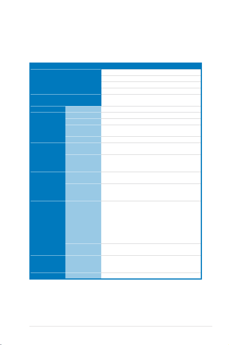
1.3 Systemspecications
The ASUS ESC1000 is a workstation featuring the ASUS P6T7 WS
SuperComputer motherboard. The workstation supports Intel® LGA1366
Xeon™ W3500 series processors, plus other latest technologies through the
chipsets onboard.
Model Name ESC1000
1 x Socket LGA1366
Processor / System Bus
Core Logic
ASUS Features Smart Fan
Total Slots
Capacity
Memory
Expansion Slots
Graphics
Storage
HDD Bays
Networking LAN
Memory Type
Memory Size
Total PCI/PCI-X/
PCI-E Slots
Slot Type
CUDA Support
Multi-GPU
Support
SATA Controller
SAS Controller
I = internal
A or S = hotswappable
Intel® Xeon W3500 series processors
Quad Core / Dual Core
Up to 6.4GT/s; Intel® QuickPatch Interconect
Intel® X58 + ICH10R
2 x NVIDIA® NF200
√
6 (3-channel per CPU, 6 DIMM per CPU)
Maximum up to 24GB
DDR3 1333 / 1066 non-ECC/ECC unbuffered
DIMM
1GB, 2GB and 4GB (UDIMM)
7
3 x PCI-E 2.0 x16 slots (at x16 or x8 link)
3 x PCI-E 2.0 x16 slots (x8 link)
1 x PCI-E 2.0 x16 slot (at x16 link)
Up to 3 Tesla C1060 cards + 1 Quadro FX5800
card / 1 Quadro FX370 card
Supports NVIDIA® 3-Way SLI™ technology
Supports ATI® CrossFireX™ technology, up to
Quad CrossFireX
Intel® ICH10R:
- 6 x SATA2 300MB/s ports
- Intel Matrix Storage (for Windows only)
supporting software RAID 0, 1, 5 & 10
Marvell 88SE6121 SATA controller:
- 2 x eSATA2 300MB/s ports supporting
RAID 0 & 1
Marvell 88SE6320 SAS controller
- 2 x SAS ports supporting RAID 0 & 1
4 x Hot-swap 3.5” HDD Bays
2 x Realtek® 8111C Gb LAN
(continued on the next page)
ASUS ESC1000 1-3
Page 16

Auxiliary Storage FDD / CD /
DVD
3 x 5.25” media bays (Option: DVD-RW)
1 x PS/2 Keyboard / Mouse combo port
1 x S/PDIF Out (Coaxial + Optical)
Rear I/O
2 x External SATA ports
2 x RJ45 ports
6 x USB 2.0/1.1 ports
8-channel Audio I/O
Windows® XP / Vista / 7 32 / 64-bit
OS Support
RedHat® Enterprise Linux AS5.3 32 / 64-bit
SuSE® Linux Enterprise Server 11 32 / 64-bit
(Subject to change without any notice)
Anti-virus Software
Dimension (HH x WW x DD)
Net Weight Kg (CPU, DRAM &
HDD not inclu ded)
Power Supply
Power Rating
Optional anti-virus CD Pack
445mm x 217.5mm x 545mm
20 Kg
1100W (80+) Single Power Supply
Input: 100-240Vac, 15-8A, 50-60Hz, Class I
Operation temperature: 10°C–35°C / Non operation
Environment
temperature: -40°C–70°C
Non operation humidity: 20% ~ 90% ( Non-
condensing)
*Specicationsaresubjecttochangewithoutnotice.
Chapter 1: Product introduction1-4
Page 17

1.4 Front panel features
The barebone workstation displays a simple yet stylish front panel with easily
accessible features. The power and reset buttons, LED indicators, optical drive,
and two USB ports are located on the front panel. For future installation of 5.25-inch
devices, two drive bays are available.
HDD access LED
Power LED
Optical drive
Empty 5.25-inch
bays
4-bay HDD cage
USB 2.0 ports
Refer to section 1.7.1 Front panel LEDs for the LED descriptions.
Security lock
Power button
Reset button
Headphone
outputjack
Microphone
jack
ASUS ESC1000 1-5
Page 18

1.5 Rear panel features
The rear panel includes a slot for the motherboard rear I/O ports, expansion slots,
a chassis lock and intrusion switch, a vent for the system fan, and power supply
module.
1100W 80+Single power
Power connector
supply
PS/2 keyboard/mouse
combo port
USB 2.0 ports
Optical S/PDIF Out port
USB 2.0 ports
External SATA ports
USB 2.0 ports
8-channel audio ports
Chassis lock
Coaxial S/PDIF Out port
LAN2 (RJ-45) port
120mm x 38mm system fan
LAN1 (RJ-45) port
Chassis intrusion switch
Expansion slots
Chapter 1: Product introduction1-6
Page 19

1.6 Internal features
The barebone workstation includes the basic components as shown.
6
1
7
2
9
3
4
5
1. 1100W 80+ Single Power supply unit
2. 120mm x 38mm system fan
3. ASUS P6T7 WS SuperComputer motherboard
4. Chassis intrusion switch
5. Expansion card locks
6. Optical drive
7. 2 x 5.25-inch drive bays
8. 4-bay HDD module
9. SATA/SAS backplane board
Turn off the system power and detach the power supply before removing or
replacing any system component.
The barebone workstation does not include a oppy disk drive and an optical
disc drive. Connect a USB oppy disk drive or a USB ODD to any of the USB
ports on the front or rear panel if you need to use a oppy disk or a optical disc.
8
*WARNING
HAZARDOUS MOVING PARTS
KEEP FINGERS AND OTHER BODY PARTS AWAY
ASUS ESC1000 1-7
Page 20

1.7 LED information
1.7.1 Front panel LEDs
HDD Access LED
Power LED
LED Icon Display status Description
Power LED ON System power ON
HDD Access LED
Drive status LED
OFF
Blinking
Green
Red
Green/Red blinking
No activity
Read/write data into the HDD
Bridge board connected to backplane
Installed HDD is in good condition
HDD failure
HDD rebuilding using the RAID card
Drive Status LED
The Power and HDD Access LEDs are visible even if the system front bezel is
closed.
1.7.2 Rear panel LEDs
Activity Link LED Speed LED
Status Description Status Description
OFF No link OFF 10 Mbps connection
ORANGE Linked ORANGE 100 Mbps connection
BLINKING Data activity GREEN 1 Gbps connection
Chapter 1: Product introduction1-8
ACT/LINK
LED
LAN port
SPEED
LED
Page 21

Chapter 2
This chapter lists the hardware setup
procedures that you have to perform
when installing or removing system
components.
ASUS ESC1000
Hardware setup
Page 22

2.1 Chassis cover
2.1.1 Removing the side cover
• Ensure that you unplug the power cord before removing the side cover.
• Take extra care when removing the side cover. Keep your ngers from
components inside the chassis that can cause injury, such as the CPU fan,
rear fan, and other sharp-edged parts.
• The images of the workstation shown in this section are for reference
purposes only and may not exactly match the model you purchase.
To remove the side cover
1. Remove the two screws that secure
the side cover.
1
1
2. Slide the side cover for about half
an inch toward the rear until it is
disengaged from the chassis.
3. Carefully lift the side cover and set
it aside.
2
Chapter 2: Hardware setup2-2
Page 23

2.1.2 Reinstalling the side cover
To reinstall the side cover
1. Match and insert the lower sliding
edge of the side cover to the
corresponding chassis edge.
2. Position the side cover to the
chassis.
3. Slide the side cover toward the
front panel until it snaps in place.
1
3
4. Drive in the two screws you
removed earlier to secure the side
cover.
4
4
2-3ASUS ESC1000
Page 24
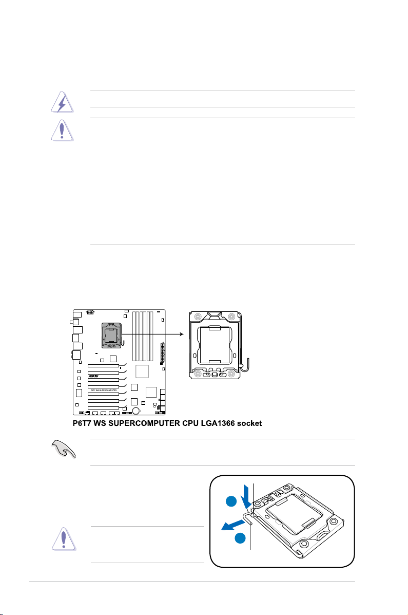
2.2 Central Processing Unit (CPU)
The motherboard comes with a surface mount LGA1366 socket designed for the
Intel® W3500 series processors.
Ensure that all power cables are unplugged before installing the CPU.
• Upon purchase of the motherboard, ensure that the PnP cap is on
the socket and the socket contacts are not bent. Contact your retailer
immediately if the PnP cap is missing, or if you see any damage to the PnP
cap/socket contacts/motherboard components. ASUS shoulders the repair
cost only if the damage is shipment/transit-related.
• Keep the cap after installing the motherboard. ASUS will process Return
Merchandise Authorization (RMA) requests only if the motherboard comes
with the cap on the LGA1366 socket.
• The product warranty does not cover damage to the socket contacts
resulting from incorrect CPU installation/removal, or misplacement/loss/
incorrect removal of the PnP cap.
2.2.1 Installing the CPU
To install a CPU:
1. Locate the CPU socket on the motherboard.
Before installing the CPU, ensure that the cam box is facing towards you and
the load lever is on your left.
2. Press the load lever with your
thumb (A), then move it to the left
(B) until it is released from the
retention tab.
To prevent damage to the socket
pins, do not remove the PnP cap
unless you are installing a CPU.
Retention tab
A
B
Load lever
Chapter 2: Hardware setup2-4
Page 25
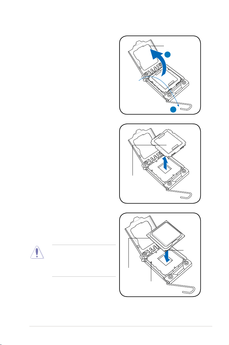
3. Lift the load lever in the direction of
the arrow to a 135º angle.
4. Lift the load plate with your thumb
and forenger to a 100º angle.
5. Remove the PnP cap from the CPU
socket.
Load plate
4
3
PnP cap
6. Position the CPU over the socket,
ensuring that the gold triangle is on
the bottom-left corner of the socket,
and then t the socket alignment key
into the CPU notch.
The CPU ts in only one correct
orientation. DO NOT force the
CPU into the socket to prevent
bending the connectors on the
socket and damaging the CPU!
Gold
triangle
mark
CPU notch
Alignment key
2-5ASUS ESC1000
Page 26
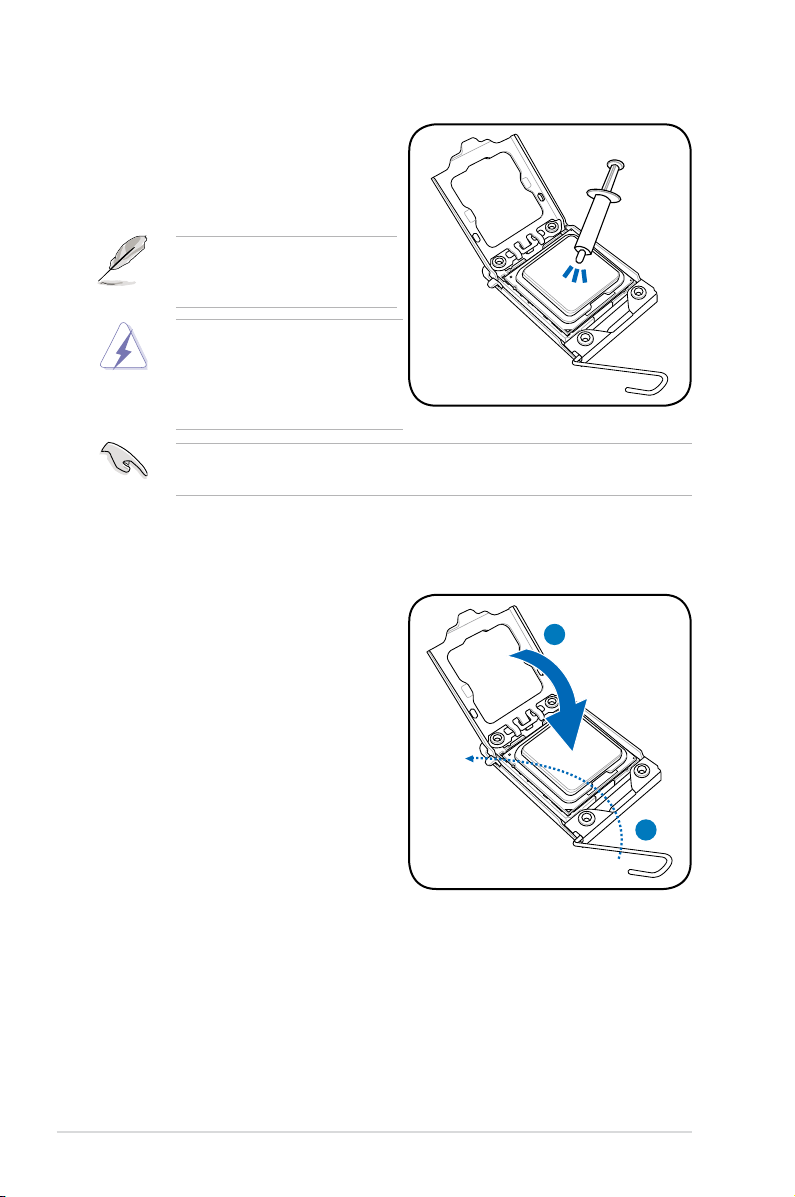
7. Apply several drops of thermal paste
to the exposed area of the CPU that
the heatsink will be in contact with,
ensuring that it is spread in an even
thin layer.
Some heatsinks come with preapplied thermal paste. If so, skip
this step.
The thermal paste is toxic and
inedible. If it gets into your eyes
or touches your skin, ensure to
wash it off immediately and seek
professional medical help.
To prevent contaminating the paste, DO NOT spread the paste with your nger
directly.
8. Close the load plate (A), and then
push the load lever (B) until it snaps
into the retention tab.
A
B
Chapter 2: Hardware setup2-6
Page 27
2.2.2 Installing the CPU heatsink and fan
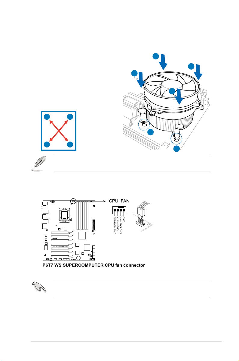
To install the CPU heatsink and fan
1. Place the heatsink on top of the
installed CPU, ensuring that the
four fasteners match the holes on
the motherboard.
B
A
B
2. Push down two fasteners at a time
in a diagonal sequence to secure
A
the heatsink and fan assembly in
place.
A
B
B
1
A
Orient the heatsink and fan assembly such that the CPU fan cable is closest to
the CPU fan connector.
1
3. Connect the CPU fan cable to the connector on the motherboard labeled
CPU_FAN.
DO NOT forget to connect the CPU fan connector! Hardware monitoring errors
can occur if you fail to plug this connector.
2-7ASUS ESC1000
Page 28

2.2.3 Uninstalling the CPU heatsink and fan
To uninstall the CPU heatsink and fan
1. Disconnect the CPU fan cable from
the connector on the motherboard.
2. Rotate each fastener
counterclockwise.
B
A
B
3. Pull up two fasteners at a time in
a diagonal sequence to disengage
A
the heatsink and fan assembly from
the motherboard.
A
B
B
A
4. Carefully remove the heatsink and fan assembly from the motherboard.
Chapter 2: Hardware setup2-8
Page 29
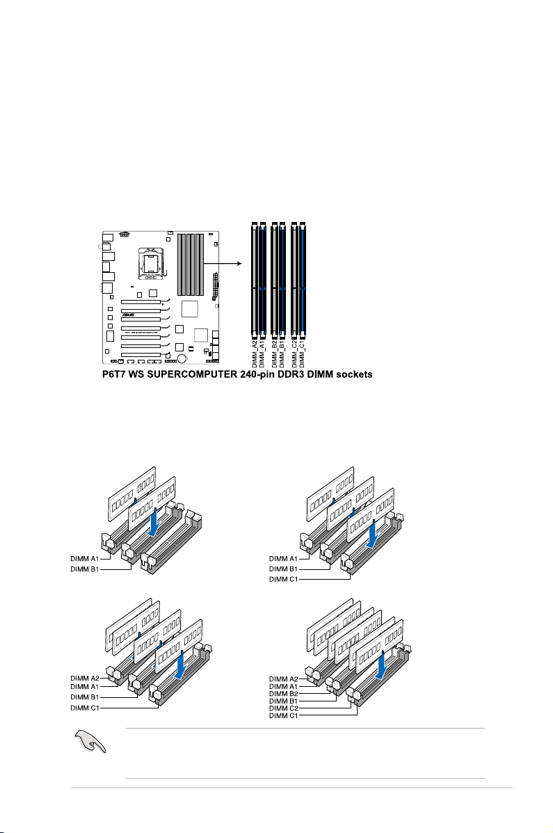
2.3 System memory
2.3.1 Overview
The motherboard comes with six Double Data Rate 3 (DDR3) Dual Inline Memory
Modules (DIMM) sockets.
A DDR3 module has the same physical dimensions as a DDR2 DIMM but is
notched differently to prevent installation on a DDR2 DIMM socket. DDR3 modules
are developed for better performance with less power consumption.
The gure illustrates the location of the DDR3 DIMM sockets:
Recommendedmemorycongurations
One DIMM:
You may install one memory module in slot A1, B1 or C1 as a single-channel
operation.
Two DIMMs (Dual-channel operation): Three DIMMs (Triple-channel operation):
Four DIMMs (Triple-channel operation):
Due to Intel CPU spec denition, the system will not boot if only one DIMM
is installed in DIMM slot A2, B2, or C2. Follow the illustrations above for
recommended memory conguration.
Six DIMMs (Triple-channel operation):
2-9ASUS ESC1000
Page 30

2.3.2 Memorycongurations
You may install 1GB, 2GB and 4GB ECC or non-ECC, unbuffered DDR3 DIMMs
into the DIMM sockets.
• You may install varying memory sizes in Channel A, Channel B and
Channel C. The system maps the total size of the lower-sized channel for
the dual-channel or triple-channel conguration. Any excess memory from
the higher-sized channel is then mapped for single-channel operation.
• Due to Intel spec denition, X.M.P. DIMMs and DDR3-1600 are supported
for one DIMM per channel only.
• According to Intel CPU spec, DIMMs with voltage requirement over 1.65V
may damage the CPU permanently. We recommend you install the DIMMs
with the voltage requirement below 1.65V.
• Always install DIMMs with the same CAS latency. For optimum
compatibility, we recommend that you obtain memory modules from the
same vendor.
• Due to the memory address limitation on 32-bit Windows OS, when you
install 4GB or more memory on the motherboard, the actual usable memory
for the OS can be about 3GB or less. For effective use of memory, we
recommend that you do any of the following:
- Use a maximum of 3GB system memory if you are using a 32-bit
Windows OS.
- Install a 64-bit Windows OS when you want to install 4GB or more on the
motherboard.
For more details, refer to the Microsoft® support site at
http://support.microsoft.com/kb/929605/en-us.
• This motherboard does not support DIMMs made up of 512 Mb (64MB)
chips or less (Memory chip capacity counts in Megabit, 8 Megabit/Mb = 1
Megabyte/MB).
• The default memory operation frequency is dependent on its SPD. Under
the default state, some memory modules for overclocking may operate at a
lower frequency than the vendor-marked value.
• For system stability, use a more efcient memory cooling system to support
a full memory load (6 DIMMs) or overclocking condition.
Chapter 2: Hardware setup2-10
Page 31

2.3.3 Installing a DIMM
Ensure to unplug the power supply before adding or removing DIMMs or other
system components. Failure to do so may cause severe damage to both the
motherboard and the components.
1. Unlock a DIMM socket by pressing
the retaining clips outward.
2. Align a DIMM on the socket
such that the notch on the DIMM
matches the break on the socket.
Unlocked retaining clip
A DIMM is keyed with a notch so that it ts in only one direction. DO NOT force
a DIMM into a socket to avoid damaging the DIMM.
2
DIMM notch
1
1
3. Firmly insert the DIMM into the
socket until the retaining clips snap
back in place and the DIMM is
properly seated.
Locked Retaining Clip
2.3.4 Removing a DIMM
Follow these steps to remove a DIMM.
1. Simultaneously press the
retaining clips outward to unlock
the DIMM.
1
Support the DIMM lightly with your ngers when pressing the retaining clips.
The DIMM might get damaged when it ips out with extra force.
2. Remove the DIMM from the socket.
3
2
1
2-11ASUS ESC1000
Page 32

2.4 Front panel assembly
Before you can install a 5.25-inch drive, you should rst remove the front panel
assembly (front bezel and front panel cover).
2.4.1 Removing the front panel assembly
To remove the front panel assembly
1. Locate the three hooked tabs on the chassisLocate the three hooked tabs on the chassis
side rail.
2. Shift the hooked tabs and take off the front
bezel.
2.4.2 Reinstalling the front panel assembly
To reinstall the front panel assembly:
1. Hook the other side of the front
panel assembly to the chassis.
2. Swing the front panel assembly and
snap it back into place.
Chapter 2: Hardware setup2-12
Page 33

2.5 5.25-inch drives
Ensure to unplug the power cable before installing or removing any system
components. Failure to do so may cause damage to the motherboard and other
system components!
The system comes with three 5.25-inch
drive bays located on the upper front
part of the chassis. An optical drive that
comes standard/optional with the system
package occupies the uppermost bay
(labeled 1). The lower bays (labeled 2
and 3) are available for additional 5.25inch optical, zip, or oppy disk drives.
You must remove the front panel
assembly before installing a
5.25-inch drive.
Installing a 5.25-inch drive
1. Unscrew and remove the metal
cover of the bay where you want to
install the 5.25-inch drive, and take
off the plastic cover on the front
bezel at the same position.
2. Insert the drive into the bay and
slide the bay lock to the right until it
clicks in place.
1
2
3
2
3. Connect the SATA cable to the
SATA connector on the back of the
drive.
4. Connect a power plug from
the power supply to the power
connector on the back of the drive.
4
3
2-13ASUS ESC1000
Page 34

2.6 SATA hard disk drives
The hard disk drive module cage on the front panel, including externally removable
trays for mounting SATA hard disk drives, allows you to access the drive trays by
simply opening the front bezel.
An HDD module cage comes with a SATA backplane. Ensure of the type of HDD
module cage you purchase before buying hard disks.
2.6.1 Installing the HDD module cage
1. Examine the chassis and ensure the bay space is free of wires and other
obstructions.
2. Level the HDD module cage latch
counterclockwise.
3. Insert the HDD module cage into the
bay.
2
4. When the HDD module cage is
completed inserted, the cage latch
will be pushed back clockwise.
4
3
5. Lock the cage latch properly.
6. Connect the appropriate cables to
the SATA backplane on the HDD
module cage.
5
Chapter 2: Hardware setup2-14
Page 35

2.6.2 Removing the HDD module cage
1. Disconnect the all cables from the SATA backplane on the HDD module cage.
2. Level the HDD module cage latch
counterclockwise. The HDD module
cage will be pushed out of the
chassis.
2
3. Completely pull out the HDD module
cage.
2.6.3 Installing a hot-swap SATA hard disk drive
1. Release a drive tray by pushing the
spring lock to the right, and then
pulling the tray lever outward. The
drive tray ejects slightly after you
pull out the lever.
2-15ASUS ESC1000
Page 36

2. Firmly hold the tray lever and pull
the drive tray out of the bay.
3. Take note of the drive tray holes.
Each side has three holes to t
different types of hard disk drives.
Use two screws on each side to
secure the hard disk drive.
4. Place a SATA hard disk drive on
the tray, and then secure it with four
screws.
5. Carefully insert the drive tray and
push it all the way to the depth of
the bay until just a small fraction of
the tray edge protrudes.
When installed, the SATA connector on the drive connects to the SATA interface
on the backplane.
Chapter 2: Hardware setup2-16
Page 37

6. Push the tray lever until it clicks,
and secures the drive tray in place.
The drive tray is correctly placed
when its front edge aligns with the
bay edge.
7. Repeat steps 1 to 6 if you wish to
install a second SATA drive.
2.6.4 Removing and reinstalling the backplane
DO NOT remove the backplane unless necessary!
1. Remove all hot-swap HDD trays
from the chassis.
2. Disconnect all cables from the SATA
backplane.
3. Loosen the four screws on the
backplane.
4. Firmly hold the backplane, lift it up
and remove it from the module.
5. Follow the previous instructions in
reverse to reinstall the backplane.
2-17ASUS ESC1000
Page 38

2.7 Expansion cards
The system is designed with an expansion card lock on the rear panel for you to
install or remove an expansion card in less steps.
Ensure to unplug the power cord before installing or removing expansion cards.
Failure to do so may cause severe damage to the motherboard and other
system components!
2.7.1 Installing an expansion card
1. Before installing the expansion card, read the documentation that came with
it and make the necessary hardware settings for the card.
2. Lay the system on its side on a at, stable surface.
3. Push down the expansion cardexpansion card
lock latch (step a) and lift up the
expansion card lock (step b), as
shown in the right gure.
Expansion card lock latches
Expansion card locks
4. Remove the metal slot cover
opposite the slot where you wish to
install an expansion card.
a
b
5. Align the card golden ngers with
the slot, and then press rmly until
the card is completely seated on
the slot.
Chapter 2: Hardware setup2-18
Page 39

6. Restore the expansion card lock
to its original position. A light click
indicates that the card is locked in
place.
2-19ASUS ESC1000
Page 40

2.7.2 Conguringanexpansioncard
After installing the expansion card, congure the it by adjusting the software settings.
1. Turn on the system and change the necessary BIOS settings, if any. See
Chapter 5 for information on BIOS setup.
2. Assign an IRQ to the card. Refer to the following tables.
3. Install the software drivers for the expansion card.
Standard interrupt assignments
IRQ Priority Standard function
0 1 System Timer
1 2 Keyboard Controller
2 – Redirect to IRQ#9
4 12 Reserved
5 13 Reserved
6 14 Floppy Disk Controller
7 15 Reserved
8 3 System CMOS/Real Time Clock
9 4 Reserved
10 5 Reserved
11 6 Reserved
12 7 Reserved
13 8 Numeric Data Processor
14 9 Reserved
IRQ assignments for this motherboard
LAN1 (8111C) – shared – – – – – –
LAN2 (8111C) – – shared – – – – –
Marvell 6121 – – – shared – – – –
Marvell SAS shared – – – – – – –
USB controller 1 – – – – – – – shared
USB controller 2 – – – shared – – – –
USB controller 3 – – shared – – – – –
USB controller 4 shared – – – – – – –
USB controller 5 – – – – – shared – –
USB controller 6 – – – shared – – – –
USB 2.0 controller 1 – – – – – – – shared
USB 2.0 controller 2 – – shared – – – – –
SATA controller 1 – – – – shared – – –
SATA controller 2 – – – – shared – – –
1394 – shared – – – – – –
Audio Azalia – – – – – – shared –
A B C D E F G H
Chapter 2: Hardware setup2-20
Page 41

2.8 Cable connections
• The bundled system cables are pre-connected before shipment. You do
not need to disconnect these cables unless you will remove pre-installed
components to install additional devices.
• Refer to Chapter 3 for detailed information on the connectors.
2.8.1 Motherboard connections
2
3
1
3
3
5
4 6 78
Standard cables connected to the motherboard
1. 24-pin ATX power connector (from power supply to motherboard)
2. 8-pin 12V power connector (from power supply to motherboard)
3. System fan connector (from system fan to motherboard)
4. Front panel USB connector (from motherboard to front I/O board)
5. SATA conectors (from motherboard to SATA backplane)
6. Chassis Intrusion connector (from rear chassis intrusion switch to
motherboard)
7. System panel connector (from motherboard to front I/O board)
8. Front panel audio connector (from motherboard to front I/O board)
2-21ASUS ESC1000
Page 42

2.8.2 SATA backplane connections
An SATA backplane comes pre-installed in the ESC1000. The SATA backplane has
four 22-pin SATA connectors to support Serial ATA hard disk drives. The backplane
design incorporates a hot swap feature to allow easy connection or removal of
SATA hard disks. The LEDs on the backplane connect to the front panel LEDs to
indicate HDD status. See section 1.7 LED information for details.
Front side
The front side of the SATA backplane faces the front panel when installed. This
side includes four SATA connectors for the hot swap drive trays.
HDD1
HDD2
Drive status LEDs
HDD3
HDD4
Each SATA connector is labeled (HDD1, HDD2,
HDD3, HDD4) so you can easily determine
their counterpart connectors at the back side of
the backplane. Refer to the table for reference.
HDD Device Front side connector Back side connector
HDD 1 HDD1 CON11
HDD 2 HDD2 CON22
HDD 3 HDD3 CON33
HDD 4 HDD4 CON44
Chapter 2: Hardware setup2-22
Page 43

Back side
The back side of the SATA backplane faces the rear panel when installed. This
side includes the power connectors and SATA interfaces for the motherboard Serial
ATA connectors.
U1
CON1
CON2
CON4
CON3
Connectors Description
U1
CON1/CON2/
CON3/CON4
Connects to 4-pin plug of the power supply
Connects to SATA/SAS connectors on the motherboard
2-23ASUS ESC1000
Page 44

2.9 Removable components
You may need to remove previously installed system components when installing
or removing system devices, or when you need to replace defective components.
This section tells how to remove the following components:
1. Rear system fan
2. Front system fan
2.9.1 Removing rear system fan
To remove the rear system fan
1. Unplug the system fan cable from
the
CHA_FAN1
motherboard.
connector on the
2. Shift the two hooked tabs leftward
and rightward respectively.
Chapter 2: Hardware setup2-24
Page 45

3. Carefully take off the system fan.take off the system fan.
4. Follow the previous instructions in
reverse to reinstall the rear system
fan.
2.9.2 Removing front system fan
To remove the front system fan
1. Remove the two screws that secure
the right side cover.
1
2. Locate the front system fan near
the 5.25-inch drive bays.
3. Squeeze the front system fan
latches (step a) and pull out the
front system fan (step b), as shown
in the right gure.
4. Follow the previous instructions in
reverse to reinstall the front system
fan.
1
a
b
a
2-25ASUS ESC1000
Page 46

Chapter 2: Hardware setup2-26
Page 47

Chapter 3
This chapter includes the motherboard
layout and brief descriptions of the
jumpers and internal connectors.
ASUS ESC1000
Motherboard Info
Page 48

3.1 Motherboard layout
Refer to 3.3 Connectors for more information about rear panel connectors and
internal connectors.
Chapter 3: Motherboard information3-2
Page 49

Layout contents
Connectors/Jumpers/Slots Page
1. ATX power connectors (24-pin EATXPWR, 8-pin EATX12V) 3-14
2. LGA1366 CPU Socket 2-4
3. CPU, chassis, and power fan connectors (4-pin CPU_FAN,
3-pin CHA_FAN1-3, 3-pin PWR_FAN)
4. DDR3 DIMM slots 2-9
5. CPU / DRAM Bus / QPI DRAM overvoltage settings (3-pin
OV_CPU; 3-pin OV_DRAM_Bus; 3-pin OV_QPI_DRAM)
6. MarvellMarvell® 88SE6320 SAS RAID connector [black]
(7-pin SAS1-2)
7. ICH10R Serial ATA connectors [blue] (7-pin SATA1-6) 3-9
8. Chassis intrusion connector (4-1 pin CHASSIS)Chassis intrusion connector (4-1 pin CHASSIS) 3-13
9. System panel connector (20-8 pin PANEL) 3-16
10. Clear RTC RAM (3-pin CLRTC) 3-4
11. Standby power LED (SB_PWR)Standby power LED (SB_PWR) 3-18
12. TPM connector (20-1 pin TPM) 3-8
13. IEEE 1394a port connector (10-1 pin IE1394_2) 3-8
14. USB connectors (10-1 pin USB78, USB910, USB1112) 3-11
15. Digital audio connector (4-1 pin SPDIF_OUT)Digital audio connector (4-1 pin SPDIF_OUT) 3-15
16. Optical drive audio connector (4-pin CD) 3-15
17. Front panel audio connector (10-1 pin AAFP) 3-13
3-12
3-5
3-10
ASUS ESC1000 3-3
Page 50

3.2 Jumpers
1. Clear RTC RAM (CLRTC)
This jumper allows you to clear the Real Time Clock (RTC) RAM in
CMOS. You can clear the CMOS memory of date, time, and system setup
parameters by erasing the CMOS RTC RAM data. The onboard button
cell battery powers the RAM data in CMOS, which include system setup
information such as system passwords.
To erase the RTC RAM
1. Turn OFF the computer and unplug the power cord.
2. Move the jumper cap from pins 1-2 (default) to pins 2-3. Keep the cap on
pins 2-3 for about 5–10 seconds, then move the cap back to pins 1-2.
3. Plug the power cord and turn ON the computer.
4. Hold down the <Del> key during the boot process and enter BIOS setup
to re-enter data.
Except when clearing the RTC RAM, never remove the cap on CLRTC jumper
default position. Removing the cap will cause system boot failure!
• If the steps above do not help, remove the onboard battery and move
the jumper again to clear the CMOS RTC RAM data. After the CMOS
clearance, reinstall the battery.
• You do not need to clear the RTC when the system hangs due to
overclocking. For system failure due to overclocking, use the C.P.R. (CPU
Parameter Recall) feature. Shut down and reboot the system so the BIOS
can automatically reset parameter settings to default values.
• Due to the chipset behavior, AC power off is required to enable C.P.R.
function. You must turn off and on the power supply or unplug and plug the
power cord before rebooting the system.
Chapter 3: Motherboard information3-4
Page 51

2. CPU / DRAM Bus / QPI DRAM overvoltage setting (3-pin OV_CPU, 3-pin
OV_DRAM_BUS, 3-pin OV_QPI_DRAM)
These jumpers allow you to enable or disable the advanced CPU, DRAM
Bus, and QPI DRAM overvoltage settings in BIOS. Read the following
information before you change the jumper settings.
OV_CPU OV_DRAM_BUS OV_QPI_DRAM
Pins 1-2 (Default) up to 1.70V up to 1.90V up to 1.70V
Pins 2-3 (OV Enabled) up to 1.9V up to 2.46V up to 1.9V
• Before you change the jumper settings for extra-high overvoltage ability,
use the BIOS items rst to adjust the desired CPU, DRAM, and QPI
performance. Ensure your system functions well under the highest BIOS
voltage settings before you change the setting of these three jumpers.
• DO NOT set the OV_CPU jumper to pins 2–3 when you install a new CPU
and have not booted for the rst time. Doing so may cause the system to
halt. For system failure due to the wrong setting of the OV_CPU jumper,
shut down the computer and move the cap back to pins 1–2.
• According to Intel CPU spec, DIMMs with voltage requirement over 1.65V
may damage the CPU permanently. We recommend you install the DIMMs
with the voltage requirement below 1.65V.
• The system may need a better cooling system (for example, a watercooling system) to work stably under high voltage settings.
ASUS ESC1000 3-5
Page 52

3.3 Connectors
3.3.1 Rear panel connectors
1. PS/2 keyboard / mouse combo port. This port is for a PS/2 keyboard or a
PS/2 mouse.
2. Coaxial S/PDIF Out port. This port connects an external audio output device
via a coaxial S/PDIF cable.
3. LAN 2 (RJ-45) port. This Marvell® LAN port allows Gigabit connection to a
Local Area Network (LAN) through a network hub. Refer to the table below
for the LAN port LED indications.
4. LAN 1 (RJ-45) port. This Marvell® LAN port allows Gigabit connection to a
Local Area Network (LAN) through a network hub. Refer to the table below
for the LAN port LED indications.
*To compliant with Energy Star 4.0, LAN 1 and LAN 2 ports do not support
WOL (Wake on LAN) function.
LAN port LED indications
Activity Link LED Speed LED
Status Description Status Description
OFF No link OFF 10 Mbps connection
ORANGE Linked ORANGE 100 Mbps connection
BLINKING Data activity GREEN 1 Gbps connection
ACT/LINK
LED
LAN port
SPEED
LED
5. Center/Subwoofer port (orange). This port connects the center/subwoofer
speakers.
6. Rear Speaker Out port (black). This port connects the rear speakers in a
4-channel, 6-channel, or 8-channel audio conguration..
7. Line In port (light blue). This port connects the tape, CD, DVD player, or
other audio sources.
Chapter 3: Motherboard information3-6
Page 53

8. Line Out port (lime). This port connects a headphone or a speaker. In
4-channel, 6-channel, and 8-channel conguration, the function of this port
becomes Front Speaker Out.
9. Microphone port (pink). This port connects a microphone.
10. Side Speaker Out port (gray). This port connects the side speakers in an
8-channel audio conguration.
Refer to the audio conguration table below for the function of the audio ports in
2, 4, 6, or 8-channel conguration.
Audio2,4,6,or8-channelconguration
Port
Light Blue Line In Line In Line In Line In
Lime Line Out Front Speaker Out Front Speaker Out Front Speaker Out
Pink Mic In Mic In Mic In Mic In
Orange – – Center/Subwoofer Center/Subwoofer
Black – Rear Speaker Out Rear Speaker Out Rear Speaker Out
Gray – – – Side Speaker Out
11. USB 2.0 ports 1 and 2. These 4-pin Universal Serial Bus (USB) ports are
available for connecting USB 2.0 devices.
12. External SATA port. This port connects to an external a Serial ATA hard disk
drive.
Headset
2-channel
4-channel 6-channel 8-channel
DO NOT insert a different connector to the external SATA port.
13. USB 2.0 ports 3 and 4. These 4-pin Universal Serial Bus (USB) ports are
available for connecting USB 2.0 devices.
14. Optical S/PDIF Out port. This port connects an external audio output device
via an optical S/PDIF cable.
15. USB 2.0 ports 5 and 6. These 4-pin Universal Serial Bus (USB) ports are
available for connecting USB 2.0 devices.
ASUS ESC1000 3-7
Page 54

3.3.2 Internal connectors
1. TPM connector (20-1 pin TPM) [Optional]
This connector supports a Trusted Platform Module (TPM) system, which can
securely store keys, digital certicates, passwords, and data. A TPM system
also helps enhance network security, protects digital identities, and ensures
platform integrity.
The TPM module is purchased separately.
2. IEEE 1394a port connector (10-1 pin IE1394_2)
This connector is for an IEEE 1394a port. Connect the IEEE 1394a module
cable to this connector, then install the module to a slot opening at the back
of the system chassis.
Never connect a USB cable to the IEEE 1394a connector. Doing so will damage
the motherboard!
You can attach a FireWire/1394 cable to this connector if your chassis suppots
the front panel IEEE1394 port.
Chapter 3: Motherboard information3-8
Page 55

3. ICH10R Serial ATA connectors [blue] (7-pin SATA 1-6)
These connectors are for the Serial ATA signal cables for Serial ATA hard disk
drives and optical disc drives.
If you installed Serial ATA hard disk drives, you can create a RAID 0, 1, 5,
and 10 conguration with the Intel® Matrix Storage Technology through the
onboard Intel® ICH10R RAID controller.
• These connectors are set to IDE mode by default. If you intend to create
a Serial ATA RAID set using these connectors, set the Congure SATA as
item in the BIOS to [RAID]. See section
details.
• Before creating a RAID set, refer to section
manual bundled in the motherboard support DVD.
• When using hot-plug and NCQ, set the
[AHCI]. Refer to section
• You must install Windows® XP Service Pack 2 or later version before using
Serial ATA hard disk drives. The Serial ATA RAID feature is available only if
you are using Windows® XP SP2 or later version.
ASUS ESC1000 3-9
4.3.5StorageConguration
4.3.5StorageConguration
5.1.RAIDcongurations
CongureSATAas
in the BIOS to
for details.
for
or the
Page 56

4. Marvell® 88SE6320 SAS RAID connectors [black] (7-pin SAS1-2)
These connectors are for SAS (Serial Attached SCSI) signal cables that
support SAS hard disk drives. To congure RAID 0 or RAID 1, install two SAS
hard disk drives to these two connectors.
• When ICH10R SATA ports are set to RAID or AHCI mode, SAS HDDs can
be detected in Windows environment only.
• Please install the Marvell® Controller driver before using the black SAS
RAID connectors (SAS1-2). See section 6.3.2 Drivers menu for details.
• Before creating a RAID set, see section 5.3 Marvell® SAS RAID
congurations for details..
Before creating a RAID set using SAS hard disk drives, ensure that you have
connected the SAS signal cables and installed SAS hard disk drives; otherwise,
you cannot enter the Marvell RAID utility and SAS BIOS setup during POST.
Chapter 3: Motherboard information3-10
Page 57

5. USB connectors (10-1 pin USB78, USB910, USB1112)
These connectors are for USB 2.0 ports. Connect the USB module cable
to any of these connectors, then install the module to a slot opening at the
back of the system chassis. These USB connectors comply with USB 2.0
specication that supports up to 480 Mbps connection speed.
Never connect a 1394 cable to the USB connectors. Doing so will damage the
motherboard!
If your chassis suppots front panel USB ports, you can attach a front panel
USB cable to these connectors. Connect the USB cable to ASUS Q-Connector
(USB, blue) rst, and then install the Q-Connector (USB) to the USB connector
onboard.
ASUS ESC1000 3-11
Page 58

6. CPU, chassis and power fan connectors
(4-pin CPU_FAN, 3-pin CHA_FAN1-3, 3-pin PWR_FAN)
The fan connectors support cooling fans of 350 mA ~ 2000 mA (24 W max.)
or a total of 1 A ~ 7 A (84 W max.) at +12V. Connect the fan cables to the fan
connectors on the motherboard, ensuring that the black wire of each cable
matches the ground pin of the connector.
DO NOT forget to connect the fan cables to the fan connectors. Insufcient air
ow inside the system may damage the motherboard components. These are
not jumpers! Do not place jumper caps on the fan connectors!
Chapter 3: Motherboard information3-12
Page 59

7. Front panel audio connector (10-1 pin AAFP)
This connector is for a chassis-mounted front panel audio I/O module that
supports either HD Audio or legacy AC`97 audio standard. Connect one end
of the front panel audio I/O module cable to this connector.
• We recommend that you connect a high-denition front panel audio module
to this connector to avail of the motherboard’s high-denition audio capability.
• If you want to connect a high-denition front panel audio module to this
connector, ensure that the Front Panel Type item in the BIOS is set to [HD
Audio]. If you want to connect an AC' 97 front panel audio module to this
connector, set the item to [AC97]. See page 4-25 or details.
8. Chassis intrusion connector (4-1 pin CHASSIS)
This connector is for a chassis-mounted intrusion detection sensor or switch.
Connect one end of the chassis intrusion sensor or switch cable to this
connector. The chassis intrusion sensor or switch sends a high-level signal to
this connector when a chassis component is removed or replaced. The signal
is then generated as a chassis intrusion event.
By default , the pin labeled “Chassis Signal” and “Ground” are shorted with
a jumper cap. Remove the jumper caps only when you intend to use the
chassis intrusion detection feature.
ASUS ESC1000 3-13
Page 60

9. ATX power connectors (24-pin EATXPWR, 8-pin EATX12V)
These connectors are for ATX power supply plugs. The power supply plugs
are designed to t these connectors in only one orientation. Find the proper
orientation and push down rmly until the connectors completely t.
• Do not forget to connect the 8-pin EATX12 V power plug; otherwise, the
system will not boot.
• Use of a PSU with a higher power output is recommended when conguring
a system with more power-consuming devices. The system may become
unstable or may not boot up if the power is inadequate.
• If you are uncertain about the minimum power supply requirement for your
system, refer to the Recommended Power Supply Wattage Calculator
at
http://support.asus.com/PowerSupplyCalculator/PSCalculator.
aspx?SLanguage=en-us
for details.
Chapter 3: Motherboard information3-14
Page 61

10. Optical drive audio connector (4-pin CD)
This connector allows you to receive stereo audio input from sound sources
such as a CD-ROM, TV tuner, or MPEG card.
11. Digital audio connector (4-1 pin SPDIF_OUT)
This connector is for an additional Sony/Philips Digital Interface (S/PDIF)
port(s). If you are using ASUS HDMI-equipped graphics card, connect the
HDMI card to this connector with a S/PDIF out cable.
The S/PDIF out cable is purchased separately.
ASUS ESC1000 3-15
Page 62

12. System panel connector (20-8 pin PANEL)
This connector supports several chassis-mounted functions.
•
System power LED (2-pin PLED)
This 2-pin connector is for the system power LED. Connect the chassis
power LED cable to this connector. The system power LED lights up when
you turn on the system power, and blinks when the system is in sleep mode.
•
Hard disk drive activity LED (2-pin IDE_LED)
This 2-pin connector is for the HDD Activity LED. Connect the HDD Activity
LED cable to this connector. The IDE LED lights up or ashes when data is
read from or written to the HDD.
•
System warning speaker (4-pin SPEAKER)
This 4-pin connector is for the chassis-mounted system warning speaker. The
speaker allows you to hear system beeps and warnings.
•
ATX power button/soft-off button (2-pin PWRSW)
This connector is for the system power button. Pressing the power button
turns the system on or puts the system in sleep or soft-off mode depending
on the BIOS settings. Pressing the power switch for more than four seconds
while the system is ON turns the system OFF.
•
Reset button (2-pin RESET)
This 2-pin connector is for the chassis-mounted reset button for system
reboot without turning off the system power.
Chapter 3: Motherboard information3-16
Page 63

3.3.3. ASUS Q-Connector (system panel)
IDE_LED
POWER SW
RESET SW
IDE_LED-
IDE_LED+
PWR
Reset
Ground
Ground
Use the ASUS Q-Connector to connect/disconnect the chassis front panel cables.
1. Connect the front panel cables to the
ASUS Q-Connector.
Refer to the labels on the Q-Connector
to know the detailed pin denitions, and
then match them to their respective
front panel cable labels.
The labels on the front panel
cables may vary depending on
the chassis model.
2. Install the ASUS Q-Connector to the
system panel connector, ensuring the
orientation matches the labels on the
motherboard.
3. The front panel functions are now
enabled. The gure shows the
Q-Connector is properly installed on the
motherboard.
ASUS ESC1000 3-17
Page 64

3.4 Internal LEDs
Standby Power LED
The motherboard comes with a standby power LED. The green LED lights up
to indicate that the system is ON, in sleep mode, or in soft-off mode. This is a
reminder that you should shut down the system and unplug the power cable before
removing or plugging in any motherboard component. The illustration below shows
the location of the onboard LED.
Chapter 3: Motherboard information3-18
Page 65

Chapter 4
This chapter tells how to change the
system settings through the BIOS Setup
menus. Detailed descriptions of the BIOS
parameters are also provided.
ASUS ESC1000
BIOS setup
Page 66

4.1 Managing and updating your BIOS
The following utilities allow you to manage and update the motherboard Basic
Input/Output System (BIOS) setup.
1. ASUS Update: Updates the BIOS in Windows® environment.
2. ASUS EZ Flash 2: Updates the BIOS using a USB ash drive.
3. ASUS CrashFree BIOS 3 utility: Restores the BIOS using the motherboard
support DVD or a USB ash drive when the BIOS le fails or gets corrupted.
Refer to the corresponding sections for details on these utilities.
Save a copy of the original motherboard BIOS le to a USB ash drive in case
you need to restore the BIOS in the future. Copy the original motherboard BIOS
using the ASUS Update utility.
4.1.1 ASUS Update utility
The ASUS Update is a utility that allows you to manage, save, and update the
motherboard BIOS in Windows® environment. The ASUS Update utility allows you
to:
• Save the current BIOS le
• Download the latest BIOS le from the Internet
• Update the BIOS from an updated BIOS le
• Update the BIOS directly from the Internet
• View the BIOS version information
This utility is available in the support DVD that comes with the motherboard
package.
ASUS Update requires an Internet connection either through a network or an
Internet Service Provider (ISP).
Installing ASUS Update
To install ASUS Update:
1. Place the support DVD in the optical drive.
2. From the Main menu, click the Utilities tab, and then click Install ASUS
Update VX.XX.XX.
3. The ASUS Update utility is copied to your system.
4-2 Chapter 4: BIOS setup
Page 67

Updating the BIOS through the Internet
Quit all Windows® applications before you update the BIOS using this utility.
To update the BIOS through the Internet
1. From the Windows® desktop,
click Start > Programs > ASUS
> ASUSUpdate > ASUSUpdate.
The ASUS Update main window
appears.
3. Select the ASUS FTP site
nearest you to avoid network
trafc, or click Auto Select. Click
Next.
2. Select Update BIOS from the
Internet from the drop-down
menu, and then click Next.
4. From the FTP site, select the BIOS
version that you wish to download.
Click Next.
ASUS ESC1000 4-3
Page 68

5. Follow the onscreen instructions to complete the update process.
The ASUS Update utility is capable of updating itself through the Internet.
Always update the utility to avail all its features.
UpdatingtheBIOSthroughaBIOSle
To update the BIOS through a BIOS le
1. Fom the Windows® desktop, click
Start > Programs > ASUS >
ASUSUpdate > ASUSUpdate.
The ASUS Update main window
appears.
2. Select Update BIOS fromale
from the dropdown menu, then
click Next.
3. Locate the BIOS le from the
Open window, then click Open.
4. Follow the onscreen instructions
to complete the update process.
P6T7WS.ROM
P6T7WS
Ensure to load the BIOS
default settings to ensure
system compatibility and
stability. Select the Load Setup
Defaults item under the Exit
menu. Refer to section 4.9 Exit
Menu for details.
4-4 Chapter 4: BIOS setup
Page 69

4.1.2 ASUS EZ Flash 2 utility
The ASUS EZ Flash 2 feature allows you to update the BIOS without having to use
a bootable oppy disk or an OS-based utility.
Before you start using this utility, download the latest BIOS from the ASUS
website at www.asus.com.
To update the BIOS using EZ Flash 2
1. Insert the USB ash drive that contains the latest BIOS le to the USB port,
and then launch EZ Flash 2 in any of these two ways:
• Press <Alt> + <F2> during POST to display the following.
• Enter the BIOS setup program. Go to the Tools menu to select EZ Flash
2 and press <Enter> to enable it.
ASUSTek EZ Flash 2 BIOS ROM Utility V3.38
FLASH TYPE: MXIC 25L1605A
Current ROM
BOARD: P6T7 WS SUPERCOMPUTER
VER: 0402
DATE: 07/30/2009
PATH: A:\
A:
Note
[Enter] Select or Load [Tab] Switch [V] Drive Info
[Up/Down/Home/End] Move [B] Backup [Esc] Exit
Update ROM
BOARD: Unknown
VER: Unknown
DATE: Unknown
2. Press <Tab> to switch between drives until the correct BIOS le is
found. When found, EZ Flash 2 performs the BIOS update process and
automatically reboots the system when done.
• This function can support devices such as a USB ash drive with FAT 32/16
format and single partition only.
• DO NOT shut down or reset the system while updating the BIOS to prevent
system boot failure!
Ensure to load the BIOS default settings to ensure system compatibility and
stability. Select the Load Setup Defaults item under the Exit menu. Refer to
section 4.9 Exit Menu for details.
ASUS ESC1000 4-5
Page 70

4.1.3 ASUS CrashFree BIOS 3 utility
The ASUS CrashFree BIOS 3 utility is an auto recovery tool that allows you to
restore the BIOS le when it fails or gets corrupted during the updating process.
You can restore a corrupted BIOS le using the motherboard support DVD or a
USB ash drive that contains the BIOS le.
The BIOS le in the motherboard support DVD may be older than the BIOS le
published on the ASUS ofcial website. If you want to use the newer BIOS le,
download the le at support.asus.com and save it to a USB ash drive.
Recovering the BIOS
To recover the BIOS
1. Turn on the system.
2. Insert the motherboard support DVD to the optical drive, or the USB ash
drive containing the BIOS le to the USB port.
3. The utility automatically checks the devices for the BIOS le. When found,
the utility reads the BIOS le and starts ashing the corrupted BIOS le.
4. Turn off the system after the utility completes the updating process and
power on again.
5. The system requires you to enter BIOS Setup to recover BIOS setting. To
ensure system compatibility and stability, we recommend that you press
<F2> to load default BIOS values.
DO NOT shut down or reset the system while recovering the BIOS! Doing so
can cause system boot failure!
4-6 Chapter 4: BIOS setup
Page 71

4.2 BIOS setup program
This motherboard supports a programmable rmware chip that you can update
using the provided utility described in section 4.1 Managing and updating your
BIOS.
Use the BIOS Setup program when you are installing a motherboard, reconguring
your system, or prompted to “Run Setup.” This section explains how to congure
your system using this utility.
Even if you are not prompted to use the Setup program, you can change the
conguration of your computer in the future. For example, you can enable the
security password feature or change the power management settings. This
requires you to recongure your system using the BIOS Setup program so that the
computer can recognize these changes and record them in the CMOS RAM of the
rmware chip.
The rmware chip on the motherboard stores the Setup utility. When you start up
the computer, the system provides you with the opportunity to run this program.
Press <Del> during the Power-On Self-Test (POST) to enter the Setup utility;
otherwise, POST continues with its test routines.
If you wish to enter Setup after POST, restart the system by pressing
<Ctrl+Alt+Delete>, or by pressing the reset button on the system chassis. You can
also restart by turning the system off and then back on. Do this last option only if
the rst two failed.
The Setup program is designed to make it as easy to use as possible. Being a
menu-driven program, it lets you scroll through the various sub-menus and make
your selections from the available options using the navigation keys.
• The default BIOS settings for this motherboard apply for most conditions
to ensure optimum performance. If the system becomes unstable after
changing any BIOS settings, load the default settings to ensure system
compatibility and stability. Select the Load Setup Defaults item under the
Exit Menu. Refer to section 4.9 Exit Menu.
• The BIOS setup screens shown in this section are for reference purposes
only, and may not exactly match what you see on your screen.
• Visit the ASUS website (www.asus.com) to download the latest BIOS le for
this motherboard.
ASUS ESC1000 4-7
Page 72

4.2.1 BIOS menu screen
Menu bar
Main Ai Tweaker Advanced Power Boot Tools Exit
System Time [11:51:25]
System Date [Fri 03/20/2009]
Language [English]
SATA1 [HDT722516DLA380]
SATA2 [Not Detected]
SATA3 [ATAPI DVD DH1]
SATA4 [Not Detected]
SATA5 [Not Detected]
SATA6 [Not Detected]
Storage Conguration
System Information
v02.61 (C)Copyright 1985-2009, American Megatrends, Inc.
Sub-menu items
CongurationeldsMenu items
BIOS SETUP UTILITY
General help
Use [ENTER], [TAB]
or [SHIFT-TAB] to
select a eld.
Use [+] or [-] to
congure system Date.
←→ Select Screen
↑↓ Select Item
+- Change Field
Tab Select Field
F1 General Help
F10 Save and Exit
ESC Exit
Navigation keys
4.2.2 Menu bar
The menu bar on top of the screen has the following main items:
Main For changing the basic system conguration
Ai Tweaker For changing the overclocking settings
Advanced
Power
Boot
Tools
Exit
For changing the advanced system settings
For changing the advanced power management (APM) conguration
For changing the system boot conguration
For conguring options for special functions
For selecting the exit options and loading default settings
4.2.3 Navigation keys
At the bottom right corner of a menu screen are the navigation keys for that
particular menu. Use the navigation keys to select items in the menu and change
the settings.
The navigation keys may differ from one screen to another.
4.2.4 Menu items
The highlighted item on the menu bar displays the specic items for that menu. For
example, selecting Main shows the Main menu items.
The other items (Ai Tweaker, Advanced, Power, Boot, and Exit) on the menu bar
have their respective menu items.
4-8 Chapter 4: BIOS setup
Page 73

4.2.5 Submenu items
A solid triangle before each item on any menu screen means that the item has a
submenu. To display the submenu, select the item and press <Enter>.
4.2.6 Congurationelds
These elds show the values for the menu items. If an item is user-congurable,
you can change the value of the eld opposite the item. You cannot select an item
that is not user-congurable.
A congurable eld is enclosed in brackets, and is highlighted when selected. To
change the value of a eld, select it and press <Enter> to display a list of options.
Refer to 4.2.7 Pop-up window.
4.2.7 Pop-up window
Select a menu item and press <Enter>
to display a pop-up window with the
conguration options for that item.
4.2.8 Scroll bar
A scroll bar appears on the right side
of a menu screen when there are items
that do not t on the screen. Press the
Up/Down arrow keys or <Page Up> /
<Page Down> keys to display the other
items on the screen.
Main Ai Tweaker Advanced Power Boot Tools Exit
Suspend Mode [Auto]
ACPI Version Features [Disabled]
ACPI APIC support [Enabled]
APM Conguration
Hardware Monitor
v02.61 (C)Copyright 1985-2009, American Megatrends, Inc.
BIOS SETUP UTILITY
Disabled
Enabled
Scroll bar
Pop-up window
Use [ENTER], [TAB] or
[SHIFT-TAB] to select
a eld.
Use [+] or [-] to
congure system Time.
←→ Select Screen
↑↓ Select Item
+- Change Field
Tab Select Field
F1 General Help
F10 Save and Exit
ESC Exit
4.2.9 General help
At the top right corner of the menu screen is a brief description of the selected
item.
ASUS ESC1000 4-9
Page 74

4.3 Main menu
When you enter the BIOS Setup program, the Main menu screen appears, giving
you an overview of the basic system information.
Refer to section 4.2.1 BIOS menu screen for information on the menu screen
items and how to navigate through them.
Main Ai Tweaker Advanced Power Boot Tools Exit
System Time [11:51:25]
System Date [Thu 03/20/2009]
Language [English]
SATA1 [HDT722516DLA380]
SATA2 [Not Detected]
SATA3 [ATAPI DVD DH1]
SATA4 [Not Detected]
SATA5 [Not Detected]
SATA6 [Not Detected]
Storage Conguration
System Information
v02.61 (C)Copyright 1985-2009, American Megatrends, Inc.
BIOS SETUP UTILITY
Use [ENTER], [TAB]
or [SHIFT-TAB] to
select a eld.
Use [+] or [-] to
congure system Date.
←→ Select Screen
↑↓ Select Item
+- Change Field
Tab Select Field
F1 General Help
F10 Save and Exit
ESC Exit
4.3.1 System Time [xx:xx:xx]
Allows you to set the system time.
4.3.2 System Date [Day xx/xx/xxxx]
Allows you to set the system date.
4.3.3 Language [English]
Allows you to select the display language for the BIOS setup screen.
Conguration options: [Chinese(BIG5)] [Chinese(GB)] [Japanese] [French]
[German] [English]
4-10 Chapter 4: BIOS setup
Page 75

4.3.4 SATA 1-6
While entering Setup, the BIOS automatically detects the presence of IDE/SATA
devices. There is a separate submenu for each IDE/SATA device. Select a device
item then press <Enter> to display the SATA device information.
Main
SATA 1
Device : Hard Disk
Vendor : HDT722516DLA380
Size : 164.7GB
LBA Mode : Supported
Block Mode : 16Sectors
PIO Mode : 4
Async DMA : MultiWord DMA-2
Ultra DMA : Ultra DMA-6
SMART Monitoring:Supported
Type [Auto]
LBA/Large Mode [Auto]
Block(Multi-Sector Transfer)M [Auto]
PIO Mode [Auto]
DMA Mode [Auto]
SMART Monitoring [Auto]
32Bit Data Transfer [Enabled]
v02.61 (C)Copyright 1985-2008, American Megatrends, Inc.
The BIOS automatically detects the values opposite the dimmed items (Device,
Vendor, Size, LBA Mode, Block Mode, PIO Mode, Async DMA, Ultra DMA, and
SMART monitoring). These values are not user-congurable. These items show
N/A if no SATA device is installed in the system.
Type [Auto]
Selects the type of drive connected to the system. Setting to [Auto] allows
automatic selection of the appropriate IDE device type. Select [CDROM] if you are
specically conguring a CD-ROM drive. Select [ARMD] (ATAPI Removable Media
Device) if your device is either a ZIP, LS-120, or MO drive.
Conguration options: [Not Installed] [Auto] [CDROM] [ARMD]
BIOS SETUP UTILITY
Select the type
of device connected
to the system.
←→ Select Screen
↑↓ Select Item
+- Change Field
F1 General Help
F10 Save and Exit
ESC Exit
LBA/Large Mode [Auto]
Enables or disables the LBA mode. Setting to [Auto] enables the LBA mode if the
device supports this mode, and if the device was not previously formatted with LBA
mode disabled. Conguration options: [Disabled] [Auto]
Block (Multi-Sector Transfer) M [Auto]
Enables or disables data multi-sectors transfers. When set to [Auto], the data
transfer from and to the device occurs multiple sectors at a time if the device
supports multi-sector transfer feature. When set to [Disabled], the data transfer
from and to the device occurs one sector at a time.
Conguration options: [Disabled] [Auto]
PIO Mode [Auto]
Allows you to select the data transfer mode.
Conguration options: [Auto] [0] [1] [2] [3] [4]
ASUS ESC1000 4-11
Page 76

DMA Mode [Auto]
Selects the DMA mode.
Conguration options: [Auto] [SWDMA0] [SWDMA1] [SWDMA2] [MWDMA0]
[MWDMA1] [MWDMA2] [UDMA0] [UDMA1] [UDMA2] [UDMA3] [UDMA4] [UDMA5]
SMART Monitoring [Auto]
Sets the Self-Monitoring, Analysis, and Reporting Technology.
Conguration options: [Auto] [Disabled] [Enabled]
32Bit Data Transfer [Enabled]
Enables or disables 32-bit data transfer.
Conguration options: [Disabled] [Enabled]
4.3.5 StorageConguration
The Storage Conguration menu allows you to congure your storage devices.
Select an item then press <Enter> to display the submenu.
Main
Storage Conguration
SATA Conguraton [Enhanced]
Congure SATA as [IDE]
Hard Disk Write Protect [Disabled]
IDE Detect Time Out (Sec) [35]
SATAConguration[Enhanced]
Conguration options: [Disabled] [Compatible] [Enhanced]
Configure SATA as [IDE]
Sets the conguration for the Serial ATA connectors supported by the
Southbridge chip. Conguration options: [IDE] [RAID] [AHCI]
BIOS SETUP UTILITY
Set [Compatible Mode]
when Legacy OS (i.e.
WIN ME, 98, NT4.0, MS
DOS) is used.
Set [Enhanced Mode]
when Native OS (i.e.
WIN2000, Win XP, Vista
is used.
• If you want to use the Serial ATA hard disk drives as Parallel ATA physical
storage devices, keep the default setting [IDE].
• If you want the Serial ATA hard disk drives to use the Advanced Host
Controller Interface (AHCI), set this item to [AHCI]. The AHCI allows
the onboard storage driver to enable advanced Serial ATA features that
increases storage performance on random workloads by allowing the drive
to internally optimize the order of commands.
• If you want to create a RAID 0, RAID 1, RAID 5, RAID 10, or the Intel
®
Matrix Storage Technology conguration from the Serial ATA hard disk
drives, set this item to [RAID].
4-12 Chapter 4: BIOS setup
Page 77

Hard Disk Write Protect [Disabled]
Disables or enables device write protection. This will be effective only if the device
is accessed through BIOS. Conguration option: [Disabled] [Enabled]
IDE Detect Time Out (Sec) [35]
Selects the time out value for detecting ATA/ATAPI devices. Conguration options:
[0] [5] [10] [15] [20] [25] [30] [35]
4.3.6 AHCIConguration
This menu is the section for AHCI conguration. It appears only when you set the
item CongureSATAas from the sub-menu of SATAConguration to [AHCI].
Main
AHCI Settings
AHCI CD/DVD Boot Time out [35]
SATA Port1 [Not Detected]
SATA Port2 [Not Detected]
SATA Port3 [Not Detected]
SATA Port4 [Not Detected]
SATA Port5 [Not Detected]
SATA Port6 [Not Detected]
AHCI CD/DVD Boot Time out [35]
Selects the boot time out value for SATA CD/DVD devices in AHCI mode.
Congifuration options: [0] [5] [10] [15] [20] [25] [30] [35]
SATA Port1–6 [XXXX]
Displays the status of auto-detection of SATA devices.
Main
SATA Port1
Device :Not Detected
SATA Port1 [Auto]
SMART Monitoring [Enabled]
BIOS SETUP UTILITY
BIOS SETUP UTILITY
Some SATA CD/DVD in
AHCI mode need to
wait ready longer.
Select the type
of devices connected
to the system.
SATA Port1 [Auto]
Allows you to select the type of device connected to the system.
Conguration options: [Auto] [Not Installed]
SMART Monitoring [Enabled]
Allows you to set the Self-Monitoring, Analysis and Reporting Technology.
Congration options: [Disabled] [Enabled]
ASUS ESC1000 4-13
Page 78

4.3.7 System Information
This menu gives you an overview of the general system specications. The BIOS
automatically detects the items in this menu.
Main
BIOS Information
Version : 0210
Build Date: 04/20/09
Processor
Type : Genuine Intel(R) CPU @ 2.67GHz
Speed : 2666MHz
System Memory
Usable Size : 1016MB
Bios Information
Displays the auto-detected BIOS information.
Processor
Displays the auto-detected CPU specication.
System Memory
Displays the auto-detected system memory.
BIOS SETUP UTILITY
4-14 Chapter 4: BIOS setup
Page 79

4.4 Ai Tweaker menu
The Ai Tweaker menu items allow you to congure overclocking-related items.
Be cautious when changing the settings of the Ai Tweaker menu items. Incorrect
eld values can cause the system to malfunction.
The conguration options for this chapter vary depending on the CPU and
DIMM model you installed on the motherboard.
Main Ai Tweaker Advanced Power Boot Tools Exit
Congure System Performance Settings
Ai Overclock Tuner [Auto]
CPU Ratio Setting [Auto]
Intel(R) SpeedStep(TM) Tech [Enabled]
Intel(R) Turbo Mode Tech [Enabled]
DRAM Frequency [Auto]
UCLK Frequency [Auto]
QPI Link Data Rate [Auto]
DRAM Timing Control
******* Please key in numbers directly! *******
CPU Voltage [Auto]
CPU PLL Voltage [Auto]
QPI/DRAM Core Voltage [Auto]
IOH Voltage [Auto]
IOH PCIE Voltage [Auto]
ICH Voltage [Auto]
ICH PCIE Voltage [Auto]
v02.61 (C)Copyright 1985-2008, American Megatrends, Inc.
BIOS SETUP UTILITY
[D.O.C.P]
It’s designed to
overclock DRAM
frequency by adjusting
BCLK frequency.
[X.M.P.]
When X.M.P. is enabled
BLCK frequency,
CPU ratio and memory
parameters will be
auto optimized.
←→ Select Screen
↑↓ Select Item
+- Change Option
F1 General Help
F10 Save and Exit
ESC Exit
Scroll down to display the following items:
DRAM Bus Voltage [Auto]
DRAM DATA REF Voltage on CHA [Auto]
DRAM CTRL REF Voltage on CHA [Auto]
DRAM DATA REF Voltage on CHB [Auto]
DRAM CTRL REF Voltage on CHB [Auto]
DRAM DATA REF Voltage on CHC [Auto]
DRAM CTRL REF Voltage on CHC [Auto]
***********************************************
Load-Line Calibration [Auto]
CPU Differential Amplitude [Auto]
CPU Clock Skew [Auto]
CPU Spread Spectrum [Auto]
IOH Clock Skew [Auto]
PCIE Spread Spectrum [Auto]
v02.61 (C)Copyright 1985-2008, American Megatrends, Inc.
←→ Select Screen
↑↓ Select Item
+- Change Option
F1 General Help
F10 Save and Exit
ESC Exit
4.4.1 Ai Overclock Tuner [Auto]
Allows selection of CPU overclocking options to achieve desired CPU internal
frequency. Select either one of the preset overclocking conguration options:
Manual
Auto
D.O.C.P
X.M.P.
Allows you to individually set overclocking parameters.
Loads the optimal settings for the system.
Overclocks DRAM frequency by adjusting BCLK frequency.
If you install memory module(s) supporting the eXtreme Memory
Prole (X.M.P.) Technology, choose this item to set the prole(s)
supported by your memory module(s) for optimizing the system
performance.
ASUS ESC1000 4-15
Page 80

The conguration options for the following sub-item vary depending on the
DIMMs you install on the motherboard.
DRAM O.C. Profile [DDR3-1339MHz]
This item appears only when you set the Ai Overclock Tuner item to
[D.O.C.P.] and allows you to select a DRAM O.C. prole, which applies
different settings to DRAM frequency, DRAM timing and DRAM voltage.
Conguration options: [DDR3-1339MHz] [DDR3-1603MHz]
eXtreme Memory Profile [High Performance]
This item appears only when you set the Ai Overclock Tuner item to [X.M.P.]
and allows you to select the X.M.P. mode supported by your memory module.
Conguration options: [High Performance] [High Frequency]
To obtain the best performance of the X.M.P. DIMM or 1600MHz DIMM, install
only one DIMM on each memory channel.
4.4.2 CPU Ratio Setting [Auto]
Allows you to adjust the ratio between CPU Core Clock and BCLK Frequency.
Use the <+> and <-> keys to adjust the value. The valid value ranges differently
according to your CPU model.
4.4.3 Intel(R) SpeedStep(TM) Tech [Enabled]
When set to [Disabled], the CPU runs at its default speed. When set to [Enabled],
the CPU speed is controlled by the operating system.
Conguration options: [Disabled] [Enabled]
4.4.4 Intel(R) Turbo Mode Tech [Enabled]
Turbo mode allows processor cores to run faster than marked frequency in specic
condition.
Conguration options: [Disabled] [Enabled]
The following two items appear only when you set the Ai Overclock Tuner item
to [Manual], [D.O.C.P.] or [X.M.P.].
BCLK Frequency [XXX]
Allows you to adjust the Internal Base Clock (BCLK). Use the <+> and <-> keys to
adjust the value. You can also type the desired value using the numeric keypad.
The values range from 100 to 500.
PCIE Frequency [XXX]
Allows you to set the PCI Express frequency. Use the <+> and <-> keys to adjust
the PCIE frequency. The values range from 100 to 200.
4-16 Chapter 4: BIOS setup
Page 81

4.4.5 DRAM Frequency [Auto]
Allows you to set the DDR3 operating frequency.
Conguration options: [Auto] [DDR3-800MHz] [DDR3-1066MHz] [DDR3-1333MHz]
[DDR3-1600MHz] [DDR3-1866MHz] [DDR3-2133MHz]
The DRAM Frequency conguration options vary with the BCLK Frequency
item settings.
Selecting a very high DRAM frequency may cause the system to become
unstable! If this happens, revert to the default setting.
4.4.6 UCLK Frequency [Auto]
Allows you to set the Uncore Clock Ratio. The value must be at least twice as
DRAM frequency. The valid value ranges differently according to your CPU model.
4.4.7 QPI Link Data Rate [Auto]
Allows you to set the data rate of the QuickPath Interconnect (QPI).
Conguration options: [Auto] [4800MT/s] [5866MT/s] [6400MT/s]
4.4.8 DRAM Timing Control [Auto]
The items in this menu allow you to set the DRAM timing control features.
The conguration options for some of the following items vary depending on thedepending on the
DIMMs you install on the motherboard.
1st Information: 7-7-7-20-4-59-8-6-20-0
The values vary depending on your settings of the following sub-items:
DRAM CAS# Latency [Auto]
Conguration options: [Auto] [3 DRAM Clock] [4 DRAM Clock] – [10 DRAM
Clock] [11 DRAM Clock]
DRAM RAS# to CAS# Delay [Auto]
Conguration options: [Auto] [3 DRAM Clock] [4 DRAM Clock] – [9 DRAM
Clock] [10 DRAM Clock]
DRAM RAS# PRE Time [Auto]
Conguration options: [Auto] [3 DRAM Clock] [4 DRAM Clock] – [9 DRAM
Clock] [10 DRAM Clock]
DRAM RAS# ACT Time [Auto]
Conguration options: [Auto] [3 DRAM Clock] [4 DRAM Clock] – [30 DRAM
Clock] [31 DRAM Clock]
DRAM RAS# to RAS# Delay [Auto]
Conguration options: [Auto] [1 DRAM Clock] – [7 DRAM Clock]
ASUS ESC1000 4-17
Page 82

DRAM REF Cycle Time [Auto]
Conguration options: [Auto] [30 DRAM Clock] [36 DRAM Clock]
[48 DRAM Clock] [60 DRAM Clock] [72 DRAM Clock] [82 DRAM Clock]
[88 DRAM Clock] [90 DRAM Clock] [100 DRAM Clock] [110 DRAM Clock]
DRAM WRITE Recovery Time [Auto]
Conguration options: [Auto] [1 DRAM Clock] – [15 DRAM Clock]
DRAM READ to PRE Time [Auto]
Conguration options: [Auto] [1 DRAM Clock] – [15 DRAM Clock]
DRAM FOUR ACT WIN Time [Auto]
Conguration options: [Auto] [1 DRAM Clock] – [63 DRAM Clock]
DRAM Back-To-Back CAS# Delay [Auto]
Conguration options: [Auto] [4 DRAM Clock] – [32 DRAM Clock]
2nd Information: 1N-57-0-0
The values vary depending on your settings of the following sub-items:
DRAM Timing Mode [Auto]
Conguration options: [Auto] [1N] [2N] [3N]
DRAM Round Trip Latency on CHA/B/C [Auto]
[Auto] [Advance 15 Clock]–[Advance 1 Clock] [Normal] [Delay 1 Clock]
[Delay 15 Clock]
3rd Information: 6-6-14-9-9-9-7-6-4-7-7-4
The values vary depending on your settings of the following sub-items:
DRAM WRITE to READ Delay(DD) [Auto]
Conguration options: [Auto] [1 DRAM Clock] – [8 DRAM Clock]
DRAM WRITE to READ Delay(DR) [Auto]
Conguration options: [Auto] [1 DRAM Clock] – [8 DRAM Clock]
DRAM WRITE to READ Delay(SR) [Auto]
Conguration options: [Auto] [10 DRAM Clock] – [22 DRAM Clock]
DRAM READ to WRITE Delay(DD) [Auto]
Conguration options: [Auto] [2 DRAM Clock] – [14 DRAM Clock]
DRAM READ to WRITE Delay(DR) [Auto]
Conguration options: [Auto] [2 DRAM Clock] – [14 DRAM Clock]
DRAM READ to WRITE Delay(SR) [Auto]
Conguration options: [Auto] [2 DRAM Clock] – [14 DRAM Clock]
DRAM READ to READ Delay(DD) [Auto]
Conguration options: [Auto] [2 DRAM Clock] – [9 DRAM Clock]
DRAM READ to READ Delay(DR) [Auto]
Conguration options: [Auto] [2 DRAM Clock] – [9 DRAM Clock]
4-18 Chapter 4: BIOS setup
Page 83

DRAM READ to READ Delay(SR) [Auto]
Conguration options: [Auto] [4 DRAM Clock] [6 DRAM Clock]
DRAM WRITE to WRITE Delay(DD) [Auto]
Conguration options: [Auto] [2 DRAM Clock] – [9 DRAM Clock]
DRAM WRITE to WRITE Delay(DR) [Auto]
Conguration options: [Auto] [2 DRAM Clock] – [9 DRAM Clock]
DRAM WRITE to WRITE Delay(SR) [Auto]
Conguration options: [Auto] [4 DRAM Clock] [6 DRAM Clock]
The following ten (10) items are adjusted by typing the desired values using
the numeric keypad and press the <Enter> key. You can also use the <+> and
<-> keys to adjust the value. To restore the default setting, type [auto] using the
keyboard and press the <Enter> key.
4.4.9 CPU Voltage [Auto]
Allows you to set the CPU VCore voltage. The values range from 0.85000V to
2.10000V* with a 0.00625V interval.
• Refer to the CPU documentation before setting the CPU Vcore voltage.
Setting a high VCore voltage may damage the CPU permanently, and
setting a low VCore voltage may make the system unstable.
• The value [2.10000V] of the CPU Voltage item is supported only if the
OV_CPU jumper is enabled. Otherwise the maximum voltage supported is
[1.70000V]. See 2. CPU / DRAM Bus / QPI DRAM overvoltage setting on
page 3-5 for details.
4.4.10 CPU PLL Voltage [Auto]
Allows you to set the CPU PLL voltage. The values range from 1.80V to 2.50V with
a 0.02V interval.
4.4.11 QPI/DRAM Core Voltage [Auto]
Allows you to set the QPI/DRAM Core voltage. The values range from 1.20000V to
1.90000V* with a 0.00625V interval.
The value [1.90000V] of the QPI/DRAM Core Voltage item is supported only
if the OV_QPI_DRAM jumper is enabled. Otherwise the maximum voltage
supported is [1.70000V]. See 2. CPU / DRAM Bus / QPI DRAM overvoltage
setting on page 3-5 for details.
4.4.12 IOH Voltage [Auto]
Allows you to set the I/O Hub (IOH) voltage. The values range from 1.10V to 1.70V
with a 0.02V interval.
ASUS ESC1000 4-19
Page 84

4.4.13 IOH PCIE Voltage [Auto]
Allows you to set the IOH PCIE voltage. The values range from 1.50V to 2.76V
with a 0.02V interval.
4.4.14 ICH Voltage [Auto]
Allows you to set the I/O Controller Hub (ICH) voltage. The values range from
1.10V to 1.40V with a 0.10V interval.
4.4.15 ICH PCIE Voltage [Auto]
Allows you to set the SB PCIE voltage. The values range from 1.50V to 1.80V with
a 0.10V interval.
4.4.16 DRAM Bus Voltage [Auto]
Allows you to set the DRAM voltage. The values range from 1.50V to 2.46V* with a
0.02V interval.
• The value [2.46V] of the DRAM Bus Voltage item is supported only if
the OV_DRAM_BUS jumper is enabled, otherwise the maximum voltage
supported is [1.90V]. See CPU / DRAM Bus / QPI DRAM overvoltage
setting on page 3-5 for details.
• According to Intel CPU spec, DIMMs with voltage requirement over 1.65V
may damage the CPU permanently. We recommend you install the DIMMs
with the voltage requirement below 1.65V.
• The values of the CPU Voltage, CPU PLL Voltage, QPI/DRAM Core
Voltage, IOH Voltage, IOH PCIE Voltage, ICH Voltage, ICH PCIE
Voltage, and DRAM Bus Voltage items are labeled in different color,
indicating the risk levels of high voltage settings. Refer to the table on the
next page for details.
• The system may need better cooling system to work stably under high
voltage settings.
Blue Yellow Purple Red
CPU Voltage
CPU PLL Voltage
QPI/DRAM Core
Voltage
IOH Voltage
IOH PCIE Voltage
ICH Voltage
ICH PCIE Voltage
DRAM Bus Voltage
4-20 Chapter 4: BIOS setup
0.85000V–
1.22500V
1.80V–1.90V 1.92V–2.00V 2.02V–2.10V 2.12V–2.50V
1.20000V–
1.26875V
1.10V–1.18V 1.20V–1.24V 1.26V–1.30V 1.32V–1.70V
1.50V–1.58V 1.60V–1.66V 1.68V–1.74V 1.76V–2.76V
1.10V–1.20V 1.30V–1.40V N/A N/A
1.50V–1.60V 1.70V–1.80V N/A N/A
1.50V–1.64V N/A N/A 1.66V–2.46V
1.23125V–
1.29375V
1.27500V–
1.32500V
1.30000V–
1.35000V
1.33125V–
1.40000V
1.35625V
1.70000V
1.40625V–
1.70000V
Page 85

4.4.17 DRAM DATA REF Voltage on CHA/B/C [Auto]
Allows you to set the DRAM DATA Reference Voltage on Channel A/B/C. The
values range from 0.395x to 0.630x with a 0.005x interval. Different ratio might
enhance DRAM overclocking ability.
4.4.18 DRAM CTRL REF Voltage on CHA/B/C [Auto]
Allows you to set the DRAM Control Reference Voltage on Channel A/B/C. The
values range from 0.395x to 0.630x with a 0.005x interval. Different ratio might
enhance DRAM overclocking ability.
4.4.19 Load-Line Calibration [Auto]
Allows you to select the CPU Load-Line mode. Set to [Disabled] to follow Intel
specications, or to [Enabled] to improve CPU VDroop directly.
Conguration options: [Auto] [Disabled] [Enabled]
4.4.20 CPU Differential Amplitude [Auto]
Different AMP might enhance BCLK overclocking ability.
Conguration options: [Auto] [700mV] [800mV] [900mV] [1000mV]
4.4.21 CPU Clock Skew [Auto]
Adjusting this item may help enhancing BCLK overclocking ability. You may need
to adjust the NB Clock Skew item at the same time.
Conguration options: [Auto] [Normal] [Delay 100ps]–[Delay 1500ps]
4.4.22 CPU Spread Spectrum [Auto]
Set to [Disabled] to enhance BCLK overclocking ability or [Auto] for EMI control.
Conguration options: [Auto] [Disabled] [Enabled]
4.4.23 IOH Clock Skew [Auto]
Adjusting this item may help enhancing BCLK overclocking ability. You may need
to adjust the CPU Clock Skew item at the same time.
Conguration options: [Auto] [Normal] [Delay 100ps]–[Delay 1500ps]
4.4.24 PCIE Spread Spectrum [Auto]
Set to [Disabled] to enhance PCIE overclocking ability or [Auto] for EMI control.
Conguration options: [Auto] [Disabled] [Enabled]
ASUS ESC1000 4-21
Page 86

4.5 Advanced menu
The Advanced menu items allow you to change the settings for the CPU and other
system devices.
Take caution when changing the settings of the Advanced menu items. Incorrect
eld values can cause the system to malfunction.
Main Ai Tweaker Advanced Power Boot Tools Exit
CPU Conguration
Chipset
Onboard Devices Conguration
USB Conguration
PCIPnP
v02.61 (C)Copyright 1985-2008, American Megatrends, Inc.
BIOS SETUP UTILITY
Congure CPU.
←→ Select Screen
↑↓ Select Item
Enter Go to Sub Screen
F1 General Help
F10 Save and Exit
ESC Exit
4.5.1 CPUConguration
The items in this menu show the CPU-related information that the BIOS
automatically detects.
The items shown in this screen may be different due to the CPU you installed.
Advanced
Congure advanced CPU settings
Module Version:3F.11
Manufacturer:Intel
Brand String:Intel(R) Xeon(R)CPU W3580 @ 3.33GHz
Frequency :3.33GHz
BCLK Speed :133MHz
Cache L1 :128 KB
Cache L2 :1024 KB
Cache L3 :8192 KB
Ratio Actual Value:25
CPUID :106A5
CPU Ratio Setting [Auto]
C1E Support [Enabled]
Hardware Prefetcher [Enabled]
Adjacent Cache Line Prefetch [Enabled]
Intel(R) Virtualization Tech [Enabled]
CPU TM function [Enabled]
Execute-Disable Bit [Enabled]
BIOS SETUP UTILITY
Sets the ratio between
CPU Core Clock and the
FSB Frequency.
NOTE: If an invalid
ratio is set in CMOS
then actual and
setpoint values may
differ.
NOTE: Please key in
ratio numbers directly
←→ Select Screen
↑↓ Select Item
F1 General Help
F10 Save and Exit
ESC Exit
Scroll down to display the following items:
Intel(R) HT Technology [Enabled]
Active Processor Cores [All]
A20M [Disabled]
Intel(R) SpeedStep(TM) Tech [Enabled]
Intel(R) Turbo Mode Tech [Enabled]
Intel(R) C-STATE Tech [Disabled]
v02.61 (C)Copyright 1985-2008, American Megatrends, Inc.
4-22 Chapter 4: BIOS setup
Page 87

CPU Ratio Setting [Auto]
Allows you to adjust the ratio between CPU Core Clock and BCLK Frequency.
Use the <+> and <-> keys to adjust the value. The valid value ranges differently
according to your CPU model.
C1E Support [Enabled]
Allows you to enable or disable Enhanced Halt State support.
Conguration options: [Disabled] [Enabled]
Hardware Prefetcher [Enabled]
Allows you to enable or disable the Hardware Prefetcher function.
Conguration options: [Disabled] [Enabled]
AdjacentCacheLinePrefetch[Enabled]
Allows you to enable or disable the Adjacent Cache Line Prefetch function.
Conguration options: [Disabled] [Enabled]
Intel(R) Virtualization Tech [Enabled]
The Intel® Virtualization Technology allows a hardware platform to run multiple
operating systems separately and simultaneously, enabling one system to virtually
function as several systems. Conguration options: [Disabled] [Enabled]
CPU TM Function [Enabled]
This function enables the overheated CPU to throttle the clock speed to cool down.
Conguration options: [Disabled] [Enabled]
Execute-Disable Bit [Enabled]
Allows you to enable or disable the No-Execution Page Protection Technology.
Setting this item to [Disabled] forces the XD feature ag to always return to zero
(0). Conguration options: [Disabled] [Enabled]
Intel(R) HT Technology [Enabled]
Allows you to enable or disable the Intel Hyper-Threading Technology function.
When disabled, only one thread per activated core is enabled.
Conguration options: [Enabled] [Disabled]
Active Processor Cores [All]
Allows you to choose the number of CPU cores to activate in each processor
package. Conguration options: [All] [1] [2]
A20M [Disabled]
Legacy OSes and APs may need A20M enabled.
Conguration options: [Disabled] [Enabled]
ASUS ESC1000 4-23
Page 88

Intel(R) SpeedStep (TM) Tech [Enabled]
When set to [Disabled], the CPU runs at its default speed. When set to [Enabled],
the CPU speed is controlled by the operating system.
Conguration options: [Disabled] [Enabled]
Intel(R) Turbo Mode Tech [Enabled]
Turbo mode allows processor cores to run faster than marked frequency in specic
condition. Conguration options: [Disabled] [Enabled]
Intel(R) C-STATE Tech [Disabled]
The Intel® C-State Technology allows the CPU to save more power under idle
mode. Enable this item only when you install a C-State Technology-supported
CPU. Conguration options: [Disabled] [Enabled]
C State package limit setting [Auto]
This item appears only when you set the Intel(R) C-STATE Tech item to [Enabled].
We recommend that you set this item to [Auto] for BIOS to automatically detect the
C-State mode supported by your CPU.
Conguration options: [Auto] [C1] [C3] [C6] [C7]
4-24 Chapter 4: BIOS setup
Page 89

4.5.2 Chipset
The Chipset menu allows you to change the advanced chipset settings. Select an
item then press <Enter> to display the sub-menu.
Advanced
Advanced Chipset Settings
WARMING: Setting wrong values in below sections
may cause system to malfunction.
Intel VT-d Conguration
BIOS SETUP UTILITY
IntelVT-dConguration
Advanced
Intel VT-d Conguration
Intel VT-d [Disabled]
Intel VT-d [Disabled]
Allows you to enable or disable the Intel Virtualization Technology for
Directed I/O. Conguration options: [Disabled] [Enabled]
BIOS SETUP UTILITY
Intel Virtualization
Technology for
Directed I/O.
4.5.3 OnboardDeviceConguration
Advanced
Onboard Devices Conguration
High Denition Audio [Enabled]
Front Panel Type [HD Audio]
Marvell Storage Controller [Legacy Mode]
Marvell Storage Boot ROM [Disabled]
Marvell SAS [Enabled]
SAS Boot ROM [Enabled]
Realtek LAN1 [Enabled]
Realtek LAN2 [Enabled]
LAN Boot ROM [Disabled]
Onboard 1394 Controller [Enabled]
BIOS SETUP UTILITY
Enabled
Disabled
Options
HighDenitionAudio[Enabled]
Allows you to enable or disable the High Denition Audio Controller.
Conguration options: [Enabled] [Disabled]
Front Panel Type [HD Audio]
Allows you to set the front panel audio connector (AAFP) mode to legacy
AC’97 or high-denition audio depending on the audio standard that the front
panel audio module supports. Conguration options: [AC97] [HD Audio]
ASUS ESC1000 4-25
Page 90

Marvell Storage Controller [Legacy Mode]
Allows you to select the onboard Marvell storage controller mode.
Conguration options: [Legacy Mode] [RAID Mode] [Disabled]
Marvell Storage Boot ROM [Disabled]
This item appears only when you set the previous item to [Legacy Mode] or
[RAID Mode]. Conguration options: [Disabled] [Enabled]
Marvell SAS [Enabled]
Allows you to enable or disable the onboard Marvell SAS controller.
Conguration options: [Enabled] [Disabled]
SAS Boot ROM [Enabled]
This item appears only when you set the previous item to [Enabled].
Conguration options: [Disabled] [Enabled]
Due to DOS environment limitation, only one Boot ROM can be enabled and set
as the boot device. If you enable the Marvell Storage Boot ROM item or set
ICH10R SATA mode to [RAID], the SAS Boot ROM item will be disabled and
hidden.
Realtek LAN1/2 [Enabled]
Allows you to enable or disable the onboard Realtek LAN port1/2.
Conguration options: [Enabled] [Disabled]
LAN Boot ROM [Disabled]
This item appears only when you enable the previous item.
Conguration options: [Disabled] [Enabled]
Onboard 1394 Controller [Enabled]
Allows you to enable or disable the onboard 1394 controller.
Conguration options: [Enabled] [Disabled]
4-26 Chapter 4: BIOS setup
Page 91

4.5.4 USBConguration
The items in this menu allows you to change the USB-related features. Select an
item then press <Enter> to display the conguration options.
Advanced
USB Conguration
USB Devices Enabled:
1 Mouse
USB Functions [Enabled]
USB 2.0 Controller [Enabled]
USB 2.0 Controller Mode [HiSpeed]
BIOS EHCI Hand-Off [Enabled]
Legacy USB Support [Auto]
The USB Devices Enabled item shows the auto-detected values. If no USB
device is detected, the item shows None.
BIOS SETUP UTILITY
Disabled
Enabled
Options
USB Functions [Enabled]
Allows you to enable or disable the USB Host Controllers.
Conguration options: [Disabled] [Enabled]
The following items appear only when you set USB Functions to [Enabled].
USB 2.0 Controller [Enabled]
Allows you to enable or disable the USB 2.0 controller.
Conguration options: [Enabled] [Disabled]
USB 2.0 Controller Mode [HiSpeed]
Allows you to set the USB 2.0 controller mode to HiSpeed (480 Mbps) or
FullSpeed (12 Mbps). Conguration options: [FullSpeed] [HiSpeed]
The USB 2.0 Controller Mode item appears only when you enable the USB
2.0 Controller.
BIOS EHCI Hand-off [Enabled]
Allows you to enable the support for operating systems without an EHCI hand-off
feature. Conguration options: [Disabled] [Enabled]
Legacy USB Support [Auto]
Allows you to enable or disable the support for legacy USB devices. Setting to [Auto]
allows the system to detect the presence of USB devices at startup. If detected, the
USB controller legacy mode is enabled. If no USB device is detected, the legacy
USB support is disabled. Conguration options: [Disabled] [Enabled] [Auto]
ASUS ESC1000 4-27
Page 92

4.5.5 PCIPnP
The PCIPnP menu items allow you to change the advanced settings for PCI/PnP
devices.
Advanced
Advanced PCI/PnP Settings
WARNING: Setting wrong values in below sections
may cause system to malfunction.
Plug And Play O/S [No]
Plug And Play O/S [No]
When set to [NO], BIOS congures all the devices in the system. When set to
[YES] and if you install a Plug and Play operating system, the operating system
congures the Plug and Play devices not required for boot.
Conguration options: [No] [Yes]
BIOS SETUP UTILITY
NO: lets the BIOS
congure all the
devices in the
system.
4-28 Chapter 4: BIOS setup
Page 93

4.6 Power menu
The Power menu items allow you to change the settings for the Advanced
Power Management (APM). Select an item then press <Enter> to display the
conguration options.
Main Ai Tweaker Advanced Power Boot Tools Exit
Suspend Mode [Auto]
ACPI 2.0 Support [Disabled]
ACPI APIC Support [Enabled]
APM Conguration
Hardware Monitor
v02.61 (C)Copyright 1985-2008, American Megatrends, Inc.
4.6.1 Suspend Mode [Auto]
Allows you to select the Advanced Conguration and Power Interface (ACPI) state
to be used for system suspend.
Conguration options: [S1 (POS) Only] [S3 Only] [Auto]
4.6.2 ACPI 2.0 Support [Disabled]
Add additional tables as per ACPI 2.0 specications.
Conguration options: [Disabled] [Enabled]
BIOS SETUP UTILITY
Select the ACPI state
used for System
Suspend.
←→ Select Screen
↑↓ Select Item
+- Change Option
F1 General Help
F10 Save and Exit
ESC Exit
4.6.3 ACPI APIC Support [Enabled]
Allows you to enable or disable the Advanced Conguration and Power Interface
(ACPI) support in the Advanced Programmable Interrupt Controller (APIC). When
set to [Enabled], the ACPI APIC table pointer is included in the RSDT pointer list.
Conguration options: [Disabled] [Enabled]
ASUS ESC1000 4-29
Page 94

4.6.4 APMConguration
Power
APM Conguration
Restore on AC Power Loss [Power Off]
Power On By RTC Alarm [Disabled]
Power On By PCIE Devices [Disabled]
Power On By PS/2 Keyboard [Disabled] PS/2 Keyboard [Disabled]
Restore on AC Power Loss [Power Off]
When set to [Power Off], the system goes into off state after an AC power loss.
When set to [Power On], the system goes on after an AC power loss. When set to
[Last State], the system goes into either off or on state, whatever the system state
was before the AC power loss.
Conguration options: [Power Off] [Power On] [Last State]
Power On By RTC Alarm [Disabled]
Allows you to enable or disable RTC to generate a wake event. When this item
is set to [Enabled], the items RTC Alarm Date/ RTC Alarm Hour/ RTC Alarm
Minute/ RTC Alarm Second will become user-congurable with set values.
Conguration options: [Disabled] [Enabled]
Power On By PCIE Devices [Disabled]
Allows you to enable or disable the PCIE devices to generate a wake event.
Conguration options: [Disabled] [Enabled]
BIOS SETUP UTILITY
S3 Resume:
PS/2&USSB sleep/wakeup
function will not be
supported.
S4/S5 Resume:
Marvell LAN, PS/2&USB
Devices sleep or
wakeup function will
not be supported.
Power On By PS/2 Keyboard [Disabled]
Allows you to disable the Power On by PS/2 keyboard function or set specic keys
on the PS/2 keyboard to turn on the system. This feature requires an ATX power
supply that provides at least 1A on the +5VSB lead.
Conguration options: [Disabled] [Space Bar] [Ctrl-Esc] [Power Key]
4-30 Chapter 4: BIOS setup
Page 95

4.6.5 Hardware Monitor
Power
Hardware Monitor
CPU Temperature [35ºC/95ºF]
MB Temperature [34ºC/93ºF]
CPU Fan Speed [1721RPM]
CPU Q-Fan Control [Disabled]
Chassis Fan 1 Speed [N/A]
Chassis Fan 2 Speed [N/A]
Chassis Fan 3 Speed [N/A]
Chassis Q-Fan Control [Disabled]
Power Fan Speed [N/A]
CPU Voltage [ 0.832V]
3.3V Voltage [ 3.400V]
5V Voltage [ 5.094V]
12V Voltage [12.137V]
CPU Temperature [xxxºC/xxxºF]
MB Temperature [xxxºC/xxxºF]
The onboard hardware monitor automatically detects and displays the motherboard
and CPU temperatures. Select [Ignored] if you do not wish to display the detected
temperatures.
CPU Fan Speed [xxxxRPM] or [Ignored] / [N/A]
The onboard hardware monitor automatically detects and displays the CPU
fan speed in rotations per minute (RPM). If the fan is not connected to the
motherboard, the eld shows [N/A].
CPU Q-Fan Control [Disabled]
Allows you to enable or disable the CPU Q-fan control feature.
Conguration options: [Disabled] [Enabled]
BIOS SETUP UTILITY
CPU Temperature
The following item appears only when you enable the CPU Q-Fan Control item.
CPU Fan Profile [Standard]
Allows you to set the appropriate performance level of the ASUS Q-Fan.
When set to [Standard], the CPU fan automatically adjusts depending on
the CPU temperature. Set this item to [Silent] to minimize fan speed for
quiet CPU fan operation, or [Turbo] to achieve maximum CPU fan speed.
Conguration options: [Standard] [Silent] [Turbo]
Chassis Fan 1/2/3 Speed [xxxxRPM] or [Ignored] / [N/A]
The onboard hardware monitor automatically detects and displays the chassis
fan speed in rotations per minute (RPM). If the fan is not connected to the
motherboard, the eld shows [N/A].
ASUS ESC1000 4-31
Page 96

Chassis Q-Fan Control [Disabled]
Allows you to enable or disable the Chassis Q-fan control feature.
Conguration options: [Disabled] [Enabled]
The following item appears only when you enable the Chassis Q-Fan Control
item.
Chassis Fan Profile [Standard]
Allows you to set the appropriate performance level of the ASUS Q-Fan.
When set to [Standard], the chassis fan automatically adjusts depending
on the chassis temperature. Set this item to [Silent] to minimize fan speed
for quiet chassis fan operation, or [Turbo] to achieve maximum chassis fan
speed. Conguration options: [Standard] [Silent] [Turbo]
Power Fan Speed [xxxxRPM] or [Ignored] / [N/A]
The onboard hardware monitor automatically detects and displays the power
fan speed in rotations per minute (RPM). If the fan is not connected to the
motherboard, the eld shows [N/A].
CPU Voltage, 3.3V Voltage, 5V Voltage, 12V Voltage
The onboard hardware monitor automatically detects the voltage output through
the onboard voltage regulators. Select [Ignored] if you do not want to detect this
item.
4-32 Chapter 4: BIOS setup
Page 97

4.7 Boot menu
The Boot menu items allow you to change the system boot options. Select an item
then press <Enter> to display the sub-menu.
Main Ai Tweaker Advanced Power Boot Tools Exit
Boot Settings
Boot Device Priority
Boot Settings Conguration
Security
v02.61 (C)Copyright 1985-2008, American Megatrends, Inc.
4.7.1 Boot Device Priority
Boot
Boot Device Priority
1st Boot Device [Removable Dev.]
2nd Boot Device [Hard Drive]
3rd Boot Device [ATAPI DVD-ROM]
1st—xxth Boot Device [xxx Drive]
These items specify the boot device priority sequence from the available devices.
The number of device items that appears on the screen depends on the number of
devices installed in the system.
Conguration options: [Removable Dev.] [Hard Drive] [ATAPI CD-ROM] [Disabled]
BIOS SETUP UTILITY
BIOS SETUP UTILITY
Species the Boot
Device Priority
sequence.
A virtual oppy disk
drive (Floppy Drive B:
) may appear when you
set the CD-ROM drive
as the rst boot
device.
←→ Select Screen
↑↓ Select Item
Enter Go to Sub Screen
F1 General Help
F10 Save and Exit
ESC Exit
Species the boot
sequence from the
available devices.
4.7.2 BootSettingsConguration
Boot
Boot Settings Conguration
Quick Boot [Enabled]
Full Screen Logo [Enabled]
AddOn ROM Display Mode [Force BIOS]
Bootup Num-Lock [On]
Wait For ‘F1’ If Error [Enabled]
Hit ‘DEL’ Message Display [Enabled]
ASUS ESC1000 4-33
BIOS SETUP UTILITY
Allows BIOS to skip
certain tests while
booting. This will
decrease the time
needed to boot the
system.
Page 98

Quick Boot [Enabled]
Enabling this item allows the BIOS to skip some power on self tests (POST) while
booting to decrease the time needed to boot the system. When set to [Disabled],
BIOS performs all the POST items. Conguration options: [Disabled] [Enabled]
Full Screen Logo [Enabled]
This allows you to enable or disable the full screen logo display feature.
Conguration options: [Disabled] [Enabled]
Set this item to [Enabled] to use the ASUS MyLogo 2 feature.
AddOn ROM Display Mode [Force BIOS]
Sets the display mode for option ROM.
Conguration options: [Force BIOS] [Keep Current]
Bootup Num-Lock [On]
Allows you to select the power-on state for the NumLock.
Conguration options: [Off] [On]
Wait for ‘F1’ If Error [Enabled]
When set to [Enabled], the system waits for the <F1> key to be pressed when error
occurs. Conguration options: [Disabled] [Enabled]
Hit ‘DEL’ Message Display [Enabled]
When set to [Enabled], the system displays the message “Press DEL to run Setup”
during POST. Conguration options: [Disabled] [Enabled]
4.7.3 Security
The Security menu items allow you to change the system security settings. Select
an item then press <Enter> to display the conguration options.
Boot
Security Settings
Supervisor Password : Not Installed
User Password : Not Installed
Change Supervisor Password
Change User Password
4-34 Chapter 4: BIOS setup
BIOS SETUP UTILITY
<Enter> to change
password.
<Enter> again to
disable password.
Page 99

Change Supervisor Password
Select this item to set or change the supervisor password. The Supervisor
Password item on top of the screen shows the default Not Installed. After you set
a password, this item shows Installed.
To set a Supervisor Password:
1. Select the Change Supervisor Password item and press <Enter>.
2. From the password box, type a password composed of at least six letters
and/or numbers, then press <Enter>.
3. Conrm the password when prompted.
The message “Password Installed” appears after you successfully set your
password.
To change the supervisor password, follow the same steps as in setting a user
password.
To clear the supervisor password, select the Change Supervisor Password then
press <Enter>. The message “Password Uninstalled” appears.
If you forget your BIOS password, you can clear it by erasing the CMOS Real
Time Clock (RTC) RAM. Refer to section 3.2 Jumpers for information on how to
erase the RTC RAM.
After you have set a supervisor password, the other items appear to allow you to
change other security settings.
Boot
Security Settings
Supervisor Password : Installed
User Password : Installed
Change Supervisor Password
User Access Level [Full Access]
Change User Password
Clear User Password
Password Check [Setup]
BIOS SETUP UTILITY
<Enter> to change
password.
<Enter> again to
disabled password.
User Access Level [Full Access]
This item allows you to select the access restriction to the Setup items.
Conguration options: [No Access] [View Only] [Limited] [Full Access]
[No Access] prevents user access to the Setup utility.
[View Only] allows access but does not allow change to any eld.
[Limited] allows changes only to selected elds, such as Date and Time.
[Full Access] allows viewing and changing all the elds in the Setup utility.
ASUS ESC1000 4-35
Page 100

Change User Password
Select this item to set or change the user password. The User Password item on
top of the screen shows the default Not Installed. After you set a password, this
item shows Installed.
To set a User Password
1. Select the Change User Password item and press <Enter>.
2. On the password box that appears, type a password composed of at least six
letters and/or numbers, then press <Enter>.
3. Conrm the password when prompted.
The message “Password Installed” appears after you set your password
successfully.
To change the user password, follow the same steps as in setting a user password.
Clear User Password
Select this item to clear the user password.
Password Check [Setup]
When set to [Setup], BIOS checks for user password when accessing the Setup
utility. When set to [Always], BIOS checks for user password both when accessing
Setup and booting the system. Conguration options: [Setup] [Always]
4-36 Chapter 4: BIOS setup
 Loading...