


Motherboard
PRIME B560-PLUS
E177887_PRIME_B560-PLUS_UM.indd 1E177887_PRIME_B560-PLUS_UM.indd 1 2021/1/25 18:12:582021/1/25 18:12:58

E17787
First Edition
January 2021
Copyright © 2021 ASUSTeK COMPUTER INC. All Rights Reserved.
No part of this manual, including the products and software described in it, may be reproduced,
transmitted, transcribed, stored in a retrieval system, or translated into any language in any form or by any
means, except documentation kept by the purchaser for backup purposes, without the express written
permission of ASUSTeK COMPUTER INC. (“ASUS”).
Product warranty or service will not be extended if: (1) the product is repaired, modied or altered, unless
such repair, modication of alteration is authorized in writing by ASUS; or (2) the serial number of the
product is defaced or missing.
ASUS PROVIDES THIS MANUAL “AS IS” WITHOUT WARRANTY OF ANY KIND, EITHER EXPRESS
OR IMPLIED, INCLUDING BUT NOT LIMITED TO THE IMPLIED WARRANTIES OR CONDITIONS OF
MERCHANTABILITY OR FITNESS FOR A PARTICULAR PURPOSE. IN NO EVENT SHALL ASUS, ITS
DIRECTORS, OFFICERS, EMPLOYEES OR AGENTS BE LIABLE FOR ANY INDIRECT, SPECIAL,
INCIDENTAL, OR CONSEQUENTIAL DAMAGES (INCLUDING DAMAGES FOR LOSS OF PROFITS,
LOSS OF BUSINESS, LOSS OF USE OR DATA, INTERRUPTION OF BUSINESS AND THE LIKE),
EVEN IF ASUS HAS BEEN ADVISED OF THE POSSIBILITY OF SUCH DAMAGES ARISING FROM ANY
DEFECT OR ERROR IN THIS MANUAL OR PRODUCT.
SPECIFICATIONS AND INFORMATION CONTAINED IN THIS MANUAL ARE FURNISHED FOR
INFORMATIONAL USE ONLY, AND ARE SUBJECT TO CHANGE AT ANY TIME WITHOUT NOTICE,
AND SHOULD NOT BE CONSTRUED AS A COMMITMENT BY ASUS. ASUS ASSUMES NO
RESPONSIBILITY OR LIABILITY FOR ANY ERRORS OR INACCURACIES THAT MAY APPEAR IN THIS
MANUAL, INCLUDING THE PRODUCTS AND SOFTWARE DESCRIBED IN IT.
Products and corporate names appearing in this manual may or may not be registered trademarks or
copyrights of their respective companies, and are used only for identication or explanation and to the
owners’ benet, without intent to infringe.
ii
E177887_PRIME_B560-PLUS_UM.indd 2E177887_PRIME_B560-PLUS_UM.indd 2 2021/1/25 18:12:582021/1/25 18:12:58

Contents
Safety information ...................................................................................................... iv
About this guide .......................................................................................................... v
Package contents ....................................................................................................... vi
PRIME B560-PLUS specications summary ........................................................... vi
Connectors with shared bandwidth .......................................................................... x
Chapter 1 Product Introduction
1.1 Before you proceed ...................................................................................... 1-1
1.2 Motherboard overview ................................................................................. 1-1
1.3 Central Processing Unit (CPU) .................................................................... 1-9
1.4 System memory .......................................................................................... 1-10
1.5 M.2 Installation ............................................................................................ 1-12
Chapter 2 BIOS Information
2.1 Knowing BIOS ............................................................................................... 2-1
2.2 BIOS Setup program .................................................................................... 2-2
2.3 ASUS EZ Flash 3 ........................................................................................... 2-3
2.4 ASUS CrashFree BIOS 3 .............................................................................. 2-4
Appendix
Notices ..................................................................................................................... A-1
Warranty ................................................................................................................... A-6
ASUS contact information ...................................................................................... A-8
iii
E177887_PRIME_B560-PLUS_UM.indd 3E177887_PRIME_B560-PLUS_UM.indd 3 2021/1/25 18:12:582021/1/25 18:12:58

Safety information
Electrical safety
• To prevent electrical shock hazard, disconnect the power cable from the electrical outlet
before relocating the system.
• When adding or removing devices to or from the system, ensure that the power cables
for the devices are unplugged before the signal cables are connected. If possible,
disconnect all power cables from the existing system before you add a device.
• Before connecting or removing signal cables from the motherboard, ensure that all power
cables are unplugged.
• Seek professional assistance before using an adapter or extension cord. These devices
could interrupt the grounding circuit.
• Ensure that your power supply is set to the correct voltage in your area. If you are not
sure about the voltage of the electrical outlet you are using, contact your local power
company.
• If the power supply is broken, do not try to x it by yourself. Contact a qualied service
technician or your retailer.
Operation safety
• Before installing the motherboard and adding components, carefully read all the manuals
that came with the package.
• Before using the product, ensure all cables are correctly connected and the power cables
are not damaged. If you detect any damage, contact your dealer immediately.
• To avoid short circuits, keep paper clips, screws, and staples away from connectors,
slots, sockets and circuitry.
• Avoid dust, humidity, and temperature extremes. Do not place the product in any area
where it may be exposed to moisture.
• Place the product on a stable surface.
• If you encounter technical problems with the product, contact a qualied service
technician or your retailer.
• Your motherboard should only be used in environments with ambient temperatures
between 0°C and 40°C.
iv
E177887_PRIME_B560-PLUS_UM.indd 4E177887_PRIME_B560-PLUS_UM.indd 4 2021/1/25 18:12:582021/1/25 18:12:58
About this guide
This user guide contains the information you need when installing and conguring the
motherboard.
How this guide is organized
This guide contains the following parts:
• Chapter 1: Product Introduction
This chapter describes the features of the motherboard and the new technology it
supports. It includes descriptions of the switches, jumpers, and connectors on the
motherboard.
• Chapter 2: BIOS Information
This chapter tells how to boot into the BIOS, and upgrade BIOS using the EZ Flash
Utility.
Where to nd more information
Refer to the following sources for additional information and for product and software
updates.
1. ASUS website
The ASUS website provides updated information on ASUS hardware and software
products. Refer to the ASUS contact information.
2. Optional documentation
Your product package may include optional documentation, such as warranty flyers,
that may have been added by your dealer. These documents are not part of the
standard package.
Conventions used in this guide
To ensure that you perform certain tasks properly, take note of the following symbols used
throughout this manual.
CAUTION: Information to prevent damage to the components and injuries to yourself when
trying to complete a task.
IMPORTANT: Instructions that you MUST follow to complete a task.
NOTE: Tips and additional information to help you complete a task.
v
E177887_PRIME_B560-PLUS_UM.indd 5E177887_PRIME_B560-PLUS_UM.indd 5 2021/1/25 18:12:582021/1/25 18:12:58
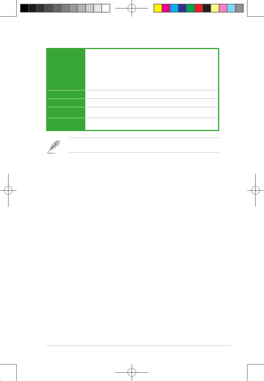
Package contents
Check your motherboard package for the following items.
Motherboard 1 x PRIME B560-PLUS motherboard
Cables 2 x SATA 6Gb/s cables
1 x M.2 Key E screw package
Miscellaneous
Application DVD 1 x Support DVD
Documentation 1 x User manual
1 x I/O Shield
1 x M.2 Rubber package
1 x M.2 SSD screw package
If any of the above items is damaged or missing, contact your retailer.
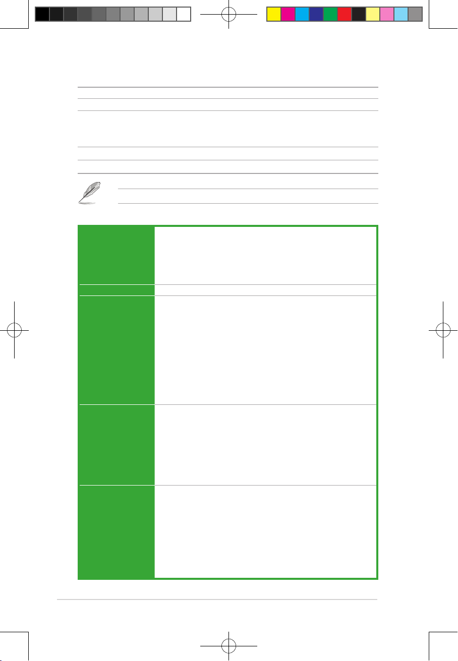
PRIME B560-PLUS specications summary
Intel® Socket LGA1200 for 11th Gen Intel® Core™ Processors & 10th Gen
Intel® Core™, Pentium® Gold and Celeron® Processors*
CPU
Chipset Intel® B560 Chipset
Memory
Graphics
Expansion Slots
vi
Supports Intel® 14 nm CPU
Supports Intel® Turbo Boost Technology 2.0 and Intel® Turbo Boost Max
Technology 3.0*
* Intel® Turbo Boost Max Technology 3.0 support depends on the CPU types.
4 x DIMM, Max. 128GB, DDR4 4600(OC)/4400(OC)/4266(OC
)/4000(OC)/3733(OC)/3600(OC)/3466(OC)/3333(OC)/3200(
OC)/2933/2800/2666/2400/2133 MHz Non-ECC, Un-buffered memory
Memory*
Dual Channel Memory Architecture
Supports Intel® Extreme Memory Prole (XMP)
ASUS OptiMem
* 10th Gen Intel® Core™ i7/i9 processors support 2933/2800/2666/2400/2133 natively,
others will run at the maximum transfer rate of DDR4 2666MHz.
* 11th Gen Intel® processors support 2933/2800/2666/2400/2133 natively.
* Refer to www.asus.com for the Memory QVL (Qualified Vendors Lists), and
memory frequency support depends on the CPU types.
1 x DisplayPort 1.2**
1 x D-Sub
1 x HDMI™ 1.4/2.0***
* Graphics specifications may vary between CPU types.
** Intel® 11th & 10th Gen processors support DisplayPort 1.4 with max. resolution of
4096 x 2304 @60Hz. Please refer to www.intel.com for any updates.
*** Only Intel® 11th Gen processors support HDMI™ 2.0 with max. resolution of
4K@60Hz, others will only support HDMI™ 1.4 with max. resolution of 4K@30Hz.
Please refer to www.intel.com for any updates.
th & 10th
Intel® 11
Gen Processors
1 x PCIe 4.0/3.0 x16 slot*
- Intel® 11th Gen processors support PCIe 4.0 x16 mode
- Intel® 10th Gen processors support PCIe 3.0 x16 mode
Intel® B560 Chipset
1 x PCIe 3.0 x16 slot (supports x4 mode)*
2 x PCIe 3.0 x1 slots
* Enable RST PCIe Storage Remapping for PCH attached PCIe slots to activate
Intel® Optane Memory.
(continued on the next page)
E177887_PRIME_B560-PLUS_UM.indd 6E177887_PRIME_B560-PLUS_UM.indd 6 2021/1/25 18:12:582021/1/25 18:12:58
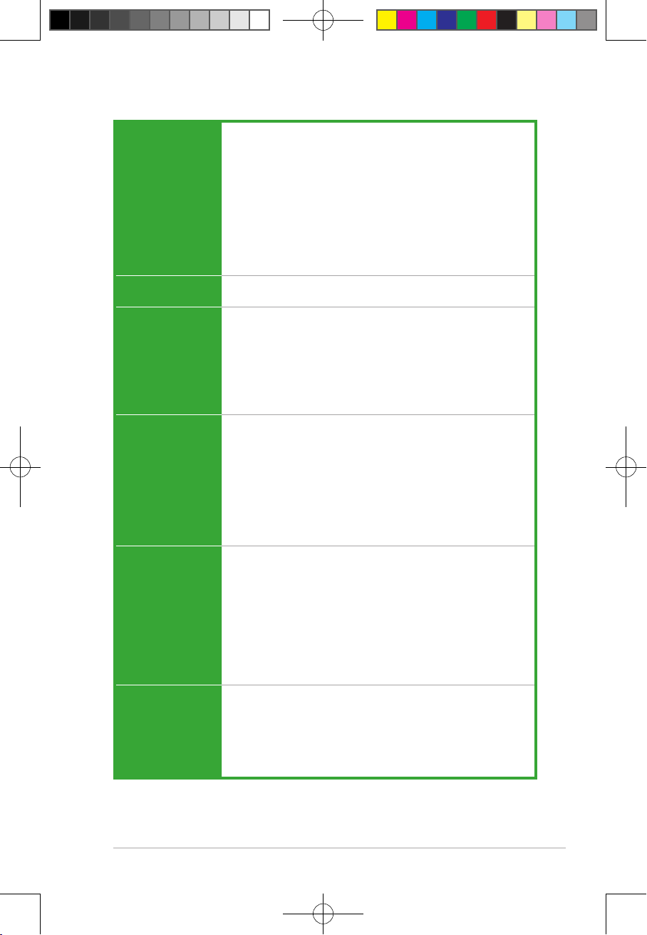
PRIME B560-PLUS specications summary
Total supports 2 x M.2 slots and 6 x SATA 6Gb/s ports
Intel® 11th Gen Processors
- M.2_1 slot (Key M) type 2242/2260/2280/22110 (supports PCIE 4.0 x 4 )
- Only Intel® 11th Gen processors support PCIe 4.0 x4 mode, this slot will be
Storage
Ethernet
USB
Audio
Back Panel I/O Ports
Internal I/O
Connectors
disabled for other CPUs
Intel® B560 Chipset
- M.2_2 slot (Key M) type 2242/2260/2280/22110 (supports PCIE 3.0 x 4 &
SATA modes)
- 6 x SATA 6Gb/s ports
* When a device in SATA mode is installed on the M.2_2 socket, the SATA6G_2
port cannot be used.
1 x Intel® I219-V 1Gb Ethernet
ASUS LANGuard
Rear USB (Total 7 ports)
2 x USB 3.2 Gen 2 ports (2 x Type-A)
1 x USB 3.2 Gen 1 port (1 x USB Type-C®)
4 x USB 2.0 ports (4 x Type-A)
Front USB (Total 6 ports)
1 x USB 3.2 Gen 1 header supports additional 2 USB 3.2 Gen 1 ports
2 x USB 2.0 headers support additional 4 USB 2.0 ports
Realtek ALC 897 7.1 Surround Sound High Denition Audio CODEC*
- Supports: Jack detection, Multi-streaming, Front Panel Jack-retasking
- Supports up to 24-Bit/192 kHz playback
Audio Features
- Audio Shielding
- Premium Japanese audio capacitors
- Dedicated audio PCB layers
* A chassis with an HD audio module in the front panel is required to support 7.1
Surround Sound audio output.
2 x USB 3.2 Gen 2 ports (2 x Type-A)
1 x USB 3.2 Gen 1 port (1 x USB Type-C® port)
4 x USB 2.0 ports (4 x Type-A)
1 x DisplayPort
1 x D-Sub port
1 x HDMI™ port
1 x Intel® I219-V 1Gb Ethernet port
3 x Audio jacks
1 x PS/2 Keyboard/Mouse combo port
Fan and Cooling related
1 x 4-pin CPU Fan header
3 x 4-pin Chassis Fan headers
Power related
1 x 24-pin Main Power connector
1 x 8-pin +12V Power connector
(continued on the next page)
vii
E177887_PRIME_B560-PLUS_UM.indd 7E177887_PRIME_B560-PLUS_UM.indd 7 2021/1/25 18:12:582021/1/25 18:12:58
PRIME B560-PLUS specications summary
Storage related
2 x M.2 slots (Key M)
6 x SATA 6Gb/s ports
USB
1 x USB 3.2 Gen 1 header supports additional 2 USB 3.2 Gen 1 ports
2 x USB 2.0 headers support additional 4 USB 2.0 ports
Miscellaneous
Internal I/O
Connectors
Special Features
Software
Features
2 x AURA Addressable Gen 2 headers
2 x AURA RGB headers
1 x Clear CMOS header
1 x COM Port header
1 x Front Panel Audio header (AAFP)
1 x M.2 slot (Key E)
1 x S/PDIF Out header
1 x SPI TPM header (14-1pin)
1 x 20-3pin System Panel header with Chassis intrude function
1 x Thunderbolt™ header
ASUS 5X PROTECTION III
- DIGI+ VRM
- LANGuard
- Overvoltage Protection
- SafeSlot Core+
- Stainless-Steel Back I/O
ASUS Q-Design
- Q-DIMM
- Q-Slot
ASUS Thermal Solution
- Flexible M.2 heatsink
- VRM heatsink design
ASUS EZ DIY
- Box Headers
AURA Sync
- AURA RGB headers
- AURA Addressable Gen 2 RGB headers
ASUS Exclusive Software
Armoury Crate
- AURA Creator
- AURA Sync
AI Suite 3
- Performance And Power Saving Utility
TurboV EVO
EPU
DIGI+ VRM
Fan Xpert 2+
- EZ update
ASUS CPU-Z
DAEMON Tools
(continued on the next page)
viii
E177887_PRIME_B560-PLUS_UM.indd 8E177887_PRIME_B560-PLUS_UM.indd 8 2021/1/25 18:12:582021/1/25 18:12:58
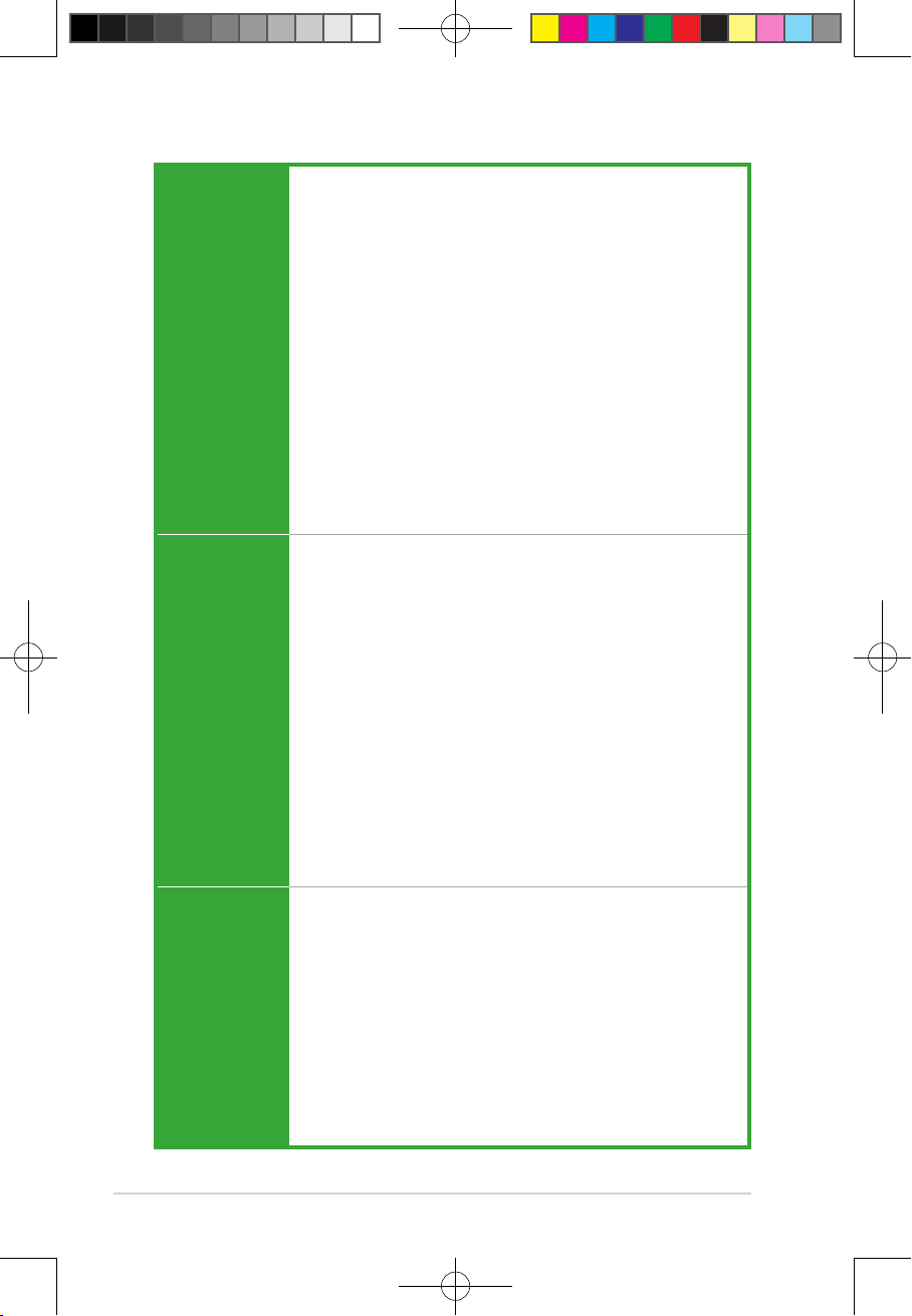
PRIME B560-PLUS specications summary
Norton Anti-virus software (Free Trial version)
WinRAR
Software
Features
BIOS 128 Mb Flash ROM, UEFI AMI BIOS
Manageability WOL by PME, PXE
Operating
System
Form Factor
UEFI BIOS
ASUS EZ DIY
- ASUS CrashFree BIOS 3
- ASUS EZ Flash 3
- ASUS UEFI BIOS EZ Mode
Windows® 10 64-bit
ATX Form Factor
12.0 inch x 9.2 inch (30.5 cm x 23.4 cm)
Specifications are subject to change without notice. Please refer to the ASUS website for
the latest specifications.
ix
E177887_PRIME_B560-PLUS_UM.indd 9E177887_PRIME_B560-PLUS_UM.indd 9 2021/1/25 18:12:592021/1/25 18:12:59
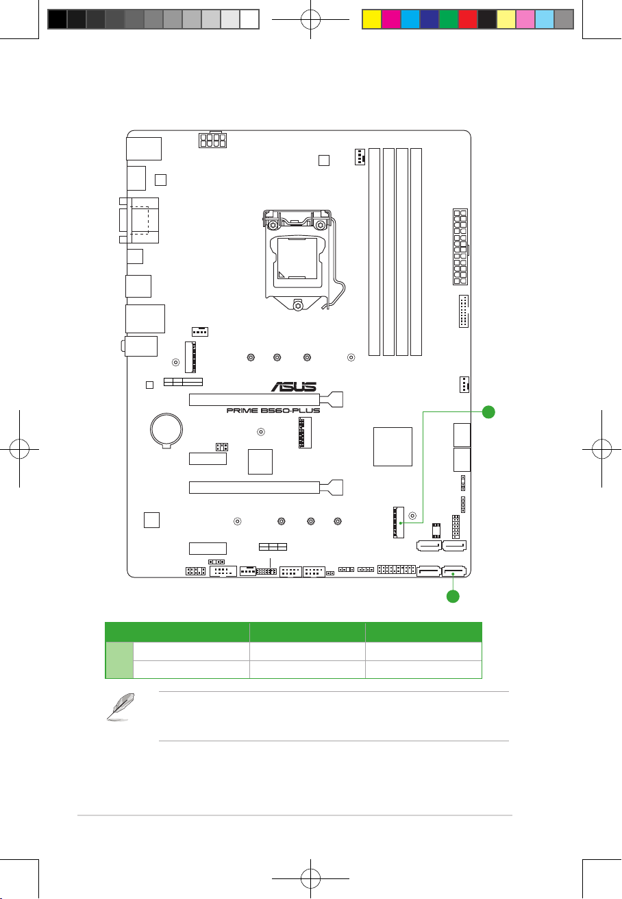
Connectors with shared bandwidth
KBMS_USB67
HDMI
DP
U32G1_C3
U32G2_12
LAN_USB45
AUDIO
Ethernet
Audio
Codec
ASM
1442K
VGA
M.2_1(SOCKET3)
PCIE SATA RAID ON CPU
4.0 X4 XX
BATTERY
ATX_12V
CHA_FAN1
M.2_1(SOCKET3)
PCIEX1_1
PCIEX1_2
AAFP
COM_DEBUG
SPDIF_OUT
COM
22110
PCIEX16_1
Super
PCIEX16_2
TB_HEADER
CHA_FAN2
I/O
M.2_2(SOCKET3)
LGA1200
2280 2260 2242
PCIE SATA IRST
3.0 X4 XV
USB_E12 USB_E34
DIGI+
VRM
CPU_FAN
EATXPWR
DDR4 DIMM_B1 (64bit, 288-pin module)
DDR4 DIMM_B2* (64bit, 288-pin module)
DDR4 DIMM_A1 (64bit, 288-pin module)
DDR4 DIMM_A2* (64bit, 288-pin module)
U32G1_1011
2280 2211022602242
CHA_FAN3
A
M.2(WIFI)
CLRTC
ADD_GEN 2_1
RGB_HEADER1
Intel
B560
M.2_2(SOCKET3)
PANEL
®
128Mb
BIOS
SATA6G_4 SATA6G_3
SATA6G_1 SATA6G_2
SATA6G_5 SATA6G_6
ADD_GEN 2_2
RGB_HEADER2
TPM
A
Conguration 1 2
M.2_2 PCIe x4 SATA
A
SATA6G_2 V -
• The M.2_2 slot shares bandwidth with the SATA6G_2 port.
• When a device in SATA mode is installed on the M.2 socket, the SATA6G_2 port
cannot be used.
x
E177887_PRIME_B560-PLUS_UM.indd 10E177887_PRIME_B560-PLUS_UM.indd 10 2021/1/25 18:12:592021/1/25 18:12:59
17
ASUS PRIME B560-PLUS
Chapter 1: Product Introduction
Product Introduction
1
1.1 Before you proceed
Take note of the following precautions before you install motherboard components or change
any motherboard settings.
• Unplug the power cord from the wall socket before touching any component.
• Before handling components, use a grounded wrist strap or touch a safely grounded
object or a metal object, such as the power supply case, to avoid damaging them due
to static electricity.
• Before you install or remove any component, ensure that the ATX power supply is
switched off or the power cord is detached from the power supply. Failure to do so
may cause severe damage to the motherboard, peripherals, or components.
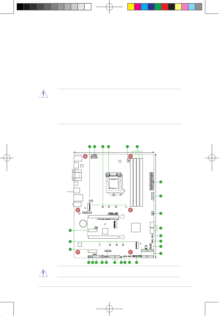
1.2 Motherboard overview
5 64 1 24
KBMS_USB67
HDMI
Place this
side towards
the rear of the
chassis
U32G2_12
LAN_USB45
AUDIO
3
6
3
DP
U32G1_C3
Ethernet
Audio
Codec
ASM
1442K
VGA
M.2_1(SOCKET3)
PCIE SATA RAID ON CPU
4.0 X4 XX
BATTERY
CHA_FAN1
PCIEX1_1
PCIEX1_2
AAFP
ATX_12V
M.2_1(SOCKET3)
COM_DEBUG
SPDIF_OUT
23.4cm(9.2in)
DIGI+
VRM
CPU_FAN
5
LGA1200
DDR4 DIMM_B1 (64bit, 288-pin module)
2280 2211022602242
PCIEX16_1
I/O
2280 2260 2242
M.2_2(SOCKET3)
PCIE SATA IRST
3.0 X4 XV
USB_E12 USB_E34
M.2(WIFI)
Super
PCIEX16_2
22110
TB_HEADER
CHA_FAN2
COM
Intel
B560
ADD_GEN 2_1
CLRTC
RGB_HEADER1
EATXPWR
DDR4 DIMM_B2* (64bit, 288-pin module)
DDR4 DIMM_A1 (64bit, 288-pin module)
DDR4 DIMM_A2* (64bit, 288-pin module)
U32G1_1011
CHA_FAN3
®
SATA6G_5 SATA6G_6
ADD_GEN 2_2
RGB_HEADER2
128Mb
TPM
BIOS
M.2_2(SOCKET3)
SATA6G_4 SATA6G_3
SATA6G_1 SATA6G_2
PANEL
8
30.5cm(12in)
4
7
10
11
16
7
171110129184131514
Unplug the power cord before installing or removing the motherboard. Failure to do so can
cause you physical injury and damage motherboard components.
1-1
E177887_PRIME_B560-PLUS_UM.indd 1E177887_PRIME_B560-PLUS_UM.indd 1 2021/1/25 18:12:592021/1/25 18:12:59
1.2.1 Layout contents
FAN PWM
FAN IN
FAN PWR
GND
FAN PWM
FAN IN
FAN PWR
GND
Chapter 1: Product Introduction
1. CPU socket
The motherboard comes with a LGA1200 socket designed for 11th Gen Intel® Core™
Processors & 10th Gen Intel® CoreTM, Pentium® Gold and Celeron® Processors.
For more details, refer to Central Processing Unit (CPU).
2. DDR4 DIMM slots
The motherboard comes with Dual Inline Memory Modules (DIMM) slots designed for DDR4
(Double Data Rate 4) memory modules.
For more details, refer to System memory.
3. Expansion slots
This motherboard supports two PCIe x16 graphics card and two PCIe 3.0 x1 network cards,
SCSI cards and other cards that comply with the PCI Express specication.
4. Fan headers
The Fan headers allow you to connect fans to cool the system.
5. Power connectors
These Power connectors allow you to connect your motherboard to a power supply. The
power supply plugs are designed to t in only one orientation. Find the proper orientation and
push down rmly until the power supply plugs are fully inserted.
Ensure to connect the 8-pin power plug.
• For a fully congured system, we recommend that you use a power supply unit
(PSU) that complies with ATX 12V Specication 2.0 (or later version) and provides a
minimum power of 350W.
• We recommend that you use a PSU with a higher power output when conguring a
system with more power-consuming devices. The system may become unstable or
may not boot up if the power is inadequate.
• If you are uncertain about the minimum power supply requirement for your system, we
recommend you to refer to online resources for Power Supply Wattage Calculator.
6. M.2 slots (Key M)
The M.2 slots allow you to install M.2 devices such as M.2 SSD modules.
1-2
E177887_PRIME_B560-PLUS_UM.indd 2E177887_PRIME_B560-PLUS_UM.indd 2 2021/1/25 18:12:592021/1/25 18:12:59

• Intel® 11th Gen processors:
ASUS PRIME B560-PLUS
- M.2_1 supports PCIe 4.0 x4 mode M Key design and type 2242/2260/2280/22110
PCIe storage devices.
Only Intel® 11th Gen processors support PCIe 4.0 x4 mode, this slot will be disabled
for other CPUs.
• Intel® B560 Chipset :
- M.2_2 supports PCIe 3.0 x4 and SATA modes M Key design and type
2242/2260/2280/22110 storage devices.
• When a device in SATA mode is installed on the M.2_2 socket, the SATA6G_2 port
cannot be used.
7. SATA 6Gb/s connectors
The SATA 6Gb/s connectors allow you to connect SATA devices such as optical disc drives
and hard disk drives via SATA cables.
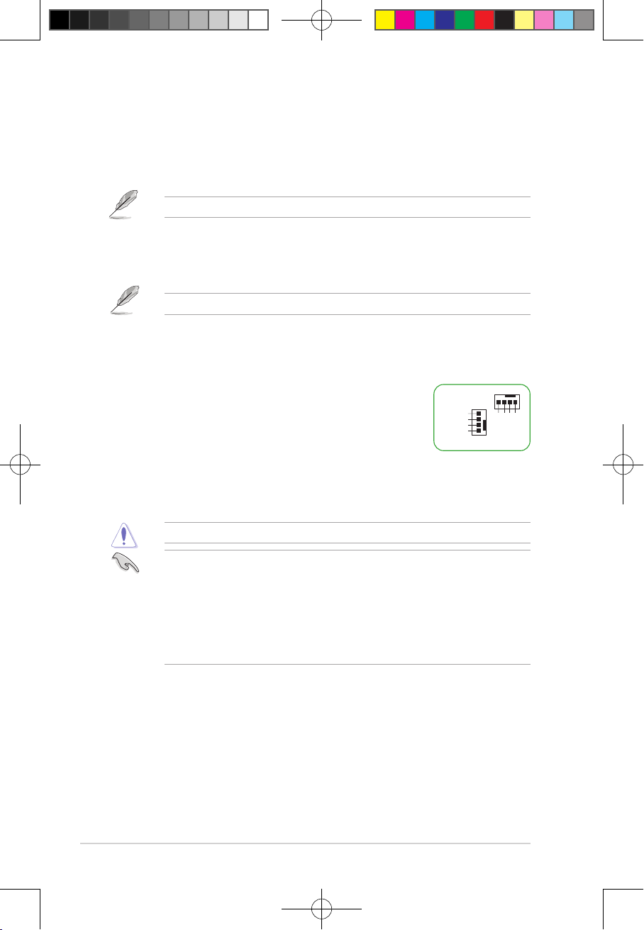
8. USB 3.2 Gen 1 header
The USB 3.2 Gen 1 header allows you to connect a USB 3.2 Gen
1 module for additional USB 3.2 Gen 1 ports. The USB 3.2 Gen 1
header provides data transfer speeds of up to 5 Gb/s.
The USB 3.2 Gen 1 module is purchased separately.
IntA_P2_SSRX-
IntA_P2_SSRX+
IntA_P2_SSTXIntA_P2_SSTX+
USB3+5V
IntA_P2_D-
IntA_P2_D+
PIN 1
USB3+5V
IntA_P1_SSRXIntA_P1_SSRX+
GND
IntA_P1_SSTX-
GND
IntA_P1_SSTX+
GND
IntA_P1_D-
GND
IntA_P1_D+
GND
9. USB 2.0 headers
The two USB 2.0 headers allow you to connect USB modules for additional four USB 2.0
ports. The USB 2.0 headers provide data transfer speeds of up to 480 Mb/s.
USB+5V
USB_P11-
USB_P11+
GND
DO NOT connect a 1394 cable to the USB connectors. Doing so will
NC
damage the motherboard!
PIN 1
The USB 2.0 module is purchased separately.
USB+5V
USB_P12-
GND
USB_P12+
10. Aura Addressable Gen 2 headers
The Addressable Gen 2 headers allow you to connect individually addressable RGB
WS2812B LED strips or WS2812B based LED strips.
The Addressable Gen 2 header supports WS2812B addressable RGB
LED strips (5V/Data/Ground), with a maximum power rating of 3A (5V),
and the addressable headers on this board can handle a combined
maximum of 500 LEDs.
ADD_GEN 2
Before you install or remove any component, ensure that the power supply is switched off
or the power cord is detached from the power supply. Failure to do so may cause severe
damage to the motherboard, peripherals, or components.
1-3
E177887_PRIME_B560-PLUS_UM.indd 3E177887_PRIME_B560-PLUS_UM.indd 3 2021/1/25 18:12:592021/1/25 18:12:59
• Actual lighting and color will vary with LED strip.
Chapter 1: Product Introduction
• If your LED strip does not light up, check if the addressable RGB LED strip is
connected in the correct orientation, and the 5V connector is aligned with the 5V
header on the motherboard.
• The addressable RGB LED strip will only light up when the system is powered on.
• The addressable RGB LED strip is purchased separately.
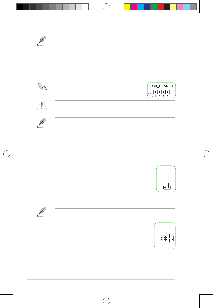
11. AURA RGB headers
The RGB headers allow you to connect RGB LED strips.
The RGB headers support 5050 RGB multi-color LED strips
(12V/G/R/B), with a maximum power rating of 3A (12V), and no
longer than 3m.
Before you install or remove any component, ensure that the ATX power supply is switched
off or the power cord is detached from the power supply. Failure to do so may cause
severe damage to the motherboard, peripherals, or components.
• Actual lighting and color will vary with LED strip.
• If your LED strip does not light up, check if the RGB LED extension cable and the
RGB LED strip are connected in the correct orientation, and the 12V connector is
aligned with the 12V header on the motherboard.
• The LED strip will only light up when the system is powered on.
• The LED strip is purchased separately.
12. Clear CMOS header
This header allows you to clear the CMOS RTC RAM data of the system setup information
such as date, time, and system passwords.
To erase the RTC RAM:
CLRTC
1. Turn OFF the computer and unplug the power cord.
+3V_BAT
2. Use a metal object such as a screwdriver to short the two pins.
3. Plug the power cord and turn ON the computer.
GND
PIN 1
4. Hold down the <Del> key during the boot process and enter BIOS setup to re-
enter data.
If the steps above do not help, remove the onboard battery and short the two pins again to
clear the CMOS RTC RAM data. After clearing the CMOS, reinstall the battery.
13. COM Port header
This header is for a serial (COM) port. Connect the serial port module cable to
COM
DTR
RXD
DSR
CTS
this header, then install the module to a slot opening at the back of the system
chassis.
1-4
PIN 1
DCD
TXD
GND
RTS
RI
E177887_PRIME_B560-PLUS_UM.indd 4E177887_PRIME_B560-PLUS_UM.indd 4 2021/1/25 18:12:592021/1/25 18:12:59

AAFP
AGNDNCSENSE1_RETUR
SENSE2_RETUR
PORT1 L
PORT1 R
PORT2 R
SENSE_SEND
PORT2 L
HD-audio-compliant
pin definition
14. Front panel audio header
TPM
PIN 1
T_SPI_MOSI
T_SPI_CLK
GND
F_BIOS_WP#_R
S_SPI_TPM_CS2#
S_SPI_TPM_IRQ#
F_SPI_HOLD#_R
T_SPI_MISO
F_SPI_CS0#_R
+3V_SPI
F2_SPI_CS1#_R
S_PLTRST#
VCCSPI
ASUS PRIME B560-PLUS
This header is for a chassis-mounted front panel audio I/O module that
supports HD audio standard. Connect one end of the front panel audio
I/O module cable to this header.
• We recommend that you connect a high-denition front panel
audio module to this header to avail of the motherboard’s highdenition audio capability.
• If you want to connect a high-denition front panel audio
module to this header, set the Front Panel Type item in the
BIOS setup to [HD Audio]. By default, this header is set to [HD
Audio].
15. S/PDIF Out header
SPDIF_OUT
This header is for an additional Sony/Philips Digital Interface (S/PDIF) port.
Connect the S/PDIF Out module cable to this header, then install the module to a
slot opening at the back of the system chassis.
16. SPI TPM header
This header supports a Trusted Platform Module (TPM) system with a Serial
Peripheral Interface (SPI), allowing you to securely store keys, digital
certicates, passwords, and data. A TPM system also helps enhance
network security, protects digital identities, and ensures platform integrity.
The SPI TPM module is purchased separately.
17. 20-3 pin System Panel header
This header supports several chassis-mounted functions.
• System power LED (2-pin +PWR_LED-)
This 2-pin header is for the system power LED. Connect the
chassis power LED cable to this header. The system power
LED lights up when you turn on the system power, and blinks
when the system is in sleep mode.
• Hard disk drive activity LED (2-pin +HDD_LED-)
This 2-pin header is for the HDD Activity LED. Connect the
HDD Activity LED cable to this header. The HDD LED lights up
or ashes when data is read from or written to the HDD.
• System warning speaker (4-pin SPEAKER)
This 4-pin header is for the chassis-mounted system warning speaker. The speaker
allows you to hear system beeps and warnings.
+5V
SPDIFOUT
GND
E177887_PRIME_B560-PLUS_UM.indd 5E177887_PRIME_B560-PLUS_UM.indd 5 2021/1/25 18:12:592021/1/25 18:12:59
1-5

• ATX power button/soft-off button (2-pin PWR_SW)
Chapter 1: Product Introduction
This header is for the system power button. Pressing the power button turns the
system on or puts the system in sleep or soft-off mode depending on the operating
system settings. Pressing the power switch for more than four seconds while the
system is ON turns the system OFF.
• Reset button (2-pin RESET)
This 2-pin header is for the chassis-mounted reset button for system reboot without
turning off the system power.
• Chassis intrusion header (2-pin CHASSIS)
This header is for a chassis-mounted intrusion detection sensor or switch. Connect one
end of the chassis intrusion sensor or switch cable to this header. The chassis intrusion
sensor or switch sends a high-level signal to this connector when a chassis component
is removed or replaced. The signal is then generated as a chassis intrusion event.
18. Thunderbolt™ header
The Thunderbolt™ header allows you to connect an add-on
Thunderbolt™ I/O card that supports Intel®’s Thunderbolt™
Technology, allowing you to connect Thunderbolt™-enabled
devices and DisplayPort-enabled devices to form a daisy
chain-configuration.
• The add-on Thunderbolt™ I/O card and Thunderbolt™
cables are purchased separately.
• Please visit the official website of your purchased
Thunderbolt™ card for more details on compatibility.
TB_HEADER
I2C_SCL
I2C_SDA
I2C_IRQ#
PIN 1
SLP_S3#
FORCE_PWR
TB_CIO_PLUG_EVENT
RTD3_POWER_EN
SLP_S5#
S_SLP_S0#_IDLE
PERST_N
WAKE#
GND
RTD3_SW
1-6
E177887_PRIME_B560-PLUS_UM.indd 6E177887_PRIME_B560-PLUS_UM.indd 6 2021/1/25 18:13:002021/1/25 18:13:00

1.2.2 Rear panel connectors
ASUS PRIME B560-PLUS
1
2
3
4 5
6
7
8
109
6 11
1. PS/2 keyboard/mouse combo port. This port is for a PS/2 mouse or keyboard.
2. Video Graphics Adapter (VGA) port. This 15-pin port is for a VGA monitor or other
VGA-compatible devices.
3. Ethernet port. This port allows Gigabit connection to a Local Area Network (LAN)
through a network hub. Refer to the table below for the Ethernet port LED indications.
Ethernet port LED indications
Activity Link LED Speed LED
Status Description Status Description
OFF No link OFF 10 Mbps connection
ORANGE Linked ORANGE 100 Mbps connection
BLINKING Data activity GREEN 1 Gbps connection
ACT/LINK
LED
SPEED
Ethernet port
LED
4. Line In port (light blue). This port connects the tape, CD, DVD player, or other audio
sources.
5. Line Out port (lime). This port connects a headphone or a speaker. In 4-channel,
5.1-channel, and 7.1-channel congurations, the function of this port becomes Front
Speaker Out.
6. USB 2.0 ports. These 4-pin Universal Serial Bus (USB) ports are for USB 2.0 devices.
7. HDMI™ port. This port is for a High-Denition Multimedia Interface (HDMI™) connector,
and is HDCP compliant allowing playback of HD DVD, Blu-ray, and other protected
content.
8. DisplayPort. This port is for a DisplayPort-compatible device.
9. USB 3.2 Gen 1 (Type-C®) port. This Universal Serial Bus (USB) port connects to a
USB 3.2 Gen 1 device.
10. USB 3.2 Gen 2 (up to 10Gbps) ports. These 9-pin Universal Serial Bus (USB) ports
connect to USB 3.2 Gen 2 devices.
1-7
E177887_PRIME_B560-PLUS_UM.indd 7E177887_PRIME_B560-PLUS_UM.indd 7 2021/1/25 18:13:002021/1/25 18:13:00

11. Microphone port (pink). This port connects a microphone.
Chapter 1: Product Introduction
Refer to the audio conguration table for the function of the audio ports in 2, 4, 5.1, or
7.1-channel conguration.
Audio 2, 4, 5.1 or 7.1-channel conguration
output.
Headset
2-channel
Line In Rear Speaker Out Rear Speaker Out Rear Speaker Out
4-channel 5.1-channel 7.1-channel
Side Speaker Out*/
Headphone
Mic In* / Side
Speaker Out
Port
Light Blue
(Rear panel)
Lime (Rear panel) Line Out Front Speaker Out Front Speaker Out Front Speaker Out
Pink (Rear panel) Mic In Mic In Bass/Center Bass/Center
Lime (Front panel) — — —
Pink (Front panel) — — —
* Multi-streaming is disabled by default, and the Lime (front panel) jack may be used as Side Speaker Out. If multi-
streaming is enabled, the Lime (front panel) jack will support headphone, and the Pink (front panel) jack will
support Side Speaker Out.
To congure a 7.1-channel audio output:
Use a chassis with HD audio module in the front panel to support a 7.1-channel audio
1-8
E177887_PRIME_B560-PLUS_UM.indd 8E177887_PRIME_B560-PLUS_UM.indd 8 2021/1/25 18:13:002021/1/25 18:13:00

1.3 Central Processing Unit (CPU)
ASUS PRIME B560-PLUS
This motherboard comes with a LGA1200 socket designed for 11th Gen
Intel® Core™ Processors & 10th Gen Intel® CoreTM, Pentium® Gold and
Celeron® Processors.
Unplug all power cables before installing the CPU.
• Ensure that you install the correct CPU designed for the LGA1200 socket only. DO
NOT install a CPU designed for LGA1150, LGA1151, LGA1155 and LGA1156 sockets
on the LGA1200 socket.
• Upon purchase of the motherboard, ensure that the PnP cap is on the socket and
the socket contacts are not bent. Contact your retailer immediately if the PnP cap
is missing, or if you see any damage to the PnP cap/socket contacts/motherboard
components.
• Keep the cap after installing the motherboard. ASUS will process Return Merchandise
Authorization (RMA) requests only if the motherboard comes with the cap on the
LGA1200 socket.
• The product warranty does not cover damage to the socket contacts resulting from
incorrect CPU installation/removal, or misplacement/loss/incorrect removal of the PnP
cap.
Installing the CPU
1
A
B
4
2
A
3
D
5
4
C
5
B
4
Apply the Thermal Interface Material to the CPU heatsink and CPU before you install the
heatsink and fan if necessary.
1-9
E177887_PRIME_B560-PLUS_UM.indd 9E177887_PRIME_B560-PLUS_UM.indd 9 2021/1/25 18:13:002021/1/25 18:13:00

1.4 System memory
Chapter 1: Product Introduction
This motherboard comes with four Double Data Rate 4 (DDR4) Dual Inline Memory Module
(DIMM) sockets. The gure illustrates the location of the DDR4 DIMM sockets:
DIMM_B1
DIMM_B2*
DIMM_A1
DIMM_A2*
• You may install varying memory sizes in Channel A and Channel B. The system
maps the total size of the lower-sized channel for the dual-channel conguration. Any
excess memory from the higher-sized channel is then mapped for single-channel
operation.
• A DDR4 memory module is notched differently from a DDR, DDR2, or DDR3 module.
DO NOT install a DDR, DDR2, or DDR3 memory module to the DDR4 slot.
• 11th Gen Intel® processors support 2933/2800/2666/2400/2133 natively.
• For 10th Gen Intel
®
processors, only Core™ i9/ i7 processors support
2933/2800/2666/2400/2133 natively, others will run at the maximum transfer rate of
DDR4 2666MHz.
• The default memory operation frequency is dependent on its Serial Presence Detect
(SPD), which is the standard way of accessing information from a memory module.
Under the default state, some memory modules for overclocking may operate at a
lower frequency than the vendor-marked value.
• For system stability, use a more efcient memory cooling system to support a full
memory load.
• Refer to www.asus.com for the latest Memory QVL (Qualied Vendors Lists),and
memory frequency support depends on the CPU types.
Recommended memory congurations
Channel Sockets
Channel A DIMM_A1 & DIMM_A2*
Channel B DIMM_B1 & DIMM_B2*
DIMM_B1
DIMM_B2*
DIMM_A2*DIMM_A2*
DIMM_B2*
DIMM_A1
DIMM_A2*
1-10
E177887_PRIME_B560-PLUS_UM.indd 10E177887_PRIME_B560-PLUS_UM.indd 10 2021/1/25 18:13:002021/1/25 18:13:00

Installing a DIMM
ASUS PRIME B560-PLUS
1
To remove a DIMM
B
2
A
A
A
B
1-11
E177887_PRIME_B560-PLUS_UM.indd 11E177887_PRIME_B560-PLUS_UM.indd 11 2021/1/25 18:13:002021/1/25 18:13:00

1.5 M.2 Installation
Chapter 1: Product Introduction
1
2
1
4
3
OPTIONAL
7
6
7
5
• Ensure to install the bundled M.2 rubber pad before installing your single sided M.2
storage device.
• DO NOT install the bundled M.2 rubber pads when installing a double-sided M.2
storage device. The rubber pad installed by default is compatible with double sided
M.2 storage devices.
• The diagrams in this section are for reference only.
• The M.2 device is purchased separately.
1-12
E177887_PRIME_B560-PLUS_UM.indd 12E177887_PRIME_B560-PLUS_UM.indd 12 2021/1/25 18:13:012021/1/25 18:13:01
BIOS Information
ASUS PRIME B560-PLUS
2
2.1 Knowing BIOS
The new ASUS UEFI BIOS is a Unied Extensible Interface that complies with UEFI
architecture, offering a user-friendly interface that goes beyond the traditional keyboard-
only BIOS controls to enable a more flexible and convenient mouse input. You can easily
navigate the new UEFI BIOS with the same smoothness as your operating system. The
term “BIOS” in this user manual refers to “UEFI BIOS” unless otherwise specied.
BIOS (Basic Input and Output System) stores system hardware settings such as storage
device conguration, overclocking settings, advanced power management, and boot
device conguration that are needed for system startup in the motherboard CMOS. In
normal circumstances, the default BIOS settings apply to most conditions to ensure
optimal performance. DO NOT change the default BIOS settings except in the following
circumstances:
• An error message appears on the screen during the system bootup and requests you
to run the BIOS Setup.
• You have installed a new system component that requires further BIOS settings or
update.
Inappropriate BIOS settings may result to instability or boot failure. We strongly
recommend that you change the BIOS settings only with the help of a trained service
personnel.
BIOS settings and options may vary due to different BIOS release versions. Please refer to
the latest BIOS version for settings and options.
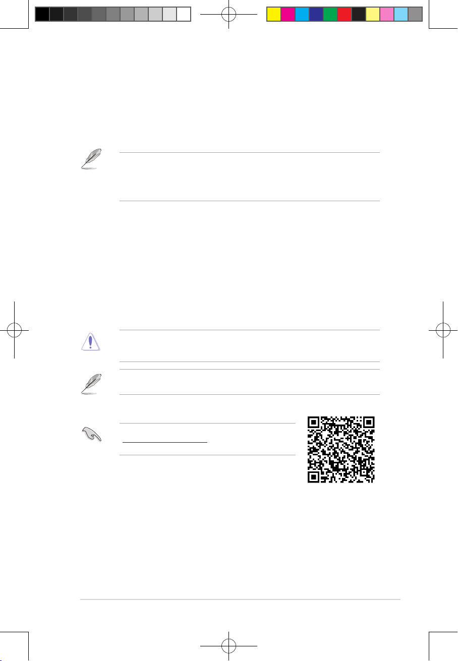
For more information on BIOS congurations, please refer to
https://www.asus.com/support, or download the BIOS manual
by scanning the QR code.
2-1
E177887_PRIME_B560-PLUS_UM.indd 1E177887_PRIME_B560-PLUS_UM.indd 1 2021/1/25 18:13:012021/1/25 18:13:01

2.2 BIOS Setup program
Chapter 2: BIOS Information
Use the BIOS Setup to update the BIOS or congure its parameters. The BIOS screens
include navigation keys and brief onscreen help to guide you in using the BIOS Setup
program.
Entering BIOS at startup
To enter BIOS Setup at startup, press <Delete> or <F2> during the Power-On Self Test
(POST). If you do not press <Delete> or <F2>, POST continues with its routines.
Entering BIOS Setup after POST
To enter BIOS Setup after POST:
• Press <Ctrl>+<Alt>+<Delete> simultaneously.
• Press the reset button on the system chassis.
• Press the power button to turn the system off then back on. Do this option only if you
failed to enter BIOS Setup using the rst two options.
After doing either of the three options, press <Delete> key to enter BIOS.
• Ensure that a USB mouse is connected to your motherboard if you want to use the
mouse to control the BIOS setup program.
• If the system becomes unstable after changing any BIOS setting, load the default
settings to ensure system compatibility and stability. Select the Load Optimized
Defaults item under the Exit menu or press hotkey <F5>.
• If the system fails to boot after changing any BIOS setting, try to clear the CMOS and
reset the motherboard to the default value.
• The BIOS setup program does not support Bluetooth devices.
BIOS menu screen
The BIOS Setup program can be used under two modes: EZ Mode and Advanced Mode.
You can change modes from Setup Mode in Boot menu or by pressing the <F7> hotkey.
2-2
E177887_PRIME_B560-PLUS_UM.indd 2E177887_PRIME_B560-PLUS_UM.indd 2 2021/1/25 18:13:012021/1/25 18:13:01

2.3 ASUS EZ Flash 3
ASUS PRIME B560-PLUS
The ASUS EZ Flash 3 feature allows you to update the BIOS without using an OS-based
utility.
Ensure to load the BIOS default settings to ensure system compatibility and stability. Select
the Load Optimized Defaults item under the Exit menu or press hotkey <F5>.
To update the BIOS:
• This function can support devices such as a USB flash disk with FAT 32/16 format and
single partition only.
• DO NOT shut down or reset the system while updating the BIOS to prevent system
boot failure!
1. Insert the USB flash disk that contains the latest BIOS le to the USB port.
2. Enter the Advanced Mode of the BIOS setup program. Go to the Tool menu to select
ASUS EZ Flash 3 Utility and press <Enter>.
3. Press the Left/Right arrow keys to switch to the Drive eld.
4. Press the Up/Down arrow keys to nd the USB flash disk that contains the latest BIOS,
and then press <Enter>.
5. Press the Left/Right arrow keys to switch to the Folder eld.
6. Press the Up/Down arrow keys to nd the BIOS le, and then press <Enter> to perform
the BIOS update process. Reboot the system when the update process is done.
2-3
E177887_PRIME_B560-PLUS_UM.indd 3E177887_PRIME_B560-PLUS_UM.indd 3 2021/1/25 18:13:012021/1/25 18:13:01

2.4 ASUS CrashFree BIOS 3
Chapter 2: BIOS Information
The ASUS CrashFree BIOS 3 utility is an auto recovery tool that allows you to restore the
BIOS file when it fails or gets corrupted during the updating process. You can restore a
corrupted BIOS file using a USB flash drive that contains the BIOS file.
Recovering the BIOS
1. Download the latest BIOS version for this motherboard from
https://www.asus.com/support/.
2. Rename the BIOS file as ASUS.CAP or PB560PS.CAP and copy the renamed BIOS
file to a USB flash drive.
3. Turn on the system.
4. Insert the USB flash drive containing the BIOS file to a USB port.
5. The utility automatically checks the devices for the BIOS file. When found, the utility
reads the BIOS file and enters ASUS EZ Flash 3 automatically.
6. The system requires you to enter BIOS Setup to recover the BIOS setting. To ensure
system compatibility and stability, we recommend that you press <F5> to load default
BIOS values.
DO NOT shut down or reset the system while updating the BIOS! Doing so can cause
system boot failure!
2-4
E177887_PRIME_B560-PLUS_UM.indd 4E177887_PRIME_B560-PLUS_UM.indd 4 2021/1/25 18:13:012021/1/25 18:13:01

Appendix
ASUS PRIME B560-PLUS
Notices
FCC Compliance Information
Responsible Party: Asus Computer International
Address: 48720 Kato Rd., Fremont, CA 94538, USA
Phone / Fax No: (510)739-3777 / (510)608-4555
This device complies with part 15 of the FCC Rules. Operation is subject to the following
two conditions: (1) This device may not cause harmful interference, and (2) this device must
accept any interference received, including interference that may cause undesired operation.
This equipment has been tested and found to comply with the limits for a Class B digital
device, pursuant to part 15 of the FCC Rules. These limits are designed to provide
reasonable protection against harmful interference in a residential installation. This equipment
generates, uses and can radiate radio frequency energy and, if not installed and used in
accordance with the instructions, may cause harmful interference to radio communications.
However, there is no guarantee that interference will not occur in a particular installation. If
this equipment does cause harmful interference to radio or television reception, which can be
determined by turning the equipment off and on, the user is encouraged to try to correct the
interference by one or more of the following measures:
- Reorient or relocate the receiving antenna.
- Increase the separation between the equipment and receiver.
- Connect the equipment into an outlet on a circuit different from that to which the receiver is
connected.
- Consult the dealer or an experienced radio/TV technician for help.
HDMI Compliance Statement
The terms HDMI, HDMI High-Definition Multimedia Interface, and the HDMI Logo are
trademarks or registered trademarks of HDMI Licensing Administrator, Inc.
A-1
E177887_PRIME_B560-PLUS_UM.indd 1E177887_PRIME_B560-PLUS_UM.indd 1 2021/1/25 18:13:012021/1/25 18:13:01

Compliance Statement of Innovation, Science and Economic
Appendices
Development Canada (ISED)
This device complies with Innovation, Science and Economic Development Canada licence
exempt RSS standard(s). Operation is subject to the following two conditions: (1) this device
may not cause interference, and (2) this device must accept any interference, including
interference that may cause undesired operation of the device.
CAN ICES-003(B)/NMB-003(B)
Déclaration de conformité de Innovation, Sciences et
Développement économique Canada (ISED)
Le présent appareil est conforme aux CNR d’Innovation, Sciences et Développement
économique Canada applicables aux appareils radio exempts de licence. L’exploitation est
autorisée aux deux conditions suivantes : (1) l’appareil ne doit pas produire de brouillage,
et (2) l’utilisateur de l’appareil doit accepter tout brouillage radioélectrique subi, même si le
brouillage est susceptible d’en compromettre le fonctionnement.
CAN ICES-003(B)/NMB-003(B)
VCCI: Japan Compliance Statement
Class B ITE
Japan JATE
本製品は電気通信事業者(移動通信会社、固定通信会社、インターネットプロバイダ等)の通信
回線(公衆無線LANを含む)に直接接続することができません。本製品をインターネットに接続す
る場合は、必ずルータ等を経由し接続してください。」等が考えられる。
KC: Korea Warning Statement
A-2
E177887_PRIME_B560-PLUS_UM.indd 2E177887_PRIME_B560-PLUS_UM.indd 2 2021/1/25 18:13:012021/1/25 18:13:01
Google™ License Terms
ASUS PRIME B560-PLUS
Copyright© 2021 Google Inc. All Rights Reserved.
Licensed under the Apache License, Version 2.0 (the “License”); you may not use this file
except in compliance with the License. You may obtain a copy of the License at:
http://www.apache.org/licenses/LICENSE-2.0
Unless required by applicable law or agreed to in writing, software distributed under the
License is distributed on an “AS IS” BASIS, WITHOUT WARRANTIES OR CONDITIONS
OF ANY KIND, either express or implied.
See the License for the specific language governing permissions and limitations under the
License.
Declaration of compliance for product environmental
regulation
ASUS follows the green design concept to design and manufacture our products, and
makes sure that each stage of the product life cycle of ASUS product is in line with global
environmental regulations. In addition, ASUS disclose the relevant information based on
regulation requirements.
Please refer to http://csr.asus.com/Compliance.htm for information disclosure based on
regulation requirements ASUS is complied with:
EU REACH and Article 33
Complying with the REACH (Registration, Evaluation, Authorisation, and Restriction of
Chemicals) regulatory framework, we published the chemical substances in our products at
ASUS REACH website at http://csr.asus.com/english/REACH.htm.
EU RoHS
This product complies with the EU RoHS Directive. For more details, see
http://csr.asus.com/english/article.aspx?id=35
India RoHS
This product complies with the “India E-Waste (Management) Rules, 2016” and prohibits
use of lead, mercury, hexavalent chromium, polybrominated biphenyls (PBBs) and
polybrominated diphenyl ethers (PBDEs) in concentrations exceeding 0.1% by weight in
homogenous materials and 0.01% by weight in homogenous materials for cadmium, except
for the exemptions listed in Schedule II of the Rule.
Vietnam RoHS
ASUS products sold in Vietnam, on or after September 23, 2011,meet the requirements of
the Vietnam Circular 30/2011/TT-BCT.
Các sản phẩm ASUS bán tại Việt Nam, vào ngày 23 tháng 9 năm2011 trở về sau, đều phải đáp ứng
các yêu cầu của Thông tư 30/2011/TT-BCT của Việt Nam.
Turkey RoHS
AEEE Yönetmeliğine Uygundur
A-3
E177887_PRIME_B560-PLUS_UM.indd 3E177887_PRIME_B560-PLUS_UM.indd 3 2021/1/25 18:13:012021/1/25 18:13:01

ASUS Recycling/Takeback Services
Appendices
ASUS recycling and takeback programs come from our commitment to the highest
standards for protecting our environment. We believe in providing solutions for you to
be able to responsibly recycle our products, batteries, other components as well as the
packaging materials. Please go to http://csr.asus.com/english/Takeback.htm for detailed
recycling information in different regions.
DO NOT throw the motherboard in municipal waste. This product has been designed to
enable proper reuse of parts and recycling. This symbol of the crossed out wheeled bin
indicates that the product (electrical and electronic equipment) should not be placed in
municipal waste. Check local regulations for disposal of electronic products.
DO NOT throw the mercury-containing button cell battery in municipal waste. This symbol
of the crossed out wheeled bin indicates that the battery should not be placed in municipal
waste.
Regional notice for California
WARNING
Cancer and Reproductive Harm -
www.P65Warnings.ca.gov
A-4
E177887_PRIME_B560-PLUS_UM.indd 4E177887_PRIME_B560-PLUS_UM.indd 4 2021/1/25 18:13:012021/1/25 18:13:01
English ASUSTeK Computer Inc. hereby declares that this device is in
ASUS PRIME B560-PLUS
compliance with the essential requirements and other relevant provisions of
related Directives. Full text of EU declaration of conformity is available at:
www.asus.com/support
Français AsusTek Computer Inc. déclare par la présente que cet appareil est
conforme aux critères essentiels et autres clauses pertinentes des directives
concernées. La déclaration de conformité de l’UE peut être téléchargée à
partir du site Internet suivant : www.asus.com/support
Deutsch ASUSTeK Computer Inc. erklärt hiermit, dass dieses Gerät mit
den wesentlichen Anforderungen und anderen relevanten Bestimmungen
der zugehörigen Richtlinien übereinstimmt. Der gesamte Text der EUKonformitätserklärung ist verfügbar unter: www.asus.com/support
Italiano ASUSTeK Computer Inc. con la presente dichiara che questo
dispositivo è conforme ai requisiti essenziali e alle altre disposizioni
pertinenti con le direttive correlate. Il testo completo della dichiarazione di
conformità UE è disponibile all’indirizzo: www.asus.com/support
Русский Компания ASUS заявляет, что это устройство соответствует
основным требованиям и другим соответствующим условиям
соответствующих директив. Подробную информацию, пожалуйста,
смотрите на www.asus.com/support
Български С настоящото ASUSTeK Computer Inc. декларира, че това
устройство е в съответствие със съществените изисквания и другите
приложими постановления на свързаните директиви. Пълният текст на
декларацията за съответствие на ЕС е достъпна на адрес:
www.asus.com/support
Hrvatski ASUSTeK Computer Inc. ovim izjavljuje da je ovaj uređaj sukladan
s bitnim zahtjevima i ostalim odgovarajućim odredbama vezanih direktiva.
Cijeli tekst EU izjave o sukladnosti dostupan je na: www.asus.com/support
Čeština Společnost ASUSTeK Computer Inc. tímto prohlašuje, že
toto zařízení splňuje základní požadavky a další příslušná ustanovení
souvisejících směrnic. Plné znění prohlášení o shodě EU je k dispozici na
adrese: www.asus.com/support
Dansk ASUSTeK Computer Inc. erklærer hermed, at denne enhed er i
overensstemmelse med hovedkravene og andre relevante bestemmelser i
de relaterede direktiver. Hele EU-overensstemmelseserklæringen kan findes
på: www.asus.com/support
Nederlands ASUSTeK Computer Inc. verklaart hierbij dat dit apparaat
voldoet aan de essentiële vereisten en andere relevante bepalingen van
de verwante richtlijnen. De volledige tekst van de EU-verklaring van
conformiteit is beschikbaar op: www.asus.com/support
Eesti Käesolevaga kinnitab ASUSTeK Computer Inc, et see seade vastab
asjakohaste direktiivide oluliste nõuetele ja teistele asjassepuutuvatele
sätetele. EL vastavusdeklaratsiooni täielik tekst on saadaval järgmisel
aadressil: www.asus.com/support
Suomi ASUSTeK Computer Inc. ilmoittaa täten, että tämä laite on
asiaankuuluvien direktiivien olennaisten vaatimusten ja muiden tätä
koskevien säädösten mukainen. EU-yhdenmukaisuusilmoituksen koko teksti
on luettavissa osoitteessa: www.asus.com/support
Ελληνικά Με το παρόν, η AsusTek Computer Inc. δηλώνει ότι αυτή
η συσκευή συμμορφώνεται με τις θεμελιώδεις απαιτήσεις και άλλες
σχετικές διατάξεις των Οδηγιών της ΕΕ. Το πλήρες κείμενο της δήλωσης
συμβατότητας είναι διαθέσιμο στη διεύθυνση: www.asus.com/support
Magyar Az ASUSTeK Computer Inc. ezennel kijelenti, hogy ez az eszköz
megfelel a kapcsolódó Irányelvek lényeges követelményeinek és egyéb
vonatkozó rendelkezéseinek. Az EU megfelelőségi nyilatkozat teljes szövege
innen letölthető: www.asus.com/support
Latviski ASUSTeK Computer Inc. ar šo paziņo, ka šī ierīce atbilst saistīto
Direktīvu būtiskajām prasībām un citiem citiem saistošajiem nosacījumiem.
Pilns ES atbilstības paziņojuma teksts pieejams šeit: www.asus.com/support
Lietuvių „ASUSTeK Computer Inc.“ šiuo tvirtina, kad šis įrenginys atitinka
pagrindinius reikalavimus ir kitas svarbias susijusių direktyvų nuostatas. Visą
ES atitikties deklaracijos tekstą galima rasti: www.asus.com/support
Norsk ASUSTeK Computer Inc. erklærer herved at denne enheten er i
samsvar med hovedsaklige krav og andre relevante forskrifter i relaterte
direktiver. Fullstendig tekst for EU-samsvarserklæringen finnes på:
www.asus.com/support
Polski Firma ASUSTeK Computer Inc. niniejszym oświadcza, że
urządzenie to jest zgodne z zasadniczymi wymogami i innymi właściwymi
postanowieniami powiązanych dyrektyw. Pełny tekst deklaracji zgodności
UE jest dostępny pod adresem: www.asus.com/support
Português A ASUSTeK Computer Inc. declara que este dispositivo está em
conformidade com os requisitos essenciais e outras disposições relevantes
das Diretivas relacionadas. Texto integral da declaração da UE disponível em:
www.asus.com/support
Română ASUSTeK Computer Inc. declară că acest dispozitiv se conformează
cerinţelor esenţiale şi altor prevederi relevante ale directivelor conexe. Textul
complet al declaraţiei de conformitate a Uniunii Europene se găseşte la:
www.asus.com/support
Srpski ASUSTeK Computer Inc. ovim izjavljuje da je ovaj uređaj u saglasnosti
sa osnovnim zahtevima i drugim relevantnim odredbama povezanih
Direktiva. Pun tekst EU deklaracije o usaglašenosti je dostupan da adresi:
www.asus.com/support
Slovensky Spoločnosť ASUSTeK Computer Inc. týmto vyhlasuje, že toto
zariadenie vyhovuje základným požiadavkám a ostatým príslušným
ustanoveniam príslušných smerníc. Celý text vyhlásenia o zhode pre štáty EÚ
je dostupný na adrese: www.asus.com/support
Slovenščina ASUSTeK Computer Inc. izjavlja, da je ta naprava skladna z
bistvenimi zahtevami in drugimi ustreznimi določbami povezanih direktiv.
Celotno besedilo EU-izjave o skladnosti je na voljo na spletnem mestu:
www.asus.com/support
Español Por la presente, ASUSTeK Computer Inc. declara que este dispositivo
cumple los requisitos básicos y otras disposiciones pertinentes de las
directivas relacionadas. El texto completo de la declaración de la UE de
conformidad está disponible en: www.asus.com/support
Svenska ASUSTeK Computer Inc. förklarar härmed att denna
enhet överensstämmer med de grundläggande kraven och andra
relevanta föreskrifter i relaterade direktiv. Fulltext av EU-försäkran om
överensstämmelse finns på: www.asus.com/support
Українська ASUSTeK Computer Inc. заявляє, що цей пристрій відповідає
основним вимогам та іншим відповідним положенням відповідних
Директив. Повний текст декларації відповідності стандартам ЄС
доступний на: www.asus.com/support
Türk çe AsusTek Computer Inc., bu aygıtın temel gereksinimlerle ve ilişkili
Yönergelerin diğer ilgili koşullarıyla uyumlu olduğunu beyan eder. AB
uygunluk bildiriminin tam metni şu adreste bulunabilir:
www.asus.com/support
Bosanski ASUSTeK Computer Inc. ovim izjavljuje da je ovaj uređaj usklađen
sa bitnim zahtjevima i ostalim odgovarajućim odredbama vezanih direktiva.
Cijeli tekst EU izjave o usklađenosti dostupan je na: www.asus.com/support
A-5
E177887_PRIME_B560-PLUS_UM.indd 5E177887_PRIME_B560-PLUS_UM.indd 5 2021/1/25 18:13:012021/1/25 18:13:01

Warranty
Appendices
EN: ASUS Guarantee Information
• ASUS offers a voluntary manufacturer’s Commercial Guarantee.
• ASUS reserves the right to interpret the provisions of the ASUS
Commercial Guarantee.
• This ASUS Commercial Guarantee is provided independently and
in addition to the statutory Legal Guarantee and in no way affects
or limits the rights under the Legal Guarantee.
For all the guarantee information, please visit
https://www.asus.com/support.
F: Garantie ASUS
• ASUS fournit une garantie commerciale en tant que garantie
volontaire du fabricant.
• ASUS se réserve le droit d'interpréter et de clarifier les
informations relatives à la garantie commerciale ASUS.
• Cette garantie commerciale ASUS est fournie indépendamment
et parallèlement à la garantie légale, elle n'affecte ou ne limite
d'aucune façon les droits acquis par la garantie légale.
Pour plus d'informations sur la garantie, consultez le site
https://www.asus.com/fr/support/.
G: ASUS Garantieinformationen
• ASUS bietet eine freiwillige Warengarantie des Herstellers an.
• ASUS behält sich das Recht zur Auslegung der Bestimmungen in
der ASUS Warengarantie vor.
• Diese ASUS Warengarantie wird unabhängig und zusätzlich zur
rechtmäßigen gesetzlichen Garantie gewährt und beeinträchtigt
oder beschränkt in keiner Weise die Rechte aus der gesetzlichen
Garantie.
Die vollständigen Garantieinformationen finden Sie unter
https://www.asus.com/de/support/.
I: Informativa sulla Garanzia ASUS
• ASUS offre una Garanzia Commerciale volontaria del produttore.
• ASUS si riserva il diritto di interpretare le disposizioni della
Garanzia Commerciale ASUS.
• La presente Garanzia Commerciale ASUS viene fornita in modo
indipendente e in aggiunta alla Garanzia Legale prevista per
legge e non pregiudica o limita in alcun modo i diritti previsti dalla
Garanzia Legale.
Per tutte le informazioni sulla garanzia, visitare
https://www.asus.com/it/support.
R: Информация о гарантии ASUS
• ASUS предлагает добровольную гарантию от производителя.
• ASUS оставляет за собой право интерпретирование положений
гарантии ASUS.
• Настоящая гарантия ASUS никоим образом не ограничивает Ваши
права, предусмотренные локальным законодательством.
Для получения полной информации о гарантии посетите
https://www.asus.com/ru/support/.
DA: ASUS garantioplysninger
• ASUS tilbyder en valgfri handelsmæssig garanti.
• ASUS forbeholder sig retten til at fortolke bestemmelserne i ASUS’
handelsmæssige garanti.
• Denne handelsmæssige garanti fra ASUS tilbydes uafhængigt,
som en tilføjelse til den lovbestemte juridiske garanti og den
påvirker eller begrænser på ingen måde rettighederne i den
juridiske garanti.
Alle garantioplysningerne kan findes på
https://www.asus.com/dk/support/.
BG: Информация за гаранцията от ASUS
• ASUS предлага доброволна търговска гаранция от производителя.
• ASUS си запазва правото да тълкува условията на търговската
гаранция на ASUS.
• Тази търговска гаранция на ASUS се предлага независимо от
и в допълнение на законовата гаранция. Тя по никакъв начин
не оказва влияние върху правата на потребителя в законовата
гаранция и по никакъв начин не ги ограничава.
За цялостна информация относно гаранцията, моля, посетете
https://www.asus.com/support.
CZ: Informace o záruce společnosti ASUS
• Společnost ASUS nabízí dobrovolnou komerční záruku výrobce.
• Společnost ASUS si vyhrazuje právo vykládat ustanovení
komerční záruky společnosti ASUS.
• Tato komerční záruka společnosti ASUS je poskytována nezávisle
a jako doplněk zákonné záruky a žádným způsobem neovlivňuje
ani neomezuje práva vyplývající ze zákonné záruky.
Všechny informace o záruce najdete na adrese
https://www.asus.com/cz/support/.
CR: Informacije o ASUS jamstvu
• ASUS dragovoljno nudi komercijalno proizvođačko jamstvo.
• ASUS zadržava prava na tumačenje odredbi ASUS komercijalnog
jamstva.
• Ovo ASUS komercijalno jamstvo daje se neovisno i kao dodatak
zakonskom jamstvu i ni na koji način ne ograničuje prava iz okvira
zakonskog jamstva.
Sve informacije o jamstvu potražite na
https://www.asus.com/support.
DU: ASUS-garantie-informatie
• SUS biedt een vrijwillige commerciële garantie van de fabrikant.
• ASUS behoudt zich het recht voor om de bepalingen van de
commerciële garantie van ASUS uit te leggen.
• Deze commerciële garantie van ASUS wordt onafhankelijk en
als aanvulling op de statutaire Wettelijke garantie geboden en
beïnvloedt of beperkt in geen geval de rechten onder de wettelijke
garantie.
Voor alle informatie over de garantie, gaat u naar
https://www.asus.com/nl/support/.
EE: Teave ASUS-e garantii kohta
• ASUS pakub vabatahtlikku tasulist tootjagarantiid.
• ASUS jätab endale õiguse tõlgendada ASUS-e tasulise garantii
tingimusi.
• See ASUS-e tasuline garantii on sõltumatu lisagarantii seadusega
kehtestatud garantiile ega mõjuta mingil määral seadusega
kehtestatud garantiid ning seadusega kehtestatud garantii
piiranguid.
Vaadake garantiiga seotud teavet veebisaidilt
https://www.asus.com/ee/.
GK: Πληροφορίες εγγύησης ASUS
• Η ASUS προσφέρει μια εθελοντική Εμπορική εγγύηση κατασκευαστή.
• Η ASUS διατηρεί το δικαίωμα ερμηνείας των διατάξεων της Εμπορικής
εγγύησης ASUS.
• Αυτή η Εμπορική εγγύηση ASUS παρέχεται ανεξάρτητα και
επιπροσθέτως της θεσμικής Νομικής εγγύησης και σε καμία περίπτωση
δεν επηρεάζει ή περιορίζει τα δικαιώματα βάσει της Νομικής εγγύησης.
Για όλες τις πληροφορίες εγγύησης, επισκεφθείτε τη διεύθυνση
https://www.asus.com/gr-el/.
HUG: ASUS garanciális információk
• Az ASUS önkéntes gyártói kereskedelmi garanciát kínál.
• Az ASUS fenntartja magának a jogot, hogy értelmezze az ASUS
kereskedelmi garanciára vonatkozó rendelkezéseket.
• Ezt a kereskedelmi garanciát az ASUS függetlenül és a törvényes
garancia mellett nyújtja és semmilyen módon nem befolyásolja,
vagy korlátozza a jogi garancia nyújtotta jogokat.
A garanciára vonatkozó teljes körű információkért látogasson el a
https://www.asus.com/hu/support/ oldalra.
LV: ASUS garantijas informācija
• ASUS piedāvā brīvprātīgu ražotāja komerciālo garantiju.
• ASUS patur tiesības interpretēt ASUS komerciālās garantijas
noteikumus.
• Šī ASUS komerciālā garantija tiek piedāvāta neatkarīgi un
papildus likumā noteiktajai juridiskajai garantijai, un tā nekādi
neietekmē vai neierobežo juridiskajā garantijā noteiktās tiesības.
Lai iegūtu informāciju par garantiju, apmeklējiet vietni
https://www.asus.com/lv/.
LT: Informacija apie ASUS garantiją
• ASUS siūlo savanorišką komercinę gamintojo garantiją.
• ASUS pasilieka teisę savo nuožiūra aiškinti šios komercinės ASUS
garantijos nuostatas.
• Ši komercinė ASUS garantija suteikiama nepriklausoma, be
įstatyminės teisinės garantijos, ir jokiu būdu nepaveikia ar
neapriboja teisinės garantijos suteikiamų teisių.
Norėdami gauti visą informaciją apie garantiją, apsilankykite
https://www.asus.com/lt/.
PL: Informacje o gwarancji firmy ASUS
• Firma ASUS oferuje dobrowolną gwarancję handlową producenta.
• Firma ASUS zastrzega sobie prawo do interpretacji warunków
gwarancji handlowej firmy ASUS.
• Niniejsza gwarancja handlowa firmy ASUS jest udzielana
niezależnie, jako dodatek do wymaganej ustawowo gwarancji
prawnej i w żaden sposób nie wpływa na prawa przysługujące na
mocy gwarancji prawnej ani ich nie ogranicza.
Wszelkie informacje na temat gwarancji można znaleźć na stronie
https://www.asus.com/pl/support.
A-6
E177887_PRIME_B560-PLUS_UM.indd 6E177887_PRIME_B560-PLUS_UM.indd 6 2021/1/25 18:13:022021/1/25 18:13:02

PG: Informações de Garantia ASUS
ASUS PRIME B560-PLUS
• A ASUS oferece uma Garantia Comercial voluntária do fabricante.
• A ASUS reserva o direito de interpretar as disposições da
Garantia Comercial da ASUS.
• Esta Garantia Comercial da ASUS é fornecida de forma
independente além da Garantia Legal estatutária e não afeta nem
limita de qualquer forma os direitos estabelecidos na Garantia
Legal.
Para consultar todas as informações sobre a garantia, visite
https://www.asus.com/pt/support/.
RO: Informații despre garanția ASUS
• ASUS oferă o garanție comercială voluntară a producătorului.
• ASUS își rezervă dreptul de a interpreta prevederile garanției
comerciale ASUS.
• Această garanție comercială ASUS este oferită independent și în plus
față de garanția obligatorie legal și nu afectează sau limitează în niciun
fel drepturile acordate conform garanției legale.
Pentru toate informațiile legate de garanție, vizitați
https://www.asus.com/ro/support.
SL: Informacije o garanciji ASUS
• ASUS ponuja prostovoljno tržno garancijo proizvajalca.
• ASUS si pridržuje pravico do razlage določb tržne garancije
družbe ASUS.
• Ta tržna garancija družbe ASUS je na voljo neodvisno in kot
dodatek zakonsko predpisani pravni garanciji ter na noben način
ne vpliva na pravice, ki jih zagotavlja pravna garancija, oziroma jih
omejuje.
Vse informacije o garanciji najdete na spletnem mestu
https://www.asus.com/support.
SK: Informácie o záruke ASUS
• ASUS ponúka dobrovoľnú obchodnú záruku výrobcu.
• ASUS si vyhradzuje právo interpretovať ustanovenia obchodnej
záruky ASUS.
• Táto obchodná záruka ASUS je poskytnutá nezávisle a navyše
k zákonnej záruke a v žiadnom prípade neovplyvňuje ani
neobmedzuje tieto práva podľa tejto zákonnej záruky.
Všetky ďalšie informácie o záruke nájdete na
https://www.asus.com/sk/support.
ES: Información de garantía de ASUS
• ASUS ofrece una garantía comercial voluntaria del fabricante.
• ASUS se reserva el derecho de interpretar las disposiciones de
esta garantía comercial de ASUS.
• Esta garantía comercial de ASUS se proporciona de forma
independiente y adicional a la garantía estatutaria y de ninguna
manera afecta a los derechos bajo la garantía legal ni los limita.
Para obtener toda la información sobre la garantía, visite
https://www.asus.com/ES/support/.
TR: ASUS Garanti Bilgileri
• ASUS, gönüllü olarak üretici Ticari Garantisi sunar.
• ASUS, ASUS Ticari Garantisinin hükümlerini yorumlama hakkını
saklı tutar.
• Bu ASUS Ticari Garantisi, bağımsız olarak ve hukuki Yasal
Garanti’ye ek olarak sağlanır ve hiçbir şekilde Yasal Garanti
kapsamındaki hakları etkilemez veya sınırlandırmaz.
Tüm garanti bilgileri için lütfen https://www.asus.com/tr/support adresini
ziyaret edin.
FI: ASUS-takuutiedot
• ASUS tarjoaa vapaaehtoisen valmistajan kaupallisen takuun.
• ASUS pidättää oikeuden tulkita ASUS-kaupallisen takuun ehdot.
• Tämä ASUS-kaupallinen takuu tarjotaan itsenäisesti lakisääteisen
oikeudellisen takuun lisäksi eikä se vaikuta millään tavoin laillisen
takuun oikeuksiin tai rajoita niitä.
Saadaksesi kaikki takuutiedot, siirry osoitteeseen
https://www.asus.com/fi/support.
NW: Informasjon om ASUS-garanti
• ASUS tilbyr som produsent en frivillig kommersiell garanti.
• ASUS forbeholder seg retten til å tolke bestemmelsene i ASUS sin
kommersielle garanti.
• ASUS sin kommersielle garanti gis uavhengig og i tillegg til den
lovbestemte juridiske garantien, og verken påvirker eller begrenser
rettighetene under den juridiske garantien på noen måte.
Du finner fullstendig informasjon om garanti på
https://www.asus.com/no/support/.
SB: Informacije o ASUS garanciji
• ASUS nudi dobrovoljnu proizvođačku komercijalnu garanciju.
• ASUS zadržava pravo da tumači odredbe svoje ASUS
komercijalne garancije.
• Ova ASUS komercijalna garancija daje se nezavisno, kao dodatak
zakonskoj pravnoj garanciji, i ni ka koji način ne utiče na i ne
ograničava prava data pravnom garancijom.
Za sve informacije o garanciji, posetite
https://www.asus.com/support/.
SW: ASUS garantiinformation
• ASUS erbjuder en frivillig kommersiell tillverkningsgaranti.
• ASUS förbehåller sig rätten att tolka bestämmelserna i ASUS
kommersiella garanti.
• Denna kommersiella garanti från ASUS tillhandahålles separat
och som tillägg till den lagstadgade garantin, och påverkar eller
begränsar på intet sätts rättigheterna under den lagstadgade
garantin.
För all garantiinformation, besök https://www.asus.com/se/support/.
UA: Інформація про Гарантію ASUS
• ASUS пропонує добровільну Комерційну Гарантію виробника.
• ASUS застерігає за собою право тлумачити положення Комерційної
Гарантії ASUS
• Цю Комерційну Гарантію надано незалежно і на додаток до
обов’язкової Законної Гарантії; вона жодним чином не впливає на
права за Законною Гарантією і не обмежує їх.
Всю інформацію про гарантію подано тут:
https://www.asus.com/ua/support.
MX: Garantía y Soporte
Esta Garantía aplica en el país de compra. Usted acepta que en esta
garantía:
• Los procedimientos de servicio pueden variar en función del país.
• Algunos servicios y/o piezas de reemplazo pudieran no estar
disponibles en todos los países.
• Algunos países pueden tener tarifas y restricciones que se
apliquen en el momento de realizar el servicio, visite el sitio de
soporte de ASUS en https://www.asus.com/mx/support/ para ver
más detalles.
• Si tiene alguna queja o necesidad de un centro de reparación local
o el periodo de garantía del producto ASUS, por favor visite el sitio
de Soporte de ASUS en https://www.asus.com/mx/support/ para
mayores detalles.
Información de contacto ASUS
Esta garantía está respaldada por:
ASUSTeK Computer Inc.
Centro de Atención ASUS +52 (55) 1946-3663
BP: Informações de garantia ASUS
Esta garantia aplica-se ao período definido pela garantia legal (90
dias) mais o período de garantia comercial oferecido pela ASUS.
Por exemplo: 12M significa 12 meses de garantia no total (3 meses
de garantia legal mais 9 meses de garantia contratual), 24 meses
significa 24 meses de garantia no total (3 meses de garantia legal
mais 21 meses de garantia contratual) e 36 meses significa 36 meses
de garantia no total (3 meses de garantia legal e 33 de garantia
contratual) a contar da data da garantia declarada (Data de Início
da Garantia).
Para todas as informações de garantia, visite
https://www.asus.com/br/support/.
A-7
E177887_PRIME_B560-PLUS_UM.indd 7E177887_PRIME_B560-PLUS_UM.indd 7 2021/1/25 18:13:022021/1/25 18:13:02

ASUS contact information
Appendices
ASUSTeK COMPUTER INC.
Address 1F., No. 15, Lide Rd., Beitou Dist., Taipei City 112, Taiwan
Telephone +886-2-2894-3447
Fax +886-2-2890-7798
Web site https://www.asus.com
Technical Support
Telephone +86-21-38429911
Online support https://qr.asus.com/techserv
ASUS COMPUTER INTERNATIONAL (America)
Address 48720 Kato Rd., Fremont, CA 94538, USA
Telephone +1-510-739-3777
Fax +1-510-608-4555
Web site https://www.asus.com/us/
Technical Support
Support fax +1-812-284-0883
Telephone +1-812-282-2787
Online support https://qr.asus.com/techserv
ASUS COMPUTER GmbH (Germany and Austria)
Address Harkortstrasse 21-23, 40880 Ratingen, Germany
Web site https://www.asus.com/de
Online contact https://www.asus.com/support/Product/ContactUs/
Services/questionform/?lang=de-de
Technical Support
Telephone (DE) +49-2102-5789557
Telephone (AT) +43-1360-2775461
Online support https://www.asus.com/de/support
A-8
E177887_PRIME_B560-PLUS_UM.indd 8E177887_PRIME_B560-PLUS_UM.indd 8 2021/1/25 18:13:022021/1/25 18:13:02
 Loading...