

Page 1
ASMB3-IKVM
Server Management Board
Page 2

E3730
First Edition V1
April 2008
Copyright © 2008 ASUSTeK COMPUTER INC. All Rights Reserved.
No part of this manual, including the products and software described in it, may be reproduced,
transmitted, transcribed, stored in a retrieval system, or translated into any language in any form or by any
means, except documentation kept by the purchaser for backup purposes, without the express written
permission of ASUSTeK COMPUTER INC. (“ASUS”).
Product warranty or service will not be extended if: (1) the product is repaired, modied or altered, unless
such repair, modication of alteration is authorized in writing by ASUS; or (2) the serial number of the
product is defaced or missing.
ASUS PROVIDES THIS MANUAL “AS IS” WITHOUT WARRANTY OF ANY KIND, EITHER EXPRESS
OR IMPLIED, INCLUDING BUT NOT LIMITED TO THE IMPLIED WARRANTIES OR CONDITIONS OF
MERCHANTABILITY OR FITNESS FOR A PARTICULAR PURPOSE. IN NO EVENT SHALL ASUS, ITS
DIRECTORS, OFFICERS, EMPLOYEES OR AGENTS BE LIABLE FOR ANY INDIRECT, SPECIAL,
INCIDENTAL, OR CONSEQUENTIAL DAMAGES (INCLUDING DAMAGES FOR LOSS OF PROFITS,
LOSS OF BUSINESS, LOSS OF USE OR DATA, INTERRUPTION OF BUSINESS AND THE LIKE),
EVEN IF ASUS HAS BEEN ADVISED OF THE POSSIBILITY OF SUCH DAMAGES ARISING FROM ANY
DEFECT OR ERROR IN THIS MANUAL OR PRODUCT.
SPECIFICATIONS AND INFORMATION CONTAINED IN THIS MANUAL ARE FURNISHED FOR
INFORMATIONAL USE ONLY, AND ARE SUBJECT TO CHANGE AT ANY TIME WITHOUT NOTICE,
AND SHOULD NOT BE CONSTRUED AS A COMMITMENT BY ASUS. ASUS ASSUMES NO
RESPONSIBILITY OR LIABILITY FOR ANY ERRORS OR INACCURACIES THAT MAY APPEAR IN THIS
MANUAL, INCLUDING THE PRODUCTS AND SOFTWARE DESCRIBED IN IT.
Products and corporate names appearing in this manual may or may not be registered trademarks or
copyrights of their respective companies, and are used only for identication or explanation and to the
owners’ benet, without intent to infringe.
ii
Page 3

Contents
Contents ...................................................................................................... iii
Notices .......................................................................................................... v
Safety information ...................................................................................... vi
About this guide ........................................................................................ vii
ASMB3-IKVM specications summary ..................................................... ix
Chapter 1: Product introduction
1.1 Welcome! ...................................................................................... 1-2
1.2 Package contents .........................................................................
1.3 Features ........................................................................................
1.4 Board layout .................................................................................
1.5 System requirements ...................................................................
1.6 Network setup ..............................................................................
Chapter 2: Installation
2.1 Before you proceed ..................................................................... 2-2
2.2 Hardware installation ...................................................................
2.3 Firmware update ..........................................................................
2.4 BIOS conguration ......................................................................
2.4.1 AMI BIOS setup ..............................................................
2.4.2 Phoenix BIOS setup ........................................................
2.5 Running the KIRARARI utility ...................................................
2.5.1 Updating the ASMB3-IKVM rmware ............................
2.5.2 Conguring the LAN controller ......................................
2.5.3 Conguring the user name and password ....................
1-2
1-2
1-4
1-4
1-5
2-2
2-5
2-6
2-6
2-9
2-13
2-14
2-15
2-16
Chapter 3: Software support
3.1 Web-based user interface ........................................................... 3-2
3.1.1 Loging in the utility ..........................................................
3.1.2 Home page .....................................................................
3.1.3 Remote Control ...............................................................
3.1.4 Virtual Media ...................................................................
3.1.5 System Health ................................................................
3.1.6 User Management ........................................................
3.1.7 KVM Settings ................................................................
3-2
3-3
3-4
3-7
3-11
3-14
3-16
iii
Page 4

Contents
3.1.8 Device Settings ............................................................. 3-17
3.1.9 Maintenance .................................................................
Appendix: Reference information
A.1 LAN port for server management ...............................................A-2
A.2 BMC socket ...................................................................................
A.3 Troubleshooting ...........................................................................
3-24
A-3
A-4
iv
Page 5

Notices
Federal Communications Commission Statement
This device complies with Part 15 of the FCC Rules. Operation is subject to the
following two conditions:
•
This device may not cause harmful interference, and
•
This device must accept any interference received including interference that
may cause undesired operation.
This equipment has been tested and found to comply with the limits for a
Class B digital device, pursuant to Part 15 of the FCC Rules. These limits are
designed to provide reasonable protection against harmful interference in a
residential installation. This equipment generates, uses and can radiate radio
frequency energy and, if not installed and used in accordance with manufacturer’s
instructions, may cause harmful interference to radio communications. However,
there is no guarantee that interference will not occur in a particular installation. If
this equipment does cause harmful interference to radio or television reception,
which can be determined by turning the equipment off and on, the user is
encouraged to try to correct the interference by one or more of the following
measures:
•
Reorient or relocate the receiving antenna.
•
Increase the separation between the equipment and receiver.
•
Connect the equipment to an outlet on a circuit different from that to which the
receiver is connected.
•
Consult the dealer or an experienced radio/TV technician for help.
The use of shielded cables for connection of the monitor to the graphics card is
required to assure compliance with FCC regulations. Changes or modications
to this unit not expressly approved by the party responsible for compliance
could void the user’s authority to operate this equipment.
Canadian Department of Communications Statement
This digital apparatus does not exceed the Class B limits for radio noise emissions
from digital apparatus set out in the Radio Interference Regulations of the
Canadian Department of Communications.
This class B digital apparatus complies with Canadian ICES-003.
v
Page 6

Safety information
Electrical safety
•
To prevent electrical shock hazard, disconnect the power cable from the
electrical outlet before relocating the server.
•
When adding or removing devices to or from the server, ensure that the power
cables for the devices are unplugged before the signal cables are connected. If
possible, disconnect all power cables from the existing server before you add a
device.
•
Before connecting or removing signal cables from the server, ensure that all
power cables are unplugged.
•
Seek professional assistance before using an adapter or extension cord.
These devices could interrupt the grounding circuit.
•
Make sure that your power supply is set to the correct voltage in your area. If
you are not sure about the voltage of the electrical outlet you are using, contact
your local power company.
•
If the power supply is broken, do not try to x it by yourself. Contact a qualied
service technician or your retailer.
Operation safety
•
Before installing any component to the server, carefully read all the manuals
that came with the package.
•
Before using the product, make sure all cables are correctly connected and the
power cables are not damaged. If you detect any damage, contact your dealer
immediately.
•
To avoid short circuits, keep paper clips, screws, and staples away from
connectors, slots, sockets and circuitry.
•
Avoid dust, humidity, and temperature extremes. Do not place the product in
any area where it may become wet.
•
Place the product on a stable surface.
•
If you encounter technical problems with the product, contact a qualied
service technician or your retailer.
This symbol of the crossed out wheeled bin indicates that the product (electrical,
electronic equipment, and mercury-containing button cell battery) should not
be placed in municipal waste. Check local regulations for disposal of electronic
products.
vi
Page 7

About this guide
This user guide contains the information you need when installing and conguring
the server management board.
How this guide is organized
This guide contains the following parts:
• Chapter 1: Product introduction
This chapter describes the server management board features and the new
technologies it supports.
• Chapter 2: Installation
This chapter provides instructions on how to install the board to the server
system and install the utilities that the board supports.
• Chapter 3: Software support
This chapter tells you how to use the web-based user interface that the
server management board supports.
• Appendix: Reference Information
The Appendix shows the location of the IKVM LAN port for server
management and BMC socket on several motherboards. This section also
presents common problems that you may encounter when installing or using
the server management board.
Where to nd more information
Refer to the following sources for additional information and for product and
software updates.
1. ASUS websites
The ASUS website provides updated information on ASUS hardware and
software products. Refer to the ASUS contact information.
2. Optional documentation
Your product package may include optional documentation, such as warranty
yers, that may have been added by your dealer. These documents are not
part of the standard package.
vii
Page 8

Conventions used in this guide
To make sure that you perform certain tasks properly, take note of the following
symbols used throughout this manual.
DANGER/WARNING: Information to prevent injury to yourself
when trying to complete a task.
CAUTION: Information to prevent damage to the components
when trying to complete a task.
IMPORTANT: Instructions that you MUST follow to complete a
task.
NOTE: Tips and additional information to help you complete a
task.
Typography
Bold text Indicates a menu or an item to select.
Italics
Used to emphasize a word or a phrase.
<Key> Keys enclosed in the less-than and greater-than sign means
that you must press the enclosed key.
Example: <Enter> means that you must press the Enter or
Return key.
<Key1+Key2+Key3> If you must press two or more keys simultaneously, the key
names are linked with a plus sign (+).
Example: <Ctrl+Alt+D>
Command Means that you must type the command exactly as shown,
then supply the required item or value enclosed in
brackets.
Example: At the DOS prompt, type the command line:
format a:
viii
Page 9

ASMB3-IKVM specications summary
Chipset KIRA100
Internal RAM 256 Mb for system
Internal ROM 64 Mb
Timers 32-bit Watchdog Timer
System interface Supports Keyboard Controller Style (KCS)
LAN type 10/100 Mbps Dedicated LAN
LED 1 x BMC heartbeat
Bus 2 x I2C bus
Main features IPMI 2.0-compliant and supports
Form factor 2.66” x 1.48”
* Specications are subject to change without notice.
256 Mb for video
1 x LPC bus
2 x UART bus (debug only)
1 x DVO bus
1 x LAN interface
KVM over LAN
Web-based user interface (remote management)
Virtual media
ix
Page 10

x
Page 11

This chapter describes the server
management board features and the new
technologies it supports.
Chapter 1: Product
1
introduction
Page 12

1.1 Welcome!
Thank you for buying an ASUS® ASMB3-IKVM server management board!
The ASUS ASMB3-IKVM is an Intelligent Platform Management Interface (IPMI)
2.0-compliant board that allows you to monitor, control, and manage a remote
server from the local or central server in your local area network (LAN). With
ASMB3-IKVM plugging in a server motherboard, you can completely and efciently
monitor your server in real-time. The solution allows you to reduce IT management
costs and increase the productivity.
Before you start installing the server management board check the items in your
package with the list below.
1.2 Package contents
Check your server management board package for the following items.
• ASUS ASMB3-IKVM board
• Support CD
• User guide
If any of the above items is damaged or missing, contact your retailer.
1.3 Features
1. KVM over LAN:
Allows you to access your servers anytime and anywhere
• Remote access to your servers with full control by local keyboard, video
monitor and mouse (KVM)
• Out-of-band KVM: Supports remote access even if server OS is down
• Dynamic Host Conguration Protocol (DHCP):
- Avoids the need to manually set IP address by receiving IP address
automatically (for ASMB3-IKVM board)
1-2 Chapter 1: Product introduction
Page 13

2. IPMI 2.0 features:
IPMI 2.0-compliant and supports
• Hardware Health Monitor
- Sensor Data Record (SDR): Displays status and record for
temperature, voltage and fan speed sensors
- System Event Log (SEL)
• Field Replaceable Unit (FRU)
• Lan Alerting
- Via Simple Network Management Protocol (SNMP)/Platform Event
Trap (PET)
- Via E-mail
• Remote Power Control to power on/off and reboot a system
• Remote Management Control Protocol (RMCP+)
- Enhances authentication and condentiality capabilities for IPMI LAN
sessions
• Advanced Encryption Standard (AES)
3. Web-based user interface (Remote Management):
• JAVA-based web browser*
• Supports multiple viewers with different authorities
• Supports Secure Sockets Layer (SSL)
- Uses cryptographic protocols to secure and authenticate connection
between a client and a server over a network
- Ensure data integrity and privacy
• Remote BIOS Update
• Remote Firmware Update
* Install Java Runtime Environment (JRE) before using web-based remote
management
4. Virtual media:
Allows you to share the data stored in a local drive of the remote server
• Hard disk drive
• USB ash
• CD/DVD ROM
• Floppy
• Image le
ASUS ASMB3-IKVM 1-3
Page 14
1.4 Board layout
The ASUS ASMB3-IKVM comes in a BMC package. The illustration below shows
the major components of the server management board.
Server
BMC
Heartbeat LED
Board connectors
LED indicators
The ASMB3-IKVM board comes with a BMC heartbeat LED. Refer to the table
below for the LED indications.
LED Name Status Description
LED1 BMC Heartbeat Blinking ASMB3-IKVM rmware is in execution.
Off (for about 30
seconds)
Off (continuously) The ASMB3-IKVM rmware is corrupted or
The Heartbeat LED is off for about 30
seconds when the rmware is loading after
the AC power is re-plugged.
the server system standby-power is off.
management chip
1.5 System requirements
Before you install the ASMB3-IKVM board, check if the remote server system
meets the following requirements:
• ASUS server motherboard with Baseboard Management Controller (BMC)
socket*
• IKVM LAN port for server management**
®
• Microsoft
1-4 Chapter 1: Product introduction
Internet Explorer 5.5 or later; Firefox
* Visit the ASUS website (www.asus.com) for an updated list of server
motherboards that support the ASMB3-IKVM.
** See the Appendix for details.
Page 15
1.6 Network setup
The ASMB3-IKVM server management board installed on the remote server
connects to a local/central server via direct LAN connection or through a network
hub. Below are the supported server management congurations.
Direct LAN connection
RJ-45 cable
Remote server
with ASMB3-IKVM
LAN connection through a network hub
Hub or router
Remote server
with ASMB3-IKVM
Remote console with
JAVA-based web browser
Remote console with
JAVA-based web browser
ASUS ASMB3-IKVM 1-5
Page 16

1-6 Chapter 1: Product introduction
Page 17

This chapter provides instructions on how
to install the board to the server system and
install the utilities that the board supports.
Chapter 2: Installation
2
Page 18
2.1 Before you proceed
Take note of the following precautions before you install the server management
board to the remote server system.
• Unplug the server system power cord from the wall socket before touching
any component.
• Use a grounded wrist strap or touch a safely grounded object or to
a metal object, such as the power supply case, before handling
components to avoid damaging them due to static electricity.
• Hold components by the edges to avoid touching the ICs on them.
• Whenever you uninstall any component, place it on a grounded
antistatic pad or in the bag that came with the component.
• Before you install or remove any component, ensure that the power supply
is switched off or the power cord is detached from the power supply. Failure
to do so may cause severe damage to the motherboard, peripherals, and/or
components.
2.2 Hardware installation
To install the server management board:
1. Remove the remote server
system cover, and then locate the
Baseboard Management Controller
(BMC) socket on the motherboard.
Refer to the Appendix
section for the location of the
BMC socket on supported
motherboards.
2. Position the board at a 30º-45º
angle, then match the notch on the
board with the break on the socket.
3. Carefully push the board to the
socket until its connectors (golden
ngers) are fully-inserted to the
socket.
2-2 Chapter 2: Installation
Page 19
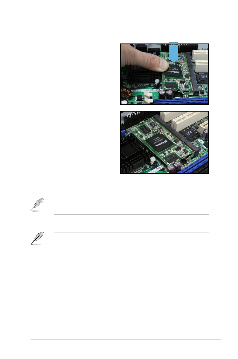
4. Press the board rmly until the
BMC socket retaining clips snap
back and secure the board in
place.
When installed, the board appears
as shown.
5. Reinstall the remote server system cover, then connect the power plug to a
grounded wall socket.
Everytime after the AC power is re-plugged, you have to wait for about 30
seconds for the system power up.
6. Insert the LAN cable plug to the IKVM LAN port for server management.
Refer to the Appendix for the location of the IKVM LAN port for server
management on various server motherboards.
7. For direct LAN conguration, connect the other end of the LAN cable to the
local/central server LAN port.
For connection to a network hub or router, connect the other end of the LAN
cable to the network hub or router.
ASUS ASMB3-IKVM 2-3
Page 20

To uninstall the board:
1. Simultaneously push the BMC
socket retaining clips outward until
the board tilts up.
2. Carefully pull the board out from
the BMC socket, then set aside.
2-4 Chapter 2: Installation
Page 21

2.3 Firmware update
You need to update the ASMB3-IKVM rmware before you start using the
ASMB3-IKVM board.
To update the rmware:
1. Insert the support CD into the optical drive.
2. Restart the remote server, then press <Del> during POST to enter the BIOS
setup.
3. Go to Boot menu and set the Boot Device Priority item to [CD-ROM].
4. When nished, press <F10> to save your changes and exit the BIOS setup.
5. On reboot, the main menu appears. Select
and press <Enter> to enter the sub-menu.
ASUS Server RS100-E5/PI2 System
FreeDOS command prompt
ASMB3-iKVM Firmware Update
6. A conrmation message appears, asking whether you want to update the
rmware or not. Press <Y> to update.
Are you sure you want to update ASMB3-iKVM Firmware now?
Yes or No [YN]?
The rmware updating process starts.
ASMB3-iKVM Firmware Update,
7. When the update process is completed, the following screen appears.
Starting Firmware Upgrade
Uploading Firmware File
0% ------------------- 50% ------------------ 100%
Upload complete.
Flashing Firmware (takes about 1min)
Successfully upgraded rmware.
Press any key to continue ...
8. Turn off the system and unplug the AC power cord for 5 seconds before
restarting the system
You may update rmware from the web-based user interface. Refer to page 3-25
for details.
ASUS ASMB3-IKVM 2-5
Page 22

2.4 BIOS conguration
You need to adjust the settings in the BIOS setup of the remote server for correct
conguration and connection to the central server.
•
Update the remote server BIOS le following the instructions in the
motherboard/system user guide. Visit the ASUS website (www.asus.com)
to download the latest BIOS le for the motherboard.
• The BIOS setup screens shown in this section are for reference purposes
only, and may not exactly match what you see on your screen.
2.4.1 AMI BIOS setup
You must congure the network settings of both the remote server and the local/
central server to establish communication for remote server control and monitoring.
Running the BIOS IPMI conguration
To congure the IPMI in the BIOS:
1. Restart the remote server, then press <Del> during POST to enter the BIOS
setup.
2. Go to the
sub-menu. Use this sub-menu to congure the IPMI settings.
3. When nished, press <F10> to save your changes and exit the BIOS setup.
Advanced or Server menu, then select the IPMI Conguration
IPMI Conguration
Advanced
IPMI Conguration
BMC Firmware version: 001.001
View BMC System Event Log
Clear BMC System Event Log
Set LAN Conguration
BMC Watch Dog Timer Action [Disabled]
v02.58 (C)Copyright 1985-2007, American Megatrends, Inc.
2-6 Chapter 2: Installation
BIOS SETUP UTILITY
View all events in the
BMC Event Log.
It will take a max. of
15 seconds to read all
BMC SEL records.
Select Screen
Select Item
Enter Go to Sub Screen
F1 General Help
F10 Save and Exit
ESC Exit
Page 23

View BMC System Event Log
Allows you to view all the events in the BMC event log. It will take a maximum
of 15 seconds to read all the BMC SEL records.
Advanced
Total Number of Entries: 0
SEL Entry Number: [N/A]
v02.58 (C)Copyright 1985-2007, American Megatrends, Inc.
BIOS SETUP UTILITY
Use +/- to traverse
the event log.
Select Screen
Select Item
+- Change Option
F1 General Help
F10 Save and Exit
ESC Exit
Clear BMC System Event Log
Allows you to clear the system event log. Press <Enter> to go to the sub
screen, and then select Ok to clear BMC System Event Log.
Set LAN Configuration
Allows you to set the BMC LAN Parameter settings.
Advanced
LAN Conguration.
Current IP address in BMC: 192.168.0.212
Current Subnet Mask in BMC: 255.255.255.0
Current Gateway Address in BMC: 000.000.000.000
Current MAC address in BMC: 00.E0.18.03.04.0C
IP Address Source [Static Mode]
IP Address [000.000.000.000]
Subnet Mask [000.000.000.000]
Gateway Address [000.000.000.000]
v02.58 (C)Copyright 1985-2007, American Megatrends, Inc.
BIOS SETUP UTILITY
Options
DHCP Mode
Static Mode
Select Screen
Select Item
+- Change Option
F1 General Help
F10 Save and Exit
ESC Exit
IP Address Source
Allows you to select the IP address source type. When set to [Static Mode], the
following three items become congurable, and you have to assign the IP address,
subnet mask and gateway address for the remote server. When set to [DHCP Mode],
you don’t have to assign the IP address, subnet mask and gateway address for the
remote server.
ASUS ASMB3-IKVM 2-7
Page 24

IP Address
Allows you to set the BMC IP address.
Subnet Mask
Allows you to set the BMC subnet mask. We recommend that you use the same
Subnet Mask you have specied on the operating system network for the used
network card.
Gateway Address
Allows you to set the gateway address. We recommend that you use the same
gateway address you have specied on the operating system network for the used
network card.
BMC Watch Dog Timer Action [Disabled]
Allows the BMC to reset or power down the system when the operating
system crashes or hangs. Conguration options: [Disabled] [Reset System]
[Power Down] [Power Cycle]
It is necessary to install ASWM (ASUS System Web-based Management) for
using this function.
2-8 Chapter 2: Installation
Page 25

2.4.2 Phoenix BIOS setup
Running the BIOS IPMI conguration
To congure the IPMI in the BIOS:
1. Restart the remote server, then press <Del> during POST to enter the BIOS
setup.
2. Go to the
to congure the IPMI settings.
3. When nished, press <F10> to save your changes and exit the BIOS setup.
Main Advanced Server Security Boot Exit
Console Redirection
DMI Event Logging
IPMI
F1 Help ↑↓ Select Item -/+ Change Values F9 Setup Defaults
ESC: Exit →← Select Menu Enter Select Sub-menu F10 Save and Exit
Server menu, then select the IPMI sub-menu. Use this sub-menu
PhoenixBIOS Setup Utility
Item Specic Help
Additional setup menus to
congure console.
IPMI Conguration
Main Advanced Server Security Boot Exit
IPMI Specication Version 2.0
BMC Firmware Version 1.04
System Event Logging [Enabled]
Clear System Event Log [Disabled]
Existing Event Log number 34
Event Log Control
SYS Firmware Progress [Disabled]
BIOS POST Errors [Enabled]
BIOS POST Watchdog [Disabled]
OS Boot Watchdog [Disabled]
Timer for loading OS (min) [ 10]
Time out action [No action]
Date Format to show [MM DD YYYY]
Date Separator [/]
F1 Help ↑↓ Select Item -/+ Change Values F9 Setup Defaults
ESC: Exit →← Select Menu Enter Select Sub-menu F10 Save and Exit
ASUS ASMB3-IKVM 2-9
PhoenixBIOS Setup Utility
IPMI
Item Specic Help
Enable/Disable IPMI
event logging. Disabling
will still log events
received via the system
interface.
Page 26

IPMI Specification Version
This item shows the auto-detected IPMI specication version.
BMC Firmware Version
This item shows the auto-detected BMC rmware version.
System Event Logging [Enabled]
Allows you to enable or disable the IPMI event logging feature.
Conguration options: [Enabled] [Disabled]
Clear System Event Log [Disabled]
Enabling this item forces the BIOS to clear the system event log on the next
cold boot. Conguration options: [Disabled] [Enabled]
Existing Event Log number
This item shows the auto-detected quantity of existing/remaining event logs.
Event Log Control
The following sub-items allow you to control the event logs.
SYS Firmware Progress [Disabled]
Allows you to enable or disable the POST progress log feature.
Conguration options: [Disabled] [Enabled]
BIOS POST Errors [Enabled]
Allows you to enable or disable the POST error log feature.
Conguration options: [Disabled] [Enabled]
BIOS POST Watchdog [Disabled]
Allows you to enable or disable the BIOS POST watchdog feature.
Conguration options: [Disabled] [Enabled]
OS Boot Watchdog [Disabled]
Allows you to enable or disable the OS boot watchdog feature.
Conguration options: [Disabled] [Enabled]
Timer for loading OS (min) [10]
Allows you to set the timer value for the watchdog timer. Use the numeric keypad
to enter your desired value, or use the <+>/<-> key to increase/decrease the value.
Valid input values range from [1] ~ [100].
Time out action [No action]
Allows you to specify what action to take if the OS fails to boot.
Conguration options: [No Action] [Reset] [Power Off] [Power Cycle]
Date Format to show [MM DD YYYY]
Allows you to choose the date format to be displayed.
Conguration options: [MM DD YYYY] [DD MM YYYY] [YYYY DD MM]
2-10 Chapter 2: Installation
Page 27

Date Separator [/]
Allows you to choose which character to use in date entries.
Conguration options: [.] [/]
Scroll down to display more items.
Main Advanced Server Security Boot Exit
System Event Log
System Event Log (list mode)
DHCP [Enabled]
IP Address [000.000.000.000]
F1 Help ↑↓ Select Item -/+ Change Values F9 Setup Defaults
ESC: Exit →← Select Menu Enter Select Sub-menu F10 Save and Exit
To congure your subnet mask and gateway address, refer to section 2.5.1 for
more information on using KIRARARI utility.
PhoenixBIOS Setup Utility
IPMI
Item Specic Help
Display the System Event
Log.
System Event Log
Press <Enter> to open the System Event Log, which allows you to view log
entries. Use the arrow keys to browse entry numbers.
Main Advanced Server Security Boot Exit
SEL Entry Number = 1
SEL Record ID = 0001
SEL Record Type = 02-System Event Record
Timestamp = 04/17/2006 16:10:44
Generator Id = 20 00
SEL Message Rev = 04
Sensor Type = 01 - Temperature
Sensor Number = 32 - CPU2temperature1
SEL Event Type = 01 - Threshold
Event Description = Upper Non-critical Going High, Assertion
SEL Event Data = 57 80 50
PhoenixBIOS Setup Utility
System Event Log
F1 Help ↑↓ Select Item -/+ Change Values F9 Setup Defaults
ESC: Exit →← Select Menu Enter Select Sub-menu F10 Save and Exit
ASUS ASMB3-IKVM 2-11
Page 28

System Event Log (list mode)
Press <Enter> to open the System Event Log in list mode.
Main Advanced Server Security Boot Exit
Event ID Sensor Name Sensor Type Date/Time Stamp
----------------------------------------------------------------------------- 001 CPU2temperature1 Temp 04/17/2006 16:10:44
Upper Non-critical Going High, Assertion
002 CPU2temperature1 Temp 04/17/2006 16:10:44
Upper Critical Going High, Assertion
003 CPU2temperature2 Temp 04/17/2006 16:10:44
Upper Non-critical Going High, Assertion
004 CPU2temperature2 Temp 04/17/2006 16:10:44
Upper Critical Going High, Assertion
005 DIMM_01 AMB temp Temp 04/17/2006 16:10:44
Lower Non-critical Going Low, Assertion
006 DIMM_01 AMB temp Temp 04/17/2006 16:10:45
Upper Critical Going Low, Assertion
F1 Help ↑↓ Select Item -/+ Change Values F9 Setup Defaults
ESC: Exit →← Select Menu Enter Select Sub-menu F10 Save and Exit
PhoenixBIOS Setup Utility
System Event Log (list mode)
Choose an event ID, then press <Enter> to view the details.
Main Advanced Server Security Boot Exit
[0001 CPU2temperature1 Temp 04/17/2006 16:10:44 ]
SEL Entry Number = 1
SEL Record ID = 0001
SEL Record Type = 02-System Event Record
Timestamp = 04/17/2006 16:10:44
Generator Id = 20 00
SEL Message Rev = 04
Sensor Type = 01 - Temperature
Sensor Number = 32 - CPU2temperature1
SEL Event Type = 01 - Threshold
Event Description = Upper Non-critical Going High, Assertion
SEL Event Data = 57 80 50
PhoenixBIOS Setup Utility
F1 Help ↑↓ Select Item -/+ Change Values F9 Setup Defaults
ESC: Exit →← Select Menu Enter Select Sub-menu F10 Save and Exit
DHCP
Allows you to enable or disable to set the IP source setting as DHCP.
IP Address
Allows you to provide information to set the BMC IP address.
2-12 Chapter 2: Installation
Page 29

2.5 Running the KIRARARI utility
The KIRARARI utility allows you to update the ASMB3-IKVM rmware, congure
the LAN setting for the remote server and change the user name/password in DOS
environment. This utility is available from the support CD that came with the package.
To run the KIRARARI utility:
1. Insert the support CD into the optical drive.
2. Restart the remote server, then press <Del> during POST to enter the BIOS
setup.
3. Go to Boot menu and set the Boot Device Priority item to [CD-ROM].
4. When nished, press <F10> to save your changes and exit the BIOS setup.
5. On reboot, the main menu appears. Select
then press <Enter> .
ASUS Server RS100-E5/PI2 System
FreeDOS command prompt
ASMB3-iKVM Firmware Update
6. When the C:> prompt appears, type CD \ASMB3\IKVM\MODEL\RS100-E5\
PI2, then press <Enter>.*
7. At the prompt, type
kirarari.exe, then press <Enter> to display the
KIRARARI Utility Help Menu. The screen appears as shown.
FreeDOS command prompt, and
Refer to the table on the next page for a description of the help menu options.
* The model name (for example RS100-E5) varies based on the motherboard
model you purchase.
ASUS ASMB3-IKVM 2-13
Page 30

KIRARARI Help Menu options
Options Description
kirarari reset Reset the device for BMC card
kirarari fw Show rmware information
kirarari fw upgrade <<lename>> Upgrade BMC rmware
kirarari ip
Show IP setting
kirarari ip set xxx.xxx.xxx.xxx Set IP to xxx.xxx.xxx.xxx
kirarari gw Show gateway setting
kirarari gw set xxx.xxx.xxx.xxx Set gateway to xxx.xxx.xxx.xxx
kirarari netmask Show net-mask setting
kirarari netmask set xxx.xxx.xxx.xxx Set net-mask to xxx.xxx.xxx.xxx
kirarari mac Show MAC setting
kirarari mac set xxx.xxx.xxx.xxx Set MAC to xxx.xxx.xxx.xxx
kirarari ipsrc Show IP source setting
kirarari ipsrc set <<static / bios / dhcp>> Set the IP source from static (no change)/
bios (assign by bios setting)/dhcp (get IP
from DHCP server)
kirarari admin Show administrator name
kirarari admin name xxxxx Set login name of administrator to xxxxx
kirarari admin passwd xxxxx Set login password of administrator to xxxxx
2.5.1 Updating the ASMB3-IKVM rmware
You may use KIRARARI utility to update the ASMB3-IKVM rmware.
To update the rmware:
1. Download the latest ASMB3-IKVM rmware from the ASUS website
(www.asus.com), and then save the le.
Save the le in a USB ash or in the hard disk drive of the remote server.
2. Follow steps 1-6 on previous page.
3. At the prompt, type
kirarari fw upgrade rs100e51.bin, then press
<Enter> to start updating the rmware.*
4. When the update process is complete, the following screen appears.
C:\ASMB3\IKVM\MODEL\RS100-E5\PI2>kirarari fw upgrade rs100e51.bin
Starting Firmware Upgrade
Uploading Firmware File
0% ------------------- 50% ------------------ 100%
********************************************************
Upload complete.
Flashing Firmware (takes about 1min)
Successfully upgraded rmware.
C:\ASMB3\IKVM\MODEL\RS100-E5\PI2>
2-14 Chapter 2: Installation
Page 31

5. Restart the remote server, enter the BIOS setup, then boot from the hard disk
drive.
* The le name (for example rs100e51.bin) varies based on the motherboard
model you purchase and the rmware version you download from website.
2.5.2 Conguring the LAN controller
Before you can establish connection to the ASMB3-IKVM board, you must
congure the LAN port for server management used by the remote server to
connect to the local/central server.
To congure the LAN port of the remote server:
1. Follow steps 1-6 on page 2-13.
2. At the prompt, type
IP source setting.
C:\ASMB3\IKVM\MODEL\RS100-E5\PI2>kirarari ipsrc
IP source: Static Address
C:\ASMB3\IKVM\MODEL\RS100-E5\PI2>
3. If the current IP source is set to DHCP address, then you don’t have to assign
the IP address to the remote server. If the current IP source is set to Static
address, then follow below instructions to complete the IP address assignment.
4. Type kirarari ip set xxx.xxx.xxx.xxx, then press <Enter> to
assign any IP address to the remote server. The screen displays the request
and response buffer. Write the remote server IP address in a piece of paper
for reference.
C:\ASMB3\IKVM\MODEL\RS100-E5\PI2>kirarari ip set 192.168.0.212
Successfully set IP address to 192.168.0.212
C:\ASMB3\IKVM\MODEL\RS100-E5\PI2>
kirarari ipsrc, then press <Enter> to see the current
Make sure that the assigned IP address for both remote and local/central
servers are in the same subnet. You can use the network settings utility in your
OS to check.
5. Congure your subnet mask (a) and gateway address (b) if necessary.
(a) Type
(b) Type
kirarari netmask set xxx.xxx.xxx.xxx
kirarari gw set xxx.xxx.xxx.xxx
6. Press <Enter> to effect the conguration.
7. Restart the remote server, enter the BIOS setup, then boot from the hard disk
drive.
8. Adjust the local/central server network settings, if necessary.
ASUS ASMB3-IKVM 2-15
Page 32

2.5.3 Conguring the user name and password
You may change your login name and password from the KIRARARI utility.
To change the login name and password:
1. Follow steps 1-6 on page 2-13.
2. At the prompt, type
change the login name.
C:\ASMB3\IKVM\MODEL\RS100-E5\PI2>kirarari admin name super
Successfully set administrator username to super
C:\ASMB3\IKVM\MODEL\RS100-E5\PI2>
3. Type kirarari admin passwd xxxxx, then press <Enter> to change the
password.
4. Restart the remote server, enter the BIOS setup, then boot from the hard disk
drive.
kirarari admin name xxxxx, then press <Enter> to
2-16 Chapter 2: Installation
Page 33

This chapter tells you how to use the
web-based user interface that the server
management board supports.
Chapter 3: Software
3
support
Page 34

3.1 Web-based user interface
The web-based user interface allows you to easily monitor the remote server’s
hardware information including temperatures, fan rotations, voltages, and power.
This application also lets you instantly power on/off or reset the remote server.
You should install JRE on remote console rst before using web-based
management. You can nd JRE from the folder JAVA of the ASMB3-IKVM
support CD. You can also download JRE from http://java.sun.com/javase/
downloads.
3.1.1 Loging in the utility
1. Ensure that the LAN cable of the computer is connected to the IKVM LAN
port of the remote server.
2. Open the web browser and type in the same IP address as the one in the
remote server.
3. The below screen appears. Enter the default user name (super) and
password (pass). Then click Login.
A Change Password screen appears asking you to change the password
when you log in the utility for the rst time. Type in the default password (pass)
in the Old password column, and then type in the new password in the New
password and Conrm New Password columns.
3-2 Chapter 3: Software support
Page 35

3.1.2 Home page
The home page displays when you login in the utility sucessfully.
1
6
1. Home: Click this icon to return to the home page.
Console: Click this icon to open the remote server window.
2.
Logout: Click this icon to log out the utility.
3.
Remote server screen: Displays the remote server screen. Click this screen
4.
Refresh: Click this icon to refresh the remote server screen.
5.
Function keys: Click each function key to start using its specic functions.
6.
2 3
4
5
to open the remote server window.
ASUS ASMB3-IKVM 3-3
Page 36
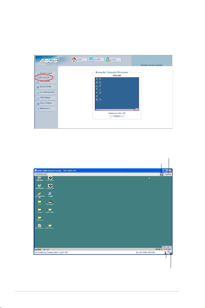
3.1.3 Remote Control
Click Remote Control to open its submenu, and then click KVM Console to open
remote server console screen.
Remote server console screen
Click to open the Options menu
Click to open/close the Drive Redirection window
Indicates the number of networks (users) that are
3-4 Chapter 3: Software support
connected via Console Redirection
Indicates the availability of keyboard and mouse
Page 37

Drive Redirection
The Drive Redirection function allows you to share your lcoal drives (oppy disk
drives, CD-ROM and hard disk drives) with users in the remote system. Click
Connect Drive, and then a Select a drive to redirect screen appears, allowing
you to select the drives you want to share in the remote system.
You have to check the box before Enable Write support item if you want to
write data into the shared drive. For enabling this function, the Force read-only
connectors item in the Drive Redirection window of the web-based utility
should be unchecked. See page 3-9 for details.
You may want to share an ISO image le with users in the remote system. Click
Connect ISO, and then a Choose ISO image to redirect screen appears,
allowing you to select the ISO image you wnat to share in the remote system.
ASUS ASMB3-IKVM 3-5
Page 38

Options menu
1
2
3
4
5
6
7
8
9
10
1. Monitor Only: Click to toggle the Monitor Only function on or off. If this
function is switched on, the remote server console screen could
be viewed only, no remote console interaction is possible.
Exclusive Access: Click to toggle the Exclusive Access function on or off.
2.
If this function is switched on, no other users could open
the remote console at the same time until you disable
this function or log off.*
Screenshot to clipboard: Click to capture a screenshot of the remote server
3.
console screen.
Readability Filter: Click to toggle the Readability Filter function on or off. If this
4.
function is switched on, most of the screen details will be
shown even if the scaling mode is set to higher percentage.
This function is available only with a JVM 1.4 or higher.
Scaling: Click to adjust the diaplay ratio of the remote server console screen.
5.
Local Cursor: Click to select the diaplay type of mouse cursor for the remote
6.
server console screen.
Chat Window: Click to open the chat window that allows you have conversation
7.
with the other users.
Soft Keyboard: Click to display the soft keyboard or select the input language
8.
and country mapping of the soft keyboard.
Local Keyboard: Click to select the input language for the remote console.
9.
Hotkeys: Click to select the hotkey to send a command to the remote server.
10.
* This option is available only when the RC settings (Exclusive Access)
permission has been enabled. Refer to 3.1.6 User Management for details.
3-6 Chapter 3: Software support
Page 39

3.1.4 Virtual Media
Click Virtual Media to open its submenu.
You may use the Drive Redirection funciton from the remote server console
screen. Refer to page 3-5 for details.
Floppy Disk
1
2
3
4
5
7
1. Floppy Disk: Click this function key to upload the data stored in the local
oppy disk image to the remote server.
Active Image - Drive 1: Displays the data that has been uploaded to Drive 1
2.
of the remote server.
Active Image - Drive 2: Displays the data that has been uploaded to Drive 2
3.
of the remote server.
Floppy Image Upload: Allows you to upload a binary image with a maximum
4.
size of 1.44 MB to the ASMB3-IKVM. This image will
be emulated to the remote server as a USB oppy
device.
Virtual Drive: Selects the drive in the remote server as a distination drive for
5.
you to upload your image data.
Floppy Image File: Click Browse to preview and select the les that you
6.
want to upload to the remote server.
Upload: Click to upload the le to the specied drive of the remote server.
7.
6
ASUS ASMB3-IKVM 3-7
Page 40

CD-ROM Image
2
1
7
9
1. CD-ROM Image: Click this function key to share data stored in your CD-ROM
image with other users in the remote server through the
Windows Share application via USB.
Active Image - Drive 1: Displays the le name of the data in Drive 1 of the
2.
remote server.
Active Image - Drive 2: Displays the le name of the data in Drive 2 of the
3.
remote server.
Image on Windows Share: Allows you to decide how you want to share
4.
the data stored in your CD-ROM image with the
users in the remote server.*
Virtual Drive: Selects the drive in the remote server that you want to share
5.
your data with.
Share host: Enter the IP address or the name of the system that you want to
6.
share data with via Windows Share.
Share name: Enter the name of the Windows Share you want to share data
7.
with in the remote server.
Path to image: Enter the location of source les that you want to share via
8.
Windows Share.
User/Password (Optional): Enter the user name and password of the
9.
Windows Share. Leave blank to use guest
account.
Set: Click to apply your selections.
10.
3
4
5
6
8
10
3-8 Chapter 3: Software support
Page 41

• * Ensure that you’ve installed
NWLink IPX/SPX/NetBIOS
compatible Transport Protocol
item for the network of the user with
the CD-ROM image.
• The remote connect ISO function is
for read only.
Drive Redirection
2
1
3
4
5
6
7 8
1. Drive Redirection: Click this function key to make local drives accessible for
other users via console redirection. This function allows
you to share your local drives (oppy disk drives, CD-ROM
and hard disk drives) with users in the remote system.
Active Image - Drive 1: Displays the le name of the data in Drive 1 of the
2.
remote server.
Active Image - Drive 2: Displays the le name of the data in Drive 2 of the
3.
remote server.
Drive Redirection: Use this window to congure Drive Redirection settings.
4.
Disable Drive Redirection: Check this box to disable Drive Redirection
5.
function. When this function is disabled, local
drives will not be accessible for other users in
remote server.
Force read-only connectors: Check this box to allow the data stored in
6.
local drives to be read in the remote system,
but could not be overwritten to ensure data
integrity and system security.
Apply: Click to apply your settings.
7.
Reset to defaults: Click to return to the default settings.
8.
ASUS ASMB3-IKVM 3-9
Page 42

Options
2
3
1
1. Options: Click this function key to open the Virtual Media options.
Virtual Media Options: Check this box to disable the funciton of Virtual
2.
Media options to prevent data stored in a local drive
from being accessed by the user in the remote
server.
Apply: Click to apply the setting if you’ve checked the box.
3.
Reset to defaults: Click to return to the default settings.
4.
4
3-10 Chapter 3: Software support
Page 43

3.1.5 System Health
Click System Health to open its submenu.
Chassis Control
2
1
1. Chassis Control: Click this function key to know the power information and
power management for the remote server.
Chassis Information: Allows you to know the power information for
2.
the remote server. Click Refresh to update the
information on this window.
Power Control: Click Power On to turn on the remote server; click Power
3.
Down to turn off the remote server; click Power Cycle to
turn off the remote server and turn it on later; click Reset to
reset the remote console.
Click Power Cycle to turn off the remote server, and allow the remote server to
be powered on automatically after about 3 minutes.
6
3
ASUS ASMB3-IKVM 3-11
Page 44

Monitor Sensors
2
1
1. Monitor Sensors: Click this function key to display the health monitoring
information for the remote server.
Monitoring Sensors: Allows you to see the related health monitoring
2.
information for the remote server. Click Refresh to
update the information on this window.
System Event Log
1
1. System Event Log: Click this function key to display the system health event
log information for the remote server.
3-12 Chapter 3: Software support
Page 45
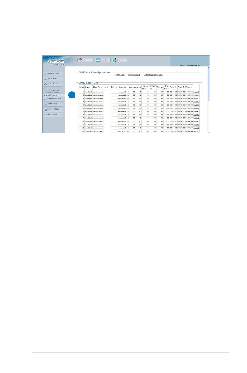
Alert Settings
1
1. Alert Settings: Click this function key to enter the alert settings submenu for
the remote server.
ASUS ASMB3-IKVM 3-13
Page 46

3.1.6 User Management
Click User Management to open its submenu.
Change Password
1
1. Change Password: Click this function key to enter the Change Password
window. After entering all the necessary information,
click Apply to apply the new settings.
Users & Groups
2
1
3
1. Users & Groups: Click this function key to enter the user management and
group management submenus.
Users Management: Allows you to setup the related user information.
2.
Group Management: Allows you to setup the group information for better
3.
user management.
3-14 Chapter 3: Software support
Page 47

Permissions
2
3
1
1. Permissions: Click this function key to enter the user/group permissions
submenu.
User / Group Permissions: Selects the user and group that you want to
2.
show the permission details.
Update: Click to update the permission information.
3.
You can only set the user permission by setting group only.
ASUS ASMB3-IKVM 3-15
Page 48

3.1.7 KVM Settings
Click KVM Settings to open its submenu.
User Console
Click User Console to open the setup window. From the window you could
congure the detailed settings for the remote server console.
Keyboard/Mouse
Click Keyboard/Mouse to open the setup window. From the window you could
congure the detailed settings for the keyboard and mouse.
Set USB Mouse Type to [Windows > = 2000, Mac OS X] if your operating
system is Windows®; set USB Mouse Type to [Other Operating Systems] if your
operating system is Linux.
3-16 Chapter 3: Software support
Page 49

3.1.8 Device Settings
Click Device Settings to open its submenu.
Network
2
1
Scroll down to display more items.
1. Network: Click this function key to enter the network submenus.
Network Basic Settings: Allows you to congure basic settings for the
2.
Network Miscellaneous Settings: Allows you to congure other settings for
3.
LAN Interface Settings: Allows you to congure the LAN interface speed
4.
3
4
network.
the network.
and LAN interface duplex mode.
ASUS ASMB3-IKVM 3-17
Page 50

Dynamic DNS
2
1
1. Dynamic DNS: Click this function key to enter the dynamic DNS submenus
and congure its related settings.
Enable Dynamic DNS: Check this box to enable the dynamic DNS service.
2.
3-18 Chapter 3: Software support
Page 51

Security
2
3
4
1
5
Scroll down to display more items.
6
7
1. Security: Click this function key to enter the security submenus.
HTTP Encryption: Allows you to set to use the the HTTPS connection to
2.
access the web.
KVM Encryption: Allows you to set to use the encrypted connection.
3.
IP Access Control: Allows you to congure the detailed IP access control
4.
settings.
Group based System Access Control: Allows you to limit several user
5.
access to the network by identifying
their IP addresses.
User Blocking: Allows you to set the conditions when a user will be blocked.
6.
Login limitations: Allows you to congure the login limitations.
7.
ASUS ASMB3-IKVM 3-19
Page 52

Certicate
2
1
1. Certicate: Click this function key to enter the Certicate submenus and
congure its related settings.
Certicate Signing Request (CSR): Allows you to dene the Certicate
2.
Signing Request (CSR) form. Click
Create to apply the settings.
Date/Time
2
1
1. Date/Time: Click this function key to enter the Date/Time submenus.
Date/Time Settings: Allows you to congure the internal realtime clock for
2.
the remote server.
3-20 Chapter 3: Software support
Page 53

Authentication
2
1
1. Authentication: Click this function key to enter the Authentication
submenus.
Authentication Settings: Allows you to congure the authentication settings.
2.
Click Apply to apply the settings.
Event Log
2
1
ASUS ASMB3-IKVM 3-21
Page 54

Scroll down to display more items.
3
1. Event Log: Click this function key to enter the Event Log submenus.
Event Log Targets: Allows you to congure the event log targets.
2.
•
•
•
List Logging Enabled: Check the box to enable the event log list.
NFS Logging Enabled: Check the box to enable the NFS log list.
SMTP Logging Enabled: Check the box to enable to send e-mails to
the address you’ve specied in the Receiver
Email Address column.
•
SNMP Logging Enabled: Check the box to enable to send a SNMP trap
to a specied destination IP address.
Event Log Assignments: Allows you to select the events that will generate
3.
an event log.
3-22 Chapter 3: Software support
Page 55

SNMP Settings
2
1
1. SNMP Settings: Click this function key to enter the SNMP submenus.
SNMP Settings: Allows you to congure the Simple Network Management
2.
Protocol (SNMP) settings.
ASUS ASMB3-IKVM 3-23
Page 56

3.1.9 Maintenance
Click Maintenance to open its submenu.
Device Information
2
1
1. Device Information: Click this function key to enter the Device Information
submenus.
Device Information: Displays the detailed information of the ASMB3-IKVM
2.
board.
Connected Users: Displays the user name, IP address and status of the
3.
users connected to the remote system.
3
Event Log
2
1
1. Event Log: Click this function key to enter the Event Log submenus.
Event Log: Displays the event log list.
2.
3-24 Chapter 3: Software support
Page 57

Update Firmware
2
1
1. Update Firmware: Click this function key to enter the Firmware Update
submenus.
Firmware Upload: Type in the name of the rmware you want to update or
2.
click Browse to select the rmware le. Click Upload to
start updating the rmware. It might take a few minutes to
complete the procedure.
Unit Reset
2
3
4
1
1. Unit Reset: Click this function key to enter the Unit Reset submenus.
Reset Keyboard/Mouse: Click to reset keyboard/mouse.
2.
Reset Video Engine: Click to reset the video and its controller.
3.
Reset Device: Click to reset the IPMI rmaware.
4.
ASUS ASMB3-IKVM 3-25
Page 58

3-26 Chapter 3: Software support
Page 59

The Appendix shows the location of the IKVM
LAN port for server management and BMC
socket on several motherboards. This section
also presents common problems that you
may encounter when installing or using the
server management board.
Appendix: Reference
A
information
Page 60
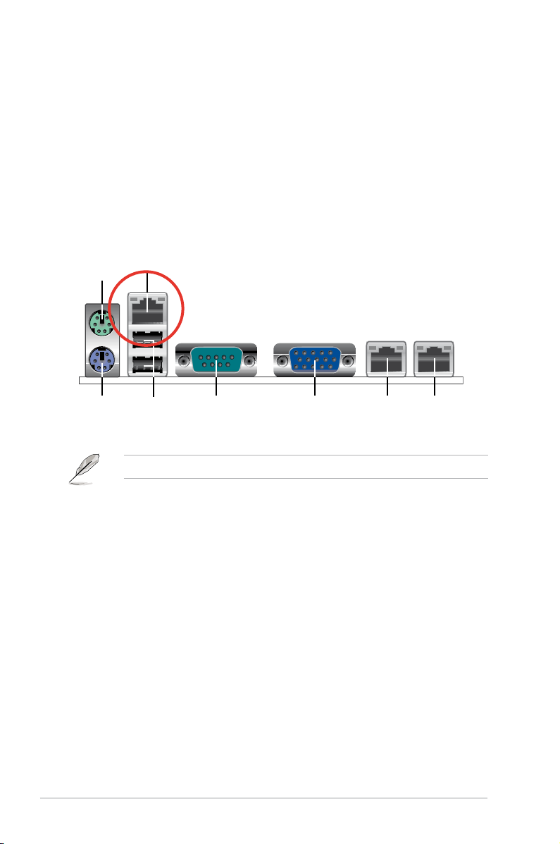
A.1 LAN port for server management
1
8 56 4
2
7
3
The ASUS server motherboards that support the ASMB3-IKVM comes with an
IKVM LAN port. You must use the IKVM LAN port for server management to
connect the remote server to the local/central host (direct LAN connection) or to
the network hub or router.
Refer to the illustrations below to identify the IKVM LAN port for server
management on some server motherboards.
P5BV-M/RS100-E5 motherboard
You can refer to motherboard manual for the location of IKVM LAN port.
A-2 Appendix: Reference information
Page 61
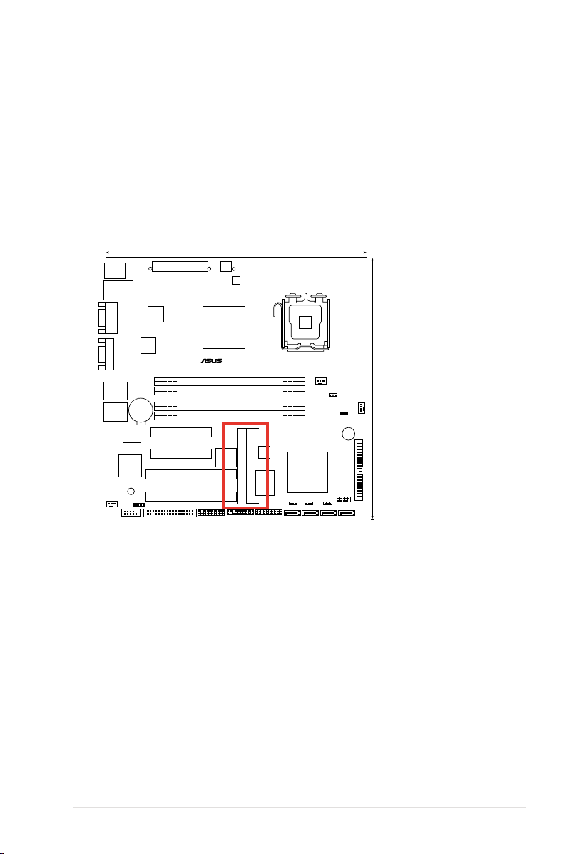
A.2 BMC socket
24.5cm (9.6in)
24.5cm (9.6in)
DDR2 DIMM_A1 (64 bit,240-pin module)
DDR2 DIMM_A2 (64 bit,240-pin module)
DDR2 DIMM_B1 (64 bit,240-pin module)
DDR2 DIMM_B2 (64 bit,240-pin module)
PCI3
PCIE1
PCIE2
PCI4
Super I/O
FRNT_FAN1
CPU_FAN1
REAR_FAN1
CR2032 3V
Lithium Cell
CMOS Power
AUX_PANEL1
FLOPPY1
SB_PWR1
RECOVERY1
®
P5BV-M/RS100-E5
PS/2KBMS
T: Mouse
B: Keyboard
LAN_USB12
LAN1
VGA1
COM1
LAN2
LGA775
CHAFAN_SET1
RAID_SEL1
HDLED1
TPM1
ATX12V1
EATXPWR1
CPUFAN_SET1
BUZZ1
PRI_IDE1
USB34
SATA3 SATA1 SATA2 SATA4
CLRTC1
PANEL1
ASMB3
COM2
8Mb
BIOS
BCM
5721
BCM
5721
Intel 3200
MCH
Intel
ICH7R ICH
XGI
Z9s
Qimonda
0706
ICS
9LPRS918BKL
ISL
6312
The ASUS server motherboards that support the ASMB3-IKVM comes with a
Baseboard Management Controller (BMC) socket.
Refer to the illustrations below to locate the BMC socket on different server
motherboards.
P5BV-M/RS100-E5 motherboard
ASUS ASMB3-IKVM A-3
Page 62

A.3 Troubleshooting
This troubleshooting guide provides answers to some common problems that you
may encounter while installing and/or using ASUS ASMB3-IKVM. These problems
require simple troubleshooting that you can perform by yourself. Contact the
Technical Support if you encounter problems not mentioned in this section.
Problem Solution
The local/central server cannot connect
to the ASMB3-IKVM board
The cursor on the remote server
console screen (refer to the screenshot
on section 3.1.3) shows duplicates or
becomes abnormal
Cannot use Virtual Media to share the
data stored in the CD-ROM image with
the users in the remote server.
1. Check if the LAN cable is connected
2. Make sure that the IP address of
3. Check if the IP source is set to [DHCP].
1. Check if the mouse setting is correct.
2. Click
3. Click
Check if you’ve installed NWLink
IPX/SPX/NetBIOS compatible Transport
Protocol item for the network. If no, follow
below instruction to install the item.
1. Right-click the
2. Right-click
3. Click
4. Select
5. Select
to the IKVM LAN port. See
section A.1 LAN port for server
management for details.
both the remote and local/central
servers are on the same subnet.
(See chapter 2 for details.) Try “ping
<romete_server_bmc_ip>” on local/
central server and make sure romete
server could reply the ping request.
When set to [DHCP], you’ll not be able
to congure the IP address.
Select different USB mouse type
in drop-down menu for different
operating sytems. See section 3.1.7
KVM Settings for details.
Options in the remote server
console screen. From the pop-up
menu, click Local Cursor, and then
select Transparent or default.
Synchronize mouse in the
remote server console screen. (Only
for Linux operating system)
Network Connections
icon on the Windows® taskbar, and then
select Open Network Connections.
Local Area Connection,
and then select Properties.
Install button, the Select Network
Connection Type screen appears.
Protocol, and then click Add....
NWLink IPX/SPX/NetBIOS
compatible Transport Protocol, and
then click OK to install.
A-4 Appendix: Reference information
 Loading...