

Page 1
BA5190/AS-D900
ASUS PC
User Manual
Page 2

E4638
First Edition V1
April 2009
Copyright © 2009 ASUSTeK Computer Inc. All Rights Reserved.
No part of this manual, including the products and software described in it, may be reproduced,
transmitted, transcribed, stored in a retrieval system, or translated into any language in any form or by any
means, except documentation kept by the purchaser for backup purposes, without the express written
permission of ASUSTeK Computer Inc. (“ASUS”).
Product warranty or service will not be extended if: (1) the product is repaired, modied or altered, unless
such repair, modication of alteration is authorized in writing by ASUS; or (2) the serial number of the
product is defaced or missing.
ASUS PROVIDES THIS MANUAL “AS IS” WITHOUT WARRANTY OF ANY KIND, EITHER EXPRESS
OR IMPLIED, INCLUDING BUT NOT LIMITED TO THE IMPLIED WARRANTIES OR CONDITIONS OF
MERCHANTABILITY OR FITNESS FOR A PARTICULAR PURPOSE. IN NO EVENT SHALL ASUS, ITS
DIRECTORS, OFFICERS, EMPLOYEES OR AGENTS BE LIABLE FOR ANY INDIRECT, SPECIAL,
INCIDENTAL, OR CONSEQUENTIAL DAMAGES (INCLUDING DAMAGES FOR LOSS OF PROFITS,
LOSS OF BUSINESS, LOSS OF USE OR DATA, INTERRUPTION OF BUSINESS AND THE LIKE),
EVEN IF ASUS HAS BEEN ADVISED OF THE POSSIBILITY OF SUCH DAMAGES ARISING FROM ANY
DEFECT OR ERROR IN THIS MANUAL OR PRODUCT.
SPECIFICATIONS AND INFORMATION CONTAINED IN THIS MANUAL ARE FURNISHED FOR
INFORMATIONAL USE ONLY, AND ARE SUBJECT TO CHANGE AT ANY TIME WITHOUT NOTICE,
AND SHOULD NOT BE CONSTRUED AS A COMMITMENT BY ASUS. ASUS ASSUMES NO
RESPONSIBILITY OR LIABILITY FOR ANY ERRORS OR INACCURACIES THAT MAY APPEAR IN THIS
MANUAL, INCLUDING THE PRODUCTS AND SOFTWARE DESCRIBED IN IT.
Products and corporate names appearing in this manual may or may not be registered trademarks or
copyrights of their respective companies, and are used only for identication or explanation and to the
owners’ benet, without intent to infringe.
ii
Page 3

ASUS contact information
ASUSTeK Computer Inc.
Address 15 Li-Te Road, Peitou, Taipei, Taiwan 11259
Telephone +886-2-2894-3447
Fax +886-2-2890-7798
E-mail info@asus.com.tw
Web site www.asus.com.tw
Technical Support
Telephone +86-21-38429911
Online support support.asus.com
ASUS Computer International (America)
Address 800 Corporate Way, Fremont, CA 94539, USA
Telephone +1-510-739-3777
Fax +1-510-608-4555
Web site usa.asus.com
Technical Support
Telephone +1-812-282-2787
Support fax +1-812-284-0883
Online support support.asus.com
ASUS Computer GmbH (Germany and Austria)
Address Harkort Str. 21-23, D-40880 Ratingen, Germany
Fax +49-2102-959911
Web site www.asus.de
Online contact www.asus.de/sales
Technical Support
Telephone (Component) +49-1805-010923
Telephone (System/Notebook/Eee/LCD) +49-1805-010920
Support Fax +49-2102-9599-11
Online support support.asus.com
iii
Page 4

Contents
Notices ........................................................................................................ vii
Safety information .................................................................................... viii
General precautions ................................................................................... ix
About this guide .......................................................................................... x
System package contents ......................................................................... xii
Chapter 1: System introduction
1.1 Front panel .................................................................................... 1-2
1.2 Rear panel ..................................................................................... 1-3
1.3 Connecting to the keyboard and the mouse ............................. 1-4
1.4 Connecting to other peripheral devices .................................... 1-4
Chapter 2: Getting started
2.1 Installing an operating system ................................................... 2-2
2.2 Powering your system ................................................................. 2-2
2.3 Support DVD information ............................................................ 2-3
2.3.1 Running the Support DVD .............................................. 2-3
2.3.2 Drivers menu ................................................................... 2-4
2.3.3 Utilities menu .................................................................. 2-5
2.3.4 Make disk menu .............................................................. 2-6
2.3.5 Manual menu .................................................................. 2-7
2.3.6 ASUS contact information ............................................... 2-7
2.3.7 Other information ............................................................ 2-8
2.4 ASUS AI Manager ....................................................................... 2-10
2.4.1 Installing AI Manager .................................................... 2-10
2.4.2 Launching AI Manager .................................................. 2-10
2.4.3 AI Manager Quick Bar ................................................... 2-10
2.4.4 Main ...............................................................................2-11
2.4.5 My favorites ................................................................... 2-15
2.4.6 Support ......................................................................... 2-16
2.4.7 Information .................................................................... 2-16
2.5 ASUS MyLogo 2™ ...................................................................... 2-17
2.6 ASUS EPU–6 Engine .................................................................. 2-19
2.7 ASUS Express Gate ................................................................... 2-23
2.8 Realtek Teaming Utility .............................................................. 2-31
iv
Page 5

2.9 RAIDcongurations .................................................................. 2-35
2.9.1 RAID denitions ............................................................ 2-35
2.9.2 Installing Serial ATA hard disks ..................................... 2-36
2.9.3 Intel® RAID congurations ............................................. 2-36
2.9.4 Marvell® SAS RAID congurations ................................ 2-44
2.10 Creating a RAID driver disk ....................................................... 2-53
2.10.1 Creating a RAID driver disk without entering the OS .... 2-53
2.10.2 Creating a RAID driver disk in Windows
® ........................................... 2-53
2.11 Loading the initial OS default settings ..................................... 2-55
2.12 Recovery DVD ............................................................................ 2-55
2.12.1 Recovering a Windows® XP OS: ................................... 2-55
2.12.2 Recovering a Windows® Vista OS: ................................ 2-56
Chapter 3: BIOS setup
3.1 Managing and updating your BIOS ............................................ 3-2
3.1.1 ASUS Update utility ........................................................ 3-2
3.1.2 ASUS EZ Flash 2 utility ................................................... 3-5
3.1.3 Creating a bootable oppy disk ....................................... 3-6
3.1.4 AFUDOS utility ................................................................ 3-7
3.1.5 ASUS CrashFree BIOS 3 utility ...................................... 3-9
3.2 BIOS setup program .................................................................. 3-10
3.2.1 BIOS menu screen .........................................................3-11
3.2.2 Menu bar ........................................................................3-11
3.2.3 Navigation keys ..............................................................3-11
3.2.4 Menu items ................................................................... 3-12
3.2.5 Sub-menu items ............................................................ 3-12
3.2.6 Conguration elds ....................................................... 3-12
3.2.7 Pop-up window ............................................................. 3-12
3.2.8 Scroll bar ....................................................................... 3-12
3.2.9 General help ................................................................. 3-12
3.3 Main menu .................................................................................. 3-13
3.3.1 System Time ................................................................. 3-13
3.3.2 System Date ................................................................. 3-13
3.3.3 Language ...................................................................... 3-13
3.3.4 SATA 1-6 ....................................................................... 3-14
v
Page 6

3.3.5 Storage Conguration ................................................... 3-15
3.3.6 AHCI Conguration ....................................................... 3-16
3.3.7 System Information ....................................................... 3-17
3.4 Advanced menu ......................................................................... 3-18
3.4.1 CPU Conguration ........................................................ 3-18
3.4.2 Chipset .......................................................................... 3-21
3.4.3 Onboard Device Conguration ...................................... 3-22
3.4.4 USB Conguration ........................................................ 3-23
3.4.5 PCIPnP ......................................................................... 3-24
3.5 Power menu ................................................................................ 3-25
3.5.1 Suspend Mode .............................................................. 3-25
3.5.2 Repost Video on S3 Resume ........................................ 3-25
3.5.3 ACPI 2.0 Support .......................................................... 3-25
3.5.4 ACPI APIC Support ....................................................... 3-25
3.5.5 APM Conguration ........................................................ 3-26
3.5.6 Hardware Monitor ......................................................... 3-27
3.6 Boot menu .................................................................................. 3-28
3.6.1 Boot Device Priority ...................................................... 3-28
3.6.2 Boot Settings Conguration .......................................... 3-29
3.6.3 Security ......................................................................... 3-30
3.7 Tools menu ................................................................................. 3-32
3.7.1 ASUS EZ Flash 2 .......................................................... 3-32
3.7.2 Express Gate ................................................................ 3-33
3.7.3 ASUS O.C. Prole ......................................................... 3-34
3.7.4 Ai Net 2 ......................................................................... 3-35
3.8 Exit menu .................................................................................... 3-36
Appendix: G.P. Diagnosis card
A.1 G.P. Diagnosis card installation ..................................................A-2
A.1.1 G.P. Diagnosis card layout ..............................................A-2
A.1.2 Installing G.P. Diagnosis card .........................................A-2
A.1.3 G.P. Diagnosis card check codes....................................A-3
vi
Page 7

Notices
Federal Communications Commission Statement
This device complies with Part 15 of the FCC Rules. Operation is subject to the
following two conditions:
•
This device may not cause harmful interference, and
•
This device must accept any interference received including interference that
may cause undesired operation.
This equipment has been tested and found to comply with the limits for a
Class B digital device, pursuant to Part 15 of the FCC Rules. These limits are
designed to provide reasonable protection against harmful interference in a
residential installation. This equipment generates, uses and can radiate radio
frequency energy and, if not installed and used in accordance with manufacturer’s
instructions, may cause harmful interference to radio communications. However,
there is no guarantee that interference will not occur in a particular installation. If
this equipment does cause harmful interference to radio or television reception,
which can be determined by turning the equipment off and on, the user is
encouraged to try to correct the interference by one or more of the following
measures:
•
Reorient or relocate the receiving antenna.
•
Increase the separation between the equipment and receiver.
•
Connect the equipment to an outlet on a circuit different from that to which the
receiver is connected.
•
Consult the dealer or an experienced radio/TV technician for help.
The use of shielded cables for connection of the monitor to the graphics card is
required to assure compliance with FCC regulations. Changes or modications
to this unit not expressly approved by the party responsible for compliance
could void the user’s authority to operate this equipment.
Canadian Department of Communications Statement
This digital apparatus does not exceed the Class B limits for radio noise emissions
from digital apparatus set out in the Radio Interference Regulations of the
Canadian Department of Communications.
This class B digital apparatus complies with Canadian ICES-003.
REACH
Complying with the REACH (Registration, Evaluation, Authorisation, and
Restriction of Chemicals) regulatory framework, we published the chemical
substances in our products at ASUS REACH website at http://green.asus.com/
english/REACH.htm.
vii
Page 8

Safety information
Electrical safety
• To prevent electric shock hazard, disconnect the power cable from the electric
outlet before relocating the system.
• When adding or removing any devices to or from the system, contact a
qualied service technician or your retailer. Ensure that all the power cables for
the devices are unplugged before the signal cables are connected. If possible,
disconnect all the power cables from the existing system before you add or
remove a device to or from the system.
•
If the power supply is broken, do not try to x it by yourself. Contact a qualied
service technician or your retailer.
Operation safety
• Before installing devices into the system, carefully read all the documentation
that comes with the package.
• Before using the product, ensure that all cables are correctly connected and
the power cables are not damaged. If you detect any damage, contact your
dealer immediately.
• To avoid short circuits, keep paper clips, screws, and staples away from
connectors, slots, sockets, and circuitry.
• Avoid dust, humidity, and extreme temperatures. Do not place this product in a
location where it may get wet. Place this product on a at and stable surface.
• When using this product, do not block any air inlet/outlet on the chassis.
• We recommend that you use this product in environments with an ambient
temperature below 40ºC.
• If you encounter technical problems with this product, contact a qualied
service technician or your retailer.
Lithium-Ion Battery Warning
CAUTION: Danger of explosion if battery is incorrectly replaced. Replace
only with the same or equivalent type recommended by the manufacturer.
Dispose of used batteries according to the manufacturer’s instructions.
VORSICHT: Explosionsgetahr bei unsachgemäßen Austausch der Batterie.
Ersatz nur durch denselben oder einem vom Hersteller empfohlenem
ähnljchen Typ. Entsorgung gebrauchter Batterien nach Angaben des
Herstellers.
viii
LASER PRODUCT WARNING
CLASS 1 LASER PRODUCT
Page 9

General precautions
Before using the ASUS BA5190/AS-D900 Desktop PC, carefully read the general
precautions below. Improper operation could lead to personal injury or damage to
the product.
• Before using this product, ensure that all components are correctly installed
and all cables are correctly connected. If you detect any damage, contact your
dealer immediately.
• Avoid dust and extreme temperatures. Do not place this product in a location
where it may receive direct sunlight.
• Do not place this product in a location where it may get wet.
• Do not block the air vents on the chassis. Always provide proper ventilation for
this product.
• Before turning on the system, check if all the peripherals are correctly
connected.
• To avoid short circuits, keep scraps, screws, and threads away from
connectors, slots, sockets, and circuitry.
• Do not insert any object or spill liquid into the air vents on the chassis.
• If this product has been used for a long time, avoid direct contact with the
heatsinks and the surfaces of IC as they may become very warm and hot.
Check if the system receives proper ventilation.
• Before you add or remove a peripheral device to or from the system, ensure
that you unplugged the system from the power source.
• If the power supply is broken, do not try to x it by yourself. Contact a qualied
service technician or your retailer.
• Do not service this product yourself.
• Though the system casing is elaborately designed to protect users from
scratches, be careful with those sharp tips and edges. Put on a pair of gloves
before you remove or replace the system cover.
• Unplug this product from the power source when it is left unused for a long
period of time.
• We recommend that you use this product in environments with an ambient
temperature below 40ºC.
• Use this product only with the correct voltage as instructed by the
manufacturer.
• To prevent re or electric shock, do not overload power outlets and extension
cords.
• Warning: Ensure that you replace the battery with a correct type; otherwise, it
may cause an explosion hazard.
ix
Page 10

About this guide
Audience
This guide provides general information about ASUS BA5190/AS-D900 Desktop
PC and instructions on how to use the Support DVD that comes with the system
package.
How this guide is organized
This guide contains the following parts:
Chapter 1: System introduction
This chapter gives a general description of ASUS BA5190/AS-D900 Desktop PC.
The chapter lists the system features, including introduction on the front and rear
panels.
Chapter 2: Getting started
This chapter helps you power up the system and install drivers and utilities from
the Support DVD.
Chapter 3: BIOS setup
This chapter tells how to change the system settings through the BIOS setup
menus. Detailed descriptions of the BIOS parameters are also provided.
Appendix: G.P. Diagnosis card
This chapter gives an introduction on the G.P. Diagnosis card that provides quick
system checks and displays errors on the LED display.
x
Page 11

Conventions used in this guide
To ensure that you perform certain tasks properly, take note of the following
symbols used throughout this guide.
WARNING: Information to prevent injury to yourself when trying to
complete a task.
CAUTION: Information to prevent damage to the components when
trying to complete a task.
IMPORTANT: Instructions that you MUST follow to complete a task.
NOTE: Tips and additional information to aid in completing a task.
Wheretondmoreinformation
Refer to the following sources for additional information and for product and
software updates.
1. ASUS Websites
The ASUS websites worldwide provide updated information on ASUS
hardware and software products. Refer to the ASUS contact information.
2. Optional Documentation
Your product package may include optional documentation, such as warranty
yers, that may have been added by your dealer. These documents are not
part of the standard package.
xi
Page 12
System package contents
Check your BA5190/AS-D900 system package for the following items.
Standard items
1. ASUS BA5190/AS-D900 Desktop PC with
• ASUS Desktop x1
• Mouse x1
• Keyboard x1
2. Cables
• Power cord x1
3. Accessories
• Mouse pad x1
4. DVD
• Support DVD x1
5. Documentation
• User Manual x1
• Warranty card x1
If any of the above items is damaged or missing, contact your retailer
immediately.
Optional items
1. Optical disk drive (ODD)
2. Storage card reader
3. LAN cable
4. Power strip
• Optional items are not included in the system package. They are purchased
separately.
• Specications depend on the desktop PC you purchased. Check with your
supplier for the exact specications.
xii
Page 13
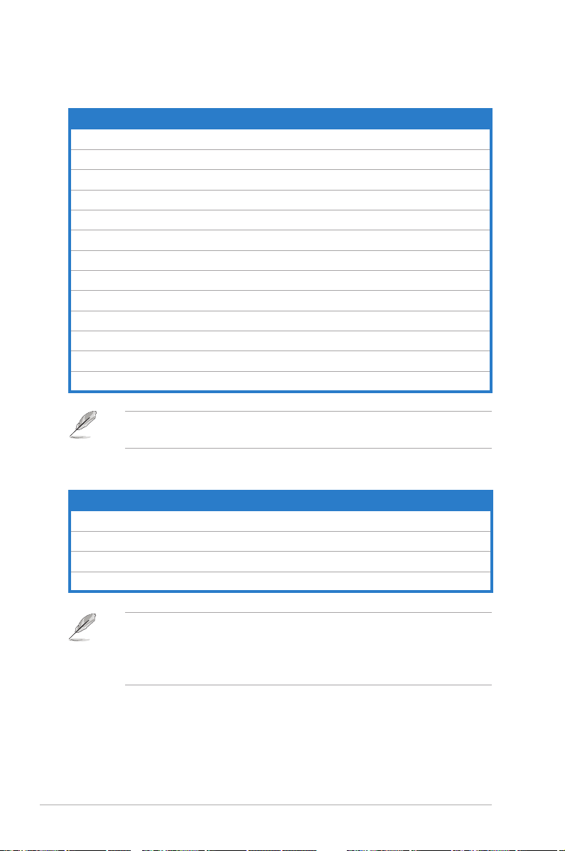
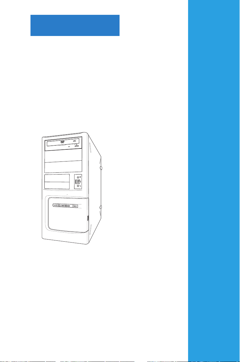
Chapter 1
This chapter gives a general description
of the desktop PC. The chapter lists the
system features including introduction on
the front and rear panels.
System introduction
Page 14
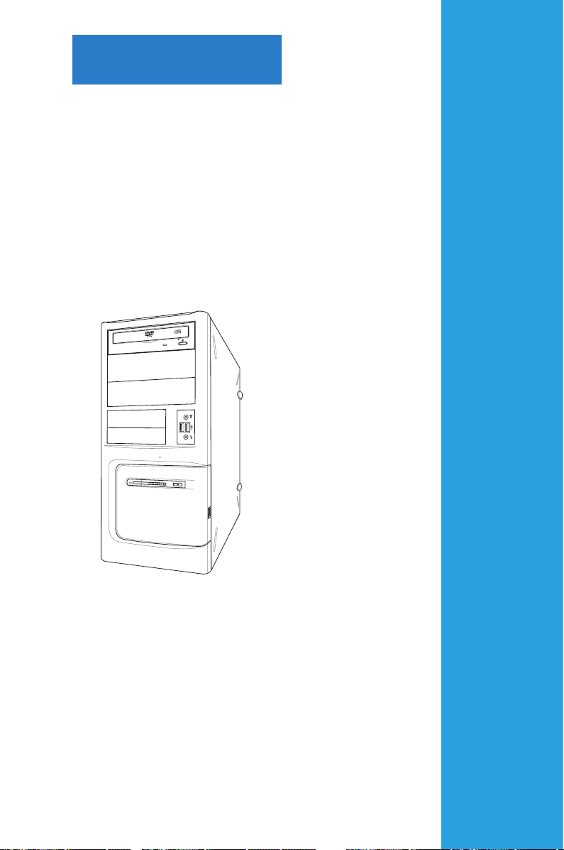
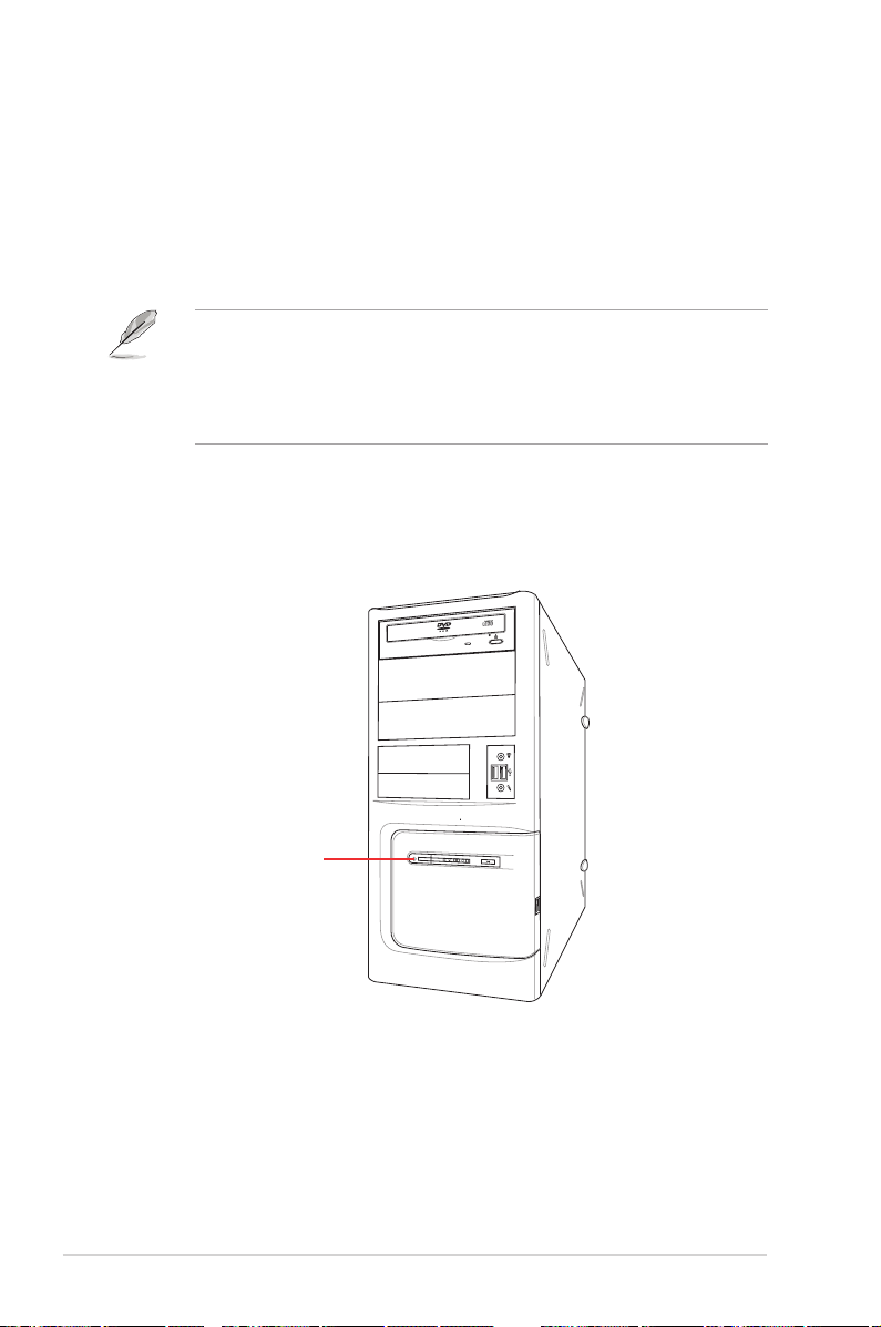
1.1 Front panel
The ASUS BA5190/AS-D900 Desktop PC includes an ASUS motherboard, a power
supply unit, a front panel, and a rear panel. All of these components are integrated
in a system casing elaborately designed by ASUS.
3 x 5.25 inch optical disk drive bays
2 x 3.5 inch drive bays
Power button
Power LED
HDD LED
• The storage card reader and optical disk drive are optional items which are
not included in the system package. They are purchased separately.
• The 5.25 inch optical disk drive bay is for a 5.25 inch DVD-ROM / CD-RW /
DVD-RW device.
• The 3.5 inch drive bay is for a 3.5 inch hard disk drive / USB storage card
reader.
• The storage card reader is for Secure Digital™ / MultimediaCard / Memory
Stick® / CompactFlash® / Microdrive™ storage cards and smart cards.
1 x Headphone port
2 x USB 2.0 ports
1 x Microphone port
Reset button
2 x USB 2.0 ports
1-2 Chapter 1: System introduction
Page 15
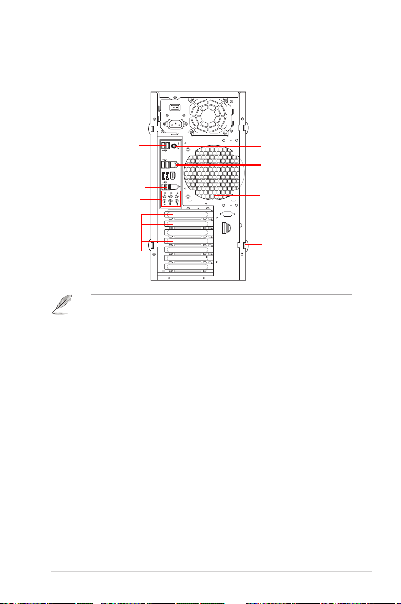
1.2 Rear panel
CTR
BASS
LINE
IN
FRONT
MIC IN
REAR
S P K
SIDE
S P K
2-eSATA
1394
The system rear panel includes the power connector and several I/O ports that
allow you to conveniently connect devices.
1 x Power switch
1 x Power connector
2 x USB 2.0 ports
2 x USB 2.0 ports
2 x eSATA ports
2 x USB 2.0 ports
8-channel audio ports
5 x Expansion slots*
Only ve expansion slots are available on this desktop PC.
1 x PS/2 Keyboard/Mouse Combo port
1 x RJ-45 port
1 x 1394 port
1 x RJ-45 port
Air vents
Expansion slot lock
Side cover lock
1-3ASUS BA5190/AS-D900
Page 16
1.3 Connecting to the keyboard and the
CTR
BASS
LINE
IN
FRONT
MIC IN
REAR
S P K
SIDE
S P K
2-eSATA
1394
mouse
Your ASUS BA5190/AS-D900 Desktop PC package includes a PS/2 keyboard
or a USB keyboard and a USB mouse. Connect the PS/2 keyboard to the PS/2
keyboard port at the rear panel or the USB keyboard to a USB port either at the
rear panel or front panel. Connect the USB mouse to a USB port either at the rear
panel or front panel.
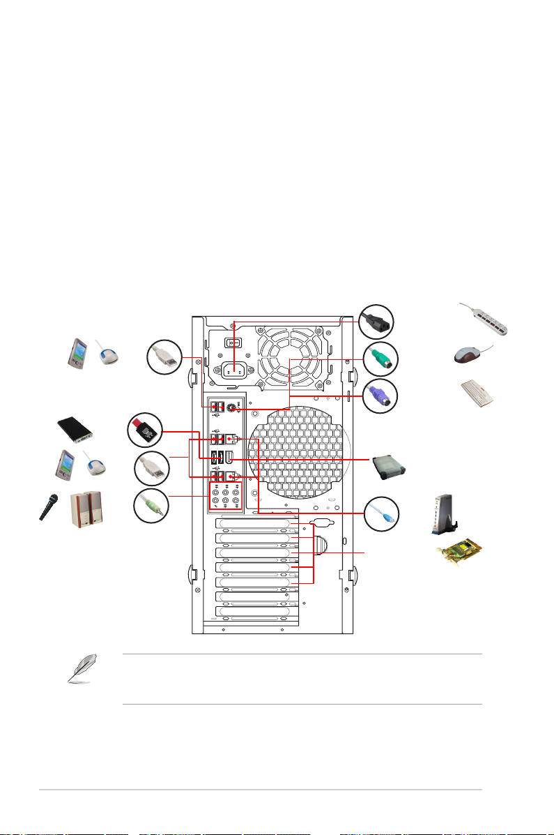
1.4 Connecting to other peripheral devices
The ASUS BA5190/AS-D900 Desktop PC is equipped with a number of ports at
the rear and front panels where you can connect peripheral devices to the system.
Refer to the illustration below for details.
Power connector
USB
PS/2 mouse
PS/2 keyboard
eSATA
USB
Audio
1394
RJ-45
Expansion slots
Before you connect a peripheral device to the system, refer to the
documentation that comes with the device or contact your supplier directly for
information on how to install it.
1-4 Chapter 1: System introduction
Page 17
Chapter 2
This chapter helps you to power up the
system and install drivers and utilities
from the Support DVD.
Getting started
Page 18
2.1 Installing an operating system
This motherboard supports Windows® XP / Vista operating systems (OS). Always
install the latest OS version and the corresponding updates to maximize the
features of your hardware. When you start the system for the rst time, the system
automatically detects the built-in audio and graphics chips and attempts to install
the drivers that come with the OS. Select NO when a window appears asking if
you want to restart the system. Install drivers according to the instructions in the
following sections.
• To ensure that the OS works properly, install the drivers included in the
Support DVD.
• Motherboard settings and hardware options vary. Use the setup
procedures presented in this chapter for reference only. Refer to your OS
documentation for detailed information.
2.2 Powering your system
Press the Power button to power up the system.
Power button
2-2 Chapter 2: Getting started
Page 19
2.3 Support DVD information
The Support DVD that comes with the system package contains the drivers,
software applications, and utilities that you can install to get all system features.
The contents of the Support DVD are subject to change at any time without
notice. Visit the ASUS website at www.asus.com for updates.
2.3.1 Running the Support DVD
Place the Support DVD into the optical drive. The DVD automatically displays the
Drivers menu if Autorun is enabled on your computer.
Click an icon to
display Support
DVD/motherboard
information
Click an item to install
If Autorun is NOT enabled on your computer, browse the contents of the
Support DVD to locate the le ASSETUP.EXE from the BIN folder. Double-click
ASSETUP.EXE to run the DVD.
ASUS BA5190/AS-D900 2-3
Page 20

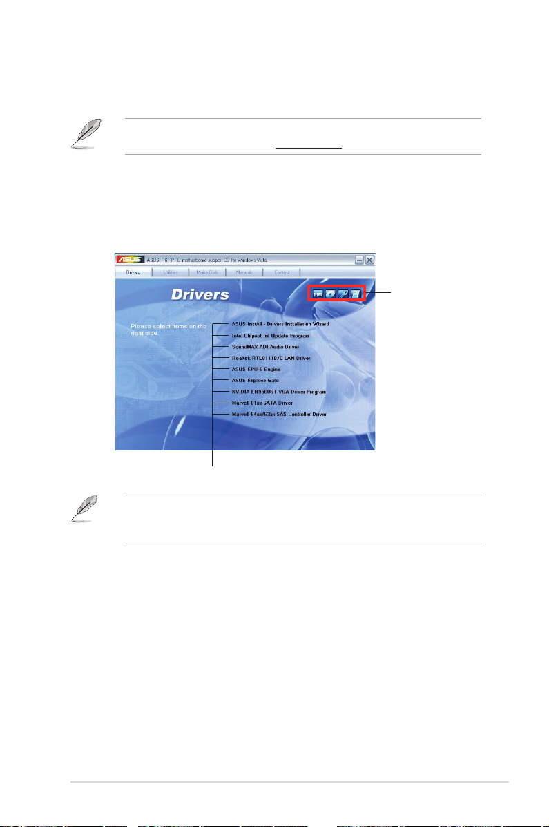
2.3.2 Drivers menu
The Drivers menu shows the available device drivers if the system detects
installed devices. Install the necessary drivers to activate the devices.
ASUS InstAll - Drivers Installation Wizard
Installs drivers for this desktop PC using the installation wizard.
Intel Chipset Inf Update Program
Installs the Intel® chipset Inf update program.
SoundMAX ADI Audio Driver
Installs the SoundMAX ADI audio driver.
Realtek RTL8111B/C LAN Driver
Installs the Realtek® RTL8111B/C LAN driver.
ASUS EPU-6 Engine
Installs ASUS EPU-6 Engine.
ASUS Express Gate
Installs ASUS Express Gate.
NVIDIA EN9500GT VGA Driver Program
Installs the NVIDIA® EN9500GT VGA driver.
Marvell 61xx SATA Driver
Installs the Marvell 61xx SATA driver.
Marvell 64xx/63xx SAS Controller Driver
Installs the Marvell 64xx/63xx SAS controller driver.
2-4 Chapter 2: Getting started
Page 21
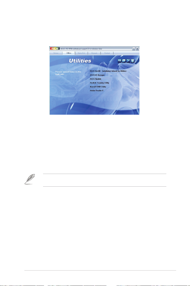
2.3.3 Utilities menu
The Utilities menu shows the applications that the system supports. Tap an item
from the screen to install.
ASUS InstAll - Installation Wizard for Utilities
Installs utilities for this desktop PC using the installation wizard.
ASUS AI Manager
Installs ASUS AI Manager where you can launch AI Disk, AI Security, and AI Probe
easily.
ASUS Update
Allows you to download the latest version of the BIOS from the ASUS website.
Before using the ASUS Update, ensure that you have an Internet connection to
connect to the ASUS website.
Realtek Teaming Utility
Installs the Realtek® Teaming Utility.
Marvell RAID Utility
Installs the Marvell RAID utility.
Adobe Reader 8
Installs the Adobe Acrobat Reader that allows you to open, view, and print
documents in Portable Document Format (PDF).
ASUS BA5190/AS-D900 2-5
Page 22

2.3.4 Make disk menu
The Make disk menu allows you to make a RAID driver disk.
Intel ICH10R 32 bit AHCI/RAID Driver
Allows you to create an Intel® ICH10R Serial ATA (SATA) AHCI/RAID driver disk for
32bit XP/Vista operating systems.
Intel ICH10R 64 bit AHCI/RAID Driver
Allows you to create an Intel® ICH10R Serial ATA (SATA) AHCI/RAID driver disk for
64bit XP/Vista operating systems.
Marvell 61xx 32/64bit SATA RAID Driver
Allows you to create a Marvell 61xx Serial ATA (SATA) RAID driver disk for 32/64bit
XP/Vista operating systems.
Marvell 64xx/63xx SAS Controller Driver
Allows you to create a Marvell 64xx/63xx SAS controller driver disk for 32/64bit
XP/Vista operating systems.
2-6 Chapter 2: Getting started
Page 23
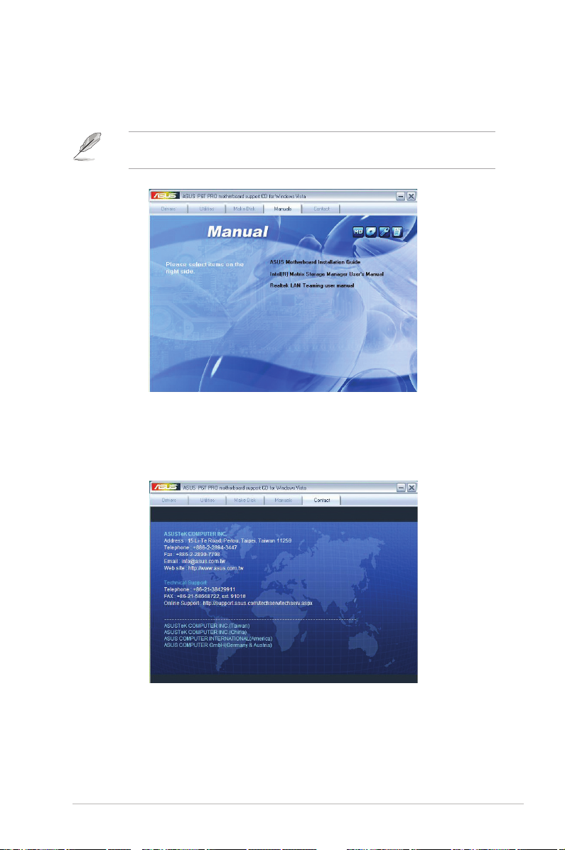
2.3.5 Manual menu
The Manual menu contains a list of supplementary user manuals. Click an item to
open the folder of the user manual.
The user manual les are in Portable Document Format (PDF). Install the
Adobe® Reader from the Utilities menu before opening a user manual le.
2.3.6 ASUS contact information
Click Contact to display the ASUS contact information.
ASUS BA5190/AS-D900 2-7
Page 24
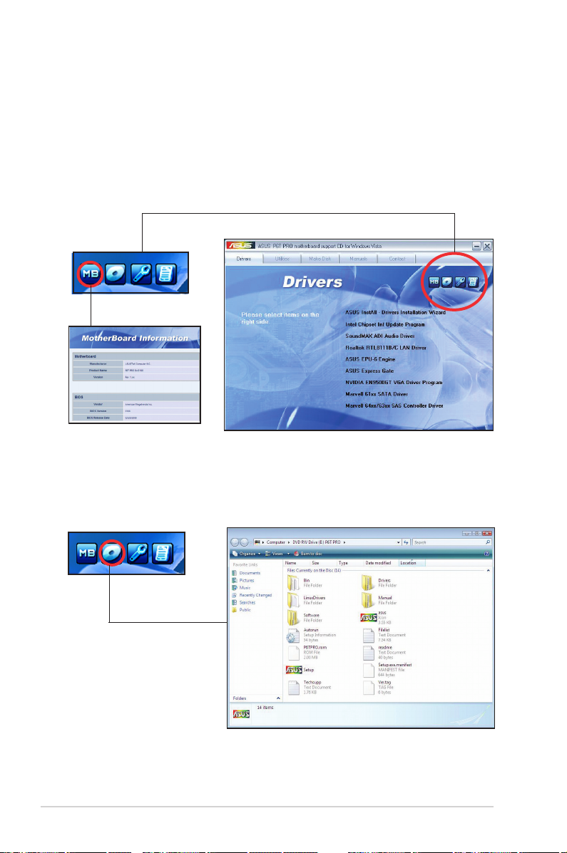
2.3.7 Other information
The icons on the top right corner of the screen give additional information on the
motherboard and the contents of the Support DVD. Click an icon to display the
specied information.
Motherboard Info
Displays the general specications of the motherboard.
Browse this DVD
Displays the Support DVD contents in graphical format.
2-8 Chapter 2: Getting started
Page 25
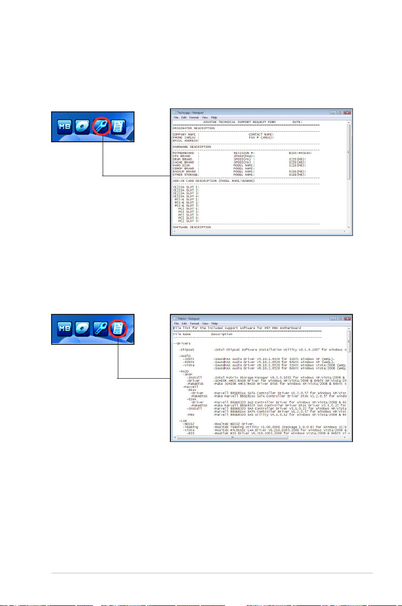
Technical support Form
Displays the ASUS Technical Support Request Form that you have to ll out when
requesting technical support.
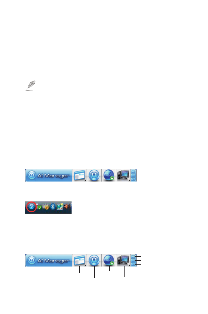
Filelist
Displays the contents of the Support DVD and a brief description of each in text
format.
ASUS BA5190/AS-D900 2-9
Page 26
2.4 ASUS AI Manager
ASUS AI Manager allows you to launch AI Disk, AI Security, and AI Probe easily.
2.4.1 Installing AI Manager
To install AI Manager on your computer:
1. Place the Support DVD into the optical drive. The DVD automatically displays
the Drivers menu if Autorun is enabled on your computer.
If Autorun is NOT enabled on your computer, browse the contents of the
Support DVD to locate the le ASSETUP.EXE from the BIN folder. Double-click
ASSETUP.EXE to run the DVD.
2. Click the Utilities tab, then click ASUS AI Manager.
3. Follow the onscreen instructions to complete the installation.
2.4.2 Launching AI Manager
You can launch AI Manager right after installation or anytime from the Windows®
desktop.
To launch AI Manager from the Windows® desktop, click Start > All Programs >
ASUS > AI Manager > AI Manager v1.xx.xx. The AI Manager Quick Bar appears.
After launching the application, the AI Manager icon appears in the Windows®
taskbar. Right-click this icon for more options.
2.4.3 AI Manager Quick Bar
Click the Main, My favorites, Support, and Information icon from the Quick Bar to
show the corresponding menu.
Close
Maximize/Restore
Minimize
Main
My Favorites
2-10 Chapter 2: Getting started
Support
Information
Page 27
Click to switch between a full-screen AI Manager window and the Quick bar.
Click to keep AI Manager in the taskbar.
Click to close AI Manager.
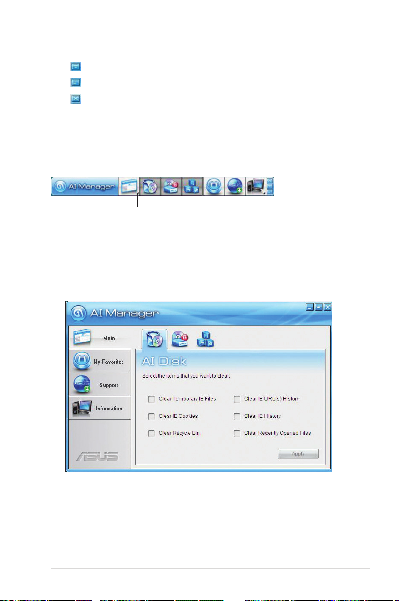
2.4.4 Main
Launch AI Disk, AI Security, and AI Probe from the Main menu. Click the small
triangle to open or close the Main menu.
Click to open/close the Main menu
AI Disk
AI Disk allows you to easily clear the temporary IE les, IE URLs, IE cookies, IE
history list, Recycle Bin, and recently opened les list. Select the item that you
want to clear, then click Apply.
ASUS BA5190/AS-D900 2-11
Page 28
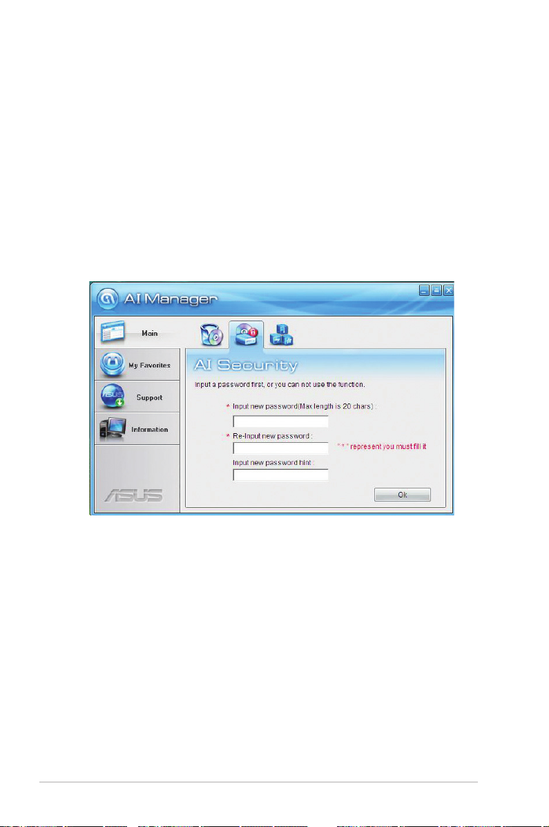
AI Security
AI Security allows you to set passwords to lock your removable storage devices
such as a USB ash disk and a CD/DVD disk, which ensures more security for
your data.
To lock a device:
1. If you are using AI Security for the rst time, key in a password consisting of
up to 20 alphanumeric characters.
2 Conrm your password.
3. Key in your password hint (optional).
4. Click OK.
2-12 Chapter 2: Getting started
Page 29
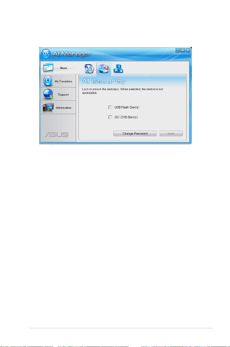
5. Select the device you want to lock, then click Apply.
6. Key in your password, then click OK. The device you selected cannot be
accessed without the password.
To unlock a device:
1. Deselect the device you locked, then click Apply.
2. Key in your password, then click OK.
To change your password, click Change Password and follow the onscreen
instructions.
ASUS BA5190/AS-D900 2-13
Page 30
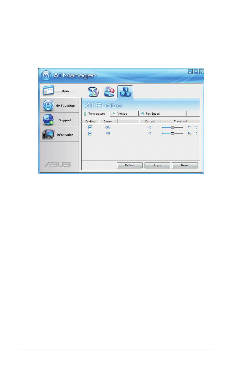
AI Probe
AI Probe automatically detects the motherboard and CPU temperatures, CPU fan
speed, and CPU voltage. It also allows you to adjust these values manually.
2-14 Chapter 2: Getting started
Page 31

2.4.5 My favorites
Add your favorite applications to the My Favorites menu.
To add an application:
1. Click Add and then from the succeeding screen select the application you
want to add to the My Favorites menu.
2. Click Open. The application you selected is added and its icon appears.
Right-click an icon in the My Favorites menu to open, delete, or rename the
corresponding application.
Double-click an icon to open the corresponding application.
ASUS BA5190/AS-D900 2-15
Page 32

2.4.6 Support
The Support menu displays links to the ASUS international website, online
technical support website, online download support website, and contact
information website.
2.4.7 Information
The Information menu displays the general information of your system,
motherboard, CPU, BIOS, memory, and other devices installed.
2-16 Chapter 2: Getting started
Page 33

2.5 ASUS MyLogo 2™
ASUS MyLogo 2™ allows you to customize the boot logo. The boot logo is the
image that appears on the screen during the Power-On Self-Test (POST). ASUS
MyLogo 2 is automatically installed when you install the ASUS Update utility from
the Support DVD. See 2.3.3 Utilities menu for details.
• Before using ASUS MyLogo 2, use the ASUS Update or AFUDOS utilities
to make a copy of your original BIOS le or obtain the latest BIOS version
from the ASUS website.
• Set the Full Screen Logo item in the BIOS to [Enabled] before using ASUS
MyLogo 2.
• You can create your own boot logo image in GIF le format.
To launch ASUS MyLogo 2:
1. Launch the ASUS Update utility.
2. Select Options from the drop-down menu, and then click Next.
3. Check Launch MyLogo to replace the system boot logo before ashing
BIOS, and then click Next.
4. Select UpdateBIOSfromale from the drop-down menu, and then click
Next.
5. Locate the new BIOS le, and then click Next. The ASUS MyLogo 2 window
appears.
6. From the left window pane, select the folder that contains the image you
intend to use as your boot logo.
ASUS BA5190/AS-D900 2-17
Page 34

7. When the logo images appear on the
right window pane, select an image to
enlarge by clicking on it.
8. Adjust the boot image to your desired
size by selecting a value on the Ratio
box. Click Next.
9. When the screen returns to the ASUS Update utility, ash the BIOS to load
the new boot logo.
10. After ashing the BIOS, restart the computer to display the new boot logo
during POST.
2-18 Chapter 2: Getting started
Page 35

2.6 ASUS EPU–6 Engine
ASUS EPU–6 Engine is an energy-efcient tool that satises different computing
needs. This utility provides four modes that you can select to enhance system
performance or save power. Selecting Auto mode will have the system shift modes
automatically according to current system status. You can also customize each
mode by conguring settings like CPU frequency, vCore Voltage, and Fan Control.
Installing 6 Engine
To install 6 Engine on your computer:
1. Place the Support DVD into the optical drive. The Drivers menu appears if
Autorun is enabled on your computer.
2. Click the Drivers tab and then click ASUS EPU—6 Engine.
3. Follow the onscreen instructions to complete the installation.
Launching 6 Engine
Launch 6 Engine by double-clicking the 6 Engine icon in the Windows
tray.
The rst time you launch 6 Engine, the
following message appears, asking
you to run Calibration rst. Running
calibration allows the system to
detect CPU properties to optimize
power management.
Click Run Calibration and wait for
a few seconds. Then, the 6 Engine
main menu appears.
®
system
ASUS BA5190/AS-D900 2-19
Page 36

6 Engine main menu
Displays the following
message if no VGA power
saving engine is detected.
Displays
current
mode
Displays CPU Power and
Total CPU Energy Saving
Lights up when power
saving engine is activated
Displays the
amount of CO2
reduced
*Shifts between
the display of Total
and Current CO2
reduced
Auto Mode
Turbo Mode
High Performance Mode
Medium Power Saving Mode
Max. Power Saving Mode
Advanced settings for each mode (refer to the next page for further information)
Runs calibration
Displays the system
properties of each
mode
Exits the utility
• Click Current to show the CO2 that has been reduced since
you click the Renew button .
• Click Total to show the total CO2 that has been reduced
since you launched 6 Engine.
2-20 Chapter 2: Getting started
Page 37

Advanced settings menu
Click Setting from the 6 Engine main menu to display conguration
options in each mode. Some options in certain modes are dimmed, meaning that
they are not available.
Click to select
a mode
Move the
slider to adjust
Click the arrow
to see more
options
Restore default
settings
Click to apply
settings
Click to abort
settings
CongurationoptionsinAdvancedsettingsmenu
The following lists the conguration options and their denitions in Advanced
settings menu.
• CPU Frequency: Raises or lowers CPU frequency to a certain percentage.
• vCore Voltage Downgrade: Lowers CPU vCore voltage.
• High: Downgrades voltage to the highest level for CPU power saving.
• Small: Downgrades voltage to the minimum level.
• Chipset Voltage Downgrade: Turns on/off chipset voltage.
• Turn Off hard disks: Turns off hard disk drives when they are not accessed
after a certain time.
• CPU Loadline: Sets up the CPU loadline to manage CPU power saving.
• Light: Saves CPU power to the minimum level.
• Heavy: Saves CPU power to the highest level.
ASUS BA5190/AS-D900 2-21
Page 38

• Fan Control: Adjusts fan speeds to reduce noise and save system power.
• Quiet: Lowers CPU fan speed and shuts off two chassis fans.
• Slow: Lowers CPU fan and two chassis fan speeds.
• AI Nap Idle Time: Enters AI Nap mode after a certain time during system idle
process.
Refer to the following table for the conguration options in each mode.
Conguration
options
CPU
Frequency
vCore Voltage
Downgrade
Chipset
Voltage
Downgrade
Turn Off
hard disks
CPU Loadline N/A N/A Light/Heavy Light/Heavy
Fan Control N/A N/A Keep Bios
AI Nap
Idle Time
Turbo Mode High
Overclocking
+1% to +5%
N/A N/A Small/High Small/High
N/A N/A On/Off On/Off
Never/After 3
mins–After 5
hours
Never/After 3
mins–After 5
hours
The values in the table above are subject to change at any time without notice.
Visit the ASUS website at www.asus.com for updates.
Performance
Mode
N/A Downclocking
Never/After 3
mins–After 5
hours
Never/After 3
mins–After 5
hours
Medium Power
Saving Mode
-1% to -10%
Never/After 3
mins–After 5
hours
Setting/Slow
Never/After 3
mins–After 5
hours
Maximum
Power Saving
Mode
Downclocking
-1% to -10%
Never/After 3
mins–After 5
hours
Keep Bios
Setting/Quiet
Never/After 3
mins–After 5
hours
2-22 Chapter 2: Getting started
Page 39

2.7 ASUS Express Gate
ASUS Express Gate is an instant-on environment that gives you quick access to
the Internet. Five seconds after powering on your computer, you can instantly surf
the Internet, use Skype or other Express Gate applications.
Download the latest Express Gate version from the ASUS website at www.asus.
com.
Installing ASUS Express Gate
• Ensure to install ASUS Express Gate from the motherboard Support DVD
before use.
• ASUS Express Gate supports installation on SATA HDDs, USB HDDs, and
Flash drives. When installing ASUS Express Gate on USB HDDs and Flash
drives, connect the drives to the motherboard USB port before turning on
the computer.
• ASUS Express Gate supports SATA devices in IDE mode only.
• ASUS Express Gate supports SATA devices connected to motherboard
chipset-controlled onboard SATA ports only. All onboard extended SATA
ports and external SATA ports are NOT supported.
• ASUS Express Gate supports a screen resolution of 1024 x 768 only.
Ensure to set your screen resolution to 1024 x 768 before using ASUS
Express Gate; otherwise, it will not launch after bootup and your computer
boots to the OS directly.
To install Express Gate on your computer:
1. Place the Support DVD into the optical drive. The Drivers menu appears if
Autorun is enabled on your computer.
2. Click the Utilities tab, then click ASUS Express Gate.
3. Select your preferred language, then click OK.
4. The InstallShield Wizard for Express Gate appears. Click Next to continue.
5. Select the target drive where you want to install Express Gate. If you have
multiple partitions installed on your computer, it is recommended to install
Express Gate in Drive C. Click Next to continue.
6. Follow the onscreen instructions to complete the installation.
ASUS BA5190/AS-D900 2-23
Page 40

The Splash Screen
The Express Gate’s splash screen appears within a few seconds after bootup.
Click an application icon
to enter the Express Gate
environment and launch the
selected application
Turn off the computer
Enter the BIOS Setup program
Continue booting to the existing OS when the timer counts down to
zero (0); click to immediately enter the existing OS
Splash screen hot keys
Key Function
<PAUSE/BREAK> Power off
<ESC> / <F8> Continue to boot OS
<DEL> Enter BIOS setup
The Express Gate’s splash screen supports a screen resolution of 1024 x 768
only.
Express Gate hot keys
Key Function
<Alt> + <Tab> Switch between applications
<Ctrl> + <Alt> + <Del> Bring the Power-Off dialog box
<Ctrl> + <Alt> + <Print Screen> Save screen snapshots
2-24 Chapter 2: Getting started
Page 41

Using the LaunchBar
Click an icon on the LaunchBar to launch the corresponding application.
Launches the Web Browser for quick access to the Internet.
Launches the Online Games.
Launches the Photo Manager album / organizer tool.
Launches the Chat instant messaging tool.
Launches the Skype application which allows you to chat with or call
other people on Skype.
Launches the CongurationPanel which allows you to specify network
settings and other settings.
If an application stops responding, right-click its icon then select Close to force
it to close.
The smaller icons on the right side of the LaunchBar are:
Launches File Manager which allows you to access les on a USB
drive. If a USB device is detected, the icon contains a green arrow.
ASUS Express Gate supports le uploading from SATA HDDs, ODDs, and USB
drives. It supports le downloading to USB drives only.
Congures the network.
Adjusts the volume.
ASUS BA5190/AS-D900 2-25
Page 42

Sets the input language and keyboard shortcuts (Ctrl-Space by default).
Congures the LaunchBar settings such as auto-hide mode and docking
position.
Displays the ASUS Utility Panel (if supported).
Displays your Express Gate version.
Launches the help le.
Launches the Power Off window where you may choose to enter OS,
restart the computer, or power off the computer. This window also
appears when you press <Ctrl> + <Alt> + <Del> on the keyboard.
Power off
Enter OS
Check to save
userprole
Cancel and return to
Express Gate
Accessing the Internet
To congure the network settings:
1. Click CongurationPanel on the
LaunchBar.
2. Click Network.
3. Make the proper network
congurations. Each network interface
is enabled immediately after you tick
the Enable checkbox.
The number of the LAN ports vary with the motherboard.
Restart
2-26 Chapter 2: Getting started
Page 43

• LAN settings
If you use a network cable connected to a home router that is connected
to your DSL/cable modem, enable all the LAN ports. Express Gate
automatically uses the available port.
If you plug the network cable into a different port while Express Gate is running
(e.g. move the cable from LAN1 to LAN2, restart Express Gate to activate the
new setting.
If your computer does not automatically get network settings from a DHCP
server, click Setup to congure the static IP settings manually. If your
computer automatically gets network settings from a DHCP server, skip this
step.
• WiFi settings (if supported)
If you want to connect to a wireless network, click Setup to congure the
WiFi options. In the WiFi tab of the Advanced Network Settings box, key in
the network name of the wireless access point in the SSID eld. If Security
is enabled on the wireless access point, select the corresponding security
algorithm from the dropdown list such as WEP or WAP in the Encryption
Type eld, and key in the password. Click OK to enable WiFi and establish
the wireless connection.
• xDSL / Cable dial-up (PPPoE) settings:
If you use a network cable connected directly to your DSL/cable modem,
click Setup to congure the xDSL/cable dial-up settings. Choose whether
the DSL/cable modem is connected to your computer’s LAN port. Key in the
username and password for your account. Click OK to enable xDSL/cable
dial-up and establish the PPPoE connection. When PPPoE is enabled, the
port it uses will automatically be unchecked.
ASUS BA5190/AS-D900 2-27
Page 44

Using the Online Games
Express Gate introduces a Splashtop Gaming portal site which provides
interesting games in different categories.
Enable the Internet connection to use the Online Games feature.
See the latest
games
See the most
popular games
Search a game
See games in
different categories
Game list
Using the Photo Manager
Photo Manager allows you to view pictures saved on your hard drive or external
storage devices. You can view pictures in thumbnail view, in an enlarged
view individually, in a lename/data list view, or play them in a slideshow with
background music and fancy transition effects. JPEG, GIF, BMP, and PNG formats
are supported. Refer to the online Help for details.
HelpPhoto slideshow
View mode
selection
Shows the image
folders found on
your hard drive or
external devices
Shows user-created
image albums
Image
control bar
ASUS Express Gate supports SATA devices connected to motherboard
chipset-controlled onboard SATA ports only. All onboard extended SATA
ports and external SATA ports are NOT supported.
2-28 Chapter 2: Getting started
Page 45

Restoring to factory settings
To restore Express Gate to the factory settings:
1. Click CongurationPanel on the LaunchBar.
2. Click Environment Settings.
3. Click Restore from the General tab. A conrmation dialog box appears. Click
Yes to immediately restart Express Gate to nish clearing system settings. All
bookmarks, network settings, and other changes you made will be cleared.
The rst-time Wizard will run again when you enter the Express Gate
environment after clearing its settings.
ConguringExpressGateinBIOSSetup
To enter the BIOS Setup program, press <DEL> during POST or click the BIOS
Setup button on the Express Gate’s splash screen. Go to the Tools menu to
congure Express Gate.
Main Advanced Power Boot Tools Exit
ASUS EZ Flash 2
Express Gate [Enabled]
Enter OS Timer [10 Seconds]
Reset User Data [No]
BIOS SETUP UTILITY
Press ENTER to run
the utility to select
and update BIOS.
This utility doesn't
support :
1.NTFS format
ASUS BA5190/AS-D900 2-29
Page 46

Updating Express Gate
To update Express Gate:
1. Double-click the Express Gate setup
le to start the software update.
2. A software update conrmation
dialog box appears. Click Yes to
continue.
3. The InstallShield Wizard for Express Gate appears. Click Next to continue.
4. Follow the onscreen instructions to complete the updating process.
Download the latest Express Gate version from the ASUS website at www.asus.
com.
Repairing Express Gate
In case Express Gate does not start
normally, reinstall the software or use the
repair utility to repair Express Gate.
To repair Express Gate:
• Click Start > All Programs >
Express Gate > Express Gate
Installer > Repair this software.
• You may also double-click the
Express Gate setup le, choose
Repair, and click Next to continue.
2-30 Chapter 2: Getting started
Page 47

2.8 Realtek Teaming Utility
This motherboard features two Realtek® 8111C PCIe Gigabit LAN controllers and
supports Teaming function, which allows two single connections to be grouped
as one single connection, providing benets such as bandwidth increase, load
balancing, and fault tolerance.
The speed of transmission is subject to the actual network environment or
status even with Teaming enabled.
To install Realtek Teaming Utility:
1. Place the support DVD into the optical drive. Click Realtek Teaming Utility
from the Utilities tab.
2. Follow the onscreen instructions to complete the installation.
ConguringRealtekTeamingUtilityinWindows® XP
To create a teaming set in Windows® XP:
1. Launch the Realtek Teaming Utility by clicking Start > All Programs >
Realtek > Teaming Utility > Teaming Utility.
2. Select a LAN adapter from the
left column, select Teaming in
the middle column, and then click
Create Team.
3. Enter a name for the teaming in
the Team Name box. Select a
teaming mode that best suits your
network environment, and then
choose the adapters to join the
teaming set. Click OK to nish the
teaming setting.
ASUS BA5190/AS-D900 2-31
Page 48

To remove a teaming set in Windows® XP:
1. Launch the Realtek Teaming Utility.
2. Select the teaming set that you want
to remove in the left column, select
the virtual adapter in the right column,
and then click Remove.
ConguringRealtekTeamingUtilityinWindows® Vista
To create a teaming set in Windows® Vista:
1. Launch the Realtek VLAN & Teaming Utility by clicking Start > All Programs
> Realtek Teaming and VLAN Utility > Realtek Teaming and VLAN Utility.
2. Choose the adapters to join the
teaming set, and then select a
teaming mode that best suits
your network environment. Click
Teaming to create the teaming
set. Click OK to close the message
windows and nish creating the
teaming set.
To remove a teaming set in Windows® Vista:
1. Launch the Realtek VLAN &
Teaming Utility.
2. Click Remove to remove the
existing teaming set.
2-32 Chapter 2: Getting started
Page 49

To create a virtual LAN adapter in Windows® Vista:
1. Launch the Realtek VLAN &
Teaming Utility.
2. Choose one adapter to create
the virtual LAN adapter, and then
click VLAN. Click OK to close the
message window and nish creating
the virtual LAN adapter.
3. Click Start > Control Panel >
Network and Sharing Center,
and then click Manage network
connections from the left Tasks
list.
Right-click the virtual LAN adapter
icon and select Properties.
4. Conduct necessary settings for the
virtual LAN adapter, and then click
Congure.
ASUS BA5190/AS-D900 2-33
Page 50

5. Click the Advanced tab in the
Realtek Virtual Miniport Driver
for VLAN (NDIS 6.0) Properties
window and conduct necessary
VLAN settings. Close all windows
when nished.
To remove a virtual LAN adapter in Windows® Vista:
1. Launch the Realtek VLAN &
Teaming Utility.
2. Click Remove to remove the
existing virtual LAN adapter.
2-34 Chapter 2: Getting started
Page 51

2.9 RAIDcongurations
The motherboard comes with the Intel® ICH10R Southbridge controller that
supports RAID 0, RAID 1, RAID 10, and RAID 5 for six independent Serial ATA
channels.
2.9.1 RAIDdenitions
RAID 0 (Data striping) optimizes two identical hard disk drives to read and write
data in parallel, interleaved stacks. Two hard disks perform the same work as a
single drive but at a sustained data transfer rate, double that of a single disk alone,
thus improving data access and storage. Use of two new identical hard disk drives
is required for this setup.
RAID 1 (Data mirroring) copies and maintains an identical image of data from
one drive to a second drive. If one drive fails, the disk array management software
directs all applications to the surviving drive as it contains a complete copy of
the data in the other drive. This RAID conguration provides data protection and
increases fault tolerance to the entire system. Use two new drives or use an
existing drive and a new drive for this setup. The new drive must be of the same
size or larger than the existing drive.
RAID 5 stripes both data and parity information across three or more hard
disk drives. Among the advantages of RAID 5 conguration include better
HDD performance, fault tolerance, and higher storage capacity. The RAID
5 conguration is best suited for transaction processing, relational database
applications, enterprise resource planning, and other business systems. Use a
minimum of three identical hard disk drives for this setup.
RAID 10 is data striping and data mirroring combined without parity (redundancy
data) having to be calculated and written. With the RAID 10* conguration you get
all the benets of both RAID 0 and RAID 1 congurations. Use four new hard disk
drives or use an existing drive and three new drives for this setup.
Intel® Matrix Storage. The Intel® Matrix Storage technology supported by the
ICH10R chip allows you to create a RAID 0, RAID 1, RAID 5, and RAID 10*
function to improve both system performance and data safety. You can also
combine two RAID sets to get higher performance, capacity, or fault tolerance
provided by the difference RAID function. For example, RAID 0 and RAID 1 set
can be created by using only two identical hard disk drives.
If you want to boot the system from a hard disk drive included in a created RAID
set, copy the RAID driver from the support DVD to a oppy disk before you
install an operating system to the selected hard disk drive. Refer to section 2.10
Creating a RAID driver disk for details.
ASUS BA5190/AS-D900 2-35
Page 52

2.9.2 Installing Serial ATA hard disks
The motherboard supports Serial ATA hard disk drives. For optimal performance,
install identical drives of the same model and capacity when creating a disk array.
To install the SATA hard disks for a RAID conguration:
1. Install the SATA hard disks into the drive bays.
2. Connect the SATA signal cables.
3. Connect a SATA power cable to the power connector on each drive.
2.9.3 Intel®RAIDcongurations
This motherboard supports RAID 0, RAID 1, RAID 5, RAID 10 and Intel
Storage congurations for Serial ATA hard disks drives through the Intel® ICH10R
Southbridge chip.
Setting the RAID item in BIOS
You must set the RAID item in the BIOS Setup before you can create a RAID
set(s). To do this:
1. Enter the BIOS Setup during POST.
2. Go to Main>StorageConguration>CongureSATAas, then press
<Enter>.
3. Select [RAID], then press <Enter>.
5. Save your changes, then exit the BIOS Setup.
®
Matrix
2-36 Chapter 2: Getting started
Page 53

Intel® Matrix Storage Manager option ROM utility
The Intel® Matrix Storage Manager Option ROM utility allows you to create RAID 0,
RAID 1, RAID 10 (RAID 0+1), and RAID 5 set(s) from Serial ATA hard disk drives
that are connected to the Serial ATA connectors supported by the Southbridge.
To enter the Intel® Matrix Storage Manager option ROM utility:
1. Install all the Serial ATA hard disk drives.
2. Turn on the system.
3. During POST, press <Ctrl+I> to display the utility main menu.
Intel(R) Matrix Storage Manager Option ROM v8.0.0.1027 ICH10R wRAID5
Copyright(C) 2003-08 Intel Corporation. All Rights Reserved.
1. Create RAID Volume 3. Reset Disks to Non-RAID
2. Delete RAID Volume 4. Exit
[ MAIN MENU ]
RAID Volumes:
None dened.
Physical Disks:
Port Drive Model Serial # Size Type/Status(Vol ID)
0 XXXXXXXXXXX XXXXXXXX XX.XXGB Non-RAID Disk
1 XXXXXXXXXXX XXXXXXXX XX.XXGB Non-RAID Disk
2 XXXXXXXXXXX XXXXXXXX XX.XXGB Non-RAID Disk
3 XXXXXXXXXXX XXXXXXXX XX.XXGB Non-RAID Disk
[↑↓]-Select [ESC]-Exit [ENTER]-Select Menu
[ DISK/VOLUME INFORMATION ]
The navigation keys at the bottom of the screen allow you to move through
the menus and select the menu options.
The RAID BIOS setup screens shown in this section are for reference only and
may not exactly match the items on your screen.
ASUS BA5190/AS-D900 2-37
Page 54

Creating a RAID 0 set (striped)
To create a RAID 0 set:
1. From the utility main menu, select 1. Create RAID Volume and press
<Enter>. The following screen appears.
Intel(R) Matrix Storage Manager option ROM v8.0.0.1027 ICH10R wRAID5
Copyright(C) 2003-08 Intel Corporation. All Rights Reserved.
[ CREATE VOLUME MENU ]
Name:
RAID Level:
Disks:
Strip Size:
Capacity:
Volume0
RAID0(Stripe)
Select Disks
128KB
XXX GB
Create Volume
[ HELP ]
Enter a unique volume name that has no special characters and is
[↑↓]-Change [TAB]-Next [ESC]-Previous Menu [Enter]-Select
16 characters or less.
2. Enter a name for the RAID 0 set and press <Enter>.
3. When the RAID Level item is highlighted, press the up/down arrow key to
select RAID 0(Stripe), and then press <Enter>.
4. When the Disks item is highlighted, press <Enter> to select the hard disk
drives to congure as RAID. The following screen appears.
[ SELECT DISKS ]
Port Drive Model Serial # Size Status
0 XXXXXXXXXXXX XXXXXXXX XX.XGB Non-RAID Disk
1 XXXXXXXXXXXX XXXXXXXX XX.XGB Non-RAID Disk
2 XXXXXXXXXXXX XXXXXXXX XX.XGB Non-RAID Disk
3 XXXXXXXXXXXX XXXXXXXX XX.XGB Non-RAID Disk
Select 2 to 6 disks to use in creating the volume.
[↑↓]-Previous/Next [SPACE]-SelectsDisk [ENTER]-Done
5. Use the up/down arrow key to highlight a drive, and then press <Space>
to select. A small triangle marks the selected drive. Press <Enter> after
completing your selection.
2-38 Chapter 2: Getting started
Page 55

6. Use the up/down arrow key to select the stripe size for the RAID 0 array, and
then press <Enter>. The available stripe size values range from 4 KB to 128
KB. The default stripe size is 128 KB.
We recommend a lower stripe size for server systems, and a higher stripe size
for multimedia computer systems used mainly for audio and video editing.
7. Enter the RAID volume capacity that you want and press <Enter>. The
default value indicates the maximum capacity allowed.
8. Press <Enter> when the Create Volume item is highlighted. The following
warning message appears.
WARNING: ALL DATA ON SELECTED DISKS WILL BE LOST.
Are you sure you want to create this volume? (Y/N):
9. Press <Y> to create the RAID volume and return to the main menu, or <N> to
go back to the Create Volume menu.
ASUS BA5190/AS-D900 2-39
Page 56

Creating a RAID 1 set (mirrored)
To create a RAID 1 set:
1. From the utility main menu, select 1. Create RAID Volume and press
<Enter>. The following screen appears.
Intel(R) Matrix Storage Manager option ROM v8.0.0.1027 ICH10R wRAID5
Copyright(C) 2003-08 Intel Corporation. All Rights Reserved.
[ CREATE VOLUME MENU ]
Name:
RAID Level:
Disks:
Strip Size:
Capacity:
Volume1
RAID1(Mirror)
Select Disks
N/A
XXX GB
Create Volume
[ HELP ]
Enter a unique volume name that has no special characters and is
[↑↓]-Change [TAB]-Next [ESC]-Previous Menu [Enter]-Select
16 characters or less.
2. Enter a name for the RAID 1 set and press <Enter>.
3. When the RAID Level item is highlighted, press the up/down arrow key to
select RAID 1(Mirror), then press <Enter>.
4. When the Capacity item is highlighted, enter the RAID volume capacity that
you want, and then press <Enter>. The default value indicates the maximum
capacity allowed.
5. Press <Enter> when the Create Volume item is highlighted. The following
warning message appears.
WARNING: ALL DATA ON SELECTED DISKS WILL BE LOST.
Are you sure you want to create this volume? (Y/N):
6. Press <Y> to create the RAID volume and return to main menu or <N> to go
back to Create Volume menu.
2-40 Chapter 2: Getting started
Page 57

Creating a RAID 10 set (RAID 0+1)
To create a RAID 10 set:
1. From the utility main menu, select 1. Create RAID Volume and press
<Enter>. The following screen appears.
Intel(R) Matrix Storage Manager option ROM v8.0.0.1027 ICH10R wRAID5
Copyright(C) 2003-08 Intel Corporation. All Rights Reserved.
[ CREATE VOLUME MENU ]
Name:
RAID Level:
Disks:
Strip Size:
Capacity:
Volume10
RAID10(RAID0+1)
Select Disks
64KB
XXX GB
Create Volume
[ HELP ]
Enter a unique volume name that has no special characters and is
[↑↓]-Change [TAB]-Next [ESC]-Previous Menu [Enter]-Select
16 characters or less.
2. Enter a name for the RAID 10 set and press <Enter>.
3. When the RAID Level item is highlighted, press the up/down arrow key to
select RAID 10 (RAID 0+1), and then press <Enter>.
4. When the Stripe Size item is highlighted, press the up/down arrow key to
select the stripe size for the RAID 10 array, and then press <Enter>. The
available stripe size values range from 4 KB to 64 KB. The default stripe size
is 64 KB.
We recommend a lower stripe size for server systems, and a higher stripe size
for multimedia computer systems used mainly for audio and video editing.
5. Enter the RAID volume capacity that you want and press <Enter>. The
default value indicates the maximum capacity allowed.
ASUS BA5190/AS-D900 2-41
Page 58

6. Press <Enter> when the Create Volume item is highlighted. The following
warning message appears.
WARNING: ALL DATA ON SELECTED DISKS WILL BE LOST.
Are you sure you want to create this volume? (Y/N):
7. Press <Y> to create the RAID volume and return to the main menu or <N> to
go back to the Create Volume menu.
Creating a RAID 5 set (parity)
To create a RAID 5 set:
1. From the utility main menu, select 1. Create RAID Volume and press
<Enter>. The following screen appears.
Intel(R) Matrix Storage Manager option ROM v8.0.0.1027 ICH10R wRAID5
Copyright(C) 2003-08 Intel Corporation. All Rights Reserved.
[ CREATE VOLUME MENU ]
Name:
RAID Level:
Disks:
Strip Size:
Capacity:
Volume5
RAID5(Parity)
Select Disks
64KB
XXX GB
Create Volume
[ HELP ]
Enter a unique volume name that has no special characters and is
[↑↓]-Change [TAB]-Next [ESC]-Previous Menu [Enter]-Select
16 characters or less.
2. Enter a name for the RAID 5 set and press <Enter>.
3. When the RAID Level item is highlighted, press the up/down arrow key to
select RAID 5(Parity), and then press <Enter>.
2-42 Chapter 2: Getting started
Page 59

4. The Disks item is highlighted, press <Enter> to select the hard disk drives to
congure as RAID. The following screen appears.
[ SELECT DISKS ]
Port Drive Model Serial # Size Status
0 XXXXXXXXXXXX XXXXXXXX XX.XGB Non-RAID Disk
1 XXXXXXXXXXXX XXXXXXXX XX.XGB Non-RAID Disk
2 XXXXXXXXXXXX XXXXXXXX XX.XGB Non-RAID Disk
3 XXXXXXXXXXXX XXXXXXXX XX.XGB Non-RAID Disk
Select 3 to 6 disks to use in creating the volume.
[↑↓]-Previous/Next [SPACE]-SelectsDisk [ENTER]-Done
5. Use the up/down arrow key to highlight the drive you want to set, and then
press <Space> to select. A small triangle marks the selected drive. Press
<Enter> after completing your selection.
6. When the Stripe Size item is highlighted, press the up/down arrow key to
select the stripe size for the RAID 5 array, and then press <Enter>. The
available stripe size values range from 16 KB to 128 KB. The default stripe
size is 64 KB.
We recommend a lower stripe size for server systems, and a higher stripe size
for multimedia computer systems used mainly for audio and video editing.
7. Enter the RAID volume capacity that you want and then press <Enter>. The
default value indicates the maximum allowed capacity.
8. Press <Enter> when the Create Volume item is highlighted. The following
warning message appears.
WARNING: ALL DATA ON SELECTED DISKS WILL BE LOST.
Are you sure you want to create this volume? (Y/N):
9. Press <Y> to create the RAID volume and return to the main menu or <N> to
go back to the Create Volume menu.
ASUS BA5190/AS-D900 2-43
Page 60

2.9.4 Marvell®SASRAIDcongurations
The Marvell® 88SE6320 SAS controller allows you to congure RAID 0 and 1 set
on the SAS hard disk drives.
Setting the RAID item in BIOS
You must set the RAID item in the BIOS Setup before you can create a RAID set.
To do this:
1. Install two internal SAS hard disk drives to the SAS connectors labeled
SAS1/2.
2. Boot up your computer, and press <Del> during POST to enter the BIOS
setup.
3. In the Advanced menu, go to OnboardDevicesConguration, and enable
both Marvell SAS and SAS Boot ROM.
4. Press <F10> to save the changes and exit.
Advanced
Onboard Devices Conguration
High Denition Audio [Enabled]
Front Panel Type [HD Audio]
Marvell Storage Controller [Enabled]
Marvell Storage Boot Rom [Enabled]
Marvell SAS [Enabled]
SAS Boot ROM [Enabled]
Marvell LAN1 [Enabled]
Marvell LAN2 [Enabled]
LAN Boot ROM [Disabled]
Onboard 1394 Controller [Enabled]
v02.61 (C)Copyright 1985-2008, American Megatrends, Inc.
BIOS SETUP UTILITY
Enable or Disable
High Denition Audio
Controller
Select Screen
Select Item
+- Change Option
F1 General Help
F10 Save and Exit
ESC Exit
The RAID BIOS setup screens shown in this section are for reference only, and
may not exactly match the items on your screen.
2-44 Chapter 2: Getting started
Page 61

Marvell®RAIDBIOSCongurationutility
To enter the Marvell® RAID BIOS setup utility
1. Boot up your computer.
2. During POST, press <Ctrl> + <M> to enter the utility main menu.
Marvell BIOS Setup (c) 2007 Marvell Technology Group Ltd.
[Selection] [Controller] [ Devices ] [ RAID ]
Adapter 1
VendorID:DeviceID: 11AB:6320
BIOS Version: 2.1.0.09
PCI Slot: 00
Adapter Serial Number: FFFFFFFFFFFFFFFFFFFF
IRQ Number: 0A
Port 0 SAS Address: 500E018000000000
Port 1 SAS Address: 5005018000000001
Port 2 SAS Address: 5005043011AB0000
Port 3 SAS Address: 5005043011AB0000
ENTER/SPACE:Select, ESC:Back/Exit
3. Press <Enter> and select a desired adapter for RAID conguration.
Marvell BIOS Setup (c) 2007 Marvell Technology Group Ltd.
[Selection] [Controller] [ Devices ] [ RAID ]
Select Adapter
Adapter 1
ENTER/SPACE:Select, ESC:Back/Exit
ASUS BA5190/AS-D900 2-45
Page 62

Creating a RAID 0 or RAID 1 set
To create a RAID set:
1. From the utility menu bar, select RAID > Create array.
Marvell BIOS Setup (c) 2007 Marvell Technology Group Ltd.
[Selection]
ENTER/SPACE:Select, ESC:Back/Exit
2. Press <Enter>. The screen shows the disks you can add to make up the
RAID set. Use the arrow key to select a disk and press <Enter> or <Space>
to include this disk in the array.
Marvell BIOS Setup (c) 2007 Marvell Technology Group Ltd.
[Selection] [Controller] [ Devices ] [ RAID ]
Select free disks to create
ID Port Disk Name Size Max Speed Status
0 0 SAS : ST336754SS 36.6GB SAS 3.0 FREE
1 1 SAS : ST336754SS 36.6GB SAS 3.0 FREE
NEXT
[Controller] [ Devices ] [ RAID ]
RAID Cong
Create array
Delete array
Spare Management
RAID Cong
ENTER/SPACE:Select, ESC:Back/Exit
3. After you have selected the desired disks, select NEXT to create array.
2-46 Chapter 2: Getting started
Page 63

4. The Create Array screen appears.
Marvell BIOS Setup (c) 2007 Marvell Technology Group Ltd.
[Selection] [Controller] [ Devices ] [ RAID ]
Select free disks to create
Create Array
ID Port Disk Name Size Max Speed Status
Raid Level : RAID0
*0 0 SAS : ST336754SS 36.6GB SAS 3.0 FREE
Max Size(MB) : 73240
*1 1 SAS : ST336754SS 36.6GB SAS 3.0 FREE
Capacity(MB) : 73240
NEXT
Stripe Size : 64KB
Quick Init : No
Cache Mode : WriteBack
Array Name :
Disks ID : 0 1
NEXT
ENTER/SPACE:Select, ESC:Back/Exit
RAID Cong
5. Use the arrow key to select the RAID Level item and press <Enter> to
display the available RAID set. Select a RAID set and press <Enter>. After
you have selected the desired RAID set, select Next to create array.
Marvell BIOS Setup (c) 2007 Marvell Technology Group Ltd.
[Selection]
Select free disks to create
Create Array
ID Port Disk Name Size Max Speed Status
Raid Level : RAID0
*0 0 SAS : ST336754SS 36.6GB SAS 3.0 FREE
Max Size(MB) : 146480
*1 1 SAS : ST336754SS 36.6GB SAS 3.0 FREE
Capacity(MB) : 146480
NEXT
Stripe Size : 64KB
Quick Init : No
Cache Mode : WriteBack
Array Name :
Disks ID : 0 1
NEXT
[Controller] [ Devices ] [ RAID ]
*RAID0
RAID1
RAID10
RAID Cong
ENTER/SPACE:Select, ESC:Back/Exit
• The available RAID sets vary with the number of disks you select. The
RAID sets that you are not allowed to create are grayed out.
• Except for the RAID Level item, we recommend you keep the default
values for the other items in Create Array screen.
ASUS BA5190/AS-D900 2-47
Page 64

6. A conrmation screen appears. Press <Y> to conrm the array creation.
Marvell BIOS Setup (c) 2007 Marvell Technology Group Ltd.
[Selection]
Select free disks to create
Create Array
ID Port Disk Name Size Max Speed Status
Raid Level : RAID0
*0 0 SAS : ST336754SS 36.6GB SAS 3.0 FREE
Max Size(MB) : 73240
*1 1 SAS : ST336754SS 36.6GB SAS 3.0 FREE
Capacity(MB) : 73240
NEXT
Stripe Size : 64KB
Quick Init : No
Cache Mode : WriteBack
Array Name :
Disks ID : 0 1
NEXT
Create the array?[Y]
[Controller] [ Devices ] [ RAID ]
RAID Cong
7. The newly created array appears in the RAID menu.
Marvell BIOS Setup (c) 2007 Marvell Technology Group Ltd.
[Selection] [Controller] [ Devices ] [ RAID ]
[Virtual Disks]
ID Name Size Level Status Stripe CacheMode Members
0 73.2GB RAID0 ONLINE 64KB WriteBack 0,1
[Physical Disks]
ID Port Disk Name Size Max Speed Status
0 0 SAS : ST336754SS 36.7GB SAS 3.0 FULLASSIGN
1 1 SAS : ST336754SS 36.7GB SAS 3.0 FULLASSIGN
ENTER/SPACE:Select, ESC:Back/Exit
2-48 Chapter 2: Getting started
Page 65

Deleting an array
To delete a RAID set
1. From the utility menu bar, select RAID > Delete array, and then press
<Enter>. The Delete array screen appears.
Marvell BIOS Setup (c) 2007 Marvell Technology Group Ltd.
[Selection] [Controller] [ Devices ] [ RAID ]
Delete array
ID Name Size Level Status Stripe CacheMode Members
0 73.2GB RAID0 ONLINE 64KB WriteBack 0,1
NEXT
ENTER/SPACE:Select, ESC:Back/Exit
2. Select a desired array to delete and select NEXT. Press <Y> after the
conrmation screen appears.
Marvell BIOS Setup (c) 2007 Marvell Technology Group Ltd.
[Selection] [Controller] [ Devices ] [ RAID ]
Delete array
ID Name Size Level Status Stripe CacheMode Members
*0 73.2GB RAID0 ONLINE 64KB WriteBack 0,1,
NEXT
RAID Cong
RAID Cong
Delete the array?[Y]
3. Press <Y> again to conrm and delete the selected array.
You cannot recover lost data if you delete an array. Make sure you back up
important data before deleting an array.
ASUS BA5190/AS-D900 2-49
Page 66

Advanced Operation
From the utility menu bar, select Devices, and then press <Enter>. The Advanced
Operation screen appears. You can run Disk Verify and Low Level Format in the
Advanced Operation screen.
Marvell BIOS Setup (c) 2007 Marvell Technology Group Ltd.
[Selection] [Controller] [ Devices ] [ RAID ]
Select Device For Advanced Operation
[Physical Disks]
ID Port Disk Name Size Max Speed
0 0 SAS : ST336754SS 36.7GB SAS 3.0
1 1 SAS : ST336754SS 36.7GB SAS 3.0
ENTER/SPACE:Select, ESC:Back/Exit
To run Disk Verify
1. In the Advanced Operation screen, use the arrow key to select a disk and
press <Enter> or <Space>. The Advanced Menu appears. Select Disk
Verify and press <Enter>.
Marvell BIOS Setup (c) 2007 Marvell Technology Group Ltd.
[Selection] [Controller] [ Devices ] [ RAID ]
Select Device For Advanced Operation
[Physical Disks]
ID Port Disk Name Size Max Speed
0 0 SAS : ST336754SS 36.7GB SAS 3.0
1 1 SAS : ST336754SS 36.7GB SAS 3.0
Advanced Menu
Disk Verify
Low Level Format
ENTER/SPACE:Select, ESC:Back/Exit
2. Press <Y> after the conrmation screen appears.
3. The utility veries the selected disk. When completed, press <ESC> to return
to the Advanced Operation screen.
2-50 Chapter 2: Getting started
Page 67

To run Low Level Format
1. In the Advanced Operation screen, use the arrow key to select a disk and
press <Enter> or <Space>. The Advanced Menu appears. Select Low Level
Format and press <Enter>.
Marvell BIOS Setup (c) 2007 Marvell Technology Group Ltd.
[Selection] [Controller]
Select Device For Advanced Operation
[Physical Disks]
ID Port Disk Name Size Max Speed
0 0 SAS : ST336754SS 36.7GB SAS 3.0
1 1 SAS : ST336754SS 36.7GB SAS 3.0
ENTER/SPACE:Select, ESC:Back/Exit
The Low Level Format feature supports SAS HDDs only.
[ Devices ]
[ RAID ]
Advanced Menu
Disk Verify
Low Level Format
2. Press <Y> after the conrmation screen appears.
You cannot recover lost data if you run low level format on the selected disk.
Make sure you back up important data before running low level format.
3. The utility runs low level format on the selected disk. DO NOT reset the
computer or shut down the power during the operation.
Marvell BIOS Setup (c) 2007 Marvell Technology Group Ltd.
[Selection]
Select Device For Advanced Operation
[Physical Disks]
ID Port Disk Name Size Max Speed
0 0 SAS : ST336754SS 36.7GB SAS 3.0
1 1 SAS : ST336754SS 36.7GB SAS 3.0
[Controller] [ Devices ] [ RAID ]
Advanced Menu
Disk Verify
Low Level Format
Progress
Mode Name: SAS : ST336754SS
Duration: 00:05:17
26%
Formatting.... (DO NOT RESET or POWER DOWN!)
4. When completed, press <ESC> to return to the Advanced Operation screen.
ASUS BA5190/AS-D900 2-51
Page 68

ControllerConguration
From the utility menu bar, select Controller, and then press <Enter>. The
ControllerCong screen appears and allows you to change controller settings.
Marvell BIOS Setup (c) 2007 Marvell Technology Group Ltd.
[Selection] [Controller] [ Devices ] [ RAID ]
[Controller Cong]
INT 13h [Enable]
Silent Mode [Disable]
Halt On Error [Disable]
ENTER/SPACE:Select, ESC:Back/Exit
INT 13h [Enable]
Allows you to enable or disable the Interrupt 13h support. Set this item to [Enable]
if you want to use the device(s) connected to Marvell® 88SE6320 SAS controller as
boot device. Set this item to [Disable] if you want to use the device(s) connected to
Marvell® 88SE6320 SAS controller as data device.
Conguration options: [Disable] [Enable]
Silent Mode [Disable]
Allows you to enable or disable the BIOS POST silent mode. When enabled, the
information of the drives connected to Marvell® 88SE6320 SAS controller will be
hidden during system POST.
Conguration options: [Disable] [Enable]
Halt On Error [Disable]
Allows you to enable or disable the Halt On Error function. When enabled, the
BIOS POST will halt when an error (such as virtual drive status changes) occurs
and require user’s conrmation to continue.
Conguration options: [Disable] [Enable]
2-52 Chapter 2: Getting started
Page 69

2.10 Creating a RAID driver disk
A oppy disk with the RAID driver is required when installing Windows
and later operating system on a hard disk drive that is included in a RAID set. For
Windows Vista user, you can create a RAID driver disk with a oppy disk drive or a
USB ash disk drive.
2.10.1 Creating a RAID driver disk without entering the OS
To create a RAID driver disk without entering the OS:
1. Boot your computer.
2. Press <Del> during POST to enter the BIOS setup utility.
3. Set the optical drive as the primary boot device.
4. Insert the support DVD into the optical drive.
5. Save changes and exit BIOS.
6. Press any key when the system prompts “Press any key to boot from the
optical drive.”
7. When the menu appears, press <1> to create a RAID driver disk.
8. Insert a formatted oppy disk into the oppy drive then press <Enter>.
9. Follow succeeding screen instructions to complete the process.
®
XP/Vista
2.10.2 Creating a RAID driver disk in Windows
®
To create a RAID driver disk in Windows®:
1. Start Windows®.
2. Place the motherboard support DVD into the optical drive.
3. Go to the Make disk menu, and then click Intel ICH10R 32/64 bit RAID
Driver Disk to create an Intel® ICH10R RAID driver disk.
4. Insert a oppy disk into the oppy disk drive or connect a USB ash disk if
you are using Windows Vista OS.
5. Follow succeeding screen instructions to complete the process.
Write-protect the oppy disk to avoid computer virus infection.
ASUS BA5190/AS-D900 2-53
Page 70

To install the RAID driver in Windows® XP:
1. During the OS installation, the system prompts you to press the <F6> key to
install third-party SCSI or RAID driver.
2. Press <F6> then insert the oppy disk with RAID driver into the oppy disk
drive.
3. When prompted to select the SCSI adapter to install, make sure you select
Intel(R) SATA RAID Controller (Desktop ICH10R).
4. Follow the succeeding screen instructions to complete the installation.
To install the RAID driver in Windows Vista:
1. Insert the oppy disk/USB device with RAID driver into the oppy disk drive/
USB port.
2. During the OS installation, select Intel(R) SATA RAID Controller (Desktop
ICH10R).
3. Follow the succeeding screen instructions to complete the installation.
2-54 Chapter 2: Getting started
Page 71

2.11 Loading the initial OS default settings
If you want to load the initial default settings for your system, press <F3> during the
Power-On Self-Test (POST).
2.12 Recovery DVD
The ASUS PC Recovery DVD assists you in reinstalling the OS and restoring
it to its original working state. Before using the Recovery DVD, copy your data
les to a USB ash disk or to a network drive and make note of any customized
conguration settings such as network settings.
2.12.1 Recovering a Windows® XP OS:
1. Turn on your system. Insert the Recovery DVD into the optical disk drive.
2. Restart the system and press <F8> when the ASUS logo appears. Select the
optical drive as the boot device.
3. Select where to install a new system. Options are:
Recover system to a partition
This option deletes only the partition you selected, allows you to keep other
partitions, and creates a new system partition as drive “C”.
Recovery system to entire HD
This option deletes all partitions from your hard disk and creates a new
system partition as drive “C”.
4. A conrmation screen pops up. Click Next to conrm.
5. Check I accept from the succeeding screen and click Next.
6. A list displays the contents you are going to recover. Click Yes to conrm.
The recovery process starts.
7. Insert the Support DVD when prompted, then click OK. The system restarts.
8 . After the system reboots, Windows® XP begins its system congurations.
Follow the onscreen instructions to complete the process, then the system
restarts. Adjust the screen to a suitable display resolution.
The ASUS PC Recovery DVD is for ASUS Desktop PC only. DO NOT use it on
other systems. Visit the ASUS website at www.asus.com for updates.
ASUS BA5190/AS-D900 2-55
Page 72

2.12.2 Recovering a Windows® Vista OS:
1. Turn on your system and press <F8> when the ASUS logo appears.
2. Insert the Recovery DVD into the optical drive when a Please select boot
device menu appears. Select the optical drive as the boot device then press
Enter. The system restarts.
If you want to recover the system from the hidden partition, press <F9> when
the ASUS logo appears, then follow steps 3-6 below.
3. After the system reboots, an ASUS Preload window appears. Press Next to
continue.
4. Select where to install a new system. Options are:
RecoverWindowstorstpartitiononly:
This option deletes only the rst partition, allows you to keep other
partitions, and creates a new system partition as drive “C”.
Recover Windows to entire HD:
This option deletes all partitions from your hard disk and creates a new
system partition as drive “C”.
Recover Windows to entire HD with 2 partitions:
This option deletes all partitions from your hard disk and creates two new
system partitions. The rst partition takes up 60% of the whole hard disk
size and the second partition takes up 40%. The new system is installed in
the rst partition. You can back up your data in the second partition.
5. When a window appears querying Are you sure you want to recover now,
click Finish. The process percentage is displayed on the screen.
6. When a Recoverynish message appears, click OK and the system
restarts. After it restarts, follow the onscreen instructions to complete the
system congurations.
The ASUS PC Recovery DVD is for ASUS Desktop PC only. DO NOT use it on
other systems. Visit the ASUS website at www.asus.com for updates.
2-56 Chapter 2: Getting started
Page 73

Chapter 3
This chapter tells how to change the
system settings through the BIOS setup
menus. Detailed descriptions of the BIOS
parameters are also provided.
BIOS setup
Page 74

3.1 Managing and updating your BIOS
The following utilities allow you to manage and update the motherboard Basic
Input/Output System (BIOS) setup.
1. ASUS Update: Updates the BIOS in Windows® environment.
2. ASUS EZ Flash 2: Updates the BIOS using a oppy disk or USB ash disk.
3. AFUDOS: Updates the BIOS using a bootable oppy disk.
4. ASUS CrashFree BIOS 3: Updates the BIOS using a oppy disk, USB
ash disk, or the motherboard Support DVD when the BIOS le fails or gets
corrupted.
Refer to the corresponding sections for details on these utilities.
Save a copy of the original motherboard BIOS le to a bootable oppy disk or
USB ash disk in case you need to restore the BIOS in the future. Copy the
original motherboard BIOS using the ASUS Update or AFUDOS utilities.
3.1.1 ASUS Update utility
The ASUS Update is a utility that allows you to manage, save, and update the
motherboard BIOS in Windows® environment. The ASUS Update utility allows you
to:
• Save the current BIOS le;
• Download the latest BIOS le from the Internet;
• Update the BIOS from an updated BIOS le;
• Update the BIOS directly from the Internet; and,
• View the BIOS version information.
This utility is available in the Support DVD that comes with the motherboard
package.
ASUS Update requires an Internet connection either through a network or an
Internet Service Provider (ISP).
Installing ASUS Update
To install ASUS Update:
1. Place the support DVD in the optical drive. The Drivers menu appears.
2. Click the Utilities tab, then click ASUS Update.
3. Follow the onscreen instructions to complete the installation.
Quit all Windows® applications before you update the BIOS using this utility.
3-2 Chapter 3: BIOS setup
Page 75

Updating the BIOS through the Internet
To update the BIOS through the Internet:
1. Launch the ASUS Update utility from the Windows® desktop by clicking Start
> Programs > ASUS > ASUSUpdate > ASUSUpdate. The ASUS Update
main window appears.
2. Select Update BIOS from the
Internet option from the drop-down
menu, then click Next.
ASUS BA5190/AS-D900 3-3
3. Select the ASUS FTP site nearest
you to avoid network trafc, or
click Auto Select. Click Next.
Page 76

4. From the FTP site, select the BIOS
version that you wish to download.
Click Next.
5. Follow the screen instructions to
complete the update process.
The ASUS Update utility is
capable of updating itself through
the Internet. Always update the
utility to avail all its features.
UpdatingtheBIOSthroughaBIOSle
To update the BIOS through a BIOS le:
1. Launch the ASUS Update utility from the Windows® desktop by clicking Start
> Programs > ASUS > ASUSUpdate > ASUSUpdate. The ASUS Update
main window appears.
2. Select Update BIOS from a le
option from the drop-down menu,
then click Next.
3. Locate the BIOS le from the Open
window, then click Open.
4. Follow the screen instructions to
P6TPRO.ROM
complete the update process.
P6TPRO
3-4 Chapter 3: BIOS setup
Page 77

3.1.2 ASUS EZ Flash 2 utility
The ASUS EZ Flash 2 feature allows you to update the BIOS without having to go
through the long process of booting from a oppy disk and using a DOS-based
utility. The EZ Flash 2 utility is built-in the BIOS chip so it is accessible by pressing
<Alt> + <F2> during the Power-On Self Tests (POST).
To update the BIOS using EZ Flash 2:
1. Visit the ASUS website (www.asus.com) to download the latest BIOS le for
the motherboard.
2. Save the BIOS le to a oppy disk or a USB ash disk, then restart the
system.
3. You can launch the EZ Flash 2 by two methods.
(1) Insert the oppy disk / USB ash disk that contains the BIOS le to the
oppy disk drive or the USB port.
Press <Alt> + <F2> during POST to display the following.
ASUSTek EZ Flash 2 BIOS ROM Utility V3.30
FLASH TYPE: MXIC 25L1605A
Current ROM
BOARD: P6T-PRO BA5190
VER: 0313
DATE: 03/26/09
PATH: A:\
A:
Update ROM
BOARD: Unknown
VER: Unknown
DATE: Unknown
Note
[Enter] Select or Load [Tab] Switch [V] Drive Info
[Up/Down/Home/End] Move [B] Backup [Esc] Exit
(2) Enter BIOS setup program. Go to the Tools menu to select EZ Flash2
and press <Enter> to enable it.
You can switch between drives by pressing <Tab> before the correct le
is found. Then press <Enter>.
4. When the correct BIOS le is found, EZ Flash 2 performs the BIOS update
process and automatically reboots the system when done.
• This function can support devices such as a USB ash disk or a oppy disk
with FAT 32/16 format and single partition only.
• DO NOT shut down or reset the system while updating the BIOS to prevent
system boot failure!
ASUS BA5190/AS-D900 3-5
Page 78

3.1.3 Creatingabootableoppydisk
The motherboard does not provide a oppy drive connector. You have to use a
USB oppy drive when creating a bootable oppy disk.
1. Do either one of the following to create a bootable oppy disk.
DOS environment
a. Insert a 1.44MB oppy disk into the drive.
b. At the DOS prompt, type
Windows® XP environment
a. Insert a 1.44 MB oppy disk to the oppy disk drive.
b. Click Start from the Windows® desktop, then select My Computer.
c. Select the 3 1/2 Floppy Drive icon.
d. Click File from the menu, then select Format. A Format 3 1/2 Floppy
Disk window appears.
e. Select Create an MS-DOS startup disk from the format options eld,
then click Start.
Windows® Vista environment
a. Insert a formatted, high density 1.44 MB oppy disk to the oppy disk
drive.
b. Click from the Windows® desktop, then select Computer.
c. Right-click Floppy Disk Drive then click Format to display the Format 3
1/2 Floppy dialog box .
d. Select the Create an MS-DOS startup disk check box.
e. Click Start.
2. Copy the original or the latest motherboard BIOS le to the bootable oppy
disk.
format
A:/S then press <Enter>.
3-6 Chapter 3: BIOS setup
Page 79

3.1.4 AFUDOS utility
The AFUDOS utility allows you to update the BIOS le in DOS environment using
a bootable oppy disk with the updated BIOS le. This utility also allows you to
copy the current BIOS le that you can use as backup when the BIOS fails or gets
corrupted during the updating process.
The motherboard does not provide a oppy drive connector. You have to use a
USB oppy drive to use the AFUDOS utility.
Copying the current BIOS
To copy the current BIOS le using the AFUDOS utility
• Make sure that the oppy disk is not write-protected and has at least
1024KB free space to save the le.
• The succeeding BIOS screens are for reference only. The actual BIOS
screen displays may not be same as shown.
1. Copy the AFUDOS utility (afudos.exe) from the motherboard support DVD to
the bootable oppy disk you created earlier.
2. Boot the system in DOS mode, then at the prompt type:
afudos /o[lename]
where the [lename] is any user-assigned lename not more than eight
alphanumeric characters for the main lename and three alphanumeric
characters for the extension name.
A:\>afudos /oOLDBIOS1.rom
Mainlename Extension name
3. Press <Enter>. The utility copies the current BIOS le to the oppy disk.
A:\>afudos /oOLDBIOS1.rom
AMI Firmware Update Utility - Version 1.19(ASUS V2.07(03.11.24BB))
Copyright (C) 2002 American Megatrends, Inc. All rights reserved.
Reading ash ..... done
Write to le...... ok
A:\>
The utility returns to the DOS prompt after copying the current BIOS le.
UpdatingtheBIOSle
To update the BIOS le using the AFUDOS utility:
1. Visit the ASUS website (www.asus.com) and download the latest BIOS le for
the motherboard. Save the BIOS le to a bootable oppy disk.
ASUS BA5190/AS-D900 3-7
Page 80

Write the BIOS lename on a piece of paper. You need to type the exact BIOS
lename at the DOS prompt.
2. Copy the AFUDOS utility (afudos.exe) from the motherboard support DVD to
the bootable oppy disk you created earlier.
3. Boot the system in DOS mode, then at the prompt type:
afudos /i[lename]
where [lename] is the latest or the original BIOS le on the bootable oppy
disk.
A:\>afudos /iP6TPRO.ROM
4. The utility veries the le and starts updating the BIOS.
A:\>afudos /iP6TPRO.ROM
AMI Firmware Update Utility - Version 1.19(ASUS V2.07(03.11.24BB))
Copyright (C) 2002 American Megatrends, Inc. All rights reserved.
WARNING!! Do not turn off power during ash BIOS
Reading le ....... done
Reading ash ...... done
Advance Check ......
Erasing ash ...... done
Writing ash ...... 0x0008CC00 (9%)
DO NOT shut down or reset the system while updating the BIOS to prevent
system boot failure!
5. The utility returns to the DOS prompt after the BIOS update process is
completed. Reboot the system from the hard disk drive.
A:\>afudos /iP6TPRO.ROM
AMI Firmware Update Utility - Version 1.19(ASUS V2.07(03.11.24BB))
Copyright (C) 2002 American Megatrends, Inc. All rights reserved.
WARNING!! Do not turn off power during ash BIOS
Reading le ....... done
Reading ash ...... done
Advance Check ......
Erasing ash ...... done
Writing ash ...... done
Verifying ash .... done
Please restart your computer
A:\>
3-8 Chapter 3: BIOS setup
Page 81

3.1.5 ASUS CrashFree BIOS 3 utility
The ASUS CrashFree BIOS 3 is an auto recovery tool that allows you to restore
the BIOS le when it fails or gets corrupted during the updating process. You can
update a corrupted BIOS le using the motherboard support DVD, the oppy disk,
or the USB ash disk that contains the updated BIOS le.
Prepare the motherboard support DVD, the oppy disk or the USB ash disk
containing the updated motherboard BIOS before using this utility.
Recovering the BIOS from the support DVD
To recover the BIOS from the support DVD:
1. Turn on the system.
2. Insert the motherboard support DVD to the optical drive.
3. The utility displays the following message and automatically checks the DVD
for the BIOS le.
Bad BIOS checksum. Starting BIOS recovery...
Checking for oppy...
When found, the utility reads the BIOS le and starts ashing the corrupted
BIOS le.
Bad BIOS checksum. Starting BIOS recovery...
Checking for oppy...
Floppy found!
Reading le “P6TPRO.ROM”. Completed.
Start ashing...
4. Restart the system after the utility completes the updating process.
RecoveringtheBIOSfromtheoppydiskorUSBashdisk
To recover the BIOS from the oppy disk or USB ash disk:
1. Insert the oppy disk or USB ash disk that contains BIOS le to the oppy
disk drive or USB port.
2. Turn on the system.
3. The utility automatically checks the devices for the BIOS le. When found, the
utility reads the BIOS le and starts ashing the corrupted BIOS le.
4. Restart the system after the utility completes the updating process.
• Only the USB ash disk with FAT 32/16 format and single partition can
support ASUS CrashFree BIOS 3. The device size should be smaller than
8GB.
• DO NOT shut down or reset the system while updating the BIOS! Doing so
can cause system boot failure!
ASUS BA5190/AS-D900 3-9
Page 82

3.2 BIOS setup program
This motherboard supports a programmable rmware chip that you can update
using the provided utility described in section 3.1 Managing and updating your
BIOS.
Use the BIOS Setup program when you are installing a motherboard, reconguring
your system, or prompted to “Run Setup.” This section explains how to congure
your system using this utility.
Even if you are not prompted to use the Setup program, you can change the
conguration of your computer in the future. For example, you can enable the
security password feature or change the power management settings. This
requires you to recongure your system using the BIOS Setup program so that the
computer can recognize these changes and record them in the CMOS RAM of the
rmware chip.
The rmware chip on the motherboard stores the Setup utility. When you start up
the computer, the system provides you with the opportunity to run this program.
Press <Del> during the Power-On Self-Test (POST) to enter the Setup utility;
otherwise, POST continues with its test routines.
If you wish to enter Setup after POST, restart the system by pressing
<Ctrl+Alt+Delete>, or by pressing the reset button on the system chassis. You can
also restart by turning the system off and then back on. Do this last option only if
the rst two failed.
The Setup program is designed to make it as easy to use as possible. Being a
menu-driven program, it lets you scroll through the various sub-menus and make
your selections from the available options using the navigation keys.
• The default BIOS settings for this motherboard apply for most conditions
to ensure optimum performance. If the system becomes unstable after
changing any BIOS settings, load the default settings to ensure system
compatibility and stability. Select the Load Setup Defaults item under the
Exit menu. See section 3.8 Exit Menu.
• The BIOS setup screens shown in this section are for reference purposes
only, and may not exactly match what you see on your screen.
• Visit the ASUS website at www.asus.com to download the latest BIOS le
for this motherboard.
3-10 Chapter 3: BIOS setup
Page 83

3.2.1 BIOS menu screen
Menu bar
Main Advanced Power Boot Tools Exit
System Time [13:51:25]
System Date [Thu 10/02/2008]
Language [English]
SATA1 [HDT722516DLA380]
SATA2 [Not Detected]
SATA3 [ATAPI DVD DH1]
SATA4 [Not Detected]
SATA5 [Not Detected]
SATA6 [Not Detected]
Storage Conguration
System InformationSystem Information
v02.61 (C)Copyright 1985-2008, American Megatrends, Inc.
Sub-menu items
CongurationeldsMenu items
BIOS SETUP UTILITY
General help
Use [ENTER], [TAB]
or [SHIFT-TAB] to
select a eld.
Use [+] or [-]
to congure the
System Time.
Select Screen
Select Item
+- Change Field
Tab Select Field
F1 General Help
F10 Save and Exit
ESC Exit
Navigation keys
3.2.2 Menu bar
The menu bar on top of the screen has the following main items:
Main For changing the basic system conguration
Advanced For changing the advanced system settings
Power For changing the advanced power management (APM)
conguration
Boot For changing the system boot conguration
Tools For conguring options for special functions
Exit For selecting the exit options and loading default
settings
To select an item on the menu bar, press the right or left arrow key on the keyboard
until the desired item is highlighted.
3.2.3 Navigation keys
At the bottom right corner of a menu screen are the navigation keys for that
particular menu. Use the navigation keys to select items in the menu and change
the settings.
The navigation keys may differ from one screen to another.
ASUS BA5190/AS-D900 3-11
Page 84

3.2.4 Menu items
The highlighted item on the menu bar
displays the specic items for that
menu. For example, selecting Main
shows the Main menu items.
The other items (Advanced, Power,
Boot, and Exit) on the menu bar have
their respective menu items.
Main Advanced Power Boot Tools Exit
System Time [13:51:25]
System Date [Thu 10/02/2008]
Language [English]
SATA1 [HDT722516DLA380]
SATA2 [Not Detected]
SATA3 [ATAPI DVD DH1]
SATA4 [Not Detected]
SATA5 [Not Detected]
SATA6 [Not Detected]
Storage Conguration
System InformationSystem Information
Main menu items
BIOS SETUP UTILITY
Use [ENTER], [TAB]
or [SHIFT-TAB] to
select a eld.
Use [+] or [-]
to congure the
System Time.
Select Screen
Select Item
+- Change Field
Tab Select Field
F1 General Help
F10 Save and Exit
v02.61 (C)Copyright 1985-2008, American Megatrends, Inc.
ESC Exit
3.2.5 Sub-menu items
A solid triangle before each item on any menu screen means that the iteam has a
sub-menu. To display the sub-menu, select the item and press <Enter>.
3.2.6 Congurationelds
These elds show the values for the menu items. If an item is user- congurable,
you can change the value of the eld opposite the item. You cannot select an item
that is not user-congurable.
A congurable eld is enclosed in brackets, and is highlighted when selected. To
change the value of a eld, select it then press <Enter> to display a list of options.
Refer to 3.2.7 Pop-up window.
3.2.7 Pop-up window
Select a menu item then press <Enter>
to display a pop-up window with the
conguration options for that item.
3.2.8 Scroll bar
A scroll bar appears on the right side of a
menu screen when there are items that do
Pop-up window
not t on the screen. Press the
Up/Down arrow keys or <Page Up> /<Page
Down> keys to display the other items on
Scroll bar
the screen.
3.2.9 General help
At the top right corner of the menu screen is a brief description of the selected
item.
3-12 Chapter 3: BIOS setup
Page 85

3.3 Main menu
When you enter the BIOS Setup program, the Main menu screen appears, giving
you an overview of the basic system information.
Refer to section 3.2.1 BIOS menu screen for information on the menu screen
items and how to navigate through them.
Main Advanced Power Boot Tools Exit
System Time [11:55:25] System Date [Thu 10/02/2008] Language [English]
SATA1 [HDT722516DLA380]
SATA2 [Not Detected]
SATA3 [ATAPI DVD DH1]
SATA4 [Not Detected]
SATA5 [Not Detected]
SATA6 [Not Detected]
Storage Conguration
System InformationSystem Information
v02.61 (C)Copyright 1985-2008, American Megatrends, Inc.
BIOS SETUP UTILITY
Use [ENTER], [TAB]
or [SHIFT-TAB] to
select a eld.
Use [+] or [-] to
congure System Time.
Select Screen
Select Item
+- Change Field
Tab Select Field
F1 General Help
F10 Save and Exit
ESC Exit
3.3.1 System Time [xx:xx:xx]
Allows you to set the system time.
3.3.2 System Date [Day xx/xx/xxxx]
Allows you to set the system date.
3.3.3 Language [English]
Allows you to select the display language for the BIOS setup screen.
Conguration options: [Chinese(BIG5)] [Chinese(GB)] [Japanese] [French]
[German] [English]
ASUS BA5190/AS-D900 3-13
Page 86

3.3.4 SATA 1-6
While entering Setup, the BIOS automatically detects the presence of Serial ATA
devices. There is a separate sub-menu for each SATA device. Select a device item
then press <Enter> to display the SATA device information.
Main
SATA 1
Device : Hard Disk
Vendor : HDT722516DLA380
Size : 164.7GB
LBA Mode : Supported
Block Mode : 16Sectors
PIO Mode : 4
Async DMA : MultiWord DMA-2
Ultra DMA : Ultra DMA-5
SMART Monitoring: Supported
Type [Auto]
LBA/Large Mode [Auto]
Block(Multi-Sector Transfer)M [Auto]
PIO Mode [Auto]
DMA Mode [Auto]
SMART Monitoring [Auto]
32Bit Data Transfer [Enabled]
v02.61 (C)Copyright 1985-2008, American Megatrends, Inc.
The BIOS automatically detects the values opposite the dimmed items (Device,
Vendor, Size, LBA Mode, Block Mode, PIO Mode, Async DMA, Ultra DMA, and
SMART monitoring). These values are not user-congurable. These items show
N/A if no SATA device is installed in the system.
Type [Auto]
Selects the type of drive connected to the system. Setting to [Auto] allows
automatic selection of the appropriate SATA device type. Select [CDROM] if you
are specically conguring a CD-ROM drive. Select [ARMD] (ATAPI Removable
Media Device) if your device is either a ZIP, LS-120, or MO drive.
Conguration options: [Not Installed] [Auto] [CDROM] [ARMD]
BIOS SETUP UTILITY
Select the type of
device connected to
the system.
Select Screen
Select Item
+- Change Option
F1 General Help
F10 Save and Exit
ESC Exit
LBA/Large Mode [Auto]
Enables or disables the LBA mode. Setting to [Auto] enables the LBA mode if the
device supports this mode, and if the device was not previously formatted with LBA
mode disabled. Conguration options: [Disabled] [Auto]
Block (Multi-Sector Transfer) M [Auto]
Enables or disables data multi-sectors transfers. When set to [Auto], the data
transfer from and to the device occurs multiple sectors at a time if the device
supports multi-sector transfer feature. When set to [Disabled], the data transfer
from and to the device occurs one sector at a time.
Conguration options: [Disabled] [Auto]
PIO Mode [Auto]
Allows you to select the data transfer mode.
Conguration options: [Auto] [0] [1] [2] [3] [4]
3-14 Chapter 3: BIOS setup
Page 87

DMA Mode [Auto]
Selects the DMA mode.
Conguration options: [Auto] [SWDMA0] [SWDMA1] [SWDMA2] [MWDMA0]
[MWDMA1] [MWDMA2] [UDMA0] [UDMA1] [UDMA2] [UDMA3] [UDMA4] [UDMA5]
SMART Monitoring [Auto]
Sets the Self-Monitoring, Analysis, and Reporting Technology.
Conguration options: [Auto] [Disabled] [Enabled]
32Bit Data Transfer [Enabled]
Enables or disables 32-bit data transfer.
Conguration options: [Disabled] [Enabled]
3.3.5 StorageConguration
The items in this menu allow you to set or change the congurations for the SATA
devices installed in the system. Select an item then press <Enter> if you want to
congure the item.
Main
Storage Conguration
SATA Conguraton [Enhanced]
Congure SATA as [IDE]
Hard Disk Write Protect [Disabled]
IDE Detect Time Out (Sec) [35]
SATAConguration[Enhanced]
Conguration options: [Disabled] [Compatible] [Enhanced]
Configure SATA as [IDE]
Sets the conguration for the Serial ATA connectors supported by the
Southbridge chip. Conguration options: [IDE] [RAID] [AHCI]
BIOS SETUP UTILITY
Options
Disabled
Compatible
Enhanced
• If you want to use the Serial ATA hard disk drives as Parallel ATA physical
storage devices, keep the default setting [IDE].
• If you want the Serial ATA hard disk drives to use the Advanced Host
Controller Interface (AHCI), set this item to [AHCI]. The AHCI allows
the onboard storage driver to enable advanced Serial ATA features that
increases storage performance on random workloads by allowing the drive
to internally optimize the order of commands.
• If you want to create a RAID 0, RAID 1, RAID 5, RAID 10, or the Intel
®
Matrix Storage Technology conguration from the Serial ATA hard disk
drives, set this item to [RAID].
ASUS BA5190/AS-D900 3-15
Page 88

Hard Disk Write Protect [Disabled]
Disables or enables device write protection. This will be effective only if the device
is accessed through BIOS.
Conguration option: [Disabled] [Enabled]
IDE Detect Time Out (Sec) [35]
Selects the time out value for detecting ATA/ATAPI devices.
Conguration options: [0] [5] [10] [15] [20] [25] [30] [35]
3.3.6 AHCIConguration
This menu is the section for AHCI conguration. It appears only when you set the
item CongureSATAas from the sub-menu of SATAConguration to [AHCI].
Main
AHCI Settings
AHCI CD/DVD Boot Time out [35]
SATA Port1 [Not Detected]
SATA Port2 [Not Detected]
SATA Port3 [Not Detected]
SATA Port4 [Not Detected]
SATA Port5 [Not Detected]
SATA Port6 [Not Detected]
AHCI CD/DVD Boot Time out [35]
Selects the boot time out value for SATA CD/DVD devices in AHCI mode.
Congifuration options: [0] [5] [10] [15] [20] [25] [30] [35]
AHCI Port1–6 [XXXX]
Displays the status of auto-detection of SATA devices.
Main
AHCI Port1
Device :Not Detected
SATA Port1 [Auto]
SMART Monitoring [Enabled]
BIOS SETUP UTILITY
BIOS SETUP UTILITY
Some SATA CD/DVD in
AHCI mode need to
wait ready longer.
Select the type
of devices connected
to the system.
SATA Port1 [Auto]
Allows you to select the type of device connected to the system.
Conguration options: [Auto] [Not Installed]
SMART Monitoring [Enabled]
Allows you to set the Self-Monitoring, Analysis and Reporting Technology.
Congration options: [Disabled] [Enabled]
3-16 Chapter 3: BIOS setup
Page 89

3.3.7 System Information
This menu gives you an overview of the general system specications. The BIOS
automatically detects the items in this menu.
Main
Bios Information
Version : 0313
Build Date : 03/26/09
Processor
Type : Intel(R) Xeon(R) CPU E5502 @ 1.87GHz
Speed : 1866MHz
System Memory
Usable Size : 2040MB
v02.61 (C)Copyright 1985-2009, American Megatrends, Inc.
Bios Information
Displays the auto-detected BIOS information.
Processor
Displays the auto-detected CPU specication.
System Memory
Displays the auto-detected system memory.
BIOS SETUP UTILITY
Select Screen
Select Item
F1 General Help
F10 Save and Exit
ESC Exit
ASUS BA5190/AS-D900 3-17
Page 90

3.4 Advanced menu
The Advanced menu items allow you to change the settings for the CPU and other
system devices.
Take caution when changing the settings of the Advanced menu items. Incorrect
eld values can cause the system to malfunction.
Main Advanced Power Boot Tools Exit
CPU Conguration
Chipset
Onboard Devices Conguration
USB Conguration
PCIPnP
v02.61 (C)Copyright 1985-2008, American Megatrends, Inc.
3.4.1 CPUConguration
The items in this menu show the CPU-related information that the BIOS
automatically detects.
The items shown in this screen may be different due to the CPU you installed.
Advanced
Congure advanced CPU settings
Module Version:3F.11
Manufacturer:Intel
Brand String:Genuine Intel(R) CPU 000 @ 3.20GHz
Frequency :3.20GHz
BCLK Speed :133MHz
Cache L1 :128 KB
Cache L2 :1024 KB
Cache L3 :8192 KB
Ratio Status:(Min:12, Max:63)
Ratio Actual Value :24
CPUID :106A4
CPU Ratio Setting [Auto]
C1E Support [Enabled]
Hardware Prefetcher [Enabled]
Adjacent Cache Line Prefetch [Enabled]
Intel(R) Virtualization Tech [Enabled]
CPU TM function [Enabled]
Scroll down to display the following items:
Execute Disable Bit [Enabled]
Intel(R) HT Technology [Enabled]
*Active Processor Cores [All]
A20M [Disabled]
*Intel(R) SpeedStep(TM) Tech [Enabled]
Intel(R) C-STATE Tech [Disabled]
v02.61 (C)Copyright 1985-2008, American Megatrends, Inc.
v02.61 (C)Copyright 1985-2008, American Megatrends, Inc.
BIOS SETUP UTILITY
BIOS SETUP UTILITY
Congure CPU.
Select Screen
Select Item
Enter Go to Sub Screen
F1 General Help
F10 Save and Exit
ESC Exit
Sets the ratio between
CPU Core Clock and the
FSB Frequency.
NOTE: If an invalid
ratio is set in CMOS
then actual and
setpoint values may
differ.
Select Screen
Select Item
F1 General Help
F10 Save and Exit
ESC Exit
3-18 Chapter 3: BIOS setup
Page 91

CPU Ratio Setting [Auto]
Allows you to adjust the ratio between CPU Core Clock and BCLK Frequency. Use
the <+> and <-> keys to adjust the value.
Conguration options: [Auto] [12.0] [13.0] [14.0] [15.0] [16.0] [17.0] [18.0] [19.0]
[20.0]
C1E Support [Enabled]
Allows you to enable or disable Enhanced Halt State support.
Conguration options: [Disabled] [Enabled]
Hardware Prefetcher [Enabled]
Allows you to enable or disable the Hardware Prefetcher function.
Conguration options: [Disabled] [Enabled]
Adjacent Cache Line Prefetch [Enabled]
Allows you to enable or disable the Adjacent Cache Line Prefetch function.
Conguration options: [Disabled] [Enabled]
Intel(R) Virtualization Tech [Enabled]
The Intel® Virtualization Technology allows a hardware platform to run multiple
operating systems separately and simultaneously, enabling one system to virtually
function as several systems. Conguration options: [Disabled] [Enabled]
CPU TM Function [Enabled]
This function enables the overheated CPU to throttle the clock speed to cool down.
Conguration options: [Disabled] [Enabled]
Execute Disable Bit [Enabled]
Allows you to enable or disable the No-Execution Page Protection Technology.
Setting this item to [Disabled] forces the XD feature ag to always return to zero
(0). Conguration options: [Disabled] [Enabled]
Intel(R) HT Technology [Enabled]
Allows you to enable or disable the Intel Hyper-Threading Technology function.
When disabled, only one thread per activated core is enabled.
Conguration options: [Enabled] [Disabled]
*Active Processor Cores [All]
Allows you to choose the number of CPU cores to activate in each processor
package. Conguration options: [All] [1] [2]
ASUS BA5190/AS-D900 3-19
Page 92

A20M [Disabled]
Legacy OSes and APs may need A20M enabled.
Conguration options: [Disabled] [Enabled]
*Intel(R) SpeedStep (TM) Tech [Enabled]
When set to [Disabled], the CPU runs at its default speed. When set to [Enabled],
the CPU speed is controlled by the operating system.
Conguration options: [Disabled] [Enabled]
Intel(R) C-STATE Tech [Disabled]
The Intel® C-State Technology allows the CPU to save more power under idle
mode. Enable this item only when you install a C-State Technology-supported
CPU. Conguration options: [Disabled] [Enabled]
The following item appears only when set Intel(R) C-STATE Tech to [Enabled].
C State package limit setting [Auto]
This item appears only when you set the Intel(R) C-STATE Tech item to [Enabled].
We recommend that you set this item to [Auto] for BIOS to automatically detect the
C-State mode supported by your CPU. Conguration options: [Auto] [C1] [C3] [C6]
[C7]
3-20 Chapter 3: BIOS setup
Page 93

3.4.2 Chipset
The Chipset menu allows you to change the advanced chipset settings. Select an
item then press <Enter> to display the sub-menu.
Advanced
Advanced Chipset Settings
WARMING: Setting wrong values in below sections
may cause system to malfunction.
North Bridge Conguration
Intel VT-d Conguration
NorthBridgeChipsetConguration
Advanced
North Bridge Chipset Conguration
Revision :B2
IntelVT-dConguration
Advanced
Intel VT-d Conguration
Intel VT-d [Disabled]
BIOS SETUP UTILITY
BIOS SETUP UTILITY
BIOS SETUP UTILITY
Congure North Bridge
features.
Intel Virtualization
Technology for
Directed I/O.
Intel VT-d [Disabled]
Allows you to enable or disable the Intel Virtualization Technology for
Directed I/O.
Conguration options: [Disabled] [Enabled]
ASUS BA5190/AS-D900 3-21
Page 94

3.4.3 OnboardDeviceConguration
Advanced
Onboard Devices Conguration
High Denition Audio [Enabled]
Front Panel Type [HD Audio]
Marvell Storage Controller [Legacy Mode]
Marvell Storage Boot ROM [Disabled]
Marvell SAS [Enabled]
SAS Boot ROM [Disabled]
Realtek LAN1 [Enabled]
Realtek LAN2 [Enabled]
LAN Boot ROM [Disabled]
Onboard 1394 Controller [Enabled]
HighDenitionAudio[Enabled]
Allows you to enable or disable the High Denition Audio Controller.
Conguration options: [Enabled] [Disabled]
Front Panel Type [HD Audio]
Allows you to set the front panel audio connector (AAFP) mode to legacy
AC’97 or high-denition audio depending on the audio standard that the front
panel audio module supports.
Conguration options: [AC97] [HD Audio]
Marvell Storage Controller [Legacy Mode]
Allows you to select the onboard Marvell storage controller mode.
Conguration options: [Legacy Mode] [RAID Mode] [Disabled]
Marvell Storage Boot ROM [Disabled]
This item appears only when you set the previous item to [Legacy Mode] or
[RAID Mode].
Conguration options: [Disabled] [Enabled]
BIOS SETUP UTILITY
Enabled
Disabled
Options
Marvell SAS [Enabled]
Allows you to enable or disable the onboard Marvell SAS controller.
Conguration options: [Enabled] [Disabled]
SAS Boot ROM [Disabled]
This item appears only when you set the previous item to [Enabled].
Conguration options: [Disabled] [Enabled]
Due to DOS environment limitation, only one Boot ROM can be enabled and set
as the boot device. If you enable the Marvell Storage Boot ROM item or set
ICH10R SATA mode to [RAID], the SAS Boot ROM item will be disabled and
hidden.
Realtek LAN1/2 [Enabled]
Allows you to enable or disable the onboard Realtek LAN port1/2.
Conguration options: [Enabled] [Disabled]
3-22 Chapter 3: BIOS setup
Page 95

LAN Boot ROM [Disabled]
This item appears only when you enable the previous item.
Conguration options: [Disabled] [Enabled]
Onboard 1394 Controller [Enabled]
Allows you to enabled or disable the onboard IEEE 1394a controller.
Conguration options: [Enabled] [Disabled]
3.4.4 USBConguration
The items in this menu allows you to change the USB-related features. Select an
item then press <Enter> to display the conguration options.
Advanced
USB Conguration
USB Devices Enabled:
1 Mouse
USB Functions [Enabled]
USB 2.0 Controller [Enabled]
USB 2.0 Controller Mode [HiSpeed]
BIOS EHCI Hand-Off [Enabled]
Legacy USB Support [Auto]
v02.61 (C)Copyright 1985-2008, American Megatrends, Inc.
The USB Devices Enabled item shows the auto-detected values. If no USB
device is detected, the item shows None.
BIOS SETUP UTILITY
Enables support for
legacy USB. AUTO
option disables
legacy support if
no USB devices are
connected.
Select Screen
Select Item
+- Change Option
F1 General Help
F10 Save and Exit
ESC Exit
USB Functions [Enabled]
Allows you to enable or disable the USB Host Controllers.
Conguration options: [Disabled] [Enabled]
The following items appear only when you set USB Functions to [Enabled].
USB 2.0 Controller [Enabled]
Allows you to enable or disable the USB 2.0 controller.
Conguration options: [Enabled] [Disabled]
USB 2.0 Controller Mode [HiSpeed]
Allows you to set the USB 2.0 controller mode to HiSpeed (480 Mbps) or
FullSpeed (12 Mbps).
Conguration options: [FullSpeed] [HiSpeed]
ASUS BA5190/AS-D900 3-23
Page 96

The USB 2.0 Controller Mode item appears only when you enable the USB
2.0 Controller.
BIOS EHCI Hand-off [Enabled]
Allows you to enable the support for operating systems without an EHCI hand-off
feature.
Conguration options: [Disabled] [Enabled]
Legacy USB Support [Auto]
Allows you to enable or disable the support for legacy USB devices. Setting to
[Auto] allows the system to detect the presence of USB devices at startup. If
detected, the USB controller legacy mode is enabled. If no USB device is detected,
the legacy USB support is disabled.
Conguration options: [Disabled] [Enabled] [Auto]
3.4.5 PCIPnP
The PCIPnP menu items allow you to change the advanced settings for PCI/PnP
devices.
Advanced
Advanced PCI/PnP Settings
WARNING: Setting wrong values in below sections
may cause system to malfunction.
Plug And Play O/S [No]
v02.61 (C)Copyright 1985-2008, American Megatrends, Inc.
BIOS SETUP UTILITY
NO: lets the BIOS
congure all the
devices in the system.
YES: lets the
operating system
congure Plug and
Play (PnP) devices not
required for boot if
your system has a Plug
and Play operating
system.
Select Screen
Select Item
+- Change Option
F1 General Help
F10 Save and Exit
ESC Exit
Plug And Play O/S [No]
When set to [NO], BIOS congures all the devices in the system. When set to
[YES] and if you install a Plug and Play operating system, the operating system
congures the Plug and Play devices not required for boot.
Conguration options: [No] [Yes]
3-24 Chapter 3: BIOS setup
Page 97

3.5 Power menu
The Power menu items allow you to change the settings for the Advanced
Power Management (APM). Select an item then press <Enter> to display the
conguration options.
Main Advanced Power Boot Tools Exit
Suspend Mode [Auto] Repost Video on S3 Resume [No] ACPI 2.0 Support [Disabled] ACPI APIC Support [Enabled]
APM Conguration
Hardware Monitor
v02.61 (C)Copyright 1985-2008, American Megatrends, Inc.
3.5.1 Suspend Mode [Auto]
Allows you to select the Advanced Conguration and Power Interface (ACPI) state
to be used for system suspend.
Conguration options: [S1 (POS) Only] [S3 Only] [Auto]
3.5.2 Repost Video on S3 Resume [No]
Determines whether to invoke VGA BIOS POST on S3/STR resume.
Conguration options: [No] [Yes]
BIOS SETUP UTILITY
Select the ACPI state
used for System
Suspend.
Select Screen
Select Item
+- Change Option
F1 General Help
F10 Save and Exit
ESC Exit
3.5.3 ACPI 2.0 Support [Disabled]
Add additional tables as per ACPI 2.0 specications.
Conguration options: [Disabled] [Enabled]
3.5.4 ACPI APIC Support [Enabled]
Allows you to enable or disable the Advanced Conguration and Power Interface
(ACPI) support in the Advanced Programmable Interrupt Controller (APIC). When
set to [Enabled], the ACPI APIC table pointer is included in the RSDT pointer list.
Conguration options: [Disabled] [Enabled]
ASUS BA5190/AS-D900 3-25
Page 98

3.5.5 APMConguration
Power
APM Conguration
Restore on AC Power Loss [Power Off]
Power On By RTC Alarm [Disabled]
Power On By PCI Devices [Disabled] [Disabled]
Power On By PCIE Devices [Disabled]
Power On By PS/2 Keyboard [Disabled] PS/2 Keyboard [Disabled]
v02.61 (C)Copyright 1985-2008, American Megatrends, Inc.
Restore on AC Power Loss [Power Off]
When set to [Power Off], the system goes into off state after an AC power loss.
When set to [Power On], the system goes on after an AC power loss. When set to
[Last State], the system goes into either off or on state, whatever the system state
was before the AC power loss.
Conguration options: [Power Off] [Power On] [Last State]
Power On By RTC Alarm [Disabled]
Allows you to enable or disable RTC to generate a wake event. When this item
is set to [Enabled], the items RTC Alarm Date/ RTC Alarm Hour/ RTC Alarm
Minute/ RTC Alarm Second will become user-congurable with set values.
Conguration options: [Disabled] [Enabled]
BIOS SETUP UTILITY
<Enter> to select
whether or not to
restart the system
after AC power loss.
Select Screen
Select Item
+- Change Option
F1 General Help
F10 Save and Exit
ESC Exit
Power On By PCI Devices [Disabled]
Allows you to enable or disable the PME to wake up from S5 by PCI devices.
Conguration options: [Disabled] [Enabled]
Power On By PCIE Devices [Disabled]
Allows you to enable or disable the PCIE devices to generate a wake event.
Conguration options: [Disabled] [Enabled]
Power On By PS/2 Keyboard [Disabled]
Allows you to disable the Power On by PS/2 keyboard function or set specic keys
on the PS/2 keyboard to turn on the system. This feature requires an ATX power
supply that provides at least 1A on the +5VSB lead.
Conguration options: [Disabled] [Space Bar] [Ctrl-Esc] [Power Key]
3-26 Chapter 3: BIOS setup
Page 99

3.5.6 Hardware Monitor
Power
Hardware Monitor
CPU Temperature [42.5ºC/108.5ºF]
MB Temperature [36ºC/96.5ºF]
CPU Fan Speed [2057RPM]
CPU Q-Fan Control [Enabled]
Chassis Fan 1 Speed [855RPM]
Chassis Q-Fan Control [Enabled]
CPU Voltage [ 1.176V]
3.3V Voltage [ 3.168V]
5V Voltage [ 5.022V]
12V Voltage [11.800V]
v02.61 (C)Copyright 1985-2008, American Megatrends, Inc.
CPU Temperature [xxxºC/xxxºF]
MB Temperature [xxxºC/xxxºF]
The onboard hardware monitor automatically detects and displays the motherboard
and CPU temperatures. Select [Ignored] if you do not wish to display the detected
temperatures.
CPU Fan Speed [xxxxRPM] or [Ignored] / [N/A]
The onboard hardware monitor automatically detects and displays the CPU
fan speed in rotations per minute (RPM). If the fan is not connected to the
motherboard, the eld shows [N/A].
CPU Q-Fan Control [Enabled]
Allows you to enable or disable the CPU Q-fan control feature.
Conguration options: [Disabled] [Enabled]
BIOS SETUP UTILITY
CPU Temperature
Select Screen
Select Item
+- Change Field
F1 General Help
F10 Save and Exit
ESC Exit
Chassis Fan 1 Speed [xxxxRPM] or [Ignored] / [N/A]
The onboard hardware monitor automatically detects and displays the chassis
fan speed in rotations per minute (RPM). If the fan is not connected to the
motherboard, the eld shows [N/A].
Chassis Q-Fan Control [Enabled]
Allows you to enable or disable the Chassis Q-fan control feature.
Conguration options: [Disabled] [Enabled]
CPU Voltage, 3.3V Voltage, 5V Voltage, 12V Voltage
The onboard hardware monitor automatically detects the voltage output through
the onboard voltage regulators. Select [Ignored] if you do not want to detect this
item.
ASUS BA5190/AS-D900 3-27
Page 100

3.6 Boot menu
The Boot menu items allow you to change the system boot options. Select an item
then press <Enter> to display the sub-menu.
Main Advanced Power Boot Tools Exit
Boot Settings
Boot Device Priority
Boot Settings Conguration
Security
v02.61 (C)Copyright 1985-2008, American Megatrends, Inc.
BIOS SETUP UTILITY
Species the Boot
Device Priority
sequence.
A virtual oppy disk
drive (Floppy Drive B:
) may appear when you
set the CD-ROM drive
as the rst boot
device.
Select Screen
Select Item
Enter Go to Sub Screen
F1 General Help
F10 Save and Exit
ESC Exit
3.6.1 Boot Device Priority
Boot
Boot Device Priority
1st Boot Device [Removable Dev.]
2nd Boot Device [Hard Drive]
3rd Boot Device [ATAPI CD-ROM]
v02.61 (C)Copyright 1985-2008, American Megatrends, Inc.
1st ~ xxth Boot Device [xxx Drive]
These items specify the boot device priority sequence from the available devices.
The number of device items that appears on the screen depends on the number of
devices installed in the system.
Conguration options: [Removable Dev.] [Hard Drive] [ATAPI CD-ROM] [Disabled]
BIOS SETUP UTILITY
Species the boot
sequence from the
available devices.
A device enclosed in
parenthesis has been
disabled in the
corresponding type
menu.
Select Screen
Select Item
+- Change Option
F1 General Help
F10 Save and Exit
ESC Exit
3-28 Chapter 3: BIOS setup
 Loading...