

Page 1
®
AS-D830
Page 2
1
2
©2005
: AS-D830
: V2 T2304
: 2005 12
2
Page 3
ASUSTeK COMPUTER INC.
15
886-2-2894-3447
0800-093-456
886-2-2890-7698
tw.asus.com
ASUS COMPUTER INTERNATIONAL
44370 Nobel Drive, Fremont, CA 94538, USA
+1-502-995-0883
+1-502-933-8713
tmdl@asus.com
+1-502-995-0883
+1-502-933-8713
http://vip.asus.com/eservice/techserv.aspx
www.asus.com
ASUS COMPUTER GmbH /
Harkortstr. 25, 40880 Ratingen, BRD, Germany
49-2102-9599-31
sales@asuscom.de
49-2102-9599-0 ...
49-2102-9599-10 ..
49-2102-9599-11
www.asuscom.de/support
www.asuscom.de
3
Page 4
........................................................................................
........................................................................................
........................................................................................
............................................................................................
2
3
7
8
1.1
1.2
1.2.1
1.2.2
1.3
1.4
1.5
1.6
2.1
2.2
2.3 CPU
2.3.1
2.3.2
2.3.3 CPU
2.4
2.4.1
2.4.2
2.4.3
2.4.4
2.5
2.5.1
2.5.2
2.5.3 PCI
2.5.4 PCI Express x1
2.5.5 AGP
................................................................................
........................................................................................
...............................................................................
................................................................................
....................................................................................
......................................................................................
....................................................................................
........................................................................................
11
12
12
...............................................................
........................................................................
........................................................................
........................................................................
................................................................
....................................................................
..................................................................
.....................................................................
..................................................................
..........................................................................
..................................................................
..................................................................
...................................................
........................................
............................................................
..........................................
..........................................................
13
14
15
16
16
19
20
21
21
22
23
24
24
24
27
27
28
29
29
30
30
30
4
Page 5
2.6
2.7
2.8
2.6.1
2.6.2
2.6.3
........................................................................................
...........................................................................
...........................................................................
...........................................................................
........................................................................
................................................................
31
31
32
32
33
33
3.1
3.2
3.3
3.3.1
3.3.2 Drivers Menu
3.3.3 Utilities Menu
3.3.4
3.4
3.4.1
3.4.2
3.4.3
4.1
4.2
4.3
4.4
................................................................................................
4.4.1
4.4.2
................................................................................
........................................................................................
..................................................................
............................................................................
...........................................................
...........................................................
................................................................................
....................................................................................
................................................................
..................................................................
..............................................................
BIOS
37
37
....................................................
...........................................
.................................
................................
................................................
38
38
38
39
40
41
41
42
45
49
49
50
52
52
53
5.1 BIOS
5.1.1
5.1.2 AFUDOS BIOS
.........................................................
...................................................................
...........................................
63
63
64
5
Page 6
5.1.3 AFUDOS BIOS
5.1.4 EZ Flash BIOS
5.1.5 CrashFree BIOS 2 BIOS
5.1.6
5.2 BIOS
5.2.1 BIOS
5.3 Main Menu
5.3.1 System Time [XX:XX:XX]
5.3.2 System Date [XX/XX/XXXX]
5.3.3 Legacy Diskette A [1.44M, 3.5 in.]
5.3.4 IDE Primary and Secondary IDE Master/Slave 76
5.3.5 Onboard PCI S-ATA Controller [Enabled]
5.3.6 System Information
5.4 Advanced menu
5.4.1 CPU Configuration
5.4.2 Chipset
5.4.3 OnBoard Devices Configuration
5.4.4 PCI PCI PnP
5.5 Power menu
5.5.1 Suspend Mode [S1&S3(STR)]
5.5.2 Repost Video on S3 Resume [No]
5.5.3 ACPI 2.0 Support [No]
5.5.4 ACPI APIC Support [Enabled]
5.5.5 APM Configuration
5.5.6 Hardware Monitor
5.6 Boot menu
5.6.1 Boot Device Priority
5.6.2 Boot Settings Configuration
5.6.3 Security
5.7 BIOS Exit menu
.......................................................................
..............................................................................
.............................................................
..................................................................
...........................................................
............................................................
...........................................................
...............................................................
...........................................
.....................................
......................
....................................................
...............................................
........................................
.............................
........................................
.......................................................
.....................................
...........................................
...............................................
..........................................
...............................................
........................
..................................
...............................
....................
......................................................
.....................................................
.............
65
66
67
69
72
73
75
75
75
75
77
77
78
78
80
82
85
86
86
86
86
86
87
88
90
90
91
92
95
6
Page 7

1.
2.
step-by-step
3.
4.
Jumper
5. BIOS
BIOS BIOS
7
Page 8
IC
8
Page 9
Page 10
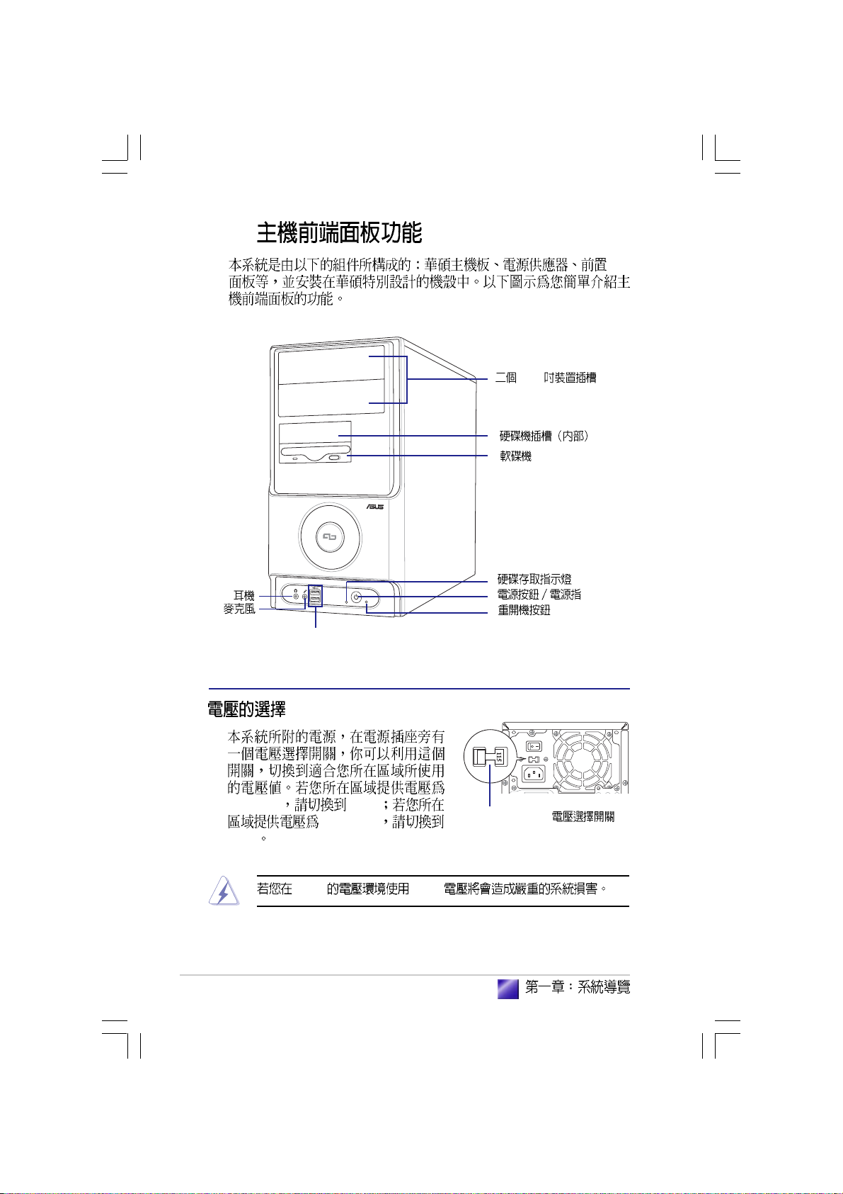
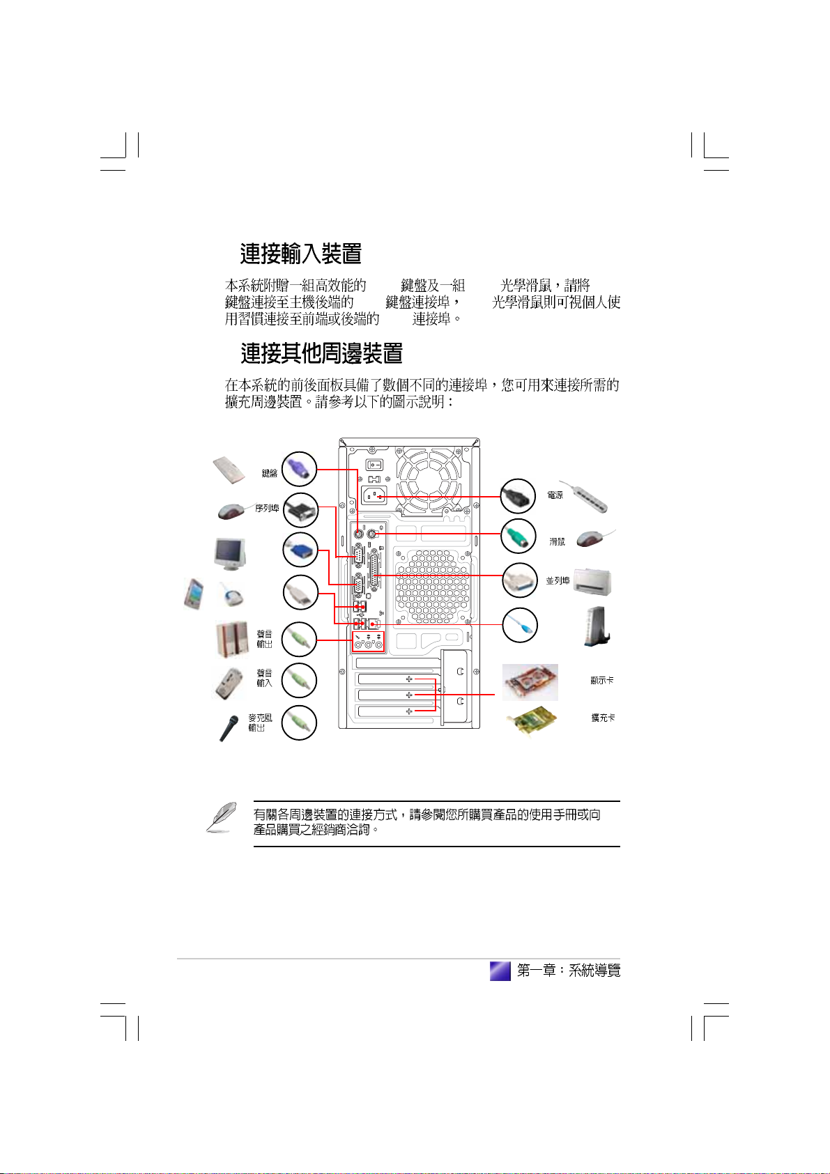
1.1
1.2
1.3
1.4
1.5
1.6
1.2.1
1.2.2
................................................................................
........................................................................................
...............................................................................
...............................................................
........................................................................
........................................................................
................................................................................
........................................................................
11
12
12
13
14
15
16
16
Page 11
1.1
•
•
•
•
•
•
•
•
•
•
1.
2.
11
Page 12
1.2
1.2.1
1. Introduction
AMD® AthlonTM 64 AMD SempronTM AMD
AthlonTM 64 64 x86
32
64
AMD® AthlonTM
AMD SempronTM 32
HyperTransportTM
HyperTransportTM
HyperTransportTM
Cool n Quiet
AMD® Cool n Quiet
Serail ATA
®
12
Serial ATA SATA
Parallel ATA Serial ATA
150MB
SATA RAID
Serial ATA RAID
RAID SiS 965L
RAID Serial ATA RAID 0 RAID 1
Page 13
AGP 8X
AGP 8X AGP 8X AGP 3.0
VGA
2.12GB
USB 2.0
USB 2.0 USB 1.1
12 Mbps USB 2.0 480 Mbps
USB 2.0
USB 2.0 USB 1.1
5.1
1.2.2
CrashFree BIOS2
CrashFree BIOS2 BIOS
BIOS
BIOS BIOS
ROM
C. P. R. CPU
EZ Flash BIOS
BIOS MS-DOS
C.P.R. BIOS
CMOS
BIOS CPU
CPU
EZ Flash BIOS
13
Page 14
1.3
1. Introduction
USB 2.0
I/O
5.25
100-127V 115V
230V
14
200-240V
230V 115V
115V/ 230V
Page 15
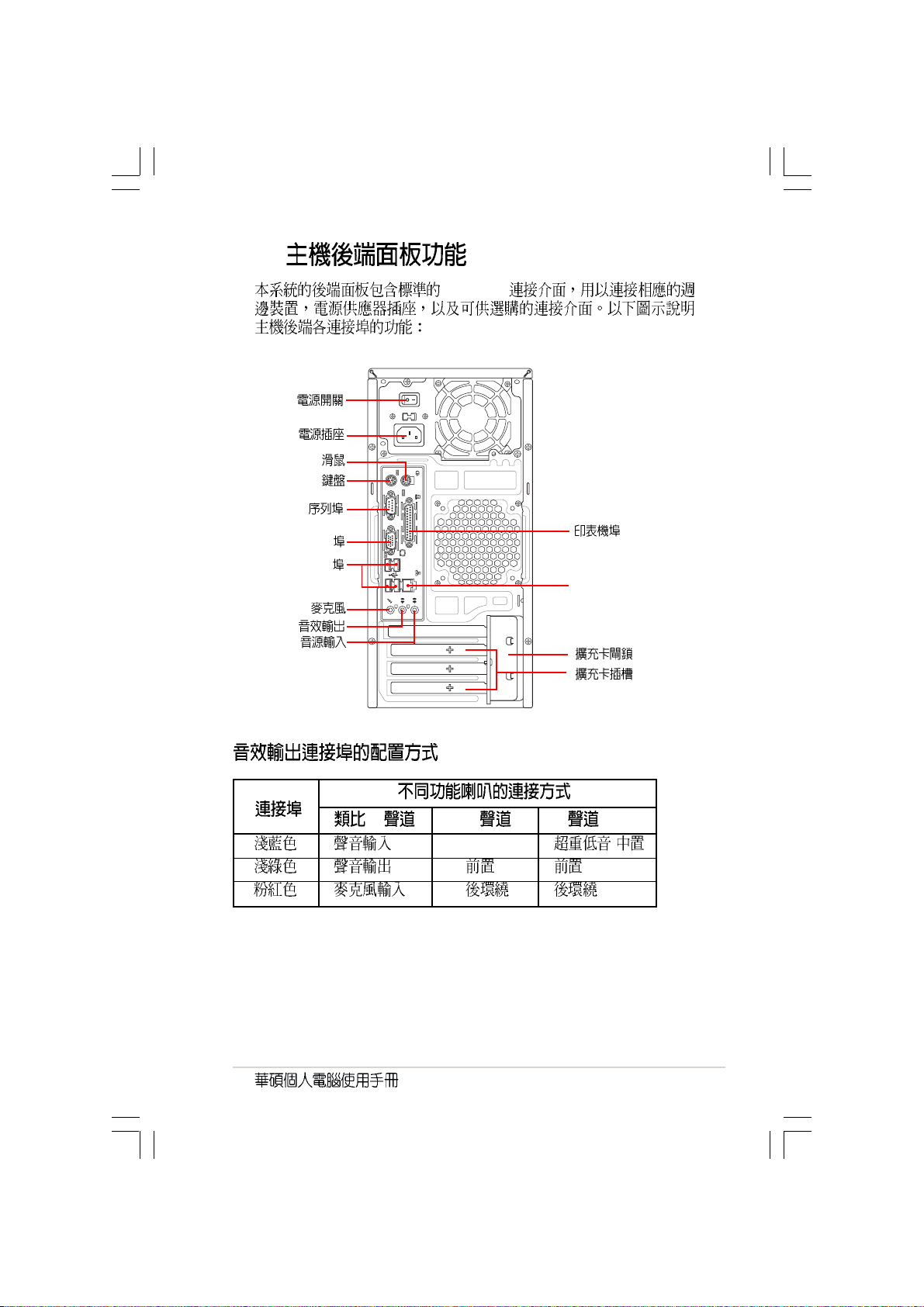
1.4
PC99 I/O
PS/2
PS/2
VGA
USB
RJ-45 LAN
2 4 6
- /
15
Page 16
1.5
1.6
PS/2 USB PS/2
PS/2 USB
USB
PS/2
PS/2
VGA
USB
RJ-45
16
AGP
PCI
Page 17
step-by-step
Page 18
2.1
2.2
2.3 CPU
2.3.1
2.3.2
2.3.3 CPU
2.4
2.4.1
2.4.2
2.4.3
2.4.4
2.5
2.5.1
2.5.2
2.5.3 PCI
2.5.4 PCI Express x1
2.5.5 AGP
2.6
2.6.1
2.6.2
2.6.3
2.7
2.8
....................................................................................
......................................................................................
....................................................................................
........................................................................................
........................................................................................
19
................................................................
....................................................................
..................................................................
....................................................................
..................................................................
..........................................................................
..................................................................
..................................................................
...................................................
.......................................
...........................................................
.........................................
..........................................................
...........................................................................
...........................................................................
...........................................................................
........................................................................
................................................................
20
21
21
22
23
24
24
24
27
27
28
29
29
30
30
30
31
31
32
32
33
33
Page 19
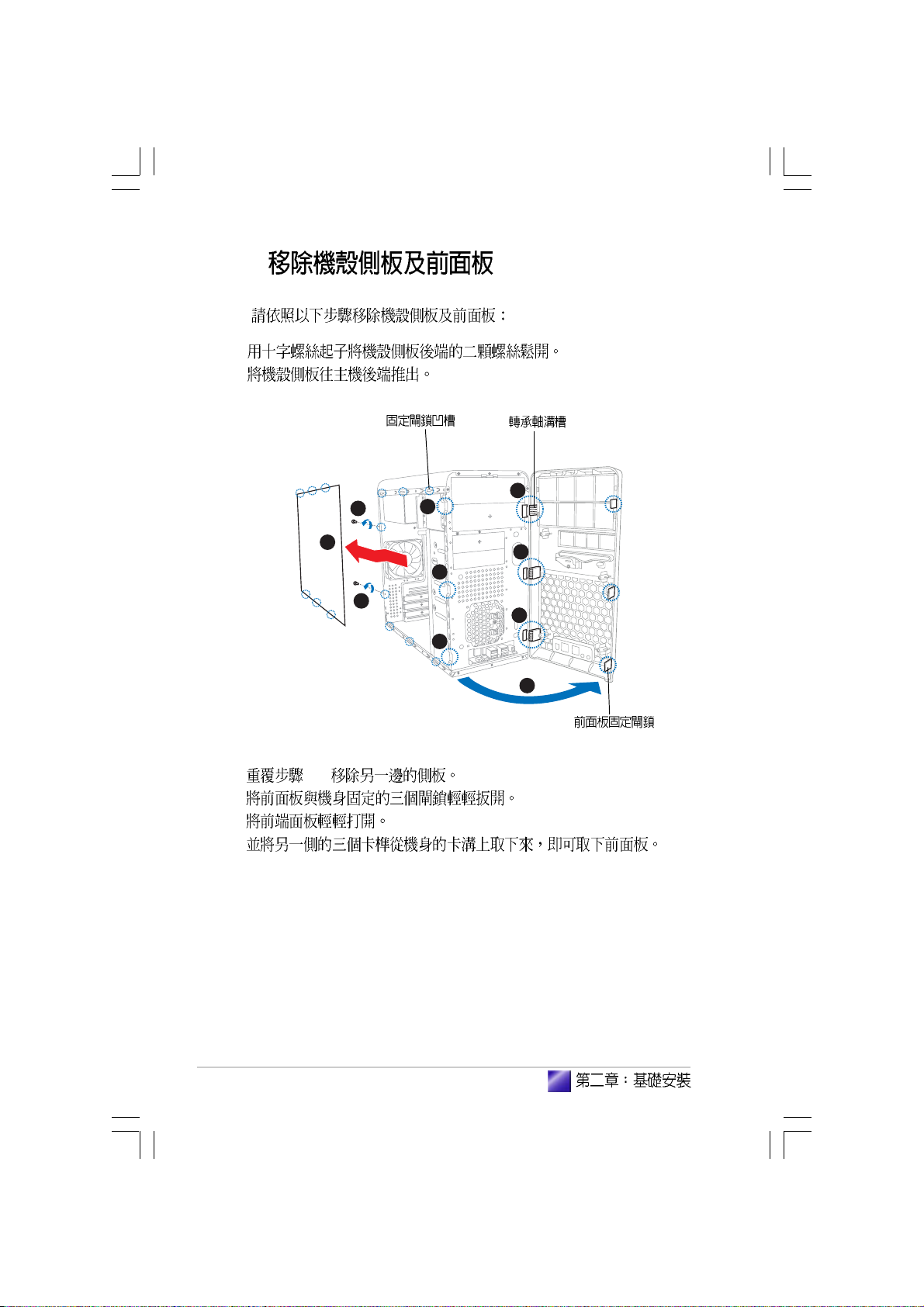
2.1
1.
2.
3.
4.
5.
/
SB_PWR
(1) (2) (3)
®
Onboard LED
ON
Standby
Power
SB_PWR
OFF
Powered
Off
19
Page 20
2.2
1.
2.
6
1
4
3. 1-2
4.
5.
6.
2
4
1
4
6
6
5
20
Page 21
2.3 CPU
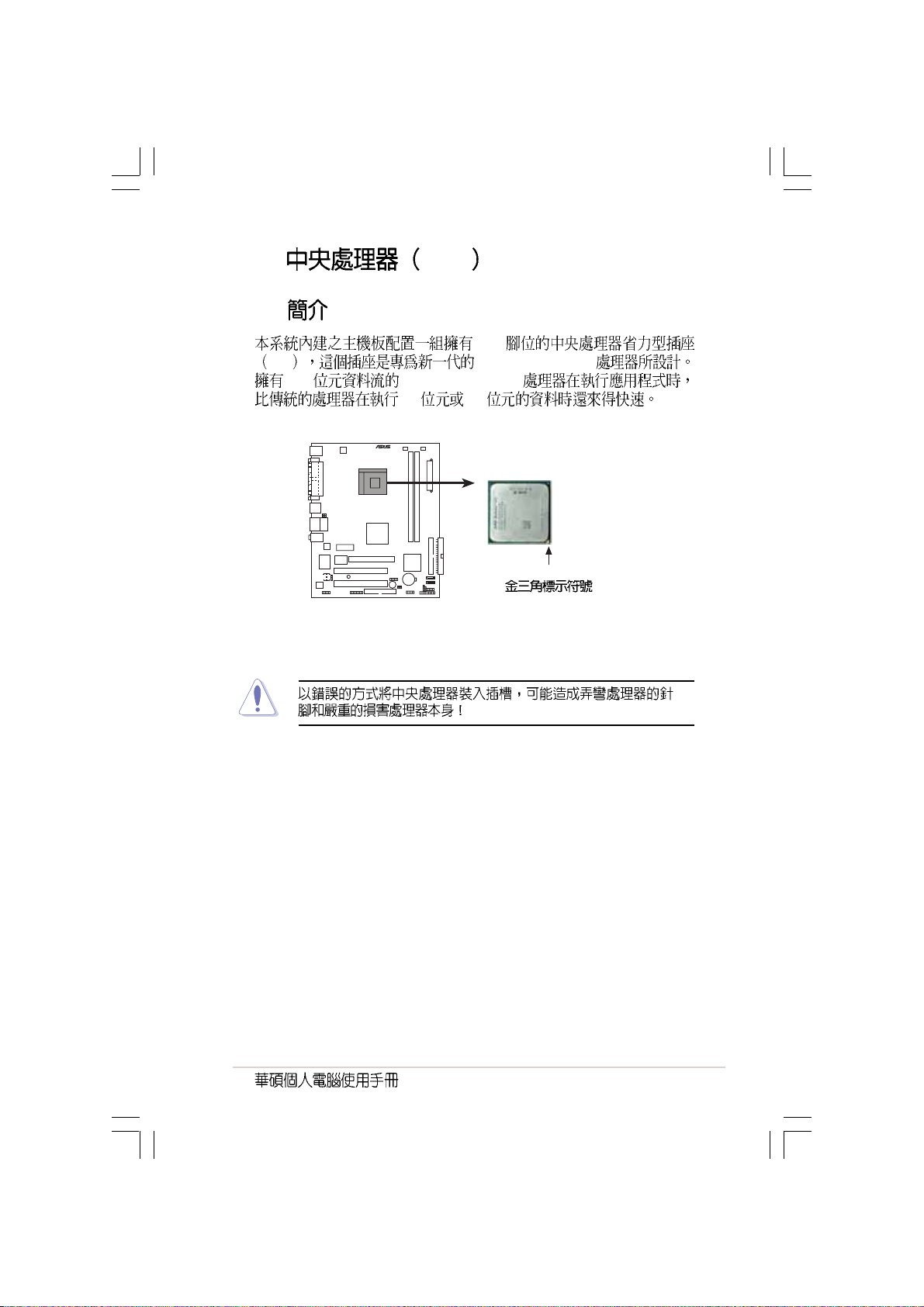
2.3.1
754
ZIF AMD® AthlonTM 64
128 AMD® AthlonTM 64
32 64
®
CPU Socket 754
Gold Arrow
21
Page 22
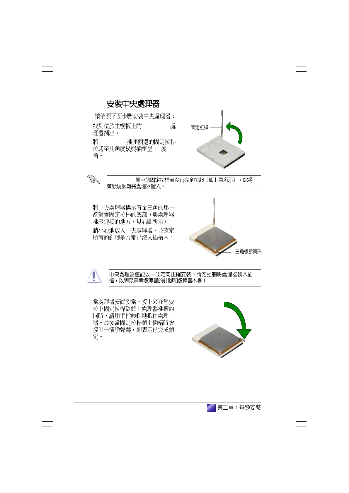
2.3.2
1. Socket-754
2. Socket-754
90
Socket-754
3.
4.
22
5.
Page 23
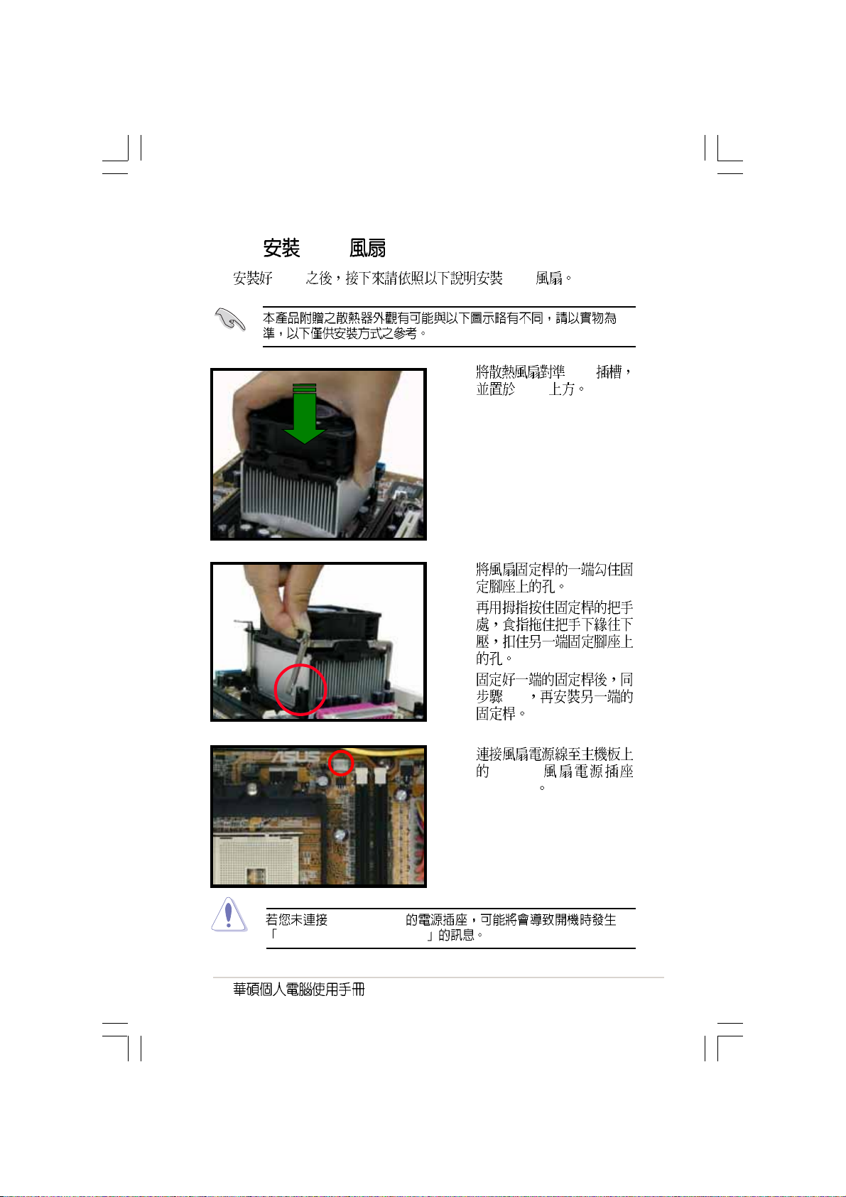
2.3.3 CPU
CPU CPU
1. CPU
CPU
2.
3.
CPU_FAN
Hardware monitoring errors
4.
2-3
5.
CPU
CPU_FAN
23
Page 24
2.4
2.4.1
DDR
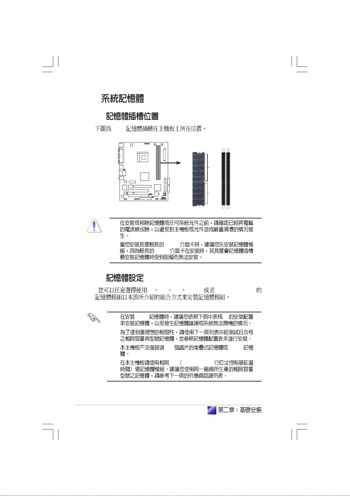
2.4.2
®
184-pin DDR DIMM sockets
1.
2. AGP
AGP
64 128 256 512MB 1GB DDR DIMM
DIMM1
80 Pins 104 Pins
DIMM2
24
1. DDR 1
2.
3. 18 DDR
4. CL CAS-Latency
Page 25
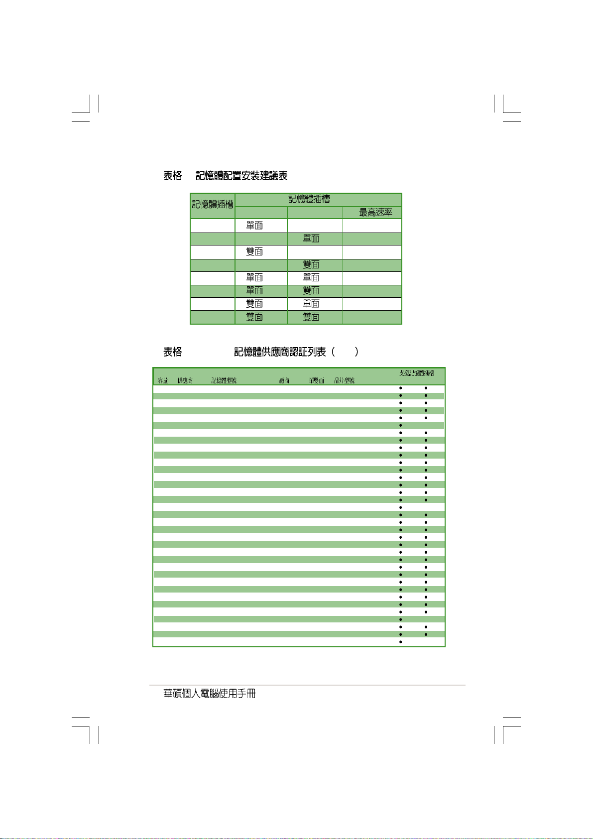
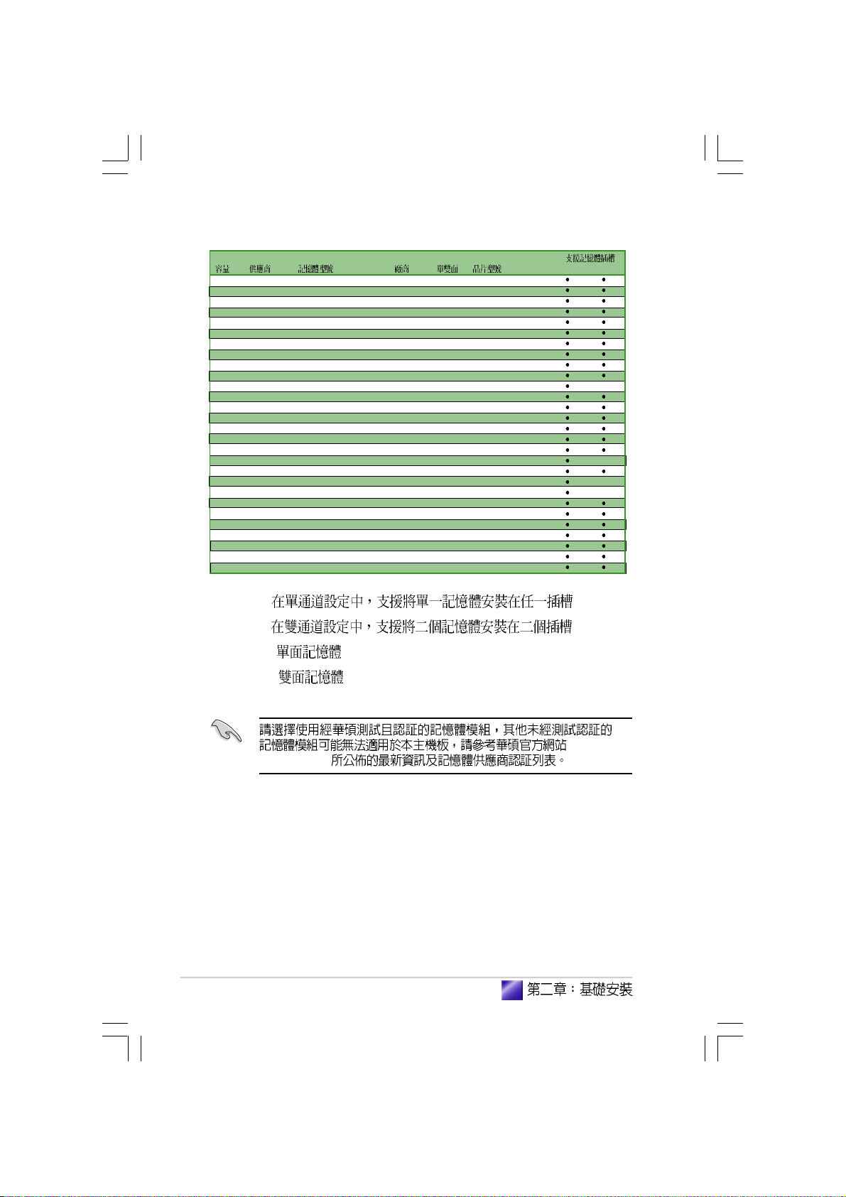
1
DIMM1 DIMM2
1 - DDR 400
11
- DDR 400
12
2
2
2
2 DDR400 QVL
DDR 400
DDR 400
DDR 400
DDR 400
DDR 400
DDR 400
256MB Kingston KVR333X64C25/256 Kingston SS D3208DH1T-6
257MB Kingston KVR333X64C25/256 Hynix SS HY5DU56822BT-J
512MB Kingston KVR333X64C25/512 Hynix DS HY5DU56822BT-J
512MB Kingston KVR400X643A/512 Hynix DS HY5DU56822BT-D43
512MB Kingston KVR400X64C3A/512 Kingston DS D3208DL3T-5
256MB Kingston KVR400X64C3A/256 Hynix SS HY5DU56822BT-D43
256MB Infineon HYS64D64320GU-5-C Infineon SS HYB25D256800CE-5C
512MB Infineon HYS64D32300GU-5-C Infineon DS HYB25D256800CE-5C
256MB Infineon HYS64D64320GU-5-C Infineon SS HYB25D256800CE-5C
512MB Infineon HYS64D64320GU-6-C Infineon DS HYB25D256800CE-6C
256MB HY DDR400-256 Hynix SS HY5DU56822BT-D43
512MB HY DDR400-512 Hynix DS HY5DU56822BT-D43
256MB HY DDR266-256 Hynix SS HY5DU56822AT-H
256MB HY DDR333-256 Hynix SS HY5DU56822BT-J
512MB HY DDR333-512 Hynix DS HY5DU56822BT-J
256MB Corsair VS256MB400 Value select SS VS32M8-5 2B0409
512MB Corsair VS512MB400 Value select DS VS32M8-5 2B0402
256MB Corsair VS256MB333 SAMSUNG SS K4H5608380-TCB3
512MB Corsair VS512MB333 Value select DS VS32M8-6 2B0412
512MB Micron MT16VDDT6464AG-335GB MICRON DS MT46V32M8-G
256MB Micron MT8VDDT3264AG-335GB MICRON SS MT46V32M8-G
256MB Micron MT8VDDT3264AG-40BGB MICRON SS MT46V32M8-G
512MB Micron MT16VDDT6464AG-40BGB MICRON DS MT46V32M8-G
256MB Samsung M368L3223FTN-CCC SAMSUNG SS K4H560838F-TCCC
512MB Samsung M368L6423FTN-CCC SAMSUNG DS K4H560838F-TCCC
256MB Samsung M368L3223FTN-CB3 SAMSUNG SS K4H560838F-TCB3
512MB Samsung M368L6423FTN-CB3 SAMSUNG DS K4H5608838F-TCB3
256MB Winbond U24256ADWBG6H20 Winbond SS W942508CH-5
256MB Winbond U24256AAWBG6H20 Winbond SS W942508CH-6
512MB Winbond DDR333-512 Winbond DS W942508BH-6
512MB Winbond U24512ADWBG6H20 Winbond DS W942508CH-5
256MB Elpida U24256AD1PG6H20 Elpida SS DD2508AKTA-5C
512MB Elpida U24512AD1PG6H20 Elpida DS DD2508AMTA
256MB Transcend DDR400-256 SAMSUNG SS K4H560838F-TCCC
256MB Transcend DDR400-256 Mosel SS V58C2256804SAT5B
AB
25
Page 26
512MB Transcend DDR400-512 Mosel DS V58C2256804SAT5B
512MB Transcend DDR400-512 SAMSUNG DS K4H560838F-TCCC
512MB Transcend DDR333-512 Hynix DS HY5DU56822CT-J
256MB Pmi 3208GATA07-04A7 Pmi SS PM4D328D50406EU
512MB Pmi 3208GATA01-04A4 Pmi DS PM4D328S50403DU
256MB Kingmax MPMB62D-38LT3R Mosel SS V58C2256804SAT6
512MB Kingmax MPMC22D-38HT3R Hynix DS HY5DU56822BT-J
256MB Kingmax MPMB62D-38KT3R KINGMAX SS KDL388P4LA-50
512MB Kingmax MPXC22D-38KT3R KINGMAX DS KDL388P4EA-50
256MB Mosel V826632K24SATG-D3 Mosel SS V58C2256804SAT5
512MB Mosel V826664K24SATG-D3 Mosel DS V58C2256804SAT5
256MB Nanya NT256D64S88B1G-5T Nanya SS NT5DS32M8BT-5T
512MB Nanya NT512D64S8HB1G-5T Nanya DS NT5DS32M8BT-5T
256MB Apacer 77.10628.10A Apacer SS AM3A5608AIT-6B
512MB Apacer 77.90728.U1G Apacer DS AM3A568AJT-6B
512MB Apacer 77.10736.464 SAMSUNG DS K4H560838E-TCCC
512MB Apacer 77.90739.U1G Apacer DS AM3A568AJT-5A
256MB Apacer 77.10636.46G SAMSUNG SS K4H560838E-TCCC
256MB Apacer 77.10636.56G Mosel SS V58C2256804SAT5B
512MB Apacer 77.10736.11G Infineon DS HYB25D256800BT-5B
256MB Smart U24256ADSRG6H20 Smart SS D32M8XS50H3X4AMV
512MB Smart U24512ADSRG6H20 Smart DS D32M8XS50H3X4AMV
512MB Smart U24512ADSKG6H20 Smart DS D32M8XS60HBX4AMV
1G Twinmos M2S5016AJAMC5G0811A-J TWINMOS DS 46V64M8
512MB Twinmos M2S9J18BGAPS9F0811A-T PSC DS A2S56D30ATP
256MB A Data MDOSS1F3G3X10BZL0Z SAMSUNG SS K4H560838E-TCC5
512MB A Data MDOSS1F3H4X10BZL0Z SAMSUNG DS K4H560838E-TCC5
512MB Promos V826662K24SCTG-D0 Promos DS 0415PRV58C2256804SCT5B
AB
A B SS DS -
26
http://
tw.asus.com
Page 27
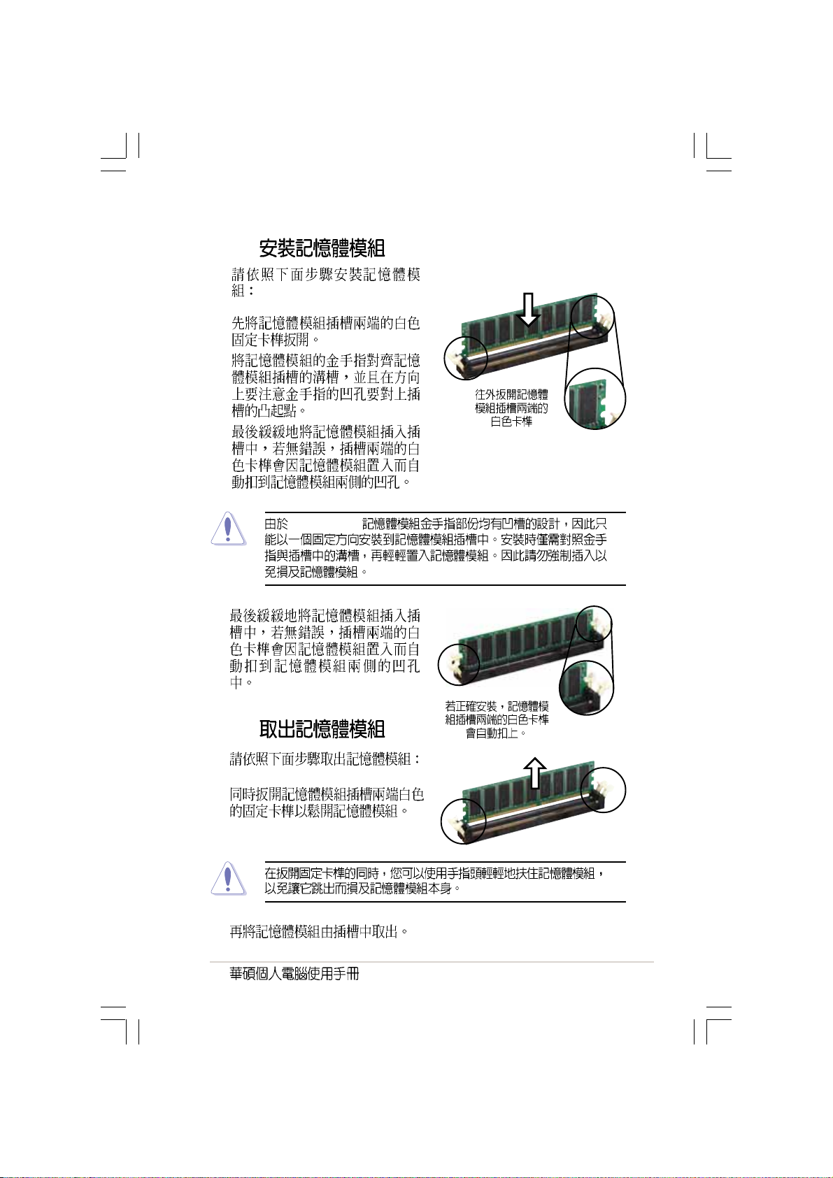
2.4.3
1.
2.
3.
4.
DDR DIMM
2.4.4
1.
2.
27
Page 28
2.5
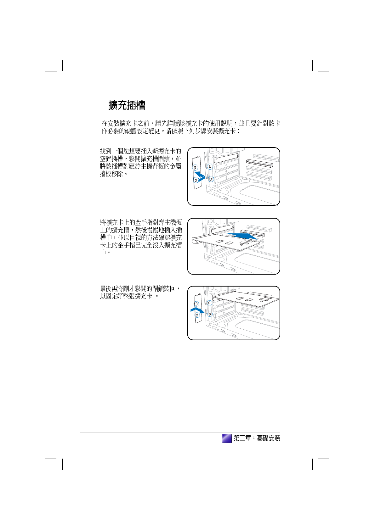
1.
2.
3.
28
Page 29
2.5.1
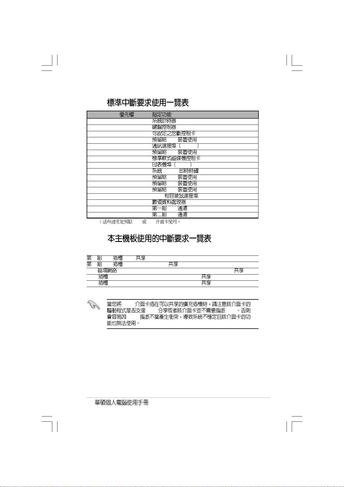
IRQ
01
12
2 N/A
3* 11 PCI
4* 12 COM 1
5* 13 PCI
614
7* 15 LPT 1
83 CMOS/
9* 4 PCI
10* 5 PCI
11* 6 PCI
12* 7 PS/2
13 8
14* 9 IDE
15* 10 IDE
* ISA PCI
2.5.2
INT A INT B INT C INT D
1 PCI ---
2 PCI - -LAN --AGP -- VGA -- -
PCI
IRQ
IRQ IRQ
29
Page 30

2.5.3 PCI
SCSI
USB PCI
PCI
2.5.4 PCI Express x1
x1 PCI
Express
PCI Express x1
SCSI
2.5.5 AGP
AGP
8X AGP 4X AGP
AGP
AGP
30
AGP
Page 31

2.6
2.6.1
3
1.
2.
3.
4. IDE (A)
- Serial ATA (B)
IDE
3
2
IDE
A B
SATA
Serial ATA
SATA Windows XP Windows 2000
Windows XP Windows 2000 F6
31
Page 32

2.6.2
3
3
2
CD-ROM/CD-RW/DVD-ROM/DVD-RW
2
3
1.
2. 5.25
3.
4. IDE
2.6.3
3
IDE
1.
2.
3.
4.
32
Page 33

2.7
2.8
1.
2.
Reset
1
1
6
13
5
3.
4.
5.
6.
7. 4 ~ 6
1
13
1
6
13
14
1
2
33
Page 34

34
Page 35

Page 36

3.1
3.2
3.3
3.3.1
3.3.2 Drivers Menu
3.3.3 Utilities Menu
3.3.4
3.4
3.4.1
3.4.2
3.4.3
................................................................................
........................................................................................
..................................................................
............................................................................
...........................................................
...........................................................
37
37
....................................................
..........................................
...............................
..............................
...............................................
38
38
38
39
40
41
41
42
45
Page 37

3.1
3.2
Windows 2000/XP
37
Page 38

3.3
3.3.1
http://tw.asus.com
3.3.2 Drivers Menu
38
Page 39

AGP SiS760
AGP SiS760
AD1888 SoundMAX
AD1888 AC 97
SiS1RAID Controller
SiS RAID Controller
SiS1RAID Controller
SiS RAID Controller
SiS191/SiS190
SiS191/SiS190 LAN 10/100 LAN
100Mbps
Cool n Quiet
AMD Cool n Quiet
USB 2.0
USB 2.0 USB 1.1 USB 2.0
Windows XP Windows
XP Service Pack 1 USB 2.0
3.3.3 Utilities Menu
39
Page 40

ASUS AMD Cool n Quiet
AMD Cool n Quiet
ASUS PC Probe
ASUS Live Update
BIOS
MyLogoTM
Microsoft DirectX 9.0
DirectX 9.0
Adobe Acrobat Reader
Adobe Acrobat Reader PDF Portable
Document Format
40
3.3.4
Page 41

3.4
3.4.1
CPU
Show up in next execution
\
- ASUS Utility\Probe Vx.xx Vx.xx
41
Page 42

3.4.2
CPU
CPU
CPU
CPU
42
CPU
Page 43

CPU
CPU
CPU CPU
CPU
CPU
FAT
43
Page 44

44
DMI
CPU
CPU
Page 45

3.4.3
CPU !!!
45
Page 46

46
Page 47

Jumper
BIOS
<Del> BIOS
( )
Page 48

4.1
4.2
4.3
4.4
................................................................................................
................................................................................
....................................................................................
................................................................
4.4.1
4.4.2
..................................................................
..............................................................
49
49
50
52
52
53
Page 49

4.1
4.2
PS/2KBMS
T: Mouse
B: Keyboard
COM1
VGA
PARALLEL PORT
ATX12V
19.9cm (7.8in)
Socket 754
®
CHA_FAN
CPU_FAN
ATXPWR
USB12
Bottom:
USB34
Top:Line In
Center:Line Out
Below:Mic In
AUX
AD1888
USBPW34
USBPW12
Top:
RJ-45
RTL8201CL
I/O
Super
CD
FP_AUDIO
PCIEX1_1
4M
BIOS
SPDIF_OUT
SIS
760GX
Accelerated Graphics Port (AGP)
PCI1
SB_PWR
PCI2
GAME
FLOPPY
USB78
BUZZER
DDR DIMM2 (64 bit, 184-pin module)
DDR DIMM1 (64 bit, 184-pin module)
SIS
965L
CLRTC
CHASSIS
PANEL
SEC_IDE
SATA2
SATA1
CR2032 3V
Lithium Cell
CMOS Power
USBPW78
USBPW56
USB56
24.4cm (9.6in)
PRI_IDE
49
Page 50

4.3
1. CMOS CLRTC
CMOS
CMOS
1
2 CLRTC [1-2] [2-3]
CMOS [1-2]
3
4 Del BIOS
BIOS
CMOS
®
50
CLRTC
3
2
Clear RTC RAM
2
1
Normal Clear CMOS
(Default)
CMOS C.P.R. CPU
BIOS
Page 51

2. USB 3-pin USBPWR12, USBPWR34,
USBPWR56, USBPWR78
+5V USB S1
+5VSB S3 S4
USBPWR12 USBPWR34
USB USBPWR56 USBPWR78
USB
®
+5V
(Default)
USB device wake-up
+5V
(Default)
1. USB +5VSB
500mA/+5VSB
2.
+5VSB
USBPW34
USBPW12
21
USBPW78
USBPW56
21
2
+5VSB
2
+5VSB
3
3
51
Page 52

4.4
4.4.1
1
11 10
2
9 8
3
4
5
6
7
1. PS/2 PS/2
2.
3. RJ-45 LAN
Local Area Network
4.
5.
6.
52
Page 53

7. USB 2.0 3 4 USB
USB 2.0
8. USB 2.0 1 2 USB
USB 2.0
9. VGA VGA VGA
10. 9-pin COM1
11. PS/2 PS/2
4.4.2
1. IDE 40-1 pin PRI_IDE, SEC_IDE
IDE
IDE CD-ROM ZIP MO
Primary
Secondary Slave
UltraATA133 IDE
Master UltraATA133 IDE
1. IDE
Master
Slave
2. IDE
UltraDMA
3. UltraATA
®
IDE connectors
PIN 1
SEC_IDE
NOTE: Orient the red markings
(usually zigzag) on the IDE
ribbon cable to PIN 1.
PRI_IDE
53
Page 54

2. 20-pin ATXPWR, 4-pin ATX12V
ATX 12V
20 ATXPWR
+12V
ATX 12V +12V 8
+5VSB 1
230
300
®
GND
+12V DC
GND
+12V DC
ATX power connectors
3. 34-1 pin FLOPPY
®
FLOPPY
NOTE: Orient the red markings on
the floppy ribbon cable to PIN 1.
+5V Standby
Power OK
Pin 1
+3 Volts
+12 Volts
+12 Volts
Ground
+5 Volts
Ground
+5 Volts
Ground
+3 Volts
+3 Volts
ATXPWRATX12V
Ground
+5 Volts
+5 Volts
+5 Volts
-5 Volts
Ground
Ground
Ground
PSON#
Ground
-12 Volts
+3 Volts
54
Floppy disk drive connector
PIN 1
Page 55

4. 4-pin CD, AUX
®
MPEG
AUX (White)
Left Audio Channel
Ground
Right Audio Channel
Right Audio Channel
Ground
Left Audio Channel
Internal audio connectors
5. / 3-pin CPU_FAN,
CHA_FAN
350 740 8.88 1 2.22
26.64 /+12
+12V
GND
CD (Black)
Fan connectors
®
CPU_FANCHA_FAN
GND
+12V
Rotation
GND
+12V
Rotation
55
Page 56

6. USB 10-1 pin USB56, USB78
USB
USB USB
USB USB 2.0
USB 2.0 USB
®
USB+5V
USB_P8-
USB78
1
USB 2.0 connectors
USB+5V
USB_P7-
1.
2. USB 2.0 USB 2.0
USB_P8+
GND
NC
GND
USB_P7+
USB56
USB+5V
1
USB+5V
USB_P6-
USB_P6+
GND
GND
USB_P5-
USB_P5+
NC
56
Page 57

7. 10-1 FP_AUDIO
Intel
/
LINE OUT_R/BLINE_OUT_R
LINE OUT_L/BLINE_OUT_L
®
FP_AUDIO
Front panel audio connector
8. 4-1 pin CHASSIS
MICPWR
Line out_R
NC
Line out_L
+5VA
BLINE_OUT_L
BLINE_OUT_R
MIC2
AGND
Signal GND
Chassis Signal GND
Chassis intrusion connector
CHASIS Chassis
®
CHASSIS
GND
Chassis Signal
+5VSB_MB
(Default)
57
Page 58

9. /MIDI 16-1 pin GAME1
/MIDI USB 2.0/
/MIDI
/MIDI
MIDI
®
+5V
J2B1
J2CX
MIDI_OUT
J2CY
J2B2
MIDI_IN
GAME1
GAME1
Game connector
+5V
J1B1
J1CX
GND
GND
J1B2
J1CY
+5V
10. Serial ATA RAID 7-pin SATA1, SATA2
Serial ATA Serial ATA
150MB 133MB
Parallel ATA UltraATA 133
58
®
SATA connectors
GND
GND
RSATA_RXP2
RSATA_RXN2
RSATA_TXN2
SATA2
RSATA_TXN1
GND
RSATA_RXP1
GND
RSATA_RXN1
SATA1
RSATA_TXP2
RSATA_TXP1
GND
GND
Page 59

11. 4-1 pin SPDIF_OUT
S/PDIF S/
PDIF
®
SPDIF_OUT
GND
SPDIFOUT
+5V
Digital audio connector
59
Page 60

12. 10-1 pin PANEL
®
PLED-
SPEAKER
+5V
PLED
PLED+
PANEL
+5V
PWR
Ground
IDELED
IDE_LED
System panel connector
•
•
4-pin SPEAKER
•
* Requires an ATX power supply.
3-1 pin PLED
2-pin RESET
PWRSW
Reset
ATX / 2-pin PWRSW
•
BIOS
Ground
Speaker
Ground
Reset
Ground
RESET
60
IDE 2-pin IDE_LED
•
IDE_LED IDE
IDE
Page 61

BIOS
( )
BIOS
BIOS
BIOS
<Del> BIOS
Page 62

5.1 BIOS
5.1.1
5.1.2 AFUDOS BIOS
5.1.3 AFUDOS BIOS
5.1.4 EZ Flash BIOS
5.1.5 CrashFree BIOS 2 BIOS
5.1.6
5.2 BIOS
5.2.1 BIOS
5.3 Main Menu
5.3.1 System Time [XX:XX:XX]
5.3.2 System Date [XX/XX/XXXX]
5.3.3 Legacy Diskette A [1.44M, 3.5 in.]
5.3.4 IDE Primary and Secondary IDE Master/Slave 76
5.3.5 Onboard PCI S-ATA Controller [Enabled]
5.3.6 System Information
5.4 Advanced menu
5.4.1 CPU Configuration
5.4.2 Chipset
5.4.3 OnBoard Devices Configuration
5.4.4 PCI PCI PnP
5.5 Power menu
5.5.1 Suspend Mode [S1&S3(STR)]
5.5.2 Repost Video on S3 Resume [No]
5.5.3 ACPI 2.0 Support [No]
5.5.4 ACPI APIC Support [Enabled]
5.5.5 APM Configuration
5.5.6 Hardware Monitor
5.6 Boot menu
5.6.1 Boot Device Priority
5.6.2 Boot Settings Configuration
5.6.3 Security
5.7 BIOS Exit menu
.......................................................................
..............................................................................
.........................................................
...................................................................
..........................................
..........................................
...................................
....................
.............................................................
..................................................................
..................................................
.............................................
......................................
..........................
.......................................
......................................................
...................................
..........................................................
..........................................
............................................................
..............................................
........................................
.........................................................
.............................................
.......................
.................................
...............................................................
.............................
..................
.....................................................
.....................................................
...........
63
63
64
65
66
67
69
72
73
75
75
75
75
77
77
78
78
80
82
85
86
86
86
86
86
87
88
90
90
91
92
95
62
BIOS
Page 63

5.1 BIOS
BIOS
1. AFUDOS DOS BIOS
2. ASUS EZ Flash Power-On Self
Test POST BIOS
3. ASUS CrashFree BIOS 2 BIOS
BIOS
4. ASUS Update Windows BIOS
1. BIOS
BIOS AFUDOS
BIOS
2. BIOS
BIOS
3. http://tw.asus.com
BIOS
5.1.1
1.
DOS
1.44MB DOS
format A:/S Enter
Windows XP
a. 1.44MB
b. Windows
c. 3 1/2
d. File Format Format 3 1/
2 Floppy Disk
c. Create a MS-DOS startup disk
63
Page 64

Windows 2000
a. 1.44MB
b. Windows 2000
c. Run
d. D:\bootdisk\makeboot a:
D
e. Enter
2. BIOS
5.1.2 AFUDOS BIOS
DOS AFUDOS.EXE BIOS
1. tw.asus.com BIOS
BIOS
BIOS
2. AFUDOS.EXE
BIOS
3.
4. DOS
afudos /i[filename]
filename
BIOS
5. Enter
BIOS
A:\>afudos /iK8S-MV.rom
AMI Firmware Update Utility - Version 1.10
Copyright (C) 2002 American Megatrends, Inc. All rights reserved.
Reading file ..... done
Erasing flash .... done
Writing flash .... 0x0008CC00 (9%)
BIOS
64
BIOS
Page 65

DOS
A:\>afudos /iK8S-MV.rom
AMI Firmware Update Utility - Version 1.10
Copyright (C) 2002 American Megatrends, Inc. All rights reserved.
Reading file ..... done
Erasing flash .... done
Writing flash .... 0x0008CC00 (9%)
Verifying flash .. done
A:\>
6.
5.1.3 AFUDOS BIOS
AFUDOS.EXE BIOS
BIOS
1. DOS
afudos /o[filename]
filename
2. Enter
BIOS
A:\>afudos /oMYBIOS03.rom
AMI Firmware Update Utility - Version 1.10
Copyright (C) 2002 American Megatrends, Inc. All rights reserved.
Reading flash ..... 0x0008CC00 (9%)
65
Page 66

3. BIOS
600KB
A:\>afudos /oMYBIOS03.rom
AMI Firmware Update Utility - Version 1.10
Copyright (C) 2002 American Megatrends, Inc. All rights reserved.
Reading flash ..... done
A:\>
BIOS DOS
5.1.4 EZ Flash BIOS
EZ Flash BIOS
DOS EZ Flash BIOS
Power-On Self
Test POST Alt + F2 EZ Flash
EZ Flash BIOS
1. tw.asus.com BIOS
2.
3. POST Alt + F2
EZ Flash
User recovery requested. Starting BIOS recovery...
Checking for floppy...
•
Floppy not found
•
K8S-MV.ROM not found
BIOS K8S-MV.ROM
66
BIOS
BIOS
Page 67

4. BIOS
EZ Flash BIOS
BIOS
User recovery requested. Starting BIOS recovery...
Checking for floppy...
Floppy found!
Reading file “K8S-MV.rom”. Completed.
Start flashing...
Flashed successfully. Rebooting.
5.1.5 CrashFree BIOS 2 BIOS
CrashFree BIOS 2 BIOS
BIOS BIOS
1. BIOS
BIOS
2. BIOS
BIOS 5.1.1
BIOS
1.
2. BIOS
Bad BIOS checksum. Starting BIOS recovery...
Checking for floppy...
3. BIOS
BIOS K8S-MV.ROM
BIOS
67
Page 68

Bad BIOS checksum. Starting BIOS recovery...
Checking for floppy...
Floppy found!
Reading file “K8S-MV.rom”. Completed.
Start flashing...
BIOS
4.
BIOS
1.
2. BIOS
Bad BIOS checksum. Starting BIOS recovery...
Checking for floppy...
3.
BIOS
Bad BIOS checksum. Starting BIOS recovery...
Checking for floppy...
Floppy not found!
Checking for CD-ROM...
CD-ROM found.
Reading file “K8S-MV.rom”. Completed.
Start flashing...
BIOS
4. BIOS
BIOS BIOS
http://tw.asus.com BIOS
68
BIOS
Page 69

5.1.6
Windows
BIOS
1. BIOS
2. BIOS
3. BIOS BIOS
4. BIOS
5. BIOS
ISP
1.
2. VX.XX.
XX
3.
BIOS
69
Page 70

BIOS
BIOS
1. ASUS ASUSUpdate ASUSUpdate
2. Update
BIOS from the Internet
Next
3. FTP
Auto Select
Next
70
BIOS
Page 71

4. BIOS
Next
5.
BIOS
BIOS
BIOS BIOS
BIOS BIOS
1. ASUS
ASUSUpdate ASUSUpdate
2. Update BIOS
from a file Next
3. BIOS
4.
BIOS
71
Page 72

5.2 BIOS
BIOS Basic Input and Output System
BIOS
BIOS
RUN SETUP BIOS
BIOS
Flash ROM BIOS Flash
ROM
BIOS BIOS
BIOS
CMOS RAM
POST Power-On Self Test
Del Del
BIOS
BIOS
72
Ctrl + Alt + Del
BIOS
BIOS
BIOS
5.7 BIOS Load Setup Defaults
BIOS
http://tw.asus.com BIOS
BIOS
BIOS
Page 73

5.2.1 BIOS
System Time [11:51:19]
System Date [Thu 08/05/2003]
Legacy Diskette A [1.44M, 3.5 in]
Primary IDE Master : [ST320413A]
Primary IDE Slave : [ASUS CD-S340]
Secondary IDE Master : [Not Detected]
Secondary IDE Slave : [Not Detected]
Onboard PCI S-ATA Controller [Disabled]
System Information
BIOS
Main
Advanced
Power
Boot
Exit BIOS
Use [ENTER], [TAB]
or [SHIFT-TAB] to
select a field.
Use [+] or [-] to
configure system time.
73
Page 74

Advanced Power Boot Exit
Enter
System Time [11:51:19]
System Date [Thu 08/05/2003]
Legacy Diskette A [1.44M, 3.5 in]
Language [English]
Primary IDE Master :[ST320413A]
Primary IDE Slave :[ASUS CD-S340]
Secondary IDE Master :[Not Detected]
Secondary IDE Slave :[Not Detected]
System Information
[Enter]
Primary Graphics Adapter [AGP]
Search for MDA Resources [Yes]
AGP Mode [AGP 8X]
AGP Fast Write [Enabled]
Graphics Aperture Size [64MB]
Use [ENTER], [TAB]
or [SHIFT-TAB] to
select a field.
Use [+] or [-] to
configure system time.
Select Screen
Select Item
+- Change Field
Tab Select Field
F1 General Help
F10 Save and Exit
ESC Exit
Select Screen
Select Item
+- Change Option
F1 General Help
F10 Save and Exit
ESC Exit
74
PageUp/PageDown
BIOS
Page 75

5.3 Main Menu
BIOS
5.2.1 BIOS
System Time [11:51:19]
System Date [Thu 08/05/2003]
Legacy Diskette A [1.44M, 3.5 in]
Primary IDE Master : [ST320413A]
Primary IDE Slave : [ASUS CD-S340]
Secondary IDE Master : [Not Detected]
Secondary IDE Slave : [Not Detected]
Onboard PCI S-ATA Controller [Native]
System Information
Use [ENTER], [TAB]
or [SHIFT-TAB] to
select a field.
Use [+] or [-] to
configure system time.
5.3.1 System Time [XX:XX:XX]
5.3.2 System Date [XX/XX/XXXX]
5.3.3 Legacy Diskette A [1.44M, 3.5 in.]
[Disabled] [360K
5.25 in.] [1.2M 5.25 in.] [720K 3.5 in.] [1.44M 3.5 in,] [2.88M 3.5
in.]
75
Page 76

5.3.4 IDE Primary and Secondary IDE
Master/Slave
BIOS IDE
IDE
Enter
Primary IDE Master
Device : Hard Disk
Vendor : ST320413A
Size : 20.0GB
LBA Mode : Supported
Block Mode : 16 Sectors
PIO Mode : Supported
Async DMA : MultiWord DMA-2
Ultra DMA : Ultra DMA-5
SMART Monitoring: Supported
Type [Auto]
LBA/Large Mode [Auto]
Block(Multi-sector Transfer) [Auto]
PIO Mode [Auto]
DMA Mode [Auto]
Smart Monitoring [Auto]
32Bit Data Transfer [Disabled]
Select the type
of device connected
to the system
Device Vendor Size LBA Mode Block
Mode PIO Mode Async DMA Ultra DMA SMART monitoring
BIOS
Not Detected
Type [Auto]
IDE Auto
IDE CDROM IDE
ARMD ATAPI
IDE ZIP LS-120 MO
[Not Installed] [Auto] [CDROM] [ARMD]
LBA/Large Mode [Auto]
LBA [Auto]
LBA LBA
[Disabled] [Auto]
Block (Multi-sector Transfer) [Auto]
[Auto]
[Disabled]
[Disabled] [Auto]
76
BIOS
Page 77

PIO Mode [Auto]
PIO [Auto] [0] [1] [2] [3] [4]
DMA Mode [Auto]
DMA [Auto] [SWDMA0] [SWDMA1] [SWDMA2]
[MWDMA0] [MWDMA1] [MWDMA2] [UDMA0] [UDMA1] [UDMA2]
[UDMA3] [UDMA4] [UDMA5]
SMART Monitoring [Auto]
Smart Monitoring, Analysis,
and Reporting Technology [Auto] [Disabled] [Enabled]
32Bit Data Transfer [Disabled]
32 [Disabled] [Enabled]
5.3.5 Onboard PCI S-ATA Controller [RAID by Rom]
PCI Serial ATA
[Disabled] [Native] [RAID by Rom]
5.3.6 System Information
BIOS
AMIBIOS
Version : 0202
Build Date : 07/26/04
Processor
Type : AMD Athlon(tm) 64 Processor 3200+
Speed : 2200 MHz
Count : 1
System Memory
Size : 512MB
AMIBIOS
BIOS
Processor
System Memory
77
Page 78

5.4 Advanced menu
CPU Configuration
Chipset
Onboard Devices Configuration
PCI PnP
5.4.1 CPU Configuration
CPU Configuration
Cool N’Quiet [Enabled]
Memory Configuration
Cool N Quiet [Enabled]
AMD Cool N Quiet
[Enabled] [Disabled]
AMD Cool N Quiet
[Enabled]
78
This option should
remain disabled for
the normal operation.
The driver developer
may enable it for
testing purpose.
BIOS
Page 79

Memory Configuration
CPU Configuration
Burst Length [4 Beats]
Memclock Mode [Auto]
Memory CLK : 166 MHz
CAS Latency : 2.5
TRCD : 3 CLK
TRP : 3 CLK
TRAS : 7 CLK
Burst Length [4 Beats]
[8 Beats] [4 Beats] [2 Beats]
Memclock Mode [ Auto]
[Auto] [Limit] [Auto] [Limit]
Memclock Value [100MHz]
Memclock Mode [Limit]
[100MHz] [133MHz] [166MHz] [200
MHz]
79
Page 80

5.4.2 Chipset
Enter
Chipset Settings
AGP Configuration
HyperTransport Configuration
MPS Configuration
AGP AGP Configuration
Aperture Size [64MB]
Graphics Adapter Priority [AGP/Int-VGA]
AGP Fast Write [Disabled]
Select AGP 3.0 Data Ratio [8X]
Share Memory [ 32MB]
Aperture Size [64MB]
AGP
[32MB] [64MB] [128MB]
Graphics Adapter Priority [AGP/Int-VGA]
PCI AGP
[Internal VGA] [AGP/Int-VGA] [AGP/PCI] [PCI/AGP]
[PCI/Int-VGA]
AGP Fast Write [Disabled]
AGP [Disabled]
[Enabled]
Select AGP 3.0 Data Ratio [8X]
AGP 3.0 [8X] [4X]
Share Memory [ 32MB]
[128MB]
VGA
[ 32MB] [ 64MB]
80
BIOS
Page 81

HyperTransport Configuration
Enter
HyperTransport Configuration
HT Width [ 8x16 BIT]
HT Speed [800 MHz]
HT Width [8x16 BIT]
HyperTransport [8x8
BIT] [16x16 BIT] [16x8 BIT] [8x16 BIT]
HT Speed [800 MHz]
HyperTransport K8 CPU AGP
[200 MHz] [400 Mhz] [600 Mhz] [800 Mhz]
MPS MPS Configuration
MPS Configuration
MPS Revision [1.4]
MPS Revision [1.4]
MPS [1.1] [1.4]
81
Page 82

5.4.3 OnBoard Devices
Configuration
Onboard AC97 Audio DEVICE [Enabled]
Onboard SiS190 LAN DEVICE [Enabled]
SiS190 LAN Boot ROM [Disabled]
USB Configuration
Serial Port1 Address [3F8/IRQ4]
Serial Port2 Address [2F8/IRQ3]
Serial Port2 Mode [Normal]
Parallel Port Address [378]
Parallel Port Mode [ECP]
ECP Mode DMA Channel [DMA3]
Parallel Port IRQ [IRQ7]
Onboard Game/MIDI Port [Disabled]
OnBoard AC 97 Audio DEVICE [Enabled]
[Enabled] BIOS
BIOS
BIOS
[Disabled] [Disabled] [Enabled]
OnBoard SiS190 LAN DEVICE [Enabled]
SIS190 LAN
[Disabled] [Enabled]
SiS190 LAN Boot ROM [Disabled]
[Disabled] [Enabled]
82
SiS190
BIOS
Page 83

USB USB Configurations
USB
Enter
USB Configuration
USB Devices Enabled: None
Onboard SiS USB1.1 DEVICE [Enabled]
Onboard SiS USB2.0 DEVICE [Enabled]
Legacy USB Support [Auto]
USB 2.0 Controller Mode [HiSpeed]
Stop EHCI HC in OHCI handover [Enabled]
USB Devices Enabled
USB None
OnBoard SiS USB1.1 DEVICE [Enabled]
SiS USB 1.1 [Disabled]
[Enabled]
OnBoard SiS USB2.0 DEVICE [Enabled]
SiS USB 2.0 [Disabled]
[Enabled]
Legacy USB Support [Auto]
USB [Auto]
USB
USB Legacy
[Disabled] USB USB
[Disabled] [Enabled] [Auto]
USB 2.0 Controller Mode [HiSpeed]
USB 2.0
HiSpeed 480 Mbps FullSpeed 12 Mbps
[HiSpeed] [FullSpeed]
Stop EHCI HC in OHCI handover [Enabled]
OHCI handover EHCI HC
EHCI
[Enabled] [Disabled] [Enabled]
83
Page 84

Serial Port1 Address [3F8/IRQ4]
COM1 [Disabled] [3F8/
IRQ4] [3E8/IRQ4] [2E8/IRQ3]
Serial Port2 Address [3F8/IRQ4]
COM2 [Disabled][2F8/
IRQ3] [3E8/IRQ4] [2E8/IRQ3]
Serial Port2 Mode [Normal]
Serial Port [Normal] [IrDA] [ASK IR]
Parallel Port Address [378]
[278] [3BC]
Parallel Port Mode [Normal]
Parallel Port [Normal] [Bi-Directional]
[EPP] [ECP]
EPP Version [1.9]
Parallel Port Mode [EPP]
Parallel Port EPP [1.9] [1.7]
ECP Mode DMA Channel [DMA3]
Parallel Port Mode [ECP]
Parallel Port ECP DMA [DMA0] [DMA1]
[DMA3]
[Disabled] [378]
Parallel Port IRQ [IRQ7]
[IRQ5] [IRQ7]
Onboard Game/MIDI Port [Disabled]
GAME/MIDI
[Disabled] [200/300] [200/330] [208/300] [208/330]
84
BIOS
Page 85

5.4.4 PCI PCI PnP
PCI/PnP PCI/PnP
IRQ DMA
Advanced PCI/PnP Settings
WARNING: Setting wrong values in below sections
may cause system to malfunction.
Plug And Play O/S [No]
PCI Latency Timer [64]
Allocate IRQ to PCI VGA [Yes]
Palette Snooping [Disabled]
PCI IDE BusMaster [Enabled]
OffBoard PCI/ISA IDE Card [Auto]
IRQ3 [Available]
IRQ4 [Available]
IRQ5 [Available]
IRQ7 [Available]
IRQ9 [Available]
IRQ10 [Available]
IRQ11 [Available]
IRQ14 [Available]
IRQ15 [Available]
Plug and Play O/S [No]
[No] BIOS
[Yes] [No] [Yes]
PCI Latency Timer [64]
PCI [32] [64]
[96] [128] [160] [192] [224] [248]
Allocate IRQ to PCI VGA [Yes]
PCI IRQ
[Yes] [No]
Palette Snooping [Disabled]
MPEG
[Enabled]
VGA [Disabled]
[Disabled] [Enabled]
PCI IDE BusMaster [Enabled]
BIOS PCI
IDE [Disabled] [Enabled]
NO: Lets the BIOS
configure all the
devices in the system.
YES: Lets the
operating system
configure Plug and
Play (PnP) devices not
required for boot if
your system has a Plug
and Play operating
system.
85
Page 86

OffBoard PCI/ISA IDE Card [Auto]
OffBoard PCI/ISA IDE PCI IDE
PCI [Auto] [PCI Slot 1] [PCI
Slot 2]
IRQ xx [PCI Device]
IRQ PCI/PnP [PCI
Device] ISA [Reserved] [PCI
Device] [Reserved]
5.5 Power menu
APM
Suspend Mode [S1 & S3 (STR)]
Repost Video on S3 Resume [No]
ACPI 2.0 Support [No]
ACPI APIC Support [Enabled]
APM Configuration
Hardware Monitor
Enable/Disable
ACPI support for
Operating System.
ENABLE: If OS
supports ACPI.
DISABLE: If OS
does not support
ACPI.
5.5.1 Suspend Mode [S1&S3(STR)]
[S1 (POS) Only] [S1&S3
(STR)] [S3 Only]
5.5.2 Repost Video on S3 Resume [No]
Detemines whether to invoke VGA BIOS POST on S3/STR resume.
[No] [Yes]
5.5.3 ACPI 2.0 Support [No]
ACPI 2.0 [No] [Yes]
5.5.4 ACPI APIC Support [Enabled]
ACPI APIC RSDT
[Disabled] [Enabled]
86
BIOS
Page 87

5.5.5 APM Configuration
Power Button Mode [On/Off]
Restore on AC Power Loss [Always Off]
Resume on Ring [Disabled]
Power Up By PCI Device [Disabled]
Resume on Keyboard [Disabled]
Resume on PS2 Mouse [Disabled]
Resume on RTC [Disabled]
Power Button Mode [On/Off]
On/Off suspend
[On/Off] [Suspend]
Restore on AC Power Loss [Power Off]
[Power Off]
[Power On]
[Last State]
[Power Off] [Power On] [Last State]
Resume On Ring [Disabled]
[Enabled]
[Disabled]
[Disabled] [Enabled]
Power Up By PCI Device [Disabled]
PCI ATX
5VSB 1
[Disabled] [Enabled]
Resume On Keyboard [Disabled]
5VSB 1
[Disabled] [Any Key] [Space Bar] [Ctrl-Esc] [Power Key]
ATX
87
Page 88

Resume On PS2 Mouse [Disabled]
[Enabled] PS/2
ATX 5VSB 1
[Disabled] [Enabled]
Resume On RTC [Disabled]
(RTC) [Enabled]
RTC Alarm Date RTC Alarm Hour RTC Alarm Minute
RTC Alarm Second
[Disabled] [Enabled]
5.5.6 Hardware Monitor
Hardware Monitor
CPU Fan Speed [3813 RPM]
Chassis Fan Speed [N/A]
CPU Temperature [51ºC/122.5ºF]
MB Temperature [41ºC/105.5ºF]
VCORE Voltage [ 1.320V]
3.3V Voltage [ 3.345V]
5V Voltage [ 5.094V]
12V Voltage [11.880V]
Smart Fan Control [Enabled]
CPU Fan Speed [xxxxRPM] or [Ignored]
Chassis Fan Speed [xxxxRPM] or [Ignored]
RPM Rotations Per
Minute
[N/A]
88
BIOS
Page 89

CPU Temperature [xxx /xxx ]
MB Temperature [xxx
/xxx ]
VCORE Voltage, +3.3V Voltage, +5V Voltage, +12V
Voltage
CPU
Smart Fan Control [Enabled]
ASUS Smart Fan [Disabled]
[Enabled]
: Hardware Monitor
found an error. Enter Power setup menu for details
Press F1 to continue or DEL to enter SETUP
F1 DEL
89
Page 90

5.6 Boot menu
Boot Settings
Boot Device Priority
Boot Settings Configuration
Security
Specifies the Boot
Device Priority
sequence.
5.6.1 Boot Device Priority
Boot Device Priority
1st Boot Device [1st FLOPPY DRIVE]
2nd Boot Device [PM-ST320413A]
3rd Boot Device [SM-ASUS CD-S360]
1st~xxth Boot Device [1st Floopy Drive]
1st 2nd
3rd
[1st Floppy Drive] [xxxxx Drive]
[Disabled]
90
BIOS
Page 91

5.6.2 Boot Settings
Configuration
Boot Settings Configuration
Quick Boot [Enabled]
Full Screen Logo [Enabled]
AddOn ROM Display Mode [Force BIOS]
Bootup Num-Lock [On]
PS/2 Mouse Support [Auto]
Interrupt 19 Capture [Disabled]
Allows BIOS to skip
certain tests while
booting. This will
decrease the time
needed to boot the
system.
Quick Boot [Enabled]
[Disabled] BIOS
[Disabled] [Enabled]
Full Screen Logo [Enabled]
[Enable]
[Disabled] [Enabled]
MyLogoTM Full Screen Logo
[Enabled]
Add On ROM Display Mode [Force BIOS]
BIOS] [Keep Current]
Bootup Num-Lock [On]
NumLock [Off]
[On]
PS/2 Mouse Support [Auto]
PS/2 [Disabled]
[Enabled][Auto]
Interrupt 19 Capture [Disabled]
PCI SCSI
Interrupt 19 [Enabled]
[Disabled] [Enabled]
POST
[Force
91
Page 92

5.6.3 Security
Security Settings
Supervisor Password : Not Installed
User Password : Not Installed
Change Supervisor Password
Boot Sector Virus Protection [Disabled]
<Enter> to change
password.
<Enter> again to
disable password.
Change Supervisor Password
Not Installed
Installed
Supervisor Password
1. Change Supervisor Password Enter
2. Enter Password
Enter
3. Enter Confirm Password
Password Installed.
Password do not match!
Supervisor Password
Installed
Change Supervisor Password Enter
Password Enter Password
uninstalled.
92
BIOS CMOS RTC
4.3
BIOS
Page 93

Security Settings
Supervisor Password : Installed
User Password : Not Installed
Change Supervisor Password
User Access Level [Full Access]
Change User Password
Clear User Password
Password Check [Setup]
Boot Sector Virus Protection [Disabled]
User Access Level [Full Access]
BIOS
BIOS [No Access] [View Only]
[Limited] [Full Access]
No Access BIOS
View Only BIOS
Limited BIOS
Full Access BIOS
Change User Password
Not Installed
Installed
<Enter> to change
password.
<Enter> again to
disabled password.
User Password
1. Change User Password Enter
2. Enter Password
Enter
3. Confirm Password
Password Installed.
Password do not match!
User Password
Installed
93
Page 94

Change User Word Enter Password
Enter Password uninstalled.
Clear User Password
Password Check [Setup]
[Setup] BIOS BIOS
[Always] BIOS
[Setup] [Always]
Boot Sector Virus Protection [Disabled]
[Enabled]
[Disabled]
94
BIOS
Page 95

5.7 BIOS Exit menu
BIOS BIOS
Exit Options
Exit & Save Changes
Exit & Discard Changes
Discard Changes
Load Setup Defaults
Esc BIOS
F10 BIOS
Exit & Save Changes
BIOS
CMOS Enter
[OK] CMOS BIOS
[Cancel] BIOS
Exit system setup
after saving the
changes.
F10 key can be used
for this operation.
BIOS Esc BIOS
Discard configuration
changes and exit now? [OK] BIOS
[Cancel] BIOS
95
Page 96

Exit & Discard Changes
Enter [OK]
CMOS BIOS
[Cancel] BIOS
Discard Changes
Enter [OK]
BIOS
Load Setup Defaults
F5 Enter
[OK] BIOS
[Cancel] BIOS
BIOS
BIOS
BIOS [Cancel]
96
BIOS
 Loading...