

Page 1

®
AS-D760
Page 2

T1776
1.00
2005 1
BIOS
© 2005
1.22 1.24 ...
2
Page 3
..........................................................................................
..................................................................................................
..............................................................................................
......................................................................................................
................................................................................................
........................................................................
1.1
1.2
1.3
1.4
1.5
1.5.1
1.5.2
1.5.3
1.6 CPU
1.6.1
1.6.2
1.6.3
.................................................................................................
.................................................................................................
.........................................................................................
.............................................................................................
......................................................................................
6
7
8
9
10
1-1
..................................................................
................................................................................
......................................................................
............................................................................
..........................................................................
......................................................................
......................................................................
1-3
1-3
1-6
1-8
1-9
1-9
1-10
1-10
1-11
1-11
1-14
1-17
1.7
1.8
1.7.1
1.7.2
1.7.3
1.7.4
1.8.1
...........................................................................................
..............................................................................................
..................................................................................
..........................................................................
..........................................................................
...............................................................................................
..................................................................................
1-19
1-19
1-19
1-21
1-21
1-22
1-22
3
Page 4
1.8.2
1.8.3 PCI
1.8.4 AGP
1.9
1.10
1.10.1
1.10.2
..................................................................................
...................................................................
.........................................................................
...........................................................................................
.....................................................................
........................................................................
................................................................................
BIOS
2.1 BIOS
2.1.1
2.1.2 AFUDOS BIOS
2.1.3 EZ Flash BIOS
2.1.4 CrashFree BIOS 2 BIOS
2.1.5
2.2 BIOS
2.3 Main Menu
2.4 Advanced menu
2.4.1 JumperFree JumperFree Configuration
2.4.2 CPU Configuration
2.4.3 Chipset
2.4.4 OnBoard Devices Configuration
2.4.5 PCI PCI PnP
2.4.6 USB USB Configuration
2.4.7 Instant Music Configuration
.....................................................................................
...................................................................
............................................................................
....................................................
.............................................
...............................
................................................................................
.........................................................................
..............................................................
..........................
............................................
..................................................................
..................................................
.......................................
....................
......
1-22
1-24
1-24
1-25
1-26
1-26
1-28
2-3
2-3
2-4
2-5
2-7
2-9
2-12
2-15
2-18
2-18
2-20
2-21
2-22
2-24
2-25
2-26
2.5 Power menu
4
....................................................................
2-27
Page 5

2.5.1 Suspend Mode [Auto]
2.5.2 ACPI 2.0 Support [No]
2.5.3 ACPI APIC Support [Enabled]
2.5.4 APM Configuration
2.5.5 Hardware Monitor
2.6 Boot menu
2.6.1 Boot Device Priority
2.6.2 Boot Settings Configuration
2.6.3 Boot Settings Configuration
2.6.4 Security
2.7 BIOS Exit menu
3.1
3.2
3.2.1
3.2.2 Drivers menu
3.2.3 Utilities menu
3.2.4
3.2.5
.........................................................................................
........................................................................................
...................................................................
.................................................................
.....................................................
......................................................................
.............................................................
............................................................
..............................................................
....................................................
...................................................
..................................................
............................................................................
2-27
2-27
2-27
...............................
.........................................
......................................
..................................
..........................
2-28
2-29
2-31
2-31
2-31
2-32
2-33
2-35
3-3
3-3
3-3
3-4
3-5
3-6
3-7
3.3 Recovery CD
............................................................
3-9
5
Page 6
•
•
•
BIOS
BIOS
BIOS
6
Page 7

Pin
Jumper Mode
JumperFree™ Mode
[1-2]
[2-3]
1.
2.
12
Jumper Mode
23
Jumper Free
(Default)
http://tw.asus.com
•
•
•
•
•
•
•
•
•
•
7
Page 8

ASUSTeK COMPUTER INC.
15
886-2-2894-3447
0800-093-456
886-2-2890-7698
http://tw.asus.com/
ASUS COMPUTER INTERNATIONAL
44370 Nobel Drive, Fremont, CA 94538, USA
+1-502-995-0883
+1-502-933-8713
tmdl@asus.com
+1-502-995-0883
+1-502-933-8713
tsd@asus.com
http://www.asus.com
ASUS COMPUTER GmbH
Harkortstr. 25, 40880 Ratingen, BRD, Germany
49-2102-9599-31
sales@asuscom.de
49-2102-95990 ... /
49-2102-959910 ..
49-2102-959911
http://www.asuscom.de/support
http://www.asuscom.de
8
Page 9
•
•
•
•
•
•
•
•
•
•
•
•
/
9
Page 10
•
•
•
•
•
•
•
•
10
•
•
•
•
•
IC
Page 11

Page 12
1.1
1.2
1.2.1
1.2.2
1.2.3
1.2.4
1.3
1.3.1
1.3.2
1.4
1.5
1.5.1
1.5.2
1.5.3
1.6 CPU
1.6.1
1.6.2
1.6.3
1.7
1.7.1
1.7.2
1.7.3
1.7.4
1.8
1.8.1
1.8.2
1.8.3 PCI
1.8.4 AGP
1.9
1.10
1.10.1
1.10.2
.................................................................................................
..........................................................................................
..........................................................................................
.................................................................................................
..........................................................................................
.........................................................................................
.............................................................................................
........................................................................................
...........................................................................................
................................................................................................
....................................................................................
...............................................................................................
....................................................................................
....................................................................................
...........................................................................................
..................................................................
...................................................................................
...........................................................................
...........................................................................
...................................................................................
.........................................................................
............................................................................
.............................................................................
.........................................................................
.........................................................................
.............................................................................
.............................................................................
......................................................................
............................................................................
.....................................................................
...........................................................................
...................................................................................
1-3
1-3
1-3
1-4
1-5
1-5
1-6
1-6
1-7
1-8
1-9
1-9
1-10
1-10
1-11
1-11
1-14
1-17
1-19
1-19
1-19
1-21
1-21
1-22
1-22
1-22
1-24
1-24
1-25
1-26
1-26
1-28
Page 13
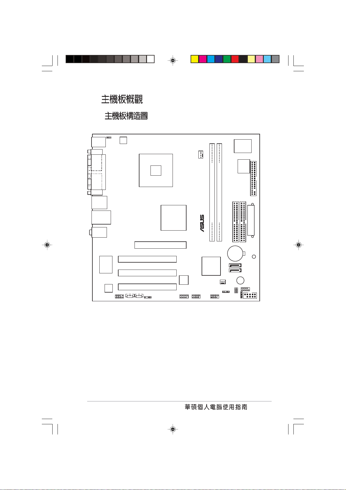
1.1
AS-D760
P5S800-VM 800MHz
LGA 775 Pentium® 4 Intel® HyperThreading Technology 3.4GHz SiS
661FX
DDR400/333 DDR SDRAM Double
Data Rate SDRAM SDRAM
2GB
¤
1.2
1.2.1
5.25
IEEE-1394
USB 2.0
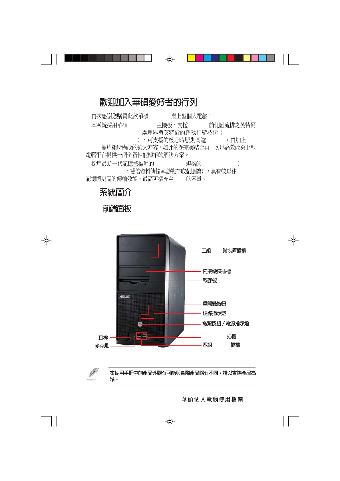
1-3
Page 14
1.2.2
PS/2
PS/2
COM1
VGA
USB
COM2
1394
LAN
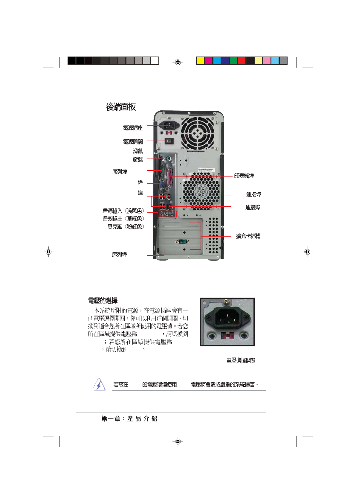
100-127V
115V 200240V 230V
230V 115V
1-4
115V/ 230V
Page 15
1.2.3
1.2.4
PS/2 USB PS/2
PS/2 USB
USB
PS/2
VGA
USB
PS/2
1394
RJ-45
AGP
PCI
1-5
Page 16
1.3
1.3.1
LGA 775 775
Intel
®
4
®
04B
LGA 775 Pentium® 4
3.4 GHz
04A
Ultra-AGP II
Pentium
800/533 MHz FSB Intel
Threading Technology
SiS® HyperStreming
®
SiS
661FX HyperStreamingTM
SiS® Ultra-AGP II
3.2GB/s DDR400 AGP8X 2.1GB/
s
Serial ATA
SiS 964 Serial ATA Serial ATA
®
Hyper
150MB
RAID
RAID 0 RAID 1
AI
Realtek ALC655 AC 97 6
5.1
1-6
SiS964 Seial ATA
Page 17
S/PDIF
S/PDIF
USB 2.0
USB 2.0 USB 1.1
12 Mbps USB 2.0 480 Mbps USB 2.
0 USB 2.0 USB 1.1
CPU ASIC
Rotation pre minute
1.3.2
CrashFree BIOS 2
CrashFree BIOS 2 BIOS
BIOS
BIOS
BIOS ROM
RPM
MyLogo2 TM
MyLogo2TM
EZ Flash BIOS
BIOS MS-DOS
EZ Flash BIOS
1-7
Page 18
1.4
1.
2.
3.
4.
5. ATX
OFF
/
1-8
®
P5S800-VM
P5S800-VM Onboard LED
SB_PWR1
ON
Standby
Power
SB_PWR1
OFF
Powered
Off
Page 19
1.5
1.5.1
PS/2KBMS
T: Mouse
B: Keyboard
COM1
VGA1
Top:1394
F_USB12
LAN_USB34
Top:LineIn
Center:Line Out
Below:Mic In
KBPWR1
PARALLELPORT
RTL8100C
ALC655
FP_AUDIO
ATX12V1
AUX1
CD1
LGA775
PCI1
PCI2
PCI3
AGP1
SPDIF1
SiS
661FX
TSB43AB22
IE1394_2
CPU_FAN1
P5S800-VM
®
DDR DIMM1 (64 bit,240-pin module)
SiS
964
CHA_FAN1
CHASSIS1
USB78USB56
DDR DIMM2 (64 bit,240-pin module)
CMOS Power
SPEAKER1
Super
PRI_IDE1
SEC_IDE1
CR2032 3V
Lithium Cell
CLRTC1
I/O
4Mb
BIOS
SATA2
SATA1
F_PANEL
PLED1
FLOPPY1
ATXPWR1
SB_PWR1
BUZZER1
COM2
1-9
Page 20
1.5.2
PS/2 PS/2 COM1/2
1.5.3
®
1-10
P5S800-VM
Page 21
1.6 CPU
LGA775 PCG 04A
04B 775 Intel Pentium 4
1.6.1
1.
•
LGA775
•
LGA775 Return
Merchandise Authorization
RMA
•
CPU CPU
•
CPU
®
P5S800-VM
P5S800-VM CPU Socket 775
1-11
Page 22
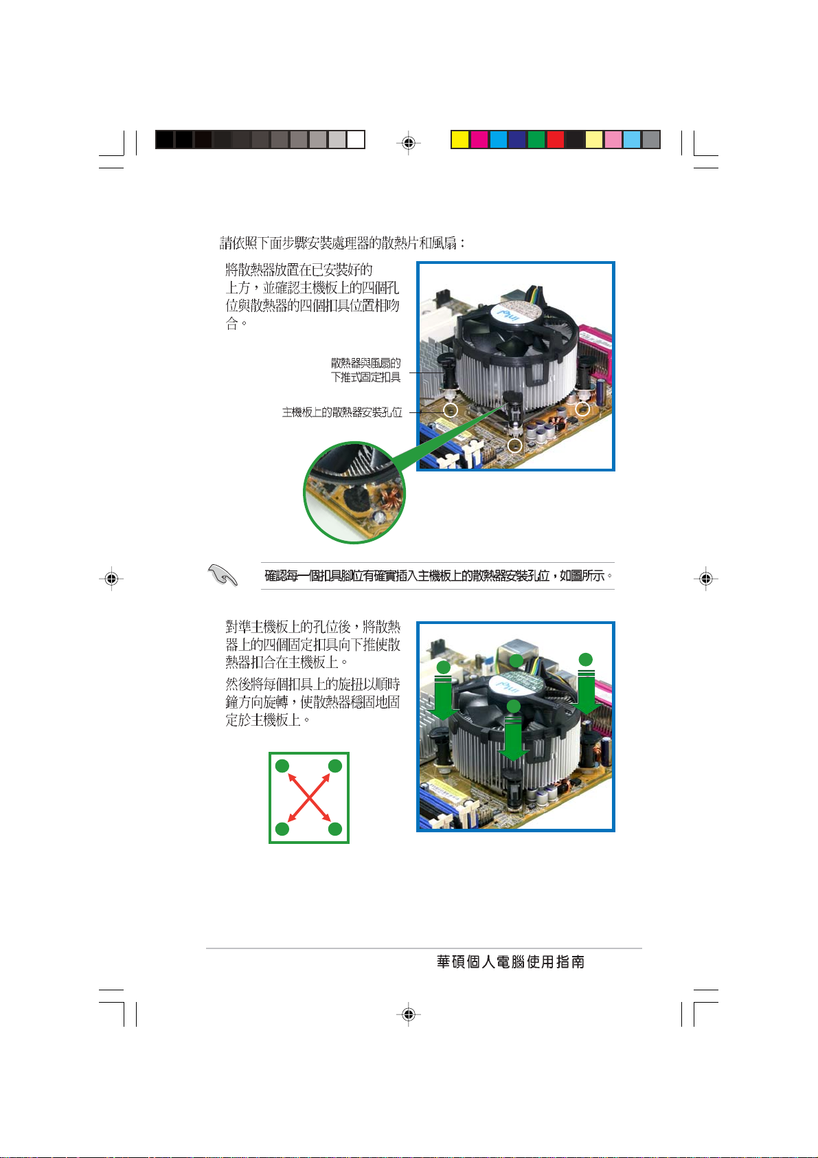
2.
CPU
A
B
CPU
CPU
3.
4. CPU
1-12
Page 23
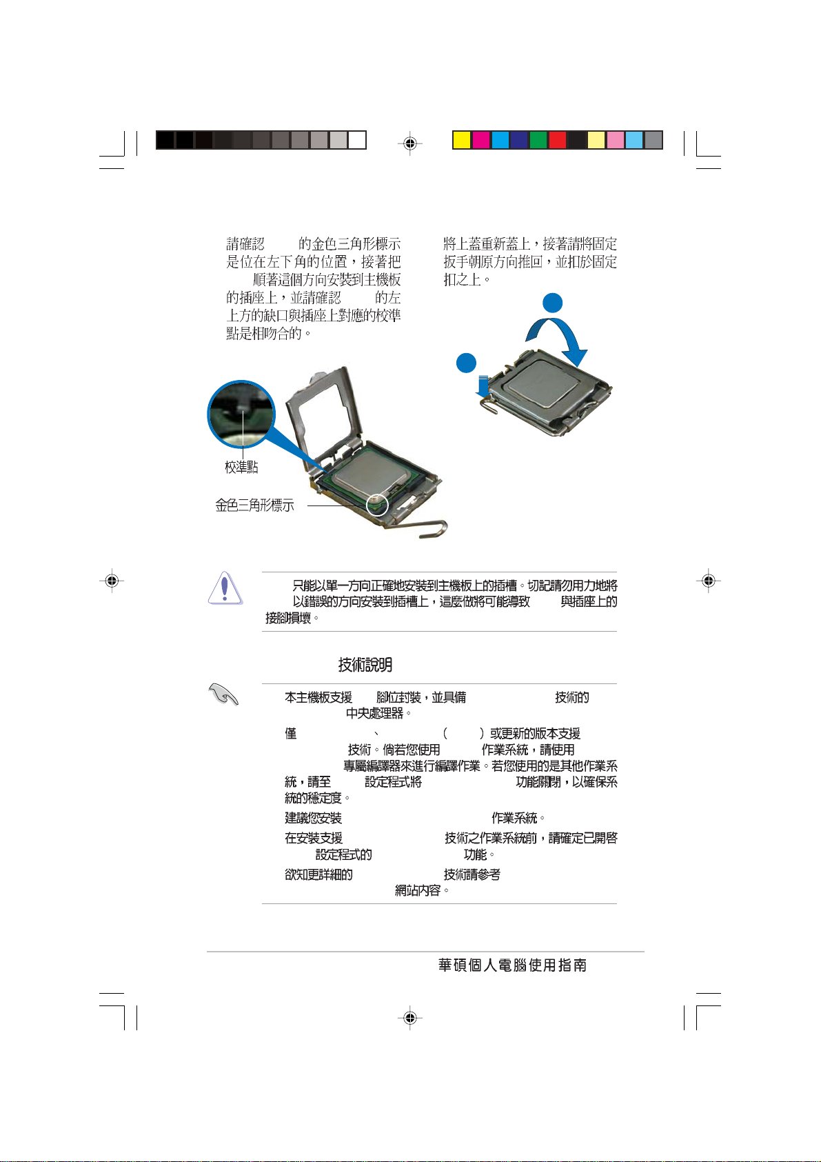
5. CPU
CPU
CPU
CPU CPU
CPU
6.
A
B
Intel Hyper-Threading
1. 775 Hyper-Threading Intel
Pentium® 4
2. Windows® XP Linux 2.4.x kernel HyperThreading
Threading
BIOS Hyper-Threading
3. Windows XP Service Pack 1
4. Hyper-Threading
BIOS Hyper-Threading
5. Hyper-Threading http://www.intel.com/
info/hyperthreading
®
Linux Hyper-
1-13
Page 24

Hyper-Threading
1. Hyper-Threading Intel® Pentium® 4
2. BIOS
Hyper-Threading Technology Enabled
Hyper-Threading CPU
3. BIOS
1.6.2
Intel® Pentium® 4 LGA775
•
•
•
CPU
Intel® Pentium® 4 LGA775
CPU Intel®
4-pin
Intel® Pentium® 4 LGA775
1-14
Page 25
1. CPU
2.
A
A
B
B
A
B
B
A
1-15
Page 26

4.
CPU_FAN1
CPU_FAN1
CPU FAN PWM
CPU FAN IN
®
P5S800-VM
P5S800-VM CPU fan connector
CPU_FAN1 CPU
Hardware monitoring errors
CPU FAN PWR
GND
1-16
Page 27
1.6.3
1. CPU
CPU_FAN1
2.
3.
A B B
A
A
B
B
A
B
A
B
A
1-17
Page 28
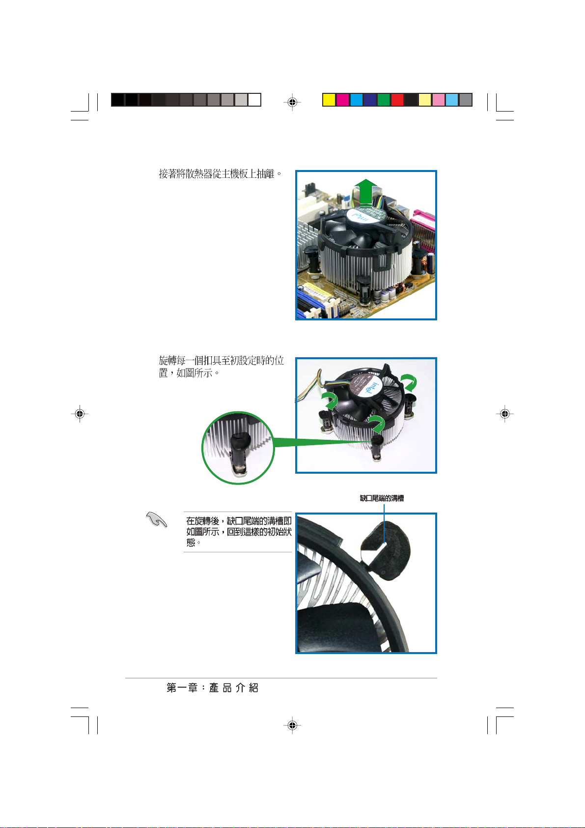
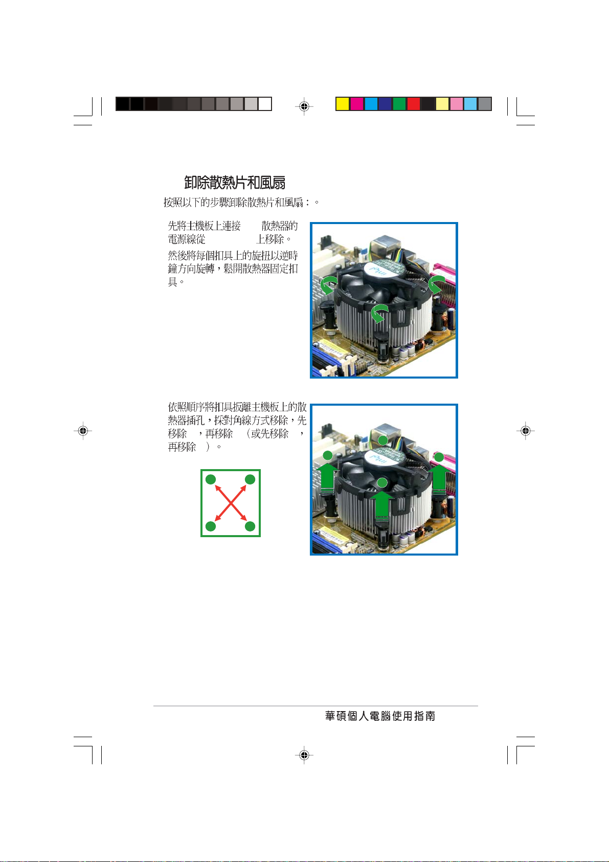
4.
5.
1-18
Page 29

1.7
1.7.1
184-pin DDR DIMM Double Data Rate
DDR DIMM
DIMM1
®
P5S800-VM
P5S800-VM 184-pin DDR DIMM sockets
1.7.2
128MB 256MB 512MB 1GB unbuffered non-
ECC DDR DDR DIMM
DIMM2
DDR 1
1-19
Page 30

1 DDR400
Side(s) A* B*
256MB Kingston KVR333X64C25/256 Kingston SS D3208DH1T-6
256MB Kingston KVR333X64C25/256 Hynix SS HY5DU56822BT-J
512MB Kingston KVR333X64C25/512 Hynix DS HY5DU56822BT-D43
512MB Kingston KVR333X64C25/512 Hynix DS HY5DU56822BT-J
512MB Kingston KVR400X643A/512 Hynix DS HY5DU56822BT-D43
512MB Kingston KVR400X64C3A/512 Kingston DS D3208DL3T-5
256MB Kingston KVR400X64C3A/256 Hynix SS HY5DU56822BT-D43
256MB Infineon HYS64D64320GU-5-C Infineon SS HYB25D256800CE-5C
512MB Infineon HYS64D32300GU-5-C Infineon DS HYB25D256800CE-5C
256MB Infineon HYS64D64320GU-5-C Infineon SS HYB25D256800CE-5C
512MB Infineon HYS64D64320GU-6-C Infineon DS HYB25D256800CE-6C
512MB HY DDR400-512 Hynix DS HY5DU56822BT-D43
256MB HY DDR266-256 Hynix SS HY5DU56822AT-H
256MB HY DDR333-256 Hynix SS HY5DU56822BT-J
512MB HY DDR333-512 Hynix DS HY5DU56822BT-J
256MB Corsair VS256MB400 Value select SS VS32M8-5 2B0409
512MB Corsair VS512MB400 Value select DS VS32M8-5 2B0412
256MB Corsair VS256MB333 Samsung SS K4H5608380-TCB3
512MB Micron MT16VDDT6464AG-335GB Micron DS MT46V32M8-G
256MB Micron MT8VDDT3264AG-335GB Micron SS MT46V32M8-G
256MB Micron MT8VDDT3264AG-40BGB Micron SS MT46V32M8-G
256MB Samsung M368L3223FTN-CB3 Samsung SS K4H560838F-TCB3
512MB Samsung M368L6423FTN-CB3 Samsung DS K4H5608838F-TCB3
256MB Winbond U24256ADWBG6H20 Winbond SS W942508CH-5
256MB Winbond U24256AAWBG6H20 Winbond SS W942508CH-6
512MB Winbond DDR333-512 Winbond DS W942508BH-6
256MB Transcend DDR400-256 Mosel SS V58C2256804SAT5B
512MB Transcend DDR400-512 Samsung DS K4H560838F-TCCC
256MB Transcend DDR333-256 Mosel SS V58C2256804SAT6
512MB Transcend DDR333-512 Hynix DS HY5DU56822CT-J
512MB Kingmax MPXC22D-38KT3R Kingmax DS KDL388P4EA-50
256MB Apacer 77.10628.10A Apacer SS AM3A5608AIT-6B
256MB Apacer 77.10628.56G Mosel SS V58C2256804SAT6
256MB Apacer 77.10636.56G Mosel SS V58C2256804SAT5B
512MB Apacer 77.10736.11G Infineon DS HYB25D256800BT-5B
512MB Smart U24512ADSRG6H20 Smart DS D32M8XS50H3X4AMV
1G Twinmos M2S5016AJAMC5G0811A-J Micron DS MT46V64M8TG-6T
256MB Twinmos M2S9109BFAPS9F0811A-T PSC SS A2S56D30ATP
••
••
••
••
••
••
••
••
••
••
••
••
••
••
••
••
••
••
••
••
••
••
••
••
••
••
••
••
Side(S) SS - DS -
••
••
••
••
••
••
••
••
••
••
1-20
A B -
http://tw.asus.com
Page 31

1.7.3
1.
2
3
DDR
2.
3.
1.7.4
1
1
DDR DIMM
2
1
1
2
1.
1
1
DDR
2.
1-21
Page 32

1.8
1.8.1
1.
2.
3.
4.
5.
6.
/
1.8.2
1. BIOS
BIOS
2. IRQ
3.
1-22
Page 33

IRQ
01
12
2 N/A IRQ#9
311 COM 2 *
412 COM 1 *
513 PCI *
614
715 LPT 1 *
83 CMOS/
94 PCI *
10 5 PCI *
11 6 PCI *
12 7 PS/2 *
13 8
14 9 IDE
15 10 IDE
*
AB CDEFGH
IRQ
PCI
IRQ IRQ
1-23
Page 34

1.8.3 PCI
USB PCI
PCI
PCI
1.8.4 AGP
8X AGP AGP
AGP
AGP
32 PCI
SCSI
PCI
AGP Accelerated Graphics Port
+1.5V AGP 3.3V AGP
1-24
®
P5S800-VM
Keyed for 1.5v
P5S800-VM Accelerated Graphics Port (AGP)
Page 35

1.9
1. CMOS CLRTC1
CMOS
CMOS
1.
2.
3. CLRTC1 [1-2] [2-3]
CMOS [1-2]
4.
5.
6. Del BIOS
BIOS
CMOS CLRTC
®
P5S800-VM
P5S800-VM Clear RTC RAM
BIOS
CLRTC1
2
1
C.P.R CPU
3
2
NormalClear CMOS
(Default)
1-25
Page 36

2. 3-pin KBPWR1
+5VSB [1-2]
+5V
1A/+5VSB BIOS
KBPWR1
2312
®
P5S800-VM
P5S800-VM Keyboard power setting
+5V +5VSB
(Default)
1.10
1.10.1
[2-3]
1
12
11
2 4
1. PS/2 PS/2
2. 25-pin
3. 1394 1394
1-26
10
3
5
6
7
9
8
Page 37

4. RJ-45 LAN Local
Area Network
ACT/LINK SPEED
10Mbps
100Mbps
5. DVD
6.
7.
2 4 6
SPEEDACT/LINK
8. USB 2.0 3 4 USB
USB 2.0
9. USB 2.0 1 2 USB
USB 2.0
10. VGA 15-pin VGA
VGA
11. 9-pin
12. PS/2 PS/2
1-27
Page 38

1.10.2
1. 34-1 pin FLOPPY1
®
P5S800-VM
P5S800-VM Floppy disk drive connector
FLOPPY1
NOTE: Orient the red markings on
the floppy ribbon cable to PIN 1.
Pin 1
PIN 1
1-28
Page 39

2. IDE 40-1 pin PRI_IDE1
Ultra DMA 133/100/66 Ultra DMA 133/
100/66 IDE
Master UltraDMA 133/
100/66 IDE
Slave UltraDMA133/100/66 IDE
Slave
UltraDMA 133/100/66 UltraDMA133/
100/66
•
•
IDE UltraATA
80 IDE UltraDMA 133/100/66
IDE
®
P5S800-VM
P5S800-VM IDE connectors
SEC_IDE1
PIN 1
NOTE: Orient the red markings
(usually zigzag) on the IDE
ribbon cable to PIN 1.
Pin 1
PRI_IDE1
1-29
Page 40

3. Serial ATA 7-pin SATA1, SATA2
Serial ATA
Serial ATA SiS 964 RAID
RAID 0 RAID 1
GND
GND
RSATA_RXP2
RSATA_RXN2
®
P5S800-VM
SATA2
RSATA_RXP1
GND
GND
RSATA_RXN1
RSATA_TXN2
RSATA_TXN1
RSATA_TXP2
RSATA_TXP1
Serial ATA
GND
GND
P5S800-VM SATA connectors
Serial ATA
Serial ATA RAID RAID 0, 1 Windows
•
XP
Windows 2000
•
Serial ATA Windows XP Service Pack 1
Windows 2000 Service Pack 4
4. 4-pin SPEAKER1
®
P5S800-VM
P5S800-VM Speaker out connector
SATA1
SPEAKER1
1
Speak Out
GND
GND
+5V
1-30
Page 41

5. / 4-pin CPU_FAN1, 3-pin CHA_FAN1
350 740 8.88 1 2.22
26.64 /+12
+12V
GND
CPU_FAN1
CPU FAN PWM
CPU FAN IN
CPU FAN PWR
®
P5S800-VM
P5S800-VM Fan connectors
GND
CHA_FAN1
GND
Rotation
+12V
6. 4-1 pin SPDIF1
S/PDIF S/
PDIF
®
P5S800-VM
P5S800-VM Digital audio connector
+5V
SPDIFOUT
SPDIF1
GND
1-31
Page 42

7. 20-pin ATXPWR1, 4-pin ATX12V1
ATX +12V
•
20-pin ATX 12V PSU
300W
•
4-pin ATX +12V
•
®
P5S800-VM
P5S800-VM ATX power connectors
8. 3-1 pin PLED1
3-1 pin
ATX12V1
ATXPWR1
+12V DC GND
+12V DC GND
+12.0VDC
+5VSB
PWR_OK
COM
+5.0VDC
COM
+5.0VDC
COM
+3.3VDC
+3.3VDC
+5.0VDC
+5.0VDC
-5.0VDC
COM
COM
COM
PS_ON#
COM
-12.0VDC
+3.3VDC
1-32
®
P5S800-VM
P5S800-VM PLED connector
PLED1
1
PLEDNC
PLED+
Page 43

9. 4-pin CD1, AUX1
TV MPEG
®
P5S800-VM
Left Audio Channel
AUX1 (White) CD1 (Black)
P5S800-VM Internal audio connectors
10. USB 10-1 pin USB56, USB78
USB
USB USB
USB 2.0 480 Mbps
Ground
Right Audio Channel
Ground
Left Audio Channel
Right Audio Channel
®
P5S800-VM
P5S800-VM USB 2.0 connectors
1394 USB56 USB78
USB56
1
USB+5V
USB_P6-
USB_P6+
USB+5V
USB_P5-
USB_P5+
GND
GND
NC
USB78
1
USB+5V
USB_P8-
USB_P8+
USB+5V
USB_P7-
USB_P7+
GND
GND
NC
1-33
Page 44

11. 10-1 pin FP_AUDIO1
/
LINE_OUT_R/BLINE_OUT_R
LINE_OUT_L/BLINE_OUT_L
®
P5S800-VM
FP_AUDIO1
P5S800-VM Front panel audio connector
12. COM2 10-1 pin COM2
BIOS
COM2 COM2
COM2 COM2
AGND
MIC2
+5VA
MICPWR
BLINE_OUT_L
BLINE_OUT_R
NC
Line out_L
Line out_R
1-34
®
P5S800-VM
P5S800-VM Serial port connector
COM2
PIN 1
Page 45

13. 20-pin PANEL
®
P5S800-VM
P5S800-VM System panel connector
2-pin PLED
IDE 2-pin HD_LED
IDE_LED IDE
IDE
/ 2-pin PWRBTN
BIOS
F_PANEL1
PLED PWRBTN*
PLED-
PWR
PLED+
GNDReset
Ground
HDLED-
HDLED+
HDLED RESET
2-pin RESET
Reset
1-35
Page 46

1-36
Page 47

BIOS
Page 48

2.1 BIOS
2.1.1
2.1.2 AFUDOS BIOS
2.1.3 EZ Flash BIOS
2.1.4 CrashFree BIOS 2 BIOS
2.1.5
2.2 BIOS
...................................................................................
.....................................................................................
2.3 Main Menu
2.4 Advanced menu
2.4.1 JumperFree JumperFree Configuration
2.4.2 CPU Configuration
2.4.3 Chipset
2.4.4 OnBoard Devices Configuration
2.4.5 PCI PCI PnP
2.4.6 USB USB Configuration
...................................................................
...............................................................................
......................................................
................................................
.................................
.........................................................................
..............................................................
............................
..............................................
.....................................................................
......................
....................................................
..........................................
2.4.7 Instant Music Configuration
2.5 Power menu
2.5.1 Suspend Mode [Auto]
2.5.2 ACPI 2.0 Support [No]
2.5.3 ACPI APIC Support [Enabled]
2.5.4 APM Configuration
2.5.5 Hardware Monitor
2.6 Boot menu
2.6.1 Boot Device Priority
2.6.2 Boot Settings Configuration
2.6.3 Boot Settings Configuration
2.6.4 Security
2.7 BIOS Exit menu
....................................................................
......................................................................
....................................................................
........................................................
..................................
............................................
......................................................................
........................................
.....................................
.............................
................................................................
............................................................
.........
2-3
2-3
2-4
2-5
2-7
2-9
2-12
2-15
2-18
2-18
2-20
2-21
2-22
2-24
2-25
2-26
2-27
2-27
2-27
2-27
2-28
2-29
2-31
2-31
2-31
2-32
2-33
2-35
2-2
BIOS
Page 49

2.1 BIOS
BIOS Basic Input/Output
System
1. ASUS AFUDOS DOS BIOS
2. ASUS EZ Flash Power-On Self Test
POST BIOS
3. ASUS CrashFree BIOS 2 BIOS
BIOS
4. ASUS Update Windows BIOS
BIOS
BIOS AFUDOS
BIOS
2.1.1
1.
DOS
a. 1.44MB
b. DOS format A:/S Enter
Windows XP
a. 1.44MB
b. Windows
c. 3 1/2
d. File Format Format 3 1/2 Floppy
Disk
e. Create a MS-DOS startup disk
Windows 2000
a. 1.44MB
b. Windows 2000
c. Run
d. D:\bootdisk\makeboot a: D
e. Enter
2. BIOS
2-3
Page 50

2.1.2 EZ Flash BIOS
EZ Flash BIOS
DOS EZ Flash BIOS
Power-On Self Test POST
Alt + F2 EZ Flash
EZ Flash BIOS
1. tw.asus.com BIOS
2.
3. POST Alt + F2
EZ Flash
EZFlash starting BIOS update
Checking for floppy...
4. BIOS
EZ Flash BIOS
EZFlash starting BIOS update
Checking for floppy...
Floppy found!
Reading file “P5S800VM.rom”. Completed.
Start erasing.......|
Start programming...|
Flashed successfully. Rebooting.
2-4
•
•
not found
BIOS
BIOS
Floppy
BIOS
P5S800VM.ROM not found
BIOS P5S800VM.ROM
Page 51

2.1.3 AFUDOS BIOS
AFUDOS DOS BIOS
BIOS AFUDOS BIOS
BIOS
BIOS
•
600KB
BIOS
•
BIOS
1. AFUDOS afudos.
exe
2. DOS
filename
A:\>afudos /oOLDBIOS1.ROM
3. Enter BIOS
A:\>afudos /oOLDBIOS1.ROM
AMI Firmware Update Utility - Version 1.10
Copyright (C) 2002 American Megatrends, Inc. All rights reserved.
Reading flash ..... done
Write to file ...ok
A:\>
BIOS DOS
2-5
Page 52

BIOS
AFUDOS BIOS
1. tw.asus.com BIOS
BIOS
2. AFUDOS.EXE BIOS
3. DOS
filename
BIOS
A:\>afudos /iP5S800VM.ROM
4. AFUDOS BIOS
A:\>afudos /iP5S800VM.ROM
AMI Firmware Update Utility - Version 1.19(ASUS V2.07(03.11.24BB))
Copyright (C) 2003 American Megatrends, Inc. All rights reserved.
Reading file ..... done
Erasing flash .... done
Writing flash .... 0x0008CC00 (9%)
BIOS
5. BIOS DOS
A:\>afudos /iP5S800VM.ROM
AMI Firmware Update Utility - Version 1.19(ASUS V2.07(03.11.24BB))
Copyright (C) 2003 American Megatrends, Inc. All rights reserved.
Reading file ...... done
Erasing flash ..... done
Writing flash ..... 0X0008CC00 (9%)
Verifying flash ... done
A:\>
2-6
BIOS
Page 53

2.1.4 CrashFree BIOS 2 BIOS
CrashFree BIOS 2 BIOS
BIOS BIOS
1. BIOS
BIOS
2. BIOS
BIOS
BIOS
1.
2. BIOS
3.
BIOS
Bad BIOS checksum. Starting BIOS recovery...
Checking for floppy...
BIOS
Bad BIOS checksum. Starting BIOS recovery...
Checking for floppy...
Floppy found!
Reading file “P5S800VM.ROM”. Completed.
Start flashing...
BIOS
4.
2-7
Page 54

BIOS
BIOS
1.
2.
3.
BIOS
Bad BIOS checksum. Starting BIOS recovery...
Checking for floppy...
4.
Bad BIOS checksum. Starting BIOS recovery...
Checking for floppy...
Floppy not found!
Checking for CD-ROM...
CD-ROM found!
Reading file “P5S800VM.ROM”. Completed.
Start flashing...
BIOS
5. BIOS
2-8
BIOS BIOS
http://tw.asus.com BIOS
BIOS
Page 55

2.1.5
BIOS
1. BIOS
2. BIOS
3. BIOS BIOS
4. BIOS
5. BIOS
1.
2.
3-4
3.
Windows
ISP
BIOS
2-9
Page 56

BIOS
1.
2.
BIOS
3. FTP
2-10
BIOS
Page 57

4. BIOS
Next
5.
BIOS
BIOS
BIOS BIOS
BIOS BIOS
1.
2.
3. BIOS
4.
BIOS
2-11
Page 58

2.2 BIOS
BIOS Basic Input and Output System
BIOS
BIOS
BIOS
RUN SETUP BIOS
BIOS
Flash ROM BIOS Flash
ROM
BIOS BIOS
BIOS
CMOS RAM
BIOS
POST Power-On Self Test
Delete Delete
Reset Ctrl + Alt
+ Delete
BIOS
2-12
1. BIOS
BIOS
2.7 BIOS Load Setup
Defaults
2. BIOS
3. http://tw.asus.com BIOS
BIOS
BIOS
Page 59

2.2.1 BIOS
System Time [11:51:19]
System Date [Thu 10/07/2004]
Legacy Diskette A [1.44M, 3.5 in]
Primary IDE Master : [ST320413A]
Primary IDE Slave : [ASUS CD-S360]
Secondary IDE Master : [Not Detected]
Secondary IDE Slave : [Not Detected]
OnChip SATA Controller [Enabled]
System Information
2.2.2
BIOS
BIOS
Use [ENTER], [TAB]
or [SHIFT-TAB] to
select a field.
Use [+] or [-] to
configure system time.
APM
2.2.3
2-13
Page 60

2.2.4
Advanced Power Boot Exit
2.2.5
2.2.6
2.2.7
Enter
2.2.8
System Time [11:10:19]
System Date [Thu 03/27/2003]
Legacy Diskette A [1.44M, 3.5 in]
Language [English]
Primary IDE Master :[ST320413A]
Primary IDE Slave :[ASUS CD-S340]
Secondary IDE Master :[Not Detected]
Secondary IDE Slave :[Not Detected]
Third IDE Master :[Not Detected]
Fourth IDE Master :[Not Detected]
IDE Configuration
System Information
Enter
Advanced Chipset settings
WARNING: Setting wrong values in the sections below
may cause system to malfunction.
Configure DRAM Timing by SPD [Enabled]
Memory Acceleration Mode [Auto]
DRAM Idle Timer [Auto]
DRAm Refresh Rate [Auto]
Graphic Adapter Priority [AGP/PCI]
Graphics Aperture Size [ 64 MB]
Spread Spectrum [Enabled]
ICH Delayed Transaction [Enabled]
MPS Revision [1.4]
Use [ENTER], [TAB]
or [SHIFT-TAB] to
select a field.
Use [+] or [-] to
configure system time.
Select Screen
Select Item
+- Change Field
Tab Select Field
F1 General Help
F10 Save and Exit
ESC Exit
Select Screen
Select Item
+- Change Option
F1 General Help
F10 Save and Exit
ESC Exit
2-14
2.2.9
BIOS
Page 61

2.3 Main Menu
BIOS
2.2.1 BIOS
System Time [11:51:19]
System Date [Thu 10/07/2004]
Legacy Diskette A [1.44M, 3.5 in]
Language [English]
Primary IDE Master : [ST320413A]
Primary IDE Slave : [ASUS CD-S360]
Secondary IDE Master : [Not Detected]
Secondary IDE Slave : [Not Detected]
OnChip SATA Controller [Native Mode]
System Information
2.3.1 System Time [XX:XX:XXXX]
00 23 00 59 00 59 Tab
Tab + Shift
2.3.2 System Date [Day XX/XX/XXXX]
1 12 1 31 2099 Tab Tab +
Shift
2.3.3 Legacy Diskette A [1.44M, 3.5 in.]
[Disabled] [360K, 5.25 in.]
[1.2M, 5.25 in.] [720K, 3.5 in.] [1.44M, 3.5 in.] [2.88M, 3.5 in.]
2-15
Page 62

2.3.4 IDE Primary and Secondary
IDE Master/Slave
BIOS IDE
IDE Enter
Primary IDE Master
Device : Hard Disk
Vendor : ST320413A
Size : 20.0GB
LBA Mode : Supported
Block Mode : 16 Sectors
PIO Mode : 4
Async DMA : MultiWord DMA-2
Ultra DMA : Ultra DMA-5
SMART Monitoring: Supported
Type [Auto]
LBA/Large Mode [Auto]
Block(Multi-sector Transfer) [Auto]
PIO Mode [Auto]
DMA Mode [Auto]
Smart Monitoring [Auto]
32Bit Data Transfer [Disabled]
Device Vendor Size LBA Mode Block
PIO Mode Async DMA Ultra DMA SMART monitoring
Mode
BIOS N/A
Type [Auto]
IDE Auto
IDE CDROM IDE
ARMD ATAPI IDE
ZIP LS-120 MO [Not
Installed] [Auto] [CDROM] [ARMD]
LBA/Large Mode [Auto]
LBA [Auto]
LBA LBA
[Disabled] [Auto]
Block (Multi-sector Transfer) [Auto]
[Disabled]
[Disabled] [Auto]
PIO Mode [Auto]
PIO [Auto] [0] [1] [2] [3] [4]
2-16
BIOS
[Auto]
Page 63

DMA Mode [Auto]
DMA [Auto] [SWDMA0] [SWDMA1] [SWDMA2]
[MWDMA0] [MWDMA1] [MWDMA2] [UDMA0] [UDMA1] [UDMA2]
[UDMA3] [UDMA4] [UDMA5]
SMART Monitoring [Auto]
Smart Monitoring, Analysis, and
Reporting Technology
[Auto] [Disabled] [Enabled]
32Bit Data Transfer [Disabled]
32 [Disabled] [Enabled]
2.3.5 Onchip SATA Controller [Native Mode]
Serial ATA
[Disabled] [Native Mode][Raid Mode] Raid Mode
Raid
2.3.6 System Information
BIOS
AMIBIOS
Version : 08.00.10
Build Date : 10/07/04
Processor
Type : Genuine Intel(R) CPU 3.20GHz
Speed : 2800 MHz
Count : 1
System Memory
Size : 512MB
AMI BIOS
BIOS
Processor
System Memory
2-17
Page 64

2.4 Advanced menu
JumperFree Configuration
CPU Configuration
Chipset
Onboard Devices Configuration
PCI PnP
USB Configuration
Instant Music Configuration
Configure CPU.
Select Screen
Select Item
Enter Go to Sub-screen
F1 General Help
F10 Save and Exit
ESC Exit
2.4.1 JumperFree JumperFree
Configuration
Configure System Frequency/Voltage
AI Overclocking [Standard]
Spread Spectrum [Enabled]
DRAM Frequency [Auto]
CPU Lock Free [Auto]
AI Overclock Tuner [Standard]
Select the target CPU
frequency, and the
relevant parameters
will be auto-adjusted.
Frequencies higher
than CPU manufacturer
recommends are not
guaranteed to be
stable. If the system
becomes unstable,
return to the default.
10%][Overclock 20%][Overclock 30%]
2-18
BIOS
[Manual] [Standard][Overclock 5%][Overclock
Page 65

CPU Frequency [XXX]
BIOS + -
100 400 MHz
AGP/PCI Frequency [Auto]
AGP/PCI [Auto] [66.6/33.3]
[75.0/37.5] [85.7/42.8]
Spread Spectrum [Enabled]
spectrum
[Disabled] [Enabled]
DRAM Frequency [Auto]
[333MHz] [400MHz] [Auto]
CPU Lock Free [Auto]
[Auto][Disabled] [Enabled]
PCI
CPU Speed
clock generator spread
[200MHz] [266MHz]
2-19
Page 66

2.4.2 CPU Configuration
Configure Advanced CPU settings
Manufacturer: Intel
Brand String: Genuine Intel(R) CPU 2.80GHz
Frequency : 2806 MHz
FSB Speed : 800 MHz
Cache L1 : 16 KB
Cache L2 : 1024 KB
Cache L3 : 0 KB
Ratio Status: Unlocked
Ratio Actual Value : 14
CPU Lock Free [Auto]
Microcode Updation [Enabled]
Max CPUID Value Limit: [Disabled]
Enhanced C1 Control [Auto]
CPU Internal Thermal Control [Auto]
Hyper Threading Technology [Enabled]
CPU Lock Free [Auto]
[Auto][Disabled] [Enabled]
Microcode Updation [Enabled]
[Disabled] [Enabled]
Max CPUID Value Limit [Disabled]
CPUID
[Enabled] [Disabled] [Enabled]
microcode updation
Select Screen
Select Item
+- Change Option
F1 General Help
F10 Save and Exit
ESC Exit
Enhanced C1 Control [Auto]
[Auto] BIOS C1E
C1E
[Auto] [Disabled] Intel
CPU Internal Thermal Control [Auto]
[Disabled] [Auto] Intel
Hyper-Threading Technology [Enabled]
[Disabled] [Enabled]
2-20
BIOS
Hyper-Threading
Page 67

2.4.3 Chipset
Enter
NorthBridge SiS661FX Configuration
SouthBridge SiS964 Configuration
SiS661FX NorthBridge SiS661FX
Configuration
Primary Graphics Adapter [PCI]
MA 1T/2T Select [Auto]
Performance Mode select [Disabled]
DRAM CAS# Latency [By SPD]
DRAM Precharge Delay [Auto]
DRAM RAS# to CAS# Delay [Auto]
DRAM RAS# Precharge [Auto]
Graphic Win Size [ 64MB]
AGP Fast Write Control [Disabled]
Share Memory Size [ 32MB]
Primary Graphics Adapter [PCI]
[PCI][OnBoard AGP]
MA 1T/2T Select [Auto]
[Auot] [MA 2T] [MA] [1T]
[AGP]
Performance Mode Select [Disabled]
[Disabled] [Enabled]
DRAM CAS# Latency [By SPD]
[By SPD] [2T] [2.5T] [3T]
DRAM Precharge Delay [Auto]
[Auto] [6T] [7T] [5T] [4T] [8T] [9T]
DRAM RAS# to CAS# Delay [Auto]
[Auto] [3T] [2T] [4T] [5T]
DRAM RAS# Precharge [Auto]
precharge
[Auto] [3T] [2T] [4T] [5T]
/
2-21
Page 68

Graphic Win Size [64MB]
AGP [32MB]
[64MB] [128MB]
AGP Fast Write Control [Disabled]
AGP [Disabled]
[Enabled]
Share Memory Size [32MB]
[16MB] [32MB]
[64MB] [128MB] [Disabled]
SiS964 SourthBridge SiS964 Configuration
Onboard AC97 Device [Enabled]
Onboard AC97 Device [Enabled]
AC97
[Disabled] [Enabled]
2.4.4 OnBoard Devices
Configuration
Configure Win637 Super IO Chipset
Serial Port1 Address [3F8/IRQ4]
Serial Port2 Address [2F8/IRQ3]
Parallel Port Address [378]
Parallel Port Mode [Normal]
ECP Mode DMA Channel [DMA3]
Parallel Port IRQ [IRQ7]
Onboard RTL8100C LAN DEVICE [Enabled]
Onboard LAN Boot ROM [Disabled]
Serial Port1 Address [3F8/IRQ4]
COM 1 [Disabled] [3F8/IRQ4]
[3E8/IRQ4] [2E8/IRQ3]
2-22
BIOS
Select Screen
Page 69

Serial Port2 Address [2F8/IRQ3]
COM 2 [Disabled] [2F8/IRQ3]
[3E8/IRQ4] [2E8/IRQ3]
Parallel Port Address [378]
[278] [3BC]
Parallel Port Mode [ECP]
Parallel Port [Normal] [Bi-directional]
[EPP] [ECP]
EPP Version [1.9]
[EPP]
Parallel Port EPP [1.9] [1.7]
ECP Mode DMA Channel [DMA3]
[ECP]
Parallel Port ECP DMA [DMA0] [DMA1] [DMA3]
Parallel Port IRQ [IRQ7]
[IRQ5] [IRQ7]
Onboard RTL8100C LAN DEVICE [Enabled]
RTL8100C
[Disabled] [Enabled]
[Disabled] [378]
Onboard LAN Boot ROM [Disabled]
[Enabled]
[Disabled]
2-23
Page 70

2.4.5 PCI PCI PnP
PCI/PnP PCI/PnP
IRQ DMA
Advanced PCI/PnP Settings
WARNING: Setting wrong values in below sections
may cause system to malfunction.
Plug And Play O/S [No]
PCI Latency Timer [64]
Allocate IRQ to PCI VGA [Yes]
Palette Snooping [Disabled]
PCI IDE BusMaster [Enabled]
IRQ3 [PCI Device]
IRQ4 [PCI Device]
IRQ5 [PCI Device]
IRQ7 [PCI Device]
IRQ9 [PCI Device]
IRQ10 [PCI Device]
IRQ11 [PCI Device]
IRQ14 [PCI Device]
IRQ15 [PCI Device]
Plug And Play O/S [No]
[No] BIOS
[Yes] [No] [Yes]
Select Screen
Select Item
+- Change Option
F1 General Help
F10 Save and Exit
ESC Exit
PCI Latency Timer [64]
PCI [32] [64] [96]
[128] [160] [192] [224] [248]
Allocate IRQ to PCI VGA [Yes]
[Yse] BIOS PCI IRQ
[No] [Yes]
Palette Snooping [Disabled]
VGA [Disabled]
[Disabled] [Enabled]
2-24
BIOS
PCI IRQ
MPEG
[Enabled]
Page 71

PCI IDE BusMaster [Enabled]
BIOS PCI
IDE [Disabled] [Enabled]
IRQ-xx [PCI Device]
[PCI Device] IRQ PCI/PnP
[Reserved] IRQ ISA
[PCI Device] [Reserved]
2.4.6 USB USB Configuration
USB
Enter
Onboard SiS USB1.1 DEVICE [Enabled]
Onboard SiS USB2.0 DEVICE [Enabled]
USB Devices Enabled: None
Module Version - 2.23.2-9.4
USB Device Enabled : None
Legacy USB Support [Auto]
USB 2.0 Controller Mode [Enabled]
Stop EHCT HC in OHCT handover [Enabled]
Onboard SiS USB1.1 DEVICE [Enabled]
SiS USB 1.1
[Diabled] [Enabled]
Onboard SiS USB2.0 DEVICE [Enabled]
SiS USB 2.0
[Diabled] [Enabled]
1. Module Version USB Device Enabled
USB None
2. Windows 98SE Windows ME
[Disabled]
Legacy USB Support [Auto]
USB [Auto]
USB USB
USB USB
[Disabled] [Enabled] [Auto]
Enables USB host
controllers.
Select Screen
[Disabled]
2-25
Page 72

USB 2.0 Controller Mode [HiSpeed]
USB 2.0 HiSpeed
480 Mbps Full Speed 12 Mbps [HiSpeed] [Full
Speed]
Stop EHCT HC in OHCT handover [Enabled]
OHCI OS handover call EHCI host controller
EHCI host
[Diabled] [Enabled]
2.4.7 Instant Music
Configuration
Instant Music Option
Instant Music [Enabled]
Instant Music [Enabled]
BIOS Instant Music
[Disabled] [Enabled]
Instant Music PS/2
Instant Music CD-ROM Drive [IDE Secondary Master]
[IDE Primary Master] [IDE Primary Slave] [IDE Secondary Master] [IDE Secondary
Slave]
Instant Music [Enabled]
2-26
BIOS
Page 73

2.5 Power menu
Enter
APM ACPI
Suspend Mode [Auto]
ACPI 2.0 Support [No]
ACPI APIC Support [Enabled]
APM Configuration
Hardware Monitor
2.5.1 Suspend Mode [Auto]
Suspend [S1 POS only]
[Auto] [S3 only]
2.5.2 ACPI 2.0 Support [No]
ACPI 2.0 [No] [Yes]
2.5.3 ACPI APIC Support [Enabled]
ACPI APIC RSDT
[Disabled] [Enabled]
Configure CPU.
2-27
Page 74

2.5.4 APM Configuration
Power Button Mode [On/Off]
Restore on AC Power Loss [Always OFF]
Power On By PS/2 Keyboard [Disabled]
Power On By PS/2 Mouse [Disabled]
Power On By PCI Devices [Disabled]
Power On By External Modems [Disabled]
Power On By RTC Alarm [Disabled]
Power Button Mode [On/Off]
[On/Off] [Suspend]
Restore on AC Power Loss [Always OFF]
[Power Off]
[Power On] [Last
State]
OFF] [Always On] [Keep Previous State]
Power On By PS/2 Keyboard [Disabled]
1 5VSB
[Disabled] [Space Bar] [Ctrl-Esc] [Power Key]
Power On By PS/2 Mouse [Disabled]
[Enabled] PS2
ATX 1 5VSB
[Disabled] [Enabled]
Enabled or disable
APM.
[Always
ATX
Power On By PCI Devices [Disabled]
[Enabled] PCI
ATX 1
5VSB [Disabled] [Enabled]
Power On By External Modems [Disabled]
[Disabled] [Disabled]
[Enabled]
2-28
BIOS
[Enabled]
Page 75

Power On By RTC Alarm [Disabled]
RTC [Enabled]
RTC Alarm Date RTC Alarm Hour RTC Alarm Minute RTC
Alarm Second
[Disabled] [Enabled]
2.5.5 Hardware Monitor
Hardware Monitor
CPU Temperature [51ºC/122.5ºF]
MB Temperature [41ºC/105.5ºF]
CPU Fan Speed [3813 RPM]
CPU Q-Fan Control [Enabled]
CPU Q-Fan Mode [PWM]
CPU/Chassis Fan Ratio [30%]
CPU Target Temperature [65ºC]
Chassis Fan Speed [N/A]
Chassis Q-Fan Control [Enabled]
VCORE Voltage [ 1.320V]
3.3V Voltage [ 3.345V]
5V Voltage [ 5.094V]
12V Voltage [11.880V]
CPU Temperature [xxx /xxx ]
MB Temperature [xxx
/xxx ]
Select Screen
Select Item
+- Change Option
F1 General Help
F10 Save and Exit
ESC Exit
CPU Fan Speed [xxxxRPM] or [N/A]
RPM Rotations Per Minute
2-29
Page 76

CPU Q-Fan Control [Enabled]
[Enabled] [Disabled]
CPU Q-Fan Mode [Enabled]
[PWM] [DC]
CPU/Chassis Fan Ratio [35%]
[Auto] [60%] [50%][35%][20%]
CPU Target Temperature [xxx ]
CPU Q-Fan Control
[Enabled] Intel FSC Fan Speed
Control
Chassis Fan Speed [xxxxRPM] or [N/A]
RPM Rotations Per Minute
[N/A]
Chassis Q-Fan Control [Enabled]
[Enabled] [Disabled]
VCORE Voltage, +3.3V Voltage, +5V Voltage, +12V Voltage
CPU
2-30
BIOS
Page 77

2.6 Boot menu
APM Configuration
Boot Device Priority
Boot Settings Configuration
Security
2.6.1 Boot Device Priority
Boot Device Priority
1st Boot Device [1st FLOPPY DRIVE]
2nd Boot Device [PM-ST330620A]
3rd Boot Device [PS-ASUS CD-S360]
1st~xxth Boot Device [1st Floopy Drive]
1st 2nd 3rd
[xxxxx Drive] [Disabled]
2.6.2 Hard Disk Drives
Hard Disk Devices
1st Device [PM-IBM-DJNA-371350]
2nd Device [Maxtor 6B200M0]
1st~xxth Device [XXXXXXXXXXXXXXXXX]
[xxxxx Drive] [Disabled]
2-31
Page 78

2.6.3 Boot Settings
Configuration
Boot Settings Configuration
Quick Boot [Enabled]
Full Screen Logo [Enabled]
AddOn ROM Display Mode [Force BIOS]
Bootup Num-Lock [On]
PS/2 Mouse Support [Auto]
Wait For ‘F1’ If Error [Enabled]
Hit ‘DEL’ Message Display [Enabled]
Interrupt 19 Capture [Disabled]
Quick Boot [Enabled]
[Disabled] BIOS
[Disabled] [Enabled]
Full Screen Logo [Enabled]
[Disabled] [Enabled]
MyLogo2TM Full Screen Logo
[Enabled]
Add On ROM Display Mode [Force BIOS]
[Keep Current]
Bootup Num-Lock [On]
NumLock [Off]
[On]
Allows BIOS to skip
certain tests while
booting. This will
decrease the time
needed to boot the
system.
POST
[Enable]
[Force BIOS]
PS/2 Mouse Support [Auto]
PS/2 [Disabled]
[Enabled] [Auto]
Wait for F1 If Error [Enabled]
[Enabled]
[F1] [Disabled]
[Enabled]
Hit DEL Message Display [Enabled]
[Enabled] Press DEL to
[Disabled] [Enabled]
2-32
run Setup
BIOS
Page 79

Interrupt 19 Capture [Disabled]
PCI SCSI
Interrupt 19 [Enabled]
[Disabled] [Enabled]
2.6.4 Security
Enter
Security Settings
Supervisor Password : Not Installed
User Password : Not Installed
Change Supervisor Password
Boot Sector Virus Protection [Disabled]
<Enter> to change
password.
<Enter> again to
disabled password.
Change Supervisor Password
Not Installed
Installed
Supervisor Password
1. Change Supervisor Password Enter
2. Enter Password
Enter
3. Enter Confirm Password
Password Installed.
Password do not match!
Installed
Change Supervisor Password Enter
Password
uninstalled.
Enter Password
Supervisor Password
BIOS CMOS RTC
1.9
2-33
Page 80

Security Settings
Supervisor Password : Not Installed
User Password : Not Installed
Change Supervisor Password
User Access Level [Full Access]
Change User Password
Clear User Password
Password Check [Setup]
Boot Sector Virus Protection [Disabled]
User Access Level [Full Access]
BIOS [No Access] [View Only] [Limited] [Full
Access]
No Access BIOS
View Only BIOS
Limited BIOS
Full Access BIOS
Change User Password
Not Installed Installed
User Password
1. Change User Password Enter
2. Enter Password
Enter
3. Confirm Password
Password Installed.
Password do not match!
User Password
Installed
Select Screen
BIOS
2-34
Change User Password Enter Password
Enter Password uninstalled.
BIOS
Page 81

Clear User Password
Password Check [Setup]
[Setup] BIOS BIOS
[Always] BIOS
[Setup] [Always] Password
Boot Sector Virus Protection [Disabled]
Service Pack 2
Windows 2003 Service Pack 1
[Disabled] [Enabled] Intel
2.7 BIOS Exit menu
BIOS BIOS
Windows XP
Exit Options
Exit & Save Changes
Exit & Discard Changes
Discard Changes
Load Setup Defaults
Exit system setup
after saving the
changes.
F10 key can be used
for this operation.
Select Screen
Select Item
Enter Go to Sub-screen
F1 General Help
F10 Save and Exit
ESC Exit
Esc BIOS
F10 BIOS
Exit & Save Changes
BIOS CMOS
Enter [OK]
CMOS BIOS [Cancel] BIOS
2-35
Page 82

BIOS Esc BIOS
changes and exit now?
[Cancel] BIOS
Exit & Discard Changes
Enter [Yes]
CMOS BIOS
[Cancel] BIOS
Discard Changes
Enter [Yes]
BIOS [Cancel] BIOS
Load Setup Defaults
F5 Enter
[Yes] BIOS
[Cancel] BIOS
Discard configuration
[Yes] BIOS
BIOS
BIOS
2-36
BIOS
Page 83

Page 84

3.1
3.2
3.2.1
3.2.2 Drivers menu
3.2.3 Utilities menu
3.2.4
3.2.5
3.3 Recovery CD
.........................................................................................
...............................................................................
..........................................................................................
3-3
..............................................................
.......................................................
.....................................................
.....................................................
............................................................
3-3
3-3
3-4
3-5
3-6
3-7
3-9
Page 85

3.1
Operating System
3.2
3.2.1
Microsoft Windows 98SE/ME/2000/XP OS
http://tw.asus.com
BIN ASSETUP.EXE
3-3
Page 86

3.2.2 Drivers menu
SiS IDE
SiS
SiS AGP
SiS AGP
SiS
Realtek ALC655
Realtek RTL8139
USB 2.0
3-4
SiS VGA
Realtek ALC655
Realtek
USB2.0
Page 87

3.2.3 Utilities menu
ASUS PC Probe
ASUS Live Update
BIOS
Microsoft DirectX
DirectX
Acrobat Reader
Adobe Acrobat Reader PDF Portable Document
Format
3-5
Page 88

3.2.4
3-6
Page 89

3.2.5
3-7
Page 90

3-8
Page 91

3.3
Recovery CD
Recovery CD
BIOS <ESC>
1. MS-DOS with CD-ROM Support.
2. Recover Windows XP to first partition only.
3. Recover Windows XP to entire HD.
2 <Enter>
<A> <C>
<A>
<Y> <N>
<Y> <N>
<Y>
Support CD
Windows XP
Support CD
tw.asus.com
3-9
Page 92

3-10
 Loading...